
53706.1EU SPM6400 DX6R Surface TX 6CH w-BLE · For helpful videos on programing the Spektrum™...
43
DX6R DX6R 6-Channel 2.4GHz DSMR ® System 6-Channel 2.4GHz DSMR ® System Instruction Manual Bedienungsanleitung Manuel d’utilisation Manuale di istruzioni
-
Upload
phungduong -
Category
Documents
-
view
213 -
download
0
Transcript of 53706.1EU SPM6400 DX6R Surface TX 6CH w-BLE · For helpful videos on programing the Spektrum™...

DX6R DX6R 6-Channel 2.4GHz DSMR® System6-Channel 2.4GHz DSMR® System
Instruction ManualBedienungsanleitung
Manuel d’utilisationManuale di istruzioni

2
Age Recommendation: Not for children under 14. This is not a toy.
NOTICE: This product is only intended for use with unmanned, hobby-grade,
remote-controlled vehicles and aircraft. Horizon Hobby disclaims all liability outside
of the intended purpose and will not provide warranty service related thereto.
WARRANTY REGISTRATION
Visit www.spektrumrc.com/registration today to register your product.
NOTICEAll instructions, warranties and other collateral documents are subject to
change at the sole discretion of Horizon Hobby, LLC. For up-to-date product
literature, visit horizonhobby.com and click on the support tab for this product.
MEANING OF SPECIAL LANGUAGEThe following terms are used throughout the product literature to indicate
various levels of potential harm when operating this product:
NOTICE: Procedures, which if not properly followed, create a possibility of
physical property damage AND a little or no possibility of injury.
CAUTION: Procedures, which if not properly followed, create the
probability of physical property damage AND a possibility of serious injury.
WARNING: Procedures, which if not properly followed, create the
probability of property damage, collateral damage, and serious injury OR
create a high probability of superfi cial injury.
WARNING: Read the ENTIRE instruction manual to become familiar
with the features of the product before operating. Failure to operate
the product correctly can result in damage to the product, personal
property and cause serious injury.
This is a sophisticated hobby product. It must be operated with caution and
common sense and requires some basic mechanical ability. Failure to op-
erate this Product in a safe and responsible manner could result in injury
or damage to the product or other property. This product is not intended
for use by children without direct adult supervision. Do not attempt disas-
sembly, use with incompatible components or augment product in any way
without the approval of Horizon Hobby, LLC. This manual contains instruc-
tions for safety, operation and maintenance. It is essential to read and follow
all the instructions and warnings in the manual, prior to assembly, setup or
use, in order to operate correctly and avoid damage or serious injury.

3
• Always ensure all batteries have been properly charged prior to using the
model.
• Always check all servos and their connections prior to each run.
• Never operate your model near spectators, parking areas or any other area
that could result in injury to people or damage of property.
• Never operate your model during adverse weather conditions. Poor visibility
can cause disorientation and loss of control of your model.
• Never point the transmitter antenna directly toward the model. The radiation
pattern from the tip of the antenna is inherently low.
• If at any time during the operation of your model you observe any erratic or
abnormal operation, immediately stop operation of your model until the cause
of the problem has been ascertained and corrected.
SAFETY PRECAUTIONS
• NEVER LEAVE CHARGING BATTERIES UNATTENDED.• NEVER CHARGE BATTERIES OVERNIGHT.• By handling, charging or using the included Li-Po battery, you assume all risks
associated with lithium batteries. • If at any time the battery begins to balloon or swell, discontinue use immediately. If
charging or discharging, discontinue and disconnect. Continuing to use, charge or discharge a battery that is ballooning or swelling can result in fi re.
• Always store the battery at room temperature in a dry area for best results. • Always transport or temporarily store the battery in a temperature range of 40–120º F
(5–49° C). Do not store the battery or model in a car or direct sunlight. If stored in a hot car, the battery can be damaged or even catch fi re.
• Always charge batteries away from fl ammable materials. • Always inspect the battery before charging. • Always disconnect the battery after charging, and let the charger cool between charges. • Always constantly monitor the temperature of the battery pack while charging. • ONLY USE A CHARGER SPECIFICALLY DESIGNED TO CHARGE LI-PO BATTERIES. Failure
to charge the battery with a compatible charger may cause a fi re resulting in personal injury and/or property damage.
• Never discharge Li-Po cells to below 3V under load. • Never cover warning labels with hook and loop strips. • Never charge batteries outside recommended levels. • Never charge damaged batteries. • Never attempt to dismantle or alter the charger. • Never allow minors to charge battery packs. • Never charge batteries in extremely hot or cold places (recommended between 40–
120° F (5–49° C)) or place in direct sunlight.
CHARGING WARNINGS
CAUTION: All ins tructions and warnings must be followed exactly. Mishandling of Li-Po batteries can result in a fi re, personal injury and/or property damage.
4
TABLE OF CONTENTSBox Contents .......................................... 5Charging ................................................. 6SD Card/ Micro USB port ......................... 6Transmitter Functions ............................. 7ANDROID operating system ..................... 8Home Screen ......................................... 8Notifi cation Screen ................................. 9RF Transmissioin .................................. 10
Raceware operation .............................. 12Model Setup ......................................... 12User Name .......................................... 12Model Name ........................................ 12Receiver type ....................................... 12AVC ..................................................... 12Power System ...................................... 12Reverse ............................................... 12Throttle & Brake ................................... 13Motors ................................................. 13Steering ............................................... 13Auxiliary channels ................................ 13RX output map ..................................... 13Binding ................................................ 13
DX6R main screens .............................. 15Dashboard ........................................... 15Telemetry ............................................ 15Monitor ................................................ 15SetUp .................................................. 15
Models ................................................. 16Model Properties ................................... 17Model Name ........................................ 17Theme color ........................................ 17Model Image ........................................ 17Export Model ........................................ 17Duplicate/delete Model ......................... 17Reset Model ........................................ 17
Setup screen ....................................... 18Steering ................................................ 18Steering Curve ..................................... 18Steering ............................................... 19On-the-Fly Button................................. 19Custom ............................................... 19Steering Trim ....................................... 19Steering speed ..................................... 19Steering ............................................... 20Steering Rate ....................................... 20Channel properties ............................... 20AWS Mode .......................................... 20Steering Travel ..................................... 20Steering Subtrim .................................. 20Reverse ............................................... 20
Throttle & Brake/Reverse ...................... 21
Throttle Curve ...................................... 21Brake Curve ......................................... 22Throttle Trim ........................................ 22Throttle Rate ........................................ 22Reverse Rate ....................................... 23Brake Rate ........................................... 23Traction control .................................... 23ABS (Automatic Braking System) ........... 23Idle Up ................................................. 23AWD Mode- (MOA) ............................... 24Servo Speed ........................................ 24Channel properties ............................... 24Travel .................................................. 24Throttle Subtrim ................................... 24Reverse ............................................... 24
Auxiliary (aux) channel setup ................ 25Input Control ........................................ 25AUX Curve ........................................... 25Servo Speed ........................................ 26Channel properties ............................... 26Travel .................................................. 26Throttle Subtrim ................................... 26Reverse ............................................... 26
Alerts .................................................... 27AVC (Active Vehicle Control) .................. 27Enable/Disable ..................................... 27Steering Gain ....................................... 27Throttle Gain ........................................ 27Priority ................................................. 28
Binding ................................................. 28Drive Modes ......................................... 29Mapping ............................................... 29Telemetry ............................................. 30Timers .................................................. 30Up Timer .............................................. 31Down Timer ......................................... 31Rolling Lap Timer .................................. 31System Settings .................................... 32User Name ............................................ 32Units .................................................... 32Scroll Wheel ......................................... 32Version & Serial Number ....................... 32Create Backup ...................................... 32Restore from Backup ............................. 32Recalibrate DX6R .................................. 32PHYSICAL TRANSMITTER ADJUSTMENTS .. 33Included SR2000/SR6000T Receivers ......... 38Warranty ....................................................... 39FCC Information ........................................... 41IC Information ............................................... 42Compliance Information ............................... 42
5
BOX CONTENTS
MICRO SD CARD / MICRO USB PORT
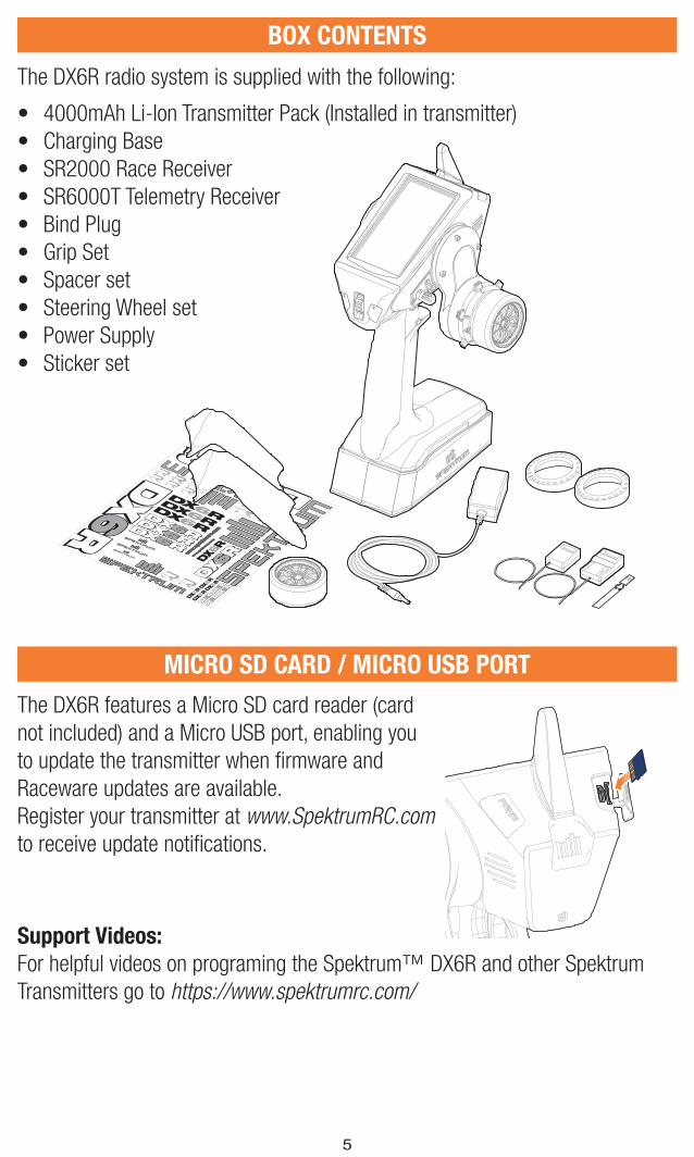
The DX6R radio system is supplied with the following:
• 4000mAh Li-Ion Transmitter Pack (Installed in transmitter)
• Charging Base
• SR2000 Race Receiver
• SR6000T Telemetry Receiver
• Bind Plug
• Grip Set
• Spacer set
• Steering Wheel set
• Power Supply
• Sticker set
Support Videos:
For helpful videos on programing the Spektrum™ DX6R and other Spektrum
Transmitters go to https://www.spektrumrc.com/
The DX6R features a Micro SD card reader (card
not included) and a Micro USB port, enabling you
to update the transmitter when fi rmware and
Raceware updates are available.
Register your transmitter at www.SpektrumRC.com
to receive update notifi cations.
6
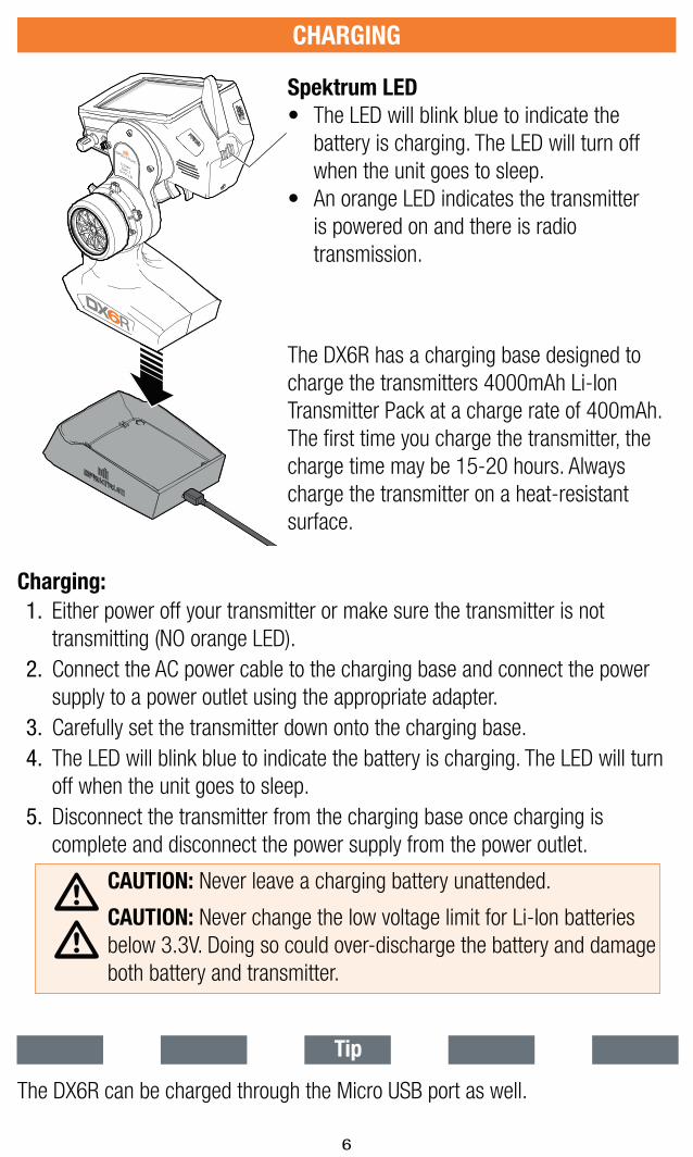
The DX6R has a charging base designed to
charge the transmitters 4000mAh Li-Ion
Transmitter Pack at a charge rate of 400mAh.
The fi rst time you charge the transmitter, the
charge time may be 15-20 hours. Always
charge the transmitter on a heat-resistant
surface.
Charging:
1. Either power off your transmitter or make sure the transmitter is not
transmitting (NO orange LED).
2. Connect the AC power cable to the charging base and connect the power
supply to a power outlet using the appropriate adapter.
3. Carefully set the transmitter down onto the charging base.
4. The LED will blink blue to indicate the battery is charging. The LED will turn
off when the unit goes to sleep.
5. Disconnect the transmitter from the charging base once charging is
complete and disconnect the power supply from the power outlet.
CAUTION: Never leave a charging battery unattended.
CAUTION: Never change the low voltage limit for Li-Ion batteries
below 3.3V. Doing so could over-discharge the battery and damage
both battery and transmitter.
CHARGING
Spektrum LED
• The LED will blink blue to indicate the
battery is charging. The LED will turn off
when the unit goes to sleep.
• An orange LED indicates the transmitter
is powered on and there is radio
transmission.
Tip
The DX6R can be charged through the Micro USB port as well.
7
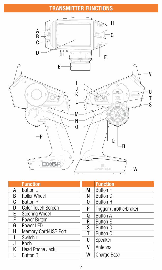
FunctionA Button LB Roller WheelC Button RD Color Touch ScreenE Steering WheelF Power ButtonG Power LEDH Memory Card/USB PortI Switch IJ KnobK Head Phone JackL Button B
FunctionM Button FN Button GO Button H
P Trigger (throttle/brake)
Q Button AR Button ES Button DT Button C
U Speaker
V Antenna
W Charge Base
TRANSMITTER FUNCTIONS
IJKL
MNO
PQ
R
STU
V
ABC
D
E
F
G
H
W
8
ANDROID OPERATING SYSTEM
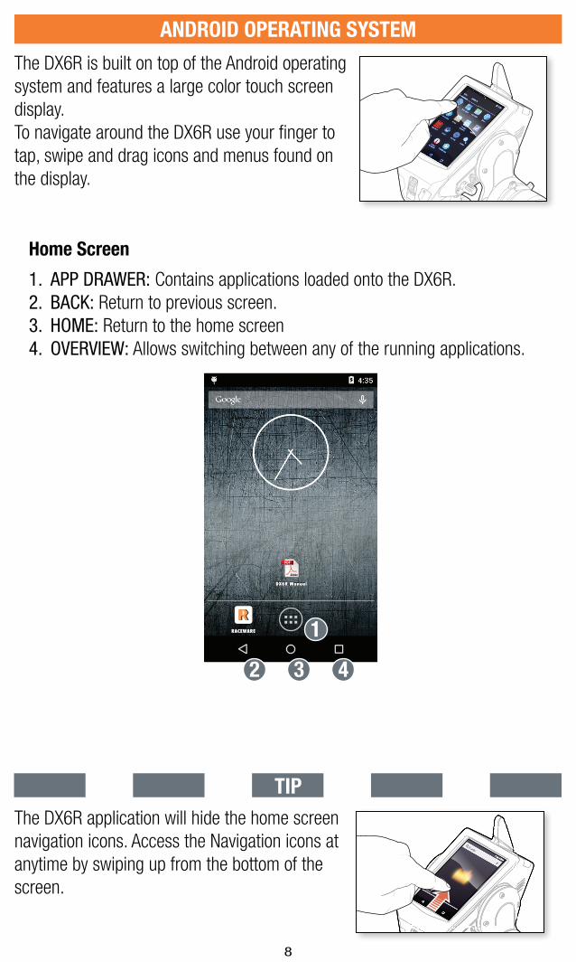
The DX6R is built on top of the Android operating
system and features a large color touch screen
display.
To navigate around the DX6R use your fi nger to
tap, swipe and drag icons and menus found on
the display.
8:168:168:16
AIRWARE
AIRWARE
DX6R Manual
DX6R Manual
8:168:168:168:16
Home Screen
1. APP DRAWER: Contains applications loaded onto the DX6R.
2. BACK: Return to previous screen.
3. HOME: Return to the home screen
4. OVERVIEW: Allows switching between any of the running applications.
RACEWARERACEWARE
DX6R ManualDX6R Manual
2
1
3 4
TIP
The DX6R application will hide the home screen
navigation icons. Access the Navigation icons at
anytime by swiping up from the bottom of the
screen.
9
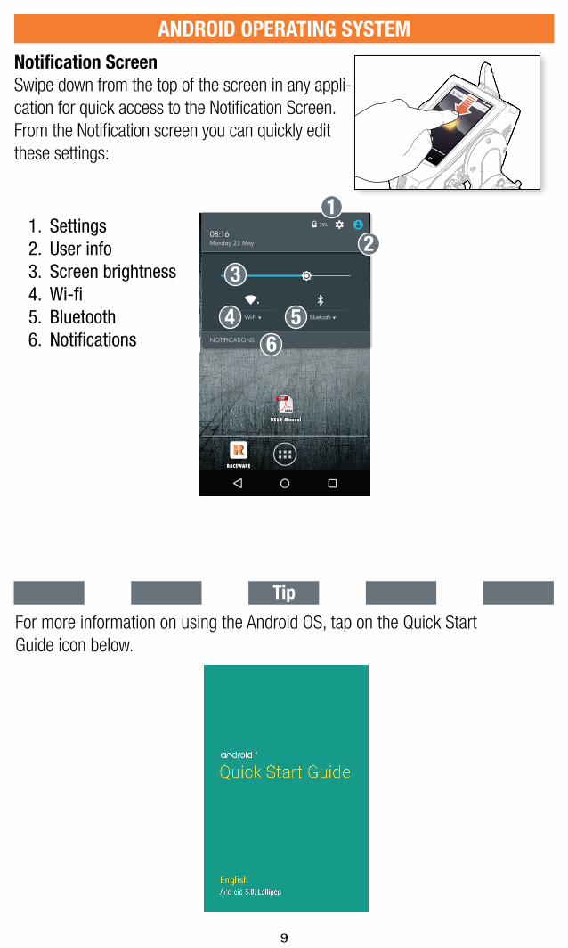
1. Settings 2. User info3. Screen brightness4. Wi-fi 5. Bluetooth6. Notifi cations
Notifi cation Screen
Swipe down from the top of the screen in any appli-
cation for quick access to the Notifi cation Screen.
From the Notifi cation screen you can quickly edit
these settings:
ANDROID OPERATING SYSTEM
75%
08:16Monday 23 May
NOTIFICATIONS
Wi-Fi Bluetooth
RACEWARERACEWARE
DX6R ManualDX6R Manual
2
1
3
4 5
6
8:168:168:16
AIRWARE
AIRWARE
DX6R Manual
DX6R Manual
8:168:168:168:16
For more information on using the Android OS, tap on the Quick Start
Guide icon below.
Tip
10
ANDROID OPERATING SYSTEM
75%
08:16Monday 23 May
NOTIFICATIONS
Wi-Fi Bluetooth
RACEWARERACEWARE
DX6R ManualDX6R Manual
77775555%
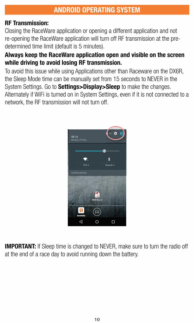
RF Transmission:
Closing the RaceWare application or opening a different application and not
re-opening the RaceWare application will turn off RF transmission at the pre-
determined time limit (default is 5 minutes).
Always keep the RaceWare application open and visible on the screen
while driving to avoid losing RF transmission.
To avoid this issue while using Applications other than Raceware on the DX6R,
the Sleep Mode time can be manually set from 15 seconds to NEVER in the
System Settings. Go to Settings>Display>Sleep to make the changes.
Alternately if WiFi is turned on in System Settings, even if it is not connected to a
network, the RF transmission will not turn off.
IMPORTANT: If Sleep time is changed to NEVER, make sure to turn the radio off
at the end of a race day to avoid running down the battery.
11
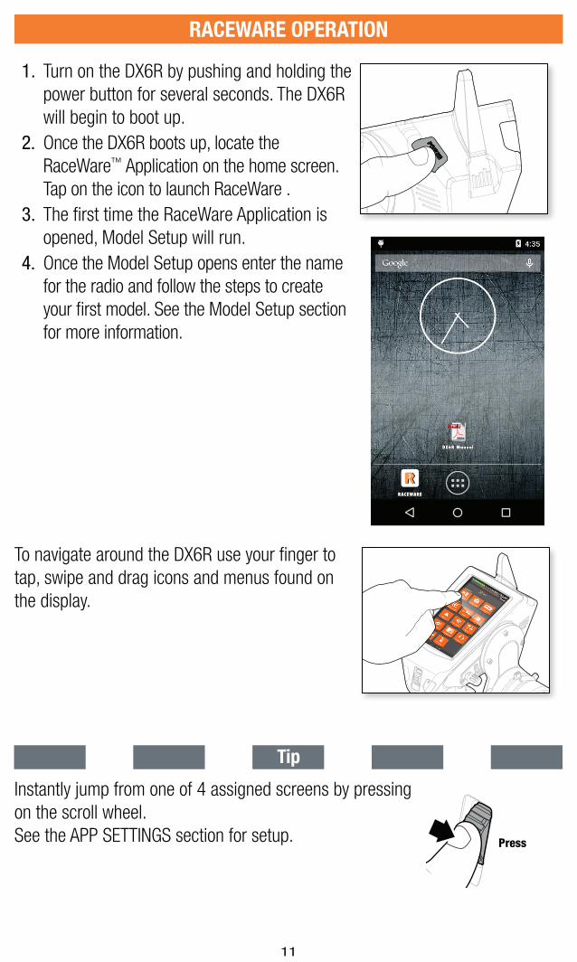
1. Turn on the DX6R by pushing and holding the
power button for several seconds. The DX6R
will begin to boot up.
2. Once the DX6R boots up, locate the
RaceWare™ Application on the home screen.
Tap on the icon to launch RaceWare .
3. The fi rst time the RaceWare Application is
opened, Model Setup will run.
4. Once the Model Setup opens enter the name
for the radio and follow the steps to create
your fi rst model. See the Model Setup section
for more information.
RACEWARE OPERATION
RACEWARERACEWARE
DX6R ManualDX6R Manual
To navigate around the DX6R use your fi nger to
tap, swipe and drag icons and menus found on
the display.
Instantly jump from one of 4 assigned screens by pressing
on the scroll wheel.
See the APP SETTINGS section for setup. Press
Tip
12
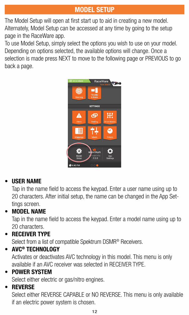
MODEL SETUP
The Model Setup will open at fi rst start up to aid in creating a new model.
Alternately, Model Setup can be accessed at any time by going to the setup
page in the RaceWare app.
To use Model Setup, simply select the options you wish to use on your model.
Depending on options selected, the available options will change. Once a
selection is made press NEXT to move to the following page or PREVIOUS to go
back a page.
• USER NAME
Tap in the name fi eld to access the keypad. Enter a user name using up to
20 characters. After initial setup, the name can be changed in the App Set-
tings screen.
• MODEL NAME
Tap in the name fi eld to access the keypad. Enter a model name using up to
20 characters.
• RECEIVER TYPE
Select from a list of compatible Spektrum DSMR® Receivers.
• AVC® TECHNOLOGY
Activates or deactivates AVC technology in this model. This menu is only
available if an AVC receiver was selected in RECEIVER TYPE.
• POWER SYSTEM
Select either electric or gas/nitro engines.
• REVERSE
Select either REVERSE CAPABLE or NO REVERSE. This menu is only available
if an electric power system is chosen.
13
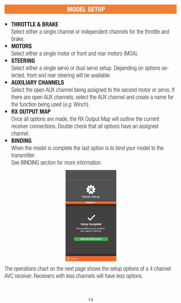
• THROTTLE & BRAKE
Select either a single channel or independent channels for the throttle and
brake.
• MOTORS
Select either a single motor or front and rear motors (MOA).
• STEERING
Select either a single servo or dual servo setup. Depending on options se-
lected, front and rear steering will be available.
• AUXILIARY CHANNELS
Select the open AUX channel being assigned to the second motor or servo. If
there are open AUX channels, select the AUX channel and create a name for
the function being used (e.g. Winch).
• RX OUTPUT MAP
Once all options are made, the RX Output Map will outline the current
receiver connections. Double check that all options have an assigned
channel.
• BINDING
When the model is complete the last option is to bind your model to the
transmitter.
See BINDING section for more information.
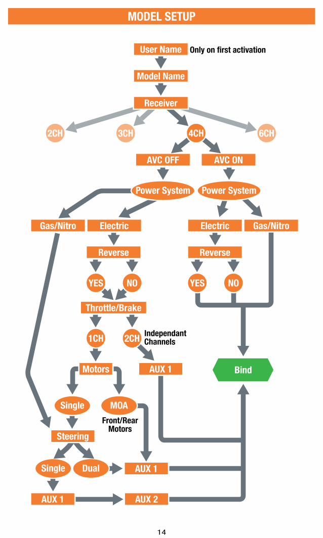
The operations chart on the next page shows the setup options of a 4 channel
AVC receiver. Receivers with less channels will have less options.
MODEL SETUP MODEL SETUP
14
MODEL SETUP
Gas/Nitro Electric
Bind
User Name
Model Name
AVC OFF
Electric
Reverse
Gas/Nitro
AVC ON
2CH 3CH 6CH
Receiver
4CH
Single MOA
Power System Power System
YES NO
Reverse
Motors
Throttle/Brake
YES NO
1CH 2CH
Single Dual
IndependantChannels
Front/RearMotors
Only on first activation
Steering
AUX 1 AUX 2
AUX 1
AUX 1

15
DX6R MAIN SCREENS
The RaceWare application features 3 - 4 main screens depending on the
receiver being used. Simply swipe left or right to move to a different screen.
• Dashboard- The Dashboard is the Home screen for the DX6R. Timers, trims
and rates are all visible at a glance. The Dashboard is the fi rst of 4 main
screens available to the DX6R user.
• TELEMETRY- Telemetry can be found by swiping right from the Dashboard
screen. Telemetry displays all telemetry information including signal strength,
Temperature, RPM and Rx Voltage.
IMPORTANT: TELEMETRY is only available if you are using a telemetry
capable receiver.
• MONITOR- Monitor can be found by swiping right from the Dashboard
or Telemetry screens if available. The Monitor displays the position of the
Steering Wheel, Throttle/Brake, Trims and the position of any AUX channels.
• SETUP- Setup can be found by swiping right from the Monitor screen. Setup
is where the majority of model setup takes place. The Setup screen also has
short cuts for MODEL SETUP and APP SETTINGS.
Dashboard TELEMETRY MONITOR SETUP
• Take note of the circles at the bottom of the screen. The solid circle
represents the current screen location.
• Some screens display more information than can fi t in the window. Use your
fi nger to drag the screen up or down to view all the content.
Tip
16
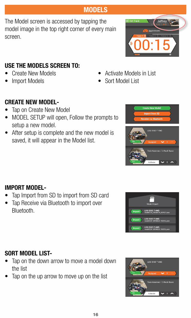
MODELS
CREATE NEW MODEL-
• Tap on Create New Model
• MODEL SETUP will open, Follow the prompts to
setup a new model.
• After setup is complete and the new model is
saved, it will appear in the Model list.
SORT MODEL LIST-
• Tap on the down arrow to move a model down
the list
• Tap on the up arrow to move up on the list
IMPORT MODEL-
• Tap Import from SD to import from SD card
• Tap Receive via Bluetooth to import over
Bluetooth.
The Model screen is accessed by tapping the
model image in the top right corner of every main
screen.
USE THE MODELS SCREEN TO:
• Create New Models
• Import Models
• Activate Models in List
• Sort Model List

17
From inside the MODELS screen, Tap on EDIT
button within the model image to access MODEL
PROPERTIES.
MODEL PROPERTIES
USE THE MODEL PROPERTIES TO:
• Change Model Name
• Change Theme Color
• Change Model Image
• Export Models
• Duplicate Models
• Delete Models
MODEL NAME-
• Tap in the model name box
• Enter up to 20 characters
THEME COLOR-
Tap the COLOR box to select a different theme color
MODEL IMAGE-
• Tap the PHOTO box to change the image
• Use the PHOTO PICKER to select an image from
an SD card
EXPORT MODEL-
• Tap EXPORT to SD to export current model to
SD card
• Tap TRANSFER VIA BLUETOOTH to export a
model directly to another transmitter.
DUPLICATE/DELETE MODEL-
• Tap DUPLICATE THIS MODEL to make a copy of
the current model.
• Tap DELETE MODEL to delete current model.
RESET MODEL-
Tap RESET MODEL to return to defaults.

18
The Setup Screen allows for quick and easy editing
of all model settings.
The Setup Screen is divided into 2 section.
Channels-
Settings-
The bottom of the screen also has quick links
to MODEL SETUP and APP SETTINGS as well as
displaying the version number of the App.
SETUP SCREEN
STEERING
STEERING CURVE
Steering response is adjustable using an EXPO or Custom steering curves.
The STEERING screen allows for programming of all steering functions.
AVAILABLE FUNCTIONS:
• Steering Curve
• Steering Trim
• Steering Speed
• Steering Rate
• Channel Properties
• AWS Mode
• Travel
• Subtrim
• Reverse
Standard- Linear steering output (default)
Exponential- Positive (+) EXPO values decrease
steering sensitivity around neutral.
• Steering • Throttle &Brake/
Reverse
• Aux
• Alerts • Binding • Drive Modes
• Mapping • Timers • AVC
• Telemetry • Mixes

19
On-the-Fly Button-
Select a switch for instant adjustment of the expo
curve while driving.
Custom-
Up to 7 selected points can be adjusted to custom
tailor steering response throughout the range.
• Tap on the line to add points.
• Tap on a point to adjust its position using the
sliders below.
• Delete a point by tapping on it, then select Delete
point (red box above graph)
Look for the ON-THE-FLY BUTTON in most menus.
Allows for on the fl y adjustments of menu items.
Tip
STEERING TRIM-
Steering trim adjusts the steering neutral position.
Steering Trim is defaulted to Switch B but can be
assigned to any trimmer/switch.
• Common-
• Drive Mode-
STEERING SPEED-
Reduces servo output transit time (slows down the
servo). Used on steering to prevent overly sensitive
steering response.
STEERING
20
STEERING
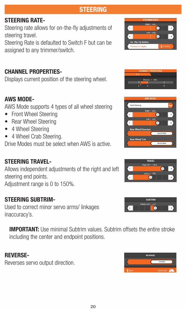
STEERING RATE-
Steering rate allows for on-the-fl y adjustments of
steering travel.
Steering Rate is defaulted to Switch F but can be
assigned to any trimmer/switch.
CHANNEL PROPERTIES-
Displays current position of the steering wheel.
AWS MODE-
AWS Mode supports 4 types of all wheel steering
• Front Wheel Steering
• Rear Wheel Steering
• 4 Wheel Steering
• 4 Wheel Crab Steering.
Drive Modes must be select when AWS is active.
STEERING TRAVEL-
Allows independent adjustments of the right and left
steering end points.
Adjustment range is 0 to 150%.
REVERSE-
Reverses servo output direction.
STEERING SUBTRIM-
Used to correct minor servo arms/ linkages
inaccuracy’s.
IMPORTANT: Use minimal Subtrim values. Subtrim offsets the entire stroke
including the center and endpoint positions.

21
THROTTLE & BRAKE/REVERSE
THROTTLE CURVE-
Throttle response is adjustable using an EXPO or Custom throttle curves.
The Throttle & Reverse screen allows for programming of all throttle and brake
functions.
AVAILABLE FUNCTIONS:
• Throttle Curve
• Throttle Trim
• Throttle Rate
• Reverse Rate
• Traction Control
• ABS
• Servo Speed
• Channel Properties
• Travel
• Subtrim
• Reverse
Standard- Linear throttle output (default)
Exponential- Positive (+) EXPO values decrease
throttle sensitivity around neutral.
Custom- Up to 7 selected points can be adjusted
to custom tailor throttle response throughout the
range.
• Tap on the line to add points.
• Tap on a point to adjust its position using the
sliders below.
• Delete a point by tapping on it, then select
Delete point (red box above graph)
On-the-Fly Button- Select a switch for instant
adjustment of the expo curve while driving.

22
BRAKE CURVE-
Brake response is adjustable using an EXPO or Custom Brake curves.
Standard- Linear output (default)
Exponential- Positive (+) EXPO values decrease
brake sensitivity around neutral.
Custom- Up to 7 selected points can be adjusted
to custom tailor brake response throughout the
range.
• Tap on the line to add points.
• Tap on a point to adjust its position using the
sliders below.
• Delete a point by tapping on it, then select
Delete point (red box above graph)
On-the-Fly Button- Select a switch for instant
adjustment of the expo curve while driving.
THROTTLE & BRAKE/REVERSE
THROTTLE TRIM-
Throttle trim adjusts the steering neutral position
and is used to adjust static brakes.
Throttle Trim is defaulted to Switch A but can be
assigned to any trimmer/switch.
• Common-
• Drive Mode-
THROTTLE RATE-
Throttle rate is a full throttle limiter that limits the full
throttle position.
Throttle Rate can be assigned to any trimmer/witch.
23
THROTTLE & BRAKE/REVERSE
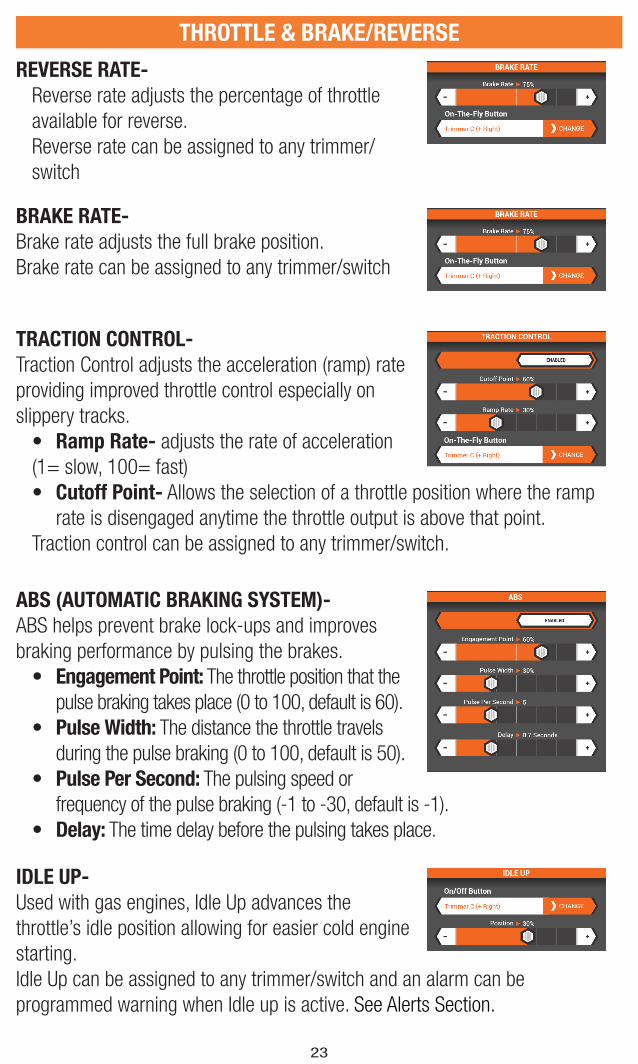
REVERSE RATE-
Reverse rate adjusts the percentage of throttle
available for reverse.
Reverse rate can be assigned to any trimmer/
switch
BRAKE RATE-
Brake rate adjusts the full brake position.
Brake rate can be assigned to any trimmer/switch
TRACTION CONTROL-
Traction Control adjusts the acceleration (ramp) rate
providing improved throttle control especially on
slippery tracks.
• Ramp Rate- adjusts the rate of acceleration
(1= slow, 100= fast)
• Cutoff Point- Allows the selection of a throttle position where the ramp
rate is disengaged anytime the throttle output is above that point.
Traction control can be assigned to any trimmer/switch.
ABS (AUTOMATIC BRAKING SYSTEM)-
ABS helps prevent brake lock-ups and improves
braking performance by pulsing the brakes.
• Engagement Point: The throttle position that the
pulse braking takes place (0 to 100, default is 60).
• Pulse Width: The distance the throttle travels
during the pulse braking (0 to 100, default is 50).
• Pulse Per Second: The pulsing speed or
frequency of the pulse braking (-1 to -30, default is -1).
• Delay: The time delay before the pulsing takes place.
IDLE UP-
Used with gas engines, Idle Up advances the
throttle’s idle position allowing for easier cold engine
starting.
Idle Up can be assigned to any trimmer/switch and an alarm can be
programmed warning when Idle up is active. See Alerts Section.

24
THROTTLE & BRAKE/REVERSE
AWD MODE- (MOA)-
Motor-On-Axle (MOA) programming allows on the
fl y power distribution from the front to rear wheels.
Adjustable ranges from 100% rear 0% front to 0%
rear 100% front. When activated the default setting is 50%/50% and this setting
can be adjusted and stored using drive modes or assigned to a trimmer/ Switch.
SERVO SPEED-
Reduces servo output transit time (slows down the
servo).
Servo Speed can be assigned to any trimmer/switch
CHANNEL PROPERTIES-
Displays current position of the steering wheel.
TRAVEL-
Allows independent precise adjustments of the
brake end points.
REVERSE-
Reverses servo output direction.
THROTTLE SUBTRIM-
Used to correct minor servo arms/ linkages
inaccuracy’s.
IMPORTANT: Use minimal Subtrim values. Subtrim offsets the entire stroke
including the center and endpoint positions.
25
AUXILIARY (AUX) CHANNEL SETUP
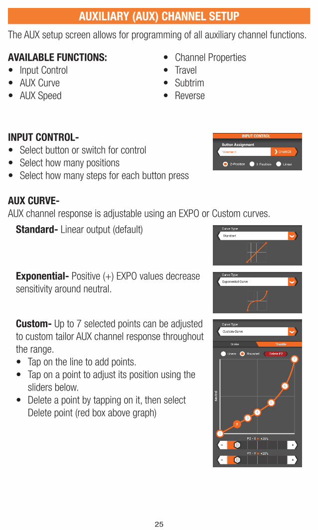
AUX CURVE-
AUX channel response is adjustable using an EXPO or Custom curves.
INPUT CONTROL-
• Select button or switch for control
• Select how many positions
• Select how many steps for each button press
The AUX setup screen allows for programming of all auxiliary channel functions.
AVAILABLE FUNCTIONS:
• Input Control
• AUX Curve
• AUX Speed
• Channel Properties
• Travel
• Subtrim
• Reverse
Standard- Linear output (default)
Exponential- Positive (+) EXPO values decrease
sensitivity around neutral.
Custom- Up to 7 selected points can be adjusted
to custom tailor AUX channel response throughout
the range.
• Tap on the line to add points.
• Tap on a point to adjust its position using the
sliders below.
• Delete a point by tapping on it, then select
Delete point (red box above graph)
26
AUXILIARY (AUX) CHANNEL SETUP
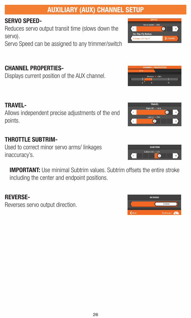
SERVO SPEED-
Reduces servo output transit time (slows down the
servo).
Servo Speed can be assigned to any trimmer/switch
CHANNEL PROPERTIES-
Displays current position of the AUX channel.
TRAVEL-
Allows independent precise adjustments of the end
points.
REVERSE-
Reverses servo output direction.
THROTTLE SUBTRIM-
Used to correct minor servo arms/ linkages
inaccuracy’s.
IMPORTANT: Use minimal Subtrim values. Subtrim offsets the entire stroke
including the center and endpoint positions.
27
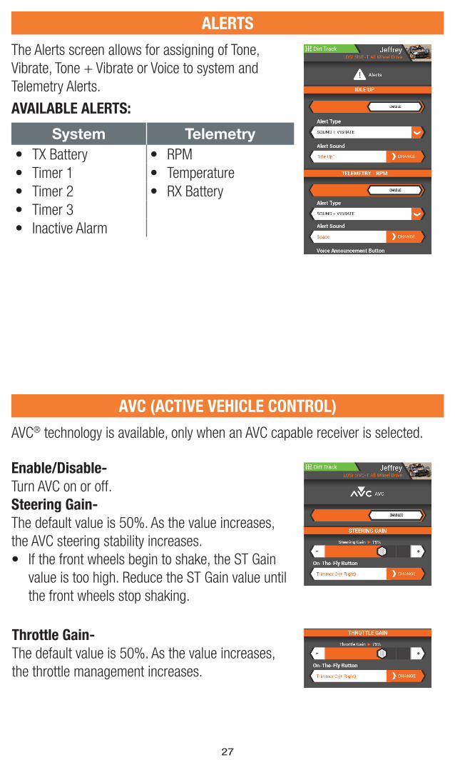
The Alerts screen allows for assigning of Tone,
Vibrate, Tone + Vibrate or Voice to system and
Telemetry Alerts.
ALERTS
AVAILABLE ALERTS:
System Telemetry• TX Battery • RPM
• Timer 1 • Temperature
• Timer 2 • RX Battery
• Timer 3
• Inactive Alarm
AVC® technology is available, only when an AVC capable receiver is selected.
Enable/Disable-
Turn AVC on or off.
Steering Gain-
The default value is 50%. As the value increases,
the AVC steering stability increases.
• If the front wheels begin to shake, the ST Gain
value is too high. Reduce the ST Gain value until
the front wheels stop shaking.
Throttle Gain-
The default value is 50%. As the value increases,
the throttle management increases.
AVC (ACTIVE VEHICLE CONTROL)

28
BINDING
Binding is the Process of teaching the receiver the specifi c transmitter’s code
called GUID (Globally Unique Identifi er) and storing failsafe values. When a
receiver is bound to a transmitter/model memory, the receiver will only respond
to that specifi c transmitter/model memory.
1. Tap the Desired Frame Rate drop down to select
from 5.5ms, 11ms and 22ms.
• If 5.5ms frame rate is selected in the
transmitter, only two channels, Steering and
Throttle, are operational. The Aux channels
can be used to power a personal transponder
or lights.
• If a frame rate other than 5.5ms is selected,
the Aux channels will operate as extra servo
channels.
2. With the receiver in bind mode Tap the Begin
Binding button.
IMPORTANT: Re-bind any time you change the frame rate in the transmitter.
AVC (ACTIVE VEHICLE CONTROL)
Priority-
The default value is 0%, meaning AVC technology
is active throughout the steering range. As you
turn the steering wheel away from center (neutral),
the transmitter controls have priority over the AVC
system. Increasing the Priority value decreases how
active AVC is as the steering wheel is turned left and
right. For example, if you increase Priority to 80%,
you reduce the AVC steering control by 80% at full
left or full right steering. Increasing the Steering
Priority enables you to make tighter turns.

29
DRIVE MODES
The current drive mode is always displayed in the
top left corner of the 4 main screens.
Every model can have several drive modes
programmed to a switch or button for on-the-fl y
adjustments.
Once a drive mode is selected, Changes to model
setup, trim and timers will only effect that drive mode.
• Tap the ON-the-Fly Button drop down to select a
button or switch to enable instant mode changes.
• Tap on the Drive Mode button to change the drive
mode name
• Tap on Flag Color to change the color of the Drive
mode banner.
• Tap on Delete to delete drive modes (there must
be at least 1 drive mode).
• If more than 1 drive mode, tap on the arrow
buttons to order the list.
The Mapping screen displays an overview of all
transmitter and receiver functions as they are
currently setup for the active model. Use the
mapping screen to help correctly connect servo and
auxiliary equipment into the correct receiver port.
MAPPING

30
TELEMETRY
TIMERS
The Telemetry SetUp Screen allows for editing values as well as how the
information is displayed on the Telemetry Screen.
• Tap DISPLAY to Hide the telemetry information
on the Telemetry screen. If information is already
hidden, tap Hide to show.
• Change Minimum values displayed (per sensor)
• Change Maximum values displayed (per sensor)
• Change Warning Threshold (per sensor)
• Choose motor sensor type and Pole Count to
accurately display motor RPM’s
• Select drive ratios and tire diameter to accurately
display model speeds.
AVAILABLE FUNCTIONS:
• Temperature
• Receiver Battery
• Speed/RPM
• Sensor Type
• Roll-Out
AVAILABLE TIMERS:
• Total Time
• Model Time
• Up Timer
• Down Timer
• Rolling Lap Timer
The DX6R offers 5 timers, all viewable from the
Dashboard. Pause and Reset the timers directly on
the dashboard or confi gure a Timer switch or button.
To confi gure the timers and to clear Model Time and
Total Drive Time go to the Timers screen in SetUp.
31
TIMERS
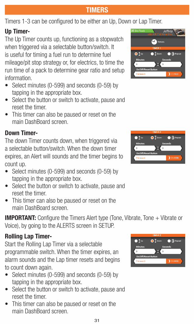
Timers 1-3 can be confi gured to be either an Up, Down or Lap Timer.
Up Timer-
The Up Timer counts up, functioning as a stopwatch
when triggered via a selectable button/switch. It
is useful for timing a fuel run to determine fuel
mileage/pit stop strategy or, for electrics, to time the
run time of a pack to determine gear ratio and setup
information. • Select minutes (0-599) and seconds (0-59) by
tapping in the appropriate box.• Select the button or switch to activate, pause and
reset the timer.• This timer can also be paused or reset on the
main DashBoard screen.
Down Timer-
The down Timer counts down, when triggered via
a selectable button/switch. When the down timer
expires, an Alert will sounds and the timer begins to
count up.• Select minutes (0-599) and seconds (0-59) by
tapping in the appropriate box.• Select the button or switch to activate, pause and
reset the timer.• This timer can also be paused or reset on the
main DashBoard screen.
Rolling Lap Timer-
Start the Rolling Lap Timer via a selectable
programmable switch. When the timer expires, an
alarm sounds and the Lap timer resets and begins
to count down again.• Select minutes (0-599) and seconds (0-59) by
tapping in the appropriate box.• Select the button or switch to activate, pause and
reset the timer.• This timer can also be paused or reset on the
main DashBoard screen.
IMPORTANT: Confi gure the Timers Alert type (Tone, Vibrate, Tone + Vibrate or
Voice), by going to the ALERTS screen in SETUP.
32
SYSTEM SETTINGS
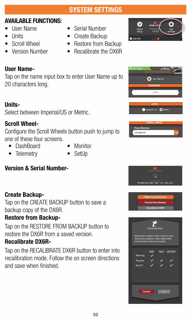
AVAILABLE FUNCTIONS:
• User Name
• Units
• Scroll Wheel
• Version Number
• Serial Number
• Create Backup
• Restore from Backup
• Recalibrate the DX6R
User Name-
Tap on the name input box to enter User Name up to
20 characters long.
Units-
Select between Imperial/US or Metric.
Version & Serial Number-
Scroll Wheel-
Confi gure the Scroll Wheels button push to jump to
one of these four screens.
Create Backup-
Tap on the CREATE BACKUP button to save a
backup copy of the DX6R.
Restore from Backup-
Tap on the RESTORE FROM BACKUP button to
restore the DX6R from a saved version.
Recalibrate DX6R-
Tap on the RECALIBRATE DX6R button to enter into
recalibration mode. Follow the on screen directions
and save when fi nished.
• DashBoard
• Telemetry
• Monitor
• SetUp
33
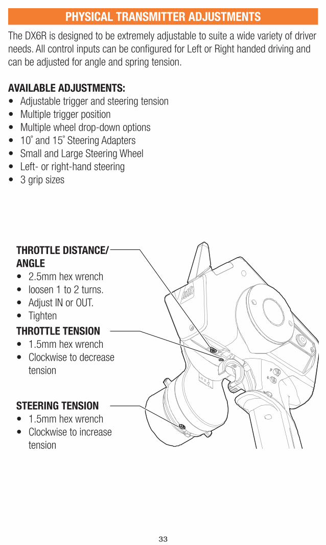
PHYSICAL TRANSMITTER ADJUSTMENTS
The DX6R is designed to be extremely adjustable to suite a wide variety of driver
needs. All control inputs can be confi gured for Left or Right handed driving and
can be adjusted for angle and spring tension.
AVAILABLE ADJUSTMENTS:
• Adjustable trigger and steering tension
• Multiple trigger position
• Multiple wheel drop-down options
• 10˚ and 15˚ Steering Adapters
• Small and Large Steering Wheel
• Left- or right-hand steering
• 3 grip sizes
THROTTLE DISTANCE/
ANGLE
• 2.5mm hex wrench
• loosen 1 to 2 turns.
• Adjust IN or OUT.
• Tighten
THROTTLE TENSION
• 1.5mm hex wrench
• Clockwise to decrease
tension
STEERING TENSION
• 1.5mm hex wrench
• Clockwise to increase
tension

34
PHYSICAL TRANSMITTER ADJUSTMENTS
DROPDOWN STEERING WHEEL OPTIONS
The DX6R comes with the dropdown wheel installed. The dropdown can be
rotated for a perfect feel or removed for a standard wheel layout. All the parts
necessary to convert to the standard wheel are included.
ROTATE:
• Turn off the DX6R
• Using a 2mm hex wrench, remove 3
screws.
• Rotate the drop down to the desired
angle.
• Align with the screw holes and re-
install the 3 screws being careful not
to pinch any wires.
STANDARD WHEEL CONVERSION:
• Using a 2mm hex wrench, remove the 3 screws from the drop down and
remove the drop down from the transmitter. Carefully disconnect the 2 wiring
harness from inside the transmitter.
• Using a 1.5mm hex wrench, remove the steering wheel.
• Using a 2mm hex wrench, remove 2 screws from the steering mechanism.
Remove the steering mechanism from the drop down being careful to pull the
wiring harness through the opening.
• Keep the drop down in a safe place for future use.
• Connect the 2 wiring harnesses to the board inside the DX6R. Note that one
connector has 6 pins and
the other has 7.
• Re-install the steering
mechanism directly onto
the transmitter using the 2
screws
• Re-install the steering
wheel.
Wiring not shown
There are two wheel CAM’s included with the DX6R. They attach to the steering
mechanism and physically limit the wheel travel. Use the 32º CAM with the large
wheel and the 36º CAM with the Small steering wheel.
Tip
CAM
35
PHYSICAL TRANSMITTER ADJUSTMENTS
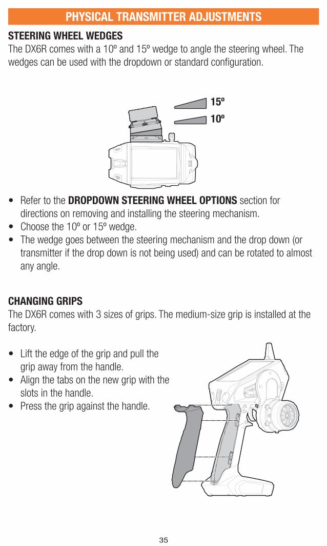
STEERING WHEEL WEDGES
The DX6R comes with a 10º and 15º wedge to angle the steering wheel. The
wedges can be used with the dropdown or standard confi guration.
CHANGING GRIPS
The DX6R comes with 3 sizes of grips. The medium-size grip is installed at the
factory.
• Lift the edge of the grip and pull the
grip away from the handle.
• Align the tabs on the new grip with the
slots in the handle.
• Press the grip against the handle.
• Refer to the DROPDOWN STEERING WHEEL OPTIONS section for
directions on removing and installing the steering mechanism.
• Choose the 10º or 15º wedge.
• The wedge goes between the steering mechanism and the drop down (or
transmitter if the drop down is not being used) and can be rotated to almost
any angle.
15º
10º

36
PHYSICAL TRANSMITTER ADJUSTMENTS
CHANGING FROM RIGHT HANDED TO LEFT HANDED
The DX6R can be confi gured for either right or left handed drivers.
STEERING MECHANISM:
• Turn off the DX6R
• Using a 2mm hex wrench, remove 3
screws.
• Carefully remove the 2 wire
connectors from the board inside the
transmitter.
• Set aside
BACK COVER:
• Using a 2mm hex wrench, remove 2
screws.
• Remove the back cover and re-
install on the opposite side of the
transmitter.
STEERING MECHANISM:
• Connect the 2 wire connectors to the
board inside the DX6R. Note that one
connector has 6 pins and the other
has 7.
• Align with screw holes and re-install
the 3 screws being careful not to
pinch any wires.
Wiring not shown
37
PHYSICAL TRANSMITTER ADJUSTMENTS
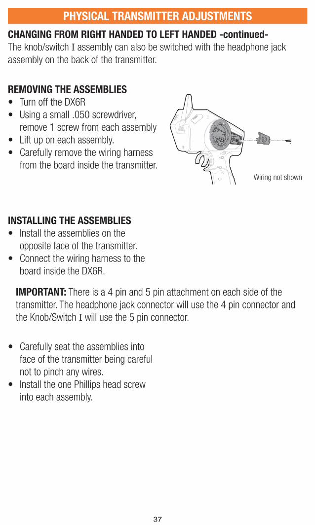
CHANGING FROM RIGHT HANDED TO LEFT HANDED -continued-
The knob/switch I assembly can also be switched with the headphone jack
assembly on the back of the transmitter.
REMOVING THE ASSEMBLIES
• Turn off the DX6R
• Using a small .050 screwdriver,
remove 1 screw from each assembly
• Lift up on each assembly.
• Carefully remove the wiring harness
from the board inside the transmitter.
INSTALLING THE ASSEMBLIES
• Install the assemblies on the
opposite face of the transmitter.
• Connect the wiring harness to the
board inside the DX6R.
• Carefully seat the assemblies into
face of the transmitter being careful
not to pinch any wires.
• Install the one Phillips head screw
into each assembly.
Wiring not shown
IMPORTANT: There is a 4 pin and 5 pin attachment on each side of the
transmitter. The headphone jack connector will use the 4 pin connector and
the Knob/Switch I will use the 5 pin connector.

38
SR2000 Micro Race receiver
The Spektrum™ SR2000 DSMR® Micro Race receiver is compatible with all Spektrum DSMR transmitters and is also backwards compatible with DSM2® transmitters. The SR2000 receiver is NOT compatible with DSM® transmitters.
Specifi cations
Type: DSMR
Dimensions (LxWxH): 25.5 x 17.6 x 13.6mm
Channels: 2
Weight: 5.5 gBand: 2.4GHz
Voltage Range: 3.5–9.6V
SR6000T Telemetry ReceiverThe Spektrum SR6000T Telemetry Re-ceiver is compatible with all Spektrum DSMR surface transmitters. Telemetry functions require a Spektrum transmi-tter capable of telemetry.
Specifi cations
Type: DSMR with internal telemetry
Dimensions (LxWxH): 37.5 x 27.7 x 15.7mm
Antenna Length: 210mm
Channels: 6Weight: 9.2 gBand: 2.4GHz
Voltage Range: 3.5–9.6V
For full receiver manuals go to https://www.spektrumrc.com/
INCLUDED SR2000/SR6000T RECEIVERS
39
What this Warranty Covers - Horizon Hobby,
LLC, (Horizon) warrants to the original purchaser
that the product purchased (the “Product”) will be
free from defects in materials and workmanship for
a period of 1 year from the date of purchase.
What is Not CoveredThis warranty is not transferable and does not cover
(i) cosmetic damage, (ii) damage due to acts of God,
accident, misuse, abuse, negligence, commercial
use, or due to improper use, installation, operation
or maintenance, (iii) modifi cation of or to any part of
the Product, (iv) attempted service by anyone other
than a Horizon Hobby authorized service center, (v)
Product not purchased from an authorized Horizon
dealer, (vi) Product not compliant with applicable
technical regulations, or (vii) use that violates any
applicable laws, rules, or regulations.
OTHER THAN THE EXPRESS WARRANTY ABOVE,
HORIZON MAKES NO OTHER WARRANTY OR
REPRESENTATION, AND HEREBY DISCLAIMS ANY
AND ALL IMPLIED WARRANTIES, INCLUDING,
WITHOUT LIMITATION, THE IMPLIED WARRANTIES
OF NON-INFRINGEMENT, MERCHANTABILITY
AND FITNESS FOR A PARTICULAR PURPOSE. THE
PURCHASER ACKNOWLEDGES THAT THEY ALONE
HAVE DETERMINED THAT THE PRODUCT WILL
SUITABLY MEET THE REQUIREMENTS OF THE
PURCHASER’S INTENDED USE.
Purchaser’s RemedyHorizon’s sole obligation and purchaser’s sole and
exclusive remedy shall be that Horizon will, at its
option, either (i) service, or (ii) replace, any Product
determined by Horizon to be defective. Horizon
reserves the right to inspect any and all Product(s)
involved in a warranty claim. Service or replacement
decisions are at the sole discretion of Horizon. Proof
of purchase is required for all warranty claims.
SERVICE OR REPLACEMENT AS PROVIDED UNDER
THIS WARRANTY IS THE PURCHASER’S SOLE AND
EXCLUSIVE REMEDY.
Limitation of LiabilityHORIZON SHALL NOT BE LIABLE FOR SPECIAL,
INDIRECT, INCIDENTAL OR CONSEQUENTIAL
DAMAGES, LOSS OF PROFITS OR PRODUCTION OR
COMMERCIAL LOSS IN ANY WAY, REGARDLESS OF
WHETHER SUCH CLAIM IS BASED IN CONTRACT,
WARRANTY, TORT, NEGLIGENCE, STRICT LIABILITY
OR ANY OTHER THEORY OF LIABILITY, EVEN IF
HORIZON HAS BEEN ADVISED OF THE POSSIBILITY
OF SUCH DAMAGES. Further, in no event shall the
liability of Horizon exceed the individual price of the
Product on which liability is asserted. As Horizon
has no control over use, setup, fi nal assembly,
modifi cation or misuse, no liability shall be assumed
nor accepted for any resulting damage or injury. By
the act of use, setup or assembly, the user accepts
all resulting liability. If you as the purchaser or user
are not prepared to accept the liability associated
with the use of the Product, purchaser is advised to
return the Product immediately in new and unused
condition to the place of purchase.
LawThese terms are governed by Illinois law (without
regard to confl ict of law principals). This warranty
gives you specifi c legal rights, and you may also
have other rights which vary from state to state.
Horizon reserves the right to change or modify this
warranty at any time without notice.
WARRANTY SERVICESQuestions, Assistance, and Services
Your local hobby store and/or place of purchase
cannot provide warranty support or service. Once
assembly, setup or use of the Product has been
started, you must contact your local distributor or
Horizon directly. This will enable Horizon to better
answer your questions and service you in the event
that you may need any assistance. For questions
or assistance, please visit our website at www.
horizonhobby.com, submit a Product Support
Inquiry, or call the toll free telephone number
referenced in the Warranty and Service Contact
Information section to speak with a Product Support
representative.
Inspection or ServicesIf this Product needs to be inspected or serviced
and is compliant in the country you live and use the
Product in, please use the Horizon Online Service
Request submission process found on our website
or call Horizon to obtain a Return Merchandise
Authorization (RMA) number. Pack the Product
securely using a shipping carton. Please note
that original boxes may be included, but are not
designed to withstand the rigors of shipping without
additional protection. Ship via a carrier that provides
tracking and insurance for lost or damaged parcels,
as Horizon is not responsible for merchandise
until it arrives and is accepted at our facility. An
Online Service Request is available at http://www.
horizonhobby.com/content/service-center_render-
service-center. If you do not have internet access,
please contact Horizon Product Support to obtain a
RMA number along with instructions for submitting
your product for service. When calling Horizon,
you will be asked to provide your complete name,
street address, email address and phone number
where you can be reached during business hours.
1-YEAR LIMITED WARRANTY
40
5-14-2015
When sending product into Horizon, please include
your RMA number, a list of the included items, and
a brief summary of the problem. A copy of your
original sales receipt must be included for warranty
consideration. Be sure your name, address, and
RMA number are clearly written on the outside of
the shipping carton.
NOTICE: Do not ship LiPo batteries to Horizon. If you have any issue with a LiPo battery, please contact the appropriate Horizon Product Support offi ce.Warranty Requirements For Warranty consideration, you must include your
original sales receipt verifying the proof-of-purchase
date. Provided warranty conditions have been met,
your Product will be serviced or replaced free of
charge. Service or replacement decisions are at the
sole discretion of Horizon.
Non-Warranty ServiceShould your service not be covered by warranty,
service will be completed and payment will be
required without notifi cation or estimate of the
expense unless the expense exceeds 50% of the
retail purchase cost. By submitting the item for
service you are agreeing to payment of the service
without notifi cation. Service estimates are available
upon request. You must include this request with
your item submitted for service. Non-warranty
service estimates will be billed a minimum of ½
hour of labor. In addition you will be billed for return
freight. Horizon accepts money orders and cashier’s
checks, as well as Visa, MasterCard, American
Express, and Discover cards. By submitting any item
to Horizon for service, you are agreeing to Horizon’s
Terms and Conditions found on our website http://
www.horizonhobby.com/content/service-center_
render-service-center.
ATTENTION: Horizon service is limited to Product compliant in the country of use and ownership. If received, a non-compliant Product will not be serviced. Further, the sender will be responsible for arranging return shipment of the un-serviced Product, through a carrier of the sender’s choice and at the sender’s expense. Horizon will hold non-compliant Product for a period of 60 days from notifi cation, after which it will be discarded.
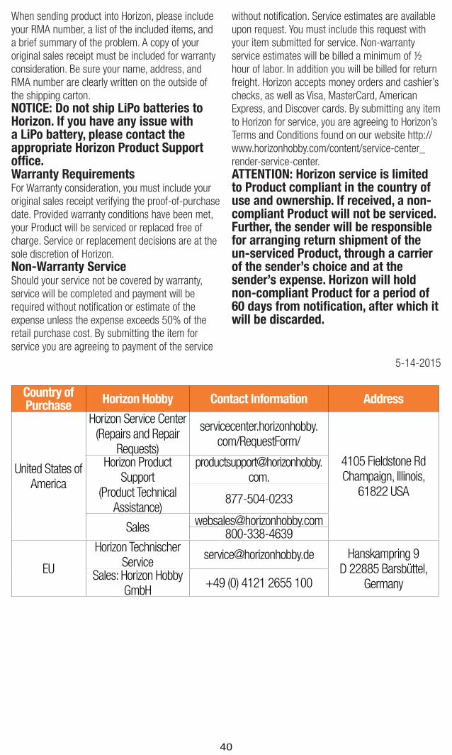
Country of Purchase
Horizon Hobby Contact Information Address
United States of America
Horizon Service Center(Repairs and Repair
Requests)
servicecenter.horizonhobby.com/RequestForm/
4105 Fieldstone Rd Champaign, Illinois,
61822 USA
Horizon Product Support
(Product Technical Assistance)
877-504-0233
800-338-4639
EU
Horizon Technischer Service
[email protected] Hanskampring 9D 22885 Barsbüttel,
GermanySales: Horizon Hobby
GmbH+49 (0) 4121 2655 100

41
FCC INFORMATION
This device complies with part 15 of the FCC rules. Operation is subject to the following two conditions: 1. This device may not cause harmful interference.2. This device must accept any interference received, including interference that
may cause undesired operation.
CAUTION: Changes or modifi cations not expressly approved by the party responsible for compliance could void the user’s authority to
operate the equipment.
This product contains a radio transmitter with wireless technology which has been tested and found to be compliant with the applicable regulations governing a radio transmitter in the 2.400GHz to 2.4835GHz frequency range.
This equipment has been tested and found to comply with the limits for Part 15 of the FCC rules. These limits are designed to provide reasonable protection against harmful interference in a residential installation. This equipment generates uses and can radiate radio frequency energy and, if not installed and used in accordance with the instructions, may cause harmful interference to radio communications.
However, there is no guarantee that interference will not occur in a particular installation. If this equipment does cause harmful interference to radio or television reception, which can be determined by turning the equipment off and on, the user is encouraged to try to correct the interference by one or more of the following measures:
• Reorient or relocate the receiving antenna.
• Increase the separation between the equipment and receiver.
• Connect the equipment to an outlet on a circuit different from that to which the receiver is connected.
This device complies with part 15 of the FCC rules. Operation is subject to the following two conditions: (1) This device may not cause harmful interference, and (2) this device must accept any interference received, including interference that may cause undesired operation.
NOTICE: Modifi cations to this product will void the user’s authority to operate this equipment.

42
Horizon Hobby, LLC hereby declares that this product is in compliance with the essential requirements and other relevant provisions of the RED Directive. A copy of the EU Declaration of Conformity is available online at:
http://www.horizonhobby.com/content/support-render-compliance.
Instructions for Disposal of WEEE by Users in the European UnionThis product must not be disposed of with other waste. Instead, it is the user’s responsibility to dispose of their waste equipment by handing it over to a designated collection point for the recycling of waste electrical and electronic
equipment. The separate collection and recycling of your waste equipment at the time of disposal will help to conserve natural resources and ensure that it is recycled in a manner that protects human health and the environment. For more information about where you can drop off your waste equipment for recycling, please contact your local city offi ce, your household waste disposal service or where you purchased the product.
COMPLIANCE INFORMATION FOR THE EUROPEAN UNION
IC INFORMATION
This device complies with Industry Canada license-exempt RSS standard(s).
Operation is subject to the following two conditions: (1) this device may not
cause interference, and (2) this device must accept any interference, Including
interference that may cause undesired operation of the device.
Antenna Separation Distance
When operating your Spektrum transmitter, please be sure to maintain a separation distance of at least 5 cm between your body (excluding fi ngers, hands, wrists, ankles and feet) and the antenna to meet RF exposure safety requirements as determined by FCC regulations.
The illustrations show the approximate 20 cm RF exposure area and typical hand placement when operating your Spektrum transmitter.
20 cm
53706.1 EU
© 2017 Horizon Hobby, LLC.DSM, DSM2, DSMR and RaceWare are trademarks or registered trademarks of Horizon Hobby, LLC.The Spektrum trademark is used with permission of Bachmann Industries, Inc.Android is a trademark of Google Inc. The Bluetooth® word mark and logos are registered trademarks owned by Bluetooth SIG, Inc. and any use of such marks by Horizon Hobby is under license. The WiFi logo is a registered trademark of WiFi Alliance. The SD Logo is a trademark of SD-3C, LLC.All other trademarks, service marks and logos are property of their respective owners. US 9,320,977. Other patents pending.
3/17