527 - 746 kWm (Gross) @ 1500/1800 rpm 4006-23TAG3A...
12
Perkins Engines Company Limited Peterborough, PE1 5FQ, United Kingdom Tel: +44 (0)1733 583000 Fax: +44 (0)1733 582240 www.perkins.com Copyright © 2015 Perkins Engines Company Limited, all rights reserved. No part of this document may be reproduced in any form or by any means, without prior written permission of Perkins Engines Company Limited. The information in this document is substantially correct at the time of printing and may be altered subsequently. Series 1 of 12 Publication No. TPD1512, February 2015. 4006-23TAG3A 4006-23TAG2A 527 - 746 kWm (Gross) @ 1500/1800 rpm 566 - 839 kWm (Gross) @ 1500/1800 rpm ElectropaK Basic technical data Number of cylinders ... ... ... ... ... ... ... ... ... . ... .. .. ... ... ... ... ... ... ... ... .6 Cylinder arrangement .. ... ... ... ... ... ... ... ... ... ... ... .. ... . Vertical, In line Cycle ... ... ... ... ... ... ... ... ... ... ... .. ... .. . . 4 stroke, compression ignition Induction system.. ... ... ... ... ... ... ... ... ... . .. ... . ... ... ... ... Turbocharged Compression ratio ... ... ... ... ... ... ... ... ... ... ... ... ... .. . ... 13.6:1 nominal Bore . ... ... ... ... ... ... ... ... ... ... ... ... ... ... ... ... ... ... .. ...... ... ... . 160 mm Stroke . ... ... ... ... ... ... ... ... ... ... ... ... ... ... ... ... . ... .. ... .. ... ... ..190 mm Cubic capacity . ... ... ... ... ... ... ... ... ... ... ... ... ... ... .. . ... ... 22.921 litres Direction of rotation.. ... ... ... .. ... .. ... .Anticlockwise viewed on flywheel Firing order .. ... ... ... ... ... ... ... ... ... ... ... ... . ... .. .. ... ... ... .1, 5, 3, 6, 2, 4 Cylinder 1. ... ... ... ... ... ... ... ... ... ... ... ... .. .. ... .. . Furthest from flywheel Weight of ElectropaK (engine only) Dry ... ... ... ... ... ... ... ... ... ... ... ... ... ... ... ... ... .... ... .. .. ... ... ... ..2524 kg Wet .. .. ... .. . ... ... ... ... ... ... ... ... ... ... ... ... ... ... ... ... ... ... ... ... ..2663 kg Overall dimensions of ElectropaK Height .. ... ... ... ... ... ... .. ... .. ... ... ... ... ... ... ... ... ... ... ... ... ... 2125 mm Length.. ... ... ... ... ... .. .. .. ... .. ... ... ... ... ... ... ... ... ... ... ... ... ... 2927 mm Width... ... ... ... ... ... ... ... ... ... ... ... ... .. ... .. ... .. .... ... ... ... ..1689.5 mm Moments of inertia Engine.. ... ... .. .. ... .. . ... ... ... ... ... ... ... ... ... ... ... ... ... ... ... ...4.59 kgm² Flywheel... ... .... ... .. . ... ... ... ... ... ... ... ... ... ... ... ... ... ... ... ...6.02 kgm² Cyclic irregularity for engine standby power 4006-23TAG2A (1500 rpm) . .. ... .. ... .. ... .. ... .. ... .. ... .. ... .. ... .. . 1:67 4006-23TAG2A (1800 rpm) . .. ... .. ... .. ... .. ... .. ... .. ... .. ... .. ... .. 1:105 4006-23TAG3A (1500 rpm) . .. ... .. ... .. ... .. ... .. ... .. ... .. ... .. ... .. . 1:62 4006-23TAG3A (1800 rpm) .. ... .. ... .. ... .. ... .. ... .. ... .. ... .. ... .. . 1:97 Ratings Steady state speed stability at constant load ... ... .. .. ... ... ... ... ± 0.25% Electrical ratings are based on average alternator efficiency and are for guidance only (0.8 power factor being used). Operating point Engine speed ... ... ... ... ... ... ... ... ... . .. ... .. .. ... ... ... ... . 1500/1800 rpm Static injection timing ... ... ... ... . .. ... . .. ... ... . See engine number plate Cooling water exit temperature. ... ... ... ... .. .... ... ... ... ... ... .. 98°C max. Fuel data To conform to BS2869 class A2. Performance Estimated sound pressure level: 1500 rpm. .. ... .. ... .. ... .. ... .. ... .. ... .. ... .. ... .. ... .. ... .. ... .. 108 dB(A) 1800 rpm. .. ... .. ... .. ... .. ... .. ... .. ... .. ... .. ... .. ... .. ... .. ... .. 113 dB(A) Note: All data based on operation to ISO 3046/1, BS 5514 and DIN 6271 standard reference conditions. Note: For engines operating in ambient conditions other than the standard reference conditions stated below, a suitable derate must be applied. Note: Derate tables for increased ambient temperature and/or altitude are available, please contact Perkins Applications Department. Test conditions Air temperature . ... .. ... .. ... .. ... .. ... .. ... .. ... .. ... .. ... .. ... .. ... .. 25°C Barometric pressure ... .. ... .. ... .. ... .. ... .. ... .. ... .. ... .. ... .. .. 100 kPa Relative humidity .. .. ... .. ... .. ... .. ... .. ... .. ... .. ... .. ... .. ... .. ... .. .30% Air inlet restriction at maximum power (nominal) ... .. ... .. ... .. ... 2.5 kPa Exhaust back pressure (nominal).. ... .. ... .. ... .. ... .. ... .. ... .. ... .. 3 kPa Fuel temperature (inlet pump) ... .. ... .. ... .. ... .. ... .. ... 58°C maximum Note: For test conditions relevant to data on load acceptance, refer to Perkins Applications Department. 4000
Transcript of 527 - 746 kWm (Gross) @ 1500/1800 rpm 4006-23TAG3A...

Perkins Engines Company LimitedPeterborough, PE1 5FQ, United KingdomTel: +44 (0)1733 583000Fax: +44 (0)1733 582240www.perkins.com
Copyright © 2015 Perkins Engines Company Limited, all rights reserved. No part of this document may be reproduced in any form or by any means, without prior written permission of Perkins Engines Company Limited. The information in this document is substantially correct at the time of printing and may be altered subsequently.
Series
1 of 12
Publication No. TPD1512, February 2015.
4006-23TAG3A
4006-23TAG2A527 - 746 kWm (Gross) @ 1500/1800 rpm
566 - 839 kWm (Gross) @ 1500/1800 rpm
ElectropaKBasic technical dataNumber of cylinders ... ... ... ... ... ... ... ... ... . ... .. .. ... ... ... ... ... ... ... ... .6
Cylinder arrangement .. ... ... ... ... ... ... ... ... ... ... ... .. ... . Vertical, In line
Cycle ... ... ... ... ... ... ... ... ... ... ... .. ... .. . . 4 stroke, compression ignition
Induction system.. ... ... ... ... ... ... ... ... ... . .. ... . ... ... ... ... Turbocharged
Compression ratio ... ... ... ... ... ... ... ... ... ... ... ... ... .. . ... 13.6:1 nominal
Bore . ... ... ... ... ... ... ... ... ... ... ... ... ... ... ... ... ... ... .. ...... ... ... . 160 mm
Stroke . ... ... ... ... ... ... ... ... ... ... ... ... ... ... ... ... . ... .. ... .. ... ... ..190 mm
Cubic capacity . ... ... ... ... ... ... ... ... ... ... ... ... ... ... .. . ... ... 22.921 litres
Direction of rotation.. ... ... ... .. ... .. ... .Anticlockwise viewed on flywheel
Firing order .. ... ... ... ... ... ... ... ... ... ... ... ... . ... .. .. ... ... ... .1, 5, 3, 6, 2, 4
Cylinder 1. ... ... ... ... ... ... ... ... ... ... ... ... .. .. ... .. . Furthest from flywheel
Weight of ElectropaK (engine only)Dry ... ... ... ... ... ... ... ... ... ... ... ... ... ... ... ... ... .... ... .. .. ... ... ... ..2524 kg
Wet .. .. ... .. . ... ... ... ... ... ... ... ... ... ... ... ... ... ... ... ... ... ... ... ... ..2663 kg
Overall dimensions of ElectropaKHeight .. ... ... ... ... ... ... .. ... .. ... ... ... ... ... ... ... ... ... ... ... ... ... 2125 mmLength.. ... ... ... ... ... .. .. .. ... .. ... ... ... ... ... ... ... ... ... ... ... ... ... 2927 mmWidth... ... ... ... ... ... ... ... ... ... ... ... ... .. ... .. ... .. .... ... ... ... ..1689.5 mm
Moments of inertiaEngine.. ... ... .. .. ... .. . ... ... ... ... ... ... ... ... ... ... ... ... ... ... ... ...4.59 kgm²
Flywheel... ... .... ... .. . ... ... ... ... ... ... ... ... ... ... ... ... ... ... ... ...6.02 kgm²
Cyclic irregularity for engine standby power4006-23TAG2A (1500 rpm). .. ... .. ... .. ... .. ... .. ... .. ... .. ... .. ... .. .1:67
4006-23TAG2A (1800 rpm). .. ... .. ... .. ... .. ... .. ... .. ... .. ... .. ... ..1:105
4006-23TAG3A (1500 rpm). .. ... .. ... .. ... .. ... .. ... .. ... .. ... .. ... .. .1:62
4006-23TAG3A (1800 rpm) .. ... .. ... .. ... .. ... .. ... .. ... .. ... .. ... .. .1:97
RatingsSteady state speed stability at constant load ... ... .. .. ... ... ... ... ± 0.25%
Electrical ratings are based on average alternator efficiency and are for guidance only (0.8 power factor being used).
Operating pointEngine speed ... ... ... ... ... ... ... ... ... . .. ... .. .. ... ... ... ... . 1500/1800 rpm
Static injection timing ... ... ... ... . .. ... . .. ... ... . See engine number plate
Cooling water exit temperature. ... ... ... ... .. .... ... ... ... ... ... .. 98°C max.
Fuel dataTo conform to BS2869 class A2.
PerformanceEstimated sound pressure level:
1500 rpm. .. ... .. ... .. ... .. ... .. ... .. ... .. ... .. ... .. ... .. ... .. ... ..108 dB(A)
1800 rpm. .. ... .. ... .. ... .. ... .. ... .. ... .. ... .. ... .. ... .. ... .. ... .. 113 dB(A)
Note: All data based on operation to ISO 3046/1, BS 5514 and DIN 6271 standard reference conditions.
Note: For engines operating in ambient conditions other than the standard reference conditions stated below, a suitable derate must be applied.
Note: Derate tables for increased ambient temperature and/or altitude are available, please contact Perkins Applications Department.
Test conditionsAir temperature. ... .. ... .. ... .. ... .. ... .. ... .. ... .. ... .. ... .. ... .. ... .. 25°C
Barometric pressure ... .. ... .. ... .. ... .. ... .. ... .. ... .. ... .. ... .. ..100 kPa
Relative humidity .. .. ... .. ... .. ... .. ... .. ... .. ... .. ... .. ... .. ... .. ... .. .30%
Air inlet restriction at maximum power (nominal) ... .. ... .. ... .. ...2.5 kPa
Exhaust back pressure (nominal).. ... .. ... .. ... .. ... .. ... .. ... .. ... ..3 kPa
Fuel temperature (inlet pump) ... .. ... .. ... .. ... .. ... .. ... 58°C maximum
Note: For test conditions relevant to data on load acceptance, refer to Perkins Applications Department.
4000

Perkins Engines Company LimitedPeterborough, PE1 5FQ, United KingdomTel: +44 (0)1733 583000Fax: +44 (0)1733 582240www.perkins.com
Copyright © 2015 Perkins Engines Company Limited, all rights reserved. No part of this document may be reproduced in any form or by any means, without prior written permission of Perkins Engines Company Limited. The information in this document is substantially correct at the time of printing and may be altered subsequently.
2 of 12
Publication No. TPD1512, February 2015.
General installation4006-23TAG2A
Designation Units
50 Hz 1500 rpm 60 Hz 1800 rpm
Baseload power
Prime power
Standby power
Baseload power
Prime power
Standby power
Gross engine power kWb 531 658 721 555 682 746
Fan power kWm 30 44
ElectropaK nett engine power kWm 501 628 691 511 638 702
Gross BMEP kPa 1854 2295 2516 1609 1977 2163
Combustion air flow m³/min 60 64 71 62 65 72
Exhaust gas temperature after turbo (max.) °C 430
Exhaust gas flow (max.) at atmospheric pressure m³/min 180 190
Boost pressure ratio - 3 3.4 3.6 3.2 3.4 3.6
Mechanical efficiency % 90
Overall thermal efficiency (nett) % 44 43.8 43.6 41.5 41 40
Friction power and pumping losses kWm 43 75
Mean piston speed m/s 9.5 11.4
Engine coolant flow (minimum) litres/s 10 12
Cooling fan airflow m³/min 870 1140
Typical Genset electrical output 0.8pf 25ºC (100 kPa)kWe 476 597 656 480 600 660
kVA 595 746 821 600 750 825
Assumed alternator efficiency % 95 94
Rating definitionsBaseload powerUnlimited hours usage with an average load factor of 100% of the published Baseload power. No overload is permitted on Baseload power.
Prime powerUnlimited hours usage with an average load factor of 80% of the published Prime power over each 24 hours period. A 10% overload is available for 1 hour in every 12 hours operation.
Standby powerLimited to 500 hours annual usage with an average load factor of 80% of the published Standby power rating over each 24 hour period. Up to 300 hours of annual usage may be run continuously. No overload is permitted on Standby power.
Energy balance
Designation Units50 Hz 1500 rpm ½ TA Luft 50 Hz 1500 rpm best SFC 1800 rpm
Baseload Prime Standby Baseload Prime Standby Baseload Prime Standby
Energy in fuel kWt 1390 1758 1950 1317 1649 1809 1444 1823 2004
Energy in power output (gross) kWb 531 658 721 531 658 717 555 682 746
Energy to cooling fan kWm 30 30 44
Energy in power output (nett) kWm 501 628 691 501 628 687 511 638 702
Energy to exhaust kWt 458 615 675 419 500 544 536 648 689
Energy to coolant and oil kWt 202 231 271 173 231 264 153 218 255
Energy to radiation kWt 45 62 79 54 66 77 58 72 80
Energy to charge coolers kWt 154 192 204 140 194 207 142 203 234
Note: ½ TA Luft figures have been developed to comply with ½ TA Luft as 1986 with 2000 mg/m³ NOx 5% O2 limits for power generation engines.
Perkins Engines Company LimitedPeterborough, PE1 5FQ, United KingdomTel: +44 (0)1733 583000Fax: +44 (0)1733 582240www.perkins.com
Copyright © 2015 Perkins Engines Company Limited, all rights reserved. No part of this document may be reproduced in any form or by any means, without prior written permission of Perkins Engines Company Limited. The information in this document is substantially correct at the time of printing and may be altered subsequently.
3 of 12
Publication No. TPD1512, February 2015.
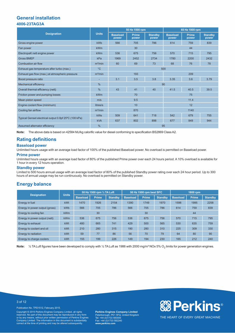
General installation4006-23TAG3A
Designation Units
50 Hz 1500 rpm 60 Hz 1800 rpm
Baseload power
Prime power
Standby power
Baseload power
Prime power
Standby power
Gross engine power kWb 566 705 786 614 759 839
Fan power kWm 30 44
ElectropaK nett engine power kWm 536 675 756 570 715 795
Gross BMEP kPa 1969 2452 2734 1780 2200 2432
Combustion air flow m³/min 60 69 73 68 76 78
Exhaust gas temperature after turbo (max.) °C 500
Exhaust gas flow (max.) at atmospheric pressure m³/min 193 209
Boost pressure ratio - 3.1 3.5 3.8 3.35 3.6 3.79
Mechanical efficiency % 90
Overall thermal efficiency (nett) % 43 41 40 41.5 40.5 39.5
Friction power and pumping losses kWm 70 75
Mean piston speed m/s 9.5 11.4
Engine coolant flow (minimum) litres/s 10 12
Cooling fan airflow m³/min 870 1140
Typical Genset electrical output 0.8pf 25ºC (100 kPa)kWe 509 641 718 542 679 755
kVA 637 802 898 677 849 944
Assumed alternator efficiency % 95
Note: The above data is based on 42584 MJ/kg calorific value for diesel conforming to specification BS2869 Class A2.
Rating definitionsBaseload powerUnlimited hours usage with an average load factor of 100% of the published Baseload power. No overload is permitted on Baseload power.
Prime powerUnlimited hours usage with an average load factor of 80% of the published Prime power over each 24 hours period. A 10% overload is available for 1 hour in every 12 hours operation.
Standby powerLimited to 500 hours annual usage with an average load factor of 80% of the published Standby power rating over each 24 hour period. Up to 300 hours of annual usage may be run continuously. No overload is permitted on Standby power.
Energy balance
Designation Units50 Hz 1500 rpm ½ TA Luft 50 Hz 1500 rpm best SFC 1800 rpm
Baseload Prime Standby Baseload Prime Standby Baseload Prime Standby
Energy in fuel kWt 1470 1926 2154 1390 1749 1970 1598 1995 2258
Energy in power output (gross) kWb 566 705 786 566 705 786 614 759 839
Energy to cooling fan kWm 30 30 44
Energy in power output (nett) kWm 536 675 756 536 675 756 570 715 795
Energy to exhaust kWt 480 665 741 429 500 565 530 635 759
Energy to coolant and oil kWt 210 280 315 190 280 310 225 309 330
Energy to radiation kWt 59 77 86 56 70 79 64 80 90
Energy to charge coolers kWt 155 199 226 149 194 230 165 212 240
Note: ½ TA Luft figures have been developed to comply with ½ TA Luft as 1986 with 2000 mg/m³ NOx 5% O2 limits for power generation engines.
Perkins Engines Company LimitedPeterborough, PE1 5FQ, United KingdomTel: +44 (0)1733 583000Fax: +44 (0)1733 582240www.perkins.com
Copyright © 2015 Perkins Engines Company Limited, all rights reserved. No part of this document may be reproduced in any form or by any means, without prior written permission of Perkins Engines Company Limited. The information in this document is substantially correct at the time of printing and may be altered subsequently.
4 of 12
Publication No. TPD1512, February 2015.
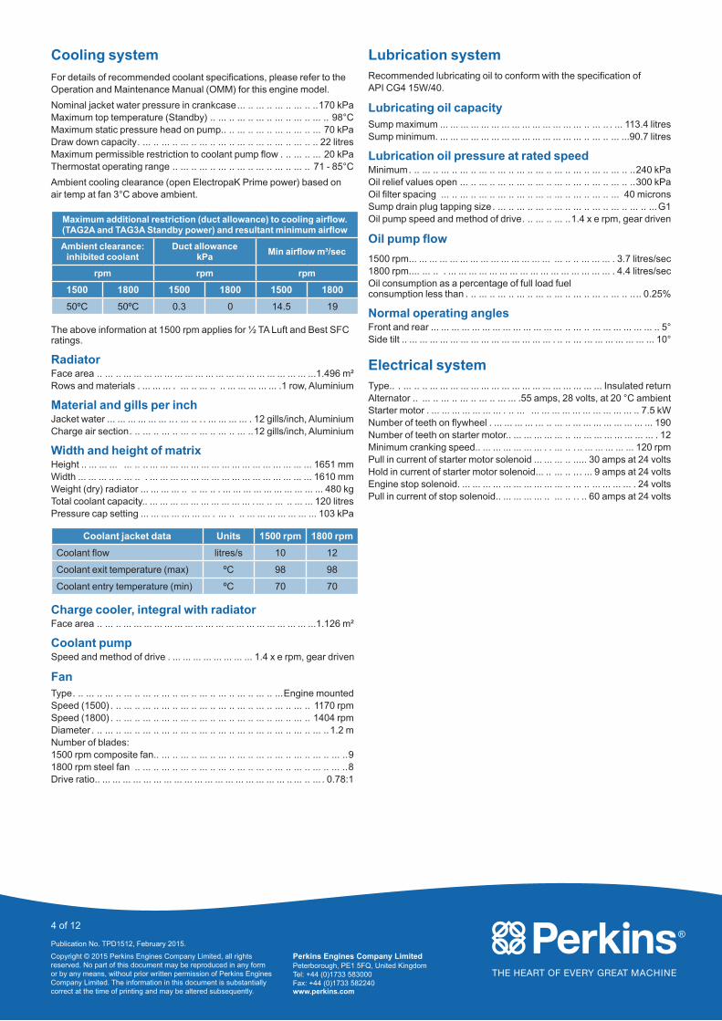
Cooling system
For details of recommended coolant specifications, please refer to the Operation and Maintenance Manual (OMM) for this engine model.
Nominal jacket water pressure in crankcase... .. ... .. ... .. ... .. ..170 kPaMaximum top temperature (Standby) .. ... .. ... .. ... .. ... .. ... .. ... .. 98°CMaximum static pressure head on pump.. .. ... .. ... .. ... .. ... .. ... 70 kPaDraw down capacity. ... .. ... .. ... .. ... .. ... .. ... .. ... .. ... .. ... .. .. 22 litresMaximum permissible restriction to coolant pump flow . .. ... .. ... 20 kPaThermostat operating range .. ... .. ... .. ... .. ... .. ... .. ... .. ... .. 71 - 85°C
Ambient cooling clearance (open ElectropaK Prime power) based on air temp at fan 3°C above ambient.
Maximum additional restriction (duct allowance) to cooling airflow. (TAG2A and TAG3A Standby power) and resultant minimum airflow
Ambient clearance: inhibited coolant
Duct allowance kPa
Min airflow m³/sec
rpm rpm rpm
1500 1800 1500 1800 1500 1800
50ºC 50ºC 0.3 0 14.5 19
The above information at 1500 rpm applies for ½ TA Luft and Best SFC ratings.
RadiatorFace area .. ... .. ... ... ... ... ... ... ... ... ... ... ... ... ... ... ... ... ... ... ...1.496 m²Rows and materials . ... ... ... . ... .. ... .. .. ... ... ... ... ... .1 row, Aluminium
Material and gills per inchJacket water ... ... ... ... ... ... .. . ... .. . . ... ... ... ... . 12 gills/inch, AluminiumCharge air section. .. ... .. ... .. ... .. ... .. ... .. ... ..12 gills/inch, Aluminium
Width and height of matrixHeight .. ... ... ... ... .. .. ... ... ... ... ... ... ... ... ... ... ... ... ... ... ... ... 1651 mmWidth ... ... ... .. .. ... .. . ... ... ... ... ... ... ... ... ... ... ... ... ... ... ... ... 1610 mmWeight (dry) radiator ... ... ... ... .. .. ... .. . ... ... ... ... ... ... ... ... ... ... 480 kgTotal coolant capacity.. ... ... ... ... ... ... ... ... ... ... . ... .. ... .. ... ... 120 litresPressure cap setting ... ... ... ... ... ... ... . ... .. .. ... ... ... ... ... ... ... 103 kPa
Coolant jacket data Units 1500 rpm 1800 rpm
Coolant flow litres/s 10 12
Coolant exit temperature (max) ºC 98 98
Coolant entry temperature (min) ºC 70 70
Charge cooler, integral with radiatorFace area .. ... .. ... ... ... ... ... ... ... ... ... ... ... ... ... ... ... ... ... ... ...1.126 m²
Coolant pumpSpeed and method of drive . ... ... ... ... .. . ... ... ... 1.4 x e rpm, gear driven
FanType. .. ... .. ... .. ... .. ... .. ... .. ... .. ... .. ... .. ... .. ... .. ...Engine mountedSpeed (1500) . .. ... .. ... .. ... .. ... .. ... .. ... .. ... .. ... .. ... .. ... .. 1170 rpmSpeed (1800) . .. ... .. ... .. ... .. ... .. ... .. ... .. ... .. ... .. ... .. ... .. 1404 rpmDiameter . .. ... .. ... .. ... .. ... .. ... .. ... .. ... .. ... .. ... .. ... .. ... .. ... ..1.2 mNumber of blades: 1500 rpm composite fan.. ... .. ... .. ... .. ... .. ... .. ... .. ... .. ... .. ... .. ... ..91800 rpm steel fan .. ... .. ... .. ... .. ... .. ... .. ... .. ... .. ... .. ... .. ... .. ... ..8Drive ratio.. ... ... ... ... ... ... ... ... ... ... ... ... ... ... ... ... ... ... .. ... .. ... . 0.78:1
Lubrication systemRecommended lubricating oil to conform with the specification of API CG4 15W/40.
Lubricating oil capacitySump maximum ... ... ... ... ... ... ... ... ... ... ... ... ... ... .. ... .. . ... 113.4 litresSump minimum. ... ... ... ... ... ... ... ... ... ... ... ... ... ... .. ... .. ... ...90.7 litres
Lubrication oil pressure at rated speedMinimum. .. ... .. ... .. ... .. ... .. ... .. ... .. ... .. ... .. ... .. ... .. ... .. ..240 kPaOil relief values open ... .. ... .. ... .. ... .. ... .. ... .. ... .. ... .. ... .. ..300 kPaOil filter spacing ... .. ... .. ... .. ... .. ... .. ... .. ... .. ... .. ... .. ... 40 micronsSump drain plug tapping size. ... .. ... .. ... .. ... .. ... .. ... .. ... .. ... .. ...G1Oil pump speed and method of drive. .. ... .. ... ..1.4 x e rpm, gear driven
Oil pump flow
1500 rpm... ... ... ... ... ... ... ... ... ... ... ... ... ... ... .. .. ... ... ... . 3.7 litres/sec1800 rpm.... ... .. . ... ... ... ... ... ... ... ... ... ... ... ... ... ... ... ... . 4.4 litres/secOil consumption as a percentage of full load fuel consumption less than . .. ... .. ... .. ... .. ... .. ... .. ... .. ... .. ... .. .... 0.25%
Normal operating anglesFront and rear ... ... ... ... ... ... ... ... ... ... ... ... ... .. ... .. ... ... ... ... ... ... .. 5°Side tilt .. ... ... ... ... ... ... ... ... ... ... ... ... ... ... . .. .. ... ... ... ... ... ... ... ... 10°
Electrical systemType.. . ... .. .. ... ... ... ... ... ... ... ... ... ... ... ... ... ... ... ... ... Insulated returnAlternator .. ... .. ... .. ... .. ... .. ... ... .55 amps, 28 volts, at 20 °C ambientStarter motor . ... ... ... ... ... ... ... . .. ... ... ... ... ... ... ... ... ... ... ... .. 7.5 kWNumber of teeth on flywheel . ... ... ... ... . .. .. ... .. ... ... ... ... ... ... ... ... 190Number of teeth on starter motor.. ... ... ... ... ... .. ... ... ... ... ... ... ... ... . 12Minimum cranking speed.. ... ... ... ... ... ... . . ... .. . .. ... ... ... ... ... 120 rpmPull in current of starter motor solenoid ... ... ... .. ..... 30 amps at 24 voltsHold in current of starter motor solenoid... .. ... .. ... ... 9 amps at 24 voltsEngine stop solenoid. ... ... ... ... ... ... ... ... ... ... .. ... .. ... ... ... ... . 24 voltsPull in current of stop solenoid.. ... ... ... ... .. ... .. .. .. 60 amps at 24 volts

Perkins Engines Company LimitedPeterborough, PE1 5FQ, United KingdomTel: +44 (0)1733 583000Fax: +44 (0)1733 582240www.perkins.com
Copyright © 2015 Perkins Engines Company Limited, all rights reserved. No part of this document may be reproduced in any form or by any means, without prior written permission of Perkins Engines Company Limited. The information in this document is substantially correct at the time of printing and may be altered subsequently.
5 of 12
Publication No. TPD1512, February 2015.
Starting requirements
Temperature range
To 10 ºC (50 ºF)
Oil: CG4 15w/40
Starter: 1 x 24 volts
Battery 2 x 12v x Ah 143
Max. breakawayCurrent 1000 ampsCranking current 600 amps
Aids Not required
Note: The battery capacity is defined by the 20 hour rate at 0 °C.
Note: The oil specification should be for the minimum ambient temperature as the oil will not be warned by the immersion heater.
Note: The breakaway current is dependant on the battery capacity available. Cables should be capable of handling the transient current which may be up to double the steady cranking current.
Fuel systemRecommended fuel to conform to . ... .. ... .. BS2869 1998 Class A1, A2Type of injection system .. ... ... ... ... ... ... ... ... ... ... .. . ... Direct injectionFuel injector . ... ... ... ... ... ... ... ... .. ... .. . . ... ... ... Combined unit injectorInjector pressure... .. 220 ATS (NOP) 1400 bar max. operating pressureDelivery at 1500 rpm ... .. ... .. ... .. ... .. ... .. ... .. ... .. ... .. 630 litres/hourDelivery at 1800 rpm ... .. ... .. ... .. ... .. ... .. ... .. ... .. ... .. 810 litres/hourFuel delivery pump pressure.. ... .. ... .. ... .. ... .. ... .. ... .. ... .. ..250 kPaFuel lift pump maximum suction head.. ... .. ... .. ... .. ... .. ... .. ... ..2.5 mFuel return maximum pressure head .. ... .. ... .. ... .. ... .. ... see manualFuel filter spacing .. .. ... .. ... .. ... .. ... .. ... .. ... .. ... .. ... .. ... 10 micronsGovernor type .. ... .. ... .. ... .. ... .. ... .. ... .. ... .. ... .. ... .. ... ..Electronic
Fuel consumption gross (½ TA Luft)
4006-23TAG2Ag/kWh litres/hr
1500 1800
Standby 213 178
Prime 213 163
Baseload 215 133
75% prime 215 124
50% prime 219 84
4006-23TAG3Ag/kWh litres/hr
1500 1800
Standby 222 203
Prime 214 175
Baseload 207 139
75% prime 213 132
50% prime 213 88
Note: All figures based on gross mechanical output, for fuel consumption based on electrical output of the generating set contact your OEM.
Fuel consumption gross (best SFC)
4006-23TAG2Ag/kWh litres/hr
1500 1800 1500 1800
Standby 210 228 176 196
Prime 210 224 161 176
Baseload 212 212 131 135
75% prime 213 214 122 126
50% prime 218 224 83 88
4006-23TAG3Ag/kWh litres/hr
1500 1800 1500 1800
Standby 212 230 194 224
Prime 210 226 172 200
Baseload 208 213 137 152
75% prime 210 214 130 144
50% prime 213 205 90 96
Note: All figures based on gross mechanical output, for fuel consumption based on electrical output of the generating set contact your OEM.
Induction systemMaximum air intake restriction of engineClean filter. ... ... ... ... ... ... ... ... ... ... ... ... ... ... ... ... .. ... .. .. . ... 1.25 kPaDirty filter... ... ... ... ... ... ... ... ... ... ... ... ... .. . ... .. ... .. ... . ... ... ... 3.7 kPaAir filter type .. ... ... ... ... ... ... ... ... ... .. . ... .. . ... ... ... ... ... ... . Dry, paper
Exhaust systemExhaust outlet size (internal). ... ... ... ... ... ... ... . ... .. ... ... 2 x 152.4 mm
Exhaust back pressure for total systemTAG2A .. ... ... ... ... ... ... ... ... ... ... ... ... ... ... ... ... ... .. ... .. ... .. . ... 6 kPaTAG3A .. ... ... ... ... ... ... ... ... ... ... ... ... ... .. ... .. ... .. ... .... ... ... ... 6 kPa
Note: For recommended pipe sizes see the Installation Manual.
Engine mountingMaximum additional load applies to flywheel due to all rotating components .. ... ... ... ... ... ... ... ... ... ... ... ... ... ... ... ... ... . ... .. .. ..650 kg
Position of engine centre of gravity (wet):Forward of the rear face of the crankcase ... ... ... .. .. ... .. . ... ... 625 mmAbove the crankshaft centre line.. ... ... ... ... ... ... . . .. ... .... ... ... 140 mm

Perkins Engines Company LimitedPeterborough, PE1 5FQ, United KingdomTel: +44 (0)1733 583000Fax: +44 (0)1733 582240www.perkins.com
Copyright © 2015 Perkins Engines Company Limited, all rights reserved. No part of this document may be reproduced in any form or by any means, without prior written permission of Perkins Engines Company Limited. The information in this document is substantially correct at the time of printing and may be altered subsequently.
6 of 12
Publication No. TPD1512, February 2015.
Load acceptance (cold)
At 1500 rpm
Initial load acceptance when engine reaches rated speed (15 seconds maximum after engine starts to crank)
2nd load application immediately after engine has recovered to rated speed (5 seconds after initial load application)
Engine TypePrime
power %Load kWm nett / kWe
Transient frequency
deviation %
Frequency recovery
time seconds
Prime power %
Load kWm nett / kWe
Transient frequency
deviation %
Frequency recovery
time seconds
4006-23TAG2A 67 421 / 400 ≤ -10 5 33 211 / 200 ≤ -10 5
4006-23TAG3A 66 448 / 421 ≤ -10 5 34 231 / 219 ≤ -10 5
At 1800 rpm
Initial load acceptance when engine reaches rated speed (15 seconds maximum after engine starts to crank)
2nd load application immediately after engine has recovered to rated speed (5 seconds after initial load application)
Engine TypePrime
power %Load kWm nett / kWe
Transient frequency
deviation %
Frequency recovery
time seconds
Prime power %
Load kWm nett / kWe
Transient frequency
deviation %
Frequency recovery
time seconds
4006-23TAG2A 70 446 / 420 ≤ -10 5 30 192 / 180 ≤ -10 5
4006-23TAG3A 67 483 / 454 ≤ -10 5 33 232 / 221 ≤ -10 5
The above complies with requirements of Classification 3 & 4 of ISO 8528-12 and G2 operating limits stated in ISO 8528-5.
The above figures were obtained under test conditions as follows:
Engine block temperature ... ... ... ... ... ... ... ... ... ... ... ... ... ... ... ... ... ... ... ... ... ... ... ... ... ... ... ... ... ... ... ... ... ... ... ... ... ... ... ... ... .. ... .. ... .. . . 45 °CAlternator efficiency .. ... .. ... .. ... .. ... .. ... .. ... .. ... .. ... .. ... .. ... .. ... .. ... .. ... .. ... .. ... .. ... .. ... .. ... .. ... .. ... .. ... .. ... .. ... .. ... .. ... .. ... .. ... 94 %Minimum ambient temperature ... .. ... .. ... .. ... .. ... .. ... .. ... .. ... .. ... .. ... .. ... .. ... .. ... .. ... .. ... .. ... .. ... .. ... .. ... .. ... .. ... .. ... .. ... .. ... .. ... 10 °C
Isochronous governingUnder frequency roll off (UFRO) set to .. ... .. ... .. ... .. ... .. ... .. ... .. ... .. ... .. ... .. ... .. ... .. ... .. ... .. ... .. ... .. ... .. ... .. ... 1 Hz below rated frequencyTypical alternator inertia .. ... .. ... .. ... .. ... .. ... .. ... .. ... .. ... .. ... .. ... .. ... .. ... .. ... .. ... .. ... .. ... .. ... .. ... .. ... .. ... .. ... .. ... .. ... .. ... .. ... .. 20 kgm²
All tests were conducted using an engine installed and serviced to Perkins Engine Company Limited recommendations.
The information given on this Technical Data Sheet is for standard engines, and for guidance only. For ratings other than shown contact the Applications Department.
Perkins Engines Company LimitedPeterborough, PE1 5FQ, United KingdomTel: +44 (0)1733 583000Fax: +44 (0)1733 582240www.perkins.com
Copyright © 2015 Perkins Engines Company Limited, all rights reserved. No part of this document may be reproduced in any form or by any means, without prior written permission of Perkins Engines Company Limited. The information in this document is substantially correct at the time of printing and may be altered subsequently.
7 of 12
Publication No. TPD1512, February 2015.
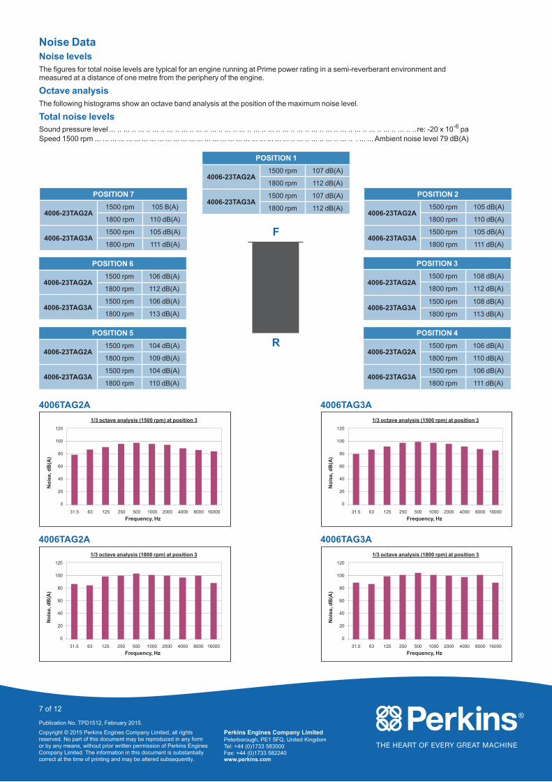
Noise DataNoise levelsThe figures for total noise levels are typical for an engine running at Prime power rating in a semi-reverberant environment and measured at a distance of one metre from the periphery of the engine.
Octave analysisThe following histograms show an octave band analysis at the position of the maximum noise level.
Total noise levelsSound pressure level ... .. ... .. ... .. ... .. ... .. ... .. ... .. ... .. ... .. ... .. ... .. ... .. ... .. ... .. ... .. ... .. ... .. ... .. ... .. ... .. ... .. .. re: -20 x 10-6 paSpeed 1500 rpm ... ... ... ... ... ... ... ... ... ... ... ... ... ... ... ... ... ... ... ... ... ... ... ... ... .. ... .. ... .. ... .. ... .. . ... ... Ambient noise level 79 dB(A)
POSITION 1
4006-23TAG2A1500 rpm 107 dB(A)
1800 rpm 112 dB(A)
4006-23TAG3A1500 rpm 107 dB(A)
1800 rpm 112 dB(A)
POSITION 2
4006-23TAG2A1500 rpm 105 dB(A)
1800 rpm 110 dB(A)
4006-23TAG3A1500 rpm 105 dB(A)
1800 rpm 111 dB(A)
POSITION 7
4006-23TAG2A1500 rpm 105 B(A)
1800 rpm 110 dB(A)
4006-23TAG3A1500 rpm 105 dB(A)
1800 rpm 111 dB(A)
POSITION 3
4006-23TAG2A1500 rpm 108 dB(A)
1800 rpm 112 dB(A)
4006-23TAG3A1500 rpm 108 dB(A)
1800 rpm 113 dB(A)
POSITION 6
4006-23TAG2A1500 rpm 106 dB(A)
1800 rpm 112 dB(A)
4006-23TAG3A1500 rpm 106 dB(A)
1800 rpm 113 dB(A)
POSITION 4
4006-23TAG2A1500 rpm 106 dB(A)
1800 rpm 110 dB(A)
4006-23TAG3A1500 rpm 106 dB(A)
1800 rpm 111 dB(A)
POSITION 5
4006-23TAG2A1500 rpm 104 dB(A)
1800 rpm 109 dB(A)
4006-23TAG3A1500 rpm 104 dB(A)
1800 rpm 110 dB(A)
4006TAG2A
1/3 octave analysis (1500 rpm) at position 3
Frequency, Hz
No
ise,
dB
(A)
120
100
80
60
40
20
0
31.5 63 125 250 500 1000 2000 4000 8000 16000
4006TAG2A
1/3 octave analysis (1800 rpm) at position 3
Frequency, Hz
No
ise,
dB
(A)
120
100
80
60
40
20
0
31.5 63 125 250 500 1000 2000 4000 8000 16000
4006TAG3A
1/3 octave analysis (1500 rpm) at position 3
Frequency, Hz
No
ise,
dB
(A)
120
100
80
60
40
20
0
31.5 63 125 250 500 1000 2000 4000 8000 16000
4006TAG3A
1/3 octave analysis (1800 rpm) at position 3
Frequency, Hz
No
ise,
dB
(A)
120
100
80
60
40
20
0
31.5 63 125 250 500 1000 2000 4000 8000 16000
F
R

Perkins Engines Company LimitedPeterborough, PE1 5FQ, United KingdomTel: +44 (0)1733 583000Fax: +44 (0)1733 582240www.perkins.com
Copyright © 2015 Perkins Engines Company Limited, all rights reserved. No part of this document may be reproduced in any form or by any means, without prior written permission of Perkins Engines Company Limited. The information in this document is substantially correct at the time of printing and may be altered subsequently.
8 of 12
Publication No. TPD1512, February 2015.
4006-23TAG2A/3A - Left side view
1493
RE
AR
FA
CE
OF
FLY
WH
EE
L H
SG
FR
ON
T F
AC
E O
F
CR
AN
KC
AS
E
539
CE
NT
RE
OF
G
RA
VIT
YE
NG
INE
&
RA
DIA
TO
R (
WE
T)
1650
.6
220
EN
GIN
E
MO
UN
TIN
GF
EE
T
25
2927
OV
ER
ALL
LE
NG
TH
2125
OV
ER
ALL
H
EIG
HT
1124
1380
.5
2106
1034
730
25
582
827
316
AIR
FLO
W
LEF
T S
IDE
ELE
VA
TIO
N
CR
AN
KS
HA
FT
TIM
ING
MA
RK
VIE
WIN
G H
OLE
EX
HA
US
T O
UT
LET
SN
OT
E: C
US
TO
ME
R C
ON
NE
CT
ION
MU
ST
BE
SU
FF
ICIE
NT
LY S
UP
PO
RT
ED
TO
EN
SU
RE
TH
AT
NO
LO
AD
ISP
LAC
ED
ON
TU
RB
OC
HA
RG
ER
S
FU
EL
CO
OLE
RC
ON
NE
CT
ION
S G
3/4
FU
EL
RE
TU
RN
CO
NN
EC
TIO
NT
O S
UIT
15
OU
TS
IDE
ST
EE
L T
UB
E
FA
N B
ELT
TE
NS
ION
ER
SC
RE
W
FA
N G
UA
RD
BE
LT G
UA
RD
AN
D D
AM
PE
RG
UA
RD
SH
OW
NC
HA
IN-D
OT
TE
D
EN
GIN
E B
RE
AT
HE
R O
UT
LET
50.8
(2
INC
H)
INS
IDE
HO
SE
HIG
H W
AT
ER
TE
MP
ER
AT
UR
E P
RO
TE
CT
ION
SW
ITC
H
27 H
OLE
- F
RO
NT
LIF
TIN
G B
RA
CK
ET
(EN
GIN
E O
NLY
)

Perkins Engines Company LimitedPeterborough, PE1 5FQ, United KingdomTel: +44 (0)1733 583000Fax: +44 (0)1733 582240www.perkins.com
Copyright © 2015 Perkins Engines Company Limited, all rights reserved. No part of this document may be reproduced in any form or by any means, without prior written permission of Perkins Engines Company Limited. The information in this document is substantially correct at the time of printing and may be altered subsequently.
9 of 12
Publication No. TPD1512, February 2015.
4006-23TAG2A/3A - Front view
570
CRANKSHAFT
882
220ENGINE
MOUNTINGS
383
200
200
200
200
200
200
200
16 X 11
1659.5 CRS
832
1689.5OVERALL WIDTH
847
10
175
1610 MATRIX
1651MATRIX
252FUEL RETURNCONNECTION
FRONT ELEVATION
24V DC STOP SOLENOID(ENERGISED TO RUN)
MANUAL STOP LEVER
CRANKSHAFT
FUEL INLET CONNECTIONTO SUIT 15 OUTSIDE STEEL TUBE
IF FUEL TANK OUTLET IS LOWER THANLIFT PUMP INLET A NON-RETURN VALVEMUST BE FITTED AT FUEL TANK OUTLET
MAXIMUM LIFT = 2.5M
RADIATOR FILLER CAP
LIFITING EYE - CRANKSHAFT
B

Perkins Engines Company LimitedPeterborough, PE1 5FQ, United KingdomTel: +44 (0)1733 583000Fax: +44 (0)1733 582240www.perkins.com
Copyright © 2015 Perkins Engines Company Limited, all rights reserved. No part of this document may be reproduced in any form or by any means, without prior written permission of Perkins Engines Company Limited. The information in this document is substantially correct at the time of printing and may be altered subsequently.
10 of 12
Publication No. TPD1512, February 2015.
4006-23TAG2A/3A - Right side view
441.
5
FR
ON
T F
AC
EC
RA
NK
CA
SE
517.
2(O
IL D
RA
IN)
228.
6 (9
-IN
CH
) O
UT
SID
E A
IRC
LEA
NE
R IN
LET
3
238
(FU
EL
INLE
T)
FU
EL
FIL
TE
RW
AT
ER
SE
PA
RA
TO
R
RIG
HT
SID
E E
LEV
AT
ION
AIR
FIL
TE
R2
OF
F
LUB
RIC
AT
ING
OIL
LEV
EL
IND
ICA
TO
R
3/8
NP
SF
LUB
RIC
AT
ING
OIL
TE
MP
ER
AT
UR
E C
ON
NE
CT
ION
ST
AR
TE
R R
ELA
Y
LUB
RIC
AT
ING
OIL
F
ILT
ER
- 3
OF
F
CE
NT
RE
-LIN
EC
RA
NK
SH
AF
T
GI L
UB
RIC
AT
ING
OIL
DR
AIN
(B
OT
H S
IDE
S)
FU
EL
LIF
T P
UM
PRA
DIA
TO
R
24V
DC
E
LEC
TR
IC S
TA
RT
ER
1/8
NP
SF
LUB
RIC
AT
ING
OIL
PR
ES
SU
RE
CO
NN
EC
TIO
N
24V
DC
ALT
ER
NA
TO
R
FU
EL
INLE
TC
ON
NE
CT
ION
LUB
RIC
AT
ING
OIL
FIL
LER
G3/
8LU
BR
ICA
TIN
G O
ILC
ON
NE
CT
ION
FA
N B
ELT
INS
PE
CT
ION
CO
VE
R
FU
EL
HA
ND
PR
IMIN
G P
UM
P
DU
CT
FIX
ING
FA
CE

Perkins Engines Company LimitedPeterborough, PE1 5FQ, United KingdomTel: +44 (0)1733 583000Fax: +44 (0)1733 582240www.perkins.com
Copyright © 2015 Perkins Engines Company Limited, all rights reserved. No part of this document may be reproduced in any form or by any means, without prior written permission of Perkins Engines Company Limited. The information in this document is substantially correct at the time of printing and may be altered subsequently.
11 of 12
Publication No. TPD1512, February 2015.
4006-23TAG2A/3A - Rear view
A
A406AIRFILTERELEMENTREMOVAL
68SUMPREMOVAL
140
549
650
CRANKSHAFT
650
645 EXHAUST OUTLETS 786
1755
16 X M12 X 1.75 X 21 EQUI-SPACED ON 679.45 PC(26.75-INCH)
6 X M16 X 2.0 X 30 EQUI-SPACED ON 542.93 PC(21.375-INCH)
181
1999OVERALL
2 X 17.5
359SUMP WIDTH
(MAX)
CRANKSHAFT
REAR ELEVATION
30 LIFTING HOLEENGINE ONLY - 1 EACH SIDE
AIR CLEANERS MUST BE REMOVEDFOR USE
LIFTING BRACKET MAY BE REMOVEDWHEN NOT REQUIRED
TURBOCHARGERS
G1/2 VENT
G 1/2 DRAIN
CRANKSHAFT ROTATION
RADIATOR REMOVABLELIFITNG EYES
Perkins Engines Company LimitedPeterborough, PE1 5FQ, United KingdomTel: +44 (0)1733 583000Fax: +44 (0)1733 582240www.perkins.com
Copyright © 2015 Perkins Engines Company Limited, all rights reserved. No part of this document may be reproduced in any form or by any means, without prior written permission of Perkins Engines Company Limited. The information in this document is substantially correct at the time of printing and may be altered subsequently.
12 of 12
Publication No. TPD1512, February 2015.
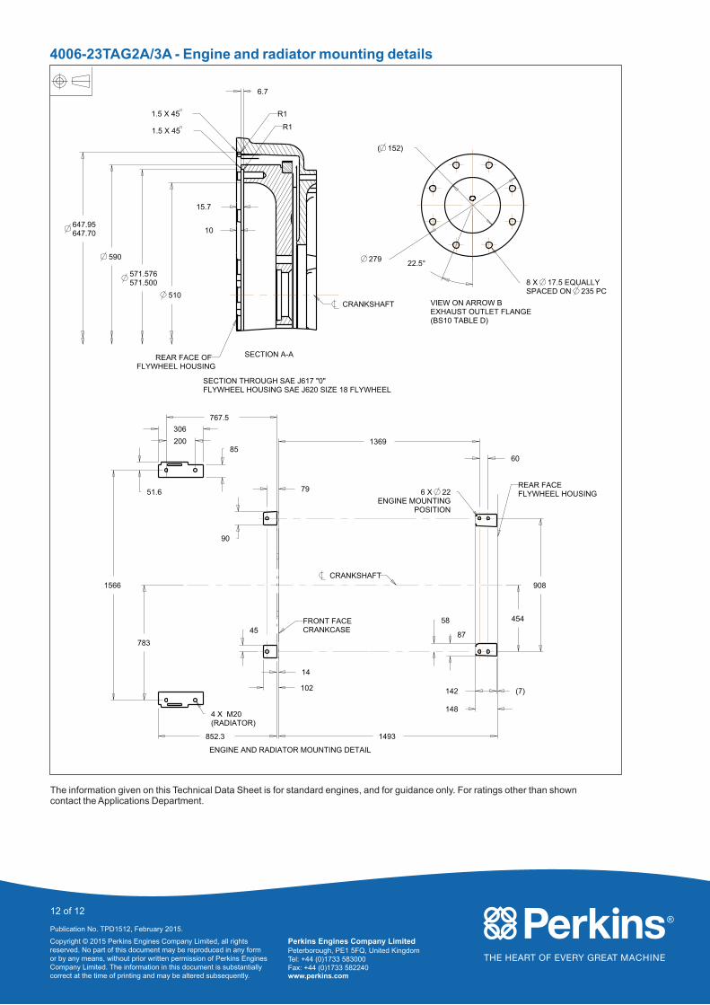
4006-23TAG2A/3A - Engine and radiator mounting details
767.5
1369
60
454
908
783
1566
51.6
306
85
852.3 1493
148
279
200
90
4 X M20(RADIATOR)
POSITIONENGINE MOUNTING
226 X 79
45
142
87
58
6.7
10
15.7
510
571.576571.500
590
647.95647.70
14
102 (7)
( 152)
8 X 17.5 EQUALLYSPACED ON 235 PC
22.5°
FRONT FACECRANKCASE
CRANKSHAFT
REAR FACEFLYWHEEL HOUSING
ENGINE AND RADIATOR MOUNTING DETAIL
VIEW ON ARROW BEXHAUST OUTLET FLANGE (BS10 TABLE D)
1.5 X 45 R1
R11.5 X 45
SECTION THROUGH SAE J617 "0" FLYWHEEL HOUSING SAE J620 SIZE 18 FLYWHEEL
SECTION A-A
CRANKSHAFT
REAR FACE OFFLYWHEEL HOUSING
The information given on this Technical Data Sheet is for standard engines, and for guidance only. For ratings other than shown contact the Applications Department.