52512003 Steel Bridges
96
Publication No. 34/02 Steel Bridges
-
Upload
dragan-gligorov -
Category
Documents
-
view
228 -
download
1
Transcript of 52512003 Steel Bridges

8/7/2019 52512003 Steel Bridges
http://slidepdf.com/reader/full/52512003-steel-bridges 1/96
Publication No. 34/02
Steel Bridges

8/7/2019 52512003 Steel Bridges
http://slidepdf.com/reader/full/52512003-steel-bridges 2/96
A Practical Approach to Design for Efficient Fabrication and Construction
By Alan Hayward, Neil Sadler and Derek Tordoff
Steel Bridges
Publication Number 34/02
8/7/2019 52512003 Steel Bridges
http://slidepdf.com/reader/full/52512003-steel-bridges 3/96
Apart from any fair dealing for the purposes of research or
private study or criticism or review, as permitted under the
Copyright Design and Patents Act 1988, this publication may
not be reproduced, stored or transmitted in any form by anymeans without the prior permission of the publishers or in the
case of reprographic reproduction only in accordance with the
terms of the licences issued by the UK Copyright Licensing
Agency, or in accordance with the terms of licences issued by
the appropriate Reproduction Rights Organisation outside the
UK.
Enquiries concerning reproduction outside the terms stated
here should be sent to the publishers, The British
Constructional Steelwork Association Ltd at the address given
below.
Although care has been taken to ensure, to the best of our
knowledge, that all data and information contained herein are
accurate to the extent that they relate to either matters of fact
or accepted practice or matters of opinion at the time of publication, The British Constructional Steelwork Association
Ltd, the authors and the reviewers assume no responsibility
for any errors in or misinterpretation of such data and/or
information or any loss or damage arising from or related to
their use.
The British Constructional Steelwork Association Limited
(BCSA) is the national organisation for the steel construction
industry: its Member companies undertake the design,
fabrication and erection of steelwork for all forms of construction in building and civil engineering. Associate
Members are those principal companies involved in the
purchase, design or supply of components, materials,
services related to the industry. Corporate Members are
clients, professional offices, educational establishments which
support the development of national specifications, quality,
fabrication and erection techniques, overall industry efficiency
and good practice.
The principal objectives of the Association are to promote the
use of structural steelwork; to assist specifiers and clients; to
ensure that the capabilities and activities of the industry are
widely understood and to provide members with professional
services in technical, commercial, contractual and quality
assurance matters. The Association’s aim is to influence the
trading environment in which member companies operate in
order to improve their profitability.
A current list of members and a list of current publications and
further membership details can be obtained from:
The British Constructional Steelwork Association Ltd
4 Whitehall Court, Westminster, London SW1A 2ES
Telephone: +44 (0) 20 7839 8566
Fax: +44 (0) 20 7976 1634
Email: [email protected]
BCSA’s website, www.SteelConstruction.org, can be
used both to find information about steel construction
companies and suppliers, and also to search for advice
and information about steel construction related topics,
view publications, etc.
Publication Number 34/02
First Edition March 1985
Second Impression March 1990
Third Impression April 1991
Second Edition December 2002
ISBN 0 85073 040 6
British Library Cataloguing-in-Publication Data
A catalogue record for this book is available from the
British Library
© The British Constructional Steelwork Association Ltd
Designed and Printed by Box of Tricks www.bot.uk.com

8/7/2019 52512003 Steel Bridges
http://slidepdf.com/reader/full/52512003-steel-bridges 4/96
PREFACE TO THE SECOND EDITION
Design of steel bridges is achieved most effectivelywhen it is based on a sound understanding of both the
material and the methods adopted in processing
steelwork through to the final bridge form. The aim of
this publication is to provide a basis for this
understanding by reference to the factors which
influence safe, practical and economic fabrication and
erection of bridge steelwork.
The first edition of this publication was prompted by
the need for the steel construction industry to give
general guidance and information to designers of small
and medium span steel bridges in the UK and was to
provide an insight into the practical aspects of fabrication and erection that would help designers use
steel more efficiently and economically to achieve their
clients' requirements. That need is just as vital today,
but since publication of the first edition in 1985 many
changes in working practice have occurred that make
a second edition essential.
The text has been amended and updated to reflect
changes in procurement practice, the continuing
European harmonisation of codes and standards,
technological advances in manufacturing and
construction, and modernisation of fabrication
workshops. The original structure of the content hasbeen retained: Chapters 1, 2 and 3 provide guidance
on conceptual design, steel quality, and design of
members; Chapters 4 and 6 give practical information
on bolting and welding for connections, and on
procedures for managing them in implementing the
design; Chapter 5 discusses the accuracy of
fabrication and its significance for the designer; some
guidance on cost is given in Chapter 7 in qualitative
terms. The guidance is supported with a new set of
case studies illustrating 'good' deck layouts and cross-
section arrangements, fabrication details and
economic design solutions for some recent specific
bridge requirements. A substantial reference list is
included so that the reader may follow up the subject
in greater depth to meet his particular needs.
Throughout the text there are many references toCodes of Practice, British Standards and other design
documents – particularly the standards and advice
notes contained in the Design Manual for Roads and
Bridges issued on behalf of the highways overseeing
organisation in England, Scotland, Wales and Northern
Ireland. In a period of considerable change, the
references relate to documents current in 2002, and
their antecedents where relevant. Change will go on
and in the life of this edition it is probable that the
Eurocodes will be implemented. Given that most of the
guidance and information is practical and
technological, the reader should be confident in
making continued use of the publication provided he
has an awareness of changes in requirements which
affect responsibilities, procedural arrangements, or
quantitative values eg fabrication tolerances.
This second edition has been prepared by Cass
Hayward & Partners for the BCSA, with substantial
input from Alan C G Hayward and Neil Sadler; Alan
Hayward also made significant contribution to the
original text. Thanks are given to Ian E Hunter,
Consultant - formerly Cleveland Bridge Ltd, for drafting
parts of the text and an overall editorial review, and to
Richard Thomas of Rowecord Engineering Ltd for
drafting Chapter 6. The valued assistance of the
following is also acknowledged:
C V Castledine formerly Butterley Engineering Ltd
J Dale Rowecord Engineering Ltd
N Iannetta Fairfield-Mabey Ltd
A Jandu Highways Agency
P Lloyd Fairfield-Mabey Ltd
G M Mitchell MBE BCSA
S Waters Fairfield-Mabey Ltd
P J Williams BCSA
STEEL BRIDGES A Practical Approach to Design for Efficient Fabrication and Construction
8/7/2019 52512003 Steel Bridges
http://slidepdf.com/reader/full/52512003-steel-bridges 5/96
PREFACE TO THE FIRST EDITION (Reproduced)
The aim of this publication is to provide guidance upon
the practical aspects of fabrication that influence theefficient design of steel bridges. Extensive consultation
has taken place with experts in the design, fabrication
and erection of steel bridges and therefore this
publication represents a compilation of many years’
knowledge and experience.
The proof of the effectiveness of this approach is that
a number of steel bridge designs based on these
concepts have proved to be less expensive than the
more traditional designs in concrete and steel.
References are made to BS 5400 Part 3 (Code of
practice for the design of steel bridges) and Part 6
(Specification for materials and workmanship, steel)and their application in practice is demonstrated.
Examples are given of ‘good’ deck layouts and cross
sectional arrangements, fabrication details and
economic design solutions to specific bridge
requirements.
The author, Derek Tordoff, has worked on the design,
construction and inspection of steel and concrete
bridges both with consultants and with a contractor.
He undertook research work at the University of Leeds
on computer aided techniques for the efficient design
of steel bridges. He joined BCSA in 1976 where he is
now Director General with wide ranging responsibilities
in the steel construction industry
ACKNOWLEDGEMENTS
(First Edition - reproduced)
The author is indebted to JS Allen (NEI Thompson Ltd)
and ACG Hayward (Cass Hayward & Partners) for their
comments, advice and contributions to
the text.
Acknowledgements for their assistance are also
due to:
P H Allen BCSA
J G Booth John Booth & Sons (Bolton) Ltd
Prof F M Burdekin University of Manchester Institute
of Science & Technology
M M Chrimes Institution of Civil Engineers
W R Cox Sir William Arrol NEI Cranes Ltd
K Dixon Cleveland Bridge and Engineering
J E Evans ex Fairfield Mabey Ltd
H J Gettins Robert Watson & Co
(Constructional Engineers) Ltd
A N Hakin BCSA
J Kinsella Dorman Long Bridge
& Engineering
F I Lees Butterley Engineering Ltd
J E Leeson NEI Thompson Ltd
Horseley BridgeJ W Pask ex Redpath Dorman Long Ltd
J L Pratt Braithwaite & Co (Structural) Ltd
W R Ramsay BSC Sections and
Commercial Steels
D C Shenton BSC Sections and
Commercial Steels
T J Upstone ex Redpath Dorman Long Ltd
F G Ward ex Constrado
A Waterhouse NEI Thompson Ltd
Horseley Bridge
The diagrams, charts and figures have been preparedwith the assistance of Cass Hayward & Partners.
8/7/2019 52512003 Steel Bridges
http://slidepdf.com/reader/full/52512003-steel-bridges 6/96
1. Design Conception
1.1 Introduction . . . . . . . . . . . . . . . . . . . . . . . . . . . . . . . . . . . . . 11.2 Initial Conception . . . . . . . . . . . . . . . . . . . . . . . . . . . . . . . . . 2
1.3 Cross-Sections for Highway Bridges . . . . . . . . . . . . . . . . . . . 4
1.4 Cross-Sections for Railway Bridges . . . . . . . . . . . . . . . . . . . . 91.5 Cross-Sections for Footbridges. . . . . . . . . . . . . . . . . . . . . . 11
1.6 Camber . . . . . . . . . . . . . . . . . . . . . . . . . . . . . . . . . . . . . . . 11
1.7 Dimensional Limitations. . . . . . . . . . . . . . . . . . . . . . . . . . . . 13
1.8 Erection . . . . . . . . . . . . . . . . . . . . . . . . . . . . . . . . . . . . . . . 14
1.9 Repairs and Upgrading . . . . . . . . . . . . . . . . . . . . . . . . . . . . 15
2. Steel Qualities2.1 Introduction . . . . . . . . . . . . . . . . . . . . . . . . . . . . . . . . . . . . 17
2.2 Brittle Fracture and Notch Toughness Requirements. . . . . . . 17
2.3 Internal Discontinuities in Rolled Steel Products . . . . . . . . . . 172.4 Material Selection . . . . . . . . . . . . . . . . . . . . . . . . . . . . . . . . 19
2.5 Weathering Steels. . . . . . . . . . . . . . . . . . . . . . . . . . . . . . . . 20
2.5.1 Performance. . . . . . . . . . . . . . . . . . . . . . . . . . . . . . . . . . . . 20
2.5.2 Materials and Weldability. . . . . . . . . . . . . . . . . . . . . . . . . . . 21
2.5.3 Bolting . . . . . . . . . . . . . . . . . . . . . . . . . . . . . . . . . . . . . . . . 21
2.5.4 Availability of Weathering Steel . . . . . . . . . . . . . . . . . . . . . . 22
2.5.5 Suitability . . . . . . . . . . . . . . . . . . . . . . . . . . . . . . . . . . . . . . 22
3. Design of Members3.1 Introduction . . . . . . . . . . . . . . . . . . . . . . . . . . . . . . . . . . . . 23
3.2 Plate Girders . . . . . . . . . . . . . . . . . . . . . . . . . . . . . . . . . . . 23
3.3 Box Girders . . . . . . . . . . . . . . . . . . . . . . . . . . . . . . . . . . . . 25
3.4 Bearings . . . . . . . . . . . . . . . . . . . . . . . . . . . . . . . . . . . . . . 26
4. Connections4.1 Introduction . . . . . . . . . . . . . . . . . . . . . . . . . . . . . . . . . . . . 33
4.2 Bolted Connections . . . . . . . . . . . . . . . . . . . . . . . . . . . . . . 33
4.3 High Strength Friction Grip Bolts . . . . . . . . . . . . . . . . . . . . . 33
4.4 The Friction Grip Joint. . . . . . . . . . . . . . . . . . . . . . . . . . . . . 33
4.5 Installation of HSFG Bolts . . . . . . . . . . . . . . . . . . . . . . . . . . 34
4.5.1 Torque Control . . . . . . . . . . . . . . . . . . . . . . . . . . . . . . . . . . 34
4.5.2 Part-Turn Method . . . . . . . . . . . . . . . . . . . . . . . . . . . . . . . . 34
4.5.3 Direct Tension Indication . . . . . . . . . . . . . . . . . . . . . . . . . . . 34
4.5.4 Sequence of Tightening . . . . . . . . . . . . . . . . . . . . . . . . . . . 35
4.6 Inspection of HSFG Bolts . . . . . . . . . . . . . . . . . . . . . . . . . . 35
4.7 Welded Connections. . . . . . . . . . . . . . . . . . . . . . . . . . . . . . 35
5. Fabrication5.1 Introduction . . . . . . . . . . . . . . . . . . . . . . . . . . . . . . . . . . . . 37
5.2 Fabrication Tolerances . . . . . . . . . . . . . . . . . . . . . . . . . . . . 38
5.3 Checking of Deviations . . . . . . . . . . . . . . . . . . . . . . . . . . . . 38
5.4 Causes of Fabrication Distortion . . . . . . . . . . . . . . . . . . . . . 42
5.5 Methods of Control of Distortion . . . . . . . . . . . . . . . . . . . . . 42
5.6 Effects of Design on Distortion. . . . . . . . . . . . . . . . . . . . . . . 42
5.7 Distortion Effects and Control of
Various Forms of Construction. . . . . . . . . . . . . . . . . . . . . . . 43
5.8 Correction of Distortion . . . . . . . . . . . . . . . . . . . . . . . . . . . . 43
5.9 Trial Erection. . . . . . . . . . . . . . . . . . . . . . . . . . . . . . . . . . . . 43
CONTENTS

8/7/2019 52512003 Steel Bridges
http://slidepdf.com/reader/full/52512003-steel-bridges 7/96
6. Welding6.1 Introduction . . . . . . . . . . . . . . . . . . . . . . . . . . . . . . . . . . . . 45
6.2 Principal Welding Standards . . . . . . . . . . . . . . . . . . . . . . . . 456.3 Types of Joint . . . . . . . . . . . . . . . . . . . . . . . . . . . . . . . . . . . 45
6.4 Processes . . . . . . . . . . . . . . . . . . . . . . . . . . . . . . . . . . . . . 46
6.5 Preparation of Welding Procedure Specifications . . . . . . . . . 47
6.6 Procedure Trials . . . . . . . . . . . . . . . . . . . . . . . . . . . . . . . . . 47
6.7 Avoidance of Hydrogen Cracking. . . . . . . . . . . . . . . . . . . . . 48
6.8 Welder Approval . . . . . . . . . . . . . . . . . . . . . . . . . . . . . . . . 48
6.9 Inspection and Testing . . . . . . . . . . . . . . . . . . . . . . . . . . . . 49
6.10 Weld Quality Levels. . . . . . . . . . . . . . . . . . . . . . . . . . . . . . . 50
7. Costs7.1 Introduction . . . . . . . . . . . . . . . . . . . . . . . . . . . . . . . . . . . . 53
7.2 Project Requirements . . . . . . . . . . . . . . . . . . . . . . . . . . . . . 53
7.2.1 Everything has to be paid for. . . . . . . . . . . . . . . . . . . . . . . . 537.2.2 Scope of Work . . . . . . . . . . . . . . . . . . . . . . . . . . . . . . . . . . 53
7.2.3 The Design. . . . . . . . . . . . . . . . . . . . . . . . . . . . . . . . . . . . . 53
7.2.4 Specification. . . . . . . . . . . . . . . . . . . . . . . . . . . . . . . . . . . . 54
7.2.5 Programme . . . . . . . . . . . . . . . . . . . . . . . . . . . . . . . . . . . . 54
7.2.6 Conditions of Contract . . . . . . . . . . . . . . . . . . . . . . . . . . . . 55
7.2.7 Commercial Factors . . . . . . . . . . . . . . . . . . . . . . . . . . . . . . 55
7.3 The Fabrication Process . . . . . . . . . . . . . . . . . . . . . . . . . . . 55
7.3.1 A Manufactured Product . . . . . . . . . . . . . . . . . . . . . . . . . . . 55
7.3.2 Starting the Process . . . . . . . . . . . . . . . . . . . . . . . . . . . . . . 55
7.3.3 Planning. . . . . . . . . . . . . . . . . . . . . . . . . . . . . . . . . . . . . . . 55
7.3.4 Drawings and Production Data . . . . . . . . . . . . . . . . . . . . . . 56
7.3.5 Material Procurement . . . . . . . . . . . . . . . . . . . . . . . . . . . . . 56
7.3.6 Receipt of Material . . . . . . . . . . . . . . . . . . . . . . . . . . . . . . . 56
7.3.7 Preparation . . . . . . . . . . . . . . . . . . . . . . . . . . . . . . . . . . . . 567.3.8 Marking . . . . . . . . . . . . . . . . . . . . . . . . . . . . . . . . . . . . . . . 56
7.3.9 Cutting. . . . . . . . . . . . . . . . . . . . . . . . . . . . . . . . . . . . . . . . 57
7.3.10 Preparation of Edges . . . . . . . . . . . . . . . . . . . . . . . . . . . . . 57
7.3.11 Drilling . . . . . . . . . . . . . . . . . . . . . . . . . . . . . . . . . . . . . . . . 57
7.3.12 Pressing. . . . . . . . . . . . . . . . . . . . . . . . . . . . . . . . . . . . . . . 57
7.3.13 Assembly . . . . . . . . . . . . . . . . . . . . . . . . . . . . . . . . . . . . . . 57
7.3.14 Managing Change . . . . . . . . . . . . . . . . . . . . . . . . . . . . . . . 58
7.4 Protective Treatment . . . . . . . . . . . . . . . . . . . . . . . . . . . . . . 58
7.5 Erection . . . . . . . . . . . . . . . . . . . . . . . . . . . . . . . . . . . . . . . 59
7.6 Guidance on Costs. . . . . . . . . . . . . . . . . . . . . . . . . . . . . . . 59
7.6.1 What is a useful measure of cost. . . . . . . . . . . . . . . . . . . . . 59
7.6.2 Cost per Square Metre . . . . . . . . . . . . . . . . . . . . . . . . . . . . 60
7.6.3 Relative Cost per Tonne . . . . . . . . . . . . . . . . . . . . . . . . . . . 60
7.7 Achieving Best Value. . . . . . . . . . . . . . . . . . . . . . . . . . . . . . 60
8. Case Studies8.1 Introduction . . . . . . . . . . . . . . . . . . . . . . . . . . . . . . . . . . . . 61
8.2 Tonna Bridge Replacement . . . . . . . . . . . . . . . . . . . . . . . . . 61
8.3 Road Bridge A34 Trunk Road – Newbury Bypass. . . . . . . . . 65
8.4 Westgate Bridges Deck Replacement, Gloucester . . . . . . . . 67
8.5 Churn Valley Viaduct. . . . . . . . . . . . . . . . . . . . . . . . . . . . . . 69
8.6 A500 Basford Hough Shavington Bypass,
London – Crewe Railway Bridge . . . . . . . . . . . . . . . . . . . . . 71
8.7 Doncaster North Bridge . . . . . . . . . . . . . . . . . . . . . . . . . . . 73
8.8 A69 Haltwhistle Bypass Railway Viaduct . . . . . . . . . . . . . . . 75
8.9 River Exe Viaduct . . . . . . . . . . . . . . . . . . . . . . . . . . . . . . . . 77
8.10 Newark Dyke Rail Bridge Reconstructionover the River Trent. . . . . . . . . . . . . . . . . . . . . . . . . . . . . . . 79

8/7/2019 52512003 Steel Bridges
http://slidepdf.com/reader/full/52512003-steel-bridges 8/96
9. Competence in Steel Construction9.1 Introduction . . . . . . . . . . . . . . . . . . . . . . . . . . . . . . . . . . . . 83
9.2 The Register of Qualified Steelwork Contractors . . . . . . . . . . 839.3 Bridgeworks Scheme . . . . . . . . . . . . . . . . . . . . . . . . . . . . . 83
9.4 Use of the Bridgeworks Register . . . . . . . . . . . . . . . . . . . . . 84
10. References10.1 Codes and Standards referred to in this edition . . . . . . . . . . 85
10.2 Other documents, references,
standards referred to in this edition . . . . . . . . . . . . . . . . . . . 86
10.3 Suggested further reading and sources of information . . . . . 86
10.4 References used within the text of the first edition . . . . . . . . 87
10.5 Articles about early steel bridges . . . . . . . . . . . . . . . . . . . . . 87
LIST OF ILLUSTRATIONS AND TABLES
Figures Title
1 Composite I Girders – Guide to Bracing . . . . . . . . . . . . . . . . . . . . . . . 5
2 Composite I Girders – Bracing Types . . . . . . . . . . . . . . . . . . . . . . . . . 6
3 Composite I Girders – Guide to Make-Up . . . . . . . . . . . . . . . . . . . . . . 7
4 2-Lane Composite Cross Sections . . . . . . . . . . . . . . . . . . . . . . . . . . . 8
5 Footbridge Cross Sections . . . . . . . . . . . . . . . . . . . . . . . . . . . . . . . 10
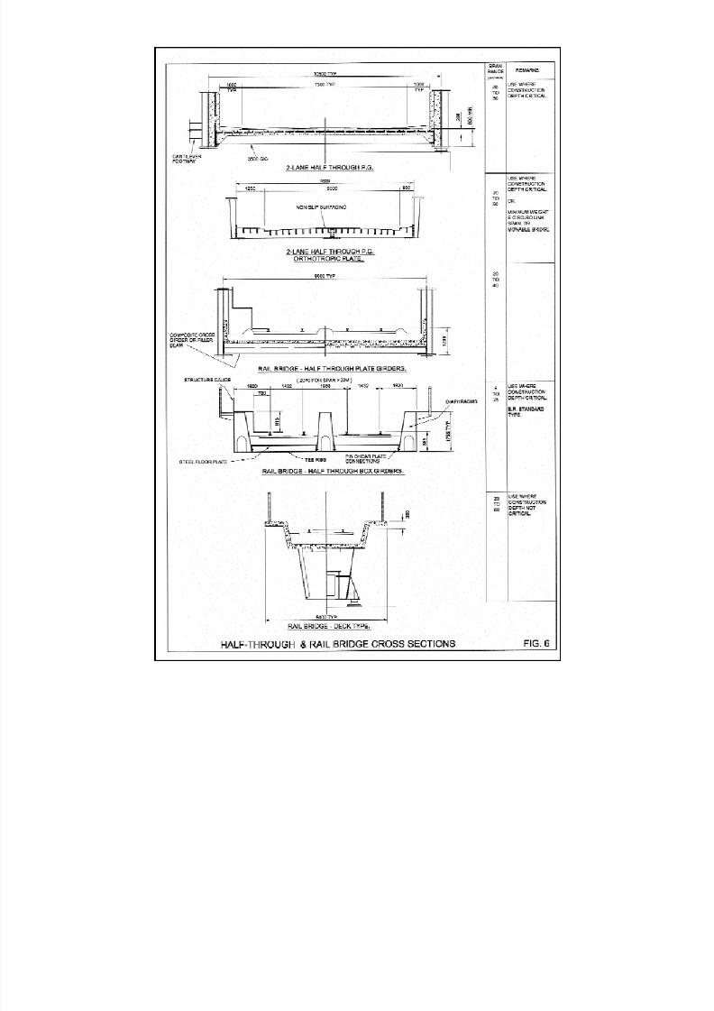
6 Half-Through and Rail Bridge Cross Sections . . . . . . . . . . . . . . . . . . 12
7 Available Plate Lengths . . . . . . . . . . . . . . . . . . . . . . . . . . . . . . . . . . 22
8 Economy of Flange/Web Thickness Changes . . . . . . . . . . . . . . . . . . 28
9 Typical Single Span Girder . . . . . . . . . . . . . . . . . . . . . . . . . . . . . . . . 29
10 Typical Bolted & Welded Splices. . . . . . . . . . . . . . . . . . . . . . . . . . . . 30
11 Plate Girder Assembly . . . . . . . . . . . . . . . . . . . . . . . . . . . . . . . . . . . 31
12 Detailing Do’s & Don’ts. . . . . . . . . . . . . . . . . . . . . . . . . . . . . . . . . . . 39
13 Orthotropic Plate Stiffeners. . . . . . . . . . . . . . . . . . . . . . . . . . . . . . . . 40
14 Weld Distortion and Correction. . . . . . . . . . . . . . . . . . . . . . . . . . . . . 41
15 Tonna Bridge Replacement . . . . . . . . . . . . . . . . . . . . . . . . . . . . . . . 62
16 A34 Newbury Bypass – Donnington Link . . . . . . . . . . . . . . . . . . . . . 66
17 Westgate Bridges . . . . . . . . . . . . . . . . . . . . . . . . . . . . . . . . . . . . . . 68
18 Churn Valley Viaduct . . . . . . . . . . . . . . . . . . . . . . . . . . . . . . . . . . . . 70
19 A500 Basford Hough, Bridge over Railway . . . . . . . . . . . . . . . . . . . . 72
20 Doncaster North Bridge . . . . . . . . . . . . . . . . . . . . . . . . . . . . . . . . . . 74
21 A69 Haltwhistle Bypass Railway Viaduct . . . . . . . . . . . . . . . . . . . . . . 76
22 River Exe Viaduct . . . . . . . . . . . . . . . . . . . . . . . . . . . . . . . . . . . . . . 78
23 Newark Dyke Rail Bridge Reconstruction . . . . . . . . . . . . . . . . . . . . . 81
Tables Title
1 Guide to Minimum Cambers in Universal Beams . . . . . . . . . . . . . . . . 13
2 Road Transport Length/Width Restrictions . . . . . . . . . . . . . . . . . . . . 13
3 Relative Efficiency and Limiting Thickness of Steel Grades . . . . . . . . . 18
4 Weathering Steel Corrosion Allowance to BD7/01
Related to 120 Year Design Life . . . . . . . . . . . . . . . . . . . . . . . . . . . . 21
5 Compression Outstand Limit to Flanges . . . . . . . . . . . . . . . . . . . . . . 23
8/7/2019 52512003 Steel Bridges
http://slidepdf.com/reader/full/52512003-steel-bridges 9/96
1.1 Introduction
Steel is usually the material best-suited to meet therequirements in the UK for highways and railway
bridges, footbridges and moving bridges. Steel
construction is, though, a peculiar part of civil
engineering construction as all of the planning and
preparation is done off site, most elements critical to
the bridge are made in a remote factory, and indeed
the work at site may last but a few days. Production of
the bridgeworks in a factory has many advantages in
terms of precision, quality, economy and safety but the
differences from other civil engineering activities need
to be understood if the potential of steel is to be
exploited by the designer. The objective of this
publication is to facilitate an understanding of those
aspects of fabrication and erection that influence the
quality and economics of steel bridgeworks so that the
designer is able to achieve an optimum solution for
his client.
Fabrication of the steelwork represents a significant
part of the overall cost of a bridge. Each fabrication
shop has a layout which has been developed with
equipment appropriate to the types and scale of
structures in which the company specialises. There is
not always a single preferred method for fabricating a
particular component or detail. Some details may suit
automated fabrication processes but may be less
appropriate for those companies which use more
traditional practices - good quality work can be
produced in highly automated shops, almost without
the use of fabrication drawings, and also by skilled
tradesmen in basic shops with modest equipment.
However, there are certain limitations for most of the
details and impractical arrangements to be avoided
which, if anticipated knowledgeably at the design
stage, will enable economical and easy fabrication.
Most of the advice given in this publication relates to
highway, railway and pedestrian bridges in the UK of short and medium span of conventional types. Steel is
eminently suitable for long span bridges, including
suspension and cable-stayed spans, and for
mechanical bridges which fall outside the scope of this
book, though much of the content is relevant to them.
Similarly the design of bridges for other countries, and
of bridgeworks for export, involves considerations
which are outside the scope of this book.
The production of a new bridge for its sponsor involves
a team of organisations and individuals working
together. Traditionally there was the Engineer and the
Contractor, but with new forms of procurement theseroles do not necessarily exist within a contract: so it is
convenient for the purpose of this book to use the
terms 'designer' and 'steelwork contractor' to identify
two of the key roles in building a steel bridge. However,
removal of the term 'Engineer' from the text has not
been possible since current British Standards,
including BS 5400: Part 6, retain it. The term 'designer'
is used to identify the organisation responsible for the
design of the permanent works, whether employed by
the client, main contractor or steelwork contractor, and
whose responsibilities include all the technical matters
involving design, decision-making and approval for the
implementation of the design during the contract. The
role of 'steelwork contractor' covers responsibility for
fabrication and erection (and certainly these are best
undertaken by one organisation even though it may
choose to subcontract part): it includes responsibility
for choosing fabrication methods, fabrication
drawings, material procurement, erection method,
construction engineering and temporary works design,
protective treatment and, when required and
appropriate, bearing supply.
The steelwork contractor and the designer for a steel
project must understand each other's roles and
responsibilities to obtain the best outcome
economically and technically. The designer should
have close contact with the steelwork contractor and
be able to discuss ideas with him where they have a
mutual bearing. Equally it is important that the
steelwork contractor is free to raise points with the
designer where the end product and the project
outcome for the client will be improved. This is made
easier when a design and construct contract is used,
as has been demonstrated on many successful bridge
projects over the last 20 years.
Design of bridges for the UK is currently carried out to
BS 5400, with Part 3 covering design of steel bridges,
Part 5 the design of composite bridges, and Part 6 the
workmanship of steel bridges. For highway bridgesreference has to be made to Departmental Standards
and for railway bridges to Railtrack Group Standards;
these standards are referred to in the text, as are many
of the associated British Standards. Through the life of
this edition it is certain that British Standards will be
replaced by Euronorms and Eurocodes, but in most
instances they will not invalidate the practical advice
and technical information provided by the book. It is
not clear how the implementation of the Eurocodes
may affect practices, for example, in the definition of
workmanship tolerances compatible with design
assumptions, but the codes cannot change theessential characteristics of working with steel.
1
CHAPTER 1
DESIGN CONCEPTION

8/7/2019 52512003 Steel Bridges
http://slidepdf.com/reader/full/52512003-steel-bridges 10/96
Sustainability is a crucial issue for today's construction
industry. Construction has to be socially and
environmentally responsible as well as economically
viable. Steel is a sustainable construction material to
use for bridgework and good design will enhance its
sustainability characteristics which are very evident in
the material itself, the manufacture of the structural
components, and the relatively straightforward andswift construction of most steel bridges today:
a) New steel plate and sections contain a significant
proportion of recycled material, and they are fully
recyclable at the end of the life of the structure.
b) Innovation and technological advances - in
fabrication, in equipment and infrastructure for
delivery, and in construction plant and techniques -
have enabled the move to more complete off-site
manufacture so that typical bridge members are
truly manufactured products, with all the
advantages that brings. These include higher
productivity, less waste, energy efficiency, better
working conditions, and a more easily controlled
process, with less adverse impact on the
environment.
c) Steel bridge construction is typically a brief and
highly organised activity in the overall construction
programme, utilising highly mobile equipment and a
small workforce of skilled people. Delivery can be
timed to minimise inconvenience; relatively little
space is required to operate; the steelwork is clean,
with no dust, little waste, and noise is not a major
problem. Erection schemes can be designed
readily to meet environmental constraints and
concerns. The speed of the erection process
means that any inconvenience or environmental
impact is reduced to a minimum period.
Sustainability in the bridge project is an issue for both
the steelwork contractor and the designer: it is another
important quality aspect which benefits from the
quality of the care and skill with which they fulfil their
respective roles.
Since the publication of the first edition of this book,
the regulatory environment for health and safety in
construction has been much enhanced and health andsafety considerations have become an integral part of
design as well as planning and carrying out
construction works - the Construction and Design
(Management) Regulations have been a major factor in
this development. Although this edition has not been
extended specifically to cover such considerations, its
underlying purpose is to improve the designer’s
understanding of steelwork and his competence in
using it for bridge construction. So, for example, the
designer must also consider issues such as designing
for the work to be done in the workshop rather than on
site, elastic instability of slender girders and access forsite tasks. Similarly the client, with professional advice,
has to satisfy himself that the chosen steelwork
contractor is competent to undertake the challenge of
his design. The establishment of the independent
Register of Qualified Steelwork Contractors (RQSC)
addresses this by including those steelwork
contractors who can demonstrate their relevant set of
commercial and technical qualifications to undertake
steel bridgeworks. The Register, which is described inChapter 9, categorises the competent firms by size
(turnover) and capability for different types of bridge: it
is open to any company which can meet the objective
criteria for competence assessed by independent
engineers of standing. The Highways Agency now
requires that only registered steelwork contractors are
engaged for UK highway bridgeworks.
1.2 Initial Conception
For new build highways or railways the requirements
for bridges are determined by the alignment, local
terrain and the obstacles which are to be crossed.Ideally the designer should be involved at an early
stage to optimise overall geometry for the bridge spans
and the interfaces with earthworks taking account of
the cost influences of sighting distances, skew,
curvature and construction depth. At the time of
construction of the early motorways from the 1950’s to
the 1980’s greenfield conditions allowed considerable
freedom of choice in alignments and methods of
construction. However, with the growing urbanisation
and traffic density in the UK and elsewhere from the
1980’s considerable restrictions arose in the provision
of new transport systems and the extension of existingsystems. Thus the number of requirements for bridges
across obstacles is increased and designers are often
constrained to adopt curved, tapered or skewed
structures with severe limitations on construction
depth. Moreover, the public objections to traffic
disruption mean that the methods and speed of
construction heavily influence bridge design now.
These trends have encouraged a move towards
prefabrication of elements favouring the use of
structural steel as the primary medium for bridge
spans, whilst capitalising on the merits of concrete and
other materials in substructures, for formwork and in
bridge deck slabs.
For replacement spans, or new bridges beneath
existing highways or rail tracks, the form of
construction will be dictated by the needs of a live
highway or railway in keeping disruption of traffic to an
absolute minimum. This favours prefabricated forms
of construction which can be erected rapidly during
possession, or which can be assembled adjacent to
the highway or rail track for speedy installation by
reliable sliding, rolling-in or wheeled transportation
methods. Steel is ideal as the main structural materialin these situations.
2
8/7/2019 52512003 Steel Bridges
http://slidepdf.com/reader/full/52512003-steel-bridges 11/96
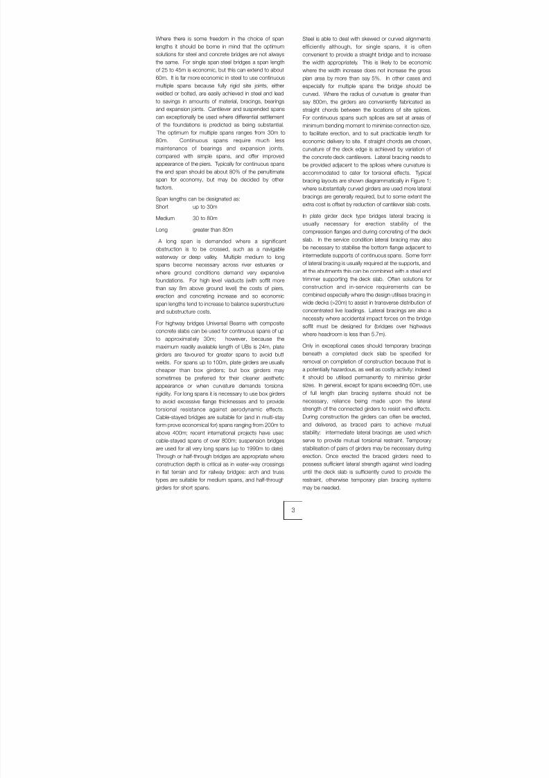
Where there is some freedom in the choice of span
lengths it should be borne in mind that the optimum
solutions for steel and concrete bridges are not always
the same. For single span steel bridges a span length
of 25 to 45m is economic, but this can extend to about
60m. It is far more economic in steel to use continuous
multiple spans because fully rigid site joints, either
welded or bolted, are easily achieved in steel and leadto savings in amounts of material, bracings, bearings
and expansion joints. Cantilever and suspended spans
can exceptionally be used where differential settlement
of the foundations is predicted as being substantial.
The optimum for multiple spans ranges from 30m to
80m. Continuous spans require much less
maintenance of bearings and expansion joints,
compared with simple spans, and offer improved
appearance of the piers. Typically for continuous spans
the end span should be about 80% of the penultimate
span for economy, but may be decided by other
factors.
Span lengths can be designated as:
Short up to 30m
Medium 30 to 80m
Long greater than 80m
A long span is demanded where a significant
obstruction is to be crossed, such as a navigable
waterway or deep valley. Multiple medium to long
spans become necessary across river estuaries or
where ground conditions demand very expensive
foundations. For high level viaducts (with soffit more
than say 8m above ground level) the costs of piers,erection and concreting increase and so economic
span lengths tend to increase to balance superstructure
and substructure costs.
For highway bridges Universal Beams with composite
concrete slabs can be used for continuous spans of up
to approximately 30m; however, because the
maximum readily available length of UBs is 24m, plate
girders are favoured for greater spans to avoid butt
welds. For spans up to 100m, plate girders are usually
cheaper than box girders; but box girders may
sometimes be preferred for their cleaner aesthetic
appearance or when curvature demands torsionalrigidity. For long spans it is necessary to use box girders
to avoid excessive flange thicknesses and to provide
torsional resistance against aerodynamic effects.
Cable-stayed bridges are suitable for (and in multi-stay
form prove economical for) spans ranging from 200m to
above 400m; recent international projects have used
cable-stayed spans of over 800m; suspension bridges
are used for all very long spans (up to 1990m to date).
Through or half-through bridges are appropriate where
construction depth is critical as in water-way crossings
in flat terrain and for railway bridges: arch and truss
types are suitable for medium spans, and half-throughgirders for short spans.
Steel is able to deal with skewed or curved alignments
efficiently although, for single spans, it is often
convenient to provide a straight bridge and to increase
the width appropriately. This is likely to be economic
where the width increase does not increase the gross
plan area by more than say 5%. In other cases and
especially for multiple spans the bridge should be
curved. Where the radius of curvature is greater thansay 800m, the girders are conveniently fabricated as
straight chords between the locations of site splices.
For continuous spans such splices are set at areas of
minimum bending moment to minimise connection size,
to facilitate erection, and to suit practicable length for
economic delivery to site. If straight chords are chosen,
curvature of the deck edge is achieved by variation of
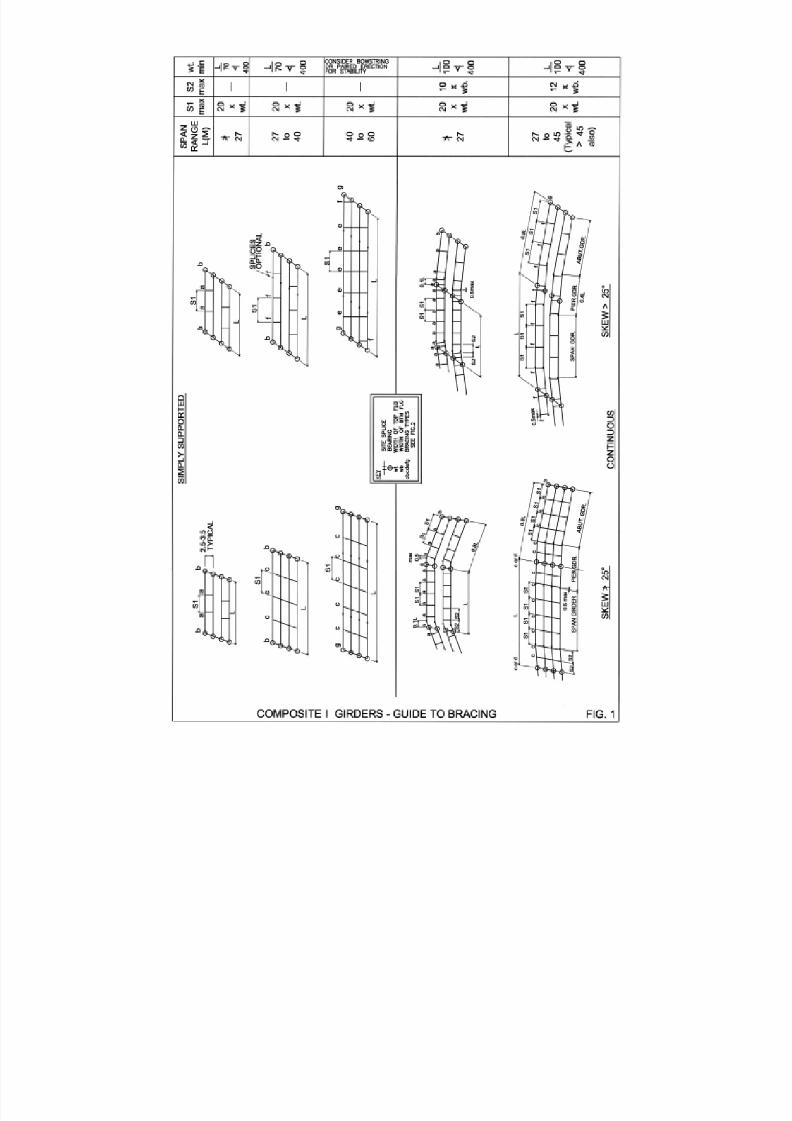
the concrete deck cantilevers. Lateral bracing needs to
be provided adjacent to the splices where curvature is
accommodated to cater for torsional effects. Typical
bracing layouts are shown diagrammatically in Figure 1;
where substantially curved girders are used more lateral
bracings are generally required, but to some extent the
extra cost is offset by reduction of cantilever slab costs.
In plate girder deck type bridges lateral bracing is
usually necessary for erection stability of the
compression flanges and during concreting of the deck
slab. In the service condition lateral bracing may also
be necessary to stabilise the bottom flange adjacent to
intermediate supports of continuous spans. Some form
of lateral bracing is usually required at the supports, and
at the abutments this can be combined with a steel end
trimmer supporting the deck slab. Often solutions for
construction and in-service requirements can becombined especially where the design utilises bracing in
wide decks (>20m) to assist in transverse distribution of
concentrated live loadings. Lateral bracings are also a
necessity where accidental impact forces on the bridge
soffit must be designed for (bridges over highways
where headroom is less than 5.7m).
Only in exceptional cases should temporary bracings
beneath a completed deck slab be specified for
removal on completion of construction because that is
a potentially hazardous, as well as costly activity: indeed
it should be utilised permanently to minimise girder
sizes. In general, except for spans exceeding 60m, useof full length plan bracing systems should not be
necessary, reliance being made upon the lateral
strength of the connected girders to resist wind effects.
During construction the girders can often be erected,
and delivered, as braced pairs to achieve mutual
stability: intermediate lateral bracings are used which
serve to provide mutual torsional restraint. Temporary
stabilisation of pairs of girders may be necessary during
erection. Once erected the braced girders need to
possess sufficient lateral strength against wind loading
until the deck slab is sufficiently cured to provide the
restraint, otherwise temporary plan bracing systemsmay be needed.
3
8/7/2019 52512003 Steel Bridges
http://slidepdf.com/reader/full/52512003-steel-bridges 12/96
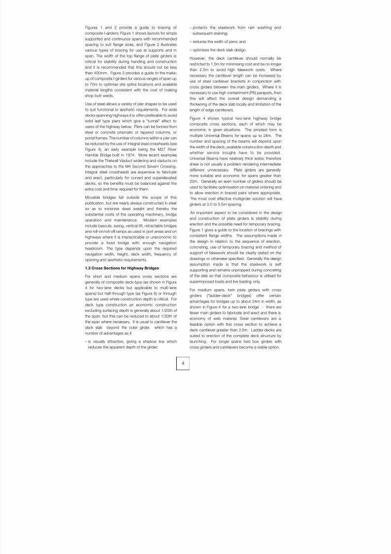
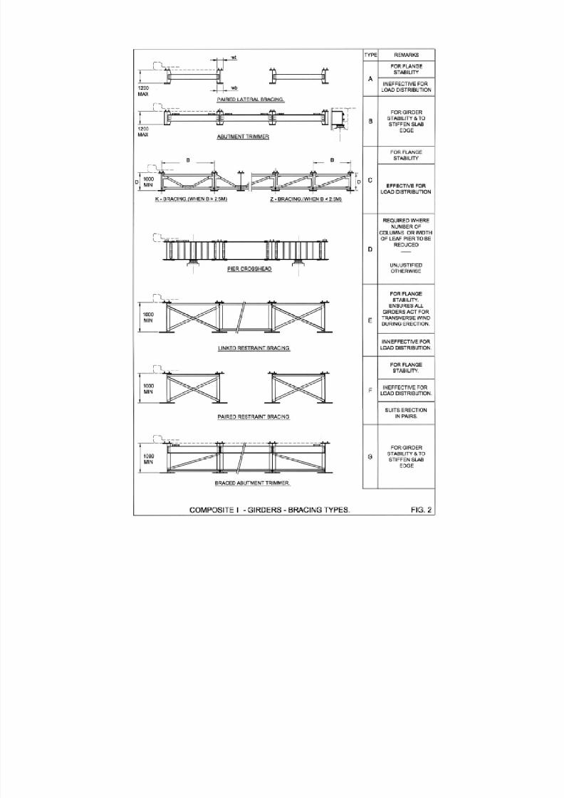
Figures 1 and 2 provide a guide to bracing of
composite I-girders: Figure 1 shows layouts for simply
supported and continuous spans with recommended
spacing to suit flange sizes, and Figure 2 illustrates
various types of bracing for use at supports and in
span. The width of the top flange of plate girders is
critical for stability during handling and construction
and it is recommended that this should not be lessthan 400mm. Figure 3 provides a guide to the make-
up of composite I-girders for various ranges of span up
to 70m to optimise site splice locations and available
material lengths consistent with the cost of making
shop butt welds.
Use of steel allows a variety of pier shapes to be used
to suit functional or aesthetic requirements. For wide
decks spanning highways it is often preferable to avoid
solid leaf type piers which give a "tunnel" effect to
users of the highway below. Piers can be formed from
steel or concrete prismatic or tapered columns, or
portal frames. The number of columns within a pier can
be reduced by the use of integral steel crossheads (see
Figure 4), an early example being the M27 River
Hamble Bridge built in 1974. More recent examples
include the Thelwall Viaduct widening and viaducts on
the approaches to the M4 Second Severn Crossing.
Integral steel crossheads are expensive to fabricate
and erect, particularly for curved and superelevated
decks, so the benefits must be balanced against the
extra cost and time required for them.
Movable bridges fall outside the scope of this
publication, but are nearly always constructed in steel
so as to minimise dead weight and thereby the
substantial costs of the operating machinery, bridge
operation and maintenance. Modern examples
include bascule, swing, vertical lift, retractable bridges
and roll-on/roll-off ramps as used in port areas and on
highways where it is impracticable or uneconomic to
provide a fixed bridge with enough navigation
headroom. The type depends upon the required
navigation width, height, deck width, frequency of
opening and aesthetic requirements.
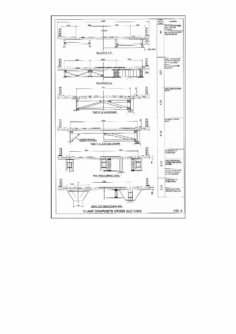
1.3 Cross Sections for Highway Bridges
For short and medium spans cross sections are
generally of composite deck-type (as shown in Figure
4 for two-lane decks but applicable to multi-lane
spans) but half-through type (as Figure 6) or through
type are used where construction depth is critical. For
deck type construction an economic construction
excluding surfacing depth is generally about 1/20th of
the span, but this can be reduced to about 1/30th of
the span where necessary. It is usual to cantilever the
deck slab beyond the outer girder, which has a
number of advantages as it
– is visually attractive, giving a shadow line whichreduces the apparent depth of the girder;
– protects the steelwork from rain washing and
subsequent staining;
– reduces the width of piers; and
– optimises the deck slab design.
However, the deck cantilever should normally be
restricted to 1.5m for minimising cost and be no longer
than 2.5m to avoid high falsework costs. Where
necessary the cantilever length can be increased by
use of steel cantilever brackets in conjunction with
cross girders between the main girders. Where it is
necessary to use high containment (P6) parapets, then
this will affect the overall design demanding a
thickening of the deck slab locally and limitation of the
length of edge cantilevers.
Figure 4 shows typical two-lane highway bridge
composite cross sections, each of which may be
economic in given situations. The simplest form is
multiple Universal Beams for spans up to 24m. Thenumber and spacing of the beams will depend upon
the width of the deck, available construction depth and
whether service troughs have to be provided.
Universal Beams have relatively thick webs; therefore
shear is not usually a problem rendering intermediate
stiffeners unnecessary. Plate girders are generally
more suitable and economic for spans greater than
20m. Generally an even number of girders should be
used to facilitate optimisation on material ordering and
to allow erection in braced pairs where appropriate.
The most cost effective multigirder solution will have
girders at 3.0 to 3.5m spacing.
An important aspect to be considered in the design
and construction of plate girders is stability during
erection and the possible need for temporary bracing.
Figure 1 gives a guide to the location of bracings with
consistent flange widths. The assumptions made in
the design in relation to the sequence of erection,
concreting, use of temporary bracing and method of
support of falsework should be clearly stated on the
drawings or otherwise specified. Generally the design
assumption made is that the steelwork is self
supporting and remains unpropped during concreting
of the slab so that composite behaviour is utilised for
superimposed loads and live loading only.
For medium spans, twin plate girders with cross
girders ("ladder-deck" bridges) offer certain
advantages for bridges up to about 24m in width, as
shown in Figure 4 for a two-lane bridge - there are
fewer main girders to fabricate and erect and there is
economy of web material. Steel cantilevers are a
feasible option with this cross section to achieve a
deck cantilever greater than 2.5m. Ladder-decks are
suited to erection of the complete deck structure by
launching. For longer spans twin box girders withcross girders and cantilevers become a viable option.
4
8/7/2019 52512003 Steel Bridges
http://slidepdf.com/reader/full/52512003-steel-bridges 13/96
8/7/2019 52512003 Steel Bridges
http://slidepdf.com/reader/full/52512003-steel-bridges 14/96

8/7/2019 52512003 Steel Bridges
http://slidepdf.com/reader/full/52512003-steel-bridges 15/96
8/7/2019 52512003 Steel Bridges
http://slidepdf.com/reader/full/52512003-steel-bridges 16/96

8/7/2019 52512003 Steel Bridges
http://slidepdf.com/reader/full/52512003-steel-bridges 17/96
Multiple box girders are suitable for medium spans
where appearance of the bridge soffit is very important
and the presence of bracings is deemed unacceptable
as for example in a prominent urban area where
pedestrians view the soffit. Open topped box girders
are used extensively in North America and there are
some examples in the UK, including the River Nene
Bridge at Northampton and the A43 Towcester Bridge. Temporary lateral and plan bracing systems are,
however, necessary to maintain stability during
construction. Closed boxes, which are more stable
during fabrication and erection, are also used, but
current health and safety regulations for confined
space working make work inside them very expensive.
For long spans where the weight of the deck becomes
dominant, it is more appropriate to use an all steel
orthotropic stiffened deck plate instead of a concrete
slab. For the primary members either single or twin
box girders are used. Such boxes and deck are
assembled from separate stiffened plate elements at a
construction yard convenient for the site, and
transported to site for erection as large units. Such a
procedure was used for example on the Severn
Suspension Bridge and Humber Bridge.
To reduce site assembly and erection costs, where
there is access from the sea, complete spans may be
assembled in a shipyard or port and taken by barge
transport for erection in place. Examples are the Foyle
Bridge built in Belfast for erection in Londonderry, and
Scalpay Bridge, which was taken complete to the
Outer Hebrides.
1.4 Cross Sections for Railway Bridges
For replacements of existing spans cross sections are
influenced by construction depth limitations because
existing decks often have substandard ballasted track
depth, or the rails are mounted directly via longitudinal
timbers. Modern standards typically demand 300mm
ballast depth beneath sleepers giving a total track
depth of approximately 690mm below rail level,
allowing 25mm for floor waterproofing. Half through
construction is most usual for deck replacements and
for new bridges beneath existing railways to avoid
track lifting which may be impracticable or very costly.
Spans are generally simply supported to permit
piecemeal construction under traffic conditions.
Half through cross sections should, where possible,
avoid centre girders which project in excess of 100mm
above rail level within the "six foot" space between
tracks. It is important to check that any part of the
structure or furniture does not infringe the structure
gauge or lateral clearance for walkways taking account
of any curvature and cant, allowing for centre-throw
and end-throw of rail vehicles. Modern standardsrecommend the provision of a robust kerb extending at
least 300mm above rail level to contain derailed
vehicles, although many existing bridges do not
possess this.
For short spans up to about 17m the girders need not
project more than 110mm above rail level and each
track can be supported by a separate deck, which
facilitates piecemeal replacements and site delivery.
The Railtrack Standard ‘ZED’ type bridge uses shallow
plate girders of zed configuration, so that maintenance
space is available between adjacent decks, with cross
girders and enveloping deck slab. A variant is the
Cass Hayward U-deck which integrates the main
girders with a deck of either all steel or composite form
to achieve a single piece for fabrication and erection.
Where practicable a robust kerb can be incorporated
in these designs by deepening the outermost girders
and locating them within the platform gauge.
For spans up to about 40m girders can be located so
that they fit within the platform gauge extending not
more than 915mm above rail level. The Railtrack
standard box girder type bridge which covers a span
range from 12m to 39m uses trapezoidal box girders
with a transverse ribbed steel deck spanning between
notionally pin-jointed shear plate connections: the box
girders are stabilised by linear rocker bearings centred
beneath the inner web. This design is particularly
suited to piecemeal crane erection during track
possession. For some recent projects, plate girder
alternatives have proved economic where the site has
sufficient width to accommodate them.
For spans exceeding about 40m the girder depth
dictates that they are located outside the structure
gauge, so increasing the span of the deck between the
main girders. Half through plate girders or box girders
can be used, plate girders often being modelled on the
former type ‘E’ bridge with rolled section cross girders
spanning between rigid shear plate bolted connections
in line with external stiffeners to give ‘U’ frame stability.
The deck can be either in situ concrete partially
encasing the cross girders or of stiffened steel plate
construction, depending on the envisaged erection
method. For spans in excess of about 60m, through
or half through trusses or bowstring girders become
appropriate. Examples are bridge 70A at Stockportacross the M63 and M64 motorways having a truss
span of 120m, and the Newark Dyke bridge
reconstruction with a braced arch span of 77m.
For new build railways it is often possible to adopt a
deck type solution with the benefit of an efficient cross
section of a concrete slab acting compositely with
plate or box girders. Here the advice given in 1.3 for
deck type highway bridges would generally apply.
Where train speeds in excess of 125mph are
envisaged special design criteria need to be applied
concerning limits on vibration and deformation which
may influence, in particular, the depth of constructionand form of bridge deck.
9
8/7/2019 52512003 Steel Bridges
http://slidepdf.com/reader/full/52512003-steel-bridges 18/96
8/7/2019 52512003 Steel Bridges
http://slidepdf.com/reader/full/52512003-steel-bridges 19/96
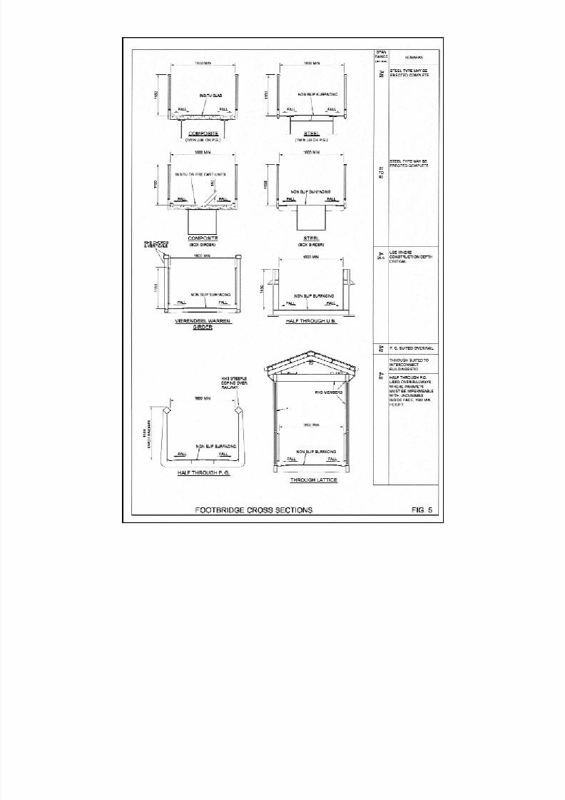
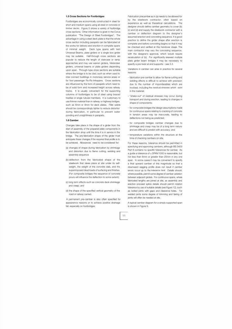
1.5 Cross Sections for Footbridges
Footbridges are economically constructed in steel for
short and medium spans using all steel or concrete or
timber decks. Figure 5 shows a variety of footbridge
cross sections. Other information is given in the Corus
publication "The Design of Steel Footbridges". The
advantage in using a steel deck plate is that the whole
cross section including parapets can be fabricated at
the works for delivery and erection in complete spans
of minimal weight. Deck type spans with twin
Universal Beams, plate girders or a single box girder
may be suitable. Half-through cross sections are
popular to reduce the length of staircase or ramp
approaches and may use warren girders, Vierendeel
girders, universal beams or plate girders depending
upon span. Through-type cross sections are suitable
where the bridge is to be clad, such as when used to
inter-connect buildings in motorway service areas or
for foot passenger Ro-Ro linkspans. Cross sectionsare influenced by the form of parapets which need to
be of solid form and increased height across railway
tracks. It is usually convenient for the supporting
columns of footbridges to be of steel using braced
trestles or single tubular members. It is customary to
use thinner material than in railway or highway bridges,
such as 6mm or 8mm for deck plates. Fillet welds
should be correspondingly lighter to reduce distortion
during fabrication, in particular to prevent water
ponding and unsightliness in parapets.
1.6 Camber
Changes take place in the shape of a girder from the
start of assembly of the prepared plate components in
the fabrication shop until the time it is in service in the
bridge. The pre-fabrication shape of the girder must
anticipate these changes if the required final profile is to
be achieved. Allowances need to be considered for:
(a) changes of shape during fabrication by shrinkage
and distortion due to flame cutting, welding and
assembly sequence;
(b) deflection from the fabricated shape of the
steelwork that takes place at site under its self-
weight, the weight of the concrete slab, and the
superimposed dead loads of surfacing and finishes.
(For composite bridges the sequence of concrete
pours will influence the deflection to some extent);
(c) long term effects such as concrete deck shrinkage
and creep; and
(d) the shape of the specified vertical geometry of the
road or railway carried.
A permanent pre-camber is also often specified for
appearance reasons or to achieve positive drainagefall, especially on footbridges.
Fabrication precamber as in (a) needs to be allowed for
by the steelwork contractor, often based on
experience as well as theoretical calculations. The
designer should define camber geometry to cover (b)
(c) and (d) and supply the steelwork contractor with a
camber or deflection diagram to the designer's
assumed erection and concreting sequence. It is good
practice to define the girder shape after erection iscomplete and before concreting begins so that it may
be checked and verified at this handover stage. The
main contractor may vary the concreting sequence,
with the designer’s approval, which would require
recalculation of (b). For significantly skewed multiple
plate girder beam bridges it may be necessary to
specify a pre-twist at end supports – see 5.3.
Variations in camber can arise in practice for several
reasons:
– fabrication pre-camber to allow for flame cutting and
welding effects is difficult to achieve with precisiondue to the number of imponderables which are
involved, including the residual stresses which exist
in the material;
– "shake-out" of residual stresses may occur during
transport and during erection, leading to changes in
shape of components;
– for composite bridges the design assumptions made
for continuous spans relating to cracking of concrete
in tension areas may be inaccurate, leading to
deflections not being as predicted;
– for composite bridges camber changes due to
shrinkage and creep may be of a long term nature
and are difficult to predict with accuracy; and
– temperature variations within the structure at the
time of checking cambers on site.
For these reasons, tolerance should be permitted in
specifying and approving cambers, although BS 5400
Part 6 contains no specific tolerances for camber. As
a guide a tolerance of ± SPAN/1000 is reasonable, but
not less than 6mm or greater than 25mm in any one
span. In some cases it may be convenient to specify
a final upward camber of this magnitude so that a
downward sagging profile does not result if camber
errors occur up to the tolerance limit. Details should,
where possible, permit some degree of camber variation
between adjacent girders. For continuous spans, where
fabricated lengths are joined at site, as assembly and
erection proceed splice details should permit rotation
tolerance by use of suitable details (see Figure 12), such
as bolted joints with gaps and clearance holes. For
welded joints some degree of trimming and fairing of
joints will often be needed at site.
A typical camber diagram for a simply supported spanis shown in Figure 9.
11
8/7/2019 52512003 Steel Bridges
http://slidepdf.com/reader/full/52512003-steel-bridges 20/96

8/7/2019 52512003 Steel Bridges
http://slidepdf.com/reader/full/52512003-steel-bridges 21/96
Universal Beams can be cambered at the steel mill.
The operation is performed by bending the beams cold
to approximate a circular curve, but the beam may lose
small amounts of this camber due to release of
stresses put into the beam during the cambering
operation. Alternatively, where only small pre-cambers
are specified sufficient to counteract deflection (say
SPAN/1000 or 25mm for a 25m long Universal Beam)
then cambering by the steelwork contractor or other
specialist will need to be carried out. For very short
spans where appearance is not critical the designer
should consider whether any cambering is justified.
As a guide only, Table 1 gives the minimum cambers in
mm which are likely to remain permanent after
cambering for beams cambered at the steel mill.
Greater accuracy can be achieved by cambering in a
specialist rolling process, in which case cambering
tolerances are ± 3mm or + 5 – 0mm on mid ordinate
height, with no minimum camber as such.
1.7 Dimensional Limitations
For road transport of fabricated items within the UK the
restrictions in Table 2 apply.
Maximum height depends upon vehicle height and
shape of the load but generally items up to 3.0m high
can be transported. For rail transport advice must be
sought, but generally items up to 3.0m high, 2.9m
wide and 30.0m long can be carried by arrangement:
transport of steelwork by rail is currently extremely rare.
These restrictions and the requirements for erection
have a considerable effect upon the member sizes andlocation of site splices. The Figures are for guidance
only, eg 45m plate girders have been fabricated and
transported to site using a transporter with rear
steerable bogies. The steelwork contractor should be
allowed flexibility in fabricating in longer lengths
provided he can obtain the necessary permission to
transport such loads. Constraints at site or on the
route to site may restrict delivery dimensions or weight
so some flexibility to allow additional site splices may
be required.
Except for very large projects it is usually uneconomic
for large members (such as box girders) to be site
assembled from individual elements. Generally, the
longest possible members should be fabricated to
achieve the minimum number of site joints. Erection
costs are considerably influenced by unit weight so
crane sizes should be optimised wherever possible:
the crane size is determined by piece weight and the
radius for lifting which is dictated by the site layout. A
general guide is a maximum unit weight of 50 tonnes,
although with modern cranes larger lifts can be
achieved. In general site splices and girder lengthsshould be chosen to facilitate erection and the
appropriate erection method for the particular site.
When galvanizing is specified for corrosion protection
particular care must be adopted in the design and
detailing of the steelwork. Means of access and
drainage of the molten zinc and venting of the gases
from internal compartments is essential for each
assembly. During the galvanizing process (immersion
at about 450oC for approximately five minutes) stress
relief can sometimes cause distortion of light gauge
steelwork. The stresses can arise from welding,
cutting or cold working. As far as possible, eachassembly should be symmetrical and the welding
stresses balanced. Plate and box girders will tend to
13
TABLE 1. Guide to minimum cambers in Universal Beams
Beam Depth Beam Length (metres)(mm)
26 24 23 21 20 18 17 15 14 12 11 9
914 95 - 75 - 57 - 38 32 25 19 - -
834 100 - 83 - 63 - 44 38 32 25 - -
762 115 - 89 - 70 - 50 38 32 25 - -
686 127 - 101 - 75 - 50 44 38 32 - -
610 127 - 115 - 82 - 63 50 38 32 - -
533 - 127 - 114 - 82 - 57 44 38 25 20
TABLE 2. Road Transport length/width restrictions
Method of Transport Max Width Max Rigid Length Max Laden Weight Max Axle Weight
(metres) (metres) (tonnes) (tonnes)
Free movement 2.9 18.6 38 10.5
Police to be informed 5.0 27.4 150 16.5
– escort required
Special movement order More than 5.0 More than 27.4
(at least 8 weeks notice)
8/7/2019 52512003 Steel Bridges
http://slidepdf.com/reader/full/52512003-steel-bridges 22/96
twist longitudinally due to the release of welding stress:
this is rarely an issue in assembly of plate girder
bridges but it does need consideration on box girder
bridges.
Consideration should also be given to factors (such as
detailing, material grade, locked-in stresses, good
fabrication practice) that will overcome the minimal risk
of cracking arising from the galvanizing process (liquid
metal assisted cracking or embrittlement). Advice is
available from galvanizing companies and from the
Galvanizers Association on these issues.
The maximum size and weight of assemblies that can
be galvanized depends upon the size of the bath and
craneage available. The largest baths, in 2001, are up
to 21m long by 1.5 to 2.0m wide by 2.7 to 3.5m deep.
By ‘double dipping’ (immersing part of the structure
and then reversing it for length and depth) larger sizes
can be galvanized subject to limitations on craneage
capacity.
1.8 Erection
Prior to the 1970's the erection of small and medium
span bridges required the steelwork contractor to
exercise ingenuity and expertise to devise schemes
using cranes of fairly limited capacity - a 50t derrick
crane mounted on travelling bogies was the largest
available. Extensive temporary works were common
with steel trestles in span to support short members
for splicing, or rolling in, cantilevering or launching
schemes; and, on occasion using floating craft for
cranes or girder movements. The steelwork contractor
had a significant amount of construction engineering todo which, for launching and cantilevering schemes,
involved analysis and modification of the permanent
works design to suit. These schemes required much
more activity at site to prepare and carry out, and
would take weeks rather than days.
With the advent of larger, and yet larger, capacity
mobile cranes from the 1970’s and the ability to deliver
longer components via the motorway system, erection
of many major bridges could be carried out more
rapidly and economically without resort to temporary
supports. The introduction of composite construction
in continuous multiple spans favoured delivery anderection in longer lengths too. These developments
led to simpler quicker erection for many bridges but
significant stresses could arise during construction,
and elastic instability of steel members during
construction became much more of an issue. This,
together with modern safety legislation, means the
designer has to anticipate the erection scheme and
completion of deck slab construction in his design of
the bridge. The production of method statements,
safety plans and risk assessments is required of the
designer as well as the steelwork contractor; and
today the checking of steelwork strength and stabilityat all stages of erection, as well as of any temporary
works, is required to be rigorous and documented. The
contractor is responsible for the erection scheme as
well as its implementation: the designer has to
anticipate it properly.
Erection of short and medium span steel bridges is
most commonly carried out using road mobile or
tracked crawler cranes. Road mobile cranes require
firm ground conditions to get on to site and at the workpositions where they use outriggers to develop full
capacity. The largest cranes, and with derrick
counterweight installed, have the capacity to lift more
than 50 tonnes at 50m radius, or 100 tonnes at 28m
radius: these cranes are suitable for erection of most
small and many medium span bridge girders where a
unit weight not exceeding 50 tonnes is involved. In
poor but level ground conditions crawler cranes have
flexibility in being able to travel with the load and,
typically, can lift up to 15 tonnes at 50m radius
travelling. Hire costs and crane assembly periods for
mobile cranes increase substantially for the larger
cranes, which may be demanded for example where ‘I’
girders are lifted in pairs, but it is advantageous if
erection can be performed using the minimum number
of lifts and crane positions. Crawler cranes are not
economic for short hire periods, but are more cost
effective than road mobile cranes for long periods.
Ground supported temporary works are avoided
wherever possible, and personnel access is assisted
by use of mobile access platforms or cherry pickers.
For heavy lifts, cranes may be used in tandem, subject
to more severe lifting conditions, which can
significantly increase the erection costs. Mobile cranes
are usually hired by the steelwork contractorspecifically for the erection, so it is most economic if all
the steelwork within a bridge can be erected in one
continuous operation. Girders are generally lifted on
their centre of gravity using double slings connected to
temporary lifting lugs welded to the top flange. Sling
lengths are usually selected commensurate with
stability of the girder, whilst being lifted, so as to limit
the crane jib length needed and maximise on the crane
capacity.
For single spans, up to say 60m in length, any splices
whether bolted or welded would usually be made with
the girders aligned on temporary stillages at ground
level, before each girder is lifted complete. For
continuous spans, then ‘span’ and ‘pier’ girders would
be spliced similarly at ground level with erection
proceeding span by span and oversailing each pier to
avoid the need for any ground supported temporary
works. For plate girders erected singly of length
greater than about 40m then stability may demand use
of bowstrings or other temporary works to reduce the
effective flange length against buckling once the crane
is released. These erection methods are economic
and of little hindrance to other site operations for they
allow construction to advance rapidly without need forsubstantial ground supported temporary works.
14
8/7/2019 52512003 Steel Bridges
http://slidepdf.com/reader/full/52512003-steel-bridges 23/96
Erection by mobile cranes is generally the most
economic method provided access and space is
available for such cranes and for delivery of steelwork.
Where temporary supports are required standard ‘L’
trestling is often used with foundations using timber
sleepers or concrete, depending on ground
conditions. For long span bridges significant
temporary works will usually be necessary includingthe site pre-assembly of main members from separate
flange and web elements. If welded splices need to be
carried out in the final position rather than at ground
level some form of temporary works and welding
shelters with access for inspection and testing are
necessary – that is rather more provision than for
bolted connections.
Where erection has to be carried out during a limited
period such as in a railway possession or road closure
then lifting of complete bridge spans is preferable,
even though this increases the size or number of
cranes. Rail mounted cranes were much used in thepast for rail bridge erection, but have limited capacity;
they may be appropriate where no access is available
for road mobile cranes, however they are of limited
availabil ity. Where crane access is not feasible or
overly costly, such as for a waterway crossing, then
other erection methods including launching or rolling-in
may be called for: such schemes are less common
today but, in the hands of competent steelwork
contractors, are powerful ways of overcoming difficult
obstacles or logistical constraints.
Launching is most suitable for new build highway or
railway multiple continuous span bridges with constantheight girders or trusses. Where possible the
steelwork is assembled full length off one end of the
bridge and launched forward on rollers or slide units
mounted on tops of the permanent piers. A tapered
launching nose is used to minimise stressing of the
girders and remove the cantilever deflection of the
leading end as it approaches each support.
Propulsion may be by pulling with winches or strand
jacks, or by incremental jacking, followed by jacking
down on to the permanent bearings. Generally the
steelwork alone is launched, followed by deck slab
concreting, but launching of concreted spans can beadvantageous. An important design check is the
stability of the girder web or truss bottom chord above
the roller or slide units; the camber shape of the girders
to be taken into account; and the interface of the
girders with the temporary works must suit the sliding
or rolling action.
Lateral sliding in, rolling in or transporter units are used
for bridge replacements. The whole structure is
normally constructed and completed on temporary
supports alongside the bridge before it is moved
transversely and then jacked down onto its permanent
bearings. Railway bridges have for many years beenrolled in using 76mm (3") diameter steel balls running
on bullhead rails laid flat and surmounted by rolling
carriages beneath the steelwork: with the advent of
polytetrafluoroethylene (PTFE) and other low friction
materials sliding in is increasingly favoured in that
heavier loads can be carried. Propulsion is generally
by strand jacks or incremental jacking, followed by
jacking down onto permanent bearings. A
combination of longitudinal launching and lateralsliding may be appropriate.
The large crane is not the universal solution: modern
bridges of modest scale can still present very real
challenges to the ingenuity of the steelwork contractor
and the skill of the designer. For example, the Newark
Dyke rail bridge, which required complete replacement
in a three day closure of the East Coast main line at a
site of very restricted access, was effected by firstly
launching in turn the two braced arch girders across
the river, traversing them to receive cross girders and
deck concrete before the possession; then the lateral
slide in of the complete bridge including tracks duringthe three days which included sliding out the existing
structures for removal by pontoon.
The erection of steel bridges requires detailed
consideration by the designer, for it has to be safe and
practicable, and significant construction engineering
on the part of the steelwork contractor who will
develop and implement the scheme which is actually
used. It should be noted that fabrication and erection
may be carried out by different steelwork contractors,
but it is generally desirable that one steelwork
contractor is responsible for both. Site applied
protective treatment is generally carried out aftererection, and after deck concreting in the case of
composite bridges; this work is usually sub-let by the
steelwork contractor.
1.9 Repairs and Upgrading
The enormous increase of highway traffic since the
1980’s and the influence of heavier commercial
vehicles has led to revised bridge loading standards so
that many modern bridges are now regarded as sub-
standard. Major bridges strengthened since the early
1990’s include the Avonmouth, Severn, Wye, Forth,
Tay, Friarton and Tamar bridges, as well as smallerbridges of all types. Although railway loadings have
not significantly changed, many rail bridges are well
over 100 years old and are becoming life expired. The
planned introduction of higher train speeds above
125mph has led to new design criteria against
excessive vibration to maintain passenger comfort
levels and ballast stability, and consequently some
bridges require additional stiffness. All in all a
significant volume of steel bridgework now involves
repairs and upgrading.
Steel is particularly suitable for strengthening by added
material or duplicate members using bolted or sitewelding where appropriate. In some cases such as the
15

8/7/2019 52512003 Steel Bridges
http://slidepdf.com/reader/full/52512003-steel-bridges 24/96
M6 Thelwall Viaduct a composite riveted plate girder
structure strengthening was achieved by bolting on of
additional material and replacement of the existing
deck using stronger concrete and additional shear
connection. In other cases strengthening has
consisted merely of replacement of bearings and minor
works. Some bridges originally designed non
compositely have been made composite by
replacement of rivets by shear connectors.
Repairs to existing bridges have also been increasingly
required due to accidental collision of vehicles with
bridge soffits. Damage to steel members has generally
been found to be fairly local without fracture or risk of
overall collapse, due to the ductile properties of steel.
Depending upon the severity of damage several girder
bridges have, since 1999, been repaired by heat
straightening processes, as an alternative to costly
girder replacement: techniques as used in the USA
have been developed by UK steelwork contractors for
this work.
Designers and steelwork contractors undertaking
repair and strengthening works can face challenges
and hazards not met in new works; these can include
understanding the structure and how it works,
technical issues such as those presented by welding
to older materials; and safety hazards with access,
confined space working and the presence of
potentially toxic lead-based paints and cadmium
plating. Even the smallest of such projects should be
undertaken only by engineers and organisations with
the relevant knowledge and expertise.
16

8/7/2019 52512003 Steel Bridges
http://slidepdf.com/reader/full/52512003-steel-bridges 25/96
2.1 Introduction
The performance requirements for materials for steelbridges are contained in BS 5400: Part 3 (Design)
which requires the minimum UTS to be not less than
1.2 x the nominal yield stress, a ductility corresponding
to a minimum elongation of 15% and a notch
toughness to avoid brittle fracture. It is important to
remember that the ductility is an important property of
steel which allows it to be fabricated and shaped by
normal workshop practices. The requirements are met
using the appropriate strength grade and impact
qualities given in material standards BS 7668, BS EN
10025, BS EN 10113, BS EN 10137, BS EN 10155
and BS EN 10210 and are specified by the designer.
Grade S355 is the most common grade used in UK
bridges. Strength grades higher than S460 are not
covered by the design rules. BS 5400: Part 6
(Materials and Workmanship) contains detailed
requirements for materials including laminar defect
limits in critical areas, thickness tolerance, and
performance requirements for steels to standards
other than those above. The steel is required to be
supplied with a manufacturer’s certificate and to have
details of ladle analysis provided, so that the steelwork
contractor can check the details for welding
procedures.
2.2 Brittle Fracture and Notch Toughness
Requirements
The possibility of brittle fracture in steel structures is
not confined to bridges for it has to be considered
wherever stressed elements are used at low
temperatures, especially in thick material where
stresses are tensile, there are stress raising details and
the loading is applied rapidly. Steel having adequate
notch toughness properties at the design minimum
temperature should be specified so that when stressed
in the presence of a stress raising detail the steel will
have a tendency to strain rather than fracture in a brittle
manner. In fact, structural steelwork has a good
history of very few brittle fracture failures. There are a
number of contributory factors which help to prevent
brittle fracture from occurring, eg the risk of brittle
fracture is highest when the first high tensile stress
coincides with a very low temperature – where the first
high tensile stress occurs at a higher temperature, then
some element of "proofing" takes place. The first UK
limitation of notch toughness for steel in welded
tension areas of steel bridges was introduced in BS
153 in the mid 1960’s.
The standard Impact Test prescribed in EN 10045-1provides a measure of the notch toughness of a steel.
The test specimen is usually of square section 10 x
10mm and 60mm long with a notch across the centre
of one side: it is supported horizontally at each end in
the test machine and hit on the face behind the notch
by a pendulum hammer with a long sharp striking
edge. A pointer moved by the pendulum over a scale
indicates the energy used in breaking the specimen,
which is expressed as the Charpy energy in Joules at
the temperature of testing. The resistance of a steel
reduces with temperature so the test is usually carried
out at room temperature, and a range of low
temperatures to suit the specified requirement, say,
0oC, -10oC, -15oC, -20oC.
In BS 5400: Part 3: 2000 the required impact quality is
derived from an equation relating the maximum
permitted thickness of a steel part to:
- steel grade,
- design minimum temperature (see BS 5400: Part 2),
- construction detail,
- stress level, whether tension or compression, and
- rate of loading.
A key part of the equation is a k-factor which classifies
steel parts for fracture purposes.
For convenience table 3C in BS 5400: Part 3: 2000
gives maximum thickness limits for steels for k=1
which covers many situations where the design
stresses exceed 0.5sy and are tensile. For typical UK
minimum design temperatures the limiting thicknesses
are shown in Table 3, which takes account of nominal
yield strength variations with thickness.
Whilst stress relieving is generally allowed by the
standards, it is normally impractical for bridges due to
their large scale.
2.3 Internal Discontinuities in Rolled Steel
Products
Internal discontinuities are imperfections lying within the
thickness of the steel product. These may be planar or
laminar imperfections, or inclusion bands or clusters.
Typically such laminar imperfections run parallel to the
surface of a rolled steel product. They can very
occasionally originate from two main sources in the
ingot or slab from which the plate or section is rolled:
(a) entrapped non-metallic matter, such as steelmaking
slag, refractories or other foreign bodies (NB: Such
material may not necessarily form a ‘lamination’, if the
body fragments into smaller pieces on rolling, they may
appear as discrete or clusters of ‘inclusions’.
17
CHAPTER 2
STEEL QUALITIES
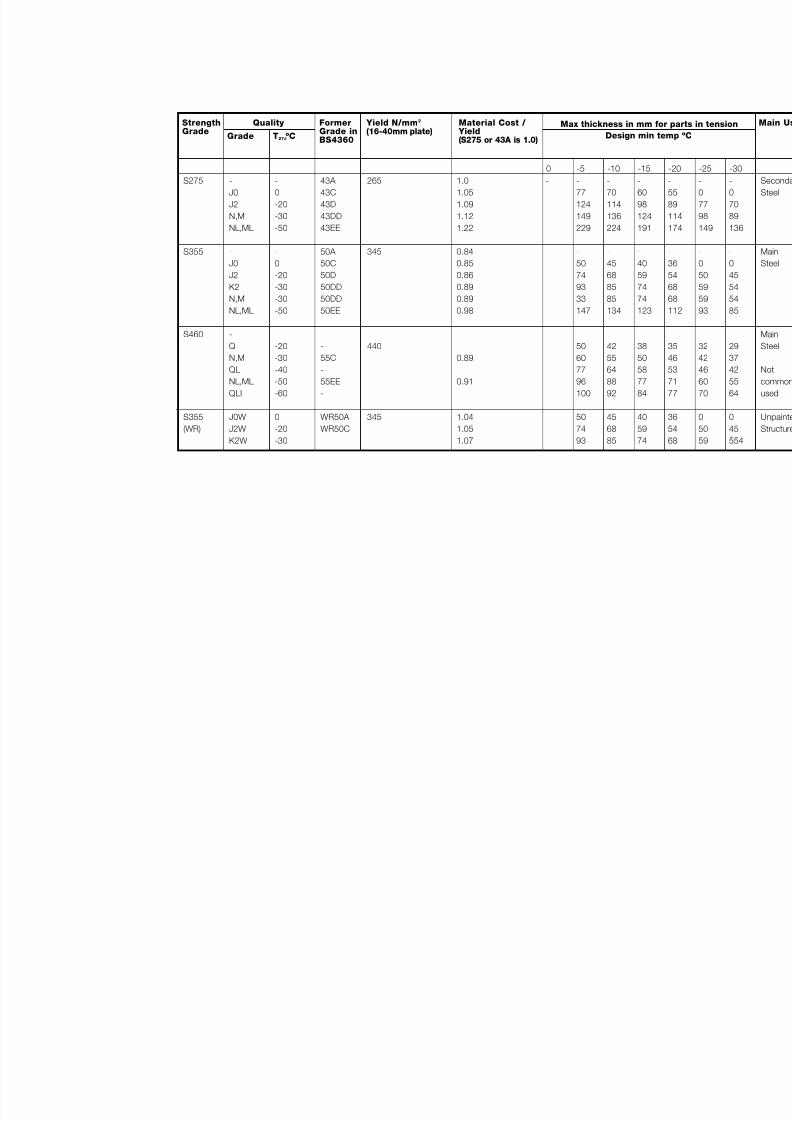
8/7/2019 52512003 Steel Bridges
http://slidepdf.com/reader/full/52512003-steel-bridges 26/96
S275
S355
S460
S355
(WR)
-
J0
J2
N,M
NL,ML
-
J0
J2K2
N,M
NL,ML
-
Q
N,M
QL
NL,ML
QLI
J0W
J2W
K2W
-
0
-20
-30
-50
-
0
-20-30
-30
-50
-20
-30
-40
-50
-60
0
-20
-30
43A
43C
43D
43DD
43EE
50A
50C
50D50DD
50DD
50EE
-
55C
-
55EE
-
WR50A
WR50C
- -
77
124
149
229
-
50
7493
33
147
50
60
77
96
100
50
74
93
-
70
114
136
224
-
45
6885
85
134
42
55
64
88
92
45
68
85
-
60
98
124
191
-
40
5974
74
123
38
50
58
77
84
40
59
74
-
55
89
11
17
-
36
5468
68
11
35
46
53
71
77
36
54
68
0 -5 -10 -15 -2
Max thickness in mm for p
Design min temp
265
345
440
345
1.0
1.05
1.09
1.12
1.22
0.84
0.85
0.860.89
0.89
0.98
0.89
0.91
1.04
1.05
1.07
StrengthGrade
FormerGrade in
BS4360
Yield N/mm2
(16-40mm plate)Material Cost / Yield
(S275 or 43A is 1.0)Grade
Quality
T27J ºC
8/7/2019 52512003 Steel Bridges
http://slidepdf.com/reader/full/52512003-steel-bridges 27/96
The distinction between a lamination and an inclusion
is purely arbitrary);
(b) a pipe
or from non-uniform distribution of alloying elements,
impurities or phases.
When an ingot solidifies it may contain shrinkage
cavities known as pipes. Providing they are notexposed to the atmosphere during reheating for
subsequent rolling, pipe cavities generally weld up
during the rolling process to give sound material. If a
pipe is exposed, say by trimming off the head of the
ingot, then its surface will oxidise during subsequent
reheating and this will prevent the cavity from welding
up. The resulting ‘lamination’, consisting largely of iron
oxide, is then a plane of weakness. Ingots are very
rarely used now and almost all steel produced in
Europe today is by the continuous casting process,
which eliminates this source of discontinuity.
Where a ‘lamination’ is wholly within the body of a plate
or section and is not excessively large it will not impede
the load-bearing capacity for stresses which are wholly
parallel to the main axes of the member. However,
‘laminations’ can cause problems if they are at or in
close proximity to a welded joint: thus a ‘lamination’ will
be a plane of weakness at a cruciform joint where it is
subjected to stresses through the thickness of the
plate or section. A related phenomenon is lamellar
tearing, which may occasionally occur at joints in
thicker sections subject to through-the-thickness
stresses under conditions of restraint during welding.
This results from a distribution of micro-inclusions,which link up under high through-thickness stresses
resulting in a distinctive stepped internal crack. It is
generally less common with modern steel-making
practice which produces lower average sulphur
contents than was the case up to the 1970’s. In
practice it is unlikely that failure will occur in service,
but full penetration welded cruciform joints should
generally be avoided because the heat inputs from
multi-run welding and back gouging processes can
cause a significant strain within the plate thickness,
resulting in a tearing kind of failure. Cruciform welds
should ideally have fillet welds or partial penetration
welds reinforced if necessary by fillet welds. If joint
details are such that lamellar tearing may be a
problem, then steel with improved through-thickness
ductility (eg Z-grades to BS EN 10164) should be
specified. Such steels are produced with ultra low
sulphur levels.
To reduce the risk of lamellar tearing, BS 5400: Part 6:
1999 specifies limits on laminar imperfections in
accordance with BS 5996: 1993 (superseded by BS
EN 10160 in 1999) in critical areas such as girder webs
close to welded diaphragms and stiffeners, or to other
areas which may be specified by the designer. BS EN
10160: 1999 has a number of acceptance classes:
classes S0 to S3 refer to decreasing sizes and
population densities of discontinuities anywhere in the
main area or body of a plate; and classes E0 to E4
refer to decreasing sizes and numbers of imperfections
near the edges of a plate.
For bridge applications two classes of BS EN 10160:
1999 are relevant:
Class S1 which defines a maximum permitted area
for an individual lamination of 1000mm2 as
detected with a scan over the whole body
of a plate.
This is specified for the material in the
vicinity of diaphragms, stiffeners or
cruciform joints.
Class E1 which refers to a band 50mm, 75mm or
100mm wide (depending on the plate
thickness) from the plate edge and no
discontinuity over 50mm length, or
1000mm2 area, is permitted in this zone. Italso stipulates a maximum number of
smaller discontinuities (between 25mm
and 50mm long) per 1m length.
This is required for plate edges to be
corner-welded (NOT butt welded).
Whilst BS EN 10160: 1999 refers to steel plate, it can
also be applied to steel sections by special
arrangement with the steel manufacturer. However,
the ultrasonic testing of sections should really be
specified to BS EN 10306: 2002.
2.4 Material Selection
Table 3 gives an indication of the relative efficiency (in
terms of a base cost/yield ratio) of the various grades
of steel. These are based on typical costs at the time
of publication and on yield values for plates 16mm –
40mm thick. They may vary with market conditions
but can be regarded as reasonably representative.
From Table 3 it can be seen that grade S355 steel is
more economically attractive than grade S275 and so
its use by designers and its availability have greatly
increased: with a 30% strength/mass advantage grade
S355 steel offers cost savings for transportation anderection too. Although grade S460 appears to be
slightly more advantageous for NL, ML qualities, such
qualities are usually only required for thicker plates.
Grade S460 steel is less readily available than S355
steel, particularly for thick plates, and has yet to find
widespread use in the UK. Fabrication costs, and the
cost of consumables, increase with use of such higher
strength grades as the requisite welding procedures
become increasingly more demanding and the
additional strength is of little benefit where fatigue or
slenderness govern the design.
19

8/7/2019 52512003 Steel Bridges
http://slidepdf.com/reader/full/52512003-steel-bridges 28/96
The availability of plate lengths in different widths is a
function of the rolling process: Figure 7 shows the
availability from Corus. The generally available
maximum sizes of plate dimensions should be
adopted as a guide in design; however, it is often
possible to obtain larger sizes, subject to consultation
with the rolling mills, at a cost premium. Butt welding
shorter plates can be more cost effective thanspecifying a very large single plate.
It should be noted that high premiums are paid on steel
orders (of one size and one quality for delivery from one
works at one time to one destination) of low quantities,
typically less than 5 tonnes. Therefore designers
should try to standardise on material sizes to avoid
cost penalties. Where small tonnages occur (say for
gussets and packs) it is often more convenient to
obtain material from a stockholder, even though costs
are greater; normally only grades S275 and S355 are
available so that other grades for such small itemsshould be avoided.
2.5 Weathering Steels
Weathering steels (or weather resistant steels) are high
strength low alloy steels originally developed by
American steel makers to resist corrosion and abrasion
in their own coke and ore wagons. They were first
used for structural purposes in 1961 when the John
Deere building was constructed in North America, with
an exposed steelwork and glass exterior. The first
weathering steel bridge in the United Kingdom was a
footbridge at York University, built in 1967, and many
more have been built since. The advantage of
weathering steel is that the structure requires virtually
no maintenance, apart from occasional inspection.
The whole life costs of the structure are reduced
because all the direct and consequential costs of initial
protective treatment and of periodic repainting are
eliminated. Examples of bridges constructed using
weathering steels are shown in the Corus publication
‘Weathering Steel Bridges’ and advice on details is
given in a ECCS publication ‘ The Use of Weathering
Steel in Bridges’.
2.5.1 Performance
These steels owe their weathering resistance to the
formation of a tightly adherent protective oxide film or
‘patina’ which seals the surface against further
corrosion. The patina gradually darkens with time and
assumes a pleasing texture and colour which ranges
from dark brown to almost black, depending on
conditions of exposure. The type of oxide film which
forms on the steel is determined by the alloy content,
the degree of contamination of the atmosphere and
the frequency with which the surface is wet by dewand rainfall and dried by the wind and sun.
Steels with alloy elements in the proportions
considered for weathering steels (up to about 3% total)
generally corrode at much the same rates as mild steel
if they are permanently immersed or buried. Their
improved resistance to atmospheric corrosion is
related to the nature of the rust layers formed. The
atmospheric corrosion rate of newly-exposed
weathering steel is initially similar to that of mild steelbut it slows down as the patina builds up; significantly
the degree of slowing down is greatest where the
exposure conditions most markedly follow a repeated
cycle of wetting and drying.
The formation of the protective oxide film or ‘patina’ is
progressive with exposure to the atmosphere during
and after construction. For the best appearance
exposed surfaces should be blast cleaned to remove
mill scale; and paint marks should be avoided to
ensure uniform patina formation. For most structures,
only the very visible exposed faces may need the
cleaning treatment as it would serve little purpose to
spend money cleaning the inner surface of a plate
girder when that surface is not prominently seen - but
mill scale must be removed to allow the patina to form.
Piece marks and erection marks, normally painted on
members by the steelwork contractor, must be placed
where they will not normally be visible. Measures
should be taken in design and construction to control
run-off staining, especially during the initial weathering
period to avoid staining of adjacent materials, for
example by protection of supporting concrete piers
and using steelwork details which encourage water
run-off clear of the supports.
As with normal good design practice, crevices or
ledges where water or debris can collect should be
avoided, for these conditions may accelerate
corrosion. In detailing care should be taken to keep
water run-off from expansion joints clear of the
steelwork. A useful expedient on deck type bridges is
to use a full depth concrete diaphragm encasing the
ends of girders there, or, alternatively protective
treatment by painting can be applied to critical areas.
For railway bridges measures should be taken to
prevent continuously wet ballast from coming intocontact with the steel by use of concrete encasement
up to the top of ballast level, together with use of
weather flats. Weathering steel should not be used in
highly corrosive atmospheres, including up to 2km
from coastal waters or where the headroom is less
than 2.5m over waterways. Highways Agency
Standard BD7/01 authorises its use for highway
bridges subject to certain restrictions relating to the
quality of the environment, where de-icing salts would
lead to chloride being deposited on the steel, or where
the steel would be continuously wet or damp. A long
term corrosion allowance should be made as shown in Table 4.
20
8/7/2019 52512003 Steel Bridges
http://slidepdf.com/reader/full/52512003-steel-bridges 29/96
A former restriction on use of weathering steel over
highways with less than 7.5m headroom has been
removed following the outcome of research into the
corrosivity under bridges and in-service performance in
the UK and elsewhere. There should therefore be no
restriction on the use of weathering steel in bridges
over highways or in rail underbridges subject to the
requirements of BD7/01.
BD7/01 requires steel thickness measurements to be
carried out over a series of principal inspections to
confirm that the required slowing-down of the
corrosion process is achieved. A useful development
for such measurements is the ‘EMA Probe’ which can
be used for measuring the thickness of sound steel
below any rust layer using the generation of ultrasonic
waves by electro-magnetic induction.
2.5.2 Materials and Weldability
BS EN 10155 1993 (for plates and sections) and BS
7668 (for hollow sections) specify the chemical
composition and mechanical properties of weathering
steel grades. An early weathering steel developed by
the US Steel Corporation was called Corten; this is a
patented name and the generic name is "weathering
steel". Strength grade S355 is generally used for
bridgework and is available in similar impact qualities
to non weathering grades. Weathering steels have
been proved amenable to the normal fabrication and
welding procedures appropriate to structural steels of
the same strength.
In common with other high yield steels for general
structural applications, procedures and precautions for
welding have to be adopted to avoid cracking and to
obtain adequate joint properties. The total level of alloyadditions is generally higher than for most high yield
steels giving carbon equivalent values (cev) sometimes
ranging as high as 0.53, although developments in
steel making are generating significant improvements
in weldability. Corus is currently able to offer steels up
to 65mm thick with cev typically of 0.44 (0.47 max) and
thicker plates of typical 0.5 (0.52 max). The higher the
carbon and alloy content of a steel, the harder and
more brittle the heat affected zone near a weld
becomes and the more susceptible it is to cracking.
‘Carbon equivalent’ formulae are widely used as
empirical guides relating composition and crackingtendency.
The formula adopted is:
To determine the carbon equivalent of a steel the
chemical symbols in the formula are replaced by the
percentages of the respective elements in the steel.
The ‘weldability’ of a material can be considered as the
facility with which it can be welded without the
occurrence of cracking or other defects which render it
unfit for the intended application. Long practical
experience in the welding of weather resistant steels in
North America and the UK has shown that they are
readily weldable provided that the normal precautions
applicable to steel of their strength level and carbon
equivalent are taken.
For most applications of weathering steels the
weathered appearance of the finished structure is one
of its prime characteristics. It is important, therefore,
that any welds which are exposed to public view
should also, over a reasonably short period of time,
weather in the same manner as the adjacent parent
material. A wide range of electrodes is available with
properties which are compatible with the parent steel.
It is not normally necessary to use electrodes with
compatible weathering properties for small single pass
welds, or for internal runs of multi-pass welds. In the
former case, sufficient absorption of alloying elements
from the base steel will give the weld metal a corrosion
resistance and colouring similar to the base, whilst in
the latter there is no need for the submerged runs to
have such resistance. It is, of course, vital that
electrodes with adequate mechanical properties are
chosen.
2.5.3 Bolting
In a painted steel structure bolted connections are
protected from the ingress of water by the paint
coatings. This is not the case, however, with a
weathering steel structure and as the connection is
fully exposed it is inevitable that at least some ingress
of water to the interior joint surfaces can occur. This
may be minimised with suitable bolt spacings, edge
distances and sealing but to avoid any electrochemical
reaction it is important that the bolts, nuts and washershave a similar electro chemical potential to that of the
21
TABLE 4 – Weathering Steel Corrosion Allowances to BD7/01 related to 120 year design life
Atmospheric Condition under ISO 9223
Mild
1.0 1.5 0.5Corrosion allowance per
exposed surface (mm)
* Including all bridges across highways subject to the use of de-icing salt.
Severe * Interior of Sealed Box Sections
CE = C + Mn + Cr + Mo + V + Ni + Cu
6 5 15
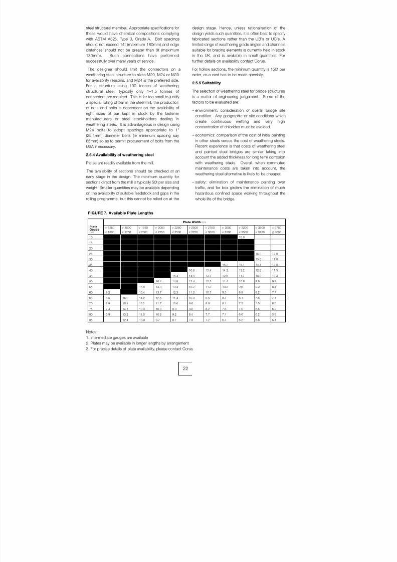
8/7/2019 52512003 Steel Bridges
http://slidepdf.com/reader/full/52512003-steel-bridges 30/96
steel structural member. Appropriate specifications for
these would have chemical compositions complying
with ASTM A325, Type 3, Grade A. Bolt spacings
should not exceed 14t (maximum 180mm) and edge
distances should not be greater than 8t (maximum
130mm). Such connections have performed
successfully over many years of service.
The designer should limit the connectors on aweathering steel structure to sizes M20, M24 or M30
for availability reasons, and M24 is the preferred size.
For a structure using 100 tonnes of weathering
structural steel, typically only 1–1.5 tonnes of
connectors are required. This is far too small to justify
a special rolling of bar in the steel mill; the production
of nuts and bolts is dependent on the availability of
right sizes of bar kept in stock by the fastener
manufacturers or steel stockholders dealing in
weathering steels. It is advantageous in design using
M24 bolts to adopt spacings appropriate to 1"
(25.4mm) diameter bolts (ie minimum spacing say
65mm) so as to permit procurement of bolts from the
USA if necessary.
2.5.4 Availability of weathering steel
Plates are readily available from the mill.
The availability of sections should be checked at an
early stage in the design. The minimum quantity for
sections direct from the mill is typically 50t per size and
weight. Smaller quantities may be available depending
on the availability of suitable feedstock and gaps in the
rolling programme, but this cannot be relied on at the
design stage. Hence, unless rationalisation of the
design yields such quantities, it is often best to specify
fabricated sections rather than the UB's or UC's. A
limited range of weathering grade angles and channels
suitable for bracing elements is currently held in stock
in the UK, and is available in small quantities. For
further details on availability contact Corus.
For hollow sections, the minimum quantity is 150t perorder, as a cast has to be made specially.
2.5.5 Suitability
The selection of weathering steel for bridge structures
is a matter of engineering judgement. Some of the
factors to be evaluated are:
– environment: consideration of overall bridge site
condition. Any geographic or site conditions which
create continuous wetting and very high
concentration of chlorides must be avoided.
– economics: comparison of the cost of initial painting
in other steels versus the cost of weathering steels.
Recent experience is that costs of weathering steel
and painted steel bridges are similar taking into
account the added thickness for long term corrosion
with weathering steels. Overall, when commuted
maintenance costs are taken into account, the
weathering steel alternative is likely to be cheaper.
– safety: elimination of maintenance painting over
traffic, and for box girders the elimination of much
hazardous confined space working throughout the
whole life of the bridge.
22
Notes:
1. Intermediate gauges are available
2. Plates may be available in longer lengths by arrangement
3. For precise details of plate availability, please contact Corus
FIGURE 7. Available Plate Lengths
10
15
20
25
30
35
40
45
50
55
60
65
70
75
80
85
18.3
18.3
18.3
18.3
18.3
17.0
17.0
17.0
17.0
17.0
9.2
8.5
7.9
7.4
6.9
18.3
18.3
18.3
18.3
18.3
18.3
17.0
17.0
17.0
17.0
17.0
16.2
15.1
14.1
13.2
12.4
18.3
18.3
18.3
18.3
18.3
18.3
17.0
17.0
17.0
16.8
15.4
14.2
13.2
12.3
11.5
10.9
18.3
18.3
18.3
18.3
18.3
17.0
17.0
17.0
16.4
14.9
13.7
12.6
11.7
10.9
10.3
9.7
18.3
18.3
18.3
18.3
17.0
17.0
17.0
16.4
14.8
13.4
12.3
11.4
10.6
9.9
9.2
8.7
18.3
18.3
18.3
18.3
17.0
17.0
16.8
14.9
13.4
12.2
11.2
10.3
9.6
9.0
8.4
7.9
18.3
18.3
18.3
18.3
17.0
17.0
15.4
13.7
12.3
11.2
10.3
9.5
8.8
8.2
7.7
7.2
18.3
18.3
18.3
17.0
17.0
16.2
14.2
12.6
11.4
10.3
9.5
8.7
8.1
7.6
7.1
6.7
10.0
18.3
18.3
17.0
17.0
15.1
13.2
11.7
10.6
9.6
8.8
8.1
7.5
7.0
6.6
6.2
15.0
15.0
14.1
12.3
10.9
9.9
9.0
8.2
7.6
7.0
6.6
6.2
5.8
12.0
12.0
12.0
11.5
10.3
9.2
8.4
7.7
7.1
6.6
6.2
5.8
5.4
> 1250
≤ 1500
> 1500
≤ 1750
> 1750
≤ 2000
> 2000
≤ 2250
> 2250
≤ 2500
> 2500
≤ 2750
> 2750
≤ 3000
> 3000
≤ 3200
> 3200
≤ 3500
> 3500
≤ 3750
> 3750
≤ 4000
PlateGauge(mm)
Plate Width (mm)

8/7/2019 52512003 Steel Bridges
http://slidepdf.com/reader/full/52512003-steel-bridges 31/96
3.1 Introduction
This chapter deals with the various practical aspects of the design and selection of the appropriate form of the
principal structural members in a steel or composite
construction bridge.
The simplest form uses rolled section universal beams
with little fabrication other than cutting to length,
welding of bearing stiffeners (discussed in more detail
below for plate girders), and welding of shear
connectors. As a characteristic of the rolling process,
most deep rolled beams have web thicknesses greater
than needed for structural purposes. Consequently
web stiffeners are rarely required; however, where they
are needed, web stiffeners should not be fullpenetration butt welded to the webs of rolled sections
because of the risk of lamination.
3.2 Plate Girders
Flange thicknesses limited to 75mm are generally
advisable to avoid weld procedures needing excessive
preheat; but flanges up to 100mm thickness or more
can be used subject to notch toughness requirements
and availability. Butt welds will be necessary for
forming long flanges, allowing the use of smaller plates
in regions of reduced moment; however, the number of
plate changes should be the minimum commensurate
with plate availability and economy, because of the
high cost of butt welds. Figure 8 is a guide as to where
it is economic to change plate thicknesses within
girder lengths. The Figure is typical for flanges or webs
of medium size plate girders. The relative economy
may vary in individual cases depending upon the
welding processes used and general fabrication
methods. It is usual to cut flange and web plates in
multiple widths from economic wide plates supplied
from the rolling mill.
Flanges should generally be as wide as possible
commensurate with outstand limits imposed by BS
5400: Part 3, so as to give maximum lateral stability.
Table 5 gives outstand limits for a common range of
compression flange thickness. Tension flanges are
limited to an outstand of twenty times thickness to
ensure suitably robust construction.
A typical plate girder for a single span bridge is shown
in Figure 9; because the span of 32.25m exceeded
27.4m an optional splice is shown towards one end.
Suitable bolted or welded splices are shown in Figure
10. In cases where the steelwork contractor can
deliver the girders to site in one length then the site
splice would be unnecessary.
23
CHAPTER 3
DESIGN OF MEMBERS
15
275
205
400
355
180
350
460
158
300
20
278
550
243
450
216
400
25
347
650
304
600
269
500
30
265
417
800
345
365
700
440
323
650
35
486
950
426
850
377
750
40
556
1100
487
950
431
850
45
637
1250
556
1100
491
1000
50
255
708
1400
335
618
1200
430
545
1100
55
779
1550
679
1350
654
1300
60
850
1700
741
1450
654
1300
65
939
1850
815
1600
726
1450
70
245
1011
2000
325
878
1750
410
782
1550
75
1083
2150
941
1850
837
1650
y (N/mm2 )
Outstand (mm)
Typ Fig
y (N/mm2 )
Outstand (mm)
Typ Fig
y (N/mm2 )
Outstand (mm)
Typ Fig
S275
S355
S460
Strength Grade Flange Thickness (mm)
o
o
o
TABLE 5 - Compression Outstand limit to Flanges (BS 5400: Part 3: 2000 Clause 9.3.)

8/7/2019 52512003 Steel Bridges
http://slidepdf.com/reader/full/52512003-steel-bridges 32/96
The steelwork contractor usually butt welds the flanges
and web plates to full length in the shop before
assembly of the girder. This means that such shop
joints can be in different positions in the two flanges
and do not have to line up with any shop joint in the
web.
The fabrication process for plate girders varies
between steelwork contractors depending on howextensively their workshops are equipped, from basic
facilities up to substantial automation. The alternatives
are described in the following common sequence (see
Figure 11) for plate girder preparation, assembly, and
finishing:
A. Butt weld plates for flanges and webs into longer
lengths as required, with the plate at full supplied
width, if possible, to minimise butt weld testing
requirements.
B. Mark ends and machine flame cut flanges to width
and length. If the girder is curved in plan then theflange will need to be profiled to the correct cut shape.
If it is possible with the equipment available, then drill
bolt holes for flange connections and mark stiffener
positions. If not, then these will need to be hand
marked and drilled later.
C. Machine flame cut welds to profile and camber,
including any fabrication precamber. If it is possible
with the equipment available, then drill bolt holes for
web connections and mark any longitudinal stiffener
positions. If not, then these will need to be hand
marked and drilled later.
D. Machine flame cut stiffeners to shape. If it is
possible with the equipment available, then drill bolt
holes for bracing connections and mark any plan
bracing cleat positions. If not, then these will need to
be hand marked and drilled later.
E. Assemble the girder
Either
Assemble flanges to web using tack welds, then semi-
automatically weld the flanges to the web, rotating the
girder as necessary to minimise distortion and obtain
the necessary welding position. (This is used for very
short girders, such as diaphragms, and highly shaped
girders.)
or
If ‘T + I’ automatic girder assembly equipment is
available, then automatically weld web to first flange to
form a ‘T’ section before turning the ‘T’ section over to
assemble and weld the second flange to the web
forming the ‘I’ girder.
or
If automatic girder assembly equipment is available,
then place the web horizontally between the twoflanges and automatically weld the two uppermost
web to flange welds before turning the girder to weld
the other side.
F. Tack in stiffeners (marking positions if necessary),
then fillet weld in place using manual, semi-automatic
or automatic (robotic) welding procedures as available
and appropriate.
G. Check tolerances to specification for the fabricated
girder.
H. Trial erect steelwork if required. With modern
fabrication techniques trial erections should only be
necessary if the implications of a minor problem on a
single connection is so critical as to justify the expense.
For example, any section of bridge being erected in
possession of a motorway or railway would normally
be trial erected and this should be specified by the
designer. Trial erections should not normally be
specified for ‘green field’ erection, but with some
designs it may be necessary to trial erect and carry out
the fitting and welding of some components beforedismantling. Seek advice from steelwork contractors if
necessary.
I. Blast steelwork and apply protective treatment to
specification, if required.
J. Pre-assemble braced pairs or longer lengths prior to
delivery to site, depending on erection method and site
access. This can sometimes be combined with trial
erection to minimise cost.
When designing plate girders, there is a temptation to
minimise the weight of the girder by minimising the
thickness of the web and introducing stiffeners atregular intervals along the web. This does not lead to
the most cost-effective design, as the workmanship
cost of profiling, fitting and welding these intermediate
stiffeners can outweigh the material costs saved in
reducing the web thickness. As a general rule,
intermediate stiffeners should only be provided where
permanent and temporary bracing members are
required, at say 8m to 10m centres longitudinally for a
multi girder design, with the web plate designed to
meet loading requirements unstiffened between the
bracing stiffeners - except at bearing or jacking
positions. Ladder beam designs are stiffened at cross
girder locations, generally 2.5m to 4.0m depending on
formwork design.
In design and detailing of web stiffeners for plate
girders, the welding should be carefully considered for
both bearing stiffeners and intermediate stiffeners.
Where stiffeners are closely spaced access for welding
must be considered: a reasonable rule is that the
space between two elements should be at least equal
to their depth. Thus for example, two stiffeners
150mm wide should be separated by at least 150mm.
Bearing (and jacking) stiffeners should be attached to
both flanges using fillet welds. These stiffeners shouldalso be ‘fitted’ to the loaded flange (usually the bottom
24
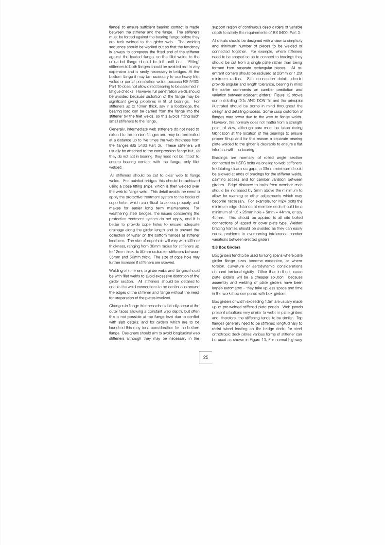
8/7/2019 52512003 Steel Bridges
http://slidepdf.com/reader/full/52512003-steel-bridges 33/96
flange) to ensure sufficient bearing contact is made
between the stiffener and the flange. The stiffeners
must be forced against the bearing flange before they
are tack welded to the girder web. The welding
sequence should be worked out so that the tendency
is always to compress the fitted end of the stiffener
against the loaded flange, so the fillet welds to the
unloaded flange should be left until last. ‘Fitting’
stiffeners to both flanges should be avoided as it is veryexpensive and is rarely necessary in bridges. At the
bottom flange it may be necessary to use heavy fillet
welds or partial penetration welds because BS 5400:
Part 10 does not allow direct bearing to be assumed in
fatigue checks. However, full penetration welds should
be avoided because distortion of the flange may be
significant giving problems in fit of bearings. For
stiffeners up to 10mm thick, say in a footbridge, the
bearing load can be carried from the flange into the
stiffener by the fillet welds; so this avoids fitting such
small stiffeners to the flange.
Generally, intermediate web stiffeners do not need to
extend to the tension flanges and may be terminatedat a distance up to five times the web thickness from
the flanges (BS 5400 Part 3). These stiffeners will
usually be attached to the compression flange but, as
they do not act in bearing, they need not be ‘fitted’ to
ensure bearing contact with the flange, only fillet
welded.
All stiffeners should be cut to clear web to flange
welds. For painted bridges this should be achieved
using a close fitting snipe, which is then welded over
the web to flange weld. This detail avoids the need to
apply the protective treatment system to the backs of
cope holes, which are difficult to access properly, andmakes for easier long term maintenance. For
weathering steel bridges, the issues concerning the
protective treatment system do not apply, and it is
better to provide cope holes to ensure adequate
drainage along the girder length and to prevent the
collection of water on the bottom flanges at stiffener
locations. The size of cope hole will vary with stiffener
thickness, ranging from 30mm radius for stiffeners up
to 12mm thick, to 50mm radius for stiffeners between
35mm and 50mm thick. The size of cope hole may
further increase if stiffeners are skewed.
Welding of stiffeners to girder webs and flanges should
be with fillet welds to avoid excessive distortion of the
girder section. All stiffeners should be detailed to
enable the weld connections to be continuous around
the edges of the stiffener and flange without the need
for preparation of the plates involved.
Changes in flange thickness should ideally occur at the
outer faces allowing a constant web depth, but often
this is not possible at top flange level due to conflict
with slab details; and for girders which are to be
launched this may be a consideration for the bottom
flange. Designers should aim to avoid longitudinal web
stiffeners although they may be necessary in the
support region of continuous deep girders of variable
depth to satisfy the requirements of BS 5400: Part 3.
All details should be designed with a view to simplicity
and minimum number of pieces to be welded or
connected together. For example, where stiffeners
need to be shaped so as to connect to bracings they
should be cut from a single plate rather than being
formed from separate rectangular pieces. All re-entrant corners should be radiused at 20mm or 1.25t
minimum radius. Site connection details should
provide angular and length tolerance, bearing in mind
the earlier comments on camber prediction and
variation between adjacent girders. Figure 12 shows
some detailing DOs AND DON’ Ts and the principles
illustrated should be borne in mind throughout the
design and detailing process. Some cusp distortion of
flanges may occur due to the web to flange welds.
However, this normally does not matter from a strength
point of view, although care must be taken during
fabrication at the location of the bearings to ensureproper fit-up and for this reason a separate bearing
plate welded to the girder is desirable to ensure a flat
interface with the bearing.
Bracings are normally of rolled angle section
connected by HSFG bolts via one leg to web stiffeners.
In detailing clearance gaps, a 30mm minimum should
be allowed at ends of bracings for the stiffener welds,
painting access and for camber variation between
girders. Edge distance to bolts from member ends
should be increased by 5mm above the minimum to
allow for reaming or other adjustments which may
become necessary. For example, for M24 bolts theminimum edge distance at member ends should be a
minimum of 1.5 x 26mm hole + 5mm = 44mm, or say
45mm. This should be applied to all site bolted
connections of lapped or cover plate type. Welded
bracing frames should be avoided as they can easily
cause problems in overcoming intolerance camber
variations between erected girders.
3.3 Box Girders
Box girders tend to be used for long spans where plate
girder flange sizes become excessive, or where
torsion, curvature or aerodynamic considerations
demand torsional rigidity. Other than in these cases
plate girders will be a cheaper solution because
assembly and welding of plate girders have been
largely automated – they take up less space and time
in the workshop compared with box girders.
Box girders of width exceeding 1.5m are usually made
up of pre-welded stiffened plate panels. Web panels
present situations very similar to webs in plate girders
and, therefore, the stiffening tends to be similar. Top
flanges generally need to be stiffened longitudinally to
resist wheel loading on the bridge deck; for steel
orthotropic deck plates various forms of stiffener can
be used as shown in Figure 13. For normal highway
25

8/7/2019 52512003 Steel Bridges
http://slidepdf.com/reader/full/52512003-steel-bridges 34/96
decks the stiffener to deck plate weld is highly fatigue
sensitive, and an 80% partial penetration butt weld is
essential: fillet welds for closed stiffeners may be
sufficient for low utilisation decks on Ro-Ro ramps for
example.
The shape of box girders needs to be retained during
fabrication by diaphragms at intervals which act as
formers, normally placed on one flange, followed by
assembly of the webs and other flange to them. Such
diaphragms should form bearing diaphragms and
intermediate frames as part of the permanent design.
A rough guide for maximum spacing is 3 x the box
depth to ensure that distortion (or lozenging) of the box
shape does not occur during fabrication or under
action of deck traffic loading. If sufficient diaphragms
are used then transverse bending of the longitudinal
corner welds under such loading is negligible and
partial penetration or fillet welds can be used. Full
penetration welds in such situations are feasible, but
are costly and less easy to guarantee. A suitable detailis to use a 6mm fillet weld inside the box (often done
as part of the assembly process) with external welds
being partial penetration single vee welds typically size
8mm. A further simplification is to oversail the top
flange and to use fillet welds both internally and
externally. Details should be devised to permit the
maximum amount of fabrication and protective
treatment prior to assembly of the box girders. Thus
internal diaphragms should allow for longitudinal
stiffeners to slot through. Diaphragms should
incorporate access holes of suitable dimensions for
final welding and to permit maintenance access with
due regard for safety and emergency situations. In
recognition of the designer’s responsibilities under
CDM regulations both during construction and in-
service, reference to health and safety guidelines is
necessary to confirm acceptable sizes of openings,
depending upon overall dimensions of the box and
length of escape routes. It is suggested that a
minimum size should be 500mm wide and 600mm
high. Wherever possible openings should be flush with
the bottom flange to permit movement of a stretcher in
emergency. Where a step is necessary, for example at
a bearing diaphragm, the height of this should be
minimised. During construction it should be
recognised that further temporary access holes for
welding may be necessary, often through webs; these
normally need to be reinstated with full penetration
welded infill plates on completion.
For small boxes, say less than 1.2m x 1.2m, the inside
should be permanently sealed by welding. For flanges
less than 1.2m wide, longitudinal stiffeners may be
avoided, simplifying the fabrication. Bridges
constructed of several such compact boxes can
eliminate the need for any exposed lateral bracings.
The fit up and fabrication of box girders requiresconsiderable skill and experience. For pre-fabricated
stiffened panels the longitudinal stiffeners are usually
welded first giving long runs where fully automatic
welding can be used to advantage. The plate must be
clamped down to avoid the inevitable weld shrinkage
on its upper surface from distorting the plate. The
clamps are retained until the transverse stiffeners have
been welded in. Some steelwork contractors use
automated equipment to produce orthotropic stiffenedplate panels in bulk economically to high quality.
For corner welds the box may have to be turned over
in the shop, after making the first two welds, to
complete the second pair.
The hollow towers of cable-stayed and suspension
bridges as well as the ribs of some arch bridges
undergo stresses predominantly in compression. The
site joints can be made by machining the ends of the
components and the load is then transferred by direct
bearing, the bolts or site welds being nominal for
location and to carry any shear forces. In these cases
machining needs to be done after fabrication to
overcome distortion due to welding. Drawings should
clearly state that the end plate thickness quoted is
"after machining".
3.4 Bearings
For many steel bridges it is convenient to use
proprietary bearings, which are economic where
sliding together with rotation about both axes is to be
accommodated. The PTFE and/or elastomeric
materials within these bearings are able to deal
efficiently with low sliding friction (5% typical) and
articulation. In cases where uplift, excessive rotation orrestraint about one axis only has to be
accommodated, steel fabricated bearings may be
more economic and suitable. In cases of uplift, a
separate device or fabrication which resists upward
forces may be preferable, for example, in resisting
vehicle impact on bridge soffits. Long span bridges
generally require special bearings, such as pendel links
or enlarged versions of proprietary disc or spherical
type. All bearings must be capable of replacement
during the design life of the bridge and it is prudent to
provide for jacking at supports. Given the designer's
obligations for maintenance under CDM he shouldprovide sufficient space and support for jacking to be
carried out, including jacking stiffeners on the
steelwork if necessary.
Proprietary pot or disc type bearings are suitable for
most short and medium span bridges at fixed and free
locations. They occupy minimal space and are
normally bolted to the steelwork through a tapered
steel bearing plate, to take up longitudinal gradient of
the girder due to camber and overall geometry, such
that the bearing is truly horizontal in the completed
bridge. The bearing plate accommodates any
departures from flatness of the flange: it is machinedso as to form the taper and to achieve a flat surface for
26
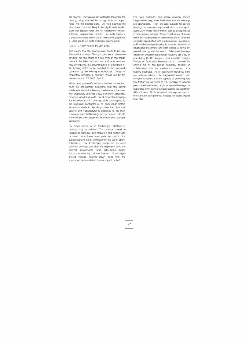
8/7/2019 52512003 Steel Bridges
http://slidepdf.com/reader/full/52512003-steel-bridges 35/96
the bearing. They are usually welded to the girder, the
bearing being attached by through bolts or tapped
holes into the bearing plate. At fixed bearings the
attachment bolts are likely to be significantly loaded
such that tapped holes are not satisfactory without
sufficient engagement length. In such cases a
conservative assessment of the minimum engagement
is, using grade 8.8 bolts and S355 bearing plate:
0.9d x = 1.62d or 39m for M24 bolts.
This means that the bearing plate needs to be, say,
45mm thick at least. Through bolts are an alternative
solution, but the effect of holes through the flange
needs to be taken into account and taper washers
may be required. It is good practice for a template of
the bearing holes to be supplied to the steelwork
contractor by the bearing manufacturer. Design of
proprietary bearings is normally carried out by the
manufacturer to BS 5400: Part 9.
At free bearings the effect of eccentricity of the reactionmust be considered, assuming that the sliding
interface is above the bearing interface as is the case
with proprietary bearings unless they are inverted and
provided with debris skirts. For all proprietary bearings
it is important that full bearing details are supplied to
the steelwork contractor at an early stage before
fabrication starts in the shop: often the choice of
bearing and manufacturer is entrusted to the main
contractor such that bearings are not ordered until late
in the construction stage and late information disrupts
fabrication.
For small spans, or in footbridges, elastomericbearings may be suitable. The bearings should be
retained in place by keep strips top and bottom and
mounted on a lower steel plate secured to the
substructure, or as an alternative by the use of epoxy
adhesives. For footbridges supported by steel
columns bearings can often be dispensed with, the
thermal movements and articulation being
accommodated by column flexure. Footbridges
should include holding down bolts into the
superstructure to resist accidental impact or theft.
For fixed bearings, and where rotation occurs
longitudinally only, steel fabricated knuckle bearings
are appropriate. They are also suitable for all the
bearings in abutment supported short spans up to
about 20m where higher friction can be accepted, as
in many railway bridges. They consist simply of a steel
block with radiused upper surface welded on to a steel
spreader plate bolted to the substructure. In cases of uplift a fabricated pin bearing is suitable. Where both
longitudinal movement and uplift occurs a swing link
pinned bearing can be used. Fabricated bearings
which can accommodate larger rotations are used in
articulating Ro-Ro linkspans and movable bridges.
Design of fabricated bearings would normally be
carried out by the bridge designer, possibly in
collaboration with the steelwork contractor, or a
bearing specialist. Roller bearings of hardened steel
are suitable where only longitudinal rotation and
movement occurs and are capable of achieving very
low friction values down to 1%, suitable on slender
piers: to reduce bearing height as special bearings the
upper and lower curved surfaces can be radiused from
different axes. Such fabricated bearings are used in
the standard box girder rail bridges for spans greater
than 20m.
27
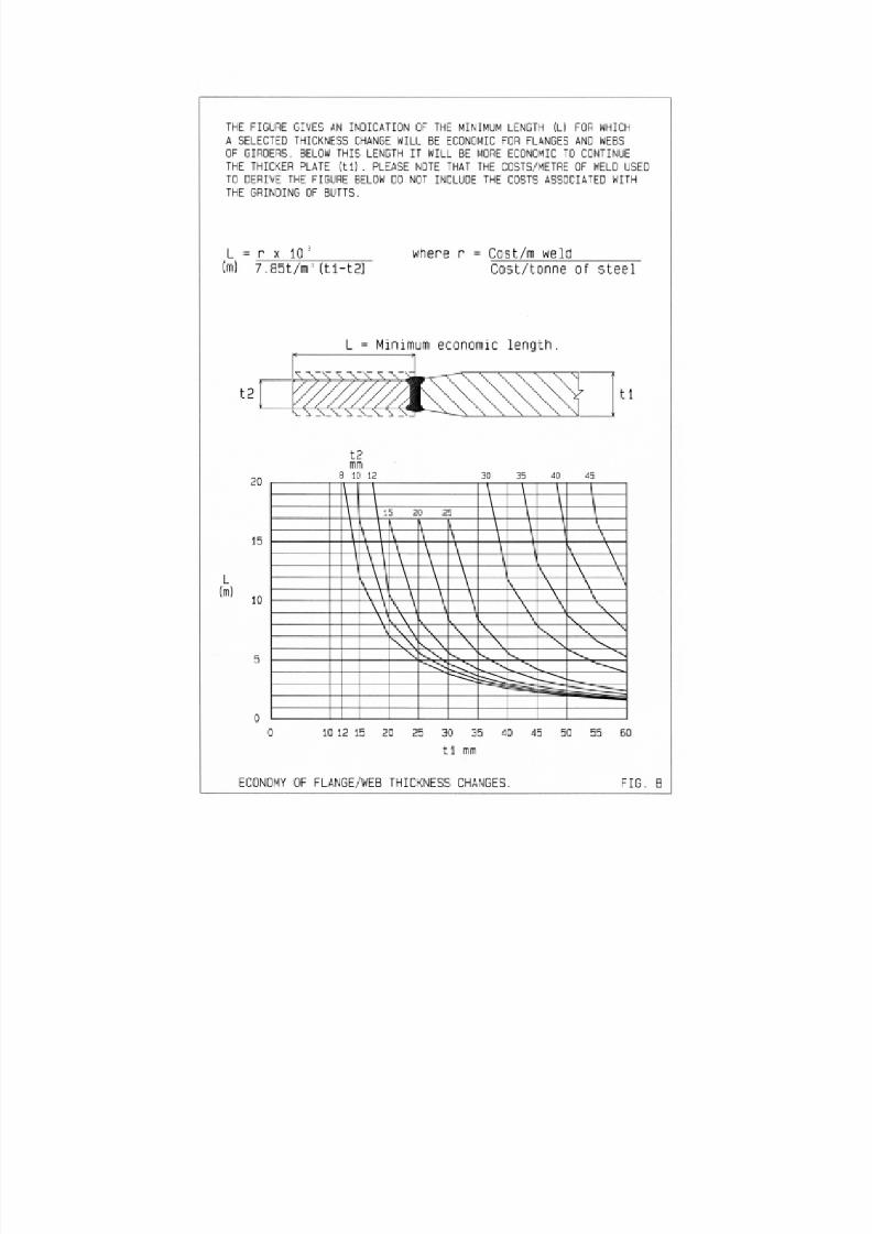
8/7/2019 52512003 Steel Bridges
http://slidepdf.com/reader/full/52512003-steel-bridges 36/96
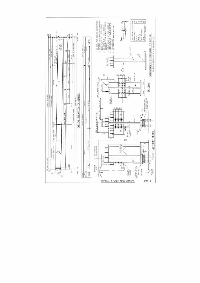
8/7/2019 52512003 Steel Bridges
http://slidepdf.com/reader/full/52512003-steel-bridges 37/96
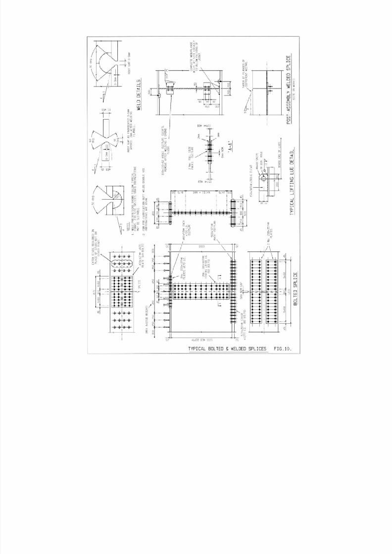
8/7/2019 52512003 Steel Bridges
http://slidepdf.com/reader/full/52512003-steel-bridges 38/96
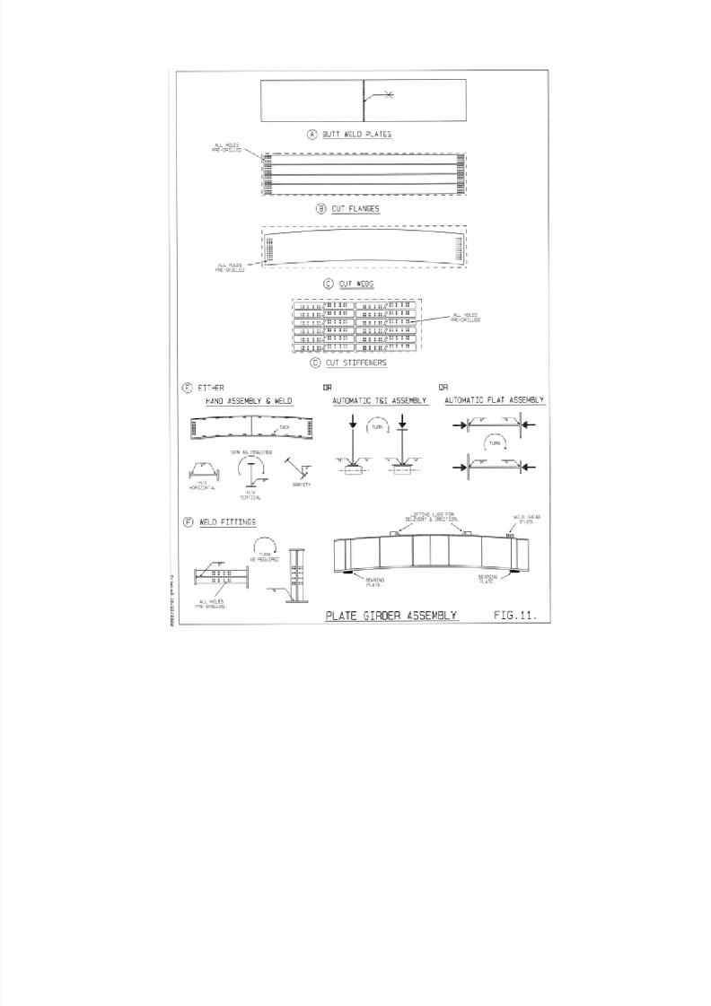
8/7/2019 52512003 Steel Bridges
http://slidepdf.com/reader/full/52512003-steel-bridges 39/96

8/7/2019 52512003 Steel Bridges
http://slidepdf.com/reader/full/52512003-steel-bridges 40/96
32
8/7/2019 52512003 Steel Bridges
http://slidepdf.com/reader/full/52512003-steel-bridges 41/96
4.1 Introduction
In general shop connections for short and mediumspan steel bridges are made by welding and site
connections by bolting. Bolting is generally to be
preferred for the site connections for it can be carried
out more quickly than welding, and with less
interruption to the flow of erection. Where the job is
large, all the impediments and costs of site welding,
with its attendant plant, extra tradespeople, testing,
protection of joints, temporary restraints and quality
management can be spread sufficiently to achieve
relative economy. For small jobs the Designer must
have very good cause to specify site welding. Where
welding is used for site connections then often this is
for principal connections in main girders, whilst
secondary members are more conveniently bolted.
Typical site connections for a plate girder, either bolted
or welded, are shown in Figure 10.
Much of the workmanship in steel bridge erection is
taken up in assembling minor components and making
the connections. It is important that the Designer, in
making choices and detail design for connections,
should visualise how all the components can be
assembled and how the tradesmen can carry out the
bolting or welding. In some arrangements it is easy to
design components which cannot be fitted, bolts
which cannot be tightened with standard equipment,
and position welds which are very arduous for the
welder and costly for the project. Where the Designer
has difficulty in arriving at a practicable solution which
meets his design criteria, he should consult an
experienced steel bridge contractor.
4.2 Bolted Connections
The use of high strength friction grip (HSFG) bolts is
mandatory under BS 5400 for all traffic loaded
connections, to give full rigidity. Untensioned bolts of
mild steel (grade 4.6) and high tensile steel (grade 8.8)
in clearance holes may be used in footbridges, inelements which do not receive highway or railway
traffic loading such as parapets, and for temporary
works.
Countersunk HSFG bolts should not be used, except
where a flush finish is absolutely essential for functional
(not aesthetic) reasons. Similarly, the use of set screws
or set bolts in tapped holes should be avoided
because difficulties can arise in achieving accurate
alignment and damage free holes and threads:
difficulties may also arise in matching the strength of
the threads in the main material with that of the threads
on the fastener, particularly when using a high tensile
steel fastener for its strength in tension with small
thread engagement.
All lapped or cover plate connections should have
tolerance in length to allow for site adjustments: thus
at member ends, including bracings and bolted girder
splices, the minimum edge distance prescribed in BS
5400: Part 3 should be increased by at least 5mm as
described in 3.2. End plate type connections are
convenient for cross girders in half-through bridges
where they can automatically square up the main
girders during erection; but they are generally more
costly to fabricate as end plates need machining to
achieve proper contact. End plates do not give
freedom in interconnection of multiple braced girders
where camber differences may be critical to fit up.
4.3 High Strength Friction Grip Bolts
Two types of HSFG bolts (known as pre-loaded bolts
in Eurocodes) are specified in BS 4395 :
– General Grade bolts to BS 4395: Part 1, which
account for most of those used, and have a good
compromise of high strength and ductility.
Mechanical properties are similar to 8.8 grade for
sizes up to and including M24; but to continue in this
grade for larger sizes would mean the use of an alloy
rather than a carbon steel and so the strength is
reduced for sizes over M24 for economy. The bolts
are tightened to give a shank tension of at least the
specified proof load.
– Higher Grade bolts to BS 4395: Part 2 are made of
10.9 grade material which means the ductility is
lower than for the general grade. The limited
extensibility could lead to breakage or strain cracking
in the threads from the combined action of axial
tension and applied torque during tightening if the
bolt were overstressed. BS 5400: Part 3 limits the
assumed bolt tension to only 0.85 times the proof
load of the bolt and reduces the slip factors by 10%.
BS 4604: Part 2 covering the use of higher grade
bolts restricts them to joints subjected to shear
alone.
4.4 The Friction Grip Joint
The friction grip joint depends for its performance on
the tightening of HSFG bolts to the specified shank
tensions so that the adjoining plies are brought into
close contact and the shear load is transferred by
friction at the interfaces.
Frictional resistance at the interface is highly
dependent on the surface conditions. Certain types of
surface treatment result in very low slip factors and
33
CHAPTER 4
CONNECTIONS
8/7/2019 52512003 Steel Bridges
http://slidepdf.com/reader/full/52512003-steel-bridges 42/96

8/7/2019 52512003 Steel Bridges
http://slidepdf.com/reader/full/52512003-steel-bridges 43/96
applied to the bolt shank itself during tightening which
mitigates the concern about higher grade bolts in
tension. If the bolts are assumed to be general grade
bolts it is satisfactory to use them to carry tension.
4.5.4 Sequence of Tightening
Whichever method of bolt tightening is chosen, bolts
and nuts should always be tightened in a staggered
pattern and when a bolt group comprises more than
four bolts, tightening should be from the middle of the
joint outwards and ensuring that all the plies are
properly pulled together in full contact.
If due to any cause a bolt or nut is slackened off after
final tightening, the bolt, nut and washer must be
discarded and not reused.
4.6 Inspection of HSFG Bolts
Identification markings on the bolt head and nut should
be checked and the use of an appropriate hardened
washer under the rotated nut or bolt head verified.
Where necessary, the use and correct positioning of
taper washers should be checked.
With the part turn method it is necessary to ensure that
the nut has been rotated sufficiently relative to the bolt.
With the torque control method a random sample of
tightened bolts should be selected for checking, which
is most easily carried out by re-calibrating the wrench
to give the required shank tension and then setting the
torque reading 5% above this figure. This should not
move the nuts further.
With the ‘Coronet’ load indicator method it isnecessary to ensure that the average specified gap
between the load indicating washer and the bolt head
has been reached.
In large bolt groups there is always a danger that on
bedding down of the connected plies, some of the first
bolts to be tightened may have lost some of their
preload. This is not always apparent in the case of
normal inspection procedures for Part Turn and Direct
Tension Indication, so it is of paramount importance
that tightening, inspection and any remedial measures
in such situations are carried out in strict compliance
with the contract supervisor’s instructions.
4.7 Welded Connections
In-line web to web and flange to flange connections
generally need to develop the full capacity of the
elements and should be full penetration butt welds.
If a section change occurs the larger plate should, for
fatigue reasons, be tapered in thickness and width at a
maximum slope of 1 in 4 down to that of the smaller.
Where double-vee preparations are used it is
unnecessary to form a taper where the ‘step’ is 2mm
or less because this can be incorporated within the
width of the weld. At changes of flange thickness the
taper should be provided to one face only (see also 3.2
and Figure 10). Weld preparation form and details
should normally be determined by the steelwork
contractor, based on approved weld procedures.
Unless absolutely vital for fatigue reasons or to remove
corrosion traps on weatheriing steel, grinding flush at
welds should not be specified because of restrictions
in meeting safety legislation requirements: in most
cases fatigue performance will be governed by other
adjacent details such as web to flange and stiffener
welds such that undressed welds are acceptable, -
they also have the advantage of being visibly
identifiable in-service.
At flange site welds a cope hole (see Figure 10) should
be provided to the web with minimum radius of 40mm
(or 1.25 x web thickness if greater) to allow welding
access. Such cope holes should be left open on
completion and not filled with a welded insert, which
may cause excessive restraint effects.
Generally the designer should seek to use fillet welds
for all other welded connections, rather than full
penetration butt welds which usually are not justified
except in exceptional cases for fatigue reasons. Full
penetration welds tend to cause distortion, which is
particularly critical for end plate type connections; and,
they are relatively costly due to the operations involved
in forming weld preparations, multiple weld runs
involving back gouging, measures to reduce distortion,
and requirements for testing. Where a design requires
fillet welds larger than 15mm x 15mm it is preferable to
use partial penetration butt welds, reinforced where
necessary by fillet welds - for example at the lower
ends of bearing stiffeners where the welds may becritical for fatigue.
Generally fillet welds should be at least 5mm or 6mm
leg length other than in footbridges or parapet
construction where smaller welds of maximum 2/3 x
plate thickness will be more suitable to minimise
distortion in the thinner sections. On long continuous
welds, such as web to flange fillet welds, up to 10mm
fillet may be the optimum and suitable for laying in a
single pass using the submerged arc processes.
Advantage should be taken of the penetration, which
is achievable on fillet welds using automatic weld
processes. Where procedure trials are able to showthat a given penetration is consistently achieved then
this can be included in the throat dimension assumed
for design. BS 5400 Part 3 allows a root penetration
of 0.2 x throat (but not more than 2mm) to be assumed
without any need for trials if the submerged arc
process is used.
35

8/7/2019 52512003 Steel Bridges
http://slidepdf.com/reader/full/52512003-steel-bridges 44/96
36

8/7/2019 52512003 Steel Bridges
http://slidepdf.com/reader/full/52512003-steel-bridges 45/96
5.1 Introduction
The object of this chapter is to discuss the accuracy of steel fabrication and its significance for the designer as
well as for construction.
The dimensions of any artefact vary from those defined
by the designer: such variations stem from the nature
and behaviour of the material as much as from the
process of making it. Modern steel fabrication involves
the manufacture of large and often complex welded
assemblies of components from rolled steel products:
high temperature processes are used to make the
steel products to form the components and join them
together so dimensional variation from the design is
inherent and unavoidable. This behaviour hasimplications for the designer, for the steelwork
contractor, and for the bridge builder and each has to
anticipate the variations in carrying out their role. The
important questions are - which dimensional variations
are significant, what limits must be put on those which
are significant, and how should variations be managed
to ensure that the design is implemented to meet its
performance requirements without delay?
In steel bridge construction dimensional variation is
significant in a number of ways for it involves precise
mechanical components, structural steelwork
manufactured remote from the site, and civilengineering works. These interface with each other
and yet their precision varies from the highly accurate
to the inaccuracies inherent in placing concrete. It is
convenient to distinguish between:
• Mechanical fit which is vital for example for function
between nut and bolt, between bearing and girder,
between machined faces of compression members.
• Fit up of fabricated members which is essential for
efficient assembly for example of a bolted site splice,
yet the dimensional accuracy of the bolt group is
immaterial to the strength.
• Deviation from flatness or straightness which affects
the strength or function of components for example
in reduced buckling capacity.
• Accuracy of assembly at site where steel spans
must match the substructure positions and girder
profiles must correspond to maintain deck slab
thicknesses.
• Interface with substructures where the designer has
to provide adjustment in construction, say by large
H.D. bolt pockets and variable grout layers to
accommodate relatively inaccurate concrete to
precise steel components.
The control of dimension by tolerancing is fundamental
to the mechanical engineering discipline without which
no mechanism could work, no parts would be
interchangeable: no mechanical drawing is complete
without tolerances on all dimensions, limits and fits on
mating parts, and flatness tolerances on surfaces. In
contrast civil engineering construction has largely
ignored the concept of tolerancing, depending on the
calibration of its metrology to build the product
satisfactorily in situ. Historically steel fabrication found
a workable compromise making large manufactured
products using workshop techniques which assured
their efficient assembly at a remote site – tolerancing
has not been part of that process as a rule, it was
implicit in much of the work and explicit only formechanical bridge parts. Indeed the level of accuracy
common to a mechanical engineering workshop is
generally unnecessary for steel bridgework – for which
it has to be justified because it comes at a substantial
cost and needs special facilities, including machining.
For example the variation of flatness and thickness of
a steel plate from the rolling mill is perfectly satisfactory
for a girder, but it would be unnacceptable for a
machine part. With the widespread use of automated
processes from the 1980's for plate preparation, hole
drilling, girder assembly and welding, the geometrical
accuracy to which steel fabrication can be made has
much improved: this has been driven by the
economics of practicable manufacture and the
replacement of labour intensive traditional practice.
A demand for formal tolerances in steel bridge work
was first put forward in 1968 when a committee was
set up to revise the then bridge standard BS 153. The
need was highlighted in the investigations following the
collapse of the Milford Haven and West Gate (Yarra,
Australia) box girder bridges in 1970 when the
Merrison Committee produced the Interim Design
Workmanship Rules (IDWR) in February 1973 for box
girder bridges. These rules contained limits forimperfections including the flatness of plate panels and
straightness of stiffeners which were shown to
significantly affect the design capacity against
buckling.
For each new job the steelwork contractor will assess
the design to determine how best to undertake the
fabrication and control dimensions to ensure proper fit
up and assembly at site. For box girders in particular
and large bridges with steel decks, this may well
include a project-specific regime of dimensional
tolerances on sub-assemblies such as deck panels:
these would be compatible with the tolerances set bythe designer for the finished bridge.
37
CHAPTER 5
FABRICATION

8/7/2019 52512003 Steel Bridges
http://slidepdf.com/reader/full/52512003-steel-bridges 46/96
The following sections concentrate on the fabrication
process, the behaviour of steel in fabrication, and
those aspects of accuracy which bear particularly on
the strength of members and the shape of
components, and are of primary concern to the
designer.
5.2 Fabrication Tolerances
The fabrication tolerances and workmanship levels
defined explicitly in BS 5400 Part 6 have been
developed from a considerable amount of theoretical
and practical investigations. It should be appreciated
that most of the tolerances as stated apply only to
some elements of the structure and are required from
considerations of strength only: by themselves they do
not address the purposes of appearance and fit up,
and it is for the individual steelwork contractor to
choose his own additional standards for these. The
tolerances in Table 5 of Part 6 are compatible with the
design rules given in BS 5400 Part 3, but are generally
enhanced by 20% to allow for any uncertainties in
measurement and interpretation. The non dimensional
presentation of the strength rules contained in Part 3
enable some of the tolerances to be related to the steel
grade.
Plate flatness tolerances apply to the webs of plate
and box girders and to the panels of stiffened
compression flanges and box columns. The tolerance
refers to the flatness at right angles to the plate
surface, measured parallel to the longer side and a
simple expression is given relating the tolerance to the
gauge length of measurement. The tolerances in BS
5400 Part 6 are at least double the conservative values
which had been specified by the Merrison Rules.
Straightness tolerances are applied to longitudinal
compression flange stiffeners in box girders, box
columns and orthotropic decks and to all web
stiffeners in plate and box girders. Measurements at
the time of introduction of BS 5400: Part 6 on six
bridges showed that 97.5% of stiffeners and plate
panels would satisfy the tolerances.
The tolerance on the bow of compression members is
linked with the assumptions made in the design and
was developed from an extensive programme of
practical tests and theoretical investigations based on
an assumed sinusoidal bow of length/1000. The
tolerance on the straightness of individual flanges of
rolled and fabricated girders is related to the reduction
in the strength of the girder due to lateral torsional
buckling and the twisting moment at the support that
can be caused by an overall bow of the girder. The
tolerance on the flatness of rolled webs is related to the
strength of the web acting as a strut under points of
concentrated loading.
5.3 Checking of Deviations
The potential difficulty associated with working to
specified tolerances is the amount of checking
required in the fabrication shop. The specification of
reasonable tolerances should not increase fabrication
costs as a good steelwork contractor should be able
to comply with the values without special procedures
or rectification measures. However, as well as the
direct cost of checking, costs can be incurred when
checking activities delay the work-piece from entering
the next phase of production: checking adds time and
cost to the overall fabrication process.
Normally all member components are visually
examined by the steelwork contractor qualitatively for
deviations in excess of the specified tolerances and
any parts quantitatively checked where necessary.
This is a safeguard to ensure that obvious excessive
deviations, not caught within the representative 5% or
10% sampling specified by BS 5400: Part 6, do not
escape. For those member components where only
representative checks are required, the Engineer is
required to specify the areas where half of the checksare to be made. These will be in critical areas where
the steelwork is fully or nearly fully stressed and the
strength is sensitive to imperfection. The remainder of
the checks are to be made in areas selected at random
by the Engineer. 100% checking is required for the
overall straightness of columns, struts and girders, and
the webs of rolled sections at internal supports.
In making any checks the scanning device is to be
placed so that local surface irregularities do not
influence the results. The checks are performed on
completion of fabrication, and then at site on
completion of each site joint; local checks have to bemade on flatness of plate panels and straightness of
stiffeners. It is clear that the verticality of webs at
supports can only be checked during any trial erection
of the steelwork or after erection at site. For the end
supports of significantly skewed multiple I-beam
bridges (skew angle exceeding say 30o ) significant
twist of the girders is likely to occur when dead loads
are applied especially from concrete deck slabs. This
arises from the incompatibility between the deflection
of adjacent interconnected girders. In such cases the
designer should either supply values for the predicted
twist (along with the specified precamber information –
see 1.6) for adding to the specified verticality tolerance,
or alternatively specify that girders are to be pre-
twisted at site so as to counteract the twist due to
dead loads. For further advice refer to Steel Bridge
Group Guidance Note 7.03.
Where the tolerances specified in BS 5400 Part 6 are
exceeded remedial actions may be taken to remove
the distortion such as by heat or other straightening
measures. In some cases where this is difficult or
impracticable the information is submitted to the
designer for consideration. Often further analytical
checks which consider the actual deviation may show
that this is acceptable. In the case of plate panels,
38
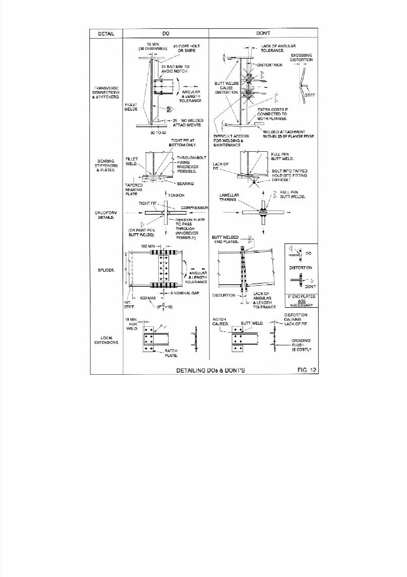
8/7/2019 52512003 Steel Bridges
http://slidepdf.com/reader/full/52512003-steel-bridges 47/96
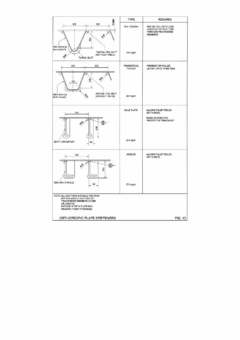
8/7/2019 52512003 Steel Bridges
http://slidepdf.com/reader/full/52512003-steel-bridges 48/96

8/7/2019 52512003 Steel Bridges
http://slidepdf.com/reader/full/52512003-steel-bridges 49/96
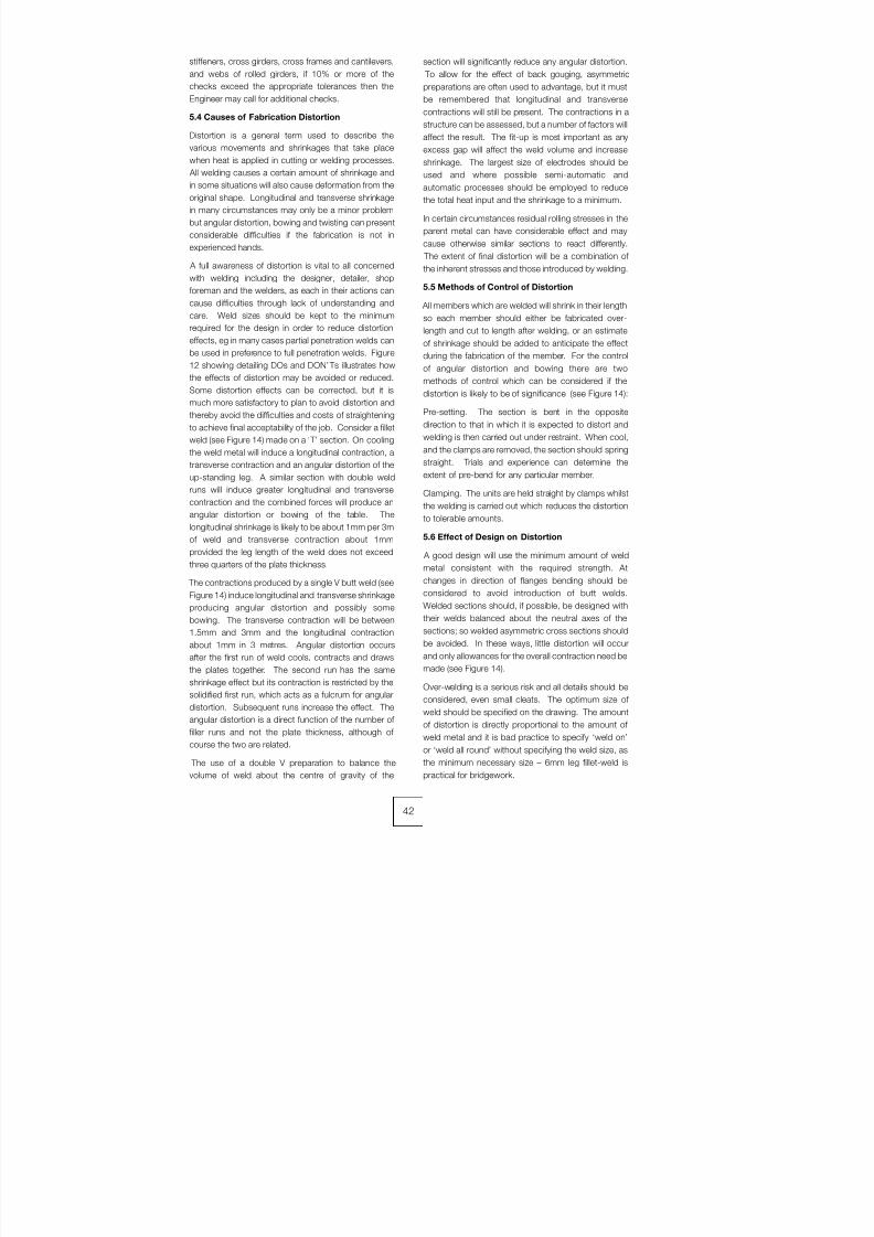
8/7/2019 52512003 Steel Bridges
http://slidepdf.com/reader/full/52512003-steel-bridges 50/96
stiffeners, cross girders, cross frames and cantilevers,
and webs of rolled girders, if 10% or more of the
checks exceed the appropriate tolerances then the
Engineer may call for additional checks.
5.4 Causes of Fabrication Distortion
Distortion is a general term used to describe the
various movements and shrinkages that take place
when heat is applied in cutting or welding processes.
All welding causes a certain amount of shrinkage and
in some situations will also cause deformation from the
original shape. Longitudinal and transverse shrinkage
in many circumstances may only be a minor problem
but angular distortion, bowing and twisting can present
considerable difficulties if the fabrication is not in
experienced hands.
A full awareness of distortion is vital to all concerned
with welding including the designer, detailer, shop
foreman and the welders, as each in their actions can
cause difficulties through lack of understanding andcare. Weld sizes should be kept to the minimum
required for the design in order to reduce distortion
effects, eg in many cases partial penetration welds can
be used in preference to full penetration welds. Figure
12 showing detailing DOs and DON’ Ts illustrates how
the effects of distortion may be avoided or reduced.
Some distortion effects can be corrected, but it is
much more satisfactory to plan to avoid distortion and
thereby avoid the difficulties and costs of straightening
to achieve final acceptability of the job. Consider a fillet
weld (see Figure 14) made on a ‘ T’ section. On cooling
the weld metal will induce a longitudinal contraction, a
transverse contraction and an angular distortion of the
up-standing leg. A similar section with double weld
runs will induce greater longitudinal and transverse
contraction and the combined forces will produce an
angular distortion or bowing of the table. The
longitudinal shrinkage is likely to be about 1mm per 3m
of weld and transverse contraction about 1mm
provided the leg length of the weld does not exceed
three quarters of the plate thickness.
The contractions produced by a single V butt weld (see
Figure 14) induce longitudinal and transverse shrinkage
producing angular distortion and possibly somebowing. The transverse contraction will be between
1.5mm and 3mm and the longitudinal contraction
about 1mm in 3 metres. Angular distortion occurs
after the first run of weld cools, contracts and draws
the plates together. The second run has the same
shrinkage effect but its contraction is restricted by the
solidified first run, which acts as a fulcrum for angular
distortion. Subsequent runs increase the effect. The
angular distortion is a direct function of the number of
filler runs and not the plate thickness, although of
course the two are related.
The use of a double V preparation to balance thevolume of weld about the centre of gravity of the
section will significantly reduce any angular distortion.
To allow for the effect of back gouging, asymmetric
preparations are often used to advantage, but it must
be remembered that longitudinal and transverse
contractions will still be present. The contractions in a
structure can be assessed, but a number of factors will
affect the result. The fit-up is most important as any
excess gap will affect the weld volume and increaseshrinkage. The largest size of electrodes should be
used and where possible semi-automatic and
automatic processes should be employed to reduce
the total heat input and the shrinkage to a minimum.
In certain circumstances residual rolling stresses in the
parent metal can have considerable effect and may
cause otherwise similar sections to react differently.
The extent of final distortion will be a combination of
the inherent stresses and those introduced by welding.
5.5 Methods of Control of Distortion
All members which are welded will shrink in their lengthso each member should either be fabricated over-
length and cut to length after welding, or an estimate
of shrinkage should be added to anticipate the effect
during the fabrication of the member. For the control
of angular distortion and bowing there are two
methods of control which can be considered if the
distortion is likely to be of significance (see Figure 14):
Pre-setting. The section is bent in the opposite
direction to that in which it is expected to distort and
welding is then carried out under restraint. When cool,
and the clamps are removed, the section should spring
straight. Trials and experience can determine the
extent of pre-bend for any particular member.
Clamping. The units are held straight by clamps whilst
the welding is carried out which reduces the distortion
to tolerable amounts.
5.6 Effect of Design on Distortion
A good design will use the minimum amount of weld
metal consistent with the required strength. At
changes in direction of flanges bending should be
considered to avoid introduction of butt welds.
Welded sections should, if possible, be designed with
their welds balanced about the neutral axes of the
sections; so welded asymmetric cross sections should
be avoided. In these ways, little distortion will occur
and only allowances for the overall contraction need be
made (see Figure 14).
Over-welding is a serious risk and all details should be
considered, even small cleats. The optimum size of
weld should be specified on the drawing. The amount
of distortion is directly proportional to the amount of
weld metal and it is bad practice to specify ‘weld on’
or ‘weld all round’ without specifying the weld size, as
the minimum necessary size – 6mm leg fillet-weld ispractical for bridgework.
42
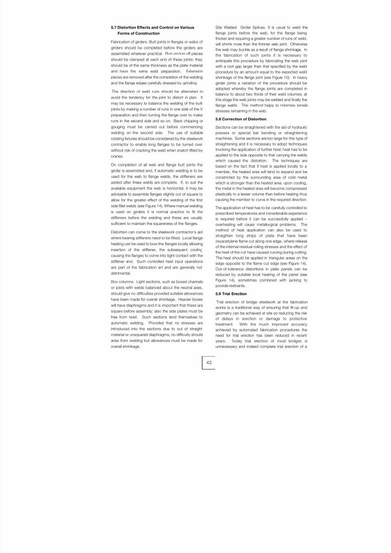
8/7/2019 52512003 Steel Bridges
http://slidepdf.com/reader/full/52512003-steel-bridges 51/96
5.7 Distortion Effects and Control on Various
Forms of Construction
Fabrication of girders. Butt joints in flanges or webs of
girders should be completed before the girders are
assembled wherever practical. Run-on/run-off pieces
should be clamped at each end of these joints: they
should be of the same thickness as the plate material
and have the same weld preparation. Extension
pieces are removed after the completion of the welding
and the flange edges carefully dressed by grinding.
The direction of weld runs should be alternated to
avoid the tendency for the joint to distort in plan. It
may be necessary to balance the welding of the butt
joints by making a number of runs in one side of the V
preparation and then turning the flange over to make
runs in the second side and so on. Back chipping or
gouging must be carried out before commencing
welding on the second side. The use of suitable
rotating fixtures should be considered by the steelwork
contractor to enable long flanges to be turned over
without risk of cracking the weld when snatch lifted by
cranes.
On completion of all web and flange butt joints the
girder is assembled and, if automatic welding is to be
used for the web to flange welds, the stiffeners are
added after these welds are complete. If, to suit the
available equipment the web is horizontal, it may be
advisable to assemble flanges slightly out of square to
allow for the greater effect of the welding of the first
side fillet welds (see Figure 14). Where manual welding
is used on girders it is normal practice to fit the
stiffeners before the welding and these are usually
sufficient to maintain the squareness of the flanges.
Distortion can come to the steelwork contractor’s aid
where bearing stiffeners need to be fitted. Local flange
heating can be used to bow the flanges locally allowing
insertion of the stiffener, the subsequent cooling
causing the flanges to come into tight contact with the
stiffener end. Such controlled heat input operations
are part of the fabrication art and are generally not
detrimental.
Box columns. Light sections, such as boxed channels
or joists with welds balanced about the neutral axes,
should give no difficulties provided suitable allowances
have been made for overall shrinkage. Heavier boxes
will have diaphragms and it is important that these are
square before assembly: also the side plates must be
free from twist. Such sections lend themselves to
automatic welding. Provided that no stresses are
introduced into the sections due to out of straight
material or unsquared diaphragms, no difficulty should
arise from welding but allowances must be made foroverall shrinkage.
Site Welded Girder Splices. It is usual to weld the
flange joints before the web, for the flange being
thicker and requiring a greater number of runs of weld,
will shrink more than the thinner web joint. Otherwise
the web may buckle as a result of flange shrinkage. In
the fabrication of such joints it is necessary to
anticipate this procedure by fabricating the web joint
with a root gap larger than that specified by the weldprocedure by an amount equal to the expected weld
shrinkage of the flange joint (see Figure 10). In heavy
girder joints a variation of the procedure should be
adopted whereby the flange joints are completed in
balance to about two thirds of their weld volumes; at
this stage the web joints may be welded and finally the
flange welds. This method helps to minimise tensile
stresses remaining in the web.
5.8 Correction of Distortion
Sections can be straightened with the aid of hydraulic
presses or special bar bending or straightening
machines. Some sections are too large for this type of
straightening and it is necessary to adopt techniques
involving the application of further heat: heat has to be
applied to the side opposite to that carrying the welds
which caused the distortion. The techniques are
based on the fact that if heat is applied locally to a
member, the heated area will tend to expand and be
constricted by the surrounding area of cold metal
which is stronger than the heated area: upon cooling,
the metal in the heated area will become compressed
plastically to a lesser volume than before heating thus
causing the member to curve in the required direction.
The application of heat has to be carefully controlled to
prescribed temperatures and considerable experience
is required before it can be successfully applied –
overheating will cause metallurgical problems. The
method of heat application can also be used to
straighten long strips of plate that have been
oxyacetylene flame cut along one edge, where release
of the internal residual rolling stresses and the effect of
the heat of the cut have caused curving during cutting.
The heat should be applied in triangular areas on the
edge opposite to the flame cut edge (see Figure 14).
Out-of-tolerance distortions in plate panels can be
reduced by suitable local heating of the panel (see
Figure 14), sometimes combined with jacking to
provide restraints.
5.9 Trial Erection
Trial erection of bridge steelwork at the fabrication
works is a traditional way of ensuring that fit-up and
geometry can be achieved at site so reducing the risk
of delays in erection or damage to protective
treatment. With the much improved accuracy
achieved by automated fabrication procedures the
need for trial erection has been reduced in recent
years. Today trial erection of most bridges isunnecessary and indeed complete trial erection of a
43
8/7/2019 52512003 Steel Bridges
http://slidepdf.com/reader/full/52512003-steel-bridges 52/96
large structure may be impracticable. However, where
delays in assembly at site are totally unacceptable or
remedial measures would be extremely difficult trial
erection is of considerable benefit, for example, for a
railway or highway bridge to be erected during a
limited possession. Partial trial erection involving
complex or close fitting connections, such as in
skewed integral crossheads or the shear plate
connections of the standard rail underbridge box
girders, is also justifiable. This may also enable the
fabricator to position or adjust and weld some
components of the connection, such as end plates
during trial erection, as a practical way of achieving fit
up. BS 5400: Part 6 Clause 5.9 requires trial erection
where this is specified by the Engineer - generally the
designer. The extent of trial erection should be
considered, bearing in mind that simultaneous trial
erection of a large bridge off site may be totally
impracticable: full trial erection is on the critical path so,
apart from the substantial costs, it adds considerable
time to the fabrication programme. If a multiple span
bridge is to be trial erected, partial or staged trial
erections are appropriate and will depend upon the
amount of space which the steelwork contractor has
available. Depending upon the degree of repetition
and the fabrication methodology, trial erection of a
particular span only may be sufficient. Often the needs
for full trial erection can be reduced or dispensed with
once the early stages of erection have successfully
been proved.
The designer, or specifier, in considering the need for
trial erection needs to evaluate the risks and
consequences of delay at site – who would be most at
risk, is it worth the client in effect paying a large
premium for assurance for the risk involved? For his
part, the experienced steelwork contractor will plan his
fabrication, fit-up and checking procedures to
minimise the risk to himself and the project.
44

8/7/2019 52512003 Steel Bridges
http://slidepdf.com/reader/full/52512003-steel-bridges 53/96
6.1 Introduction
Today welding is the primary joining process in steelbridge construction: virtually all shop joints, and
frequently site joints, are welded. The output of the
welding process is dependent on many factors and
variables, so correct application and control are
essential to assure weld integrity and achieve
economic production levels.
Welding technology uses its own special terminology
and its application to steel bridge construction is
subject to an extensive range of British, European and
International Standards, which are in process of
change and development. The design of a weld
through to its final acceptance is a process, which
involves dialogue between designers, non-specialist
engineers, and those directly executing welding
operations. The aim of this chapter is to give some
insight into this process, the terminology, the
applicable standards, the common ways in which
welds are made and the techniques for quality control.
The profusion of standards is confusing, particularly in
the progressive change to European Standards, so a
flowchart illustrates the respective functions and
relationships between the standards in regular use.
6.2 Principal welding standards
Previous chapters have discussed the design of steelbridges and the development of the specification and
performance requirements. The current UK
specification for workmanship, BS 5400: Part 6:1999,
states that metal-arc welding should comply with the
requirements of BS 5135, unless otherwise specified
by the Engineer. BS 5135 has been superseded by BS
EN 1011: Welding - Recommendations for welding of
metallic materials - Part 1: General guidance for arc
welding, and Part 2: Arc welding of ferritic steels. The
guidance and information in this specification is
updated and substantially similar to the previous
standard and to all intents and purposes can be
directly applied; there are some exceptions and
attention is drawn to these in this chapter. The
assumption made in each standard is that execution of
its provisions is entrusted to appropriately qualified,
trained and experienced personnel.
The formulation and approval testing of welding
procedures is necessary to establish methods and to
anticipate and overcome any difficulties likely to be
encountered in the fabrication process. Approval
testing of welding procedures and welders is carried
out in accordance with BS EN 288-3 and BS EN 287-
1 respectively. Inspection and testing requirements
and acceptance criteria, developed specifically forbridgework, are detailed in BS 5400: Part 6.
Additions and amendments to standards are often
invoked through contract specifications. Highway and
rail bridges in the UK invariably have additional
requirements detailed in appendices and
supplementary specifications.
6.3 Types of joint
Structural welded joints are described as either butt
welds or fillet welds. Butt welds for bridgework are
normally in-line plate joints in webs and flanges, either
to accommodate a change of thickness or to make up
available material to girder length. The positions of
these joints are allowed for in the design, although
material availability constraints or the erection scheme
may require the Engineer and contractor to agree onfinal positions. Tee butt weld joints are only required
where there are substantial loading or fatigue
considerations in bearing stiffening or transverse
connections.
Butt welds for bridges are full or partial penetration
joints made between bevelled or chamfered materials.
Full penetration joints are designed to transmit the full
strength of the section. It is possible to weld these
joints from one side but material thicknesses in bridges
are such that they are usually welded from both sides
to balance distortion effects, with an in-process
backgouging and/or backgrinding operation to ensure
the integrity of the root area. Single sided butt welds
with backing strips, ceramic or permanent steel, are
common for joining steel deck plates and where there
are closed box sections or stiffeners, which can only
be accessed for welding from one side. Fatigue
considerations limit the use of partial penetration
welds.
Every effort should be made to design out butt welding
as far as possible due to the costs associated with
preparation, welding time, higher welder skill levels and
more stringent and time consuming testing
requirements. In addition, butt welds tend to have
larger volumes of deposited weld metal; this increases
weld shrinkage effects and results in higher residual
stress levels in the joint. Careful sequencing of welding
operations is essential to balance shrinkage and to
distribute residual stress thus minimizing distortion.
Most other joints on bridgework use fillet welds in a tee
configuration. They include the web to flange joints and
stiffener, bearing and bracing connections.
Weld sizes must be detailed on the project design
drawings together with any fatigue classification design
requirements. British practice uses leg length to define
fillet weld size, but this is not universal as throatthickness is used in some foreign practice.
45
CHAPTER 6
WELDING

8/7/2019 52512003 Steel Bridges
http://slidepdf.com/reader/full/52512003-steel-bridges 54/96
6.4 Processes
The four main processes in regular use in UK bridge
manufacturing are described below; variations of these
processes have been developed to suit individual
manufacturer’s practices and facilities. Other
processes also have a place for specific applications.
The important factors for the steelwork contractor to
consider when selecting a welding process are the
ability to fulfil the design requirement and, from a
productivity point of view, the deposition rate that can
be achieved and the duty cycle or efficiency of the
process. The efficiency is a ratio of actual welding or
arcing time to the overall time a welder or operator is
engaged in performing the welding task. The overall
time includes setting up equipment, cleaning and
checking of the completed weld.
Process numbers are defined in BS EN ISO 4063.
Submerged arc welding with electrode (SAW) -
process 121
This is probably the most widely used process for
welding bridge web to flange fillet welds and in-line
butts in thick plate to make up flange and web lengths.
The process feeds a continuous wire into a contact tip
where it makes electrical contact with the power from
the rectifier. The wire feeds into the weld area, where it
arcs and forms a molten pool. The weld pool is
submerged by flux fed from a hopper. The flux,
immediately covering the molten weld pool, melts
forming a slag protecting the weld during solidification;
surplus flux is re-cycled. As the weld cools the slag
freezes and peels away leaving high quality, good
profile welds.
Solid wires of diameters from 1.6 to 4.0 mm are
commonly used with granular fluxes. Mechanical
properties of the joint and the chemistry of the weld are
influenced by careful selection of the wire/flux
combination.
The process is inherently safer than other processes as
the arc is completely covered during welding, hence
the term submerged; this also means that personal
protection requirements are limited. High deposition
rates are a feature of the process because it is normally
mechanized on gantries, tractors or other purpose
built equipment. This maintains control of parametersand provides guidance for accurate placement of
welds.
The ability to exercise precise procedure control
enables contractors to take advantage of the deep
penetration characteristic of the process. The cross
sectional profile of fillet welds deposited is such that to
achieve a design throat thickness a smaller leg length
weld is required. BS 5400: Part 3 provides appropriate
design guidance.
Process variants include twin and tandem wire feeds
and metal powder additions. These all increase
deposition potential but the equipment requirements
become more complex. The process is better suited to
shop production but site use can be justified where
applications include long runs and/or thick plate joints
and the area can be weather-proofed.
Metal-active gas welding (MAG) - process 135
This is the most widely used manually controlled
process for shop fabrication work; it is sometimes
known as semi-automatic or CO2 welding. Continuous
solid wire electrode is passed through a wire feed unit
to the gun usually held and manipulated by the
operator. Power is supplied from a rectifier/inverter
source along interconnecting cables to the wire feed
unit and gun cable; electrical connection to the wire is
made in a contact tip at the end of the gun. The arc is
protected by a shielding gas, which is directed to the
weld area by a shroud or nozzle surrounding the
contact tip. Shielding gases are normally a mixture of
argon, carbon dioxide and possibly oxygen or helium.
Good deposition rates and duty cycles can be
expected with the process, which can also bemechanised with simple motorised carriages. The gas
shield is susceptible to being blown away by draughts,
which can cause porosity and possible detrimental
metallurgical changes in the weld metal. The process
is therefore better suited to shop manufacture,
although it is used on site where effective shelters can
be provided. It is also more efficient in the flat and
horizontal positions; welds in other positions are
deposited with lower voltage and amperage
parameters and are more prone to fusion defects.
Flux-cored wire metal–arc welding with active
gas shield (FCAW) - process 136
This process utilizes the same equipment as MAG
welding, however the consumable wire electrode is in
the form of a small diameter tube filled with a flux. The
advantage of using these wires is that higher
deposition rates can be used particularly when welding
"in position", ie vertical or overhead. The presence of
thin slag assists in overcoming gravity and enables
welds to be deposited in position with relatively high
current and voltage thus reducing the possibility of
fusion type defects. Flux additions also influence the
weld chemistry and thus enhance the mechanical
properties of the joint.
Metal-arc welding with covered electrode (MMA
or stick welding) – process 111
This process remains the most versatile of all welding
processes however its use in the modern workshop is
limited. Alternating current transformers or DC rectifiers
supply electrical power along a cable to an electrode
holder or tongs. Electrical earthing is required to
complete the circuit. A flux coated wire electrode (or
"stick") is inserted in the holder and a welding arc is
established at the tip of the electrode when it is struck
against the work piece. The electrode melts at the tip
into a molten pool, which fuses with the parent material
forming the weld. The flux also melts forming a
46
8/7/2019 52512003 Steel Bridges
http://slidepdf.com/reader/full/52512003-steel-bridges 55/96
protective slag and generating a gas shield to prevent
contamination of the weld pool as it solidifies. Flux
additions and the electrode core are used to influence
the chemistry and the mechanical properties of the
weld.
Hydrogen controlled basic coated electrodes are
generally used for steel bridge welding. It is essential to
store and handle these electrodes in accordance withthe consumable manufacturer’s recommendations in
order to preserve their low hydrogen characteristics.
This is achieved either by using drying ovens and
heated quivers to store and handle the product, or to
purchase electrodes in sealed packages specifically
designed to maintain low hydrogen levels.
The disadvantages of the process are the relatively low
deposition rate and the high levels of waste associated
with the unusable end stubs of electrodes.
Nevertheless it remains the main process for site
welding and for difficult access areas where bulky
equipment is unsuitable.
Shear stud connector welding
Composite bridges require the welding of shear stud
connectors to the top flange of plate or box girders and
other locations where steel to concrete composite
action is required. The method of welding is known as
the drawn-arc process and specialist equipment is
required in the form of a heavy-duty rectifier and a
purpose made gun. Studs are loaded into the gun and
on making electrical contact with the work, the tipped
end arcs and melts. The arc is timed to establish a
molten state between the end of the stud and the
parent material. At the appropriate moment the gun
plunges the stud into the weld pool. A ceramic ferrule
surrounds the stud to retain the molten metal in place
and to allow gas generated by the process to escape.
The ferrules are chipped off when the weld solidifies.
Satisfactory welds have a clean "upset" completely
surrounding the stud.
The equipment for stud welding is not particularly
portable, so if only a few studs are to be installed or
replaced at site, it is more economic to use a manual
process.
6.5 Preparation of welding procedure
specifications
The drawings detail the structural form, material
selection and indicate welded joint connections. The
steelwork contractor proposes methods of welding
each joint configuration to achieve the performance
required. Strength, notch toughness, ductility and
fatigue are the significant metallurgical and mechanical
properties to consider. The type of joint, the welding
position and productivity and resource demands
influence the selection of a suitable welding process.
The proposed method is presented on a welding
procedure specification (WPS), which details the
information necessary to instruct and guide welders to
assure repeatable performance for each joint
configuration. An example format for a WPS is shown
in BS EN 288-2.
Welding procedure specifications for shop and site
welds are submitted to the Engineer for his approval
before commencement of fabrication. It is necessary to
support the submissions with evidence of satisfactory
procedure trials in the form of a welding procedure
approval record (WPAR). The guidance clauses of BS5400: Part 6 confirm that consideration should be
given to the results obtained from procedure trials
undertaken on previous contracts to avoid the
necessity of repeating trials for every project. The major
UK steelwork contractors have pre-approved welding
procedures capable of producing satisfactory welds in
most joint configurations likely to be encountered in
conventional bridgeworks.
For circumstances where previous trial data is not
relevant it is necessary to conduct a welding procedure
test or trial to establish and to confirm suitability of the
proposed WPS. Note the conflict of terminology, BS
5400 uses the term trial whereas BS EN standards use
test. The next sections use the terms within the
context of the standard being discussed.
6.6 Procedure trials
When it becomes necessary to conduct a welding
procedure trial, BS 5400: Part 6 refers to welding
procedures complying with the requirements of BS
5135, BS EN 288-1, -2 and -3 and BS 4570, as
appropriate. BS EN 1011 substitutes for BS 5135 with
the various parts of BS EN 288 supporting detailed
welding procedure testing. BS 4570 refers to the
welding of steel castings.
Procedure trials on welded stud shear connectors are
undertaken, when specified by the Engineer. BS 5400:
Part 6 describes the metallographic and destructive
test requirements to prove the integrity of stud welds.
There is an additional general requirement concerning
procedure trials that where paint primers are to be
applied to the work prior to fabrication, they are
applied to the sample material used for the trials.
BS EN 288-3 defines the conditions for the execution
of welding procedure tests and the limits of validity
within the ranges of approval stated in the
specification. The test commences with thepreparation of a preliminary welding procedure
specification (pWPS). For each joint configuration,
either butt or fillet weld, consideration is given to the
material thickness and anticipated fit up tolerances
likely to be achieved in practice. Process selection is
determined by the method of assembly, the welding
position and whether mechanization is a viable
proposition to improve productivity.
Joint preparation dimensions are dependent upon the
choice of process, any access restrictions and the
material thickness. Consumables are selected for
material grade compatibility and to achieve the
mechanical properties specified, primarily in terms of
47
8/7/2019 52512003 Steel Bridges
http://slidepdf.com/reader/full/52512003-steel-bridges 56/96
strength and toughness. For S355 and higher grades
of steel, hydrogen controlled products are used.
The risk of hydrogen cracking, lamellar tearing,
solidification cracking or any other potential problem is
assessed not only for the purpose of conducting the
trial but also for the intended application of the welding
procedure on the project. Appropriate measures such
as the introduction of preheat or post heat are included
in the pWPS.
Distortion control is maintained by correct sequencing
of welding. Backgouging and/or backgrinding to
achieve root weld integrity are introduced as
necessary.
Welding voltage, current and speed ranges are noted
to provide a guide to the optimum welding conditions.
The ranges of approval for material groups, thickness
and type of joint within the specification are carefully
considered to maximize the application of the pWPS.
Test plates are prepared of sufficient size to extract the
mechanical test specimens including any additionaltests specified or necessary to enhance the
applicability of the procedure. The plates and the
pWPS are presented to the welder; the test is
conducted in the presence of the examiner and a
record maintained of the welding parameters and any
modifications to the procedure needed.
Completed tests are submitted to the examiner for
visual examination and non-destructive testing in
accordance with BS EN 288-3: Table 1. Non-
destructive testing techniques are normally ultrasonic
testing for volumetric examination and magnetic
particle inspection (MPI) for surface examination and
crack detection. Satisfactory test plates are thensubmitted for destructive testing, again in accordance
with Table 1 of BS EN 288-3.
There is a series of further standards detailing the
preparation, machining and testing of all types of
destructive test specimen. Normally specialist
laboratories arrange for the preparation of test
specimens and undertake the actual mechanical
testing and reporting.
The completed test results are compiled into a WPAR
endorsed by the examiner. Project specific welding
procedures based upon the ranges of approval are
then prepared for submission to the Engineer.6.7 Avoidance of hydrogen cracking
Cracking can lead to brittle failure of the joint with
potentially catastrophic results. Hydrogen (or cold)
cracking can occur in the region of the parent metal
adjacent to the fusion boundary of the weld, known as
the heat affected zone (HAZ). Weld metal failure can
also be triggered under certain conditions. The
mechanisms that cause failure are complex and
described in detail in specialist texts.
Recommended methods for avoiding hydrogen
cracking are described in BS EN 1011: Part 2, Annex
C. These methods determine a level of preheating tomodify cooling rates and therefore to reduce the risk of
forming crack-susceptible microstructures in the HAZ.
Preheating also lessens thermal shock and
encourages the evolution of hydrogen from the weld,
particularly if maintained as a post heat on completion
of the joint.
One of the parameters required to calculate preheat is
heat input. A notable change in the standard is to
discontinue use of the term arc energy in favour of heatinput to describe the energy introduced into the weld
per unit run length. The calculation is based upon the
welding voltage, current and travel speed and includes
a thermal efficiency factor; the formula is detailed in
Part 1 of the Standard.
High restraint and increased carbon equivalent values
associated with thicker plates and higher steel grades
may demand more stringent procedures. Low heat
inputs associated with small welds may also
necessitate preheating. Experienced steelwork
contractors can accommodate this extra operation
and allow for it accordingly.
BS EN 1011 confirms that the most effective
assurance of avoiding hydrogen cracking is to reduce
the hydrogen input to the weld metal from the welding
consumables. Processes with inherently low hydrogen
potential are effective as part of the strategy, as well as
the adoption of strict storage and handling procedures
of hydrogen controlled electrodes. Consumable
suppliers’ data and recommendations provide
guidance to ensure the lowest possible hydrogen
levels are achieved for the type of product selected in
the procedure.
Further informative Annexes in BS EN 1011-2 describethe influence of welding conditions on HAZ toughness
and hardness and give useful advice on avoiding
solidification cracking and lamellar tearing.
6.8 Welder approval
There are no specific clauses in BS 5400: Part 6
concerning approval of welders. BS 5135 made
specific reference to approval and testing of welders,
however the new standard, BS EN 1011-1 Annex A,
requires this information to be supplied by the
purchaser. Clause 20 indicates the appropriate
standard is the relevant part of BS EN 287; for steel
bridges this is Part 1. The standard prescribes tests to
approve welders based upon process, type of joint,
position and material.
Welders undertaking successful procedure trials gain
automatic approval within the ranges of approval in the
standard.
Welder approvals are time limited and need re-
validating depending on continuity of employment,
engagement on work of a relevant technical nature and
satisfactory performance. The success of all welding
operations relies on the workforce having appropriate
training and regular monitoring of competence byinspection and testing.
48

8/7/2019 52512003 Steel Bridges
http://slidepdf.com/reader/full/52512003-steel-bridges 57/96
6.9 Inspection and testing
Procedure trials
Specimens for destructive testing are cut and
machined from the test plate. Typical specimens for an
in-line plate butt weld include transverse tensile tests,
transverse bend tests, impact tests and a macro-
examination piece on which hardness testing is
performed.
Tensile tests are required to cover the full section
thickness of the joint and under most specifications the
result has to at least match the corresponding
minimum strength of the parent material.
Root and face bend tests are to have the weld root and
face respectively in tension, although for materials
equal to or greater than 12mm side bend tests are
preferred. Flaws greater than 3mm are not permitted,
although those appearing at the corners of the
specimen are to be ignored.
Hardness and impact testing criteria for bridgework arevaried by BS 5400: Part 6, however it is wise to test all
welding procedures to the limit of potential application
to avoid repeating similar tests in the future.
The notch toughness of weld metal and HAZ is
important as initiation of cracks could occur from
defects located in these areas. The toughness
requirements in BS 5400: Part 6 are specifically for
Charpy V-notch impact tests for tension areas and are
applied to butt welds including corner or T-butt welds
parallel or transverse to the main tension stress. The
notch toughness of weld metal and HAZ is important
as initiation of cracks could occur from defects locatedin these areas. The toughness requirements in BS
5400: Part 6 are specifically Charpy V-notch impact
tests for tension areas and are applied to butt welds
including corner or T-butt welds parallel or transverse
to the main tension stress. The minimum energy
absorption requirements and the testing temperature
are the same as those required for the parent material
in the joint.
Other specifications may vary the Part 6 requirements.
Care is needed to ensure the project requirements are
fully understood.
The guidance clauses in BS 5400: Part 6 providefurther information and discuss the acceptance criteria
for hardness and impact testing in tension areas.
Notch positions in impact specimens in the weld metal
and heat-affected zones are shown for various joint
configurations.
Examination of stud shear connector weld procedure
tests is based on a sample of six studs. Three studs
are bent sideways for a distance approximately half the
length of the stud, and are required to be bent straight
again without failure of the weld, the other three studs
are used to prepare macro sections which must be
free from macroscopic defects visible to the nakedeye. Hardness values for the weld metal have to be in
the range 150-350 HV30 and the HAZ must not
exceed 350 HV30.
Production tests
Production testing is specified as destructive or non-
destructive. Destructive tests are mechanical tests on
specimens taken from "run-off" plates generally
attached to in-line butt welds. The "run-off" plates have
to be larger than normal to accommodate the test
specimens and any re-tests which may be required.
(a) Destructive testing:
Unless otherwise specified by the Engineer, production
tests required in BS 5400 are approximately 1 in 5
transverse butt welds in tension flanges and 1 in 10
other butt welds.
Specimens for testing include transverse tensile and
transverse bend tests. Charpy V-notch impact tests
are required on the weld metal of butt welds transverse
to and carrying the main tension stress and where
specified by the Engineer on the fusion boundaryregion of the HAZ.
Transverse tensile tests are required to achieve a
tensile strength of not less than the corresponding
specified minimum value for the parent metal. Failure
can occur in the parent or weld metal part of the
specimen.
The transverse bend tests in thicknesses of 10mm and
over are side bend tests; otherwise face and root bend
tests are carried out as described under procedure
trials. The former diameter and angle of bend are as
required by BS EN 288-3. Defects revealed are to be
investigated to establish cause prior to acceptance or
rejection: this is to avoid costly repair of relatively
insignificant discontinuities such as minor porosity.
Slight tearing at the edges of the specimen is also not
a cause for rejection.
Charpy V-notch impact tests are required to achieve
the acceptance criteria specified for the procedure
tests.
Further testing is permitted under the standard,
however in the event of failure to meet test criteria the
Engineer will determine the next course of action on all
welds represented by the production test plate. Actions to consider may include additional non-
destructive testing or a stress relieving post weld heat
treatment Rejected joints should be repaired in
accordance with an approved procedure.
(b) Non-destructive testing:
BS 5400: Part 6 describes the methods and frequency
of inspection and acceptance criteria for all joints on a
project where the fatigue classification is other than B
or C. Critical areas of the structure requiring a
minimum fatigue classification are defined by the
designer on the drawings. This influences the test
procedures, the extent of inspection and theacceptance criteria. All testing of welds should take
49
8/7/2019 52512003 Steel Bridges
http://slidepdf.com/reader/full/52512003-steel-bridges 58/96
place not less than 48 hours after welding.
The methods and acceptance criteria in Part 6 have
been prepared especially for bridgework and are
designed to achieve a level of performance based
upon the fitness for purpose of production welds.
Surface inspection methods are visual and magnetic
particle inspection; sub-surface inspection methods
are radiography and ultrasonic inspection.Radiography demands stringent health and safety
controls; it is relatively slow and needs specialist
equipment and use of the process has declined on
bridgework compared with the safe and more portable
equipment associated with ultrasonic inspection.
Safety exclusion zones are required, in works and on
site, when radiography is in progress. The standard
notes that radiography may be used in cases of
dispute to clarify the nature, sizes or extent of multiple
internal flaws detected ultrasonically. Specialist
technicians with recognised training are required for all
non-destructive testing methods.
All welds require 100% visual inspection. From a
practical point of view welds should be visually
inspected immediately after welding to ensure obvious
surface defects are dealt with promptly.
Partial non-destructive inspections should be at least
300mm in length or the total length for shorter joints.
The standard directs partial inspections to include
areas where visual inspection has indicated that
internal quality is suspect. Where unacceptable
discontinuities are found the examination area is
increased accordingly.
The extent of magnetic particle and ultrasonic
inspection is defined and increases particularly where a
minimum fatigue class requirement is shown on the
drawings. Acceptance criteria are given for all methods
of inspection but quality levels vary according to
whether a minimum fatigue class is specified, the
location of the joint and the type of discontinuity.
Production stud shear connector welds are ring tested
by using a 2kg hammer to strike each stud. A selection
of studs, nominally chosen by the Engineer and
normally around 1 in 50, are tested by using a 6kg
hammer to displace the stud sideways to a distance
0.25 x the height of the stud. The bent studs are not
to be straightened. Failed studs are to be replaced inaccordance with an approved procedure.
6.10 Weld quality levels
The effect of defects on the performance of welded
joints depends upon the loading applied and upon
material properties. It may also depend on the precise
location and orientation of the defect, and upon such
factors as service environment and temperature. The
major effect of weld defects on the service
performance of steel structures is to increase the risk
of failure by fatigue or by brittle fracture. Types of
welding defect can be classified under one of the
general headings:
(a) Cracks.
(b) Planar defects other than cracks, e.g.
lack of penetration, lack of fusion.
(c) Slag inclusions.
(d) Porosity, pores.
(e) Undercut or profile defects.
Crack or planar defects penetrating the surface are
potentially the most serious form of defect. Embedded
slag inclusions and porosity are unlikely to initiate
failure unless very excessive. Undercut is not normally
a serious defect unless significant tensile stresses
occur transverse to the joint.
In order to prevent brittle fracture the Engineer selects
material with adequate notch toughness in accordance
with the requirements of BS 5400: Part 3 from the
standards listed in Part 6. This is of particular
importance for thick joints and low temperature
applications.
When a joint is subject to fatigue loading, and the
correct precautions are taken for the selection of
materials, the effect of any weld defects is primarily on
the development of fatigue cracks.
In selecting the appropriate weld quality for a particular
type of joint the following aspects are considered:
(a) Type of joint (fillet, butt or tee-butt).
(b) Direction of principal stresses at the joint in the plate
and in the weld, relative to the length of the weld.
(c) Magnitude of the stress range under fatigue loading
and the specified load spectrum for the service life.
Where defects are detected as a result of inspection
and testing, then repair may be necessary.
Alternatively in many cases the particular defects may
be assessed on the concept of ‘fitness for purpose’.
This is dependent upon the stress levels and the
significance of fatigue at the location. The size, form
and position of the defect are considered taking into
account static strength, fatigue and brittle fracture
criteria for the service life of the structure. This is a
matter for speedy consultation between the contractor
and designer for if acceptable, costly repairs can be
avoided as well as other problems such as increased
risk of distortion, the potential for introducing other
defects in the repair and programme delay.
50

8/7/2019 52512003 Steel Bridges
http://slidepdf.com/reader/full/52512003-steel-bridges 59/96
BS 5400: Part 6
BS EN 288 - 3
Welding procedure trials Welding recommendations,
guidance and application
Flowchart showing the relationship between the principal workmanship and welding standards for bridgework
Welder approval
testing
Inspection and
testing
BS 5135
(withdrawn)
BS EN 1011 BS EN 287 - 1
Submerged-arc welding process
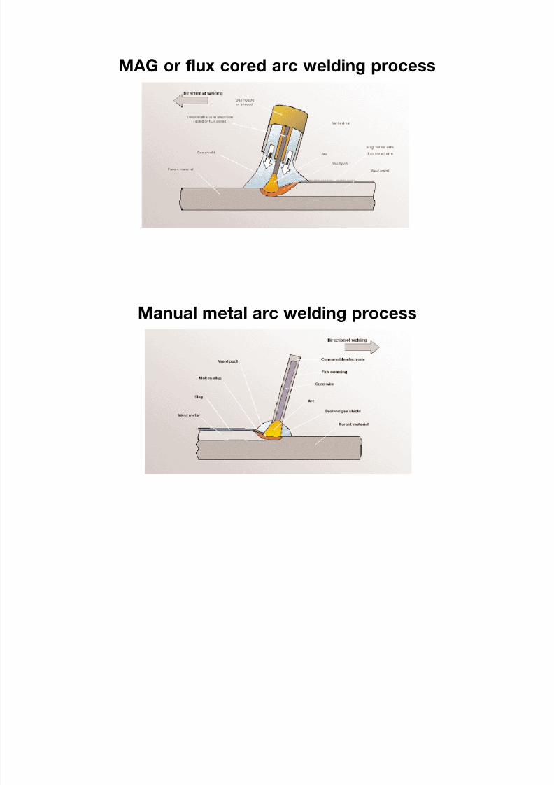
8/7/2019 52512003 Steel Bridges
http://slidepdf.com/reader/full/52512003-steel-bridges 60/96
MAG or flux cored arc welding process
Manual metal arc welding process

8/7/2019 52512003 Steel Bridges
http://slidepdf.com/reader/full/52512003-steel-bridges 61/96

8/7/2019 52512003 Steel Bridges
http://slidepdf.com/reader/full/52512003-steel-bridges 62/96
to be judged against the particular project
requirements of course; thus severe restriction of
construction depth will increase the weight of the
members, however efficient the design is.
In general more complex fabrication is more expensive,
especially if measured on a cost per tonne basis.
Fabrication is generally more economic if connections
are simple, geometry is straightforward, and theamount of welding is minimised. The complexity of a
design is the outcome of the designer's response to
the imposed constraints and the choices he makes:
thus for example, a viaduct may have to conform to
complex highway geometry but a decision to use
integral crossheads would compound the complexity
and cost of fabrication and erection substantially.
Modern CAD systems and CNC fabrication equipment
can well accommodate such complex geometry to
ease the drawing and production processes, but they
cannot eliminate all the extra costs in workmanship,
organisation and management. In detailing, every
additional component, every extra weld adds to thecost so it pays the designer to consider the options
and anticipate relative costs in making his choices.
The buildability of structural steelwork is a cost issue
as well as a safety issue for the designer; indeed
fulfilment of his obligations under CDM to reduce
exposure to hazards should contribute to overall
economy. Design for function and purpose has to
anticipate the fabrication and erection processes.
Good detailing is the first key to ensuring buildability –
say in the fabrication of box girders to minimise
hazardous and expensive internal activities, or in
ensuring that bolts can be entered and readilytightened in site connections. And, secondly, for
construction work on site the structural layout,
member sizing, and connections need to be consistent
with a practicable economic erection method: site
constraints on time, say for rail or road closures, and
physical restrictions on access, crane position,
temporary supports and the like will determine what
that method will be. Connections should be detailed to
facilitate site fitting with some rotational and
dimensional tolerance, bearing in mind the factors of
camber prediction and fabrication tolerances: this is
important for safety and cost, and can be met readily
with bolted joints. In some circumstances extrastiffening or strength will need to be designed in to the
members, say for launching or a big lift, and that will be
less costly if done at the outset. The level of erection
costs is determined by the potential difficulty of the site
and the project constraints; the designer has real
scope to increase or reduce that cost.
To achieve good quality design which satisfies all the
criteria is not easy; it requires skill in the use of steel at
the concept and detail stages of design. Some
designers are more experienced in steel bridge design
than others: greater experience should lead to simpler
and more economic design which will reducetotal costs.
7.2.4 Specification
The project specification is an essential part of the
design, and it is germane to what has to be paid for.
The project specification should express clearly what
the designer requires, be up to date and refer to
current national and international standards.
Conformance with well recognised specifications for
fabrication and erection (eg based on BS 5400: Part 6)
will reduce uncertainty and help to minimise cost;
specifiers should avoid introducing personalised
clauses demanding, say, extra fabrication tolerances,
testing procedures, or architectural finishes as these
will increase fabrication costs. Some projects will
require special clauses to meet particular needs, but
these should reflect recognised good practice and not
over-anticipate problems. The SCI publication "Model
Appendix 18/1" (Specification of Structural Steelwork
for Bridges) contains a series of model clauses which
may be inserted into a project specification and which
is compatible with the Specification for Highway
Works, BS 5400 Part 6, and associated standards. In
the limit, any tendency towards "preferential
engineering" adds to the cost and price of a steel
bridge.
7.2.5 Programme
The project programme should reflect an informed
view of achieving the client's objective consistent with
allowing sufficient time to complete all the necessary
tasks – administrative, intellectual, and practical, at site
and elsewhere – within the logical constraints of the
design and other project requirements. Within thatprogramme, the steelwork contractor needs sufficient
time to do all that he has to do – many activities are in
his direct control, others such as supply of steel are
not. For most bridge steelwork the time required to
complete the work most economically can be reduced
by special measures, or taking risks, but such
measures come at a price. Therefore it is important not
to compress the steelwork programme below the
allowance of sufficient time for economy, without
recognising the enhanced cost and risk to the project.
This is discussed in more detail in section 7.3. Typical
fabrication periods range from four weeks from receiptof steel for small simple structures through to many
months for large complex structures: the necessary
period depends on the capacity of the factory and its
workload too.
Within the detail of the project programme features
which tend to increase the site cost of the
steelwork are
- time constraints on deliveries and hours of working
- phasing of erection requiring more that one visit to
site
- possession work requiring multi-shift and night work
54
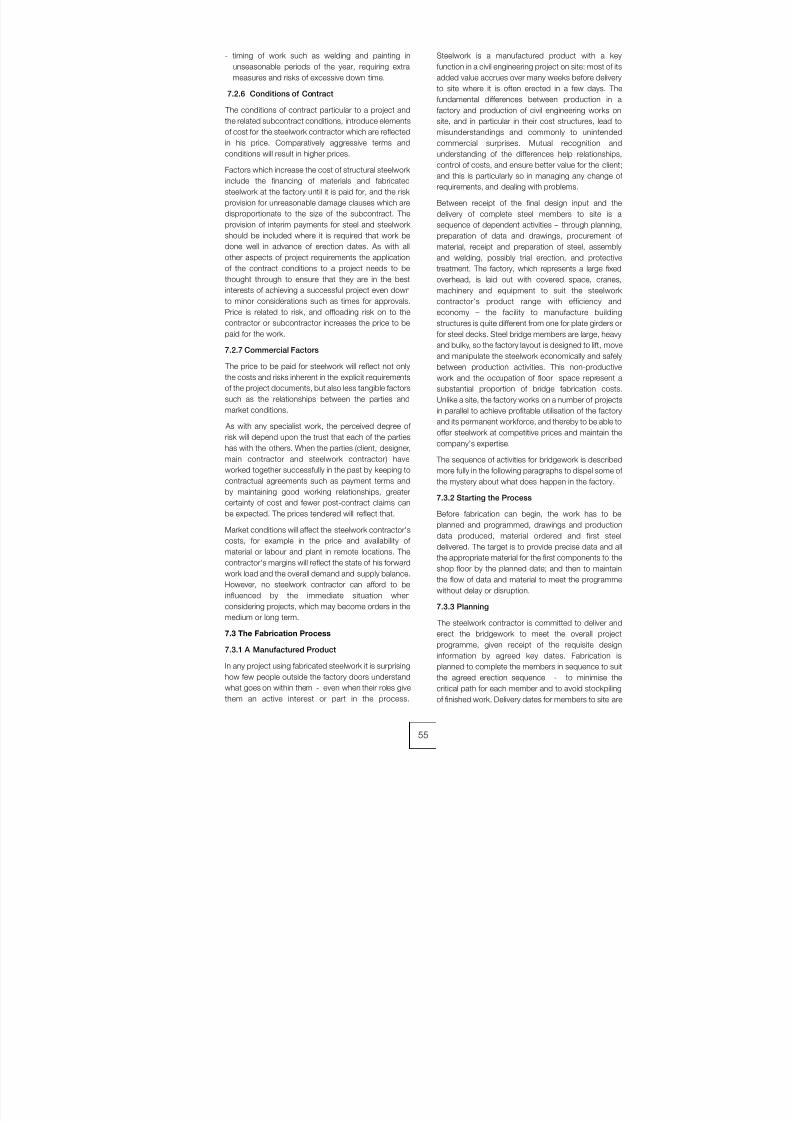
8/7/2019 52512003 Steel Bridges
http://slidepdf.com/reader/full/52512003-steel-bridges 63/96
- timing of work such as welding and painting in
unseasonable periods of the year, requiring extra
measures and risks of excessive down time.
7.2.6 Conditions of Contract
The conditions of contract particular to a project and
the related subcontract conditions, introduce elements
of cost for the steelwork contractor which are reflected
in his price. Comparatively aggressive terms and
conditions will result in higher prices.
Factors which increase the cost of structural steelwork
include the financing of materials and fabricated
steelwork at the factory until it is paid for, and the risk
provision for unreasonable damage clauses which are
disproportionate to the size of the subcontract. The
provision of interim payments for steel and steelwork
should be included where it is required that work be
done well in advance of erection dates. As with all
other aspects of project requirements the application
of the contract conditions to a project needs to be
thought through to ensure that they are in the best
interests of achieving a successful project even down
to minor considerations such as times for approvals.
Price is related to risk, and offloading risk on to the
contractor or subcontractor increases the price to be
paid for the work.
7.2.7 Commercial Factors
The price to be paid for steelwork will reflect not only
the costs and risks inherent in the explicit requirements
of the project documents, but also less tangible factors
such as the relationships between the parties and
market conditions.
As with any specialist work, the perceived degree of
risk will depend upon the trust that each of the parties
has with the others. When the parties (client, designer,
main contractor and steelwork contractor) have
worked together successfully in the past by keeping to
contractual agreements such as payment terms and
by maintaining good working relationships, greater
certainty of cost and fewer post-contract claims can
be expected. The prices tendered will reflect that.
Market conditions will affect the steelwork contractor's
costs, for example in the price and availability of
material or labour and plant in remote locations. Thecontractor's margins will reflect the state of his forward
work load and the overall demand and supply balance.
However, no steelwork contractor can afford to be
influenced by the immediate situation when
considering projects, which may become orders in the
medium or long term.
7.3 The Fabrication Process
7.3.1 A Manufactured Product
In any project using fabricated steelwork it is surprising
how few people outside the factory doors understand
what goes on within them - even when their roles give
them an active interest or part in the process.
Steelwork is a manufactured product with a key
function in a civil engineering project on site: most of its
added value accrues over many weeks before delivery
to site where it is often erected in a few days. The
fundamental differences between production in a
factory and production of civil engineering works on
site, and in particular in their cost structures, lead to
misunderstandings and commonly to unintended
commercial surprises. Mutual recognition and
understanding of the differences help relationships,
control of costs, and ensure better value for the client;
and this is particularly so in managing any change of
requirements, and dealing with problems.
Between receipt of the final design input and the
delivery of complete steel members to site is a
sequence of dependent activities – through planning,
preparation of data and drawings, procurement of
material, receipt and preparation of steel, assembly
and welding, possibly trial erection, and protective
treatment. The factory, which represents a large fixed
overhead, is laid out with covered space, cranes,
machinery and equipment to suit the steelwork
contractor's product range with efficiency and
economy – the facility to manufacture building
structures is quite different from one for plate girders or
for steel decks. Steel bridge members are large, heavy
and bulky, so the factory layout is designed to lift, move
and manipulate the steelwork economically and safely
between production activities. This non-productive
work and the occupation of floor space represent a
substantial proportion of bridge fabrication costs.
Unlike a site, the factory works on a number of projects
in parallel to achieve profitable utilisation of the factory
and its permanent workforce, and thereby to be able to
offer steelwork at competitive prices and maintain the
company's expertise.
The sequence of activities for bridgework is described
more fully in the following paragraphs to dispel some of
the mystery about what does happen in the factory.
7.3.2 Starting the Process
Before fabrication can begin, the work has to be
planned and programmed, drawings and production
data produced, material ordered and first steel
delivered. The target is to provide precise data and all
the appropriate material for the first components to the
shop floor by the planned date; and then to maintain
the flow of data and material to meet the programme
without delay or disruption.
7.3.3 Planning
The steelwork contractor is committed to deliver and
erect the bridgework to meet the overall project
programme, given receipt of the requisite design
information by agreed key dates. Fabrication is
planned to complete the members in sequence to suit
the agreed erection sequence - to minimise the
critical path for each member and to avoid stockpiling
of finished work. Delivery dates for members to site are
55

8/7/2019 52512003 Steel Bridges
http://slidepdf.com/reader/full/52512003-steel-bridges 64/96
determined by an erection programme with sufficient
duration to do the work safely and to specification
within all site constraints. Within the factory, efficient
use of the space, equipment, and the substantially
fixed level of resource requires the programme to fit
into the overall works programme to balance demand
and avoid bottlenecks. Work may be planned for sub-
letting for specialist operations, say bending or
machining, or to deal with overload.
Specialist planning is done, to meet the programme, in
preparing method statements for more complex
activities, inspection and test plans, risk assessments
for site work, erection method statements, and health
and safety plans - all within a company specific quality
management system.
Preparation of all this information, which is prerequisite
to doing the job properly, depends on timely and
sufficient accurate input from the other parties to the
project, and timely response to submissions requiring
approval.
Erection planning will include a measure of
construction engineering, dependent on the scale and
complexity of the bridgeworks, including structural
analysis, temporary works design and independent
checks. This in turn requires full information from the
site and agreement between the parties on method,
timing and responsibilities before it can be completed.
7.3.4 Drawings and Production Data
The design input has to be processed to schedule
material for procurement, to generate work instructions
for tradesmen or machines on the factory floor, and forconstruction engineering at site. With progressive
automation of fabrication, the industry is moving
towards making fabrication drawings obsolescent –
the design data are converted directly into digital
instructions for machines. Each steelwork contractor
will format the data to suit his particular factory facility
and such fabrication drawings as are made, are for his
purposes in fabrication and erection of the bridgework.
To implement the design of the steelwork efficiently
and in a timely manner, it is vital that the design input
expresses the designer's intent clearly and completely
at the outset and certainly before the commencement
of CAD detailing or modelling: typically this information
is required between four and six weeks before
fabrication starts. Where members are required to be
cambered the designer should provide the data on the
design drawings, which can come from his computer
model; it is not cost effective for the steelwork
contractor to set up a new model and make his
calculations on the critical path of his work - adding
time, cost, and risk of delay.
7.3.5 Material Procurement
Steelwork contractors do not carry stocks of material,
except a basic minimum for projects in progress, somaterial is bought specifically for each new project. For
most bridges, costs can be minimised by ordering
plates and sections directly from the steel mills, in
contrast to the UK market for building steelwork, which
depends much more on steel stockholders. Some
bridge materials, including most special grades such
as S460 or WR steels and larger sizes of section, are
not available from stockholders at any price. Time has
to be allowed in any bridge procurement programmefor supply from the mills with typical lead times of six to
twelve weeks for plate and between six and sixteen
weeks for larger sections and tubes. Full design
information is not necessary to enable orders for steel
to be placed but sufficient detail must be available to
define all components in advance of rolling dates to
minimise waste and costs.
For members fabricated from plate, most plate
components including flanges, webs and stiffeners,
are cut from plates of economic size and width. Hence
steel listing for ordering includes a computerised
nesting process to achieve best utilisation andminimise waste to no more than a few percent. To the
same end, the designer should avoid mixing of grades
where possible and rationalise the range of plate
thicknesses and section sizes. Advice is given in
Chapters 1 and 2 on plate sizes and the availability of
steel grades.
7.3.6 Receipt of Material
As material is received at the factory it is marshalled for
transfer into the preparation area in the programmed
sequence. Usually as the steel is picked up it receives
pre-fabrication cleaning by grit-blasting to remove all
mill-scale, rust and dirt. This provides clean surfaces
for marking and welding and reveals any superficial
defects in the material, should there be any, before
work starts.
7.3.7 Preparation
This term is used to cover the set of operations which
converts the plain material into finished plate or section
components ready for assembly and welding. The
range of processes and equipment used depends on
the requirement for each component: it includes
marking, cutting, edge preparation, drilling, pressing
and machining: sections may be processed through
automated saw and drill lines for cutting and drilling.
7.3.8 Marking
The day of the large template loft with string line and
plywood is long gone, to be replaced by desktop PC.
Some steelwork contractors have automated the
process, but it still has a major cost which can be
minimised by keeping the structure design simple. For
example, complex arrangements of shear studs are
inevitably more expensive than simple arrangements
which can utilise templates for marking and are easy to
check – ensuring that there are no fouls withreinforcing bars at site.
56
8/7/2019 52512003 Steel Bridges
http://slidepdf.com/reader/full/52512003-steel-bridges 65/96
7.3.9 Cutting
Components for box and plate girders will usually be
cut from plate by plasma or oxy-propane equipment
mounted on CNC machines. These closely controlled
techniques are generally accurate and efficiency is
dependent largely on the process. It is possible to
increase cutting costs by adding complexity; for
example, creating too many types of stiffener preventsmulti-head profiling. As plates are cut up, each piece is
marked for identification and material traceability.
Other components such as bracings should be
detailed for simplicity with the aim of minimising the
number of pieces to cut. Ends of bracings should be
cut square rather than mitred and single members
should be used in preference to back-to-back
members.
7.3.10 Preparation of Edges
Unnecessary preparation of edges should be avoided.
The hardness of flame cut edges can be controlledquite simply through qualified cutting procedures so
that grinding of edges is not necessary. Fillet welds
rather than penetration welds should be used where
possible, for the same reason. The costly practice of
grinding arrises to a prescribed radius, of 3mm say, to
avoid edge defects in protective treatment is no longer
necessary with the high solids chemical cure paint
systems used today.
Machining of edges should not be specified unless
proven to be absolutely essential to achieve the
welded connection – for example in achieving partial
penetration welds for deck stiffeners with highpenetration without blowthrough.
7.3.11 Drilling
Usually all holes for site-bolted connections are drilled
in the factory, and for welded members most holes are
drilled in preparation before assembly using CNC
machines. Drilling holes in large assembled members
is more costly because less efficient portable machines
have to be mounted on the member. For complex
assemblies final holes may have to be drilled in trial
assembly with the joint material to ensure a good
match at site. Small components, particularly splice
plates, are drilled in packs so simple detail and
repetition contribute to cost reduction.
7.3.12 Pressing
Bridge steelwork contractors and specialist workshops
are equipped with a variety of presses which may be
used to form members from plate, or for remedial
working of deformed components. Designers are
advised to seek specialist advice before using cold
formed details in design. The details need to suit the
available equipment and the specification for the
relevant material may need modifying. The introduction
of plate bending adds an activity, which the steelworkcontractor may have to sublet, so time and cost effects
need to be considered.
7.3.13 Assembly
The fabrication process is arranged so that work on
each principal member is a continuous process with
the minimum standing time. Thus the set of
components for a member is prepared as a batch and
moved on to the assembly area or machines withoutdelay to be put together and welded, for such non-
productive time has a cost.
The assembly of plate girders and box girders is
described in some detail in Chapter 3. Methods vary
between steelwork contractors for similar products:
each one chooses the most efficient and economic
way of using the factory's equipment and space -
some with large capital investment and fewer
manhours, some with modest facilities and much
greater skilled manhours. The same volume of welding
is undertaken, the same issues of accuracy and
distortion have to be controlled.
Welding procedure and processes are described in
detail in Chapter 6. There are two main factors that
affect welding costs, the choice of process and the
efficiency of application of that process. Higher
deposition processes such as submerged arc welding
(SAW) can reduce welding costs, but they are limited
by gravity and are intolerant of damp steel or
consumables, so they are not practical for most site
welding. High deposition processes, mounted on
automatic or semi-automatic machines are used
whenever possible in shop assembly, normally utilising
metal active gas (MAG) techniques which are most
common in UK steelwork contractors. Manual metal
arc welding (MMA), commonly called 'stick' welding, is
far less efficient, but can be the only choice for
complex joints and details - a choice which is
imposed by the complexity of design and where details
have not taken account of how welds can be made.
Generally the route to minimum cost of welding in the
UK is to maximise the use of automated equipment in
the fabrication works and minimise welding on site.
Grinding of butt welds in members requires another
operation on the critical path of fabrication which is
hazardous, time consuming and relatively costly for the
perceived benefit. The vibration effects of the tools are
hazardous and so their use is now strictly regulated to
protect the operator. Consideration should be given to
the need to grind flush particularly for longitudinal butt
welds, where welds can be completed with a neat
profile, and especially on internal surfaces.
As described earlier the cost of lifting and turning large
assemblies to facilitate welding, particularly of box
girders, can be reduced by careful design of the
connections of webs and flanges. Similarly, hazardous
and high cost work in the interior of box girders is verydependent on the thought given to internal detail.
57

8/7/2019 52512003 Steel Bridges
http://slidepdf.com/reader/full/52512003-steel-bridges 66/96
Some types of bridge require members to be
machined after completion of assembly and welding,
for example the members of an arch or at connections
for suspension systems on major bridges. Steelwork
contractors have limited capability for in house
machining, so subletting to specialists at high cost or
using portable machines with limited cutting capacity
are options. Designers should seek to avoid machineryat this stage of production unless there is very good
cause.
Trial erection has been discussed elsewhere, but it is
worth mentioning in a discussion of cost as it has a
major impact on the length of the fabrication
programme: a member required in trial erection cannot
be released for painting and delivery to site until the last
member is fabricated and the trial assembly is checked
and released. Generally the considerable cost of
manhours, craneage, and space in the works is non-
productive save for the assurance of minimising risk of
delay at site. Given the accuracy of modern fabrication
machinery and the variety of techniques available to
the steelwork contractor to demonstrate that the fit will
be achieved, trial erection is to be avoided.
As assembly of members progresses inspection, NDT
and mechanical testing are carried out to minimise
delay to release of the completed members.
7.3.14 Managing Change
Fabrication is a continuous programme of activities
from receipt of first information to completion and
delivery of the finished member. The specification andother contract requirements require reference at
various stages to the designer, the Engineer, and other
parties - they have a part to play in the process, and
how they fulfil their roles bears on the steelwork
contractor's performance.
Few projects reach their conclusion without the need
for change, stemming from any of the parties and
impacting on the others. The cost effects of change
which impact on fabrication become more severe the
later they occur in the fabrication programme: even
apparently quite modest changes can have substantial
time and cost consequences, for they not only put the
project fabrication at risk, but they can disrupt work on
other projects in the factory at the same time.
Experienced steelwork contractors make prudent
assessments of the risks of delays in information,
approvals and consents, and develop contingency
plans to deal with problems. To the extent that
technical factors are involved, it is important that
designers and supervising engineers develop good
working relationships and effective channels of
communication with the steelwork contractors; mutual
understanding can make a great difference to the costof the project and its success.
7.4 Protective Treatment
Conventional practice requires the completed steel
members to be blast cleaned, perhaps metal sprayed,
and part painted before delivery to site; finish coats are
applied after the bridge is built. The steelwork
contractor carries out the first stage at the fabrication
works, given the capital investment in proper blasting
and painting facilities, or en route to the site at a sub-contractor's facility which incurs extra handling and
transport costs. Very bulky bridge members take up
considerable space in the facility so each one is blast-
cleaned and painted as quickly as possible, whilst
maintaining intercoat times, to maximise throughput of
the plant.
Although protective treatment of bridge steelwork is
largely outside the scope of this book, the way it is
organised within the project programme - when,
where and how - does affect the overall cost of the
bridge. Commonly, project specifications will constrain
the application of the protective treatment withoutregard to the construction of the bridge; and
sometimes the work can thereby be more expensive
and protection be impaired. It is well worth reviewing
the application requirements for each project to ensure
best value.
The primary function of protective treatment is just that
– to protect the steel from corrosion for as long as can
be achieved with the chosen technology: the
appearance of the finished bridge is not unimportant,
but it should take second place to protection in the
specifier's mind. Performance of the treatment
depends on four fundamental factors
– design to avoid vulnerable details,
– very effective surface preparation,
– selection of an appropriate system, and
– application of the system within the manufacturer's
criteria
Of these, the surface preparation and the application
require suitable ambient conditions, which are best
achieved in an indoor and preferably controlled
environment. Dust and dirt, high humidity, low
temperature and poor access all aggravate the risks of premature failure and reduced life before first
maintenance.
Site conditions generally militate against good
application standards, and the processes can have
severe environmental impact. For example:
- the essential ambient temperature and humidity
criteria are very difficult to meet in wet or cold
weather; so the winter months in the UK are virtually
a close season for site painting;
- exclusion of dust and dirt from the process, and
between coats on a civil construction site ischallenging;
58
8/7/2019 52512003 Steel Bridges
http://slidepdf.com/reader/full/52512003-steel-bridges 67/96
- access to erected bridgework for safe treatment
has a high cost, as does shielding of the process
and the environment;
- site welded joints require blast-cleaning which is a
very dirty process and a threat to the site
environment;
- painting bridges over live highways or rail track in
possessions, and at night, puts quality at risk.
Thus it is beneficial to the performance of the finished
system and value to minimise protective treatment at
site, and to eliminate it if practicable. The example of
the Foyle Bridge, where less than 1% of a 508m long
box girder bridge was painted at site, may be difficult
to emulate but the potential benefits are substantial –
directly and indirectly too in simplifying work overall on
site. The practice of fully painting girders, sometimes in
complete braced pairs, is increasing: certainly there
seems to be a good case for leaving just the
connections to be painted at site, and applying finish
coat on the few surfaces that impact on the overall
appearance of the bridge.
Damage to painted surfaces in transit, and during
erection and construction of deck slabs is a very real
problem, but with properly planned and managed
systems of work should not be a major issue. Even
when it does occur, the remedial measures should
cost far less than full painting on site. Risk of damage
during construction is not just a consideration for the
steelwork contractor, but also for the designer and for
the main contractor in detailing and construction of the
substructures and composite decks.
In brief, as with most aspects of the bridge, the
application of the protective treatment needs to be
thought through by the designer in designing and
specifying the work as part of seeking best value for
the client.
7.5 Erection
The painted fabricated steelwork is delivered to site in
sequence to meet the planned erection method and
programme. For major roadworks projects steel
erection is phased to suit the construction of
roadworks; generally for railway bridges it will be
organised around the key track possession dates.
The discussion of erection in Chapter 1 illustrates the
variety of methods used with today's plant and
equipment. Each new bridge presents a unique
erection problem. The solution has to match the
determining factors for that bridge on that site; so
notionally identical structures on two different sites
could well require different erection methods with quite
unrelated levels of cost. Erection costs are determined
fundamentally by the method to be used; so to
estimate the cost, the steelwork contractor works up a
method and then calculates the requirements for time,
resources, temporary works, and engineering.
The erection of the bridge is an opportunity for the
bridge-builder to use his ingenuity and experience to
contribute to the best value of the project: he will do
that to help the steelwork contractor to produce the
most competitive tender and successful job. Bridge
layout, configuration and details can help or hinder
efficient safe erection so in an ideal world the designer
would anticipate the optimum erection method: a
principal benefit of design and construct projects is
that design for function and service can go hand-in-
hand with design for construction.
As discussed in Chapter 1 the designer has to make
assumptions about sequence to complete his analysis
and design, and to satisfy himself that the bridge can
be built in a safe and practicable manner to fulfil his
CDM obligations. It is quite possible that the
contractor, who is responsible for the method which is
used, will propose a different method: this may require
the designer to revisit the design, but any cost to the
client in doing that should be measured against the
benefits of the more competitive offer. Clearly the
steelwork contractor has to satisfy himself and the
designer that the proposed method is structurally
viable and safe.
Whatever the method, the steelwork contractor will
submit method statements, temporary works designs
and, when required, independent check certificates for
approvals. It is not uncommon for the vagaries of
construction, particularly of major roadworks, to
prevent final details and documentation of schemes to
be complete until shortly before the work is to be done.
Again, good channels for technical communication
between the parties are essential for safe efficientoperations.
7.6 Guidance on Cost
7.6.1 What is a useful measure of cost?
Some believe that they can use a simple measure such
as 'rate per tonne' to evaluate schemes; perhaps that
view is encouraged by such in the common methods
of measurement and bills of quantities. This is not
effective and can be misleading because only a small
percentage of the overall cost of steelwork can be
related simply to tonnage - in fabrication or erection.
Even for the basic steel material cost there is not asimple 'rate per tonne', with many factors such as the
grade, source, section size, plate length, plate width,
test requirements and quantity all having a significant
effect on the price of the material from the mills - and
before such factors as wastage are taken into account.
Many erection costs, say for temporary works or hire of
a crane, are virtually independent of the tonnage. This
in itself raises commercial difficulties in evaluating
changes for bridge steelwork through a bill of
quantities at contract stage.
Almost all of the cost of bridge steelwork is influenced
directly by the detail of the design and the
configuration of the structure on the site which are of
59
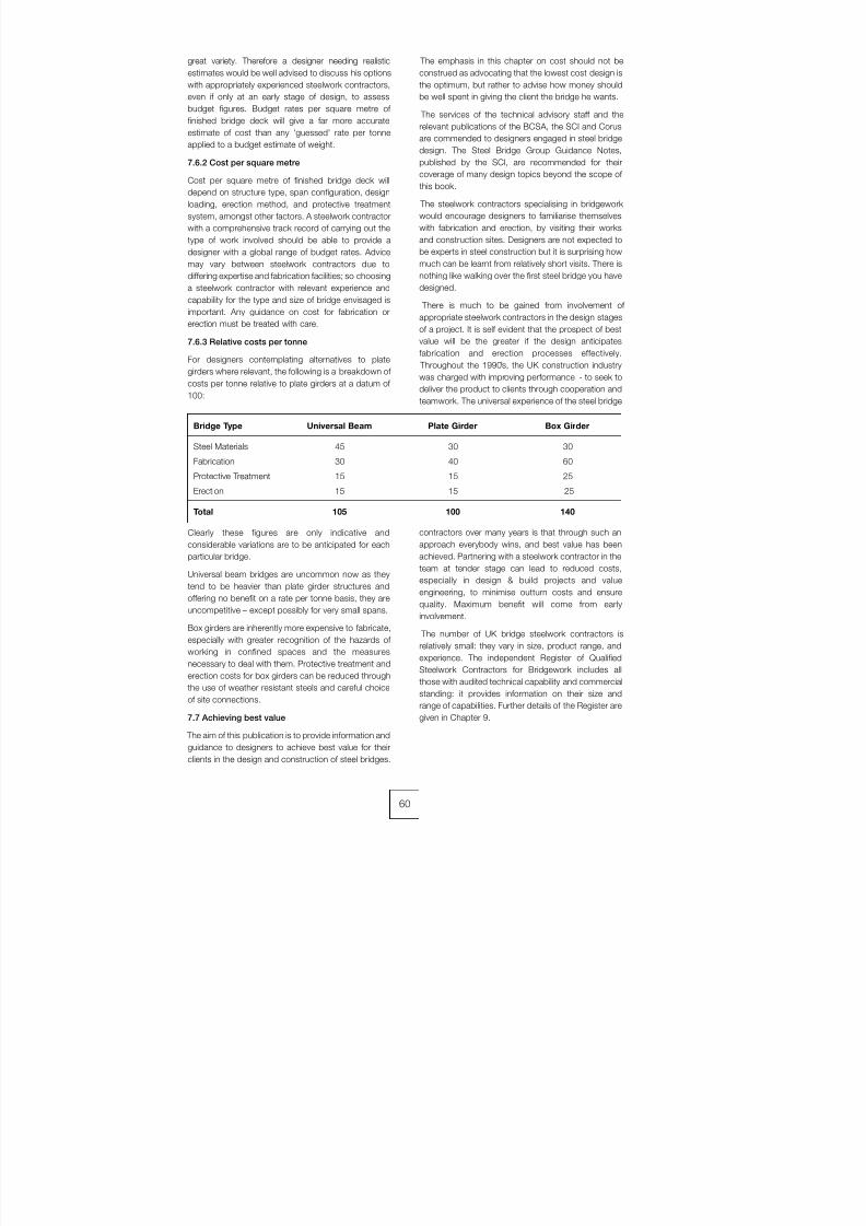
8/7/2019 52512003 Steel Bridges
http://slidepdf.com/reader/full/52512003-steel-bridges 68/96
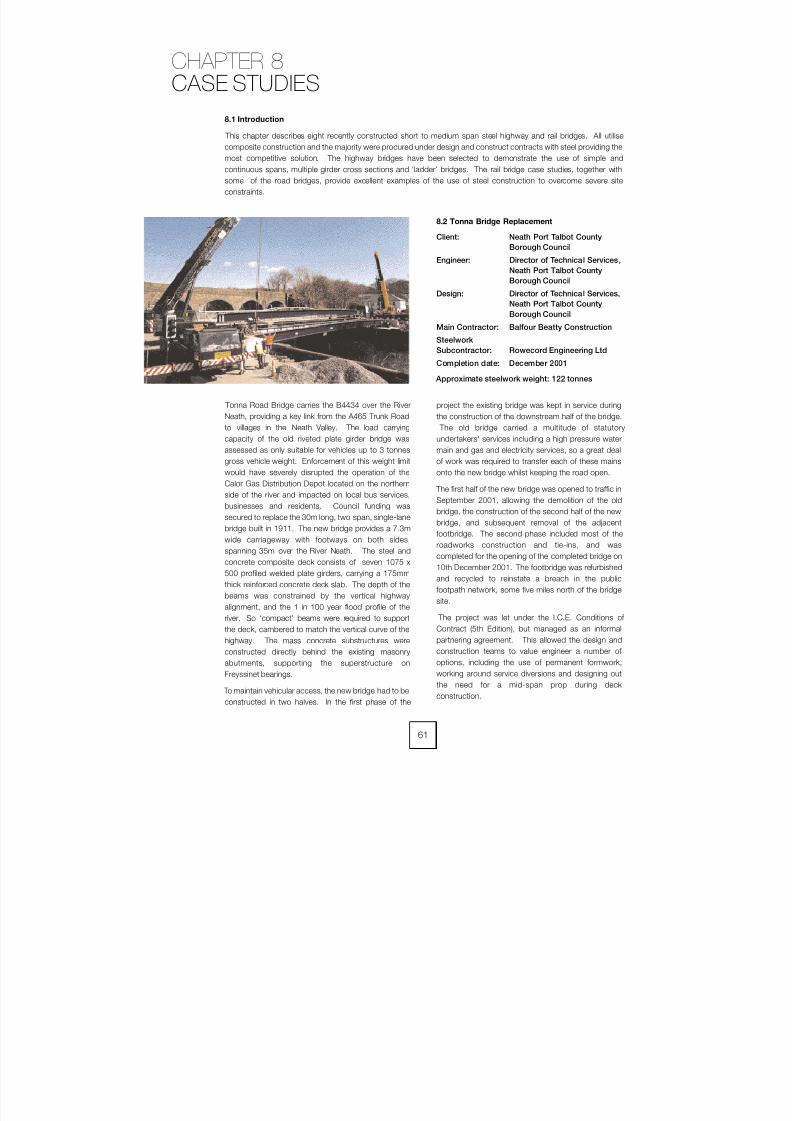
8/7/2019 52512003 Steel Bridges
http://slidepdf.com/reader/full/52512003-steel-bridges 69/96
8.2 Tonna Bridge Replacement
Client: Neath Port Talbot County
Borough Council
Engineer: Director of Technical Services,
Neath Port Talbot County
Borough Council
Design: Director of Technical Services,
Neath Port Talbot County
Borough Council
Main Contractor: Balfour Beatty Construction
Steelwork
Subcontractor: Rowecord Engineering Ltd
Completion date: December 2001
Approximate steelwork weight: 122 tonnes
Tonna Road Bridge carries the B4434 over the River
Neath, providing a key link from the A465 Trunk Roadto villages in the Neath Valley. The load carrying
capacity of the old riveted plate girder bridge was
assessed as only suitable for vehicles up to 3 tonnes
gross vehicle weight. Enforcement of this weight limit
would have severely disrupted the operation of the
Calor Gas Distribution Depot located on the northern
side of the river and impacted on local bus services,
businesses and residents. Council funding was
secured to replace the 30m long, two span, single-lane
bridge built in 1911. The new bridge provides a 7.3m
wide carriageway with footways on both sides,
spanning 35m over the River Neath. The steel andconcrete composite deck consists of seven 1075 x
500 profiled welded plate girders, carrying a 175mm
thick reinforced concrete deck slab. The depth of the
beams was constrained by the vertical highway
alignment, and the 1 in 100 year flood profile of the
river. So ‘compact’ beams were required to support
the deck, cambered to match the vertical curve of the
highway. The mass concrete substructures were
constructed directly behind the existing masonry
abutments, supporting the superstructure on
Freyssinet bearings.
To maintain vehicular access, the new bridge had to beconstructed in two halves. In the first phase of the
project the existing bridge was kept in service during
the construction of the downstream half of the bridge. The old bridge carried a multitude of statutory
undertakers' services including a high pressure water
main and gas and electricity services, so a great deal
of work was required to transfer each of these mains
onto the new bridge whilst keeping the road open.
The first half of the new bridge was opened to traffic in
September 2001, allowing the demolition of the old
bridge, the construction of the second half of the new
bridge, and subsequent removal of the adjacent
footbridge. The second phase included most of the
roadworks construction and tie-ins, and was
completed for the opening of the completed bridge on
10th December 2001. The footbridge was refurbished
and recycled to reinstate a breach in the public
footpath network, some five miles north of the bridge
site.
The project was let under the I.C.E. Conditions of
Contract (5th Edition), but managed as an informal
partnering agreement. This allowed the design and
construction teams to value engineer a number of
options, including the use of permanent formwork,
working around service diversions and designing out
the need for a mid-span prop during deck
construction.
8.1 Introduction
This chapter describes eight recently constructed short to medium span steel highway and rail bridges. All utilisecomposite construction and the majority were procured under design and construct contracts with steel providing the
most competitive solution. The highway bridges have been selected to demonstrate the use of simple and
continuous spans, multiple girder cross sections and ‘ladder’ bridges. The rail bridge case studies, together with
some of the road bridges, provide excellent examples of the use of steel construction to overcome severe site
constraints.
61
CHAPTER 8
CASE STUDIES
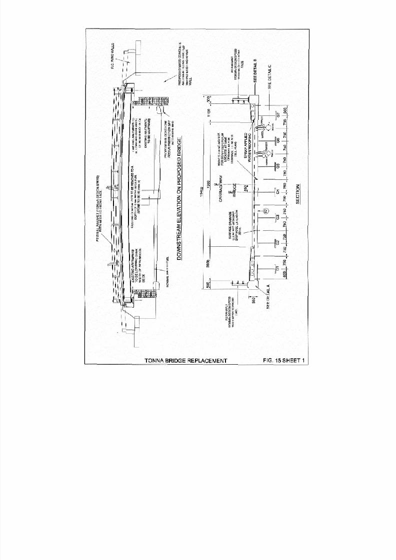
8/7/2019 52512003 Steel Bridges
http://slidepdf.com/reader/full/52512003-steel-bridges 70/96
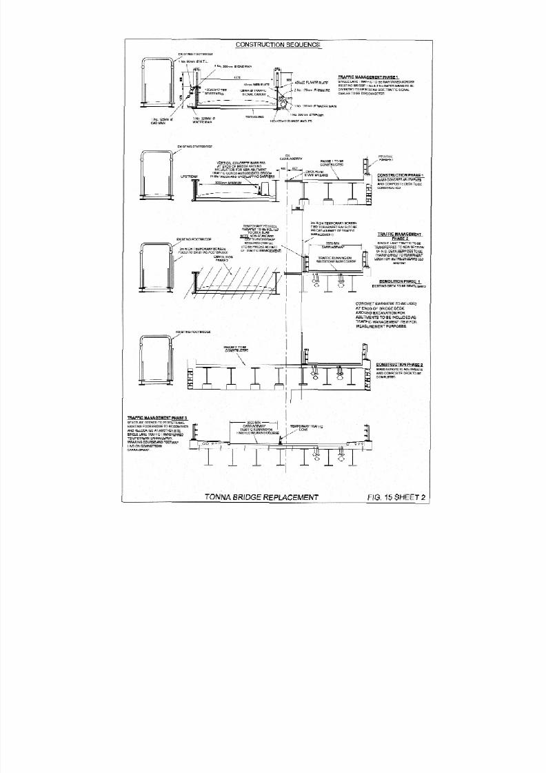
8/7/2019 52512003 Steel Bridges
http://slidepdf.com/reader/full/52512003-steel-bridges 71/96

8/7/2019 52512003 Steel Bridges
http://slidepdf.com/reader/full/52512003-steel-bridges 72/96
64
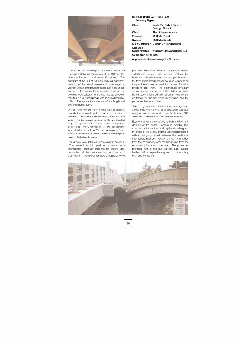
8/7/2019 52512003 Steel Bridges
http://slidepdf.com/reader/full/52512003-steel-bridges 73/96
8.3 Road Bridge A34 Trunk Road –
Newbury Bypass
Client: Neath Port Talbot County
Borough Council
Client: The Highways Agency
Engineer: Mott MacDonald
Design: Mott MacDonald
Main Contractor: Costain Civil Engineering
Steelwork
Subcontractor: Kvaerner Cleveland Bridge Ltd
Completion date: 1998
Approximate steelwork weight: 460 tonnes
This 11.3m wide Donnington Link Bridge carries the
previous northbound carriageway of the A34 over the
Newbury Bypass at a skew of 66 degrees. The
curvature of the A34 at this point required significant
widening of the central reserve and inside verge forvisibility, affecting the positioning and size of the bridge
supports. To minimise these increases single circular
columns were selected for the intermediate supports
resulting in a four span bridge with an overall length of
157m. The two centre spans are 40m in length and
two end spans 33.5m.
A deck with twin steel box girders was selected to
provide the torsional rigidity required by the single
columns. Twin boxes were chosen as opposed to a
wider single box to ease transport to site, and inverted
"top hat" girders with an insitu concrete top slab
selected to simplify fabrication. All site connectionswere detailed for bolting. The use of single column
piers avoided the visual conflict that multi-column piers
have on high skew bridges.
The girders were delivered to site singly in sections.
They were lifted into position by crane on to
intermediate temporary supports for splicing and
connection at the permanent supports by solid
diaphragms. Additional temporary supports were
provided under outer webs at the piers to provide
stability until the deck slab had been cast and the
boxes had achieved their torsional strength: these took
the form of reinforced concrete columns supported on
the pier bases using formwork for the pier of anotherbridge to cast them. The intermediate temporary
supports were removed once the girders had been
bolted together longitudinally, joined at the piers and
abutments by the transverse diaphragms, and the
permanent bearings grouted.
The box girders and the transverse diaphragms act
compositely with the insitu deck slab, which was cast
using permanent formwork within the boxes. GKN
"Paraslim" formwork was used for the cantilevers.
Ease of maintenance was given a high priority in the
detailing of the bridge. Access is available from
chambers at the abutments along the whole length of
the inside of the boxes, and through the diaphragms,
with crossings provided between the girders at
intermediate positions. Positive drainage is provided
from the carriageway over the bridge and from the
expansion joints should they leak. The girders are
protected with a four-coat external paint system
finished with a polyurethane gloss to provide a long
maintenance-free life.
65
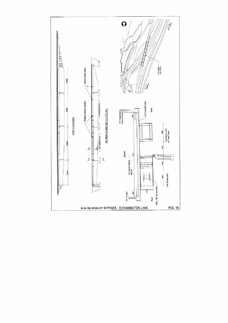
8/7/2019 52512003 Steel Bridges
http://slidepdf.com/reader/full/52512003-steel-bridges 74/96

8/7/2019 52512003 Steel Bridges
http://slidepdf.com/reader/full/52512003-steel-bridges 75/96
67
8.4 Westgate Bridges Deck Replacement
Client: Gloucestershire County Council
Engineer: Halcrow Group Ltd
Contractor: John Mowlem & Company plc
Steelwork
Subcontractor: Fairfield-Mabey Ltd
Completion date: June 2000
Approximate steelwork weight: 590 tonnes
The Westgate Bridges provide a strategic access to
Gloucester City from the West. The original bridges
were constructed in 1972 and comprised two identical
92m post tensioned concrete bridges with precast
pre-tensioned concrete suspended spans. Each
bridge carries one carriageway of the dual A417 over
the Eastern Arm of the River Severn at Gloucester.
Deterioration of the prestressed concrete was so
severe that a 3 tonne weight limit was imposed and
prevented gridlock of the roads in Gloucester. Bridge
deck replacement was compared with repair options
including works to the halving joints and replacementof the concrete span with a lightweight structure.
‘Whole Life Costing’ techniques confirmed that repairs
were not financially viable and the bridge deck would
need to be replaced.
Replacement of the superstructure was governed
entirely by the site constraints and sensitive traffic flows
on roads and river. The site constraints included:
– extensive services throughout the site,
– site of archaeological interest,
– maintenance of waterway headroom,
– essential maintenance of peak hour traffic flows to
avoid gridlock,
– poor ground conditions,
– works located within flood plain,
– vehicular and pedestrian access to be maintained
through the site,
– residential and commercial properties adjacent to
site, and
– existing footbridge located between road bridges.
The superstructure type was chosen for ease of
construction and to minimise maintenance
requirements over the River Severn. The chosen
superstructure has two continuous three span
overbridges with fabricated girders in weathering steel
acting compositely with an in situ reinforced concrete
deck slab.
Close co-operation between the Designer and
Contractor produced an innovative method of
construction using a bridge slide to maintain two lanes
of traffic at peak hours in both directions throughout
the works and prevent gridlock of Gloucester. Valueengineering was encouraged throughout the project
and a number of significant changes were made to the
design. These included the retention of the existing
pile caps and the use of polystyrene backfill behind the
abutments.
To prevent gridlock and maintain two lanes of traffic the
first new superstructure was constructed between the
existing bridges. This with the existing South Bridge
would carry in and outbound traffic enabling demolition
and replacement of the North Bridge. Traffic would
then use the two new superstructures during
demolition of the South Bridge. During a weekendroad closure the new South Bridge was slid into its final
position. The bridge weighed approximately 2000
tonnes and took only four and a half hours to slide the
12m along PTFE stainless steel tracks into position.
The bridge was re-opened to traffic some 45 hours
after the road closure.
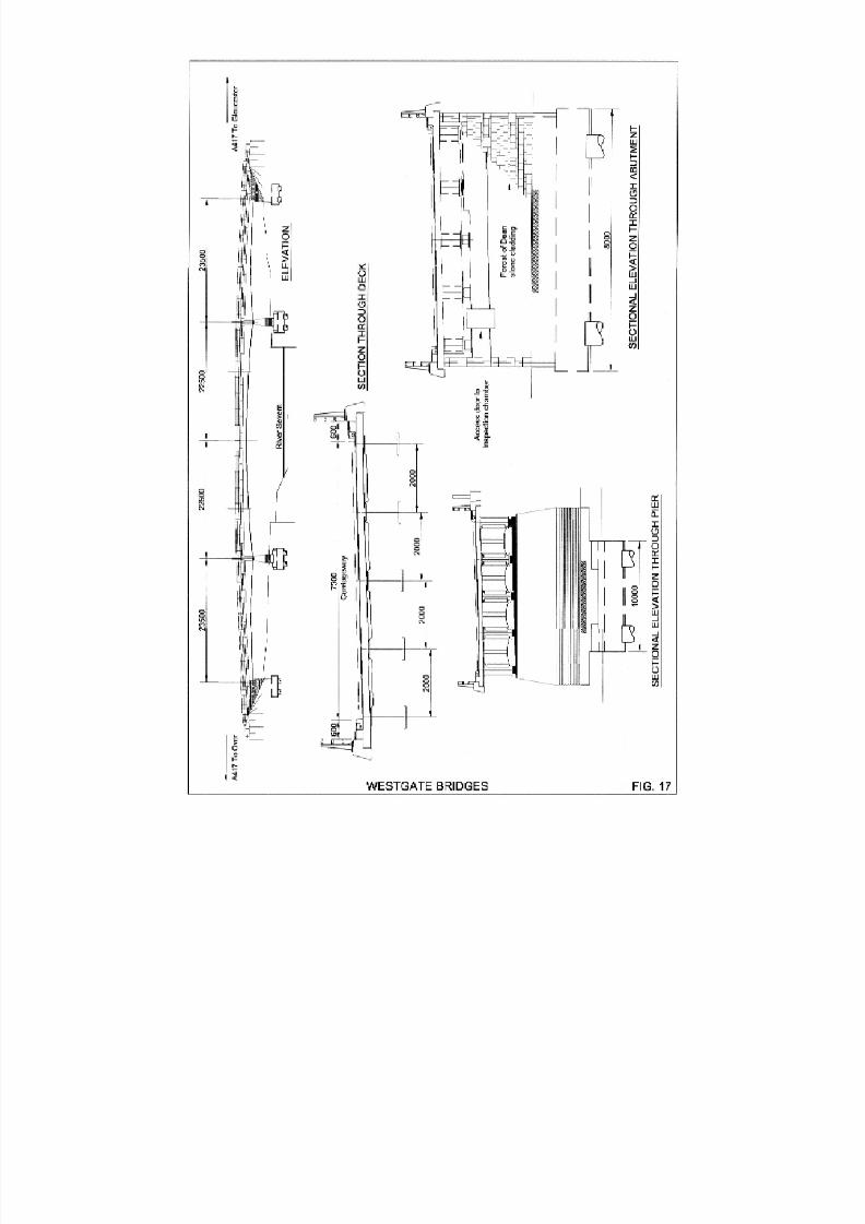
8/7/2019 52512003 Steel Bridges
http://slidepdf.com/reader/full/52512003-steel-bridges 76/96
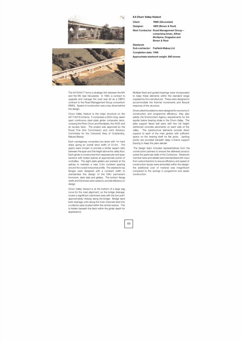
8/7/2019 52512003 Steel Bridges
http://slidepdf.com/reader/full/52512003-steel-bridges 77/96
69
8.5 Churn Valley Viaduct
Client: RMS (Gloucester)
Designer: KBR (Brown & Root)
Main Contractor: Road Management Group –
comprising Amec, Alfred
McAlpine, Dragados and
Brown & Root
Steelwork
Sub-contractor: Fairfield-Mabey Ltd
Completion date: 1998
Approximate steelwork weight: 890 tonnes
The A419/A417 forms a strategic link between the M4
and the M5 near Gloucester. In 1994, a contract to
upgrade and manage the road was let as a DBFO
contract to the Road Management Group consortium
(RMG). Speed of construction was a key driver behind
the design.
Churn Valley Viaduct is the major structure on the
A417/A419 scheme. It comprises a 250m long, seven
span continuous steel plate girder composite deck,
crossing the River Churn and floodplain, the A435 and
an access track. The project was approved by theRoyal Fine Arts Commission and Joint Advisory
Committee for the Cotswold Area of Outstanding
Natural Beauty.
Each carriageway comprises two lanes with 1m hard
strips giving an overall deck width of 22.5m. The
spans were chosen to provide a similar aspect ratio
between the span and the height above the valley floor.
Each girder is constructed from separate pier and span
sections with bolted splices at approximate points of
contraflex. The eight plate girders are cranked at the
splices to maintain a near 2.5m constant spacing
around the curved horizontal profile. The steelwork topflanges were designed with a constant width to
standardise the design of the EMJ permanent
formwork, deck slab and girders. The bottom flange
width and thickness were varied to provide efficiency in
design
Churn Valley Viaduct is at the bottom of a large sag
curve for the road alignment, so the bridge drainage
covers a significant catchment area with the low point
approximately midway along the bridge. Bridge deck
kerb drainage units along the inner channels feed into
a collector pipe located within the central reserve. This
is hidden beneath the deck within the girder depth for
appearance.
Multiple fixed and guided bearings were incorporated
to keep these elements within the standard range
supplied by the manufacturer. These were designed to
accommodate the thermal movements and flexural
response of the structure.
Driven piled foundations were designed for economy in
construction and programme efficiency; they also
satisfy the Environment Agency requirements for the
aquifer below bearing strata in the Churn Valley. The
piles support flared leaf piers with two full height
reinforced concrete abutments on each side of thevalley. The substructure elements provide direct
support to each of the main girders with sufficient
space on the bearing shelf for flat jacks. Jacking
points are provided beneath deep U-frame support
bracing to keep the piers slender.
The design team included representatives from the
construction partners to ensure the delivered product
suited the particular skills of the Contractor. Steelwork
member sizes and details were standardised with input
from subcontractors to ensure efficiency and speed of
construction issues were embodied within the design:
the additional cost of material was insignificantcompared to the savings in programme and easier
construction.
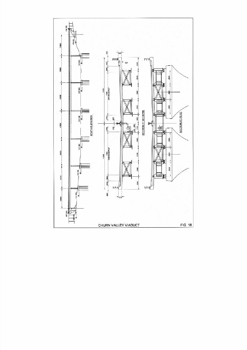
8/7/2019 52512003 Steel Bridges
http://slidepdf.com/reader/full/52512003-steel-bridges 78/96

8/7/2019 52512003 Steel Bridges
http://slidepdf.com/reader/full/52512003-steel-bridges 79/96
71
8.6 A500 Basford Hough Shavington Bypass,
London to Crewe Railway Bridge
Client: Highways Agency
Design: Babtie Group
Main Contractor: John Mowlem & Company plc
Steelwork
Subcontractor: Fairfield–Mabey LtdCompletion date: 2002
Approximate steelwork weight: 1270 tonnes
The bridge is located just south of Crewe and carries
the A500 over the four tracks of the west coast main
railway line and ten other tracks. All fourteen tracks are
electrified with overhead catenaries supported from
high gantries.
The bridge is 194m long, 22.6m wide with a skew of
23 degrees and consists of five continuous spans with
a maximum length of 54.5m. Each half of the deck
carries one carriageway and is supported on two main
longitudinal weathering steel girders 2.5m deep,
interconnected with skew transverse cross girders andbracing frames. The skew of the deck elements was
dictated by the layout of the piers and for ease of
launching. The deck slab of the bridge consists of
insitu lightweight concrete on permanent ribbed grp
formwork with precast concrete P6 parapets.
Each pier consists of a column under each bearing
position, linked at low level by reinforced concrete
walls. Pier size was dictated by the need to
accommodate permanent bearings, temporary launch
skates and jacks. Provision was also made for lateral
guide rollers and a "fail safe" concrete upstand to
prevent the girders falling sideways off the piers. Thesubstructures are supported on 600mm diameter CFA
piles to a maximum depth of 23m.
The deck was constructed in two halves on the
partially constructed east approach embankment and
launched longitudinally into position on the previously
constructed substructure. This avoided the need for
intricate staged erection between overhead lines
requiring multiple possessions. The procedure is
believed to be a world first for a composite bridge deck
of this scale, in that the most of the concrete deck slab
was cast prior to the launch, including precast
concrete P6 parapets. The parapets and deck of the
leading and trailing spans were left off as they are not
over railway lines. Each half of the bridge was launched
separately, and both halves were completed in a 30
hour period during a 53 hour possession at Christmas
2001.
Temporary reinforced concrete foundations were
constructed on the approach embankment to support
the bridge before and during the launch. These were
set to follow an extrapolation of the 10,000m radius
vertical curve of the road over the railway. Temporary
skates were located at each of the temporaryfoundations and permanent piers, and a winch system
was constructed at the eastern end of the decks.
A steel launching nose with a tapered soffit was
attached to the leading end of the deck to cater for
cantilever deflections of up to 750mm. The soffit taper
allowed the nose to land on the pier skates and guide
the girders back to the correct level. During launching
the bridges deflected in cantilever by up to 380mm at
their maximum extent.
Fabrication of the deck steelwork began off-site in July
2001. Construction of the substructure began in
August, and construction of the embankment,
temporary supports, deck and winch system took
place between the beginning of October and
Christmas.
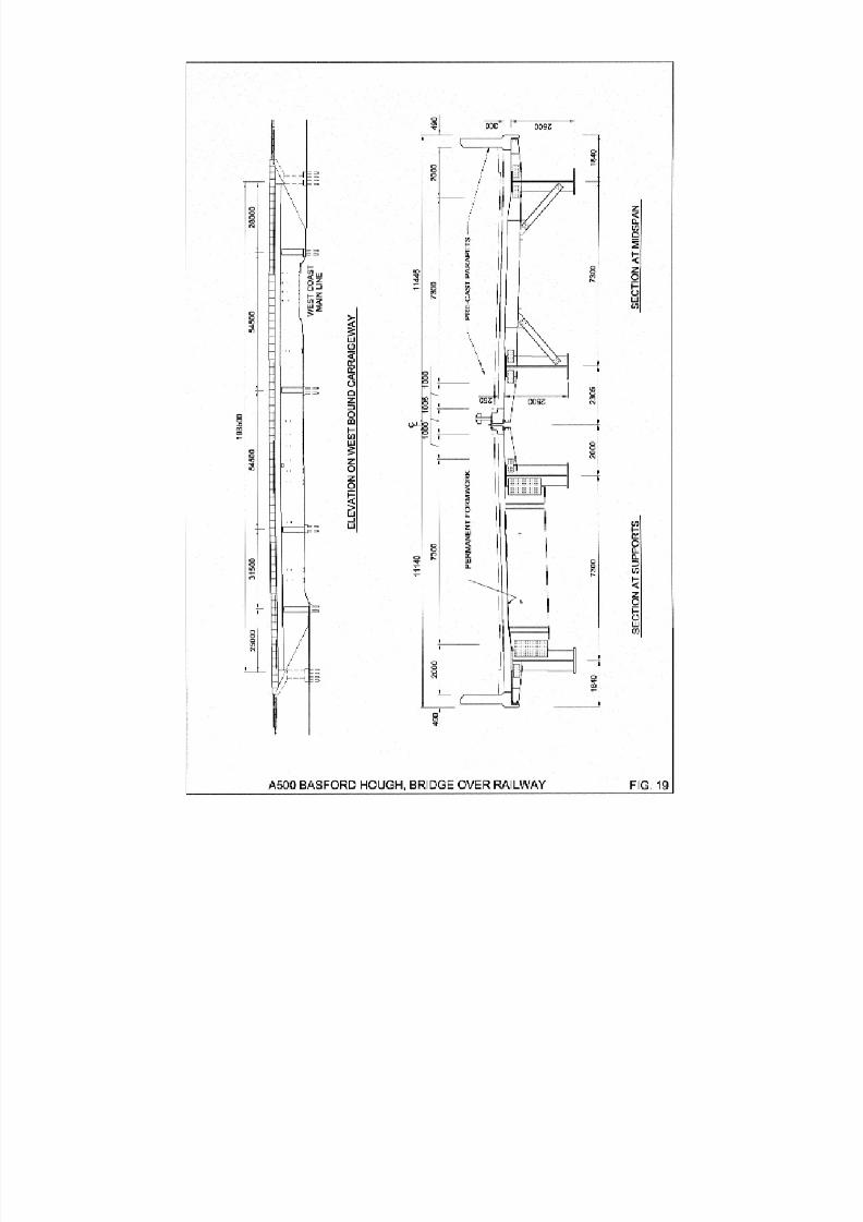
8/7/2019 52512003 Steel Bridges
http://slidepdf.com/reader/full/52512003-steel-bridges 80/96
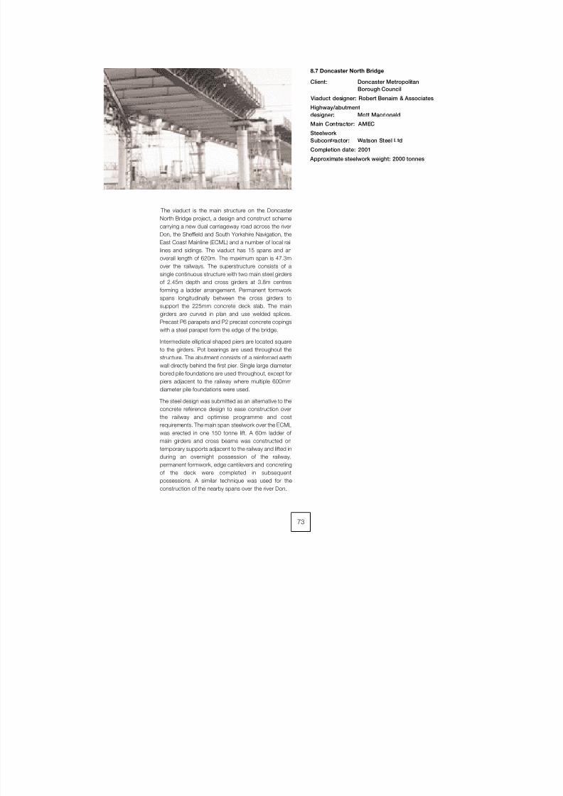
8/7/2019 52512003 Steel Bridges
http://slidepdf.com/reader/full/52512003-steel-bridges 81/96
73
8.7 Doncaster North Bridge
Client: Doncaster Metropolitan
Borough Council
Viaduct designer: Robert Benaim & Associates
Highway/abutment
designer: Mott Macdonald
Main Contractor: AMEC
Steelwork
Subcontractor: Watson Steel Ltd
Completion date: 2001
Approximate steelwork weight: 2000 tonnes
The viaduct is the main structure on the Doncaster
North Bridge project, a design and construct scheme
carrying a new dual carriageway road across the river
Don, the Sheffield and South Yorkshire Navigation, the
East Coast Mainline (ECML) and a number of local rail
lines and sidings. The viaduct has 15 spans and an
overall length of 620m. The maximum span is 47.3m
over the railways. The superstructure consists of a
single continuous structure with two main steel girders
of 2.45m depth and cross girders at 3.8m centres
forming a ladder arrangement. Permanent formwork
spans longitudinally between the cross girders to
support the 225mm concrete deck slab. The main
girders are curved in plan and use welded splices.
Precast P6 parapets and P2 precast concrete copings
with a steel parapet form the edge of the bridge.
Intermediate elliptical shaped piers are located square
to the girders. Pot bearings are used throughout the
structure. The abutment consists of a reinforced earth
wall directly behind the first pier. Single large diameter
bored pile foundations are used throughout, except for
piers adjacent to the railway where multiple 600mm
diameter pile foundations were used.
The steel design was submitted as an alternative to the
concrete reference design to ease construction over
the railway and optimise programme and cost
requirements. The main span steelwork over the ECML
was erected in one 150 tonne lift. A 60m ladder of
main girders and cross beams was constructed on
temporary supports adjacent to the railway and lifted in
during an overnight possession of the railway,
permanent formwork, edge cantilevers and concreting
of the deck were completed in subsequent
possessions. A similar technique was used for the
construction of the nearby spans over the river Don.
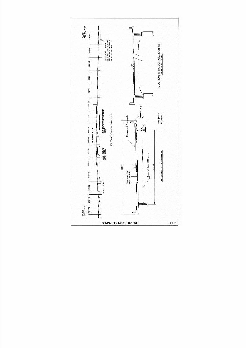
8/7/2019 52512003 Steel Bridges
http://slidepdf.com/reader/full/52512003-steel-bridges 82/96

8/7/2019 52512003 Steel Bridges
http://slidepdf.com/reader/full/52512003-steel-bridges 83/96
75
8.8 A69 Haltwhistle Bypass Railway Viaduct
Client: Road Link (A69) Ltd for
Highways Agency
Design –
Bridge Deck: Cass Hayward & Partners
Design – Substructure: Pell Frischmann
Main Contractor: A69 Haltwhistle Bypass
Joint Venture
Steelwork
Subcontractor: Kvaerner Cleveland Bridge Ltd
Completion date: 1997
Approximate steelwork weight: 770 tonnes
This new viaduct carries the A69 Haltwhistle Bypass
improvement over the Newcastle to Carlisle railway
and Haltwhistle Burn in the north of England. The A69
was the first project under DBFO concession to be
completed in the UK and the railway viaduct was the
most prominent new structure on the route.
The bridge follows a tight 540m radius curve and
supports a single 7.3m wide carriageway with 1m wide
hard strips and a variable width extended verge on the
south side to ensure sight lines are maintained. The
bridge width varies as a consequence andintermediate support locations were constrained by
the skewed alignment of the railway and river below. A
wide "ladder" bridge provided the logical choice to
accommodate these geometrical criteria using a pair of
truly curved steel main plate girders, 3.2m deep, with
cross girders at approximately 3.5m spacing between
them. Concrete deck cantilevers 2.0m long were
maintained throughout the length of the structure for
aesthetic reasons and were designed to
accommodate the loading specification for the P6
parapet required over the railway spans. Three
intermediate piers comprising twin reinforced concrete
columns within the 214m length provided support
under each main girder leading to variable spans
including a maximum span of 68 metres over the
railway. All site joints were made using HSFG bolted
connections and RSA knee braces provide restraint to
bottom flanges in compression at and near to supports
and adjacent to main girder splice positions. The
longer span girders required two site splices within the
length between piers and these were arranged to suit
an erection sequence using cranes progressing from
one abutment and phased installation over the railway
during track possessions.
A special feature of the design was the use of part-
depth precast concrete units for the deck slab
cantilever construction encouraged by the restrictions
of time available for working over the railway. The deck
was cast in three phases, the first phase was for the
complete slab width between the main girders using
Omnia-style permanent formwork spanning between
cross girders. The second phase involved the
installation of precast edge units of two separate forms
– as suited to the P2 and P6 parapet requirements –
and incorporating a temporary over-deck restraint
system which obviated any need to work below top
flange level; separate units provided the wall element
for the P6 parapets. The final phase involved placing
reinforcement and concrete to achieve structural
continuity of the deck and parapet concrete. The
adoption of this method achieved significant
programme benefits and helped to eliminate risks of
delays from winter working in the exposed location.

8/7/2019 52512003 Steel Bridges
http://slidepdf.com/reader/full/52512003-steel-bridges 84/96
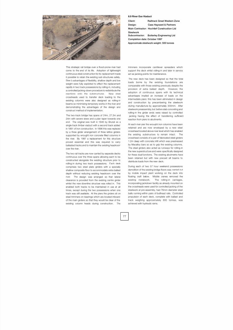
8/7/2019 52512003 Steel Bridges
http://slidepdf.com/reader/full/52512003-steel-bridges 85/96
77
8.9 River Exe Viaduct
Client: Railtrack Great Western Zone
Design: Cass Hayward & Partners
Main Contractor: Hochtief Construction Ltd
Steelwork
Subcontractor: Butterley Engineering Ltd
Completion date: October 1997
Approximate steelwork weight: 500 tonnes
This strategic rail bridge over a flood-prone river had
come to the end of its life. Adoption of lightweight
continuous steel construction for its replacement made
it possible to retain the existing sub-structures safely.
Steel’s advantages of flexibility, shallow depth and lowweight were fully exploited to effect the replacement
rapidly in two track possessions by rolling-in, including
a controlled jacking-down procedure to redistribute the
reactions onto the substructures. New steel
crossheads used to transfer deck loading to the
existing columns were also designed as rolling-in
beams so minimising temporary works in the river and
demonstrating the advantages of the design and
construct method of implementation.
The two-track bridge has spans of 24m, 27.3m and
24m with severe skew and a plan taper towards one
end. The original was built in 1846 by Brunel as asingle track timber viaduct with a second track added
in 1861 of iron construction. In 1896 this was replaced
by a three girder arrangement of three lattice girders
supported by wrought iron concrete filled columns in
the river. By 1997 a replacement for this structure
proved essential and this was required to carry
ballasted tracks and to maintain the existing headroom
over the river.
The two rail tracks are now carried by separate decks
continuous over the three spans allowing each to be
constructed alongside the existing structure prior to
rolling-in during two track possessions. Each deckcomprises two steel plate girders with a specially
shallow composite floor to accommodate extra ballast
depth without reducing existing headroom over the
river. The design was arranged so that lateral
clearance is provided from the existing centre girder
whilst the new downline structure was rolled in. This
enabled both tracks to be maintained in use at all
times, except during the two possessions when one
track was still available. At the piers the girders sit on
steel trimmers on bearings which are located inboard
of the main girders so that they would be clear of the
existing column heads during construction. The
trimmers incorporate cantilever spreaders which
support the deck whilst rolling-in and later in service
act as jacking points for maintenance.
The new deck has been designed so that the total
loads borne by the existing foundations are
comparable with those existing previously despite the
provision of extra ballast depth. However, the
adoption of continuous spans with its technical
advantages implied an increase of loads on the
intermediate piers: this has been eliminated in design
and construction by precambering the steelwork
during manufacture by approximately 300mm. After
steelwork preassembly, but before slab concreting and
rolling-in the girder ends were raised by controlled
jacking having the effect of transferring sufficient
reaction from piers to abutments.
At each river pier the wrought iron columns have been
retained and are now enveloped by a new steel
crosshead located above river level which has enabled
the existing substructure to remain intact. The
crosshead consists of a pair of fabricated steel girders
1.2m deep with concrete infill which was prestressed
by Macalloy bars so as to grip the existing columns.
The steel girders also acted as runways for rolling-in
the new superstructure and were specifically designed
for these dual functions. The existing abutments have
been retained but with new precast sill beams to
distribute loads from the new deck.
During each of two 57 hour weekend possessions
demolition of the existing bridge floors was carried out
by mobile impact plant working on the deck into
floating craft below. Mobile cranes removed the
existing metalwork. The rolling-in carriages,
incorporating jackdown facility as already mounted on
the crossheads were used for controlled jacking of the
steelwork at pre-assembly, had 76mm diameter steel
balls running within pairs of bullhead rails. Controlled
propulsion of each deck, complete with ballast and
track weighing approximately 800 tonnes, was
achieved with hydraulic rams.
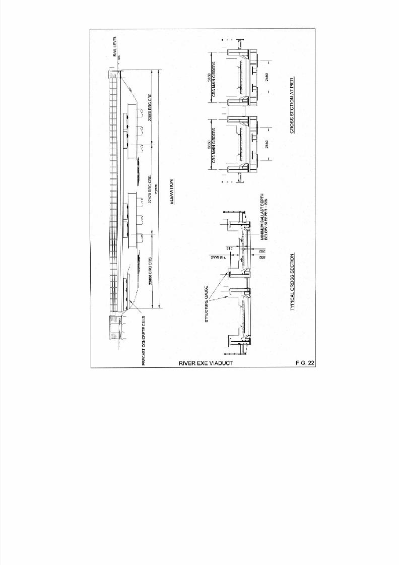
8/7/2019 52512003 Steel Bridges
http://slidepdf.com/reader/full/52512003-steel-bridges 86/96
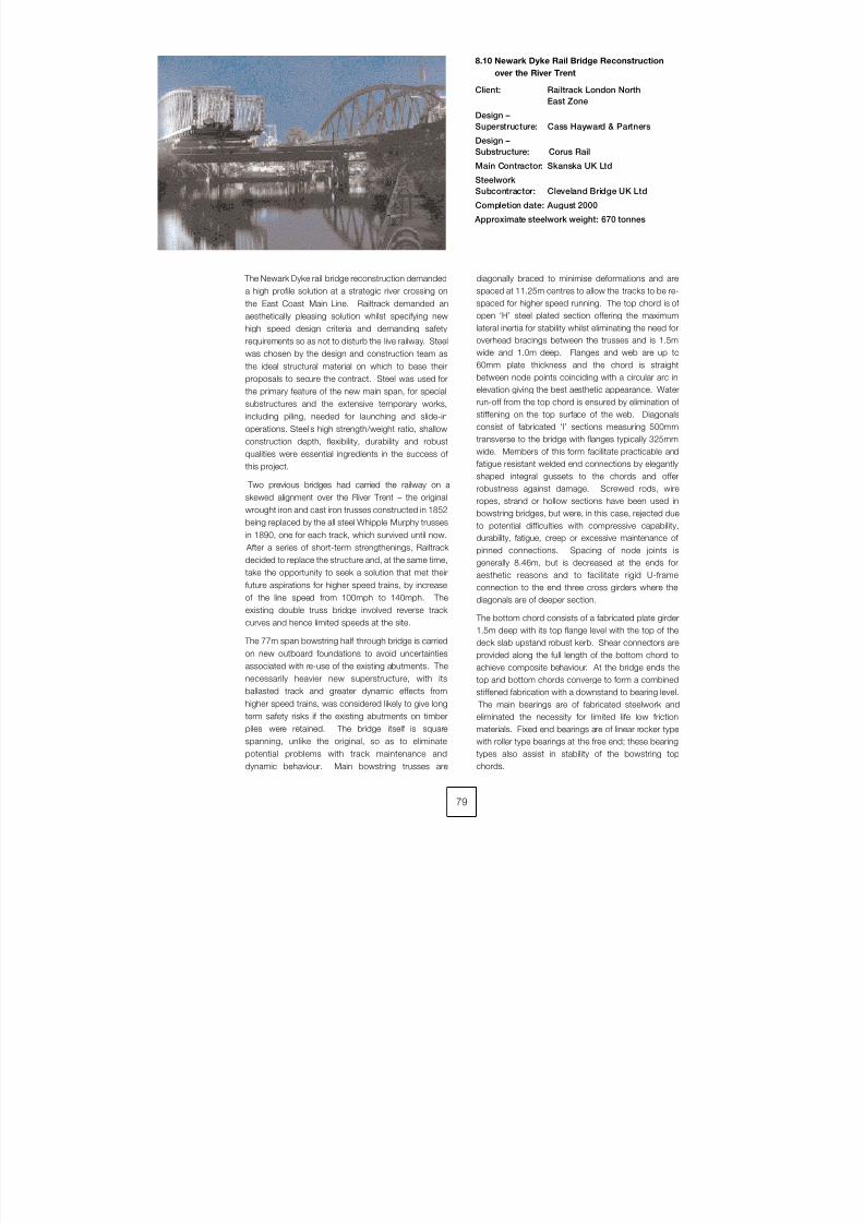
8/7/2019 52512003 Steel Bridges
http://slidepdf.com/reader/full/52512003-steel-bridges 87/96
The Newark Dyke rail bridge reconstruction demanded
a high profile solution at a strategic river crossing on
the East Coast Main Line. Railtrack demanded anaesthetically pleasing solution whilst specifying new
high speed design criteria and demanding safety
requirements so as not to disturb the live railway. Steel
was chosen by the design and construction team as
the ideal structural material on which to base their
proposals to secure the contract. Steel was used for
the primary feature of the new main span, for special
substructures and the extensive temporary works,
including piling, needed for launching and slide-in
operations. Steel’s high strength/weight ratio, shallow
construction depth, flexibility, durability and robust
qualities were essential ingredients in the success of this project.
Two previous bridges had carried the railway on a
skewed alignment over the River Trent – the original
wrought iron and cast iron trusses constructed in 1852
being replaced by the all steel Whipple Murphy trusses
in 1890, one for each track, which survived until now.
After a series of short-term strengthenings, Railtrack
decided to replace the structure and, at the same time,
take the opportunity to seek a solution that met their
future aspirations for higher speed trains, by increase
of the line speed from 100mph to 140mph. The
existing double truss bridge involved reverse track
curves and hence limited speeds at the site.
The 77m span bowstring half through bridge is carried
on new outboard foundations to avoid uncertainties
associated with re-use of the existing abutments. The
necessarily heavier new superstructure, with its
ballasted track and greater dynamic effects from
higher speed trains, was considered likely to give long
term safety risks if the existing abutments on timber
piles were retained. The bridge itself is square
spanning, unlike the original, so as to eliminate
potential problems with track maintenance anddynamic behaviour. Main bowstring trusses are
diagonally braced to minimise deformations and are
spaced at 11.25m centres to allow the tracks to be re-
spaced for higher speed running. The top chord is of open ‘H’ steel plated section offering the maximum
lateral inertia for stability whilst eliminating the need for
overhead bracings between the trusses and is 1.5m
wide and 1.0m deep. Flanges and web are up to
60mm plate thickness and the chord is straight
between node points coinciding with a circular arc in
elevation giving the best aesthetic appearance. Water
run-off from the top chord is ensured by elimination of
stiffening on the top surface of the web. Diagonals
consist of fabricated ‘I’ sections measuring 500mm
transverse to the bridge with flanges typically 325mm
wide. Members of this form facilitate practicable andfatigue resistant welded end connections by elegantly
shaped integral gussets to the chords and offer
robustness against damage. Screwed rods, wire
ropes, strand or hollow sections have been used in
bowstring bridges, but were, in this case, rejected due
to potential difficulties with compressive capability,
durability, fatigue, creep or excessive maintenance of
pinned connections. Spacing of node joints is
generally 8.46m, but is decreased at the ends for
aesthetic reasons and to facilitate rigid U-frame
connection to the end three cross girders where the
diagonals are of deeper section.
The bottom chord consists of a fabricated plate girder
1.5m deep with its top flange level with the top of the
deck slab upstand robust kerb. Shear connectors are
provided along the full length of the bottom chord to
achieve composite behaviour. At the bridge ends the
top and bottom chords converge to form a combined
stiffened fabrication with a downstand to bearing level.
The main bearings are of fabricated steelwork and
eliminated the necessity for limited life low friction
materials. Fixed end bearings are of linear rocker type
with roller type bearings at the free end; these bearing
types also assist in stability of the bowstring topchords.
79
8.10 Newark Dyke Rail Bridge Reconstruction
over the River Trent
Client: Railtrack London North
East Zone
Design –
Superstructure: Cass Hayward & Partners
Design –
Substructure: Corus Rail
Main Contractor: Skanska UK Ltd
Steelwork
Subcontractor: Cleveland Bridge UK Ltd
Completion date: August 2000
Approximate steelwork weight: 670 tonnes
8/7/2019 52512003 Steel Bridges
http://slidepdf.com/reader/full/52512003-steel-bridges 88/96
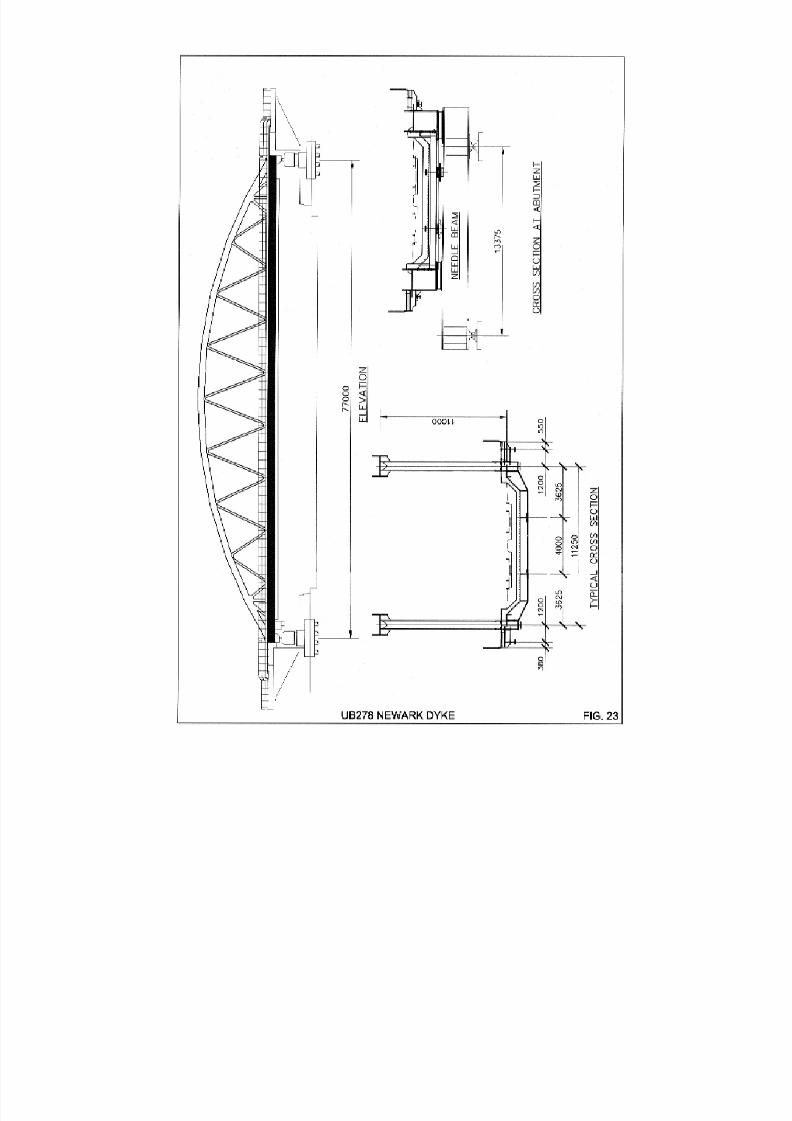
8/7/2019 52512003 Steel Bridges
http://slidepdf.com/reader/full/52512003-steel-bridges 89/96

8/7/2019 52512003 Steel Bridges
http://slidepdf.com/reader/full/52512003-steel-bridges 90/96
82
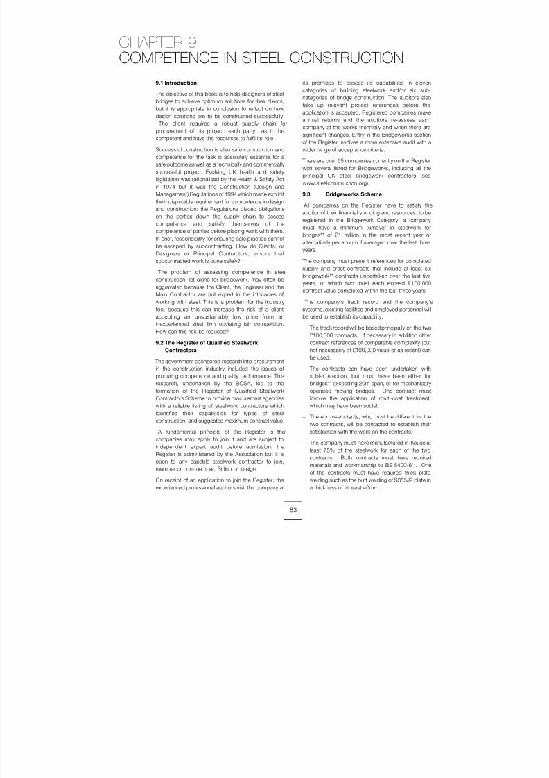
8/7/2019 52512003 Steel Bridges
http://slidepdf.com/reader/full/52512003-steel-bridges 91/96
9.1 Introduction
The objective of this book is to help designers of steelbridges to achieve optimum solutions for their clients,
but it is appropriate in conclusion to reflect on how
design solutions are to be constructed successfully.
The client requires a robust supply chain for
procurement of his project: each party has to be
competent and have the resources to fulfil its role.
Successful construction is also safe construction and
competence for the task is absolutely essential for a
safe outcome as well as a technically and commercially
successful project. Evolving UK health and safety
legislation was rationalised by the Health & Safety Act
in 1974 but it was the Construction (Design and
Management) Regulations of 1994 which made explicit
the indisputable requirement for competence in design
and construction: the Regulations placed obligations
on the parties down the supply chain to assess
competence and satisfy themselves of the
competence of parties before placing work with them.
In brief, responsibility for ensuring safe practice cannot
be escaped by subcontracting. How do Clients, or
Designers or Principal Contractors, ensure that
subcontracted work is done safely?
The problem of assessing competence in steel
construction, let alone for bridgework, may often be
aggravated because the Client, the Engineer and theMain Contractor are not expert in the intricacies of
working with steel. This is a problem for the industry
too, because this can increase the risk of a client
accepting an unsustainably low price from an
inexperienced steel firm obviating fair competition.
How can this risk be reduced?
9.2 The Register of Qualified Steelwork
Contractors
The government sponsored research into procurement
in the construction industry included the issues of
procuring competence and quality performance. This
research, undertaken by the BCSA, led to theformation of the Register of Qualified Steelwork
Contractors Scheme to provide procurement agencies
with a reliable listing of steelwork contractors which
identifies their capabilities for types of steel
construction, and suggested maximum contract value.
A fundamental principle of the Register is that
companies may apply to join it and are subject to
independent expert audit before admission: the
Register is administered by the Association but it is
open to any capable steelwork contractor to join,
member or non-member, British or foreign.
On receipt of an application to join the Register, theexperienced professional auditors visit the company at
its premises to assess its capabilities in eleven
categories of building steelwork and/or six sub-
categories of bridge construction. The auditors also
take up relevant project references before the
application is accepted. Registered companies make
annual returns and the auditors re-assess each
company at the works triennially and when there are
significant changes. Entry in the Bridgeworks section
of the Register involves a more extensive audit with a
wider range of acceptance criteria.
There are over 65 companies currently on the Register
with several listed for Bridgeworks, including all the
principal UK steel bridgework contractors (see
www.steelconstruction.org).
9.3 Bridgeworks Scheme
All companies on the Register have to satisfy the
auditor of their financial standing and resources: to be
registered in the Bridgework Category, a company
must have a minimum turnover in steelwork for
bridges** of £1 million in the most recent year or
alternatively per annum if averaged over the last three
years.
The company must present references for completed
supply and erect contracts that include at least six
bridgework** contracts undertaken over the last five
years, of which two must each exceed £100,000
contract value completed within the last three years.
The company's track record and the company's
systems, existing facilities and employed personnel will
be used to establish its capability.
– The track record will be based principally on the two
£100,000 contracts. If necessary in addition other
contract references of comparable complexity (but
not necessarily of £100,000 value or as recent) can
be used.
– The contracts can have been undertaken with
sublet erection, but must have been either for
bridges** exceeding 20m span, or for mechanicallyoperated moving bridges. One contract must
involve the application of multi-coat treatment,
which may have been sublet.
– The end-user clients, who must be different for the
two contracts, will be contacted to establish their
satisfaction with the work on the contracts.
– The company must have manufactured in-house at
least 75% of the steelwork for each of the two
contracts. Both contracts must have required
materials and workmanship to BS 5400-6**. One
of the contracts must have required thick plate
welding such as the butt welding of S355J2 plate ina thickness of at least 40mm.
83
CHAPTER 9
COMPETENCE IN STEEL CONSTRUCTION
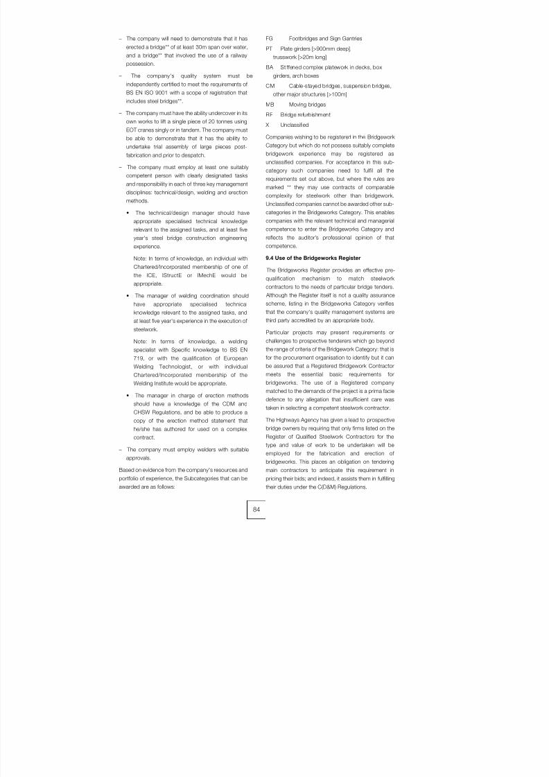
8/7/2019 52512003 Steel Bridges
http://slidepdf.com/reader/full/52512003-steel-bridges 92/96
– The company will need to demonstrate that it has
erected a bridge** of at least 30m span over water,
and a bridge** that involved the use of a railway
possession.
– The company's quality system must be
independently certified to meet the requirements of
BS EN ISO 9001 with a scope of registration that
includes steel bridges**.
– The company must have the ability undercover in its
own works to lift a single piece of 20 tonnes using
EOT cranes singly or in tandem. The company must
be able to demonstrate that it has the ability to
undertake trial assembly of large pieces post-
fabrication and prior to despatch.
– The company must employ at least one suitably
competent person with clearly designated tasks
and responsibility in each of three key management
disciplines: technical/design, welding and erectionmethods.
• The technical/design manager should have
appropriate specialised technical knowledge
relevant to the assigned tasks, and at least five
year's steel bridge construction engineering
experience.
Note: In terms of knowledge, an individual with
Chartered/Incorporated membership of one of
the ICE, IStructE or IMechE would be
appropriate.
• The manager of welding coordination should
have appropriate specialised technical
knowledge relevant to the assigned tasks, and
at least five year's experience in the execution of
steelwork.
Note: In terms of knowledge, a welding
specialist with Specific knowledge to BS EN
719, or with the qualification of European
Welding Technologist, or with individual
Chartered/Incorporated membership of the
Welding Institute would be appropriate.
• The manager in charge of erection methods
should have a knowledge of the CDM and
CHSW Regulations, and be able to produce a
copy of the erection method statement that
he/she has authored for used on a complex
contract.
– The company must employ welders with suitable
approvals.
Based on evidence from the company's resources and
portfolio of experience, the Subcategories that can beawarded are as follows:
FG Footbridges and Sign Gantries
PT Plate girders [>900mm deep],
trusswork [>20m long]
BA Stiffened complex platework in decks, box
girders, arch boxes
CM Cable-stayed bridges, suspension bridges,
other major structures [>100m]MB Moving bridges
RF Bridge refurbishment
X Unclassified
Companies wishing to be registered in the Bridgework
Category but which do not possess suitably complete
bridgework experience may be registered as
unclassified companies. For acceptance in this sub-
category such companies need to fulfil all the
requirements set out above, but where the rules are
marked ** they may use contracts of comparable
complexity for steelwork other than bridgework.
Unclassified companies cannot be awarded other sub-
categories in the Bridgeworks Category. This enables
companies with the relevant technical and managerial
competence to enter the Bridgeworks Category and
reflects the auditor’s professional opinion of that
competence.
9.4 Use of the Bridgeworks Register
The Bridgeworks Register provides an effective pre-
qualification mechanism to match steelwork
contractors to the needs of particular bridge tenders. Although the Register itself is not a quality assurance
scheme, listing in the Bridgeworks Category verifies
that the company's quality management systems are
third party accredited by an appropriate body.
Particular projects may present requirements or
challenges to prospective tenderers which go beyond
the range of criteria of the Bridgework Category: that is
for the procurement organisation to identify but it can
be assured that a Registered Bridgework Contractor
meets the essential basic requirements for
bridgeworks. The use of a Registered companymatched to the demands of the project is a prima facie
defence to any allegation that insufficient care was
taken in selecting a competent steelwork contractor.
The Highways Agency has given a lead to prospective
bridge owners by requiring that only firms listed on the
Register of Qualified Steelwork Contractors for the
type and value of work to be undertaken will be
employed for the fabrication and erection of
bridgeworks. This places an obligation on tendering
main contractors to anticipate this requirement in
pricing their bids; and indeed, it assists them in fulfillingtheir duties under the C(D&M) Regulations.
84

8/7/2019 52512003 Steel Bridges
http://slidepdf.com/reader/full/52512003-steel-bridges 93/96
10.1 Codes and Standards referred to in
this edition
• BS 4-1:1993 Structural steel sections. Specification
for hot-rolled sections
• BS 153: Specification for steel girder bridges.
• BS 153-1 & 2:1972 (withdrawn) Materials and
workmanship. Weighing, shipping and erection
• BS 153-3A:1972 (withdrawn) Loads
• BS 153-3B & 4:1972 (withdrawn) Stresses. Design
and construction
• BS 3692:2001 ISO metric precision hexagon bolts,
screws and nuts. Specification
• BS 4190:2001 ISO metric black hexagon bolts,
screws and nuts. Specification
• BS 4360:1990 (withdrawn) Specification for
weldable structural steels
• BS 4395: Specification for high strength friction grip
bolts and associated nuts and washers for
structural engineering.
BS 4395-1:1969 General grade
BS 4395-2:1969 Higher grade bolts and
nuts and general grade washers
• BS 4570:1985 Specification for fusion welding of
steel castings.
• BS 4604: Specification for the use of high strength
friction grip bolts in structural steelwork.
BS 4604-1:1970 Metric series. General
grade
BS 4604-2:1970 Metric series. Higher
grade (parallel shank)
• BS 4870 (withdrawn): Specification for approval
testing of welding procedures.
BS 4870-1:1981 (withdrawn) Fusion
welding of steel
BS 4870-4:1988 (withdrawn) Specification
for automatic fusion welding of metallic
materials, including welding operator
approval
• BS 5135:1984 (withdrawn) Specification for arc
welding of carbon and carbon manganese steels
• BS 5400: Steel, concrete and composite bridges.
• BS 5400-1:1988 General statement
• BS 5400-2:1978 (partially replaced) Specification
for loads
• BS 5400-3:2000 Code of practice for design of steel bridges
• BS 5400-4:1990 Code of practice for design of
concrete bridges
• BS 5400-5:1979 Code of practice for design of
composite bridges
• BS 5400-6:1999 Specification for materials and
workmanship, steel
• BS 5400-7:1978 Specification for materials and
workmanship, concrete, reinforcement and
prestressing tendons
• BS 5400-8:1978 Recommendations for materials
and workmanship, concrete, reinforcement and
prestressing tendons
• BS 5400-9.1:1983 Bridge bearings. Code of practice for design of bridge bearings
• BS 5400-9.2:1983 Bridge bearings. Specification
for materials, manufacture and installation of bridge
bearings
• BS 5400-10:1980 Code of practice for fatigue
• BS 5400-10C:1999 Charts for classification of
details for fatigue
• BS 5996:1993 (withdrawn) Specification for
acceptance levels for internal imperfections in steel
plate, strip and wide flats, based on ultrasonic
testing
• BS 7644: Direct tension indicators.
BS 7644-1:1993 Specification for
compressible washers
BS 7644-2:1993 Specification for nut face
and bolt face washers
• BS 7668:1994 Specification for weldable structural
steels. Hot finished structural hollow sections in
weather resistant steels
• BS EN 287: Approval testing of welders for fusion
welding.
BS EN 287-1:1992 Steels• BS EN 288: Specification and approval of welding
procedures for metallic materials.
BS EN 288-1:1992 General rules for fusion
welding
BS EN 288-2:1992 Welding procedures
specification for arc welding
BS EN 288-3:1992 Welding procedure
tests for the arc welding of steels
• BS EN 1011: Welding. Recommendations for
welding of metallic materials.
BS EN 1011-1:1998 General guidance forarc welding
85
CHAPTER 10
REFERENCES
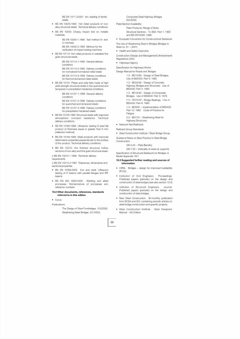
8/7/2019 52512003 Steel Bridges
http://slidepdf.com/reader/full/52512003-steel-bridges 94/96
BS EN 1011-2:2001 Arc welding of ferritic
steels
• BS EN 10025:1993 Hot rolled products of non-
alloy structural steels. Technical delivery conditions
• BS EN 10045: Charpy impact test on metallic
materials.
BS EN 10045-1:1990 Test method (V- and
U-notches)
BS EN 10045-2:1993 Method for the
verification of impact testing machines
• BS EN 10113: Hot-rolled products in weldable fine
grain structural steels.
BS EN 10113-1:1993 General delivery
conditions
BS EN 10113-2:1993 Delivery conditions
for normalized/normalized rolled steels
BS EN 10113-3:1993 Delivery conditions
for thermomechanical rolled steels
• BS EN 10137: Plates and wide flats made of highyield strength structural steels in the quenched and
tempered or precipitation hardened conditions.
BS EN 10137-1:1996 General delivery
conditions
BS EN 10137-2:1996 Delivery conditions
for quenched and tempered steels
BS EN 10137-3:1996 Delivery conditions
for precipitation hardened steels
• BS EN 10155:1993 Structural steels with improved
atmospheric corrosion resistance. Technical
delivery conditions
• BS EN 10160:1999 Ultrasonic testing of steel flatproduct of thickness equal or greater than 6 mm
(reflection method)
• BS EN 10164:1993 Steel products with improved
deformation properties perpendicular to the surface
of the product. Technical delivery conditions
• BS EN 10210: Hot finished structural hollow
sections of non-alloy and fine grain structural steels.
o BS EN 10210-1:1994 Technical delivery
requirements
o BS EN 10210-2:1997 Tolerances, dimensions and
sectional properties
• BS EN 10306:2002 Iron and steel. Ultrasonic
testing of H beams with parallel flanges and IPE
beams
• BS EN ISO 4063:2000 Welding and allied
processes. Nomenclature of processes and
reference numbers
10.2 Other documents, references, standards
referred to in this edition
• Corus
Publications:
The Design of Steel Footbridges (10/2000)Weathering Steel Bridges (01/2002)
Composite Steel Highway Bridges
(02/2002)
Plate/Section Availability:
Plate Products: Range of Sizes
Structural Sections - To BS4: Part 1: 1993
and BS EN10056: 1999
• European Convention for Constructional Steelwork
The Use of Weathering Steel in Bridges (Bridges in
Steel no. 81 – 2001)
• Health and Safety Executive
Construction (Design and Management) (Amendment)
Regulations 2000
• Highways Agency
Specification for Highways Works
Design Manual for Roads and Bridges
1.3 - BD13/90 - Design of Steel Bridges.
Use of BS5400: Part 3: 1982
1.3 - BD24/92 - Design of ConcreteHighway Bridges and Structures. Use of
BS5400: Part 4: 1990
1.3 - BD16/82 - Design of Composite
Bridges. Use of BS5400: Part 5: 1979
2.3 - BD20/92 - Bridge Bearings. Use of
BS5400: Part 9: 1983
1.3 - BD9/81 – Implementation of BS5400:
Part 10: 1980 – Code of Practice for
Fatigue
2.3 - BD7/01 - Weathering Steel for
Highway Structures
• Network Rail (Railtrack)Railtrack Group Standards
• Steel Construction Institute / Steel Bridge Group.
Guidance Notes on Best Practice in Steel Bridge
Construction:
GN 5.04 – Plate Bending
GN 7.03 – Verticality of webs at supports
Specification of Structural Steelwork for Bridges: A
Model Appendix 18/1
10.3 Suggested further reading and sources of
information
• CIRIA. Bridges – design for improved buildability(R155).
• Institution of Civil Engineers. Proceedings.
Published papers (periodic) on the design and
construction of steel bridges (see also section 10.X)
• nstitution of Structural Engineers. Journal.
Published papers (periodic) on the design and
construction of steel bridges.
• New Steel Construction. Bi-monthly publication
from BCSA and SCI, containing periodic articles on
steel bridge construction and specific projects.
• Steel Construction Institute. Steel Designers’Manual – 5th Edition
86
8/7/2019 52512003 Steel Bridges
http://slidepdf.com/reader/full/52512003-steel-bridges 95/96
• Steel Construction Institute / Steel Bridge Group.
Guidance Notes on Best Practice in Steel Bridge
Construction – 3rd issue. 2002.
The Steel Bridge group is a technical forum
established to consider matters of high priority and
interest to the steel bridge construction industry and
to suggest strategies for improving the use of steel in
bridgework. This publication presents a collection of
separate Guidance Notes on a wide range of topics
concerning the design and construction of steel
bridges: it covers design, materials, contract
documentation, fabrication, inspection and testing,
erection and protective treatment. The representation
of diverse interests in the Group means that the
Guidance Notes can be considered to be guides to
good, accepted practice.
• Steel Construction Institute. Series of publication
relating to bridge design, including design guides
and worked examples, commentaries on relevant
Standards and Specification guidance.
• The Welding Institute. Published papers on weldingaspects of the fabrication of steel bridges.
10.4 References used within the text of the
first edition
• BS4: Part 1: 1980. Specification for hot rolled
sections.
• BS153: Parts 3B and 4: 1972. Steel Girder
Bridges.
Part 3B: Stresses Part 4: Design and construction.
• BS4360: 1979. Specification for weldable
structural steels.
• BS5135: 1984. Process of arc welding of carbonand carbon manganese steels
• DD21: 1972. Quality grading of steel plate from
12mm to 150mm thick by means of ultrasonic
testing.
• PD6493: 1980. Guidance on some methods for
the derivation of acceptance levels for defects in
fusion welded joints.
• American Iron and Steel Institute - Task group on
weathering steel bridges. 1982.
Performances of weathering steel in highway bridges
- A first phase report.• BCSA. New developments in steel construction
part 11 – bridges.
• BCSA. Structural steelwork – fabrication.
• Branco, FA and Green R. 1982. Construction
bracing for composite box girder bridges.
International conference on short and medium span
bridges, Toronto.
• British Bridge Builders. 1981. Bridging the
Humber. Compiled by G Wilkinson.
• Constrado. 1983. Weather resistant steel for
bridgework.
• Constrado. 1984. Steel bridge design guide –
composite UB simply supported span (by GFJ
Nash).
• Blodgett OW. 1972. "Distortion …. How Metal
Properties Affect It". Welding Engineer, February.
• Burdekin, Prof. FM. 1981. "To control distortion,
keep it flat, keep it straight". Metal Construction,
October.
• Freeman RA. 1977. Erection of Avonmouth
Bridge. Acier: Stahl: Steel 5. 1977.
• Hansen, B. 1973. "Formulas for residual welding
stresses and distortions". The Danish Welding
Institute. Publication P73044.
• Hayward ACGH. 1984. Alternative designs of
shorter span bridges. National Structural Steel
Conference. New developments in steel
construction. London.
• HMSO. 1973. Inquiry into the basis of design and
method of erection of steel box girder bridges.
Report of the Committee – Appendix 1 Interim
design and workmanship rules (known as Merrison
Rules or IDWR)
• Hunter IE & McKeown ME, 1984 "Foyle Bridge:
Fabrication and Construction of the Main Spans".
Proceedings ICE, vol 76, May.
• Hyatt KE. 1968 "Severn Bridge: Fabrication &
Erection". Proceedings ICE vol 41, September.
• Kerensky OA and Dallard NJ. 1968. The four level
interchange between M4 and M5 motorways at
Almondsbury. Proceedings ICE vol 40 July. p295-
321.
• Leggatt RH & White JD. "Predicted shrinkage &
distortion in a welded plate". Proceedings of 1977
Conference on Residual Stresses in Welded
Construction and Their Effects. TWI.
• Paton J, Fraser DD, Davidson JB. 1968. Special
features of Hamilton bypass motorway (M74).
Proceedings, ICE vol 41, October.
• Roberts Sir Gilbert, 1968 "Severn Bridge: Design
and Construct Arrangements". Proceedings, ICE
vol 41, September.
• Wex BP, Gillespie NM and Kinsella J, 1984 "Foyle
Bridge: Design & Tender in a Design & BuildingCompetition". Proceedings, ICE vol 76, May.
• White JD, Leggatt RH and Dwight JB. 1979.
"Weld shrinkage prediction". Second International
Conference on Offshore Structures. Paper 19,
Imperial College, London.
10.5 Articles about early steel bridges
This list was provided by the Library of the Institution
of Civil Engineers to whom reference can be made to
examine or obtain copies of the articles given below:
• Baker, Sir B. Steel in railway structures. ICE Min
Procs vol 85, 1886. pp140.
87
8/7/2019 52512003 Steel Bridges
http://slidepdf.com/reader/full/52512003-steel-bridges 96/96
• Bernhard, C. Steel arched road bridge over the
Neckar at Mannheim. ICE Min Procs vol 147, 1902.
pp445-6; vol 150, 1902. p478.
• Bhvr, WH. The Ohio bridge of the Cincinnatti and
Conington Elevated Railway. ICE Min Procs vol 103,
1890. pp411-415.
• Bischoff, F. On the use of steel in bridge
construction. ICE Min Procs vol 107, 1891.pp452-455.
• Brady, AB. Herbert River bridge, Gairloch,
Queensland. ICE Min Procs vol 124, 1896. pp324-
334.
• Bridge over the Mississippi at Memphis. ICE Min
Procs vol 109, 1892. pp445-446.
• Burge, CO. The Hawkesbury bridge, New South
Wales. ICE Min Procs vol 101, 1890. pp2-12.
• Clarke, TC. The design of iron bridges of very large
span for railway traffic. ICE Min Procs vol 84, 1886.
pp179-250, esp p192.
• Cooper, T. The use of steel for bridges. ASCE
Transactions, vol 8. pp283-.
• Crofts, HA. New bridge, Portland, USA. ICE Min
Procs vol 165, 1906. pp392.
• Crultwell, GEW and Hornfray, SG. Tower Bridge.
ICE Min Procs vol 127, 1897. pp35-82.
• Dumas, A. Alexander III bridge over the Seine. ICE
Min Procs vol 130, 1897. pp335-6.
• Frere, FH. Reconstruction of Midland Railway
Bridge across the River Trent. ICE Min Procs vol
154, 1903. pp267-276.• Goldsmith, AJ. Burnett and Kennedy Bridges,
Bundaberg, Queensland. ICE Min Procs vol 153,
1903. pp267-279.
• Guadard, J. Correspondence on the erection of
iron bridges. ICE Min Procs vol 157, 1904. pp248-
253.
• Hackney, W. The manufacture of steel. ICE Min
Procs vol 42, 1875 pp2-68
• Hallopeau, PFA. Employment of mild steel in
railway bridges. ICE Min Procs vol 96, 1889.
pp371-372.
• Jackson, CFV. Design and construction of steel
bridge work with particulars of a recent example in
Queensland. ICE Min Procs vol 142, 1900. pp253-
271.
• Klette, H. Queen Carola Bridge, Dresden. ICE Min
Procs vol 130, 1987. pp336-7.
• Krolm, R. Use of steel in bridge construction. ICE
Min Procs vol 107, 1891. pp450-452.
• Krossen road bridge over the Oder. ICE Min Procs
vol 170, 1907. pp409.
• Laurie, KA. Jubilee bridge over the River Hooghly.
ICE Min Procs vol 158, 1904. pp374-379.
• Matheson, E. Steel for Structures. ICE Min Procs
vol 69, 1882. pp1-78, esp pp63-64.
• Nansouty, M de. Road bridge over the Rhone at
Lyons. ICE Min Procs vol 108, 1892. pp430-432.
• Nansouty, M de. The new bridge over the Rhone at
Lyons. ICE Min Procs vol 106, 1891. pp360-2.
• New Westminster Bridge over the Fraser River,
British Colombia. ICE Min Procs vol 164, 1906.
pp447-448.
• Ridder, FW and Fox, FD. Great Central railway
extension. ICE Min Procs vol 142, 1900. pp5-75.
• Roberts-Austen, Sir W. Use of cast steel in the
Alexander III bridge. ICE Min Procs vol 150, 1902.
pp164-66.
• Sharpe, W. On some methods of steel bridge
erection. ICE Min Procs vol 150, 1902. pp352-360.
• Shaw, WR. Teesta bridge. ICE Min Procs vol 150,
1902. pp361-375.
• Smith, JT. On Bessemer steel rails. ICE Min Procs
vol 42, 1875. pp69-75. Discussion esp pp95-97.
• Smith, M. Steel and iron railway bridges in Canada.
ICE Min Procs vol 117, 1893.
pp315-318.
• Taylor, WO., Damodar Coal Line Bridge. ICE Min
Procs vol 160, 1904. pp315-325.
• Walton, FTG. Construction of the Dufferin Bridge
over the Granges at Benares. ICE Min Procs vol
101, 1890. pp13-24 and discussion pp38-72.