517657 Diagnostics RF610 RF540 RF201 I&W · 517657 4 Diagnostics A spanner symbol and LCD fault...
17
517657 Fisher & Paykel Appliances © 2007 Sep 2011 Diagnostic Manual Models: RF610A, RF540A, RF201A
Transcript of 517657 Diagnostics RF610 RF540 RF201 I&W · 517657 4 Diagnostics A spanner symbol and LCD fault...

517657
Fisher & Paykel Appliances © 2007 Sep 2011
Diagnostic Manual
Models: RF610A, RF540A, RF201A
517657
2
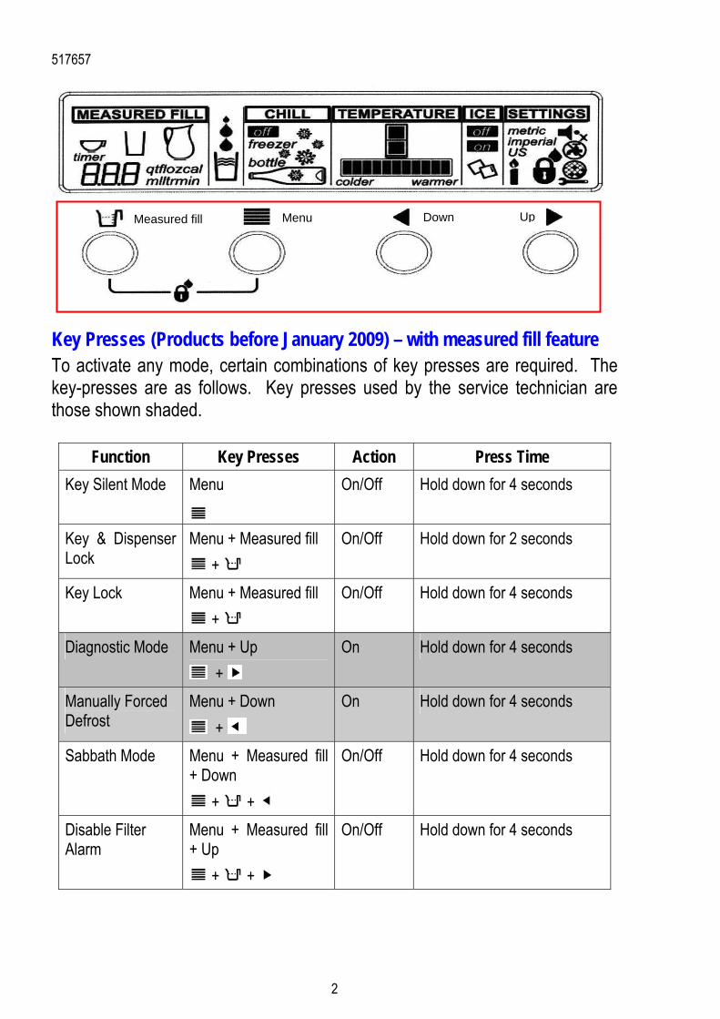
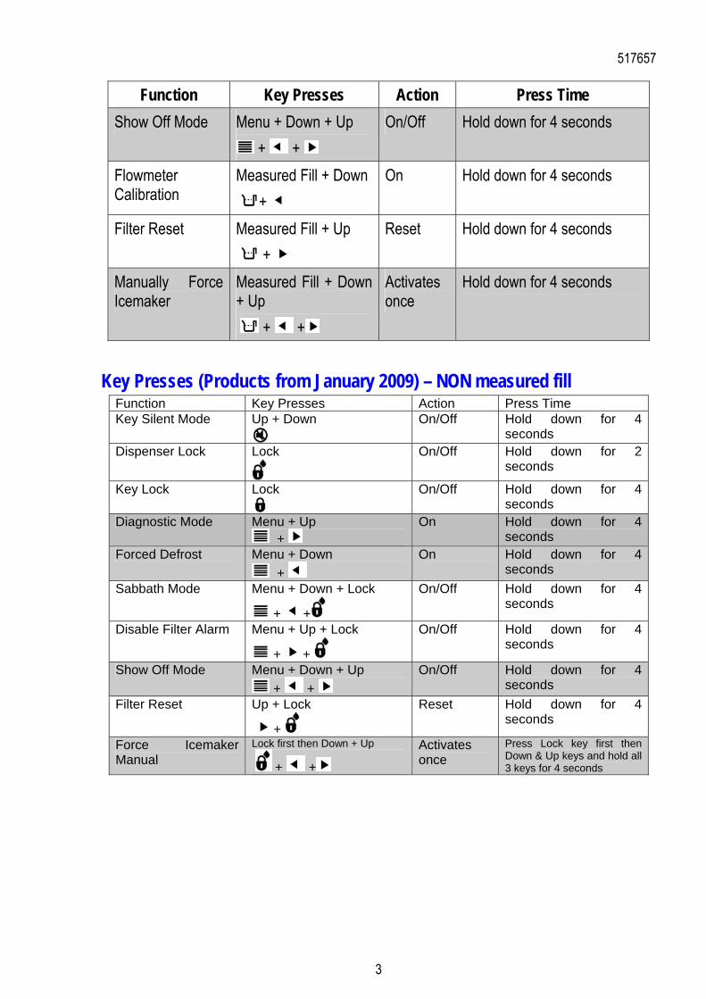
Key Presses (Products before January 2009) – with measured fill feature To activate any mode, certain combinations of key presses are required. The key-presses are as follows. Key presses used by the service technician are those shown shaded.
Function Key Presses Action Press Time
Key Silent Mode Menu
On/Off Hold down for 4 seconds
Key & Dispenser Lock
Menu + Measured fill
+
On/Off Hold down for 2 seconds
Key Lock Menu + Measured fill
+
On/Off Hold down for 4 seconds
Diagnostic Mode Menu + Up
+
On Hold down for 4 seconds
Manually Forced Defrost
Menu + Down
+
On Hold down for 4 seconds
Sabbath Mode Menu + Measured fill + Down
+ +
On/Off Hold down for 4 seconds
Disable Filter Alarm
Menu + Measured fill + Up
+ +
On/Off Hold down for 4 seconds
Down Up MenuMeasured fill
517657
3
Function Key Presses Action Press Time
Show Off Mode Menu + Down + Up
+ +
On/Off Hold down for 4 seconds
Flowmeter Calibration
Measured Fill + Down
+
On Hold down for 4 seconds
Filter Reset Measured Fill + Up
+
Reset Hold down for 4 seconds
Manually Force Icemaker
Measured Fill + Down + Up
+ +
Activates once
Hold down for 4 seconds
Key Presses (Products from January 2009) – NON measured fill Function Key Presses Action Press Time Key Silent Mode Up + Down
On/Off Hold down for 4 seconds
Dispenser Lock Lock
On/Off Hold down for 2 seconds
Key Lock Lock
On/Off Hold down for 4 seconds
Diagnostic Mode Menu + Up +
On Hold down for 4 seconds
Forced Defrost Menu + Down
+
On Hold down for 4 seconds
Sabbath Mode Menu + Down + Lock
+ +
On/Off Hold down for 4 seconds
Disable Filter Alarm Menu + Up + Lock
+ +
On/Off Hold down for 4 seconds
Show Off Mode Menu + Down + Up
+ +
On/Off Hold down for 4 seconds
Filter Reset Up + Lock
+
Reset Hold down for 4 seconds
Force Icemaker Manual
Lock first then Down + Up
+ +
Activates once
Press Lock key first then Down & Up keys and hold all 3 keys for 4 seconds
517657
4
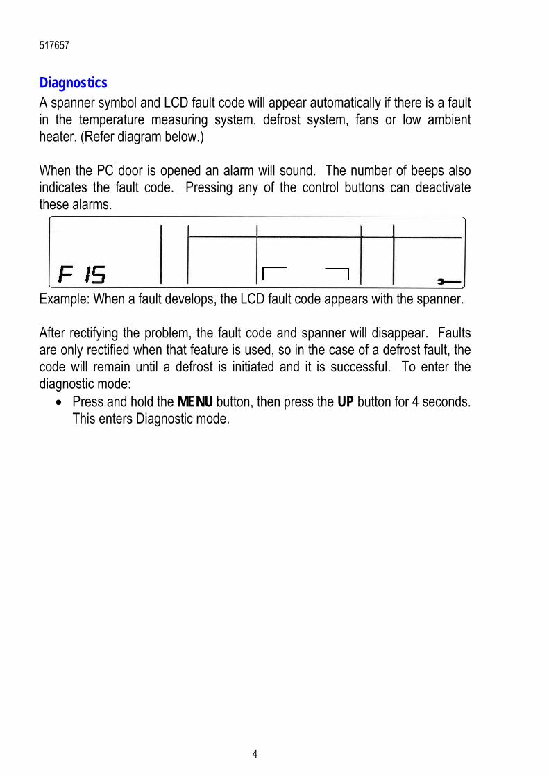
Diagnostics A spanner symbol and LCD fault code will appear automatically if there is a fault in the temperature measuring system, defrost system, fans or low ambient heater. (Refer diagram below.) When the PC door is opened an alarm will sound. The number of beeps also indicates the fault code. Pressing any of the control buttons can deactivate these alarms.
Example: When a fault develops, the LCD fault code appears with the spanner. After rectifying the problem, the fault code and spanner will disappear. Faults are only rectified when that feature is used, so in the case of a defrost fault, the code will remain until a defrost is initiated and it is successful. To enter the diagnostic mode:
Press and hold the MENU button, then press the UP button for 4 seconds. This enters Diagnostic mode.
517657
5
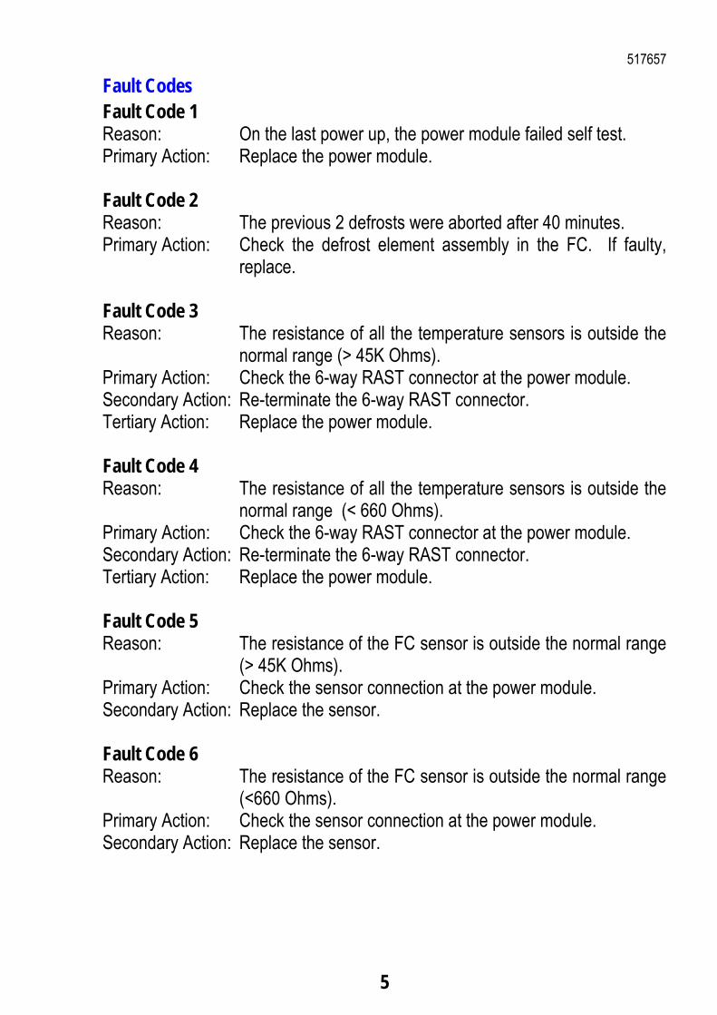
Fault Codes Fault Code 1 Reason: On the last power up, the power module failed self test. Primary Action: Replace the power module. Fault Code 2 Reason: The previous 2 defrosts were aborted after 40 minutes. Primary Action: Check the defrost element assembly in the FC. If faulty,
replace. Fault Code 3 Reason: The resistance of all the temperature sensors is outside the
normal range (> 45K Ohms). Primary Action: Check the 6-way RAST connector at the power module. Secondary Action: Re-terminate the 6-way RAST connector. Tertiary Action: Replace the power module. Fault Code 4 Reason: The resistance of all the temperature sensors is outside the
normal range (< 660 Ohms). Primary Action: Check the 6-way RAST connector at the power module. Secondary Action: Re-terminate the 6-way RAST connector. Tertiary Action: Replace the power module. Fault Code 5 Reason: The resistance of the FC sensor is outside the normal range
(> 45K Ohms). Primary Action: Check the sensor connection at the power module. Secondary Action: Replace the sensor. Fault Code 6 Reason: The resistance of the FC sensor is outside the normal range
(<660 Ohms). Primary Action: Check the sensor connection at the power module. Secondary Action: Replace the sensor.
517657
6
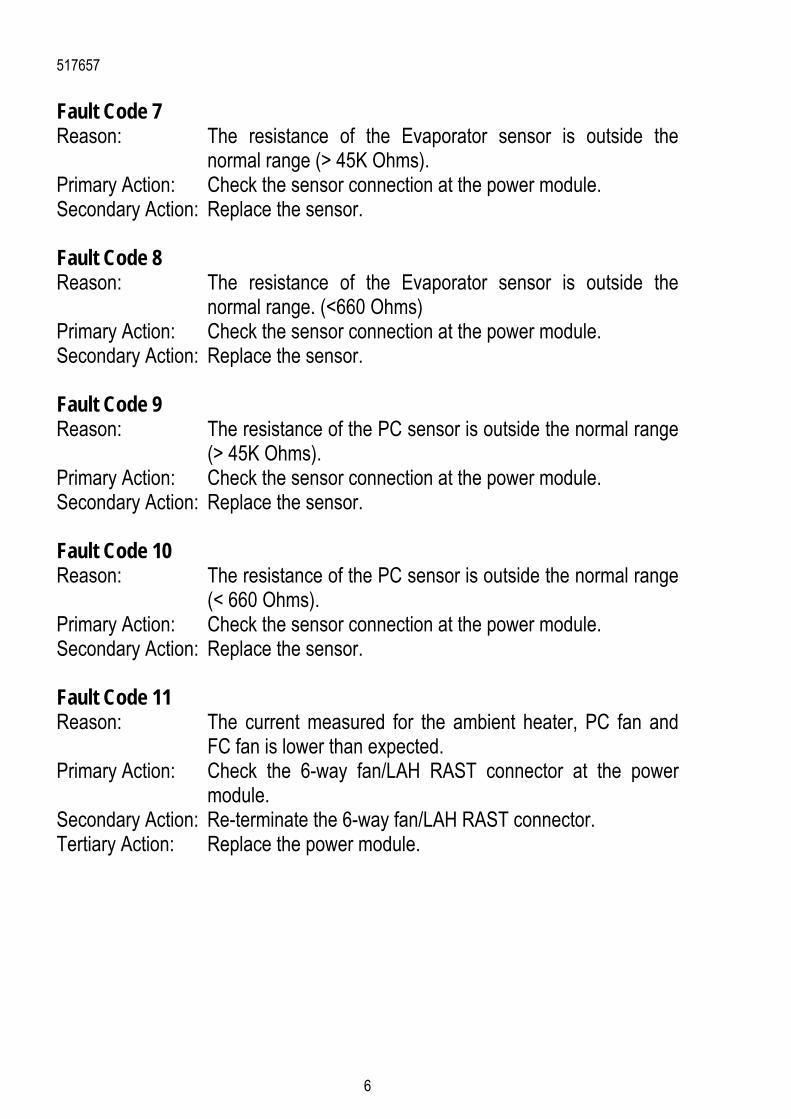
Fault Code 7 Reason: The resistance of the Evaporator sensor is outside the
normal range (> 45K Ohms). Primary Action: Check the sensor connection at the power module. Secondary Action: Replace the sensor. Fault Code 8 Reason: The resistance of the Evaporator sensor is outside the
normal range. (<660 Ohms) Primary Action: Check the sensor connection at the power module. Secondary Action: Replace the sensor. Fault Code 9 Reason: The resistance of the PC sensor is outside the normal range
(> 45K Ohms). Primary Action: Check the sensor connection at the power module. Secondary Action: Replace the sensor. Fault Code 10 Reason: The resistance of the PC sensor is outside the normal range
(< 660 Ohms). Primary Action: Check the sensor connection at the power module. Secondary Action: Replace the sensor. Fault Code 11 Reason: The current measured for the ambient heater, PC fan and
FC fan is lower than expected. Primary Action: Check the 6-way fan/LAH RAST connector at the power
module. Secondary Action: Re-terminate the 6-way fan/LAH RAST connector. Tertiary Action: Replace the power module.
517657
7
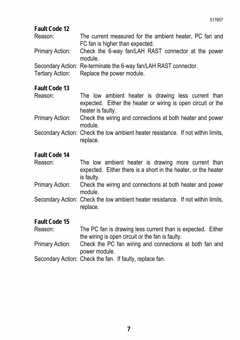
Fault Code 12 Reason: The current measured for the ambient heater, PC fan and
FC fan is higher than expected. Primary Action: Check the 6-way fan/LAH RAST connector at the power
module. Secondary Action: Re-terminate the 6-way fan/LAH RAST connector. Tertiary Action: Replace the power module. Fault Code 13 Reason: The low ambient heater is drawing less current than
expected. Either the heater or wiring is open circuit or the heater is faulty.
Primary Action: Check the wiring and connections at both heater and power module.
Secondary Action: Check the low ambient heater resistance. If not within limits, replace.
Fault Code 14 Reason: The low ambient heater is drawing more current than
expected. Either there is a short in the heater, or the heater is faulty.
Primary Action: Check the wiring and connections at both heater and power module.
Secondary Action: Check the low ambient heater resistance. If not within limits, replace.
Fault Code 15 Reason: The PC fan is drawing less current than is expected. Either
the wiring is open circuit or the fan is faulty. Primary Action: Check the PC fan wiring and connections at both fan and
power module. Secondary Action: Check the fan. If faulty, replace fan.
517657
8
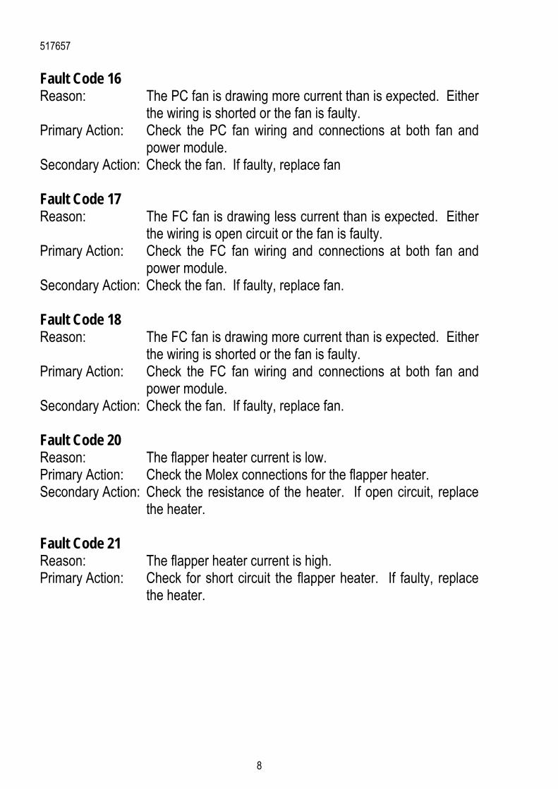
Fault Code 16 Reason: The PC fan is drawing more current than is expected. Either
the wiring is shorted or the fan is faulty. Primary Action: Check the PC fan wiring and connections at both fan and
power module. Secondary Action: Check the fan. If faulty, replace fan Fault Code 17 Reason: The FC fan is drawing less current than is expected. Either
the wiring is open circuit or the fan is faulty. Primary Action: Check the FC fan wiring and connections at both fan and
power module. Secondary Action: Check the fan. If faulty, replace fan. Fault Code 18 Reason: The FC fan is drawing more current than is expected. Either
the wiring is shorted or the fan is faulty. Primary Action: Check the FC fan wiring and connections at both fan and
power module. Secondary Action: Check the fan. If faulty, replace fan. Fault Code 20 Reason: The flapper heater current is low. Primary Action: Check the Molex connections for the flapper heater. Secondary Action: Check the resistance of the heater. If open circuit, replace
the heater. Fault Code 21 Reason: The flapper heater current is high. Primary Action: Check for short circuit the flapper heater. If faulty, replace
the heater.
517657
9
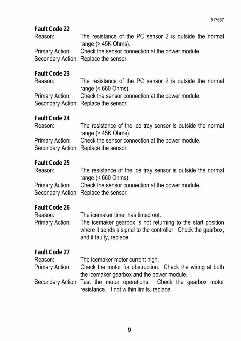
Fault Code 22 Reason: The resistance of the PC sensor 2 is outside the normal
range (> 45K Ohms). Primary Action: Check the sensor connection at the power module. Secondary Action: Replace the sensor. Fault Code 23 Reason: The resistance of the PC sensor 2 is outside the normal
range (< 660 Ohms). Primary Action: Check the sensor connection at the power module. Secondary Action: Replace the sensor. Fault Code 24 Reason: The resistance of the ice tray sensor is outside the normal
range (> 45K Ohms). Primary Action: Check the sensor connection at the power module. Secondary Action: Replace the sensor. Fault Code 25 Reason: The resistance of the ice tray sensor is outside the normal
range (< 660 Ohms). Primary Action: Check the sensor connection at the power module. Secondary Action: Replace the sensor. Fault Code 26 Reason: The icemaker timer has timed out. Primary Action: The icemaker gearbox is not returning to the start position
where it sends a signal to the controller. Check the gearbox, and if faulty, replace.
Fault Code 27 Reason: The icemaker motor current high. Primary Action: Check the motor for obstruction. Check the wiring at both
the icemaker gearbox and the power module. Secondary Action: Test the motor operations. Check the gearbox motor
resistance. If not within limits, replace.
517657
10
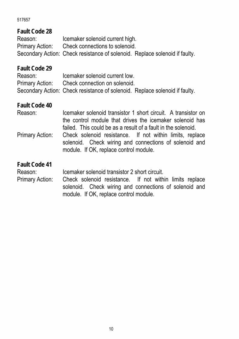
Fault Code 28 Reason: Icemaker solenoid current high. Primary Action: Check connections to solenoid. Secondary Action: Check resistance of solenoid. Replace solenoid if faulty. Fault Code 29 Reason: Icemaker solenoid current low. Primary Action: Check connection on solenoid. Secondary Action: Check resistance of solenoid. Replace solenoid if faulty. Fault Code 40 Reason: Icemaker solenoid transistor 1 short circuit. A transistor on
the control module that drives the icemaker solenoid has failed. This could be as a result of a fault in the solenoid.
Primary Action: Check solenoid resistance. If not within limits, replace solenoid. Check wiring and connections of solenoid and module. If OK, replace control module.
Fault Code 41 Reason: Icemaker solenoid transistor 2 short circuit. Primary Action: Check solenoid resistance. If not within limits replace
solenoid. Check wiring and connections of solenoid and module. If OK, replace control module.
517657
11
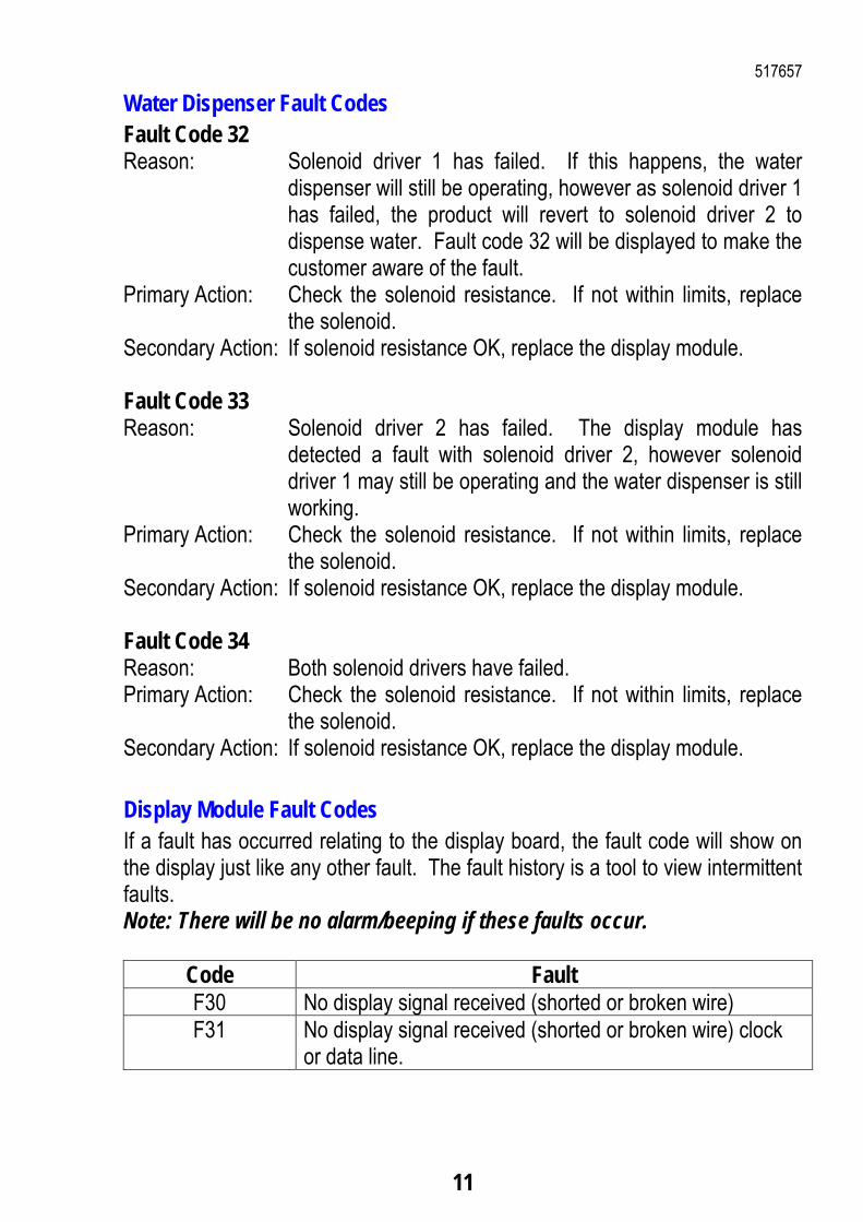
Water Dispenser Fault Codes Fault Code 32 Reason: Solenoid driver 1 has failed. If this happens, the water
dispenser will still be operating, however as solenoid driver 1 has failed, the product will revert to solenoid driver 2 to dispense water. Fault code 32 will be displayed to make the customer aware of the fault.
Primary Action: Check the solenoid resistance. If not within limits, replace the solenoid.
Secondary Action: If solenoid resistance OK, replace the display module. Fault Code 33 Reason: Solenoid driver 2 has failed. The display module has
detected a fault with solenoid driver 2, however solenoid driver 1 may still be operating and the water dispenser is still working.
Primary Action: Check the solenoid resistance. If not within limits, replace the solenoid.
Secondary Action: If solenoid resistance OK, replace the display module. Fault Code 34 Reason: Both solenoid drivers have failed. Primary Action: Check the solenoid resistance. If not within limits, replace
the solenoid. Secondary Action: If solenoid resistance OK, replace the display module.
Display Module Fault Codes If a fault has occurred relating to the display board, the fault code will show on the display just like any other fault. The fault history is a tool to view intermittent faults. Note: There will be no alarm/beeping if these faults occur.
Code Fault F30 No display signal received (shorted or broken wire) F31 No display signal received (shorted or broken wire) clock
or data line.
517657
12
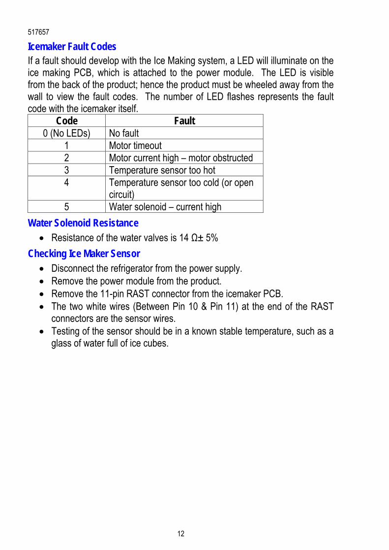
Icemaker Fault Codes If a fault should develop with the Ice Making system, a LED will illuminate on the ice making PCB, which is attached to the power module. The LED is visible from the back of the product; hence the product must be wheeled away from the wall to view the fault codes. The number of LED flashes represents the fault code with the icemaker itself.
Code Fault 0 (No LEDs) No fault
1 Motor timeout 2 Motor current high – motor obstructed 3 Temperature sensor too hot 4 Temperature sensor too cold (or open
circuit) 5 Water solenoid – current high
Water Solenoid Resistance Resistance of the water valves is 14 Ω± 5%
Checking Ice Maker Sensor Disconnect the refrigerator from the power supply. Remove the power module from the product. Remove the 11-pin RAST connector from the icemaker PCB. The two white wires (Between Pin 10 & Pin 11) at the end of the RAST
connectors are the sensor wires. Testing of the sensor should be in a known stable temperature, such as a
glass of water full of ice cubes.

517657
13
Icemaker Sensor Resistance Table Temperature
(ºC) Resistance (K Ω ± 5%)
-30.0 25.17 -25.0 19.43 -20.0 15.13 -15.0 11.88 -10.0 9.392 -5.0 7.481 0.0 6.000 5.0 4.844 10.0 3.935 15.0 3.217 20.0 2.644 25.0 2.186 30.0 1.817 35.0 1.518 40.0 1.274 45.0 1.075 50.0 0.9106
517657
14
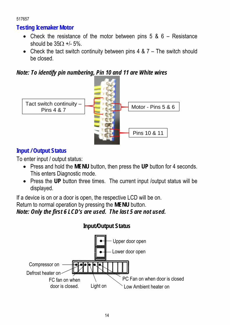
Testing Icemaker Motor Check the resistance of the motor between pins 5 & 6 – Resistance
should be 35 +/- 5%. Check the tact switch continuity between pins 4 & 7 – The switch should
be closed. Note: To identify pin numbering, Pin 10 and 11 are White wires
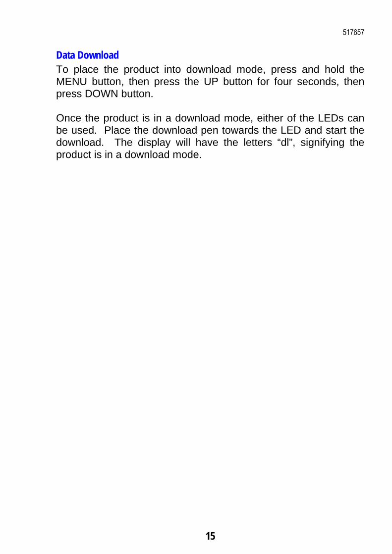
Input / Output Status To enter input / output status:
Press and hold the MENU button, then press the UP button for 4 seconds. This enters Diagnostic mode.
Press the UP button three times. The current input /output status will be displayed.
If a device is on or a door is open, the respective LCD will be on. Return to normal operation by pressing the MENU button. Note: Only the first 6 LCD’s are used. The last 5 are not used.
Input/Output Status
Light on Low Ambient heater on
Defrost heater on FC fan on when door is closed.
Compressor on
PC Fan on when door is closed
Upper door open
Pins 10 & 11
Motor - Pins 5 & 6 Tact switch continuity –
Pins 4 & 7
Lower door open
517657
15
Data Download To place the product into download mode, press and hold the MENU button, then press the UP button for four seconds, then press DOWN button. Once the product is in a download mode, either of the LEDs can be used. Place the download pen towards the LED and start the download. The display will have the letters “dl”, signifying the product is in a download mode.

517657
16
Wiring Diagram – VCC Compressor

517657
17