5.14 Transmission Line Safety - California Energy Commission · 5.14 Transmission Line Safety and...
13
5.14 Transmission Line Safety and Nuisance Blythe Solar Power Project 5.14-1 August 2009 5.14 Transmission Line Safety and Nuisance This section discusses safety and nuisance issues associated with the transmission system improvements that will interconnect the Blythe Solar Power Project (BSSP or Project) with the SCE regional transmission system. This section discusses the general aspects of the transmission interconnection and also addresses electric and magnetic fields changes that would occur as a result of the Project. The transmission line safety and nuisance evaluation presented in the following pages is intended to support compliance both by the California Energy Commission (CEC) with the requirements of the California Environmental Quality Act (CEQA), and by the Bureau of Land Management (BLM) with the requirements of the National Environmental Policy Act (NEPA). The two agencies are conducting a joint review of the Project and a combined CEQA/NEPA document will be prepared. Summary Project’s transmission line safety and nuisance impacts would be less than significant. Analyses indicate that neither Project construction nor operation would result in significant increases in electromagnetic fields (EMF) levels or audible noise. Because the Project transmission system will conform to applicable California Public Utilities Commission (CPUC) and other regulatory requirements, induced current and voltage are unlikely to lead to hazardous electrical shocks. Corona caused by power lines can cause interference with radio and television reception. Corona typically becomes a design concern for transmission lines with voltages of 345 kV and above. The Project will be connected at 500 kV, but because it will use a bundled connector design, no corona-related design issues are expected. Due to the remoteness of the Project electric transmission facilities, no adverse effects to local communication networks are anticipated. Project design and construction will adhere to standards and procedures that minimize the likelihood of interference with aircraft communications or avionics. 5.14.1 LORS Compliance This section provides a list of applicable LORS that apply to the proposed transmission system improvements. The Project will comply with the applicable LORS during construction and operation. 5.14.1.1 Design and Construction Table 5.14-1 lists the applicable LORS for the design and construction of the proposed transmission system improvements. Table 5.14-1 Summary of Applicable Transmission System Design and Construction LORS LORS Applicability Where Discussed in AFC Rules for Underground Electric Line Construction: California Public Utilities Commission (CPUC), General Order (GO)-128 Covers required clearances, grounding techniques, maintenance, and inspection requirements. Section 5.14.1
-
Upload
phungkhanh -
Category
Documents
-
view
227 -
download
1
Transcript of 5.14 Transmission Line Safety - California Energy Commission · 5.14 Transmission Line Safety and...

5.14 Transmission Line Safety and Nuisance
Blythe Solar Power Project 5.14-1 August 2009
5.14 Transmission Line Safety and Nuisance
This section discusses safety and nuisance issues associated with the transmission system improvements that will interconnect the Blythe Solar Power Project (BSSP or Project) with the SCE regional transmission system. This section discusses the general aspects of the transmission interconnection and also addresses electric and magnetic fields changes that would occur as a result of the Project.
The transmission line safety and nuisance evaluation presented in the following pages is intended to support compliance both by the California Energy Commission (CEC) with the requirements of the California Environmental Quality Act (CEQA), and by the Bureau of Land Management (BLM) with the requirements of the National Environmental Policy Act (NEPA). The two agencies are conducting a joint review of the Project and a combined CEQA/NEPA document will be prepared.
Summary
Project’s transmission line safety and nuisance impacts would be less than significant. Analyses indicate that neither Project construction nor operation would result in significant increases in electromagnetic fields (EMF) levels or audible noise. Because the Project transmission system will conform to applicable California Public Utilities Commission (CPUC) and other regulatory requirements, induced current and voltage are unlikely to lead to hazardous electrical shocks. Corona caused by power lines can cause interference with radio and television reception. Corona typically becomes a design concern for transmission lines with voltages of 345 kV and above. The Project will be connected at 500 kV, but because it will use a bundled connector design, no corona-related design issues are expected. Due to the remoteness of the Project electric transmission facilities, no adverse effects to local communication networks are anticipated. Project design and construction will adhere to standards and procedures that minimize the likelihood of interference with aircraft communications or avionics.
5.14.1 LORS Compliance
This section provides a list of applicable LORS that apply to the proposed transmission system improvements. The Project will comply with the applicable LORS during construction and operation.
5.14.1.1 Design and Construction
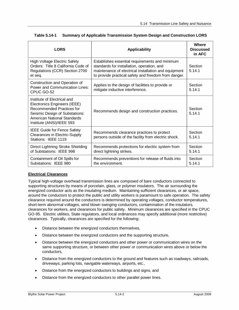
Table 5.14-1 lists the applicable LORS for the design and construction of the proposed transmission system improvements.
Table 5.14-1 Summary of Applicable Transmission System Design and Construction LORS
LORS Applicability Where
Discussed in AFC
Rules for Underground Electric Line Construction: California Public Utilities Commission (CPUC), General Order (GO)-128
Covers required clearances, grounding techniques, maintenance, and inspection requirements.
Section 5.14.1
5.14 Transmission Line Safety and Nuisance
Blythe Solar Power Project 5.14-2 August 2009
Table 5.14-1 Summary of Applicable Transmission System Design and Construction LORS
LORS Applicability Where
Discussed in AFC
High Voltage Electric Safety Orders: Title 8 California Code of Regulations (CCR) Section 2700 et seq.
Establishes essential requirements and minimum standards for installation, operation, and maintenance of electrical installation and equipment to provide practical safety and freedom from danger.
Section 5.14.1
Construction and Operation of Power and Communication Lines: CPUC GO-52
Applies to the design of facilities to provide or mitigate inductive interference.
Section 5.14.1
Institute of Electrical and Electronics Engineers (IEEE) Recommended Practices for Seismic Design of Substations: American National Standards Institute (ANSI)/IEEE 593
Recommends design and construction practices. Section 5.14.1
IEEE Guide for Fence Safety Clearances in Electric-Supply Stations: IEEE 1119
Recommends clearance practices to protect persons outside of the facility from electric shock.
Section 5.14.1
Direct Lightning Stroke Shielding of Substations: IEEE 998
Recommends protections for electric system from direct lightning strikes.
Section 5.14.1
Containment of Oil Spills for Substations: IEEE 980
Recommends preventions for release of fluids into the environment.
Section 5.14.1
Electrical Clearances
Typical high-voltage overhead transmission lines are composed of bare conductors connected to supporting structures by means of porcelain, glass, or polymer insulators. The air surrounding the energized conductor acts as the insulating medium. Maintaining sufficient clearances, or air space, around the conductors to protect the public and utility workers is paramount to safe operation. The safety clearance required around the conductors is determined by operating voltages, conductor temperatures, short-term abnormal voltages, wind blown swinging conductors, contamination of the insulators, clearances for workers, and clearances for public safety. Minimum clearances are specified in the CPUC GO-95. Electric utilities, State regulators, and local ordinances may specify additional (more restrictive) clearances. Typically, clearances are specified for the following:
Distance between the energized conductors themselves,
Distance between the energized conductors and the supporting structure,
Distance between the energized conductors and other power or communication wires on the same supporting structure, or between other power or communication wires above or below the conductors,
Distance from the energized conductors to the ground and features such as roadways, railroads, driveways, parking lots, navigable waterways, airports, etc.,
Distance from the energized conductors to buildings and signs, and
Distance from the energized conductors to other parallel power lines.

5.14 Transmission Line Safety and Nuisance
Blythe Solar Power Project 5.14-3 August 2009
Substation/Switchyard Design
The Project anticipates a direct interconnection with the SCE transmission system at SCE’s planned 500-kilovolt (kV) Colorado River substation southwest of the Project site. The layout of the Project power block switchyard (each of the four 250-megwatt units will have their own), is shown in Figure 2-5 in Section 2.0, Project Description. Figure 2-9 is a single line diagram of the planned central switchyard, the point of origin of the 500-kV gen-tie line. All facilities will be constructed in conformance with the applicable LORS, specifically IEEE 1127-1998, which deals with substation and switchyard design in order to minimize switchyard noise and electromagnetic fields (EMF). The onsite switchyards will have perimeter fencing to keep pedestrian traffic away from live equipment and from exposure to EMF.
5.14.1.2 Aviation Safety
Table 5.14-2 lists the applicable LORS regarding aviation safety with respect to the proposed transmission system improvements.
Table 5.14-2 Summary of Applicable Transmission System Aviation Safety LORS
LORS Applicability Where Discussed
in AFC
Objects Affecting the Navigable Air Space: Title 14 Code of Federal Regulations (CFR) Part 77
Describes the criteria used to determine the need for a Federal Aviation Administration (FAA) “Notice of Proposed Construction or Alteration” in cases of potential obstruction hazards.
Section 5.14.3
Proposed Construction and/or Alteration of Objects that May Affect the Navigation Space: FAA Advisory Circular No. 70/7460-1G
Addresses the need to file the “Notice of Proposed Construction or Alteration” (Form 7460) with the FAA in cases of potential for an obstruction hazard.
Section 5.14.3
5.14.1.3 Interference with Radio Frequency Communication
Table 5.14-3 lists the applicable LORS regarding radio frequency communications with respect to the proposed transmission system improvements.
Table 5.14-3 Summary of Applicable Transmission System Radio Frequency Communication LORS
LORS Applicability Where
Discussed in AFC
Federal Communications Commission (FCC): Title 47 CFR Section 15.2524,
Prohibits operation of devices that can interfere with radio-frequency communication.
Section 5.14.3
CPUC GO-52 Governs the construction and operation of power and communications lines to prevent or mitigate interference.
Section 5.14.3
CEC staff, Radio Interference and Television Interference(RI-TVI) Criteria (Kern River Cogeneration) Project 82-AFC-2, Final Decision, Compliance Plan 13-7
Prescribes the CEC’s RI-TVI mitigation requirements, developed and adopted by the CEC in past siting cases.
Section 5.14.3
5.14 Transmission Line Safety and Nuisance
Blythe Solar Power Project 5.14-4 August 2009
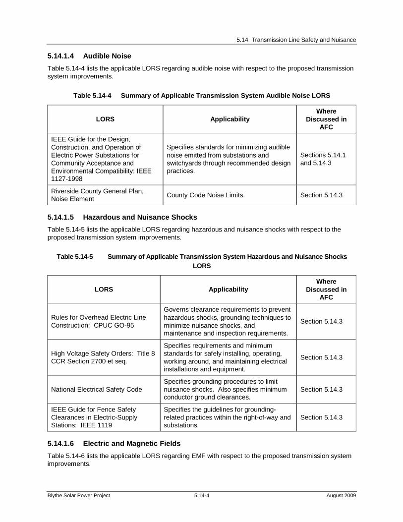
5.14.1.4 Audible Noise
Table 5.14-4 lists the applicable LORS regarding audible noise with respect to the proposed transmission system improvements.
Table 5.14-4 Summary of Applicable Transmission System Audible Noise LORS
LORS Applicability Where
Discussed in AFC
IEEE Guide for the Design, Construction, and Operation of Electric Power Substations for Community Acceptance and Environmental Compatibility: IEEE 1127-1998
Specifies standards for minimizing audible noise emitted from substations and switchyards through recommended design practices.
Sections 5.14.1 and 5.14.3
Riverside County General Plan, Noise Element
County Code Noise Limits. Section 5.14.3
5.14.1.5 Hazardous and Nuisance Shocks
Table 5.14-5 lists the applicable LORS regarding hazardous and nuisance shocks with respect to the proposed transmission system improvements.
Table 5.14-5 Summary of Applicable Transmission System Hazardous and Nuisance Shocks LORS
LORS Applicability Where
Discussed in AFC
Rules for Overhead Electric Line Construction: CPUC GO-95
Governs clearance requirements to prevent hazardous shocks, grounding techniques to minimize nuisance shocks, and maintenance and inspection requirements.
Section 5.14.3
High Voltage Safety Orders: Title 8 CCR Section 2700 et seq.
Specifies requirements and minimum standards for safely installing, operating, working around, and maintaining electrical installations and equipment.
Section 5.14.3
National Electrical Safety Code Specifies grounding procedures to limit nuisance shocks. Also specifies minimum conductor ground clearances.
Section 5.14.3
IEEE Guide for Fence Safety Clearances in Electric-Supply Stations: IEEE 1119
Specifies the guidelines for grounding-related practices within the right-of-way and substations.
Section 5.14.3
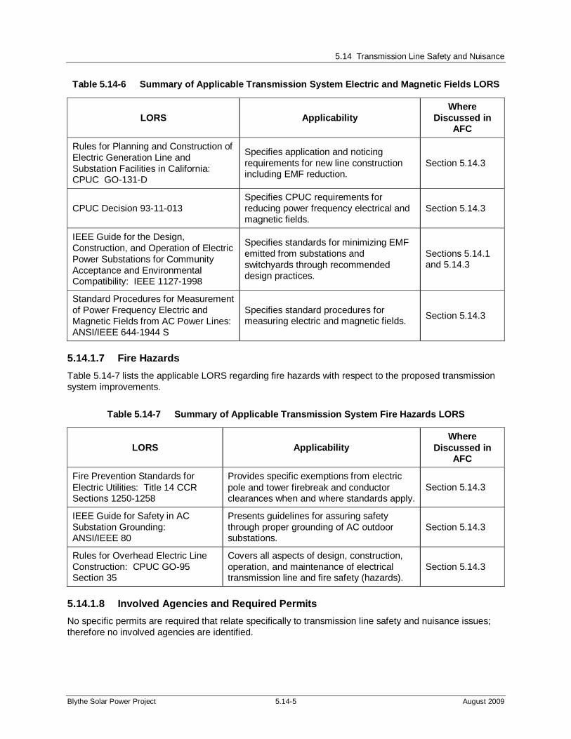
5.14.1.6 Electric and Magnetic Fields
Table 5.14-6 lists the applicable LORS regarding EMF with respect to the proposed transmission system improvements.
5.14 Transmission Line Safety and Nuisance
Blythe Solar Power Project 5.14-5 August 2009
Table 5.14-6 Summary of Applicable Transmission System Electric and Magnetic Fields LORS
LORS Applicability Where
Discussed in AFC
Rules for Planning and Construction of Electric Generation Line and Substation Facilities in California: CPUC GO-131-D
Specifies application and noticing requirements for new line construction including EMF reduction.
Section 5.14.3
CPUC Decision 93-11-013 Specifies CPUC requirements for reducing power frequency electrical and magnetic fields.
Section 5.14.3
IEEE Guide for the Design, Construction, and Operation of Electric Power Substations for Community Acceptance and Environmental Compatibility: IEEE 1127-1998
Specifies standards for minimizing EMF emitted from substations and switchyards through recommended design practices.
Sections 5.14.1 and 5.14.3
Standard Procedures for Measurement of Power Frequency Electric and Magnetic Fields from AC Power Lines: ANSI/IEEE 644-1944 S
Specifies standard procedures for measuring electric and magnetic fields.
Section 5.14.3
5.14.1.7 Fire Hazards
Table 5.14-7 lists the applicable LORS regarding fire hazards with respect to the proposed transmission system improvements.
Table 5.14-7 Summary of Applicable Transmission System Fire Hazards LORS
LORS Applicability Where
Discussed in AFC
Fire Prevention Standards for Electric Utilities: Title 14 CCR Sections 1250-1258
Provides specific exemptions from electric pole and tower firebreak and conductor clearances when and where standards apply.
Section 5.14.3
IEEE Guide for Safety in AC Substation Grounding: ANSI/IEEE 80
Presents guidelines for assuring safety through proper grounding of AC outdoor substations.
Section 5.14.3
Rules for Overhead Electric Line Construction: CPUC GO-95 Section 35
Covers all aspects of design, construction, operation, and maintenance of electrical transmission line and fire safety (hazards).
Section 5.14.3
5.14.1.8 Involved Agencies and Required Permits
No specific permits are required that relate specifically to transmission line safety and nuisance issues; therefore no involved agencies are identified.

5.14 Transmission Line Safety and Nuisance
Blythe Solar Power Project 5.14-6 August 2009
5.14.2 Affected Environment
The affected environment related to the transmission system is considered to be the area along the proposed new transmission line from the central switchyard at the BSPP facility site to the Project’s interconnection point with the SCE transmission system at SCE’s planned Colorado River Substation, whose location was recently finalized about five miles southwest of the Project site. Figure 2-4 in Section 2.0, Project Description, shows the location of the central switchyard and the transmission line connecting the Project’s switchyard to the planned Colorado River Substation, although the Project transmission line route has not been finalized.
5.14.3 Environmental Impacts
5.14.3.1 Aviation Safety
The Project is located one mile north of an active airport (in Blythe). Due to this proximity, height restrictions were evaluated for Project structures that would need to be located within this distance from the airport. The tallest structures on the site will be the four cooling towers at 120 feet. The cooling towers are sufficiently removed from the airport that this height is not an issue. The Project also involves a 500-kV (kV) single circuit transmission line using monopole structures that starts northwest of the airport is expected to head south to the west of the airport and eventually turning west and south to reach the Colorado River substation. The Project will install monopoles of a sufficiently low height to ensure that the Project meets the height restrictions in the area of concern near the airport. As discussed in Section 5.13, Traffic and Transportation, analysis showed that there is a relatively short transmission line section (less than one mile) for which a height restriction of 90 feet will be required (and will be implemented). No significant aviation safety impacts would be expected, but the Project will submit to the Federal Aviation Administration (FAA) a “Notice of Proposed Construction and Alteration” (Form 7460) to the FAA consistent with the advance notice requirement contained in FAA regulations.
5.14.3.2 Radio Frequency Communications
Transmission line-related radio frequency interference is one of the indirect effects of transmission line operation and is produced by the physical interactions of line electric fields. Such interference is due to the radio noise produced by the action of the electric fields on the surface of the energized conductor. The process involved is known as corona discharge and can occur within gaps between the conductor and insulators or metal fittings. Since the level of interference depends on factors such as line voltage, distance from the line to the receiving device, orientation of the antenna, signal level, line configuration and weather conditions, maximum interference levels are not specified as design criteria for modern transmission lines. The level of any such interference usually depends on the magnitude of the electric fields involved and the distance from the line. However, the potential for such impacts is minimized by reducing the line electric fields and locating the line away from inhabited areas.
The potential for such corona-related interference is usually of concern for lines of 345 kV and above. The BSPP transmission line will operate at 500 kV and will be designed in accordance with standard utility practices to reduce the electric field at energized surfaces to acceptable levels. Each transmission line circuit consists of three phases. Each phase conductor utilized will be bundled - two or more sub-conductors separated by 18 to 22 inches to make up one phase conductor - specifically to reduce electric fields at the conductor surface. In addition, electric field mitigation devices called corona rings will be mounted at conductor-hardware interface points at the end of the insulators to reduce the field levels at those locations. Radio frequency interference is not expected to be a concern during operation of the line.

5.14 Transmission Line Safety and Nuisance
Blythe Solar Power Project 5.14-7 August 2009
5.14.3.3 Audible Noise
Corona may also produce audible noise from a transmission line. Corona is a function of the voltage of the line, the equivalent diameter of the conductor, and the condition of the conductor and suspension hardware. The electric field gradient is the rate at which the electric field changes and is directly related to the line voltage.
The electric field gradient is greatest near the surface of the conductor. Large-diameter conductors have lower electric field gradients at the conductor surface and, hence, lower corona than smaller conductors, everything else being equal. Bundled conductors have a larger equivalent diameter that further mitigates field gradients. Also, irregularities (such as nicks and scrapes on the conductor surface) or sharp edges on suspension hardware concentrate the electric field at these locations and, thus, increase corona at these spots. Similarly, contamination on the conductor surface can cause irregularities that are a source for corona. Raindrops, snow, fog, and condensation are also sources of irregularities. Corona typically becomes a design concern for transmission lines having voltages of 345 kV and above. Since the Project will be connected at 500 kV and will utilize a bundled conductor design, it is expected that no corona-related design issues will be encountered. Additionally, research by the Electric Power Research Institute has shown that the fair-weather audible noise from modern transmission lines to be generally indistinguishable from background noise at the edge of a right-of-way of one hundred feet or more.
An additional source of audible noise is transformer hum caused by extension and contraction of the core laminations when magnetized. On the facility site, generator step-up transformer (GSU) hum is insignificant in comparison to plant operation and therefore, will not add any appreciable audible noise to the noise levels discussed in Section 5.8, Noise.
5.14.3.4 Electrical Effects
The electrical effects of high-voltage transmission lines fall into two broad categories: corona effects and field effects. Corona is the ionization of the air at the surface of the energized conductor and suspension hardware due to very high electric field strength. Corona effects were described above and are generally considered in the context of audible noise and radio frequency interference. Field effects are the voltages and currents that may be induced in nearby conducting objects. A transmission line's inherent EMF causes these effects.
Induced Current and Voltages
Hazardous shocks are those that could result from direct or indirect contact between an individual and the energized line, whether overhead or underground. Such shocks are capable of serious physiological harm or death and remain a driving force in the design and operation of transmission and other high-voltage lines.
A conducting object, such as a vehicle or person in an electric field, will experience induced voltages and currents. The strength of the induced current will depend on the electric field strength, the size and shape of the conducting object, and the object-to-ground resistance. When a conducting object is isolated from the ground and a grounded person touches the object, a perceptible current or shock may occur as the current flows to ground and could be characterized as a nuisance shock. Proper design standards will be implemented to prevent hazardous and nuisance shocks by ensuring that metallic objects on or near the right-of-way are grounded and that sufficient clearances are provided at roadways and parking lots to keep electric fields at these locations low enough to prevent vehicle short-circuit currents from exceeding 5 milliamperes.
The Project’s transmission interconnection will be constructed in conformance with CPUC GO-95 and Title 8 CCR 2700 requirements. These regulations require sufficient grounding to ensure that hazardous

5.14 Transmission Line Safety and Nuisance
Blythe Solar Power Project 5.14-8 August 2009
shocks do not occur. Therefore, hazardous shocks are unlikely as a result of Project construction, operation, or maintenance. A shield wire will be installed as a feature of the Project. Additionally, shocks are effectively minimized through grounding procedures specified in the National Electrical Safety Code and the joint guidelines of the ANSI and the IEEE.
Electric and Magnetic Fields
Circulating currents, such as found in the energized components of electrical motors, home wiring, lighting, and all other electrical appliances, produce electric and magnetic fields, commonly referred to as EMF. The EMF produced by the alternating current electrical power system in the United States has a frequency of 60 hertz (Hz), meaning that the intensity and orientation of the field changes 60 times per second.
Electric fields around transmission lines are produced by electrical charges on the energized conductor. Electric field strength is directly proportional to the line's voltage; that is, increased voltage produces a higher electric field. At a given distance from the transmission line conductor, the electric field is inversely proportional to the distance from the conductors, so that the electric field strength declines as the distance from the conductor increases. The strength of the electric field is measured in units of kV per meter (kV/m). The electric field around a transmission line remains steady and is not affected by the common daily and seasonal fluctuations in usage of electricity by customers.
Magnetic fields around transmission lines are produced by the level of current flow through the conductors, measured in amperes. The magnetic field strength is also directly proportional to the current; that is, increased amperes produce a stronger magnetic field. The magnetic field is inversely proportional to the distance from the conductors, and thus, like the electric field, the magnetic field strength declines as the distance from the conductor increases. Magnetic fields are expressed in units of milligauss (mG). The current and, therefore the magnetic field around a transmission line, fluctuate daily and seasonally as the usage of electricity varies.
Considerable research has been conducted over the last thirty years on the possible biological effects and human health effects from EMF. This research has produced many studies that offer no uniform conclusions about whether long-term exposure to EMF is harmful or not. In the absence of conclusive evidence, some states, California in particular, have chosen not to specify maximum acceptable levels of EMF. Instead, California mandates a program of prudent avoidance whereby EMF exposure to the public would be minimized by encouraging electric utilities to use low-cost techniques to reduce the levels of EMF.
EMF Assumptions. It is important that any discussion of EMF include the assumptions used to calculate the values and to remember that EMF in the vicinity of power lines varies based on a variety of factors including, line design, the presence of other lines in the right of way (ROW), line loading, and distance from the line. The electric field depends upon the line voltage and 500 kV has been used nominally throughout this Application for Certification as SCE utilizes the nominal voltage of 500 kV. The use of 500 kV in this document is consistent with the industry use of 500 kV to describe the nominal standard voltage for this class of system. The magnetic field is proportional to the line current (amperes), which varies based on the interconnected power system loading, and the power output of the generating facility as output changes to meet increases or decreases in demand for electric power or as the solar energy varies. The line loading values were based on the nominal load.
The arrangement of the transmission lines in the ROW is another important consideration for the field calculation. The Project interconnection will utilize a new ROW; therefore, no other lines are considered in this study. The phase arrangement of each line has been entered into the model used for the field calculation. The phase arrangement is indicated in the conceptual pole configuration in Figure 5.14-1
5.14 Transmission Line Safety and Nuisance
Blythe Solar Power Project 5.14-9 August 2009
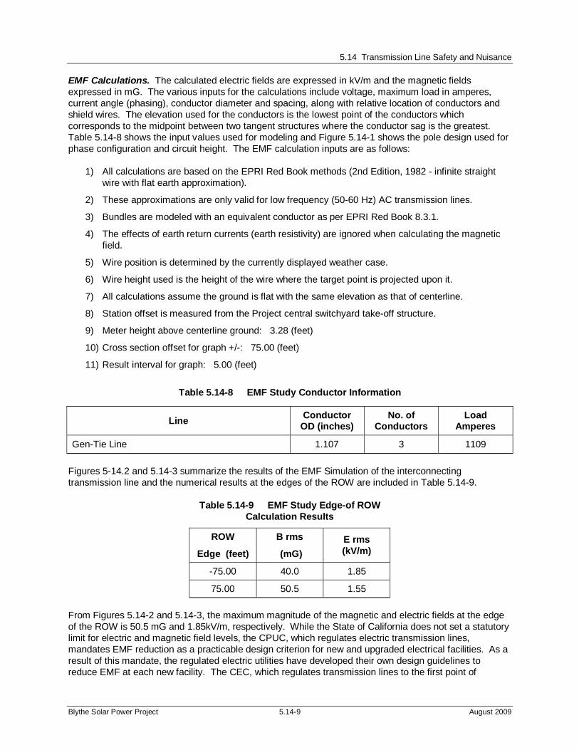
EMF Calculations. The calculated electric fields are expressed in kV/m and the magnetic fields expressed in mG. The various inputs for the calculations include voltage, maximum load in amperes, current angle (phasing), conductor diameter and spacing, along with relative location of conductors and shield wires. The elevation used for the conductors is the lowest point of the conductors which corresponds to the midpoint between two tangent structures where the conductor sag is the greatest. Table 5.14-8 shows the input values used for modeling and Figure 5.14-1 shows the pole design used for phase configuration and circuit height. The EMF calculation inputs are as follows:
1) All calculations are based on the EPRI Red Book methods (2nd Edition, 1982 - infinite straight wire with flat earth approximation).
2) These approximations are only valid for low frequency (50-60 Hz) AC transmission lines.
3) Bundles are modeled with an equivalent conductor as per EPRI Red Book 8.3.1.
4) The effects of earth return currents (earth resistivity) are ignored when calculating the magnetic field.
5) Wire position is determined by the currently displayed weather case.
6) Wire height used is the height of the wire where the target point is projected upon it.
7) All calculations assume the ground is flat with the same elevation as that of centerline.
8) Station offset is measured from the Project central switchyard take-off structure.
9) Meter height above centerline ground: 3.28 (feet)
10) Cross section offset for graph +/-: 75.00 (feet)
11) Result interval for graph: 5.00 (feet)
Table 5.14-8 EMF Study Conductor Information
Line Conductor
OD (inches) No. of
Conductors Load
Amperes
Gen-Tie Line 1.107 3 1109
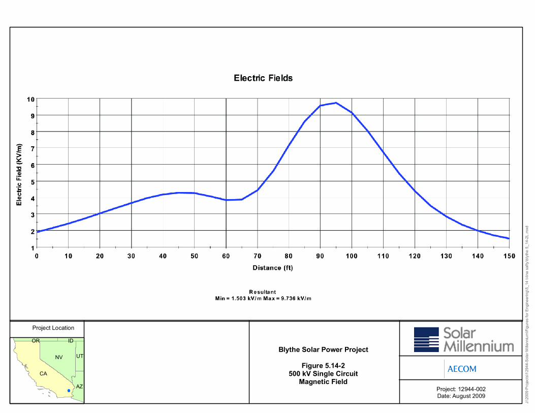
Figures 5-14.2 and 5.14-3 summarize the results of the EMF Simulation of the interconnecting transmission line and the numerical results at the edges of the ROW are included in Table 5.14-9.
Table 5.14-9 EMF Study Edge-of ROW Calculation Results
ROW
Edge (feet)
B rms
(mG)
E rms (kV/m)
-75.00 40.0 1.85
75.00 50.5 1.55
From Figures 5.14-2 and 5.14-3, the maximum magnitude of the magnetic and electric fields at the edge of the ROW is 50.5 mG and 1.85kV/m, respectively. While the State of California does not set a statutory limit for electric and magnetic field levels, the CPUC, which regulates electric transmission lines, mandates EMF reduction as a practicable design criterion for new and upgraded electrical facilities. As a result of this mandate, the regulated electric utilities have developed their own design guidelines to reduce EMF at each new facility. The CEC, which regulates transmission lines to the first point of

5.14 Transmission Line Safety and Nuisance
Blythe Solar Power Project 5.14-10 August 2009
connection, requires generators to follow the existing guidelines that are in use by local electric utilities or transmission-system owners.
In keeping with the goal of EMF reduction, the interconnections of the Blythe Project will be designed and constructed using the principles outlined in the directives of the CPUC by developing design procedures compliant with Decision 93-11-013 and GO-95, -128, and -131-D.
The primary techniques for reducing EMF anywhere along a transmission line are to:
Increase the pole height for overhead design,
Minimize the current on the line, and
Optimize the orientation of the line phases.
According to IEEE 1127-1998, EMF at the fence line of substations and switchyards is insignificant with respect to the incoming transmission lines and therefore was not considered in the EMF study. The incoming transmission lines will be designed to maintain minimum ground clearances until within the Project switching station and Colorado River substation fence lines and thus were included in the study.
Anticipated EMF levels are typical for the Project as designed. If required, the pre- and post-interconnection verification measurements could be made consistent with IEEE guidelines
5.14.3.5 Fire Hazards
The proposed 500-kV transmission interconnection lines will be designed, constructed, and maintained in accordance with the CPUC’s GO-95, which establishes clearances from other man-made and natural structures to reduce/avoid fire hazards. The Project will maintain the onsite portions of the transmission line route and immediate area in accordance with existing regulations and accepted industry practices that will include identification and abatement of any fire hazards. The offsite portions of the transmission line will be owned and operated by SCE and the line and immediate area also will be maintained in accordance with applicable requirements and standard good practices that include fire protection.
5.14.4 Mitigation Measures
No significant transmission line-related impacts were identified as a result of the Project studies. The Project will be designed, constructed, operated, and maintained in accordance with the applicable LORS and to minimize EMF at the edges of the ROW. Impacts will be less than significant with Project implementation as described in this section (e.g., insulators and hardware selected to minimize corona noise; pre- and post-Project noise surveys performed to document ambient condition change caused by the line, and procedures to investigate and resolve interference complaints). No additional mitigation is required. However, should additional currently unforeseen issues arise; they will be addressed to ensure that impacts remain less than significant.

Project: 12944-002Date: August 2009
Blythe Solar Power ProjectFigure 5.14-1
500 kV Single CircuitStructure Elevation
Project Location
J:\20
09 Pr
ojects
\1294
4-Sola
r Mille
nnium
\Figu
res fo
r Eng
ineeri
ng\5_
14 t-l
ine sa
fty\bl
ythe-5
_14-1
.mxd
CA
NV
AZ
UT
OR ID
Project: 12944-002Date: August 2009
Blythe Solar Power ProjectFigure 5.14-2
500 kV Single CircuitMagnetic Field
Project Location
J:\20
09 Pr
ojects
\1294
4-Sola
r Mille
nnium
\Figu
res fo
r Eng
ineeri
ng\5_
14 t-l
ine sa
fty\bl
ythe 5
_14-2
L.mxd
CA
NV
AZ
UT
OR ID

Project: 12944-002Date: August 2009
Blythe Solar Power ProjectFigure 5.14-3
500 kV Single CircuitElectric Field
Project Location
J:\20
09 Pr
ojects
\1294
4-Sola
r Mille
nnium
\Figu
res fo
r Eng
ineeri
ng\5_
14 t-l
ine sa
fty\Bl
ythe-5
_14-3
L.mxd
CA
NV
AZ
UT
OR ID