5.1 5 ComputerOrganization Foundations of Computer Science Cengage Learning.
71
5.1 5 5 Computer Computer Organization Organization Foundations of Computer Science Cengage Learning
-
Upload
esther-phelps -
Category
Documents
-
view
217 -
download
0
Transcript of 5.1 5 ComputerOrganization Foundations of Computer Science Cengage Learning.

5.1
55ComputerComputerOrganizationOrganization
Foundations of Computer Science Cengage Learning
5.2
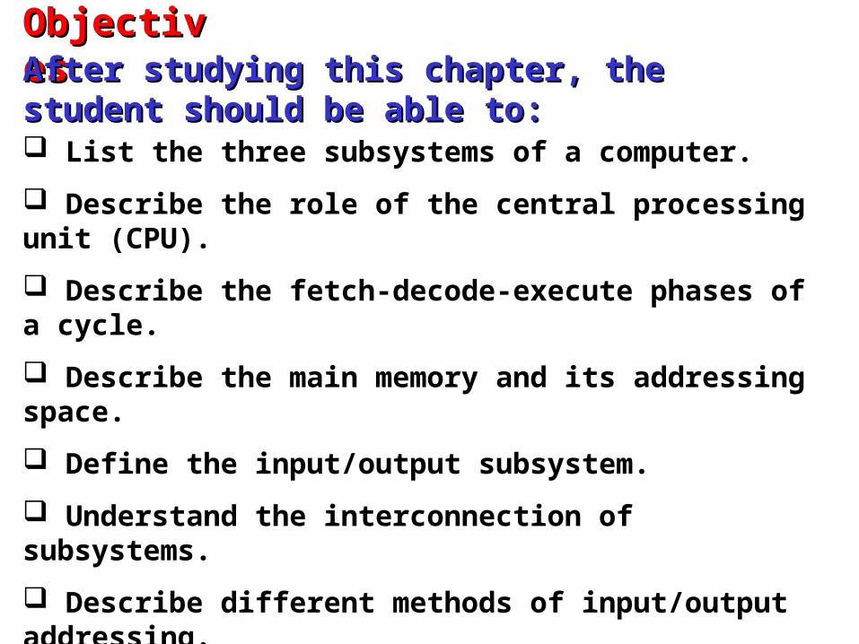
List the three subsystems of a computer.
Describe the role of the central processing unit (CPU).
Describe the fetch-decode-execute phases of a cycle.
Describe the main memory and its addressing space.
Define the input/output subsystem.
Understand the interconnection of subsystems.
Describe different methods of input/output addressing.
Distinguish the two major trends in the design of computers.
Understand how computer throughput can be improved using pipelining and parallel processing.
ObjectivesObjectivesAfter studying this chapter, the student should be able After studying this chapter, the student should be able to:to:

5.3
We can divide the parts that make up a computer into We can divide the parts that make up a computer into three broad categories or subsystem: thethree broad categories or subsystem: the central central processing unit (CPU)processing unit (CPU), the, the main memory main memory and the and theinput/output subsysteminput/output subsystem. .
Figure 5.1 Computer hardware (subsystems)
5.4
5-1 CENTRAL PROCESSING UNIT5-1 CENTRAL PROCESSING UNIT
The The central processing unit (CPU)central processing unit (CPU) performs performs operations on data. In most architectures it has three operations on data. In most architectures it has three parts: an parts: an arithmetic logic unit (ALU)arithmetic logic unit (ALU), a , a control unitcontrol unit and a set of and a set of registersregisters, fast storage locations., fast storage locations.
5.5
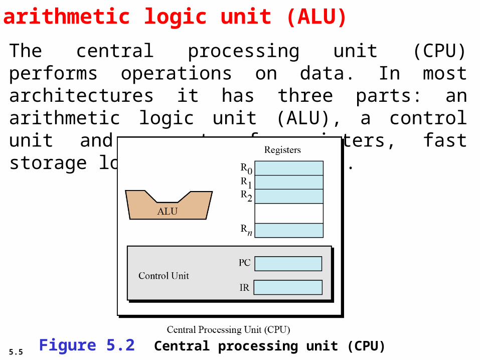
The arithmetic logic unit (ALU)
The central processing unit (CPU) performs operations on data. In most architectures it has three parts: an arithmetic logic unit (ALU), a control unit and a set of registers, fast storage locations (Figure 5.2).
Figure 5.2 Central processing unit (CPU)

5.6
Registers
Registers are fast stand-alone storage locations that hold data temporarily. Multiple registers are needed to facilitate the operation of the CPU. Some of these registers are shown in Figure 5.2.
Data registers
Instruction register
Program counter
5.7
The control unitThe third part of any CPU is the control unit. The control unit controls the operation of each subsystem. Controlling is achieved through signals sent from the control unit to other subsystems.

5.8
5-2 MAIN MEMORY5-2 MAIN MEMORY
Main memoryMain memory is the second major subsystem in a is the second major subsystem in a computer (Figure 5.3). It consists of a collection of computer (Figure 5.3). It consists of a collection of storage locations, each with a unique identifier, called storage locations, each with a unique identifier, called an an addressaddress. Data is transferred to and from memory in . Data is transferred to and from memory in groups of bits called groups of bits called wordswords. A word can be a group of 8 . A word can be a group of 8 bits, 16 bits, 32 bits or 64 bits (and growing). If the bits, 16 bits, 32 bits or 64 bits (and growing). If the word is 8 bits, it is referred to as a word is 8 bits, it is referred to as a bytebyte. The term . The term “byte” is so common in computer science that “byte” is so common in computer science that sometimes a 16-bit word is referred to as a 2-byte word, sometimes a 16-bit word is referred to as a 2-byte word, or a 32-bit word is referred to as a 4-byte word.or a 32-bit word is referred to as a 4-byte word.

5.9
Figure 5.3 Main memory
5.10
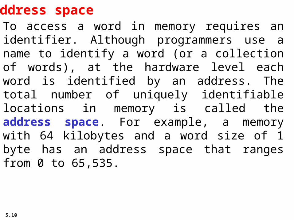
Address spaceTo access a word in memory requires an identifier. Although programmers use a name to identify a word (or a collection of words), at the hardware level each word is identified by an address. The total number of uniquely identifiable locations in memory is called the address space. For example, a memory with 64 kilobytes and a word size of 1 byte has an address space that ranges from 0 to 65,535.

5.11
Memory addresses are defined using unsignedbinary integers.
i

5.12
Example 5.1
A computer has 32 MB (megabytes) of memory. How many bits A computer has 32 MB (megabytes) of memory. How many bits are needed to address any single byte in memory?are needed to address any single byte in memory?
SolutionSolutionThe memory address space is 32 MB, or 2The memory address space is 32 MB, or 22525 (2 (255 × 2 × 22020). This ). This means that we need logmeans that we need log22 2 22525, or , or 25 bits25 bits, to address each byte., to address each byte.
Example 5.2
A computer has 128 MB of memory. Each word in this computer A computer has 128 MB of memory. Each word in this computer is eight bytes. How many bits are needed to address any single is eight bytes. How many bits are needed to address any single word in memory?word in memory?SolutionSolutionThe memory address space is 128 MB, which means 2The memory address space is 128 MB, which means 22727. . However, each word is eight (2However, each word is eight (233) bytes, which means that we ) bytes, which means that we have 2have 22424 words. This means that we need log words. This means that we need log22 2 22424, or , or 24 bits24 bits, to , to
address each word.address each word.
5.13
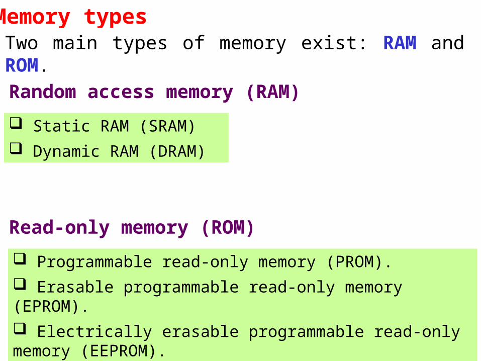
Memory typesTwo main types of memory exist: RAM and ROM.
Random access memory (RAM)
Static RAM (SRAM)
Dynamic RAM (DRAM)
Read-only memory (ROM)
Programmable read-only memory (PROM).
Erasable programmable read-only memory (EPROM).
Electrically erasable programmable read-only memory (EEPROM).

5.14
Memory hierarchyComputer users need a lot of memory, especially memory that is very fast and inexpensive. This demand is not always possible to satisfy—very fast memory is usually not cheap. A compromise needs to be made. The solution is hierarchical levels of memory.
Figure 5.4 Memory hierarchy

5.15
Cache memoryCache memory is faster than main memory, but slower than the CPU and its registers. Cache memory, which is normally small in size, is placed between the CPU and main memory (Figure 5.5).
Figure 5.5 Cache memory

5.16
5-3 INPUT/OUTPUT SUBSYSTEM5-3 INPUT/OUTPUT SUBSYSTEM
The third major subsystem in a computer is the The third major subsystem in a computer is the collection of devices referred to as the input/output collection of devices referred to as the input/output (I/O) subsystem. This subsystem allows a computer to (I/O) subsystem. This subsystem allows a computer to communicate with the outside world and to store communicate with the outside world and to store programs and data even when the power is off. programs and data even when the power is off. Input/output devices can be divided into two broad Input/output devices can be divided into two broad categories: categories: non-storagenon-storage and and storagestorage devices. devices.

5.17
Non-storage devicesNon-storage devices allow the CPU/memory to communicate with the outside world, but they cannot store information.
Keyboard and monitor
Printer

5.18
Storage devicesStorage devices, although classified as I/O devices, can store large amounts of information to be retrieved at a later time. They are cheaper than main memory, and their contents are nonvolatile—that is, not erased when the power is turned off. They are sometimes referred to as auxiliary storage devices. We can categorize them as either magnetic or optical.

5.19
Figure 5.6 A magnetic disk

5.20
Figure 5.7 A magnetic tape

5.21Figure 5.8 Creation and use of CD-ROMs
5.22

5.23
Figure 5.9 CD-ROM format

5.24
Figure 5.10 Making a CD-R

5.25
Figure 5.11 Making a CD-RW

5.26

5.27
5-4 SUBSYSTEM INTERCONNECTION5-4 SUBSYSTEM INTERCONNECTION
The previous sections outlined the characteristics of the The previous sections outlined the characteristics of the three subsystems (CPU, main memory, and I/O) in a three subsystems (CPU, main memory, and I/O) in a stand-alone computer. In this section, we explore how stand-alone computer. In this section, we explore how these three subsystems are interconnected. The these three subsystems are interconnected. The interconnection plays an important role because interconnection plays an important role because information needs to be exchanged between the three information needs to be exchanged between the three subsystems.subsystems.

5.28
Connecting CPU and memoryThe CPU and memory are normally connected by three groups of connections, each called a bus: data bus, address bus and control bus (Figure 5.12).
Figure 5.12 Connecting CPU and memory using three buses

5.29
Connecting I/O devicesI/O devices cannot be connected directly to the buses that connect the CPU and memory, because the nature of I/O devices is different from the nature of CPU and memory. I/O devices are electromechanical, magnetic, or optical devices, whereas the CPU and memory are electronic devices. I/O devices also operate at a much slower speed than the CPU/memory. There is a need for some sort of intermediaryto handle this difference. Input/output devices are therefore attached to the buses through input/output controllers or interfaces. There is one specific controller for each input/output device (Figure 5.13).

5.30
Figure 5.13 Connecting I/O devices to the buses

5.31
Figure 5.14 SCSI controller

5.32
Figure 5.15 FireWire controller
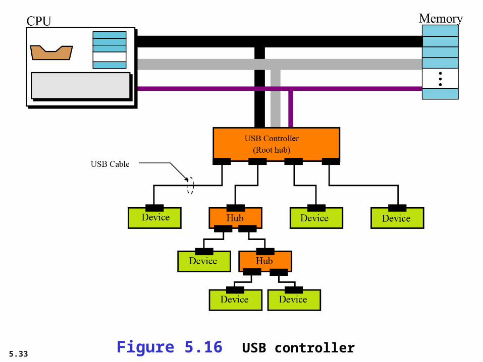
5.33Figure 5.16 USB controller
5.34
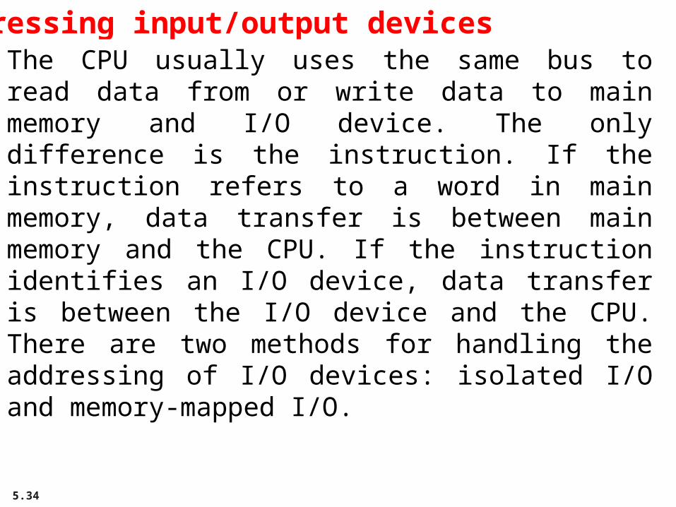
Addressing input/output devicesThe CPU usually uses the same bus to read data from or write data to main memory and I/O device. The only difference is the instruction. If the instruction refers to a word in main memory, data transfer is between main memory and the CPU. If the instruction identifies an I/O device, data transfer is between the I/O device and the CPU. There are two methods for handling the addressing of I/O devices: isolated I/O and memory-mapped I/O.
5.35
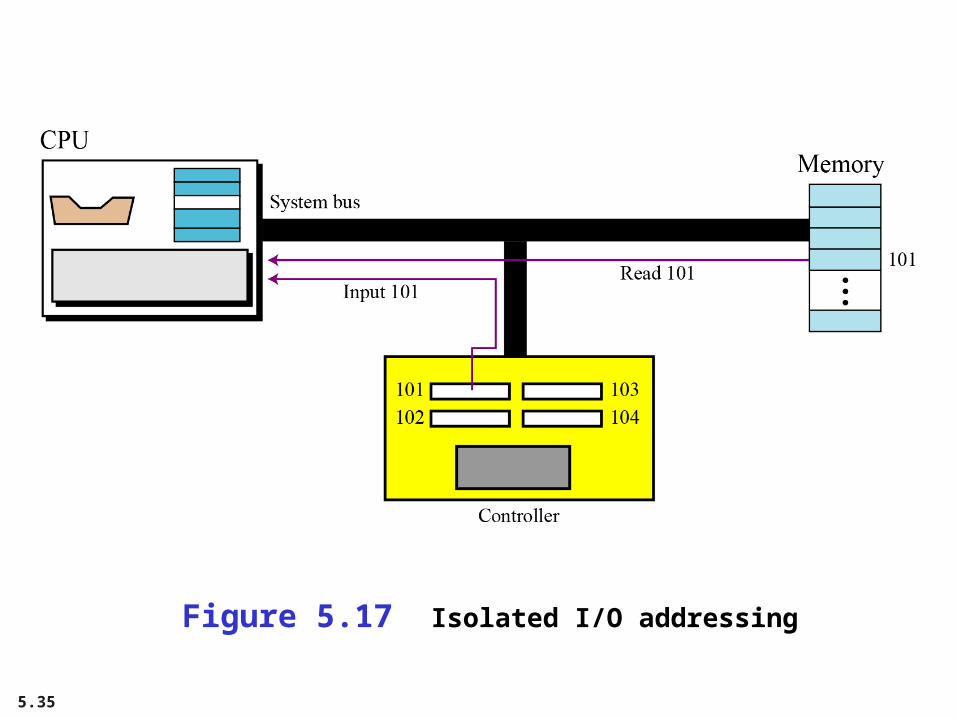
Figure 5.17 Isolated I/O addressing
5.36
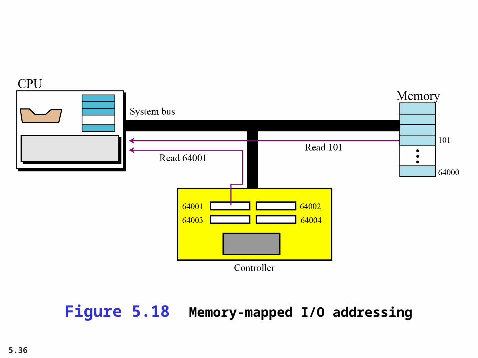
Figure 5.18 Memory-mapped I/O addressing

5.37
5-5 PROGRAM EXECUTION5-5 PROGRAM EXECUTION
Today, Today, general-purpose computersgeneral-purpose computers use a set of use a set of instructions called a instructions called a programprogram to process data. A to process data. A computer executes the program to create output data computer executes the program to create output data from input data. Both the program and the data are from input data. Both the program and the data are stored in memory.stored in memory.
At the end of this chapter we give some examples of how a hypothetical simple computer
executes a program.
i

5.38
Machine cycleThe CPU uses repeating machine cycles to execute instructions in the program, one by one, from beginning to end. A simplified cycle can consist of three phases: fetch, decode and execute (Figure 5.19).
Figure 5.19 The steps of a cycle
5.39
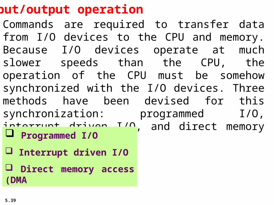
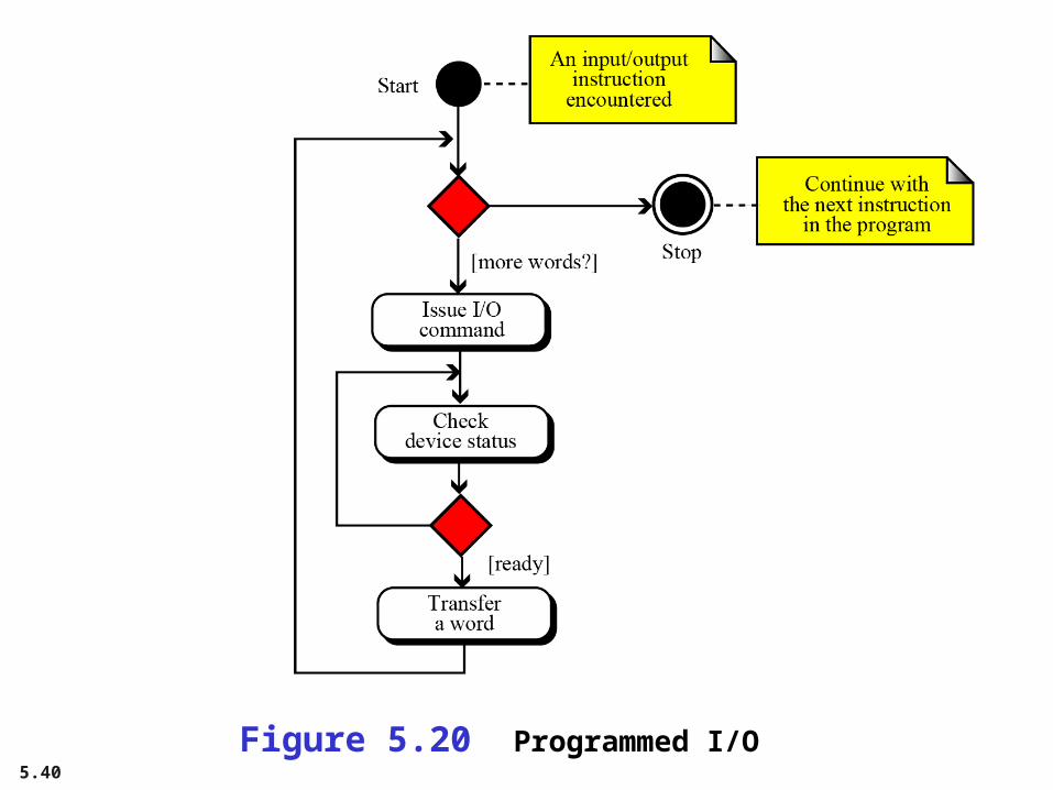
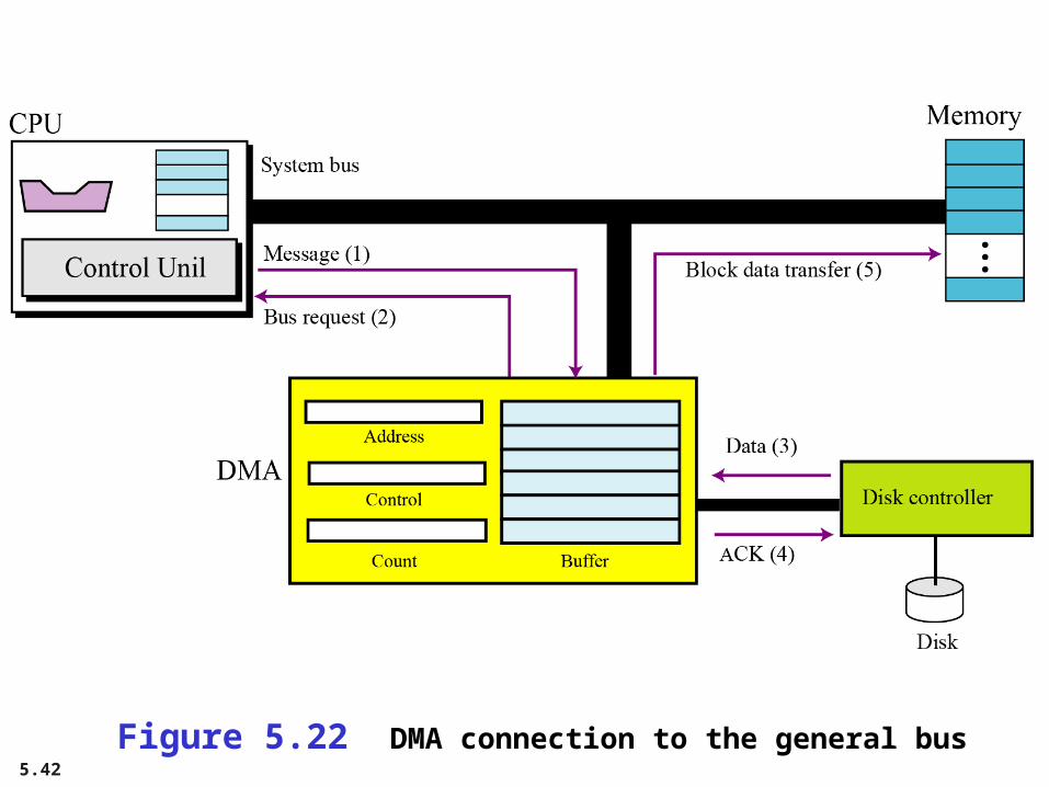
Input/output operationCommands are required to transfer data from I/O devices to the CPU and memory. Because I/O devices operate at much slower speeds than the CPU, the operation of the CPU must be somehow synchronized with the I/O devices. Three methods have been devised for this synchronization: programmed I/O, interrupt driven I/O, and direct memory access (DMA).
Programmed I/O
Interrupt driven I/O
Direct memory access (DMA
5.40
Figure 5.20 Programmed I/O

5.41
Figure 5.21 Interrupt-driven I/O
5.42
Figure 5.22 DMA connection to the general bus

5.43
Figure 5.23 DMA input/output

5.44
5-6 DIFFERENT ARCHITECTURES5-6 DIFFERENT ARCHITECTURES
The architecture and organization of computers has The architecture and organization of computers has gone through many changes in recent decades. In this gone through many changes in recent decades. In this section we discuss some common architectures and section we discuss some common architectures and organization that differ from the simple computer organization that differ from the simple computer architecture we discussed earlier.architecture we discussed earlier.

5.45
CISCCISC (pronounced sisk) stands for complex instruction set computer (CISC). The strategy behind CISC architectures is to have a large set of instructions, including complex ones. Programming CISC-based computers is easier than in other designs because there is a single instruction for both simple and complex tasks. Programmers, therefore, do not have to write a set of instructions to do a complex task.

5.46
RISCRISC (pronounced risk) stands for reduced instruction set computer. The strategy behind RISC architecture is to have a small set of instructions that do a minimum number of simple operations. Complex instructions are simulated using a subset of simple instructions. Programming in RISC is more difficult and time-consuming than in the other design, because most of the complex instructions are simulated using simple instructions.

5.47
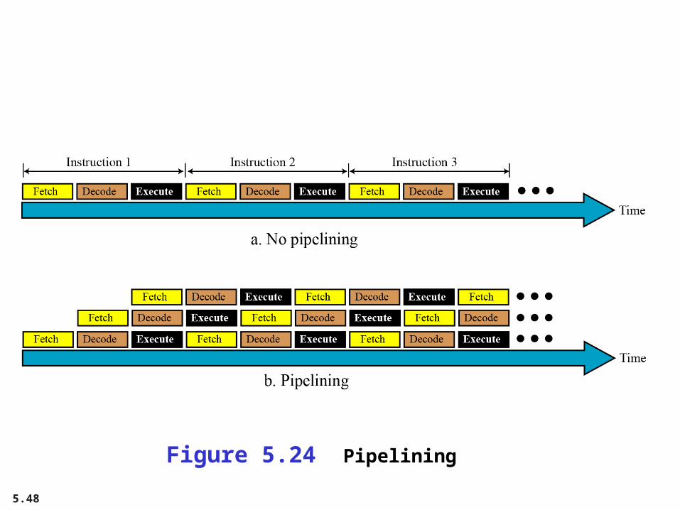
PipeliningWe have learned that a computer uses three phases, fetch, decode and execute, for each instruction. In early computers, these three phases needed to be done in series for each instruction. In other words, instruction n needs to finish all of these phases before the instruction n + 1 can start its own phases. Modern computers use a technique called pipelining to improve the throughput (the total number of instructions performed in each period of time). The idea is that if the control unit can do two or three of these phases simultaneously, the next instruction can start before the previous one is finished.
5.48
Figure 5.24 Pipelining

5.49
Parallel processingTraditionally a computer had a single control unit, a single arithmetic logic unit and a single memory unit. With the evolution in technology and the drop in the cost of computer hardware, today we can have a single computer with multiple control units, multiple arithmetic logic units and multiple memory units. This idea is referred to as parallel processing. Like pipelining, parallel processing can improvethroughput.
Figure 5.24 A taxonomy of computer organization

5.50
Figure 5.26 SISD organization

5.51
Figure 5.27 SIMD organization

5.52
Figure 5.28 MISD organization

5.53
Figure 5.29 MIMD organization

5.54
5-7 A SIMPLE COMPUTER5-7 A SIMPLE COMPUTER
To explain the architecture of computers as well as their To explain the architecture of computers as well as their instruction processing, we introduce a simple instruction processing, we introduce a simple (unrealistic) computer, as shown in Figure 5.30. Our (unrealistic) computer, as shown in Figure 5.30. Our simple computer has three components: CPU, memory simple computer has three components: CPU, memory and an input/output subsystem.and an input/output subsystem.

5.55
Figure 5.30 The components of a simple computer

5.56
Instruction set
Our simple computer is capable of having a set of sixteen instructions, although we are using only fourteen of these instructions. Each computer instruction consists of two parts: the operation code (opcode) and the operand (s). The opcode specifies the type of operation to be performed on the operand (s). Each instruction consists of sixteen bits divided into four 4-bit fields. The leftmost field contains the opcode and the other three fields contains the operand or address of operand (s), as shown in Figure 5.31.

5.57
Figure 5.31 Format and different instruction types

5.58
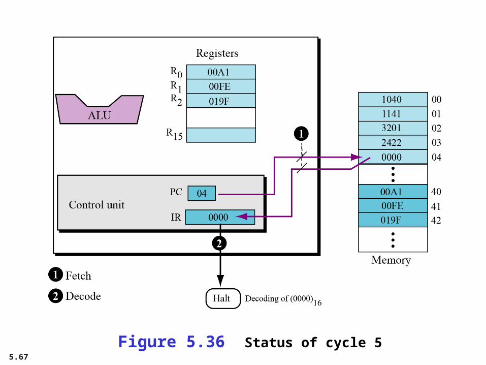
Processing the instructionsOur simple computer, like most computers, uses machine cycles. A cycle is made of three phases: fetch, decode and execute. During the fetch phase, the instruction whose address is determined by the PC is obtained from the memory and loaded into the IR. The PC is then incremented to point to the next instruction. During the decode phase, the instruction in IR is decoded and the required operands are fetched from the register or from memory. During the execute phase, the instruction is executed and the results are placed in the appropriate memory location or the register. Once the third phase is completed, the control unit starts the cycle again, but now the PC is pointing to the next instruction. The process continues until the CPU reaches a HALT instruction.

5.59

5.60
An exampleLet us show how our simple computer can add two integers A and B and create the result as C. We assume that integers are in two’s complement format. Mathematically, we show this operation as:
We assume that the first two integers are stored in memory locations (40)16 and (41)16 and the result should be stored inmemory location (42)16. To do the simple addition needs five instructions, as shown next:

5.61
In the language of our simple computer, these five instructions are encoded as:

5.62
Storing program and data
We can store the five-line program in memory starting from location (00)16 to (04)16. We already know that the data needs to be stored in memory locations (40)16, (41)16, and (42)16.
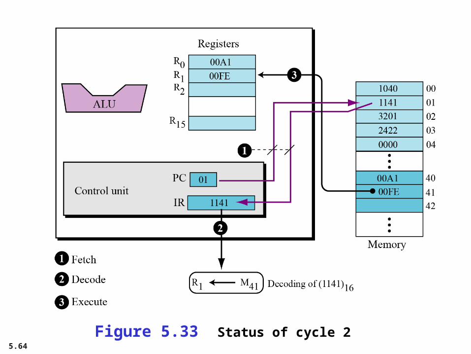
CyclesOur computer uses one cycle per instruction. If we have a small program with five instructions, we need five cycles. We also know that each cycle is normally made up of three steps: fetch, decode, execute. Assume for the moment that we need to add 161 + 254 = 415. The numbers are shown in memory in hexadecimal is, (00A1)16, (00FE)16, and (019F)16.

5.63
Figure 5.32 Status of cycle 1
5.64
Figure 5.33 Status of cycle 2

5.65
Figure 5.34 Status of cycle 3

5.66
Figure 5.35 Status of cycle 4
5.67
Figure 5.36 Status of cycle 5

5.68
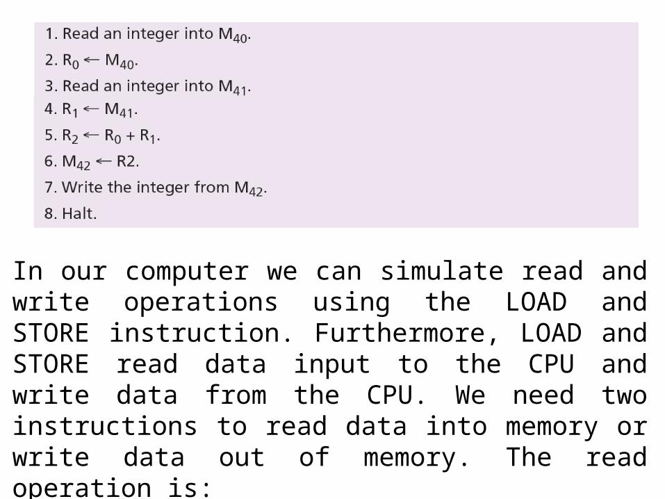
Another exampleIn the previous example we assumed that the two integers to be added were already in memory. We also assume that the result of addition will be held in memory. You may ask how we can store the two integers we want to add in memory, or how we use the result when it is stored in the memory. In a real situation, we enter the first two integers into memory using an input device such as keyboard, and we display the third integer through an output device such as a monitor. Getting data via an input device is normally called a read operation, while sending data to an output device is normally called a write operation. To make our previous program more practical, we need modify it as follows:
5.69
In our computer we can simulate read and write operations using the LOAD and STORE instruction. Furthermore, LOAD and STORE read data input to the CPU and write data from the CPU. We need two instructions to read data into memory or write data out of memory. The read operation is:

5.70
The write operation is:
The input operation must always read data from an input device into memory: the output operation must always write data from memory to an output device.
i

5.71
The program is coded as:
Operations 1 to 4 are for input and operations 9 and 10 are for output. When we run this program, it waits for the user to input two integers on the keyboard and press the enter key. The program then calculates the sum and displays the result on the monitor.