5054_s12_qp_41
Transcript of 5054_s12_qp_41

8/11/2019 5054_s12_qp_41
http://slidepdf.com/reader/full/5054s12qp41 1/12
This document consists of 11 printed pages and 1 blank page.
DC (NF/SW) 41130/4
© UCLES 2012 [Turn over
UNIVERSITY OF CAMBRIDGE INTERNATIONAL EXAMINATIONSGeneral Certificate of Education Ordinary Level
*
4
6
7
7
0
4
0
6
7
8
*
PHYSICS 5054/41
Paper 4 Alternative to Practical May/June 2012
1 hour
Candidates answer on the Question Paper.No Additional Materials are required.
READ THESE INSTRUCTIONS FIRST
Write your Centre number, candidate number and name on all the work you hand in.Write in dark blue or black pen.You may use a soft pencil for any diagrams, graphs or rough working.Do not use staples, paper clips, highlighters, glue or correction fluid.DO NOT WRITE IN ANY BARCODES.
Answer all questions.
You may lose marks if you do not show your working or if you do not use appropriate units.
At the end of the examination, fasten all your work securely together.The number of marks is given in brackets [ ] at the end of each question or part question.

8/11/2019 5054_s12_qp_41
http://slidepdf.com/reader/full/5054s12qp41 2/12
2
5054/41/M/J/12 © UCLES 2012
BLANK PAGE
8/11/2019 5054_s12_qp_41
http://slidepdf.com/reader/full/5054s12qp41 3/12
3
5054/41/M/J/12 © UCLES 2012 [Turn over
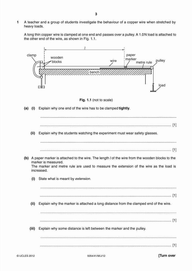
1 A teacher and a group of students investigate the behaviour of a copper wire when stretched byheavy loads.
A long thin copper wire is clamped at one end and passes over a pulley. A 1.0 N load is attached tothe other end of the wire, as shown in Fig. 1.1.
bench
l
clampwooden
blocks
paper
markermetre rule
pulley
load
wire
Fig. 1.1 (not to scale)
(a) (i) Explain why one end of the wire has to be clamped tightly.
...........................................................................................................................................
...................................................................................................................................... [1]
(ii) Explain why the students watching the experiment must wear safety glasses.
...........................................................................................................................................
...................................................................................................................................... [1]
(b) A paper marker is attached to the wire. The length l of the wire from the wooden blocks to themarker is measured.
The marker and metre rule are used to measure the extension of the wire as the load isincreased.
(i) State what is meant by extension .
...........................................................................................................................................
...................................................................................................................................... [1]
(ii) Explain why the marker is attached a long distance from the clamped end of the wire.
...........................................................................................................................................
...................................................................................................................................... [1]
(iii) Explain why some distance is left between the marker and the pulley.
...........................................................................................................................................
...................................................................................................................................... [1]
8/11/2019 5054_s12_qp_41
http://slidepdf.com/reader/full/5054s12qp41 4/12
4
5054/41/M/J/12 © UCLES 2012
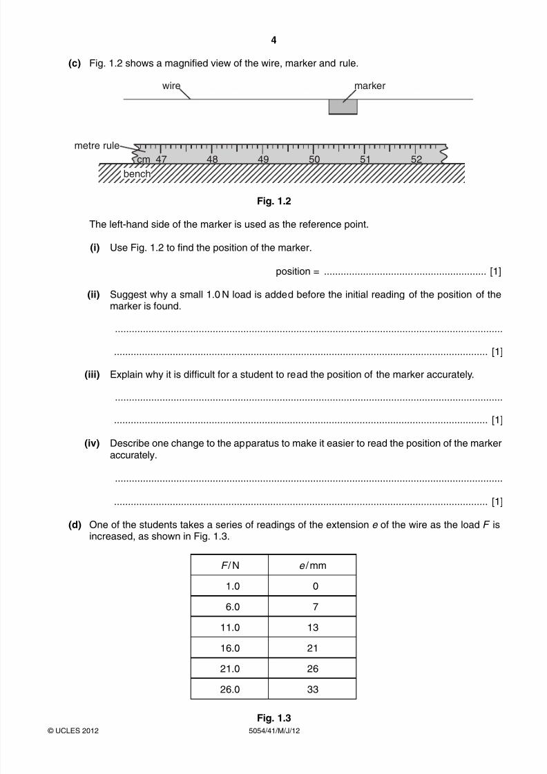
(c) Fig. 1.2 shows a magnified view of the wire, marker and rule.
47cm 48 49 50 51 52
bench
metre rule
wire marker
Fig. 1.2
The left-hand side of the marker is used as the reference point.
(i) Use Fig. 1.2 to find the position of the marker.
position = .......................................................... [1]
(ii) Suggest why a small 1.0 N load is added before the initial reading of the position of themarker is found.
...........................................................................................................................................
...................................................................................................................................... [1]
(iii) Explain why it is difficult for a student to read the position of the marker accurately.
...........................................................................................................................................
...................................................................................................................................... [1]
(iv) Describe one change to the apparatus to make it easier to read the position of the markeraccurately.
...........................................................................................................................................
...................................................................................................................................... [1]
(d) One of the students takes a series of readings of the extension e of the wire as the load F is
increased, as shown in Fig. 1.3.
F / N e / mm
1.0 0
6.0 7
11.0 13
16.0 21
21.0 26
26.0 33
Fig. 1.3

8/11/2019 5054_s12_qp_41
http://slidepdf.com/reader/full/5054s12qp41 5/12
5
5054/41/M/J/12 © UCLES 2012 [Turn over
(i) On Fig. 1.4, plot the graph of e / mm on the y -axis against F / N on the x -axis. Start your axes from the origin. Draw the line of best fit.
00
[4]
Fig. 1.4
(ii) Describe the relationship between F and e that is shown by your graph.
...........................................................................................................................................
...................................................................................................................................... [1]
(e) The teacher continues to increase the load. Describe what happens as the load becomesvery large.
...................................................................................................................................................
.............................................................................................................................................. [1]
8/11/2019 5054_s12_qp_41
http://slidepdf.com/reader/full/5054s12qp41 6/12

8/11/2019 5054_s12_qp_41
http://slidepdf.com/reader/full/5054s12qp41 7/12
7
5054/41/M/J/12 © UCLES 2012 [Turn over
(ii) Using the relationship
g =2.5 × 10³
3(l 2 – l 1)
calculate a value for g . Give your answer to two significant figures.
g = ................................................ m / s2 [2]
(b) The accepted value for g is 9.81 m / s2. State whether the value calculated for g in (a)(ii) is too large or too small. Suggest a reason
for this difference.
...................................................................................................................................................
...................................................................................................................................................
...................................................................................................................................................
...................................................................................................................................................
.............................................................................................................................................. [1]
8/11/2019 5054_s12_qp_41
http://slidepdf.com/reader/full/5054s12qp41 8/12
8
5054/41/M/J/12 © UCLES 2012
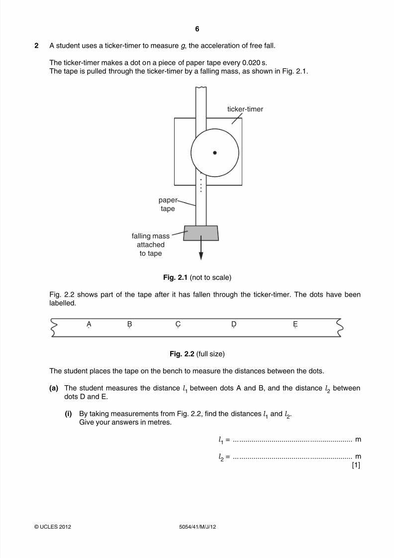
3 A student compares the conduction of heat through different metals. Fig. 3.1 shows the apparatus used.
metal rod
pea
hot water
metal
box
wax
Fig. 3.1
Four rods of different metals each have one end fixed through a cork into a metal box. The metal
box contains hot water. Each rod has a pea attached to it by wax.
(a) Heat from the hot water is conducted to the end of each rod. Describe what happens to the wax and to the pea on one of the rods.
...................................................................................................................................................
...................................................................................................................................................
.............................................................................................................................................. [1]
(b) State two factors that should be the same for all the rods in this experiment.
1. ...............................................................................................................................................
2. ............................................................................................................................................... [2]
(c) State how the experiment shows which of the metals is the best conductor of heat.
...................................................................................................................................................
.............................................................................................................................................. [1]
8/11/2019 5054_s12_qp_41
http://slidepdf.com/reader/full/5054s12qp41 9/12
9
5054/41/M/J/12 © UCLES 2012 [Turn over
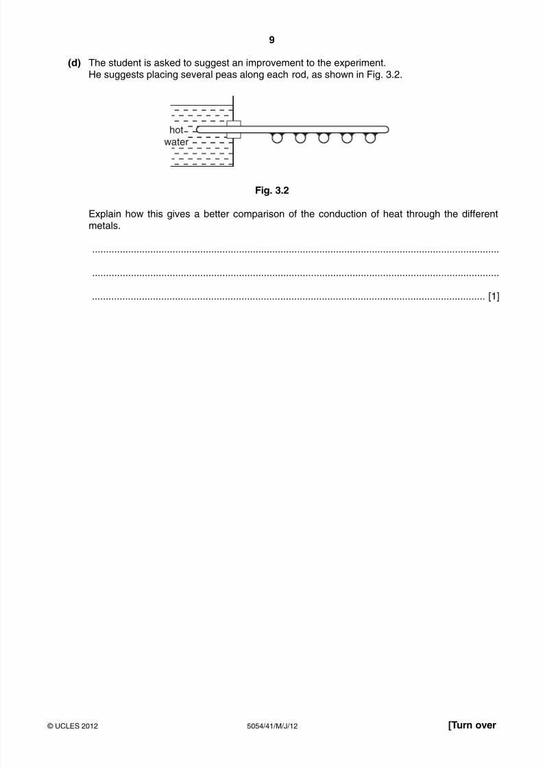
(d) The student is asked to suggest an improvement to the experiment. He suggests placing several peas along each rod, as shown in Fig. 3.2.
hotwater
Fig. 3.2
Explain how this gives a better comparison of the conduction of heat through the differentmetals.
...................................................................................................................................................
...................................................................................................................................................
.............................................................................................................................................. [1]
8/11/2019 5054_s12_qp_41
http://slidepdf.com/reader/full/5054s12qp41 10/12
10
5054/41/M/J/12 © UCLES 2012
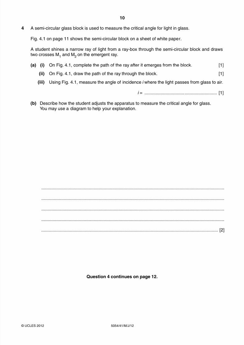
4 A semi-circular glass block is used to measure the critical angle for light in glass.
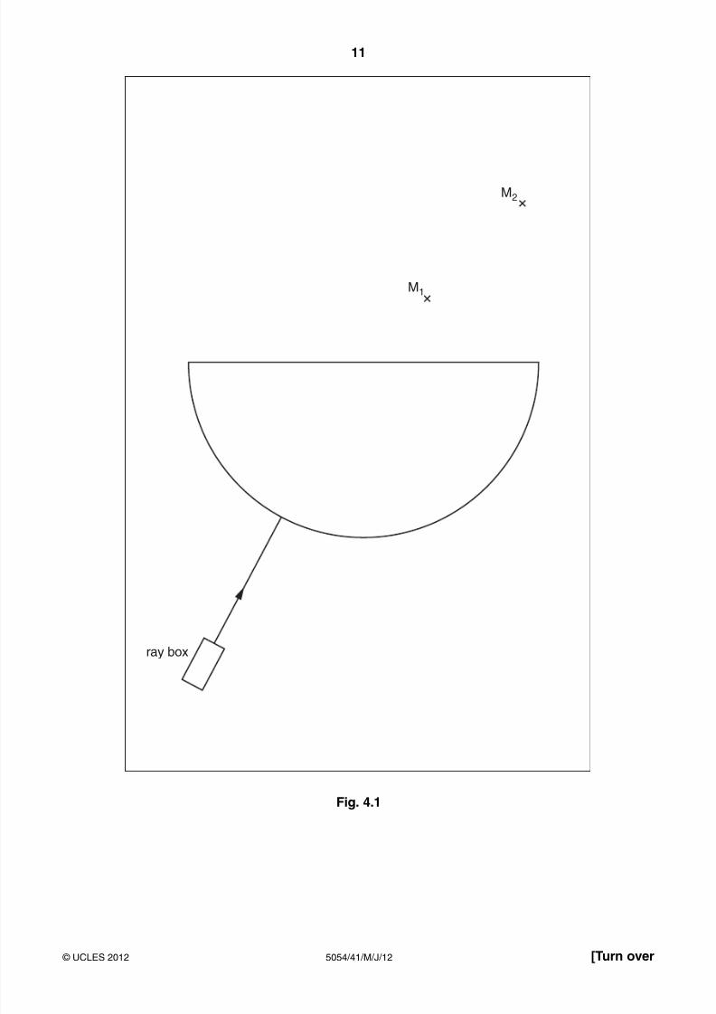
Fig. 4.1 on page 11 shows the semi-circular block on a sheet of white paper.
A student shines a narrow ray of light from a ray-box through the semi-circular block and drawstwo crosses M1 and M2 on the emergent ray.
(a) (i) On Fig. 4.1, complete the path of the ray after it emerges from the block. [1]
(ii) On Fig. 4.1, draw the path of the ray through the block. [1]
(iii) Using Fig. 4.1, measure the angle of incidence i where the light passes from glass to air.
i = .......................................................... [1]
(b) Describe how the student adjusts the apparatus to measure the critical angle for glass. You may use a diagram to help your explanation.
...................................................................................................................................................
...................................................................................................................................................
...................................................................................................................................................
...................................................................................................................................................
.............................................................................................................................................. [2]
Question 4 continues on page 12.
8/11/2019 5054_s12_qp_41
http://slidepdf.com/reader/full/5054s12qp41 11/12
11
5054/41/M/J/12 © UCLES 2012 [Turn over
M1
ray box
M2
Fig. 4.1
8/11/2019 5054_s12_qp_41
http://slidepdf.com/reader/full/5054s12qp41 12/12
12
5054/41/M/J/12 © UCLES 2012
Permission to reproduce items where third-party owned material protected by copyright is included has been sought and cleared where possible. Everyreasonable effort has been made by the publisher (UCLES) to trace copyright holders, but if any items requiring clearance have unwittingly been included, the
publisher will be pleased to make amends at the earliest possible opportunity.
University of Cambridge International Examinations is part of the Cambridge Assessment Group. Cambridge Assessment is the brand name of University of
Cambridge Local Examinations Syndicate (UCLES), which is itself a department of the University of Cambridge.
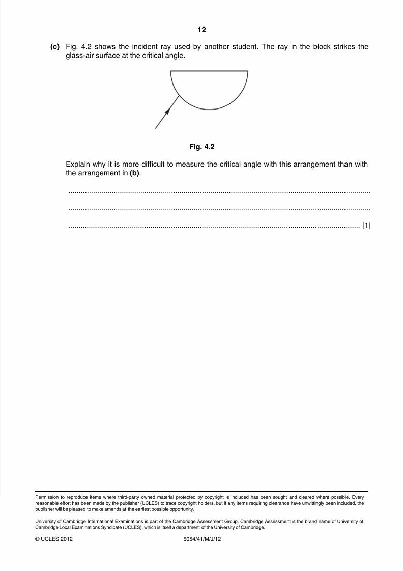
(c) Fig. 4.2 shows the incident ray used by another student. The ray in the block strikes theglass-air surface at the critical angle.
Fig. 4.2
Explain why it is more difficult to measure the critical angle with this arrangement than withthe arrangement in (b).
...................................................................................................................................................
...................................................................................................................................................
.............................................................................................................................................. [1]