505-6850-B - SIEMENS - Texas Instruments - … · MANUAL PUBLICATION HISTORY SIMATIC 545/555/575...
322
SIMATIC 545/555/575 System Manual Order Number: PPX:505-8201-3 Manual Assembly Number: 2804693-0003 Third Edition
Transcript of 505-6850-B - SIEMENS - Texas Instruments - … · MANUAL PUBLICATION HISTORY SIMATIC 545/555/575...

!" #$""%& '&&(

! DANGERDANGER indicates an imminently hazardous situation that, if not avoided, willresult in death or serious injury.
DANGER is limited to the most extreme situations.
! WARNINGWARNING indicates a potentially hazardous situation that, if not avoided, couldresult in death or serious injury, and/or property damage.
! CAUTIONCAUTION indicates a potentially hazardous situation that, if not avoided, couldresult in minor or moderate injury, and/or damage to property.
CAUTIONCAUTION without the safety alert symbol indicates a potentially hazardous situ-ation that, if not avoided, could result in property damage.
Copyright 2000 by Siemens Energy & Automation, Inc.All Rights Reserved — Printed in USA
Reproduction, transmission, or use of this document or contents is not permitted without express consent ofSiemens Energy & Automation, Inc. All rights, including rights created by patent grant or registration of a utility model or design, arereserved.
Since Siemens Energy & Automation, Inc., does not possess full access to data concerning all of the uses and applications ofcustomer’s products, we do not assume responsibility either for customer product design or for any infringements of patents or rightsof others which may result from our assistance.

MANUAL PUBLICATION HISTORY
SIMATIC 545/555/575 System ManualOrder Manual Number: PPX:505–8201–3Refer to this history in all correspondence and/or discussion about this manual.
Event Date Description
Original Issue 03/96 Original Issue (2804693–0001)Second Edition 08/98 Second Edition (2804693–0002)Third Edition 06/00 Third Edition (2804693–0003)

LIST OF EFFECTIVE PAGES
Pages Description Pages Description
Cover/Copyright Third EditionHistory/Effective Pages Third Editioniii — xxi Third Edition1-1 — 1-13 Third Edition2-1 — 2-20 Third Edition
3-1 — 3-28 Third Edition4-1 — 4-58 Third Edition5-1 — 5-24 Third Edition6-1 — 6-35 Third Edition7-1 — 7-12 Third Edition8-1 — 8-8 Third Edition
9-1 — 9-25 Third EditionA-1 — A-5 Third EditionB-1 — B-9 Third EditionC-1 — C-23 Third EditionD-1 — D-7 Third EditionE-1 — E-16 Third EditionF-1 — F-6 Third Edition
Index-1 — Index-10 Third EditionRegistration Third Edition

Contents iii
Contents
Preface
Chapter 1 System Overview
1.1 Overview 1-2. . . . . . . . . . . . . . . . . . . . . . . . . . . . . . . . . . . . . . . . . . . . . . . . . . . . . . . . . . . . . . . . . . . . . . . Introduction 1-2. . . . . . . . . . . . . . . . . . . . . . . . . . . . . . . . . . . . . . . . . . . . . . . . . . . . . . . . . . . . . . . . . . . . Compatibility with Previous CPUs 1-2. . . . . . . . . . . . . . . . . . . . . . . . . . . . . . . . . . . . . . . . . . . . . . . . Features on New CPU Models 1-3. . . . . . . . . . . . . . . . . . . . . . . . . . . . . . . . . . . . . . . . . . . . . . . . . . . PROFIBUS-DP 1-4. . . . . . . . . . . . . . . . . . . . . . . . . . . . . . . . . . . . . . . . . . . . . . . . . . . . . . . . . . . . . . . . . . . PROFIBUS User Organizations 1-4. . . . . . . . . . . . . . . . . . . . . . . . . . . . . . . . . . . . . . . . . . . . . . . . . . . . Using Other Networks 1-4. . . . . . . . . . . . . . . . . . . . . . . . . . . . . . . . . . . . . . . . . . . . . . . . . . . . . . . . . . .
1.2 System Features 1-6. . . . . . . . . . . . . . . . . . . . . . . . . . . . . . . . . . . . . . . . . . . . . . . . . . . . . . . . . . . . . . . . Product Specifications Overview 1-6. . . . . . . . . . . . . . . . . . . . . . . . . . . . . . . . . . . . . . . . . . . . . . . . Shared Features 1-8. . . . . . . . . . . . . . . . . . . . . . . . . . . . . . . . . . . . . . . . . . . . . . . . . . . . . . . . . . . . . . . . 545/555-Only Features 1-9. . . . . . . . . . . . . . . . . . . . . . . . . . . . . . . . . . . . . . . . . . . . . . . . . . . . . . . . . . 575-Only Features 1-10. . . . . . . . . . . . . . . . . . . . . . . . . . . . . . . . . . . . . . . . . . . . . . . . . . . . . . . . . . . . . . .
1.3 Programming Tools 1-11. . . . . . . . . . . . . . . . . . . . . . . . . . . . . . . . . . . . . . . . . . . . . . . . . . . . . . . . . . . . . . SoftShop 1-11. . . . . . . . . . . . . . . . . . . . . . . . . . . . . . . . . . . . . . . . . . . . . . . . . . . . . . . . . . . . . . . . . . . . . . . TISOFT 1-11. . . . . . . . . . . . . . . . . . . . . . . . . . . . . . . . . . . . . . . . . . . . . . . . . . . . . . . . . . . . . . . . . . . . . . . . . . COM PROFIBUS 1-11. . . . . . . . . . . . . . . . . . . . . . . . . . . . . . . . . . . . . . . . . . . . . . . . . . . . . . . . . . . . . . . . . Communicating with the CPU 1-11. . . . . . . . . . . . . . . . . . . . . . . . . . . . . . . . . . . . . . . . . . . . . . . . . . .
1.4 Hardware Overview 1-12. . . . . . . . . . . . . . . . . . . . . . . . . . . . . . . . . . . . . . . . . . . . . . . . . . . . . . . . . . . . . Series 505 Bases 1-12. . . . . . . . . . . . . . . . . . . . . . . . . . . . . . . . . . . . . . . . . . . . . . . . . . . . . . . . . . . . . . . . . VME Base 1-12. . . . . . . . . . . . . . . . . . . . . . . . . . . . . . . . . . . . . . . . . . . . . . . . . . . . . . . . . . . . . . . . . . . . . . Expansion I/O 1-13. . . . . . . . . . . . . . . . . . . . . . . . . . . . . . . . . . . . . . . . . . . . . . . . . . . . . . . . . . . . . . . . . . I/O Channel Support 1-13. . . . . . . . . . . . . . . . . . . . . . . . . . . . . . . . . . . . . . . . . . . . . . . . . . . . . . . . . . . .
Chapter 2 Pre-installation Guidelines
2.1 Planning Your Installation 2-2. . . . . . . . . . . . . . . . . . . . . . . . . . . . . . . . . . . . . . . . . . . . . . . . . . . . . . . . Defining Control Requirements 2-2. . . . . . . . . . . . . . . . . . . . . . . . . . . . . . . . . . . . . . . . . . . . . . . . . . Calculating Power Needs 2-2. . . . . . . . . . . . . . . . . . . . . . . . . . . . . . . . . . . . . . . . . . . . . . . . . . . . . . .
2.2 Safety Considerations 2-3. . . . . . . . . . . . . . . . . . . . . . . . . . . . . . . . . . . . . . . . . . . . . . . . . . . . . . . . . . . Operator Safety Switches 2-4. . . . . . . . . . . . . . . . . . . . . . . . . . . . . . . . . . . . . . . . . . . . . . . . . . . . . . . Emergency Stop Switch 2-4. . . . . . . . . . . . . . . . . . . . . . . . . . . . . . . . . . . . . . . . . . . . . . . . . . . . . . . . . JOG or INCH Switch 2-5. . . . . . . . . . . . . . . . . . . . . . . . . . . . . . . . . . . . . . . . . . . . . . . . . . . . . . . . . . . . .
2.3 575 Fault Relay Operation 2-6. . . . . . . . . . . . . . . . . . . . . . . . . . . . . . . . . . . . . . . . . . . . . . . . . . . . . . . Overview 2-6. . . . . . . . . . . . . . . . . . . . . . . . . . . . . . . . . . . . . . . . . . . . . . . . . . . . . . . . . . . . . . . . . . . . . . . Fault Relay Operation Details 2-6. . . . . . . . . . . . . . . . . . . . . . . . . . . . . . . . . . . . . . . . . . . . . . . . . . . . Time Delay 2-8. . . . . . . . . . . . . . . . . . . . . . . . . . . . . . . . . . . . . . . . . . . . . . . . . . . . . . . . . . . . . . . . . . . . . Fault Relay Usage Examples 2-8. . . . . . . . . . . . . . . . . . . . . . . . . . . . . . . . . . . . . . . . . . . . . . . . . . . . .

iv Contents
2.4 Guidelines for Fuses/Circuit Breakers 2-11. . . . . . . . . . . . . . . . . . . . . . . . . . . . . . . . . . . . . . . . . . . . . Fusing the Controller and Remote I/O Base 2-11. . . . . . . . . . . . . . . . . . . . . . . . . . . . . . . . . . . . . . .
2.5 Electrical Noise 2-12. . . . . . . . . . . . . . . . . . . . . . . . . . . . . . . . . . . . . . . . . . . . . . . . . . . . . . . . . . . . . . . . .
Definition and Source 2-12. . . . . . . . . . . . . . . . . . . . . . . . . . . . . . . . . . . . . . . . . . . . . . . . . . . . . . . . . . .
2.6 Correcting Noise Problems 2-13. . . . . . . . . . . . . . . . . . . . . . . . . . . . . . . . . . . . . . . . . . . . . . . . . . . . . . Noise Snubbing 2-13. . . . . . . . . . . . . . . . . . . . . . . . . . . . . . . . . . . . . . . . . . . . . . . . . . . . . . . . . . . . . . . . . Noise Isolation 2-15. . . . . . . . . . . . . . . . . . . . . . . . . . . . . . . . . . . . . . . . . . . . . . . . . . . . . . . . . . . . . . . . . .
2.7 Wiring Guidelines 2-16. . . . . . . . . . . . . . . . . . . . . . . . . . . . . . . . . . . . . . . . . . . . . . . . . . . . . . . . . . . . . . .
2.8 Grounding the Power System 2-17. . . . . . . . . . . . . . . . . . . . . . . . . . . . . . . . . . . . . . . . . . . . . . . . . . . .
Earth Ground 2-17. . . . . . . . . . . . . . . . . . . . . . . . . . . . . . . . . . . . . . . . . . . . . . . . . . . . . . . . . . . . . . . . . . . Ground Connections 2-18. . . . . . . . . . . . . . . . . . . . . . . . . . . . . . . . . . . . . . . . . . . . . . . . . . . . . . . . . . . Grounding the 545/555 Controller Chassis 2-19. . . . . . . . . . . . . . . . . . . . . . . . . . . . . . . . . . . . . . . . Grounding the Cabinet or Rack 2-19. . . . . . . . . . . . . . . . . . . . . . . . . . . . . . . . . . . . . . . . . . . . . . . . . Cable Management for the 575 2-20. . . . . . . . . . . . . . . . . . . . . . . . . . . . . . . . . . . . . . . . . . . . . . . . . Grounding the 575 Controller Chassis 2-20. . . . . . . . . . . . . . . . . . . . . . . . . . . . . . . . . . . . . . . . . . . . Grounding the Cabinet or Rack 2-20. . . . . . . . . . . . . . . . . . . . . . . . . . . . . . . . . . . . . . . . . . . . . . . . .
Chapter 3 Installing 505 System Hardware
3.1 Overview of Installation Procedures 3-2. . . . . . . . . . . . . . . . . . . . . . . . . . . . . . . . . . . . . . . . . . . . . .
3.2 Enclosure and Temperature Considerations 3-3. . . . . . . . . . . . . . . . . . . . . . . . . . . . . . . . . . . . . .
Enclosure Selection 3-3. . . . . . . . . . . . . . . . . . . . . . . . . . . . . . . . . . . . . . . . . . . . . . . . . . . . . . . . . . . . . Temperature Considerations 3-3. . . . . . . . . . . . . . . . . . . . . . . . . . . . . . . . . . . . . . . . . . . . . . . . . . . . .
3.3 Series 505 Bases 3-4. . . . . . . . . . . . . . . . . . . . . . . . . . . . . . . . . . . . . . . . . . . . . . . . . . . . . . . . . . . . . . . .
Description 3-4. . . . . . . . . . . . . . . . . . . . . . . . . . . . . . . . . . . . . . . . . . . . . . . . . . . . . . . . . . . . . . . . . . . . . Grounding the Controller Chassis 3-4. . . . . . . . . . . . . . . . . . . . . . . . . . . . . . . . . . . . . . . . . . . . . . . .
3.4 Rack Mounting Series 505 Bases 3-5. . . . . . . . . . . . . . . . . . . . . . . . . . . . . . . . . . . . . . . . . . . . . . . . .
3.5 Panel Mounting Series 505 Bases 3-6. . . . . . . . . . . . . . . . . . . . . . . . . . . . . . . . . . . . . . . . . . . . . . . . .
3.6 Installing Series 505 Power Supply 3-8. . . . . . . . . . . . . . . . . . . . . . . . . . . . . . . . . . . . . . . . . . . . . . . .
Power Budget for Series 505 Base 3-8. . . . . . . . . . . . . . . . . . . . . . . . . . . . . . . . . . . . . . . . . . . . . . . . Power Supply Placement in Bases 3-8. . . . . . . . . . . . . . . . . . . . . . . . . . . . . . . . . . . . . . . . . . . . . . . . Installing and Removing the Power Supply 3-8. . . . . . . . . . . . . . . . . . . . . . . . . . . . . . . . . . . . . . . Wiring the Power Supply 3-10. . . . . . . . . . . . . . . . . . . . . . . . . . . . . . . . . . . . . . . . . . . . . . . . . . . . . . . . .
3.7 Installing the PROFIBUS-DP Annex Card (Optional) 3-12. . . . . . . . . . . . . . . . . . . . . . . . . . . . . . . .
3.8 Installing the 545/555 CPU 3-14. . . . . . . . . . . . . . . . . . . . . . . . . . . . . . . . . . . . . . . . . . . . . . . . . . . . . . .
CPU/RBC Location in a Base 3-14. . . . . . . . . . . . . . . . . . . . . . . . . . . . . . . . . . . . . . . . . . . . . . . . . . . . . Installing and Removing the CPU 3-14. . . . . . . . . . . . . . . . . . . . . . . . . . . . . . . . . . . . . . . . . . . . . . . .

Contents v
3.9 Replacing and Handling the Battery 3-16. . . . . . . . . . . . . . . . . . . . . . . . . . . . . . . . . . . . . . . . . . . . . Lithium Battery in the 545 and 555 –1105/–1106 CPUs 3-16. . . . . . . . . . . . . . . . . . . . . . . . . . . . . . Replacing the Battery in –1105/–1106 CPUs 3-17. . . . . . . . . . . . . . . . . . . . . . . . . . . . . . . . . . . . . . . Lithium Battery in the 545 and 555 –1103/–1104 CPUs 3-18. . . . . . . . . . . . . . . . . . . . . . . . . . . . . . Indicators 3-18. . . . . . . . . . . . . . . . . . . . . . . . . . . . . . . . . . . . . . . . . . . . . . . . . . . . . . . . . . . . . . . . . . . . . . Using and Handling Batteries 3-19. . . . . . . . . . . . . . . . . . . . . . . . . . . . . . . . . . . . . . . . . . . . . . . . . . . . Transporting Batteries 3-19. . . . . . . . . . . . . . . . . . . . . . . . . . . . . . . . . . . . . . . . . . . . . . . . . . . . . . . . . . . Storing Batteries 3-19. . . . . . . . . . . . . . . . . . . . . . . . . . . . . . . . . . . . . . . . . . . . . . . . . . . . . . . . . . . . . . . . Discarding Batteries 3-19. . . . . . . . . . . . . . . . . . . . . . . . . . . . . . . . . . . . . . . . . . . . . . . . . . . . . . . . . . . . . Replacing the Battery in –1103/–1104 CPUs 3-20. . . . . . . . . . . . . . . . . . . . . . . . . . . . . . . . . . . . . . .
3.10 Setting the CPU Dipswitches 3-22. . . . . . . . . . . . . . . . . . . . . . . . . . . . . . . . . . . . . . . . . . . . . . . . . . . . . Dipswitch Location and Settings 3-22. . . . . . . . . . . . . . . . . . . . . . . . . . . . . . . . . . . . . . . . . . . . . . . . . Enabling Battery Backup 3-22. . . . . . . . . . . . . . . . . . . . . . . . . . . . . . . . . . . . . . . . . . . . . . . . . . . . . . . . Enabling the Auto Recompile Function 3-22. . . . . . . . . . . . . . . . . . . . . . . . . . . . . . . . . . . . . . . . . . . Setting Baud Rates 3-23. . . . . . . . . . . . . . . . . . . . . . . . . . . . . . . . . . . . . . . . . . . . . . . . . . . . . . . . . . . . . . Communications Port 1 3-24. . . . . . . . . . . . . . . . . . . . . . . . . . . . . . . . . . . . . . . . . . . . . . . . . . . . . . . . . Communications Port 2 3-24. . . . . . . . . . . . . . . . . . . . . . . . . . . . . . . . . . . . . . . . . . . . . . . . . . . . . . . . . I/O Ports 3-25. . . . . . . . . . . . . . . . . . . . . . . . . . . . . . . . . . . . . . . . . . . . . . . . . . . . . . . . . . . . . . . . . . . . . . . .
3.11 Installing Series 505 I/O Modules 3-26. . . . . . . . . . . . . . . . . . . . . . . . . . . . . . . . . . . . . . . . . . . . . . . . . Mixing I/O Modules 3-26. . . . . . . . . . . . . . . . . . . . . . . . . . . . . . . . . . . . . . . . . . . . . . . . . . . . . . . . . . . . . Installing and Removing I/O Modules 3-26. . . . . . . . . . . . . . . . . . . . . . . . . . . . . . . . . . . . . . . . . . . .
Chapter 4 Installing 575 System Hardware
4.1 Overview of Installation Procedures 4-2. . . . . . . . . . . . . . . . . . . . . . . . . . . . . . . . . . . . . . . . . . . . . .
4.2 Features of the PPX:575–2130 VMEbus Base 4-3. . . . . . . . . . . . . . . . . . . . . . . . . . . . . . . . . . . . . . . Overview 4-3. . . . . . . . . . . . . . . . . . . . . . . . . . . . . . . . . . . . . . . . . . . . . . . . . . . . . . . . . . . . . . . . . . . . . . .
4.3 Features Required of a Third-Party VMEbus Base 4-4. . . . . . . . . . . . . . . . . . . . . . . . . . . . . . . . . . VMEbus Base Requirements 4-4. . . . . . . . . . . . . . . . . . . . . . . . . . . . . . . . . . . . . . . . . . . . . . . . . . . . . Determining the Condition of the 575 CPU Battery 4-4. . . . . . . . . . . . . . . . . . . . . . . . . . . . . . . .
4.4 Enclosure and Temperature Considerations 4-5. . . . . . . . . . . . . . . . . . . . . . . . . . . . . . . . . . . . . . Enclosure Selection 4-5. . . . . . . . . . . . . . . . . . . . . . . . . . . . . . . . . . . . . . . . . . . . . . . . . . . . . . . . . . . . . Temperature Considerations 4-5. . . . . . . . . . . . . . . . . . . . . . . . . . . . . . . . . . . . . . . . . . . . . . . . . . . . .
4.5 Installing the Fan Assembly 4-6. . . . . . . . . . . . . . . . . . . . . . . . . . . . . . . . . . . . . . . . . . . . . . . . . . . . . . Operating With Fan Assembly 4-6. . . . . . . . . . . . . . . . . . . . . . . . . . . . . . . . . . . . . . . . . . . . . . . . . . . Operating Without Fan Assembly 4-6. . . . . . . . . . . . . . . . . . . . . . . . . . . . . . . . . . . . . . . . . . . . . . . . Installation Sequence 4-6. . . . . . . . . . . . . . . . . . . . . . . . . . . . . . . . . . . . . . . . . . . . . . . . . . . . . . . . . . . Selecting Voltage for Fan Operation 4-7. . . . . . . . . . . . . . . . . . . . . . . . . . . . . . . . . . . . . . . . . . . . . Wiring the AC Power Terminals 4-7. . . . . . . . . . . . . . . . . . . . . . . . . . . . . . . . . . . . . . . . . . . . . . . . . . . Mounting the Fan Assembly 4-8. . . . . . . . . . . . . . . . . . . . . . . . . . . . . . . . . . . . . . . . . . . . . . . . . . . . . Replacing Fuse on the Fan Assembly 4-9. . . . . . . . . . . . . . . . . . . . . . . . . . . . . . . . . . . . . . . . . . . . .

vi Contents
4.6 Installing the PPX:575–2130 VMEbus Base 4-10. . . . . . . . . . . . . . . . . . . . . . . . . . . . . . . . . . . . . . . . . Mechanical Outline 4-10. . . . . . . . . . . . . . . . . . . . . . . . . . . . . . . . . . . . . . . . . . . . . . . . . . . . . . . . . . . . . Mounting Measurements 4-10. . . . . . . . . . . . . . . . . . . . . . . . . . . . . . . . . . . . . . . . . . . . . . . . . . . . . . . . Mounting a Base in a 19-inch Rack 4-11. . . . . . . . . . . . . . . . . . . . . . . . . . . . . . . . . . . . . . . . . . . . . . NEMA Cabinet Mounting Measurements 4-12. . . . . . . . . . . . . . . . . . . . . . . . . . . . . . . . . . . . . . . . . Panel Mounting the Base 4-12. . . . . . . . . . . . . . . . . . . . . . . . . . . . . . . . . . . . . . . . . . . . . . . . . . . . . . . . Grounding the Controller Chassis 4-13. . . . . . . . . . . . . . . . . . . . . . . . . . . . . . . . . . . . . . . . . . . . . . . .
4.7 Installing the 575 Power Supply 4-14. . . . . . . . . . . . . . . . . . . . . . . . . . . . . . . . . . . . . . . . . . . . . . . . . . Overview 4-14. . . . . . . . . . . . . . . . . . . . . . . . . . . . . . . . . . . . . . . . . . . . . . . . . . . . . . . . . . . . . . . . . . . . . . . Selecting Input Voltage (PPX:575–6663 Only) 4-16. . . . . . . . . . . . . . . . . . . . . . . . . . . . . . . . . . . . . Installing the 575 Power Supply 4-17. . . . . . . . . . . . . . . . . . . . . . . . . . . . . . . . . . . . . . . . . . . . . . . . . . Wiring Guidelines 4-17. . . . . . . . . . . . . . . . . . . . . . . . . . . . . . . . . . . . . . . . . . . . . . . . . . . . . . . . . . . . . . . Wiring Procedure 4-18. . . . . . . . . . . . . . . . . . . . . . . . . . . . . . . . . . . . . . . . . . . . . . . . . . . . . . . . . . . . . . .
4.8 Installing the Battery 4-20. . . . . . . . . . . . . . . . . . . . . . . . . . . . . . . . . . . . . . . . . . . . . . . . . . . . . . . . . . . . Battery Backup for the 575 4-20. . . . . . . . . . . . . . . . . . . . . . . . . . . . . . . . . . . . . . . . . . . . . . . . . . . . . . Mounting the Battery 4-20. . . . . . . . . . . . . . . . . . . . . . . . . . . . . . . . . . . . . . . . . . . . . . . . . . . . . . . . . . . Disabling the Battery 4-22. . . . . . . . . . . . . . . . . . . . . . . . . . . . . . . . . . . . . . . . . . . . . . . . . . . . . . . . . . . . Battery Fuse 4-22. . . . . . . . . . . . . . . . . . . . . . . . . . . . . . . . . . . . . . . . . . . . . . . . . . . . . . . . . . . . . . . . . . . .
4.9 Installing the Floating-Point Coprocessor (Optional) 4-23. . . . . . . . . . . . . . . . . . . . . . . . . . . . . . .
4.10 Configuring the CPU 4-24. . . . . . . . . . . . . . . . . . . . . . . . . . . . . . . . . . . . . . . . . . . . . . . . . . . . . . . . . . . . Configuring the 575–2105/–2106 CPU 4-24. . . . . . . . . . . . . . . . . . . . . . . . . . . . . . . . . . . . . . . . . . . . Configuring the 575–2104 CPU 4-24. . . . . . . . . . . . . . . . . . . . . . . . . . . . . . . . . . . . . . . . . . . . . . . . . . . Using the AUTO-CONFIGURED Mode 4-26. . . . . . . . . . . . . . . . . . . . . . . . . . . . . . . . . . . . . . . . . . . . . Using the USER-CONFIGURED Mode 4-26. . . . . . . . . . . . . . . . . . . . . . . . . . . . . . . . . . . . . . . . . . . . . . Configuring the 575 Primary and Secondaries 4-26. . . . . . . . . . . . . . . . . . . . . . . . . . . . . . . . . . . . Enabling the Auto Recompile Function 4-26. . . . . . . . . . . . . . . . . . . . . . . . . . . . . . . . . . . . . . . . . . . Setting the Base Address 4-27. . . . . . . . . . . . . . . . . . . . . . . . . . . . . . . . . . . . . . . . . . . . . . . . . . . . . . . . Issuing SYSRESET 4-27. . . . . . . . . . . . . . . . . . . . . . . . . . . . . . . . . . . . . . . . . . . . . . . . . . . . . . . . . . . . . . . . .
4.11 Installing a Remote I/O Annex Card (Optional) 4-28. . . . . . . . . . . . . . . . . . . . . . . . . . . . . . . . . . . Configuring Annex Card Dipswitch 4-28. . . . . . . . . . . . . . . . . . . . . . . . . . . . . . . . . . . . . . . . . . . . . . Annex Card Power Consumption 4-28. . . . . . . . . . . . . . . . . . . . . . . . . . . . . . . . . . . . . . . . . . . . . . . . Installing the Series 505 Remote I/O Annex Card 4-29. . . . . . . . . . . . . . . . . . . . . . . . . . . . . . . . . . Installing the PROFIBUS-DP Annex Card 4-30. . . . . . . . . . . . . . . . . . . . . . . . . . . . . . . . . . . . . . . . . . .
4.12 Installing VMEbus Boards 4-32. . . . . . . . . . . . . . . . . . . . . . . . . . . . . . . . . . . . . . . . . . . . . . . . . . . . . . . . Introduction 4-32. . . . . . . . . . . . . . . . . . . . . . . . . . . . . . . . . . . . . . . . . . . . . . . . . . . . . . . . . . . . . . . . . . . . General Guidelines 4-34. . . . . . . . . . . . . . . . . . . . . . . . . . . . . . . . . . . . . . . . . . . . . . . . . . . . . . . . . . . . . Guidelines for Installing a 575 System Controller or a Primary 575 4-35. . . . . . . . . . . . . . . . . . . Guidelines for Installing or Adding a 575 Secondary to the System 4-36. . . . . . . . . . . . . . . . . Guidelines for Replacing a 575 System Controller 4-37. . . . . . . . . . . . . . . . . . . . . . . . . . . . . . . . . Guidelines for Replacing a 575 Primary Not in Slot 1 4-38. . . . . . . . . . . . . . . . . . . . . . . . . . . . . . . Guidelines for Replacing a 575 Secondary 4-39. . . . . . . . . . . . . . . . . . . . . . . . . . . . . . . . . . . . . . . Guidelines for Installing SIMATIC VMEbus I/O and Third-Party Boards 4-40. . . . . . . . . . . . . . . . Setting the Daisy-Chain Switches 4-41. . . . . . . . . . . . . . . . . . . . . . . . . . . . . . . . . . . . . . . . . . . . . . . . Slot Numbering 4-41. . . . . . . . . . . . . . . . . . . . . . . . . . . . . . . . . . . . . . . . . . . . . . . . . . . . . . . . . . . . . . . . . Installing and Removing I/O Modules 4-42. . . . . . . . . . . . . . . . . . . . . . . . . . . . . . . . . . . . . . . . . . . .
Contents vii
4.13 Wiring the Fault Relay 4-44. . . . . . . . . . . . . . . . . . . . . . . . . . . . . . . . . . . . . . . . . . . . . . . . . . . . . . . . . . .
4.14 Establishing CPU Communication 4-45. . . . . . . . . . . . . . . . . . . . . . . . . . . . . . . . . . . . . . . . . . . . . . . . Default Port Configurations 4-45. . . . . . . . . . . . . . . . . . . . . . . . . . . . . . . . . . . . . . . . . . . . . . . . . . . . . . Pinout for Serial Port 1 4-46. . . . . . . . . . . . . . . . . . . . . . . . . . . . . . . . . . . . . . . . . . . . . . . . . . . . . . . . . . . Pinouts for Serial Ports 2, 3, and 4 4-46. . . . . . . . . . . . . . . . . . . . . . . . . . . . . . . . . . . . . . . . . . . . . . . . . Serial Port 1 4-47. . . . . . . . . . . . . . . . . . . . . . . . . . . . . . . . . . . . . . . . . . . . . . . . . . . . . . . . . . . . . . . . . . . . . Serial Port 2/ Printer Port 4-48. . . . . . . . . . . . . . . . . . . . . . . . . . . . . . . . . . . . . . . . . . . . . . . . . . . . . . . . . Serial Port 3 4-49. . . . . . . . . . . . . . . . . . . . . . . . . . . . . . . . . . . . . . . . . . . . . . . . . . . . . . . . . . . . . . . . . . . . . Serial Port 4 4-49. . . . . . . . . . . . . . . . . . . . . . . . . . . . . . . . . . . . . . . . . . . . . . . . . . . . . . . . . . . . . . . . . . . . .
4.15 Using Boards in the VMEbus Base 4-50. . . . . . . . . . . . . . . . . . . . . . . . . . . . . . . . . . . . . . . . . . . . . . . . Communicating with the CPU 4-50. . . . . . . . . . . . . . . . . . . . . . . . . . . . . . . . . . . . . . . . . . . . . . . . . . . Battery Status 4-51. . . . . . . . . . . . . . . . . . . . . . . . . . . . . . . . . . . . . . . . . . . . . . . . . . . . . . . . . . . . . . . . . . . Using VMEbus Address Space 4-51. . . . . . . . . . . . . . . . . . . . . . . . . . . . . . . . . . . . . . . . . . . . . . . . . . . Daisy-Chain Signals 4-53. . . . . . . . . . . . . . . . . . . . . . . . . . . . . . . . . . . . . . . . . . . . . . . . . . . . . . . . . . . . . Assigning Addresses to Third-Party Slaves 4-53. . . . . . . . . . . . . . . . . . . . . . . . . . . . . . . . . . . . . . . . . VMEbus Access Limitations 4-55. . . . . . . . . . . . . . . . . . . . . . . . . . . . . . . . . . . . . . . . . . . . . . . . . . . . . .
4.16 Installing Additional Backplane Connectors 4-56. . . . . . . . . . . . . . . . . . . . . . . . . . . . . . . . . . . . . . J2 Backplanes 4-56. . . . . . . . . . . . . . . . . . . . . . . . . . . . . . . . . . . . . . . . . . . . . . . . . . . . . . . . . . . . . . . . . . Optional J2 Mini Backplane Kit 4-56. . . . . . . . . . . . . . . . . . . . . . . . . . . . . . . . . . . . . . . . . . . . . . . . . . Installing Optional J2 Backplane 4-57. . . . . . . . . . . . . . . . . . . . . . . . . . . . . . . . . . . . . . . . . . . . . . . . . Installing Optional J2 DIN Connector 4-58. . . . . . . . . . . . . . . . . . . . . . . . . . . . . . . . . . . . . . . . . . . . .
Chapter 5 Installing Remote Base Controllers—RBCs
5.1 Overview 5-2. . . . . . . . . . . . . . . . . . . . . . . . . . . . . . . . . . . . . . . . . . . . . . . . . . . . . . . . . . . . . . . . . . . . . . .
5.2 Installation 5-3. . . . . . . . . . . . . . . . . . . . . . . . . . . . . . . . . . . . . . . . . . . . . . . . . . . . . . . . . . . . . . . . . . . . . Models Used in Series 505 Base 5-3. . . . . . . . . . . . . . . . . . . . . . . . . . . . . . . . . . . . . . . . . . . . . . . . . . RBC Placement in Base 5-3. . . . . . . . . . . . . . . . . . . . . . . . . . . . . . . . . . . . . . . . . . . . . . . . . . . . . . . . . Installing and Removing the RBC 5-4. . . . . . . . . . . . . . . . . . . . . . . . . . . . . . . . . . . . . . . . . . . . . . . .
5.3 Communication Ports 5-5. . . . . . . . . . . . . . . . . . . . . . . . . . . . . . . . . . . . . . . . . . . . . . . . . . . . . . . . . . . RS-232 Port 5-5. . . . . . . . . . . . . . . . . . . . . . . . . . . . . . . . . . . . . . . . . . . . . . . . . . . . . . . . . . . . . . . . . . . . . I/O Port 5-5. . . . . . . . . . . . . . . . . . . . . . . . . . . . . . . . . . . . . . . . . . . . . . . . . . . . . . . . . . . . . . . . . . . . . . . .
5.4 PPX:505–6851–A/B and PPX:505–6850–A/B RBCs 5-6. . . . . . . . . . . . . . . . . . . . . . . . . . . . . . . . . . User Options 5-6. . . . . . . . . . . . . . . . . . . . . . . . . . . . . . . . . . . . . . . . . . . . . . . . . . . . . . . . . . . . . . . . . . . . Output State Selection 5-6. . . . . . . . . . . . . . . . . . . . . . . . . . . . . . . . . . . . . . . . . . . . . . . . . . . . . . . . . . Dipswitch Options 5-8. . . . . . . . . . . . . . . . . . . . . . . . . . . . . . . . . . . . . . . . . . . . . . . . . . . . . . . . . . . . . . Series 505 Base Numbers 5-9. . . . . . . . . . . . . . . . . . . . . . . . . . . . . . . . . . . . . . . . . . . . . . . . . . . . . . . . Changing the RBC Base Number 5-9. . . . . . . . . . . . . . . . . . . . . . . . . . . . . . . . . . . . . . . . . . . . . . . . Resetting the RBC 5-11. . . . . . . . . . . . . . . . . . . . . . . . . . . . . . . . . . . . . . . . . . . . . . . . . . . . . . . . . . . . . . . Status Display 5-12. . . . . . . . . . . . . . . . . . . . . . . . . . . . . . . . . . . . . . . . . . . . . . . . . . . . . . . . . . . . . . . . . . .

viii Contents
5.5 PPX:505–6870 RBC 5-14. . . . . . . . . . . . . . . . . . . . . . . . . . . . . . . . . . . . . . . . . . . . . . . . . . . . . . . . . . . . . . User Options 5-14. . . . . . . . . . . . . . . . . . . . . . . . . . . . . . . . . . . . . . . . . . . . . . . . . . . . . . . . . . . . . . . . . . . . Output State Selection 5-14. . . . . . . . . . . . . . . . . . . . . . . . . . . . . . . . . . . . . . . . . . . . . . . . . . . . . . . . . . Jumpers E2, E3 and E4 5-15. . . . . . . . . . . . . . . . . . . . . . . . . . . . . . . . . . . . . . . . . . . . . . . . . . . . . . . . . . Dipswitch Options 5-16. . . . . . . . . . . . . . . . . . . . . . . . . . . . . . . . . . . . . . . . . . . . . . . . . . . . . . . . . . . . . . Baud Rate for the RS-232 Port 5-17. . . . . . . . . . . . . . . . . . . . . . . . . . . . . . . . . . . . . . . . . . . . . . . . . . . . Assigning the RBC Station Address 5-17. . . . . . . . . . . . . . . . . . . . . . . . . . . . . . . . . . . . . . . . . . . . . . . Reset Pushbutton 5-20. . . . . . . . . . . . . . . . . . . . . . . . . . . . . . . . . . . . . . . . . . . . . . . . . . . . . . . . . . . . . . . Resetting the RBC 5-20. . . . . . . . . . . . . . . . . . . . . . . . . . . . . . . . . . . . . . . . . . . . . . . . . . . . . . . . . . . . . . . Status Display Mode 5-22. . . . . . . . . . . . . . . . . . . . . . . . . . . . . . . . . . . . . . . . . . . . . . . . . . . . . . . . . . . . Setting User Parameters for the 505 PROFIBUS-DP RBC 5-24. . . . . . . . . . . . . . . . . . . . . . . . . . . . . Discrete I/O Interval 5-24. . . . . . . . . . . . . . . . . . . . . . . . . . . . . . . . . . . . . . . . . . . . . . . . . . . . . . . . . . . . . Word I/O Update Factor 5-24. . . . . . . . . . . . . . . . . . . . . . . . . . . . . . . . . . . . . . . . . . . . . . . . . . . . . . . . 50X Ignore Mismatch Mode 5-24. . . . . . . . . . . . . . . . . . . . . . . . . . . . . . . . . . . . . . . . . . . . . . . . . . . . . 50X RS-232 Comm Port 5-24. . . . . . . . . . . . . . . . . . . . . . . . . . . . . . . . . . . . . . . . . . . . . . . . . . . . . . . . . .
Chapter 6 Cabling and Wiring the System6.1 Cable Routing 6-2. . . . . . . . . . . . . . . . . . . . . . . . . . . . . . . . . . . . . . . . . . . . . . . . . . . . . . . . . . . . . . . . . .
Guidelines 6-2. . . . . . . . . . . . . . . . . . . . . . . . . . . . . . . . . . . . . . . . . . . . . . . . . . . . . . . . . . . . . . . . . . . . . . Cable Routing Methods 6-2. . . . . . . . . . . . . . . . . . . . . . . . . . . . . . . . . . . . . . . . . . . . . . . . . . . . . . . . . Under-Floor Routing 6-3. . . . . . . . . . . . . . . . . . . . . . . . . . . . . . . . . . . . . . . . . . . . . . . . . . . . . . . . . . . . . In-Ceiling Routing 6-3. . . . . . . . . . . . . . . . . . . . . . . . . . . . . . . . . . . . . . . . . . . . . . . . . . . . . . . . . . . . . . . Surface Duct Routing 6-3. . . . . . . . . . . . . . . . . . . . . . . . . . . . . . . . . . . . . . . . . . . . . . . . . . . . . . . . . . .
6.2 Installing Series 505 Remote I/O Cables 6-4. . . . . . . . . . . . . . . . . . . . . . . . . . . . . . . . . . . . . . . . . . Media Options 6-4. . . . . . . . . . . . . . . . . . . . . . . . . . . . . . . . . . . . . . . . . . . . . . . . . . . . . . . . . . . . . . . . . Equipment Needed 6-4. . . . . . . . . . . . . . . . . . . . . . . . . . . . . . . . . . . . . . . . . . . . . . . . . . . . . . . . . . . . . Mounting Taps or Terminal Blocks 6-4. . . . . . . . . . . . . . . . . . . . . . . . . . . . . . . . . . . . . . . . . . . . . . . . Trunk and Drop Lines 6-5. . . . . . . . . . . . . . . . . . . . . . . . . . . . . . . . . . . . . . . . . . . . . . . . . . . . . . . . . . . . Selecting Cable 6-6. . . . . . . . . . . . . . . . . . . . . . . . . . . . . . . . . . . . . . . . . . . . . . . . . . . . . . . . . . . . . . . . Planning Your Installation 6-8. . . . . . . . . . . . . . . . . . . . . . . . . . . . . . . . . . . . . . . . . . . . . . . . . . . . . . . . Preparing Drop Line Cables 6-12. . . . . . . . . . . . . . . . . . . . . . . . . . . . . . . . . . . . . . . . . . . . . . . . . . . . . Remote I/O Port Pinout 6-13. . . . . . . . . . . . . . . . . . . . . . . . . . . . . . . . . . . . . . . . . . . . . . . . . . . . . . . . . . Connecting a Drop Line 6-14. . . . . . . . . . . . . . . . . . . . . . . . . . . . . . . . . . . . . . . . . . . . . . . . . . . . . . . . . Preparing Trunk Line Cables 6-16. . . . . . . . . . . . . . . . . . . . . . . . . . . . . . . . . . . . . . . . . . . . . . . . . . . . . Connecting Trunk Line Cables 6-17. . . . . . . . . . . . . . . . . . . . . . . . . . . . . . . . . . . . . . . . . . . . . . . . . . . Extending Trunk Line Cables 6-18. . . . . . . . . . . . . . . . . . . . . . . . . . . . . . . . . . . . . . . . . . . . . . . . . . . . .
6.3 Installing PROFIBUS-DP I/O Cables 6-20. . . . . . . . . . . . . . . . . . . . . . . . . . . . . . . . . . . . . . . . . . . . . . . Media Options 6-20. . . . . . . . . . . . . . . . . . . . . . . . . . . . . . . . . . . . . . . . . . . . . . . . . . . . . . . . . . . . . . . . . System Layout 6-20. . . . . . . . . . . . . . . . . . . . . . . . . . . . . . . . . . . . . . . . . . . . . . . . . . . . . . . . . . . . . . . . . . Equipment Needed 6-21. . . . . . . . . . . . . . . . . . . . . . . . . . . . . . . . . . . . . . . . . . . . . . . . . . . . . . . . . . . . . PROFIBUS-DP Cable and Connector Specifications 6-22. . . . . . . . . . . . . . . . . . . . . . . . . . . . . . . PROFIBUS-DP Line Length Limits 6-22. . . . . . . . . . . . . . . . . . . . . . . . . . . . . . . . . . . . . . . . . . . . . . . . . . Installing PROFIBUS-DP Cable 6-23. . . . . . . . . . . . . . . . . . . . . . . . . . . . . . . . . . . . . . . . . . . . . . . . . . . . Termination and Bias 6-24. . . . . . . . . . . . . . . . . . . . . . . . . . . . . . . . . . . . . . . . . . . . . . . . . . . . . . . . . . . . Using a Termination Selection Switch 6-25. . . . . . . . . . . . . . . . . . . . . . . . . . . . . . . . . . . . . . . . . . . . . PROFIBUS-DP Connector Schematics 6-26. . . . . . . . . . . . . . . . . . . . . . . . . . . . . . . . . . . . . . . . . . . . . Installing a PROFIBUS-DP Connector 6-28. . . . . . . . . . . . . . . . . . . . . . . . . . . . . . . . . . . . . . . . . . . . . . PROFIBUS-DP Port Pinout 6-31. . . . . . . . . . . . . . . . . . . . . . . . . . . . . . . . . . . . . . . . . . . . . . . . . . . . . . . . .

Contents ix
6.4 Connecting Modems 6-32. . . . . . . . . . . . . . . . . . . . . . . . . . . . . . . . . . . . . . . . . . . . . . . . . . . . . . . . . . . Overview 6-32. . . . . . . . . . . . . . . . . . . . . . . . . . . . . . . . . . . . . . . . . . . . . . . . . . . . . . . . . . . . . . . . . . . . . . . Dedicated Line Operation 6-33. . . . . . . . . . . . . . . . . . . . . . . . . . . . . . . . . . . . . . . . . . . . . . . . . . . . . . Dial-up Phone Line Operation 6-33. . . . . . . . . . . . . . . . . . . . . . . . . . . . . . . . . . . . . . . . . . . . . . . . . . .
6.5 Connecting to a Printer 6-34. . . . . . . . . . . . . . . . . . . . . . . . . . . . . . . . . . . . . . . . . . . . . . . . . . . . . . . . . . Overview 6-34. . . . . . . . . . . . . . . . . . . . . . . . . . . . . . . . . . . . . . . . . . . . . . . . . . . . . . . . . . . . . . . . . . . . . . . 545/555 Printer Connections 6-34. . . . . . . . . . . . . . . . . . . . . . . . . . . . . . . . . . . . . . . . . . . . . . . . . . . . . 575 Printer Connections 6-35. . . . . . . . . . . . . . . . . . . . . . . . . . . . . . . . . . . . . . . . . . . . . . . . . . . . . . . . .
Chapter 7 Using EEPROMs for Program Storage
7.1 Program Storage Options 7-2. . . . . . . . . . . . . . . . . . . . . . . . . . . . . . . . . . . . . . . . . . . . . . . . . . . . . . . . Overview 7-2. . . . . . . . . . . . . . . . . . . . . . . . . . . . . . . . . . . . . . . . . . . . . . . . . . . . . . . . . . . . . . . . . . . . . . . On-Board Flash EEPROM Program Storage 7-2. . . . . . . . . . . . . . . . . . . . . . . . . . . . . . . . . . . . . . . Optional Portable (E)EPROM Program Storage 7-2. . . . . . . . . . . . . . . . . . . . . . . . . . . . . . . . . . . EEPROM Portability 7-3. . . . . . . . . . . . . . . . . . . . . . . . . . . . . . . . . . . . . . . . . . . . . . . . . . . . . . . . . . . . . . Using an EEPROM 7-3. . . . . . . . . . . . . . . . . . . . . . . . . . . . . . . . . . . . . . . . . . . . . . . . . . . . . . . . . . . . . . . Using an EPROM 7-3. . . . . . . . . . . . . . . . . . . . . . . . . . . . . . . . . . . . . . . . . . . . . . . . . . . . . . . . . . . . . . . . What is Stored in Non-Volatile Memory 7-4. . . . . . . . . . . . . . . . . . . . . . . . . . . . . . . . . . . . . . . . . . . Program Storage Operations 7-5. . . . . . . . . . . . . . . . . . . . . . . . . . . . . . . . . . . . . . . . . . . . . . . . . . . . Memory and Mode Status at Powerup 7-5. . . . . . . . . . . . . . . . . . . . . . . . . . . . . . . . . . . . . . . . . . .
7.2 Configuring the CPU for Non-Volatile EEPROM Program Storage 7-6. . . . . . . . . . . . . . . . . . . . Configuring the CPU for Portable EEPROM Usage 7-6. . . . . . . . . . . . . . . . . . . . . . . . . . . . . . . . . Configuring the CPU for On-Board EEPROM Usage 7-8. . . . . . . . . . . . . . . . . . . . . . . . . . . . . . . .
7.3 Copying a Program into an EEPROM 7-10. . . . . . . . . . . . . . . . . . . . . . . . . . . . . . . . . . . . . . . . . . . . .
7.4 Editing a Program Stored in an EEPROM 7-12. . . . . . . . . . . . . . . . . . . . . . . . . . . . . . . . . . . . . . . . . .
Chapter 8 Starting Up the System
8.1 Powering Up the System 8-2. . . . . . . . . . . . . . . . . . . . . . . . . . . . . . . . . . . . . . . . . . . . . . . . . . . . . . . . . Overview 8-2. . . . . . . . . . . . . . . . . . . . . . . . . . . . . . . . . . . . . . . . . . . . . . . . . . . . . . . . . . . . . . . . . . . . . . . Start-up Procedures 8-2. . . . . . . . . . . . . . . . . . . . . . . . . . . . . . . . . . . . . . . . . . . . . . . . . . . . . . . . . . . . .
8.2 CPU Memory Configuration 8-4. . . . . . . . . . . . . . . . . . . . . . . . . . . . . . . . . . . . . . . . . . . . . . . . . . . . . . Memory Configuration 8-4. . . . . . . . . . . . . . . . . . . . . . . . . . . . . . . . . . . . . . . . . . . . . . . . . . . . . . . . . . Maximum Configurable Memory 8-4. . . . . . . . . . . . . . . . . . . . . . . . . . . . . . . . . . . . . . . . . . . . . . . .

x Contents
Chapter 9 Troubleshooting
9.1 Troubleshooting by Using Auxiliary Functions 9-2. . . . . . . . . . . . . . . . . . . . . . . . . . . . . . . . . . . . . Overview 9-2. . . . . . . . . . . . . . . . . . . . . . . . . . . . . . . . . . . . . . . . . . . . . . . . . . . . . . . . . . . . . . . . . . . . . . . Power-up Restart, Partial Restart, and Complete Restart 9-2. . . . . . . . . . . . . . . . . . . . . . . . . . 575 Fault Restarts 9-2. . . . . . . . . . . . . . . . . . . . . . . . . . . . . . . . . . . . . . . . . . . . . . . . . . . . . . . . . . . . . . . Compare PLC to Disk 9-4. . . . . . . . . . . . . . . . . . . . . . . . . . . . . . . . . . . . . . . . . . . . . . . . . . . . . . . . . . . Run 545/555 PLC Diagnostics 9-4. . . . . . . . . . . . . . . . . . . . . . . . . . . . . . . . . . . . . . . . . . . . . . . . . . . . Display Failed I/O 9-4. . . . . . . . . . . . . . . . . . . . . . . . . . . . . . . . . . . . . . . . . . . . . . . . . . . . . . . . . . . . . . . PLC Operational Status 9-4. . . . . . . . . . . . . . . . . . . . . . . . . . . . . . . . . . . . . . . . . . . . . . . . . . . . . . . . .
9.2 Troubleshooting by Reading LEDs 9-6. . . . . . . . . . . . . . . . . . . . . . . . . . . . . . . . . . . . . . . . . . . . . . . . 545/555 LEDs 9-6. . . . . . . . . . . . . . . . . . . . . . . . . . . . . . . . . . . . . . . . . . . . . . . . . . . . . . . . . . . . . . . . . . . 575 LEDs 9-7. . . . . . . . . . . . . . . . . . . . . . . . . . . . . . . . . . . . . . . . . . . . . . . . . . . . . . . . . . . . . . . . . . . . . . . .
9.3 Troubleshooting CPU Fatal Errors 9-8. . . . . . . . . . . . . . . . . . . . . . . . . . . . . . . . . . . . . . . . . . . . . . . . . 545/555 CPU Fatal Error Indications 9-8. . . . . . . . . . . . . . . . . . . . . . . . . . . . . . . . . . . . . . . . . . . . . . 575 CPU Fatal Error Indications 9-8. . . . . . . . . . . . . . . . . . . . . . . . . . . . . . . . . . . . . . . . . . . . . . . . . . . Causes of CPU Fatal Errors 9-9. . . . . . . . . . . . . . . . . . . . . . . . . . . . . . . . . . . . . . . . . . . . . . . . . . . . . . . 545/555 Fatal Errors 9-9. . . . . . . . . . . . . . . . . . . . . . . . . . . . . . . . . . . . . . . . . . . . . . . . . . . . . . . . . . . . . 575 Fatal Errors 9-10. . . . . . . . . . . . . . . . . . . . . . . . . . . . . . . . . . . . . . . . . . . . . . . . . . . . . . . . . . . . . . . . . . 545/555/575 CPU Fatal Error Codes 9-10. . . . . . . . . . . . . . . . . . . . . . . . . . . . . . . . . . . . . . . . . . . . . . 545/555 CPU Responses to Fatal Errors 9-13. . . . . . . . . . . . . . . . . . . . . . . . . . . . . . . . . . . . . . . . . . . . Steps to Clear 545/555 Fatal Errors 9-13. . . . . . . . . . . . . . . . . . . . . . . . . . . . . . . . . . . . . . . . . . . . . . . 575 CPU Responses to Fatal Errors 9-14. . . . . . . . . . . . . . . . . . . . . . . . . . . . . . . . . . . . . . . . . . . . . . . . Steps to Clear 575 Fatal Errors 9-15. . . . . . . . . . . . . . . . . . . . . . . . . . . . . . . . . . . . . . . . . . . . . . . . . . . . Calling for Assistance 9-15. . . . . . . . . . . . . . . . . . . . . . . . . . . . . . . . . . . . . . . . . . . . . . . . . . . . . . . . . . .
9.4 Troubleshooting CPU Non-Fatal Errors 9-16. . . . . . . . . . . . . . . . . . . . . . . . . . . . . . . . . . . . . . . . . . . .
9.5 Troubleshooting by Using Status Words 9-17. . . . . . . . . . . . . . . . . . . . . . . . . . . . . . . . . . . . . . . . . . .
9.6 Troubleshooting User EEPROMs or EPROMs 9-18. . . . . . . . . . . . . . . . . . . . . . . . . . . . . . . . . . . . . . . .
9.7 Troubleshooting Power Supplies 9-19. . . . . . . . . . . . . . . . . . . . . . . . . . . . . . . . . . . . . . . . . . . . . . . . . .
9.8 Checking RS-485 (Twisted Pair) Cable Installation 9-21. . . . . . . . . . . . . . . . . . . . . . . . . . . . . . . . . Using Digital or Analog Meter 9-21. . . . . . . . . . . . . . . . . . . . . . . . . . . . . . . . . . . . . . . . . . . . . . . . . . . . Resistance below Minimum 9-21. . . . . . . . . . . . . . . . . . . . . . . . . . . . . . . . . . . . . . . . . . . . . . . . . . . . . . Resistance above Maximum 9-22. . . . . . . . . . . . . . . . . . . . . . . . . . . . . . . . . . . . . . . . . . . . . . . . . . . .
9.9 Checking PROFIBUS-DP Cable Installation 9-23. . . . . . . . . . . . . . . . . . . . . . . . . . . . . . . . . . . . . . . .
9.10 PROFIBUS-DP Communications Watchdog Timer 9-24. . . . . . . . . . . . . . . . . . . . . . . . . . . . . . . . . .
9.11 Troubleshooting 575 Improper Login 9-25. . . . . . . . . . . . . . . . . . . . . . . . . . . . . . . . . . . . . . . . . . . . . .

Contents xi
Appendix A System Specifications
A.1 Physical and Environmental Specifications A-2. . . . . . . . . . . . . . . . . . . . . . . . . . . . . . . . . . . . . . .
A.2 General Series 505 Specifications A-3. . . . . . . . . . . . . . . . . . . . . . . . . . . . . . . . . . . . . . . . . . . . . . . .
A.3 575 Power Supply Specifications A-4. . . . . . . . . . . . . . . . . . . . . . . . . . . . . . . . . . . . . . . . . . . . . . . . .
A.4 Series 505 Power Supply Specifications A-5. . . . . . . . . . . . . . . . . . . . . . . . . . . . . . . . . . . . . . . . . . .
Appendix B Power and Compatibility
B.1 Power Consumption B-2. . . . . . . . . . . . . . . . . . . . . . . . . . . . . . . . . . . . . . . . . . . . . . . . . . . . . . . . . . . .
Influence of Annex Cards on CPU Power Consumption B-2. . . . . . . . . . . . . . . . . . . . . . . . . . . Power Supply Loading B-2. . . . . . . . . . . . . . . . . . . . . . . . . . . . . . . . . . . . . . . . . . . . . . . . . . . . . . . . . . Power Requirements for Series 505 Modules B-3. . . . . . . . . . . . . . . . . . . . . . . . . . . . . . . . . . . . . . Power Requirements for 575 Devices B-6. . . . . . . . . . . . . . . . . . . . . . . . . . . . . . . . . . . . . . . . . . . . .
B.2 Module Compatibility with CPUs B-7. . . . . . . . . . . . . . . . . . . . . . . . . . . . . . . . . . . . . . . . . . . . . . . . .
I/O Modules Not Compatible with CPUs B-7. . . . . . . . . . . . . . . . . . . . . . . . . . . . . . . . . . . . . . . . . . Determining the Compatibility of a Module B-7. . . . . . . . . . . . . . . . . . . . . . . . . . . . . . . . . . . . . . Series 505 High Speed Counter for 545/555 B-8. . . . . . . . . . . . . . . . . . . . . . . . . . . . . . . . . . . . . . . Determining the Manufacturing Date B-9. . . . . . . . . . . . . . . . . . . . . . . . . . . . . . . . . . . . . . . . . . . .
Appendix C Upgrading Series 500 Installations
C.1 Series 500 System Installations C-2. . . . . . . . . . . . . . . . . . . . . . . . . . . . . . . . . . . . . . . . . . . . . . . . . . .
C.2 Upgrading a 520/520C/530/530C/530T System C-3. . . . . . . . . . . . . . . . . . . . . . . . . . . . . . . . . . .
Check Base to Be Upgraded C-4. . . . . . . . . . . . . . . . . . . . . . . . . . . . . . . . . . . . . . . . . . . . . . . . . . . . Upgrading 14-Slot, 12-Slot, 6-Slot Bases C-4. . . . . . . . . . . . . . . . . . . . . . . . . . . . . . . . . . . . . . . . . . . Upgrading 16-Slot and 8-Slot Bases C-4. . . . . . . . . . . . . . . . . . . . . . . . . . . . . . . . . . . . . . . . . . . . . . Finish Upgrade with These Steps C-4. . . . . . . . . . . . . . . . . . . . . . . . . . . . . . . . . . . . . . . . . . . . . . . . .
C.3 Upgrading an RS-485-Based 560/560T/565/565P System C-6. . . . . . . . . . . . . . . . . . . . . . . . . . .
C.4 Upgrading an RF-Based 560/560T/565/565P System C-8. . . . . . . . . . . . . . . . . . . . . . . . . . . . . . .
Upgrading an RF-based System to 545/555 C-8. . . . . . . . . . . . . . . . . . . . . . . . . . . . . . . . . . . . . . . Upgrading an RF-based System to 575 C-10. . . . . . . . . . . . . . . . . . . . . . . . . . . . . . . . . . . . . . . . . . .
C.5 Installing a PPX:500–5114–A RBC C-12. . . . . . . . . . . . . . . . . . . . . . . . . . . . . . . . . . . . . . . . . . . . . . . . .
Installing a Series 500 RBC C-12. . . . . . . . . . . . . . . . . . . . . . . . . . . . . . . . . . . . . . . . . . . . . . . . . . . . . . . Output State Selection C-14. . . . . . . . . . . . . . . . . . . . . . . . . . . . . . . . . . . . . . . . . . . . . . . . . . . . . . . . . . Status Display C-16. . . . . . . . . . . . . . . . . . . . . . . . . . . . . . . . . . . . . . . . . . . . . . . . . . . . . . . . . . . . . . . . . . . Setting Baud Rates C-16. . . . . . . . . . . . . . . . . . . . . . . . . . . . . . . . . . . . . . . . . . . . . . . . . . . . . . . . . . . . . . Using the Base Thumbwheel C-17. . . . . . . . . . . . . . . . . . . . . . . . . . . . . . . . . . . . . . . . . . . . . . . . . . . . . Resetting the RBC C-17. . . . . . . . . . . . . . . . . . . . . . . . . . . . . . . . . . . . . . . . . . . . . . . . . . . . . . . . . . . . . . . Assigning Base Numbers C-18. . . . . . . . . . . . . . . . . . . . . . . . . . . . . . . . . . . . . . . . . . . . . . . . . . . . . . . . .

xii Contents
C.6 RS-485/RF I/O Channel Converter C-19. . . . . . . . . . . . . . . . . . . . . . . . . . . . . . . . . . . . . . . . . . . . . . . . Introduction C-19. . . . . . . . . . . . . . . . . . . . . . . . . . . . . . . . . . . . . . . . . . . . . . . . . . . . . . . . . . . . . . . . . . . . Compatibility C-19. . . . . . . . . . . . . . . . . . . . . . . . . . . . . . . . . . . . . . . . . . . . . . . . . . . . . . . . . . . . . . . . . . . Installing the RS-485/RF I/O Channel Converter C-20. . . . . . . . . . . . . . . . . . . . . . . . . . . . . . . . . . . Removing the RS-485/RF I/O Channel Converter C-21. . . . . . . . . . . . . . . . . . . . . . . . . . . . . . . . . . Cabling C-22. . . . . . . . . . . . . . . . . . . . . . . . . . . . . . . . . . . . . . . . . . . . . . . . . . . . . . . . . . . . . . . . . . . . . . . .
Appendix D Series 505 and VME ComponentsD.1 Series 505 System Components D-2. . . . . . . . . . . . . . . . . . . . . . . . . . . . . . . . . . . . . . . . . . . . . . . . . .
D.2 575 VME System Components D-5. . . . . . . . . . . . . . . . . . . . . . . . . . . . . . . . . . . . . . . . . . . . . . . . . . .
D.3 Recommended Spare Parts D-6. . . . . . . . . . . . . . . . . . . . . . . . . . . . . . . . . . . . . . . . . . . . . . . . . . . . . Spares for Series 505 System D-6. . . . . . . . . . . . . . . . . . . . . . . . . . . . . . . . . . . . . . . . . . . . . . . . . . . . . Spares for 575 System D-7. . . . . . . . . . . . . . . . . . . . . . . . . . . . . . . . . . . . . . . . . . . . . . . . . . . . . . . . . . .
Appendix E 575 I/O Module Specifications & PinoutsE.1 Discrete AC Input Module E-2. . . . . . . . . . . . . . . . . . . . . . . . . . . . . . . . . . . . . . . . . . . . . . . . . . . . . . .
E.2 16 Input/16 Output 24 VDC Module E-4. . . . . . . . . . . . . . . . . . . . . . . . . . . . . . . . . . . . . . . . . . . . . .
E.3 Discrete AC Output Module E-7. . . . . . . . . . . . . . . . . . . . . . . . . . . . . . . . . . . . . . . . . . . . . . . . . . . . .
E.4 Discrete Relay Output Module E-9. . . . . . . . . . . . . . . . . . . . . . . . . . . . . . . . . . . . . . . . . . . . . . . . . . .
E.5 Discrete DC Output Module E-12. . . . . . . . . . . . . . . . . . . . . . . . . . . . . . . . . . . . . . . . . . . . . . . . . . . . .
E.6 Discrete DC Input Module E-15. . . . . . . . . . . . . . . . . . . . . . . . . . . . . . . . . . . . . . . . . . . . . . . . . . . . . . .
Appendix F Enhancements in Late Model CPUsF.1 Enhancements to Error Handling F-2. . . . . . . . . . . . . . . . . . . . . . . . . . . . . . . . . . . . . . . . . . . . . . . . .
CPUs with Enhanced Firmware F-2. . . . . . . . . . . . . . . . . . . . . . . . . . . . . . . . . . . . . . . . . . . . . . . . . . Fatal Error Conditions F-2. . . . . . . . . . . . . . . . . . . . . . . . . . . . . . . . . . . . . . . . . . . . . . . . . . . . . . . . . . . Changes in Memory Error Handling F-2. . . . . . . . . . . . . . . . . . . . . . . . . . . . . . . . . . . . . . . . . . . . . . Using the Auto Recompile Function F-3. . . . . . . . . . . . . . . . . . . . . . . . . . . . . . . . . . . . . . . . . . . . . . Programming Support F-3. . . . . . . . . . . . . . . . . . . . . . . . . . . . . . . . . . . . . . . . . . . . . . . . . . . . . . . . . . .
F.2 Fast PROFIBUS-DP I/O Update Times F-4. . . . . . . . . . . . . . . . . . . . . . . . . . . . . . . . . . . . . . . . . . . . . . CPUs with this Feature F-4. . . . . . . . . . . . . . . . . . . . . . . . . . . . . . . . . . . . . . . . . . . . . . . . . . . . . . . . . . . Fast PROFIBUS-DP I/O Updates F-4. . . . . . . . . . . . . . . . . . . . . . . . . . . . . . . . . . . . . . . . . . . . . . . . . . . How it Works F-4. . . . . . . . . . . . . . . . . . . . . . . . . . . . . . . . . . . . . . . . . . . . . . . . . . . . . . . . . . . . . . . . . . . . Selecting Fast DP Update Mode F-4. . . . . . . . . . . . . . . . . . . . . . . . . . . . . . . . . . . . . . . . . . . . . . . . . Changing a PROFIBUS-DP Slave Configuration F-5. . . . . . . . . . . . . . . . . . . . . . . . . . . . . . . . . . . . Typical Update Time F-5. . . . . . . . . . . . . . . . . . . . . . . . . . . . . . . . . . . . . . . . . . . . . . . . . . . . . . . . . . . . Example F-5. . . . . . . . . . . . . . . . . . . . . . . . . . . . . . . . . . . . . . . . . . . . . . . . . . . . . . . . . . . . . . . . . . . . . . .
F.3 Memory Capacity of the 555–1106 CPU F-6. . . . . . . . . . . . . . . . . . . . . . . . . . . . . . . . . . . . . . . . . . Difference in Memory Capacity between the 555–1106 CPU and Earlier CPUs F-6. . . . . .
Index

Contents xiii
List of Figures
1-1 Series 505 I/O Architecture 1-5. . . . . . . . . . . . . . . . . . . . . . . . . . . . . . . . . . . . . . . . . . . . . . . . . . . . . . 1-2 Typical 555 System 1-9. . . . . . . . . . . . . . . . . . . . . . . . . . . . . . . . . . . . . . . . . . . . . . . . . . . . . . . . . . . . . . 1-3 Typical 575 System 1-10. . . . . . . . . . . . . . . . . . . . . . . . . . . . . . . . . . . . . . . . . . . . . . . . . . . . . . . . . . . . . .
2-1 Operator Safety Switch 2-4. . . . . . . . . . . . . . . . . . . . . . . . . . . . . . . . . . . . . . . . . . . . . . . . . . . . . . . . . 2-2 Emergency Stop Switch 2-4. . . . . . . . . . . . . . . . . . . . . . . . . . . . . . . . . . . . . . . . . . . . . . . . . . . . . . . . . 2-3 JOG or INCH Switch 2-5. . . . . . . . . . . . . . . . . . . . . . . . . . . . . . . . . . . . . . . . . . . . . . . . . . . . . . . . . . . . . 2-4 Software State Diagram 2-7. . . . . . . . . . . . . . . . . . . . . . . . . . . . . . . . . . . . . . . . . . . . . . . . . . . . . . . . . 2-5 Safety Chain Controlling Outputs Example 2-9. . . . . . . . . . . . . . . . . . . . . . . . . . . . . . . . . . . . . . . 2-6 Safety Chain Controlling Control System Power Example 2-10. . . . . . . . . . . . . . . . . . . . . . . . . . 2-7 Fuse/Circuit Breaker Placement 2-11. . . . . . . . . . . . . . . . . . . . . . . . . . . . . . . . . . . . . . . . . . . . . . . . . 2-8 Load Noise Snubbing 2-13. . . . . . . . . . . . . . . . . . . . . . . . . . . . . . . . . . . . . . . . . . . . . . . . . . . . . . . . . . . 2-9 Contact Noise Snubbing 2-14. . . . . . . . . . . . . . . . . . . . . . . . . . . . . . . . . . . . . . . . . . . . . . . . . . . . . . . . 2-10 Grounding Shielded, Twisted-Pair Cables 2-15. . . . . . . . . . . . . . . . . . . . . . . . . . . . . . . . . . . . . . . . . 2-11 Isolating Ground and Neutral From Conduit 2-17. . . . . . . . . . . . . . . . . . . . . . . . . . . . . . . . . . . . . . 2-12 Example of Ground Connections 2-18. . . . . . . . . . . . . . . . . . . . . . . . . . . . . . . . . . . . . . . . . . . . . . . . 2-13 Grounding the 545/555 Controller Chassis 2-19. . . . . . . . . . . . . . . . . . . . . . . . . . . . . . . . . . . . . . . . 2-14 Grounding Connection and Alternate Location 2-20. . . . . . . . . . . . . . . . . . . . . . . . . . . . . . . . . .
3-1 Mounting Base to Standard 19-inch Rack 3-5. . . . . . . . . . . . . . . . . . . . . . . . . . . . . . . . . . . . . . . . 3-2 Mounting Base in NEMA Enclosure 3-6. . . . . . . . . . . . . . . . . . . . . . . . . . . . . . . . . . . . . . . . . . . . . . . 3-3 Placement of Power Supply in Series 505 Base 3-8. . . . . . . . . . . . . . . . . . . . . . . . . . . . . . . . . . . . 3-4 Input Voltage Selectors 3-9. . . . . . . . . . . . . . . . . . . . . . . . . . . . . . . . . . . . . . . . . . . . . . . . . . . . . . . . . 3-5 Series 505 Power Connector 3-11. . . . . . . . . . . . . . . . . . . . . . . . . . . . . . . . . . . . . . . . . . . . . . . . . . . . . 3-6 Installing the PROFIBUS-DP Annex Card in 545–1103/–1105 CPU 3-13. . . . . . . . . . . . . . . . . . . . 3-7 Location of CPU/RBC in a Series 505 Base 3-14. . . . . . . . . . . . . . . . . . . . . . . . . . . . . . . . . . . . . . . . 3-8 Installing CPU Module in a Series 505 Base 3-15. . . . . . . . . . . . . . . . . . . . . . . . . . . . . . . . . . . . . . . . 3-9 Battery Location in –1105 and –1106 CPU Modules 3-16. . . . . . . . . . . . . . . . . . . . . . . . . . . . . . . . 3-10 Replacing the Battery in –1105 and –1106 CPU Modules 3-17. . . . . . . . . . . . . . . . . . . . . . . . . . . 3-11 Battery Location on 545/555 CPU Modules 3-18. . . . . . . . . . . . . . . . . . . . . . . . . . . . . . . . . . . . . . . 3-12 545/555 CPU Dipswitch Location 3-22. . . . . . . . . . . . . . . . . . . . . . . . . . . . . . . . . . . . . . . . . . . . . . . . . 3-13 545/555 CPU Port Locations 3-24. . . . . . . . . . . . . . . . . . . . . . . . . . . . . . . . . . . . . . . . . . . . . . . . . . . . . 3-14 Installing and Removing Modules in a Series 505 Base 3-27. . . . . . . . . . . . . . . . . . . . . . . . . . . . . 3-15 Wire Gauge and Stud Sizes for Input/Output Terminal Blocks 3-27. . . . . . . . . . . . . . . . . . . . . . 3-16 Input/Output Terminal Blocks 3-28. . . . . . . . . . . . . . . . . . . . . . . . . . . . . . . . . . . . . . . . . . . . . . . . . . . .
4-1 Fan Assembly Rear Panel 4-7. . . . . . . . . . . . . . . . . . . . . . . . . . . . . . . . . . . . . . . . . . . . . . . . . . . . . . . . 4-2 Installing the Fan Assembly 4-8. . . . . . . . . . . . . . . . . . . . . . . . . . . . . . . . . . . . . . . . . . . . . . . . . . . . . . 4-3 Replacing Fuse on Optional Fan Assembly 4-9. . . . . . . . . . . . . . . . . . . . . . . . . . . . . . . . . . . . . . . 4-4 VMEbus Base Physical Measurements 4-10. . . . . . . . . . . . . . . . . . . . . . . . . . . . . . . . . . . . . . . . . . . . 4-5 19, Rack or Front Panel Mounting Measurements for Base 4-10. . . . . . . . . . . . . . . . . . . . . . . . . 4-6 Mounting Base to Standard 19-inch Rack 4-11. . . . . . . . . . . . . . . . . . . . . . . . . . . . . . . . . . . . . . . . 4-7 VMEbus Base Wall or Cabinet Mounting Measurements 4-12. . . . . . . . . . . . . . . . . . . . . . . . . . . 4-8 Mounting Base in NEMA Enclosure 4-13. . . . . . . . . . . . . . . . . . . . . . . . . . . . . . . . . . . . . . . . . . . . . . .

xiv Contents
4-9 Selecting Input Voltage on the PPX:575–6663 Power Supply 4-16. . . . . . . . . . . . . . . . . . . . . . . 4-10 Installing the 575 Power Supply Module 4-17. . . . . . . . . . . . . . . . . . . . . . . . . . . . . . . . . . . . . . . . . . 4-11 Connecting Power to the 575 Power Supply 4-19. . . . . . . . . . . . . . . . . . . . . . . . . . . . . . . . . . . . . . 4-12 Mounting the Battery 4-21. . . . . . . . . . . . . . . . . . . . . . . . . . . . . . . . . . . . . . . . . . . . . . . . . . . . . . . . . . . 4-13 Disconnecting Back-up Battery Before Powerup 4-22. . . . . . . . . . . . . . . . . . . . . . . . . . . . . . . . . . 4-14 Installing the Math Coprocessor on the 575–2104 CPU 4-23. . . . . . . . . . . . . . . . . . . . . . . . . . . . 4-15 Position of Configuration Dipswitch on 575–2105 and –2106 CPUs 4-24. . . . . . . . . . . . . . . . . . 4-16 Installing the Remote I/O Annex Card 4-29. . . . . . . . . . . . . . . . . . . . . . . . . . . . . . . . . . . . . . . . . . . . 4-17 Installing the PROFIBUS-DP Annex Card 4-31. . . . . . . . . . . . . . . . . . . . . . . . . . . . . . . . . . . . . . . . . . . 4-18 575 Controller 4-33. . . . . . . . . . . . . . . . . . . . . . . . . . . . . . . . . . . . . . . . . . . . . . . . . . . . . . . . . . . . . . . . . . 4-19 Location of the CPU LEDs 4-35. . . . . . . . . . . . . . . . . . . . . . . . . . . . . . . . . . . . . . . . . . . . . . . . . . . . . . . . 4-20 Setting Daisy-Chain Signal Dipswitches on VMEbus Backplane 4-41. . . . . . . . . . . . . . . . . . . . . 4-21 Installing and Removing Modules in a VMEbus Base 4-43. . . . . . . . . . . . . . . . . . . . . . . . . . . . . . 4-22 Fault Relay Wiring 4-44. . . . . . . . . . . . . . . . . . . . . . . . . . . . . . . . . . . . . . . . . . . . . . . . . . . . . . . . . . . . . . . 4-23 Normally Open Contacts 4-44. . . . . . . . . . . . . . . . . . . . . . . . . . . . . . . . . . . . . . . . . . . . . . . . . . . . . . . . 4-24 575–2104 CPU Front Bezel 4-45. . . . . . . . . . . . . . . . . . . . . . . . . . . . . . . . . . . . . . . . . . . . . . . . . . . . . . . 4-25 Port 1 Pinouts 4-46. . . . . . . . . . . . . . . . . . . . . . . . . . . . . . . . . . . . . . . . . . . . . . . . . . . . . . . . . . . . . . . . . . . 4-26 Port 2, 3, and 4 Pinouts 4-46. . . . . . . . . . . . . . . . . . . . . . . . . . . . . . . . . . . . . . . . . . . . . . . . . . . . . . . . . . 4-27 Cable to Connect to 9-Pin PC Serial Port 4-47. . . . . . . . . . . . . . . . . . . . . . . . . . . . . . . . . . . . . . . . . 4-28 Cable for XON/XOFF Printer Handshaking 4-48. . . . . . . . . . . . . . . . . . . . . . . . . . . . . . . . . . . . . . . . 4-29 Cable for Ready/Busy Printer Handshaking 4-48. . . . . . . . . . . . . . . . . . . . . . . . . . . . . . . . . . . . . . . 4-30 Cable to Connect Port 3 to an RS-422 Programming Device 4-49. . . . . . . . . . . . . . . . . . . . . . 4-31 Rear Panel Disassembly for J2 Backplane Installation 4-56. . . . . . . . . . . . . . . . . . . . . . . . . . . . . . 4-32 Installing J2 Backplane 4-57. . . . . . . . . . . . . . . . . . . . . . . . . . . . . . . . . . . . . . . . . . . . . . . . . . . . . . . . . . 4-33 Installing J2 Connector 4-58. . . . . . . . . . . . . . . . . . . . . . . . . . . . . . . . . . . . . . . . . . . . . . . . . . . . . . . . . .
5-1 RBC Models, Bases, and I/O Channels 5-2. . . . . . . . . . . . . . . . . . . . . . . . . . . . . . . . . . . . . . . . . . . 5-2 Location of RBC in a Series 505 Base 5-3. . . . . . . . . . . . . . . . . . . . . . . . . . . . . . . . . . . . . . . . . . . . . 5-3 RS-232 Serial Port, Minimum Cable Pinouts 5-5. . . . . . . . . . . . . . . . . . . . . . . . . . . . . . . . . . . . . . . . 5-4 Off/Freeze Jumper Location on the –A Model RBCs 5-7. . . . . . . . . . . . . . . . . . . . . . . . . . . . . . . 5-5 Position of OFF/FRZ Jumper and Baud Rate Switch on the –B Model RBCs 5-7. . . . . . . . . . 5-6 RBC Dipswitch Location 5-8. . . . . . . . . . . . . . . . . . . . . . . . . . . . . . . . . . . . . . . . . . . . . . . . . . . . . . . . . 5-7 RBC Status Display and Base Number Switch 5-10. . . . . . . . . . . . . . . . . . . . . . . . . . . . . . . . . . . . . 5-8 RBC Status Display 5-12. . . . . . . . . . . . . . . . . . . . . . . . . . . . . . . . . . . . . . . . . . . . . . . . . . . . . . . . . . . . . . 5-9 RBC Jumper Locations 5-15. . . . . . . . . . . . . . . . . . . . . . . . . . . . . . . . . . . . . . . . . . . . . . . . . . . . . . . . . . 5-10 505 PROFIBUS-DP Remote Base Controller 5-16. . . . . . . . . . . . . . . . . . . . . . . . . . . . . . . . . . . . . . . .
6-1 Trunk and Drop Line Example 6-5. . . . . . . . . . . . . . . . . . . . . . . . . . . . . . . . . . . . . . . . . . . . . . . . . . . . 6-2 Maximum Trunk Length 6-8. . . . . . . . . . . . . . . . . . . . . . . . . . . . . . . . . . . . . . . . . . . . . . . . . . . . . . . . . . 6-3 T Configuration 6-8. . . . . . . . . . . . . . . . . . . . . . . . . . . . . . . . . . . . . . . . . . . . . . . . . . . . . . . . . . . . . . . . . 6-4 Multiple Tap Connections in Close Proximity 6-10. . . . . . . . . . . . . . . . . . . . . . . . . . . . . . . . . . . . . . 6-5 Spacing between Taps 6-11. . . . . . . . . . . . . . . . . . . . . . . . . . . . . . . . . . . . . . . . . . . . . . . . . . . . . . . . . . 6-6 I/O Link Pinout 6-13. . . . . . . . . . . . . . . . . . . . . . . . . . . . . . . . . . . . . . . . . . . . . . . . . . . . . . . . . . . . . . . . . .

Contents xv
6-7 Connecting to a Series 505 Terminal Block 6-14. . . . . . . . . . . . . . . . . . . . . . . . . . . . . . . . . . . . . . . . 6-8 Adding a Terminating Resistor 6-15. . . . . . . . . . . . . . . . . . . . . . . . . . . . . . . . . . . . . . . . . . . . . . . . . . . 6-9 Connecting Trunk Line to Terminal Block 6-17. . . . . . . . . . . . . . . . . . . . . . . . . . . . . . . . . . . . . . . . . . 6-10 Extending and Terminating Trunk Line 6-19. . . . . . . . . . . . . . . . . . . . . . . . . . . . . . . . . . . . . . . . . . . . 6-11 Sample System Layout for PROFIBUS-DP 6-20. . . . . . . . . . . . . . . . . . . . . . . . . . . . . . . . . . . . . . . . . . 6-12 Terminate CPU at Endpoint 6-24. . . . . . . . . . . . . . . . . . . . . . . . . . . . . . . . . . . . . . . . . . . . . . . . . . . . . . 6-13 Do Not Terminate at Midpoint 6-24. . . . . . . . . . . . . . . . . . . . . . . . . . . . . . . . . . . . . . . . . . . . . . . . . . . 6-14 Preferred Connector, External Termination Switch 6-25. . . . . . . . . . . . . . . . . . . . . . . . . . . . . . . . . 6-15 Low Baud-Rate Connector, Internal Termination Switch 6-25. . . . . . . . . . . . . . . . . . . . . . . . . . . 6-16 9600 baud to 12 Mbaud Connector Schematic 6-26. . . . . . . . . . . . . . . . . . . . . . . . . . . . . . . . . . 6-17 9600 baud to 1.5 Mbaud Connector Schematic 6-27. . . . . . . . . . . . . . . . . . . . . . . . . . . . . . . . . . 6-18 Typical PROFIBUS-DP Connector 6-28. . . . . . . . . . . . . . . . . . . . . . . . . . . . . . . . . . . . . . . . . . . . . . . . . 6-19 Stripping the Wires 6-28. . . . . . . . . . . . . . . . . . . . . . . . . . . . . . . . . . . . . . . . . . . . . . . . . . . . . . . . . . . . . . 6-20 Attaching Connector and Selecting Termination 6-29. . . . . . . . . . . . . . . . . . . . . . . . . . . . . . . . . 6-21 PROFIBUS-DP I/O Port Pinouts 6-31. . . . . . . . . . . . . . . . . . . . . . . . . . . . . . . . . . . . . . . . . . . . . . . . . . . . 6-22 Modem Configuration 6-32. . . . . . . . . . . . . . . . . . . . . . . . . . . . . . . . . . . . . . . . . . . . . . . . . . . . . . . . . . 6-23 545/555 XON/XOFF Printer Handshaking 6-34. . . . . . . . . . . . . . . . . . . . . . . . . . . . . . . . . . . . . . . . . . 6-24 545/555 READY/BUSY Printer Handshaking 6-34. . . . . . . . . . . . . . . . . . . . . . . . . . . . . . . . . . . . . . . . 6-25 575 XON/XOFF Printer Handshaking 6-35. . . . . . . . . . . . . . . . . . . . . . . . . . . . . . . . . . . . . . . . . . . . . . 6-26 575 Ready/Busy Printer Handshaking 6-35. . . . . . . . . . . . . . . . . . . . . . . . . . . . . . . . . . . . . . . . . . . . .
7-1 (E)EPROM Socket and Jumper Pins for –1103/–1104 CPUs 7-7. . . . . . . . . . . . . . . . . . . . . . . . . . 7-2 (E)EPROM Socket and Jumper Pins for –1105/–1106 CPUs 7-7. . . . . . . . . . . . . . . . . . . . . . . . . . 7-3 Jumper Pin Settings for On-Board Memory Program Storage 7-9. . . . . . . . . . . . . . . . . . . . . . .
9-1 Typical AUX 29 Screen 9-5. . . . . . . . . . . . . . . . . . . . . . . . . . . . . . . . . . . . . . . . . . . . . . . . . . . . . . . . . . 9-2 Example—Replacing Power Supply Fuse 9-20. . . . . . . . . . . . . . . . . . . . . . . . . . . . . . . . . . . . . . . . .
B-1 Serial Number Definition B-9. . . . . . . . . . . . . . . . . . . . . . . . . . . . . . . . . . . . . . . . . . . . . . . . . . . . . . . . .
C-1 Upgrading a 520/520C/530/530C/530T System C-5. . . . . . . . . . . . . . . . . . . . . . . . . . . . . . . . . . . C-2 Upgrading an RS-485 Based 560/560T/565/565P System C-7. . . . . . . . . . . . . . . . . . . . . . . . . . . C-3 Upgrading an RF-Based 560/560T/565/565P System to 545/555 C-9. . . . . . . . . . . . . . . . . . . . C-4 Upgrading an RF-Based 560/560T/565/565P System to 575 C-11. . . . . . . . . . . . . . . . . . . . . . . . . C-5 Installed Series 500 RBC C-13. . . . . . . . . . . . . . . . . . . . . . . . . . . . . . . . . . . . . . . . . . . . . . . . . . . . . . . . . C-6 Series 500 RBC Switch Selection C-14. . . . . . . . . . . . . . . . . . . . . . . . . . . . . . . . . . . . . . . . . . . . . . . . . . C-7 Series 500 Remote Base Controller and Baud Rate Settings C-16. . . . . . . . . . . . . . . . . . . . . . . . C-8 RS-485/RF Connector Ports C-23. . . . . . . . . . . . . . . . . . . . . . . . . . . . . . . . . . . . . . . . . . . . . . . . . . . . . .
E-1 Low-Current DC Output: Current/Point vs. Ambient Temp E-4. . . . . . . . . . . . . . . . . . . . . . . . . E-2 16-point AC Output: Current/Point vs. Ambient Temp E-8. . . . . . . . . . . . . . . . . . . . . . . . . . . . . E-3 Field Wiring for Relay Output Module E-11. . . . . . . . . . . . . . . . . . . . . . . . . . . . . . . . . . . . . . . . . . . . E-4 Relay Output Module: Current/Point vs. Ambient Temp E-11. . . . . . . . . . . . . . . . . . . . . . . . . . . E-5 PPX:575–4532: Current/Point vs. Ambient Temp E-12. . . . . . . . . . . . . . . . . . . . . . . . . . . . . . . . . . . E-6 PPX:575–4732: Current/Point vs. Ambient Temp E-13. . . . . . . . . . . . . . . . . . . . . . . . . . . . . . . . . . .

xvi Contents
List of Tables
1-1 CPU Specifications 1-6. . . . . . . . . . . . . . . . . . . . . . . . . . . . . . . . . . . . . . . . . . . . . . . . . . . . . . . . . . . . . . 1-2 CPU Specifications 1-7. . . . . . . . . . . . . . . . . . . . . . . . . . . . . . . . . . . . . . . . . . . . . . . . . . . . . . . . . . . . . . 1-3 I/O Options 1-13. . . . . . . . . . . . . . . . . . . . . . . . . . . . . . . . . . . . . . . . . . . . . . . . . . . . . . . . . . . . . . . . . . . . .
2-1 Fault Relay Output Electrical Specifications 2-6. . . . . . . . . . . . . . . . . . . . . . . . . . . . . . . . . . . . . .
3-1 Series 505 Base Models 3-4. . . . . . . . . . . . . . . . . . . . . . . . . . . . . . . . . . . . . . . . . . . . . . . . . . . . . . . . . . 3-2 Series 505 Base Dimensions 3-7. . . . . . . . . . . . . . . . . . . . . . . . . . . . . . . . . . . . . . . . . . . . . . . . . . . . . . 3-3 Port 1 Baud Rate Settings 3-23. . . . . . . . . . . . . . . . . . . . . . . . . . . . . . . . . . . . . . . . . . . . . . . . . . . . . . . . 3-4 Port 2 Baud Rate Settings 3-23. . . . . . . . . . . . . . . . . . . . . . . . . . . . . . . . . . . . . . . . . . . . . . . . . . . . . . . .
4-1 Derating Requirements for Operation without Fan Assembly 4-6. . . . . . . . . . . . . . . . . . . . . . . 4-2 Power Supply Specifications 4-15. . . . . . . . . . . . . . . . . . . . . . . . . . . . . . . . . . . . . . . . . . . . . . . . . . . . . 4-3 Dipswitch Configuration Options 4-25. . . . . . . . . . . . . . . . . . . . . . . . . . . . . . . . . . . . . . . . . . . . . . . . . 4-4 575 CPU, SW5 On During Fault Recovery 4-27. . . . . . . . . . . . . . . . . . . . . . . . . . . . . . . . . . . . . . . . . 4-5 SIMATIC 575 CPU VMEbus Specifications 4-50. . . . . . . . . . . . . . . . . . . . . . . . . . . . . . . . . . . . . . . . . 4-6 Use of VME Address Space 4-52. . . . . . . . . . . . . . . . . . . . . . . . . . . . . . . . . . . . . . . . . . . . . . . . . . . . . . 4-7 VMEbus J1 Backplane Connector Pin Assignments 4-54. . . . . . . . . . . . . . . . . . . . . . . . . . . . . . . .
5-1 Analog/Word Output States 5-6. . . . . . . . . . . . . . . . . . . . . . . . . . . . . . . . . . . . . . . . . . . . . . . . . . . . . 5-2 RS-232 Port Baud Rate Settings 5-8. . . . . . . . . . . . . . . . . . . . . . . . . . . . . . . . . . . . . . . . . . . . . . . . . . . 5-3 SW3 (Factory) Dipswitch Setting (–A Version Only) 5-8. . . . . . . . . . . . . . . . . . . . . . . . . . . . . . . . . 5-4 RBC Status Codes 5-12. . . . . . . . . . . . . . . . . . . . . . . . . . . . . . . . . . . . . . . . . . . . . . . . . . . . . . . . . . . . . . . 5-5 Analog/Word Output States 5-14. . . . . . . . . . . . . . . . . . . . . . . . . . . . . . . . . . . . . . . . . . . . . . . . . . . . . 5-6 RS-232 Port Baud Rate Settings 5-17. . . . . . . . . . . . . . . . . . . . . . . . . . . . . . . . . . . . . . . . . . . . . . . . . . . 5-7 Setting the RBC Station Address 5-18. . . . . . . . . . . . . . . . . . . . . . . . . . . . . . . . . . . . . . . . . . . . . . . . . 5-8 505 PROFIBUS-DP RBC Status Codes 5-22. . . . . . . . . . . . . . . . . . . . . . . . . . . . . . . . . . . . . . . . . . . . . . 5-9 505 PROFIBUS-DP RBC Software Parameters 5-24. . . . . . . . . . . . . . . . . . . . . . . . . . . . . . . . . . . . . .
6-1 Series 505 Cable Characteristics 6-7. . . . . . . . . . . . . . . . . . . . . . . . . . . . . . . . . . . . . . . . . . . . . . . . . 6-2 Maximum Cable Length for Trunk Lines 6-9. . . . . . . . . . . . . . . . . . . . . . . . . . . . . . . . . . . . . . . . . . . 6-3 Terminating Resistors 6-15. . . . . . . . . . . . . . . . . . . . . . . . . . . . . . . . . . . . . . . . . . . . . . . . . . . . . . . . . . . . 6-4 PROFIBUS-DP Components—All Baud Rates 6-21. . . . . . . . . . . . . . . . . . . . . . . . . . . . . . . . . . . . . . 6-5 PROFIBUS-DP Components—Low Baud Rates 6-21. . . . . . . . . . . . . . . . . . . . . . . . . . . . . . . . . . . . . 6-6 PROFIBUS-DP Cable Specifications 6-22. . . . . . . . . . . . . . . . . . . . . . . . . . . . . . . . . . . . . . . . . . . . . . . 6-7 PROFIBUS-DP Line Length Limits 6-22. . . . . . . . . . . . . . . . . . . . . . . . . . . . . . . . . . . . . . . . . . . . . . . . . .
7-1 Program Storage Capacities 7-2. . . . . . . . . . . . . . . . . . . . . . . . . . . . . . . . . . . . . . . . . . . . . . . . . . . . 7-2 Program Storage Using (E)EPROM 7-2. . . . . . . . . . . . . . . . . . . . . . . . . . . . . . . . . . . . . . . . . . . . . . . . 7-3 Mode and Memory Status after Powerup 7-5. . . . . . . . . . . . . . . . . . . . . . . . . . . . . . . . . . . . . . . .
8-1 545–1103/–1105 CPU Memory Configuration 8-4. . . . . . . . . . . . . . . . . . . . . . . . . . . . . . . . . . . . . . 8-2 545–1104/–1106 CPU Memory Configuration 8-5. . . . . . . . . . . . . . . . . . . . . . . . . . . . . . . . . . . . . . 8-3 555–1103 CPU Memory Configuration 8-5. . . . . . . . . . . . . . . . . . . . . . . . . . . . . . . . . . . . . . . . . . . . 8-4 555–1104 CPU Memory Configuration 8-6. . . . . . . . . . . . . . . . . . . . . . . . . . . . . . . . . . . . . . . . . . . . 8-5 555–1105 CPU Memory Configuration 8-6. . . . . . . . . . . . . . . . . . . . . . . . . . . . . . . . . . . . . . . . . . . .

Contents xvii
8-6 555–1106 CPU Memory Configuration 8-7. . . . . . . . . . . . . . . . . . . . . . . . . . . . . . . . . . . . . . . . . . . . 8-7 575–2104 CPU Memory Configuration 8-7. . . . . . . . . . . . . . . . . . . . . . . . . . . . . . . . . . . . . . . . . . . . 8-8 575–2105 CPU Memory Configuration 8-8. . . . . . . . . . . . . . . . . . . . . . . . . . . . . . . . . . . . . . . . . . . . 8-9 575–2106 CPU Memory Configuration 8-8. . . . . . . . . . . . . . . . . . . . . . . . . . . . . . . . . . . . . . . . . . . .
9-1 Effects of Using AUX 10, AUX 11, and AUX 12 9-3. . . . . . . . . . . . . . . . . . . . . . . . . . . . . . . . . . . . . . 9-2 CPU Indicators 9-6. . . . . . . . . . . . . . . . . . . . . . . . . . . . . . . . . . . . . . . . . . . . . . . . . . . . . . . . . . . . . . . . . . 9-3 575 CPU Indicator 9-7. . . . . . . . . . . . . . . . . . . . . . . . . . . . . . . . . . . . . . . . . . . . . . . . . . . . . . . . . . . . . . . 9-4 Power Supply LEDs 9-7. . . . . . . . . . . . . . . . . . . . . . . . . . . . . . . . . . . . . . . . . . . . . . . . . . . . . . . . . . . . . . 9-5 Aux 29 Fatal Error Codes 9-10. . . . . . . . . . . . . . . . . . . . . . . . . . . . . . . . . . . . . . . . . . . . . . . . . . . . . . . . 9-6 RS-485 Cable Resistance 9-21. . . . . . . . . . . . . . . . . . . . . . . . . . . . . . . . . . . . . . . . . . . . . . . . . . . . . . . .
A-1 Physical and Environmental Specifications A-2. . . . . . . . . . . . . . . . . . . . . . . . . . . . . . . . . . . . . . . A-2 General Series 505 Specifications A-3. . . . . . . . . . . . . . . . . . . . . . . . . . . . . . . . . . . . . . . . . . . . . . . . A-3 575 Power Supply Specifications A-4. . . . . . . . . . . . . . . . . . . . . . . . . . . . . . . . . . . . . . . . . . . . . . . . . A-4 Series 505 Power Supply Specifications A-5. . . . . . . . . . . . . . . . . . . . . . . . . . . . . . . . . . . . . . . . . . .
B-1 545/555 CPU Power Consumption B-2. . . . . . . . . . . . . . . . . . . . . . . . . . . . . . . . . . . . . . . . . . . . . . . B-2 575–2104 CPU Power Consumption B-2. . . . . . . . . . . . . . . . . . . . . . . . . . . . . . . . . . . . . . . . . . . . . . B-3 Series 505 Module Power Requirements B-3. . . . . . . . . . . . . . . . . . . . . . . . . . . . . . . . . . . . . . . . . . B-3 Series 505 Module Power Requirements (continued) B-4. . . . . . . . . . . . . . . . . . . . . . . . . . . . . . B-3 Series 505 Module Power Requirements (continued) B-5. . . . . . . . . . . . . . . . . . . . . . . . . . . . . . B-4 DC Current Requirements for 575 Devices B-6. . . . . . . . . . . . . . . . . . . . . . . . . . . . . . . . . . . . . . . .
C-1 Analog/Word Output States C-15. . . . . . . . . . . . . . . . . . . . . . . . . . . . . . . . . . . . . . . . . . . . . . . . . . . . . C-2 Series 500 RBC LED Messages C-16. . . . . . . . . . . . . . . . . . . . . . . . . . . . . . . . . . . . . . . . . . . . . . . . . . . . C-3 Base Numbers C-18. . . . . . . . . . . . . . . . . . . . . . . . . . . . . . . . . . . . . . . . . . . . . . . . . . . . . . . . . . . . . . . . . . C-4 Pinout Specifications C-22. . . . . . . . . . . . . . . . . . . . . . . . . . . . . . . . . . . . . . . . . . . . . . . . . . . . . . . . . . . .
D-1 Series 505 System Components D-2. . . . . . . . . . . . . . . . . . . . . . . . . . . . . . . . . . . . . . . . . . . . . . . . . . D-2 575 System Components D-5. . . . . . . . . . . . . . . . . . . . . . . . . . . . . . . . . . . . . . . . . . . . . . . . . . . . . . . .
E-1 Discrete AC Input Module Specifications E-2. . . . . . . . . . . . . . . . . . . . . . . . . . . . . . . . . . . . . . . . . E-2 Discrete AC Input Module Connector Pinouts E-3. . . . . . . . . . . . . . . . . . . . . . . . . . . . . . . . . . . . E-3 24 VDC I/O Module Isolation E-4. . . . . . . . . . . . . . . . . . . . . . . . . . . . . . . . . . . . . . . . . . . . . . . . . . . . E-4 16 Input/16 Output Module Specifications E-5. . . . . . . . . . . . . . . . . . . . . . . . . . . . . . . . . . . . . . . . E-5 16 Input/16 Output Module Connector Pinouts E-6. . . . . . . . . . . . . . . . . . . . . . . . . . . . . . . . . . . E-6 Discrete AC Output Module Specifications E-7. . . . . . . . . . . . . . . . . . . . . . . . . . . . . . . . . . . . . . . E-7 Discrete AC 16-point Output Module Connector Pinouts E-8. . . . . . . . . . . . . . . . . . . . . . . . . . E-8 Discrete Relay Output Module Specifications E-9. . . . . . . . . . . . . . . . . . . . . . . . . . . . . . . . . . . . . E-9 Discrete Relay Output Module Connector Pinouts E-10. . . . . . . . . . . . . . . . . . . . . . . . . . . . . . . . E-10 PPX:575–4532 Specifications E-12. . . . . . . . . . . . . . . . . . . . . . . . . . . . . . . . . . . . . . . . . . . . . . . . . . . . . E-11 PPX:575–4732 Specifications E-13. . . . . . . . . . . . . . . . . . . . . . . . . . . . . . . . . . . . . . . . . . . . . . . . . . . . . E-12 Discrete DC Output Module Connector Pinouts E-14. . . . . . . . . . . . . . . . . . . . . . . . . . . . . . . . . . E-13 Discrete DC Input Module Specifications E-15. . . . . . . . . . . . . . . . . . . . . . . . . . . . . . . . . . . . . . . . . E-14 Discrete DC Input Module Connector Pinouts E-16. . . . . . . . . . . . . . . . . . . . . . . . . . . . . . . . . . . .

Preface xixSIMATIC 545/555/575 System Manual
Preface
This SIMATIC 545/555/575 System Manual includes requirements andspecifications for preparing your control site and installing aSIMATIC 545, 555, or 575 programmable logic controller system.
This manual describes the following equipment:
• 545–1103, –1104, –1105, and –1106 CPUs
• 555–1103, –1104, –1105, and –1106 CPUs
• 575–2104, –2105, and –2106 CPUs
• 575–2126 Remote I/O Annex Card
• 505–CP5434–DP Remote I/O Annex Card
• 505–6851–A/B Remote Base Controllers
• 505–6850–A/B Remote Base Controllers
• 505–6870 PROFIBUS-DP Remote Base Controller
The following major topics are covered:
• Site preparation, including power and grounding requirements andother safety considerations.
• Hardware installation, including Series 505 and VMEbus bases,power supplies, 545/555/575 CPUs, remote base controllers (RBCs),I/O modules, and annex cards.
• System cable and wiring procedures.
• System startup, including modem operation.
• System troubleshooting, including use of AUX functions, status words,and other diagnostic aids.
• General maintenance procedures, such as changing power supply fuses.
• Using EEPROMs and EPROMs.
• Upgrade of Series 500 bases for connection to the 545/555.
The material about 575 interboard communication which was formerlylocated in the SIMATIC TI575 System Manual has been moved to anappendix of the SIMATIC 545/555/575 Programming Reference UserManual.
About This Manual

Prefacexx SIMATIC 545/555/575 System Manual
Additional manuals that have relevant information include the following:
• SIMATIC 545/555/575 Programming Reference User Manual(PPX:505–8204–x).
• SIMATIC 505 TISOFT2 User Manual (PPX:TS505–8101–x).
• SIMATIC 505 PROFIBUS-FMS Communications Processor UserManual, (PPX:505–8129–x) for information on operating andconfiguring the FMS CP module.
• SIMATIC 505 H1 Communication Processor User Manual(PPX:505–8126–x).
• SIMATIC TIWAY I Unilink Host Adapter User Manual(PPX:TIWAY–8121–x).
• SIMATIC 505/500 MODNIM User Manual (PPX:505–8122–x).
• SIMATIC 505 Input/Output Modules User Manual (PPX:505–8105–x).
• SIMATIC 505 Analog I/O Modules User Manual (PPX:505–8120–x).
• SIMATIC 505 Isolated Interrupt Discrete Input Module User Manual(PPX:505–4317–x) provides information on configuring and installingthe interrupt input module (PPX:505–8123–x) which is required for theoperation of interrupt I/O.
• SIMATIC 505 Redundant I/O Systems Users Manual(PPX:505–8125–x).
• SIMATIC 575 Interboard Communication Specification(PPX:575–8103–x).
• SIMATIC 575 Task Code User Manual (PPX:575–8104–x).
• SINEC L2/L2FO Network Components Manual (order number6GK1 970–5CA00–0AA1) describes how to install glass and fiber-opticPROFIBUS cable systems.
• SIMATIC S5 ET 200 Distributed I/O System Manual (order number6ES5 998–3E S22) describes installation and use of ET 200 productsand the I/O configuration utility, COM PROFIBUS.
Refer to material in these manuals as necessary for additional informationabout programming and operating your 545/555/575 system.
Related Manuals

Preface xxiSIMATIC 545/555/575 System Manual
Series 505 products have been developed with consideration of the draftstandard of the International Electrotechnical Commission Committeeproposed standard (IEC–65A/WG6) for programmable controllers (releasedas IEC 1131–2, Programmable Controllers, Part 2: EquipmentRequirements and Tests, First Edition, 1992–09). The 575 controller systemis designed to be compatible with ANSI/IEEE Std. 1014–1987. ContactSiemens Energy & Automation, Inc., for information about regulatoryagency approvals that have been obtained on Series 505 units.
Agency approvals are the following:
– UL-Listed (industrial control equipment)– CSA-Certified (process control equipment) or cUL (UL for Canada)– FM (Class I, Div. 2, Group A, B, C, D Hazardous Locations)
All Series 505 products carry the CE Marking (Low Voltage Directive73/23/EEC and/or Electro-Magnetic Compatibility Directive 89/336/EEC).A declaration of conformity is included with each CPU.
The SIMATIC 505/575 PLC Systems comply with the requirements of theEMC Directive 89/336/EEC when installed in accordance with thespecifications in this manual and when installed in a grounded metalcabinet with tightly sealed doors. If Series 505 Remote I/O channel cables toremote bases are run outside the cabinet, they must either be run in a fullyenclosed metal raceway or fitted with ferrite beads where they leave and/orenter the cabinets. Ferrites shall be Steward PN 28-A-2029-0 or equivalent.
For SIMATIC 575 Systems, a line filter must be connected in the powerlines to the system in order to comply with the EMC directive. The line filtershall be Corcom part no. 10VS1 or equivalent Filter Network connectedahead of each power supply.
For technical assistance, contact your Siemens Energy & Automation, Inc.,distributor or sales office. If you need assistance in contacting your salesagent or distributor in the United States, call 1–800–964–4114.
For additional technical assistance, call the Siemens Technical ServicesGroup in Johnson City, Tennessee at 423-461-2522, or contact them bye-mail at [email protected]. For technical assistanceoutside the United States, call 49-911-895-7000.
Agency Standards
EuropeanCommunity (CE)Approval
TechnicalAssistance

1-1System OverviewSIMATIC 545/555/575 System Manual
Chapter 1
System Overview
1.1 Overview 1-2. . . . . . . . . . . . . . . . . . . . . . . . . . . . . . . . . . . . . . . . . . . . . . . . . . . . . . . . . . . . . . . . . . . . . . . Introduction 1-2. . . . . . . . . . . . . . . . . . . . . . . . . . . . . . . . . . . . . . . . . . . . . . . . . . . . . . . . . . . . . . . . . . . . Compatibility with Previous CPUs 1-2. . . . . . . . . . . . . . . . . . . . . . . . . . . . . . . . . . . . . . . . . . . . . . . . Features on New CPU Models 1-3. . . . . . . . . . . . . . . . . . . . . . . . . . . . . . . . . . . . . . . . . . . . . . . . . . . PROFIBUS-DP 1-4. . . . . . . . . . . . . . . . . . . . . . . . . . . . . . . . . . . . . . . . . . . . . . . . . . . . . . . . . . . . . . . . . . . PROFIBUS User Organizations 1-4. . . . . . . . . . . . . . . . . . . . . . . . . . . . . . . . . . . . . . . . . . . . . . . . . . . . Using Other Networks 1-4. . . . . . . . . . . . . . . . . . . . . . . . . . . . . . . . . . . . . . . . . . . . . . . . . . . . . . . . . . .
1.2 System Features 1-6. . . . . . . . . . . . . . . . . . . . . . . . . . . . . . . . . . . . . . . . . . . . . . . . . . . . . . . . . . . . . . . . Product Specifications Overview 1-6. . . . . . . . . . . . . . . . . . . . . . . . . . . . . . . . . . . . . . . . . . . . . . . . Shared Features 1-8. . . . . . . . . . . . . . . . . . . . . . . . . . . . . . . . . . . . . . . . . . . . . . . . . . . . . . . . . . . . . . . . 545/555-Only Features 1-9. . . . . . . . . . . . . . . . . . . . . . . . . . . . . . . . . . . . . . . . . . . . . . . . . . . . . . . . . . 575-Only Features 1-10. . . . . . . . . . . . . . . . . . . . . . . . . . . . . . . . . . . . . . . . . . . . . . . . . . . . . . . . . . . . . . .
1.3 Programming Tools 1-11. . . . . . . . . . . . . . . . . . . . . . . . . . . . . . . . . . . . . . . . . . . . . . . . . . . . . . . . . . . . . . SoftShop 1-11. . . . . . . . . . . . . . . . . . . . . . . . . . . . . . . . . . . . . . . . . . . . . . . . . . . . . . . . . . . . . . . . . . . . . . . TISOFT 1-11. . . . . . . . . . . . . . . . . . . . . . . . . . . . . . . . . . . . . . . . . . . . . . . . . . . . . . . . . . . . . . . . . . . . . . . . . . COM PROFIBUS 1-11. . . . . . . . . . . . . . . . . . . . . . . . . . . . . . . . . . . . . . . . . . . . . . . . . . . . . . . . . . . . . . . . . Communicating with the CPU 1-11. . . . . . . . . . . . . . . . . . . . . . . . . . . . . . . . . . . . . . . . . . . . . . . . . . .
1.4 Hardware Overview 1-12. . . . . . . . . . . . . . . . . . . . . . . . . . . . . . . . . . . . . . . . . . . . . . . . . . . . . . . . . . . . . Series 505 Bases 1-12. . . . . . . . . . . . . . . . . . . . . . . . . . . . . . . . . . . . . . . . . . . . . . . . . . . . . . . . . . . . . . . . . VME Base 1-12. . . . . . . . . . . . . . . . . . . . . . . . . . . . . . . . . . . . . . . . . . . . . . . . . . . . . . . . . . . . . . . . . . . . . . Expansion I/O 1-13. . . . . . . . . . . . . . . . . . . . . . . . . . . . . . . . . . . . . . . . . . . . . . . . . . . . . . . . . . . . . . . . . . I/O Channel Support 1-13. . . . . . . . . . . . . . . . . . . . . . . . . . . . . . . . . . . . . . . . . . . . . . . . . . . . . . . . . . . .

1-2 System Overview SIMATIC 545/555/575 System Manual
1.1 Overview
This manual describes SIMATIC 545, 555, and 575 programmable controlsystems and encompasses the following CPU models:
• PPX:545–1103, –1104, –1105, –1106
• PPX:555–1103, –1104, –1105, –1106
• PPX:575–2104, –2105, –2106
NOTE: In this manual, a feature, unless it is explicitly restricted, applies toall systems.
The CPU models are distinguished by capacity and speed and by variousoptional features. The –1103 and –1104 models of the 545 and 555 CPUs areolder models that will be superseded by the newer models –1105 and –1106.However, all share the same programming standards, and all offer access toPROFIBUS-DP I/O.
The systems that are described in this manual are designed for use in abroad range of applications, including those that require discrete and analogcontrol. Components include the CPU and the support devices that provideoperator interface, communication, I/O control, and power.
The CPUs and their support equipment comprise computer-controlledsystems that are capable of controlling complex manufacturing systems.These systems perform the same functions as relays, static control, or cardlogic control systems. They can detect the change in state of input signalsfrom such devices as pushbuttons, limit switches, and analog sensors.
Acting on this information and executing a relay ladder logic (RLL) programstored in memory, the CPU produces output signals to drive motor starters,solenoids, pilot lights, modulating control valves, etc. These signals are usedto regulate the operation of various pieces of equipment.
A full line of discrete, analog, word, and intelligent I/O modules areavailable for handling almost any input or output specification. These I/Omodules are rugged, plug-in devices capable of functioning within operatingspecifications in harsh environments.
Current 545 and 555 CPUs are fully software-compatible with previous 545and 555 CPUs. However the early model 545–1101 has a female connectorand a different electronic pinout on RS-232 port 2 compared to all other 545and 555 CPU models, which have a male connector.
Introduction
Compatibility withPrevious CPUs

1-3System OverviewSIMATIC 545/555/575 System Manual
The newer model 555 and 575 CPUs incorporate several new features andenhancements, including the following:
• The 555–1105/–1106 CPUs and 575–2105/–2106 CPUs include abuilt-in Motorola 68882 floating-point math coprocessor.
• The 555–1105/–1106 and 575–2105/–2106 CPUs support PowerMathfunctionality, which compiles high-level math functions using the newmemory type allocation of Compiled Special (CS) memory for SpecialFunction (SF) programs and SF subroutines. Compiled SF programsand SF subroutines can be marked for “in-line” execution within yourrelay ladder logic (RLL) program.
(Refer to the SIMATIC 545/555/575 Programming Reference UserManual or the release notes that are shipped with your CPU for moreinformation about PowerMath and other CPU-specific features.)
• SmarTune built-in automatic PID loop tuning is supported in the555–1105 and 555–1106 CPUs.
• The standard PID loops have increased from 64 to 128 on the 555–1105and 555–1106 CPUs. The 555–1105 and 555–1106 CPUs also supportan additional 128 “fast” user-scheduled PID loops.
• Analog alarms have increased from 128 to 512 on the 555–1105 and555–1106 CPUs.
• Faster local-port baud rates of 57,600 and 115,200 baud are supportedin the 555–1105/–1106 and 575–2105/–2106 CPUs. These baud ratesallow faster program loading and operator panel updates.
• Operating system firmware is stored in on-board, permanent flashmemory, which allows you to make future firmware release upgradesusing floppy disks or file transfer over the Internet.
• The 545 and 555 CPUs have the option of storing user programmemory in larger capacity on-board EEPROM in addition to theportable EEPROM option.
• The new 575 CPUs support program storage in on-board EEPROM.
• The 545 and 555 CPUs now incorporate a front-accessible back-upbattery which can be replaced while the CPU is powered and running.The battery is rated to retain program memory (with the systempowered off) for 3 years at room temperature (25°C) and for 6 monthsat elevated temperature (60°C).
• The PROFIBUS-DP port is now integrated on the board rather than onan annex card with the 545–1106 and 555–1105/–1106 CPUs.
Features on NewCPU Models

1-4 System Overview SIMATIC 545/555/575 System Manual
Overview (continued)
Series 505 programmable control systems can now communicate withPROFIBUS-DP I/O and other devices that meet the PROFIBUS standard(DIN 19245, Part 3). PROFIBUS-DP is a token ring protocol in amaster-to-slave configuration that is optimized for I/O exchange.
Some Series 505 CPUs contain a PROFIBUS-DP annex card (optional for575 and 545–1103/–1105 CPUs) that supports all I/O devices that conform tothe PROFIBUS-DP standard. New model 545–1106 and 555–1105/–1106CPUs have the PROFIBUS-DP I/O port integrated on the board.
The PROFIBUS-DP I/O channel allows you to greatly expand the type andquantity of your remote I/O, as well as increase communication speed. Thefollowing features are available on the PROFIBUS-DP I/O channel:
• All CPUs except the 545–1103/–1105 can support up to 112PROFIBUS-DP addresses for master and slave devices.
• The 545–1103/–1105 CPUs support up to 32 PROFIBUS-DP addressesfor master and slave devices with the optional PROFIBUS annex card.
• Token passing to a programming device is supported.
• Baud rates are user-selectable from 9600 baud to 12 Mbaud.
• All consistent data requirements of PROFIBUS-DP slaves aresupported. (Using consistent data, however, reduces the number ofslaves you can connect due to increased memory requirements.)
To configure PROFIBUS-DP I/O for Series 505 CPUs, you must use theCOM PROFIBUS configuration utility in conjunction with TISOFT; consultthe SIMATIC 505 TISOFT2 User Manual.
PROFIBUS user organizations exist in a number of countries to allowPROFIBUS users to exchange information. The address of the organizationin the U.S.A. is as follows:
PROFIBUS Trade OrganizationMichael Bryant5010 East Shea Boulevard, Suite C–226Scottsdale, AZ 85254Telephone: (602) 483–2456Fax: (602) 483–7202
All controller systems can communicate through any of several networks.For information about Ethernet H1 or TCP/IP, PROFIBUS-FMS, TIWAY,or Modbus, consult the documentation cited in the preface of this manual.
Figure 1-1 shows the I/O architecture of the Series 505 system.
PROFIBUS-DP
PROFIBUS UserOrganizations
Using OtherNetworks

1-5System OverviewSIMATIC 545/555/575 System Manual
Series 505 RemoteI/O Channel (1 Mbaud)
PROFIBUS-DPI/O Channel(12 Mbaud)
Third PartyProducts
Series 505 Base with505 PROFIBUS-DP RBC
CPU
C
RBC
RBC
S7 I/O
ET200BBlock I/O
95U/PROFIBUS-DP
ET200U
ET200C
Series 505 Base with RBC
(PPX:505–6851–A/B RBC)
Series 500 Base with RBC
(PPX:500–5114–A RBC)
(PPX:505–6870 RBC)
RBC
Siemens AC/DCMotors and Drives
545/555/575
Notes:The Series 505 remote I/O channel supports up to 15 Series 505/Series 500 remote bases.
The PROFIBUS-DP I/O channel supports up to 112 SIMATIC and third-party DP I/O slaves.
A 575–2104 CPU can support either the 505 I/O channel or the PROFIBUS-DP channel, but not both simultaneously.
The 545–1103/–1105 CPUs support only the PROFIBUS-DP channel, up to 32 SIMATIC and third-party DP I/O slaves, with theoptional PROFIBUS-DP I/O annex card.
AS-Interface Master
Limit SW P/B Solenoid PE Cell
AS-Interface Bus
Allen-BradleyFestoMetlore-ToledoData LogicABBAEG-ModiconBoschTurketc.
Series 500 Base with 500PROFIBUS-DP RBC
(PPX:500–6870 RBC)
RBC
Figure 1-1 Series 505 I/O Architecture

1-6 System Overview SIMATIC 545/555/575 System Manual
1.2 System Features
Table 1-1 lists memory capacity, scan performance, and other features forthe CPUs described in this manual.
Table 1-1 CPU Specifications
Feature 545–1103/1105 545–1104/1106 555–1103 555–1104 575–2104
User Memory 96 Kbytes 192 Kbytes 384 Kbytes 1920 Kbytes 832 Kbytes
Boolean Scan 0.33 ms/K 0.16 ms/K 0.07 ms/K 0.07 ms/K 0.9 ms/K
Digital I/O Points 1024 2048 8192 8192 8192
Analog I/O Points 1024 1024 8192 8192 8192
Control Relays 4096 32768 32768 32768 23552
Timers/Counters 1024 20480 20480 20480 20480
Integer andFloating-Point Yes Yes Yes Yes Yes
PID Loops 16 64 64 64 64
Analog Alarms 32 128 128 128 128
SFPGMs/SFSUBs 64/64 1023/1023 1023/1023 1023/1023 1023/1023
Local I/O Series 505 Series 505 Series 505 Series 505 VME
505 Remote I/O — 15 Bases 15 Bases 15 Bases 15 Bases 1,4
PROFIBUS-DP I/O 2 32 Devices 3 112 Devices 112 Devices 112 Devices 112 Devices 3,4
Communications
Ethernet H1,TIWAY, TCP/IP,
Modbus,PROFIBUS-FMS
Ethernet H1,TIWAY, TCP/IP,
Modbus,PROFIBUS-FMS
Ethernet H1,TIWAY, TCP/IP,
Modbus,PROFIBUS-FMS
Ethernet H1,TIWAY, TCP/IP,
Modbus,PROFIBUS-FMS
Ethernet H1,TIWAY, TCP/IP,
Modbus,PROFIBUS-FMS
Local Comm. Ports1 RS-232,
1 RS-232/422/485
1 RS-232,1 RS-232/422/
485
1 RS-232,1 RS-232/422/
485
1 RS-232,1 RS-232/422/
485
2 RS-2321 RS-422
Baud Rates up to 38,400 up to 38,400 up to 38,400 up to 38,400 up to 38,400
PortableEEPROM 128 K; 256 K 128 K; 256 K 128 K; 256 K 128 K; 256 K —
On-boardEEPROM –1105: 96 K –1106: 192 K — — —
Multiple CPUs No No No No Yes
Fault Relay No No No No Yes
Real-Time ClockResolution/Accuracy
10 ms5 min/mo
10 ms2.2 min/mo
10 ms2.2 min/mo
10 ms2.2 min/mo
100 ms2.2 min/mo
Replaceablebattery
1103: Internal1105: Front
1104: Internal1106: Front Yes, internal Yes, internal On chassis
Flash O/S EEPROM Yes: 545–1105 Yes: 545–1106 No No No1 Requires optional PPX:575–2126 Series 505 remote I/O annex card.2 The number for devices supported includes both masters and slaves. (The actual number that you can
connect may be less, depending on the type of slave and the memory requirements of each.)3 Requires optional PPX:505–CP5434–DP PROFIBUS-DP I/O annex card.4 The 575 CPU does not support simultaneous use of 505 Remote I/O and PROFIBUS-DP I/O.
ProductSpecificationsOverview

1-7System OverviewSIMATIC 545/555/575 System Manual
Table 1-2 lists memory capacity, scan performance, and other features forthe newer model CPUs described in this manual.
Table 1-2 CPU Specifications
Feature 555–1105 555–1106 575–2105 575–2106
User Memory 384 Kbytes 1856 Kbytes 832 Kbytes 1856 Kbytes
Boolean Scan 0.07 ms/K 0.07 ms/K 0.45 ms/K 0.45 ms/K
Digital I/O Points 8192 8192 8192 8192
Analog I/O Points 8192 8192 8192 8192
Control Relays 32768 32768 23552 23552
Timers/Counters 20480 20480 20480 20480
Integer/Floating-Point Yes Yes Yes Yes
PowerMath Yes Yes Yes Yes
PID Loops 128 128 64 64
SmarTune (PID loops) Yes Yes No No
Fast Loops 128 128 No No
Analog Alarms 512 512 128 128
SFPGMs/SFSUBs 1023/1023 1023/1023 1023/1023 1023/1023
Local I/O Series 505 Series 505 VME VME
Series 505 Remote I/O 15 Bases 15 Bases 15 Bases 1,4 15 Bases 1,4
PROFIBUS-DP I/O2 112 Devices 112 Devices 112 Devices 3,4 112 Devices 3,4
Communications
Ethernet H1,TIWAY, TCP/IP,
Modbus,PROFIBUS-FMS
Ethernet H1,TIWAY, TCP/IP,
Modbus,PROFIBUS-FMS
Ethernet H1,TIWAY, TCP/IP,
Modbus,PROFIBUS-FMS
Ethernet H1,TIWAY, TCP/IP,
Modbus,PROFIBUS-FMS
Local Comm. Ports 1 RS-232,1 RS-232/422/485
1 RS-232,1 RS-232/422/485
2 RS-2321 RS-422
2 RS-2321 RS-422
Baud Rates up to 115,200 up to 115,200 up to 115,200 up to 115,200
Portable EEPROM 128 K; 256 K 128 K; 256 K — —
On-board EEPROM 384 Kbytes 1856 Kbytes 832 Kbytes 1856 Kbytes
Multiple CPUs No No Yes Yes
Fault Relay No No Yes Yes
Real-Time ClockResolution/Accuracy
10 ms2.2 min/mo
10 ms2.2 min/mo
10 ms2.2 min/mo
10 ms2.2 min/mo
Replaceable Battery Yes, front bezel Yes, front bezel Yes, on chassis Yes, on chassis
Flash O/S EEPROM Yes Yes Yes Yes1 Requires optional PPX:575–2126 Series 505 remote I/O annex card.2 The number for devices supported includes both masters and slaves. (The actual number that you can
connect may be less, depending on the type of slave and the memory requirements of each.)3 Requires optional PPX:505–CP5434–DP PROFIBUS-DP I/O annex card.4 The 575 CPU does not support simultaneous use of 505 Remote I/O and PROFIBUS-DP I/O.

1-8 System Overview SIMATIC 545/555/575 System Manual
System Features (continued)
All CPUs offer the following features:
• Support for I/O expansion using PROFIBUS-DP I/O.
• Support for I/O expansion using Series 505 remote I/O. (Exception: the545–1103/–1105 cannot use the Series 505 remote I/O channel.)
• Optional password protection for user programs.
• Full support for SIMATIC PCS.
• Immediate local-base I/O module updates that allow your applicationprogram to access an I/O point multiple times during a CPU scan.
• Cyclic RLL that allows you to create an additional RLL program thatruns independently from the main RLL program.
• External subroutines that allow your program to call externallydeveloped programs written in high-level languages such as C.
• Proportional-Integral-Derivative (PID) loop functions for process andbatch control.
• Analog alarms.
• Special Function Programs (SFPGMs) and Special FunctionSubroutines (SFSUBs) that use a higher level statement-drivenprogramming language to ease the development of complex programs.
• Tuneable scan timeline.
• Battery backup to maintain a real-time clock and the dynamic state ofuser program, variables, and retentive control relays (CRs) in case of apower outage.
• Ethernet network connectivity, using the H1 or TCP/IP protocols. ThePPX:505–CP1434TF H1 module (Rel. 2.0 and later) orPPX:505–CP2572 TCP/IP module is required.
• PROFIBUS-FMS network connectivity for master-to-mastercommunications. The PPX:505–CP5434-FMS module is required.
• A real-time clock that keeps track of both date and time.
Shared Features

1-9System OverviewSIMATIC 545/555/575 System Manual
The 545 and 555 systems offer the following additional features:
• Local-base interrupt I/O that allows for fast reaction to external events.
• Non-volatile program storage and execution (portable EEPROM orEPROM) to restore the initial state of your program.
• Series 505 footprint.
Figure 1-2 shows a typical 555 system.
SIMATIC505
Siemens
555–1105
SIMATIC555
DC POWER GOOD
AC LINEAC NEUTRALGROUND
Figure 1-2 Typical 555 System
545/555-OnlyFeatures

1-10 System Overview SIMATIC 545/555/575 System Manual
System Features (continued)
The 575 system offers the following additional features:
• Open VME system allowing real-time communication across VMEbackplane to boards, such as motion control, vision, host processors,and special I/O, and to other 575 CPUs installed in the same base.
• Additional RLL instructions to support VME.
• Fault relay capability.
Figure 1-3 shows a typical 575 system.
POWERGOOD
FAULT
+5
+12
–12
GND
AC FAIL
SYS RESET
FUSE
UL
LINENEUTRAL
GROUND
575–6663
SIMATIC575
FM
REPLACE ONLY WITH10 AMP 250 VOLTSLOW BLOW FUSE
110/220 VAC50–60 HZ
APPROVEDCLASS I DIV 2
HAZ. LOC.T4A: W/FANST4: W/O FANS
.
I/O LINK
SERIALPORTS2, 3, 4
575–2105
VMEPLC
BATRUNWDGMOBSYFPCG
SERIALPORT 1
PROFIBUSDP
FAULTRELAY
I/O LINK
SERIALPORTS2, 3, 4
575–2103
VMEPLC
FAULTRELAY
LR44226
866Y LISTEDIND CONTROL
EQUIP
POWER SUPPLY
BATRUNWDGMOBSYFPCG
SERIALPORT 1
300 WATTS (W/FANS)100 WATTS (W/O FANS)
Figure 1-3 Typical 575 System
575-Only Features

1-11System OverviewSIMATIC 545/555/575 System Manual
1.3 Programming Tools
SIMATIC 505 SoftShop for Windows is a Windows-based programmingsoftware that supports all SIMATIC 505 series as well as previousgeneration Series 500 programmable controllers. SoftShop also reads in andautomatically converts all your Series 505/500 TISOFT program files.
SoftShop provides familiar Windows features such as menu-drivencommands, tool bars, and point-and-click functions to help simplify creatingand editing your application program. Refer to your SoftShop manual fordetailed instructions about how to enter a program.
SoftShop for Windows Release 2.2 or greater is required to support all thenew features in the 555–1105 and 555–1106 CPUs.
You can also use the TISOFT2 MS-DOS-based programming software tocreate and edit your application program. TISOFT allows you to workdirectly in the ladder logic environment as you design the RLL program. Forloops, analog alarms, and SF programs, TISOFT presents menu-drivenprogramming tools.
To program the features that are described in this manual, you needTISOFT2 Release 6.3 or greater, which runs on an IBM-compatible personalcomputer.
NOTE: TISOFT 6.3 does not support the following features in the 555–1105and 555–1106 CPUs: SmarTune, PID loops above 64, the RLL PID boxinstruction, or analog alarms above 128.
Refer to your TISOFT manual for detailed instructions about how to enter aprogram.
The COM PROFIBUS configuration utility is a Windows-based tool forconfiguring PROFIBUS-DP I/O slaves. Refer to the SIMATIC 505 TISOFT2User Manual and the SIMATIC S5 ET 200 Distributed I/O System Manualfor information about using COM PROFIBUS.
You can communicate with the CPU by using the following devices:
• IBM PC/AT (386 or higher) or a 100% compatible computer, usingSoftShop or TISOFT software
• Control Vision Unit (CVU1000 or CVU10000)
• PCS
SoftShop
TISOFT
COM PROFIBUS
Communicatingwith the CPU

1-12 System Overview SIMATIC 545/555/575 System Manual
1.4 Hardware Overview
The base that contains a 545, 555, or 575 CPU and I/O modules is called thelocal base. Expansion I/O is also available, in the form of Series 505 remoteI/O and/or PROFIBUS-DP I/O slaves and field devices. Special function (SF)I/O modules can be used in a Series 505 remote base; however, performanceis improved when they are used in the local base. SF I/O cannot be usedwith the 505 PROFIBUS-DP RBC (PPX:505–6870) on the PROFIBUS-DPchannel. See Table B-3 in Appendix B.
545 and 555 CPUs are housed in a Series 505 base, which has slots for apower supply, a CPU or RBC, and I/O modules. A local base can contain amix of Series 505 I/O (normal and/or immediate), interrupt I/O (normaland/or immediate), and SF I/O (normal only). Four base models arecurrently available:
• Model PPX:505–6504, 4 I/O slots.
• Model PPX:505–6508, 8 I/O slots.
• Model PPX:505–6511, 11 I/O slots, supports redundant power supply,redundant RBCs, and/or dual media (cabling).
• Model PPX:505–6516, 16 I/O slots.
Any Series 505 base may be used at any place in the system, as either localor remote. Select your base according to the number of I/O points required(including plans for future expansion). Chapter 3 describes installationprocedure for Series 505 system hardware, and Chapter 5 is devoted toinformation about Series 505 RBCs, including the DP RBC, which is housedin a Series 505 base.
The 575 CPUs are housed in a VMEbus base with slots for a power supply,one or more CPUs, VME I/O, and third-party masters and slaves. ThePPX:575–2130 VMEbus base has slots for 14 0.8-inch boards in addition tothe power supply and system controller. Chapter 4 describes installationprocedures for the 575 local base.
Series 505 Bases
VME Base

1-13System OverviewSIMATIC 545/555/575 System Manual
Two I/O channels are available for expansion I/O.
• The Series 505 channel supports Series 505 and Series 500 remote I/O.
NOTE: To upgrade your Series 500 installation to a Series 505 system whilekeeping your Series 500 remote I/O bases, see Appendix C.
• The PROFIBUS-DP I/O channel supports PROFIBUS-DP I/O masters,slaves, and field devices, and also Series 505 remote I/O (by means ofthe DP RBC, PPX:505–6870).
Both I/O channels are supported by the 545–1104 and all models of the 555CPUs. Annex cards are available to allow the 575 CPUs to access eitherchannel: the PPX:575–2126 is used with the Series 505 remote I/O channel,and the PPX:505–CP5434–DP is used with the PROFIBUS-DP I/O channel.Only one annex card can be used per 575 CPU; the annex card mounts onthe CPU, and does not require a separate VME slot. One annex card, thePPX:505–CP5434–DP, is available for the 545–1103 CPU; the 545–1103 canonly access Series 505 remote I/O by means of the 505 PROFIBUS-DP RBC.
Table 1-3 offers a breakdown of the types of I/O, local and remote, supportedby the various CPU models.
Table 1-3 I/O Options
Local I/O Expansion I/OCPU
I/O Type Max # of Slots Series 505 PROFIBUS-DP1
545–1103/1105 Series 505 16 Not supported 32 devices 2
545–1104/1106 Series 505 16 15 bases 112 devices
555–1103/1104 Series 505 16 15 bases 112 devices
555–1105/1106 Series 505 16 15 bases 112 devices
575–2104575–2105/2106 VME 14 3 15 bases 4 112 devices 2
1 The number for devices supported includes both masters and slaves.2 Optional for this system. Requires installation of PPX:505–CP5434–DP annex card.3 Assumes 2 slots taken for at least one 575 CPU.4 Optional for this system. Requires installation of PPX:575–2126 annex card.
NOTE: You cannot use some early model (pre-1989) Series 505 I/O moduleswith a 545, 555, or 575 CPU. Refer to Appendix B for details aboutcompatibility.
Expansion I/O
I/O ChannelSupport

2-1SIMATIC 545/555/575 System Manual Pre-installation Guidelines
Chapter 2
Pre-installation Guidelines
2.1 Planning Your Installation 2-2. . . . . . . . . . . . . . . . . . . . . . . . . . . . . . . . . . . . . . . . . . . . . . . . . . . . . . . . Defining Control Requirements 2-2. . . . . . . . . . . . . . . . . . . . . . . . . . . . . . . . . . . . . . . . . . . . . . . . . . Calculating Power Needs 2-2. . . . . . . . . . . . . . . . . . . . . . . . . . . . . . . . . . . . . . . . . . . . . . . . . . . . . . .
2.2 Safety Considerations 2-3. . . . . . . . . . . . . . . . . . . . . . . . . . . . . . . . . . . . . . . . . . . . . . . . . . . . . . . . . . . Operator Safety Switches 2-4. . . . . . . . . . . . . . . . . . . . . . . . . . . . . . . . . . . . . . . . . . . . . . . . . . . . . . . Emergency Stop Switch 2-4. . . . . . . . . . . . . . . . . . . . . . . . . . . . . . . . . . . . . . . . . . . . . . . . . . . . . . . . . JOG or INCH Switch 2-5. . . . . . . . . . . . . . . . . . . . . . . . . . . . . . . . . . . . . . . . . . . . . . . . . . . . . . . . . . . . .
2.3 575 Fault Relay Operation 2-6. . . . . . . . . . . . . . . . . . . . . . . . . . . . . . . . . . . . . . . . . . . . . . . . . . . . . . . Overview 2-6. . . . . . . . . . . . . . . . . . . . . . . . . . . . . . . . . . . . . . . . . . . . . . . . . . . . . . . . . . . . . . . . . . . . . . . Fault Relay Operation Details 2-6. . . . . . . . . . . . . . . . . . . . . . . . . . . . . . . . . . . . . . . . . . . . . . . . . . . . Time Delay 2-8. . . . . . . . . . . . . . . . . . . . . . . . . . . . . . . . . . . . . . . . . . . . . . . . . . . . . . . . . . . . . . . . . . . . . Fault Relay Usage Examples 2-8. . . . . . . . . . . . . . . . . . . . . . . . . . . . . . . . . . . . . . . . . . . . . . . . . . . . .
2.4 Guidelines for Fuses/Circuit Breakers 2-11. . . . . . . . . . . . . . . . . . . . . . . . . . . . . . . . . . . . . . . . . . . . . Fusing the Controller and Remote I/O Base 2-11. . . . . . . . . . . . . . . . . . . . . . . . . . . . . . . . . . . . . . .
2.5 Electrical Noise 2-12. . . . . . . . . . . . . . . . . . . . . . . . . . . . . . . . . . . . . . . . . . . . . . . . . . . . . . . . . . . . . . . . . Definition and Source 2-12. . . . . . . . . . . . . . . . . . . . . . . . . . . . . . . . . . . . . . . . . . . . . . . . . . . . . . . . . . .
2.6 Correcting Noise Problems 2-13. . . . . . . . . . . . . . . . . . . . . . . . . . . . . . . . . . . . . . . . . . . . . . . . . . . . . . Noise Snubbing 2-13. . . . . . . . . . . . . . . . . . . . . . . . . . . . . . . . . . . . . . . . . . . . . . . . . . . . . . . . . . . . . . . . . Noise Isolation 2-15. . . . . . . . . . . . . . . . . . . . . . . . . . . . . . . . . . . . . . . . . . . . . . . . . . . . . . . . . . . . . . . . . .
2.7 Wiring Guidelines 2-16. . . . . . . . . . . . . . . . . . . . . . . . . . . . . . . . . . . . . . . . . . . . . . . . . . . . . . . . . . . . . . .
2.8 Grounding the Power System 2-17. . . . . . . . . . . . . . . . . . . . . . . . . . . . . . . . . . . . . . . . . . . . . . . . . . . . Earth Ground 2-17. . . . . . . . . . . . . . . . . . . . . . . . . . . . . . . . . . . . . . . . . . . . . . . . . . . . . . . . . . . . . . . . . . . Ground Connections 2-18. . . . . . . . . . . . . . . . . . . . . . . . . . . . . . . . . . . . . . . . . . . . . . . . . . . . . . . . . . . Grounding the 545/555 Controller Chassis 2-19. . . . . . . . . . . . . . . . . . . . . . . . . . . . . . . . . . . . . . . . Grounding the Cabinet or Rack 2-19. . . . . . . . . . . . . . . . . . . . . . . . . . . . . . . . . . . . . . . . . . . . . . . . . Cable Management for the 575 2-20. . . . . . . . . . . . . . . . . . . . . . . . . . . . . . . . . . . . . . . . . . . . . . . . . Grounding the 575 Controller Chassis 2-20. . . . . . . . . . . . . . . . . . . . . . . . . . . . . . . . . . . . . . . . . . . . Grounding the Cabinet or Rack 2-20. . . . . . . . . . . . . . . . . . . . . . . . . . . . . . . . . . . . . . . . . . . . . . . . .

2-2 Pre-installation Guidelines SIMATIC 545/555/575 System Manual
2.1 Planning Your Installation
Preparing the site for installation of your CPU consists of the followingtasks:
• Define control requirements.
• Determine the number of CPUs needed.
• Determine the panel and grounding layout.
NOTE: Since no two applications are identical, use these recommendationsas general guidelines only.
Use the following considerations to define your control requirements:
• Define the number and type of inputs and outputs you need.
• Calculate the number of I/O modules and bases that you need.
• Determine the power requirements and mounting space needed.
• Consider availability of space (including growth potential). This isparticularly vital if several double-wide modules are needed.
Calculate a power budget for each base prior to installation. The powerrequirements of all modules must be included in the calculations—the CPUsand the base controllers, as well as the I/O modules. The user-suppliedpower to individual modules is not a part of the power budget calculation.Refer to Appendix B for information about Series 505 and 575 VME moduleand annex card power consumption.
To help ensure reliable system operation, the total power required for thecontroller and I/O modules must not exceed the total power available fromthe system power supply. Chapter 3 gives information about Series 505power supplies; Chapter 4 describes VME power supplies.
For the 575, if a given module exceeds 3.3 amps in the VMEbus backplane,then a J2 connector (PPX:2589739–8012) must be installed in that slot.(This assumes that the module has a P2 connector.)
Defining ControlRequirements
Calculating PowerNeeds

2-3SIMATIC 545/555/575 System Manual Pre-installation Guidelines
2.2 Safety Considerations
Pre-installation planning and site preparation must include consideration ofhazards to personnel in the event of a system failure. The equipmentconnected to the control system must include interlocks and safety switchesto help prevent operation during a system failure. Although the specificsteps depend on the application, the general precautions include thefollowing considerations.
! WARNINGControl devices can fail in an unsafe condition. Unless proper safeguards areincorporated by the user, malfunctions of these devices could lead to suddenequipment startup or shutdown. Failure can also be exhibited as erratic orunexpected operation.
Such startup or shutdown or unexpected operation could result in death orserious injury to personnel, and/or damage to equipment.
If you, or your company, use any programmable controllers with equipmentwhich requires an operator or attendant, you should be aware that this potentialsafety hazard exists, and take appropriate precautions.
The precautions below conform to the National Electrical ManufacturersAssociation guidelines for installation of programmable controllers asrecommended in the NEMA ICS 3–304 Programmable Control Standards.
ICS 3-304.81 Safety Recommendations:
Consideration should be given to the use of an emergency stop functionwhich is independent of the programmable controller.
Where the operator is exposed to the machinery, such as in loading orunloading a machine tool, or where the machine cycles automatically,consideration should be given to the use of an electromechanical override orother redundant means, independent of the programmable controller, forstarting and interrupting the cycle.
If provision is required for changing programs while the equipment is inoperation, consideration should be given to the use of locks or other means ofassuring that such changes can be made only by authorized personnel.
These recommendations are intended as safeguards against the failure ofcritical components and the effects of such failures or the inadvertent errorsthat might be introduced if programs are changed while the equipment is inoperation.
The ICS 3-304.81 Safety Recommendations from NEMA ICS 3-304, Programmable ControllerStandard. Recommendations are reproduced by permission of the National ElectricalManufacturers Association.

2-4 Pre-installation Guidelines SIMATIC 545/555/575 System Manual
Safety Considerations (continued)
Provide a means—independent of the controller—for disconnecting powerfrom the output loads when a machine is not operating, or when it isnecessary for the operator to reach into the machine. Power must beremoved by a non-semiconductor switch or a physically-wired relay contact,placed to interrupt power to the output. Do not rely solely on theprogrammable control system for this function. Figure 2-1 shows anoperator safety switch.
Outputmodule
Relay contacts or limit switchesopen when operator mustreach into machine.
User-suppliedcritical loadswhich couldcause injury
Loads whichcould notcause injury
Output points fromthe programmable control system
Figure 2-1 Operator Safety Switch
Provide a means for removing power from the output if an emergencycondition occurs with the machine during operation. Disconnect outputpower with a non-semiconductor switch or hardwired relay contact, notthrough the programmable control system. See Figure 2-2.
Outputmodule
Contacts ofelectromechanical relay C1
User-suppliedcritical loadswhich couldcause injury
Loads whichcould notcause injury
Outputs from theprogrammable control system
C1
C1
Emergencystop
ResetC1
Electromechanicalrelay
Guardlimit switch
C1
Figure 2-2 Emergency Stop Switch
Operator SafetySwitches
Emergency StopSwitch

2-5SIMATIC 545/555/575 System Manual Pre-installation Guidelines
Bypass the programmable control system with an external JOG or INCHswitch during machine loading or set-up operations. See Figure 2-3.
Outputmodule
User-suppliedcritical loadswhich couldcause injury
Outputs from theprogrammable controller
Jog
Switch or contactopen in the JOGor INCH mode
Switch or contactclosed in the JOGor INCH mode
Figure 2-3 JOG or INCH Switch
JOG or INCHSwitch

2-6 Pre-installation Guidelines SIMATIC 545/555/575 System Manual
2.3 575 Fault Relay Operation
The 575 CPU provides a normally open (NO) relay output (fault relay) foruse in a low-voltage safety chain. The CPU must successfully completepower-up diagnostics before its fault relay is closed. If an error is detectedby the software or the hardware, then the fault relay does not close. Duringnormal operation, the fault relay remains closed. The fault relay opens if afatal error is detected by the 575 CPU. See Figure 4-22 for fault relaypinouts.
Table 2-1 lists the electrical specifications of the fault relay output.
Table 2-1 Fault Relay Output Electrical Specifications
Features Description
Contact-to-contact breakdown voltage 120 VAC
Contact-to-ground breakdown voltage 500 VAC
Voltage rating 30 V, AC or DC
Current rating500 mA resistive AC or DC200 mA inductive DC (L/R = 7 ms)100 mA inductive AC (power factor > 0.4)
The 575 CPU fault relay is under software control. The operating systemsoftware can be in one of three states: Idle, Normal, or Fault. The fault relaycloses only when the software state is Normal. The transitions to and fromthe various states are described in this section and are shown in Figure 2-4.
Idle State
Fault relay operation begins in the Idle state and transitions to one of twostates. The fault relay transitions to the Fault state if a fault is detectedduring CPU initialization, or if you perform a battery-good powerup in faultmode. Otherwise, the fault relay transitions to the Normal state.
Normal State
The fault relay can transition to either the Idle state or the Fault state fromthe Normal state. If power is turned off, the fault relay transitions to theIdle state. If a fatal error is detected, the fault relay transitions to the Faultstate.
Overview
Fault RelayOperation Details

2-7SIMATIC 545/555/575 System Manual Pre-installation Guidelines
Power-up Reset
Power-offAUX 11 or
AUX 12restart
Non-fault575 CPU
initialization
Fault Detected
FaultDetected
FAULTmode
Power-off
(open)FAULT
IDLE(open)
(closed)NORMAL
Figure 2-4 Software State Diagram
Fault State
The fault relay opens whenever the 575 CPU enters the FAULT mode orloses power. To close the fault relay after entering FAULT mode, transitionthe 575 CPU to PROGRAM mode either by executing an AUX 11 or AUX 12from TISOFT, or by performing a bad-battery power cycle.
NOTE: If a hardware watchdog timeout sends the CPU into FAULT mode(WDG LED is illuminated) when the 575 is configured as USER-CONFIGUREDand DO NOT ASSERT/WAIT FOR SYSRESET* (in other words, SW5 on the I/Oannex card is set to the Off position), the following procedure must befollowed to re-enable the fault relay:
• Execute a power cycle. After the power cycle, the 575 system is still inFAULT mode and the fault relay on each of the 575–2104 CPUs in thesystem is open.
• Execute AUX 11 or AUX 12 from TISOFT. The 575 CPUs are now inPROGRAM mode and the fault relay on each of the 575 CPUs in thesystem is closed.
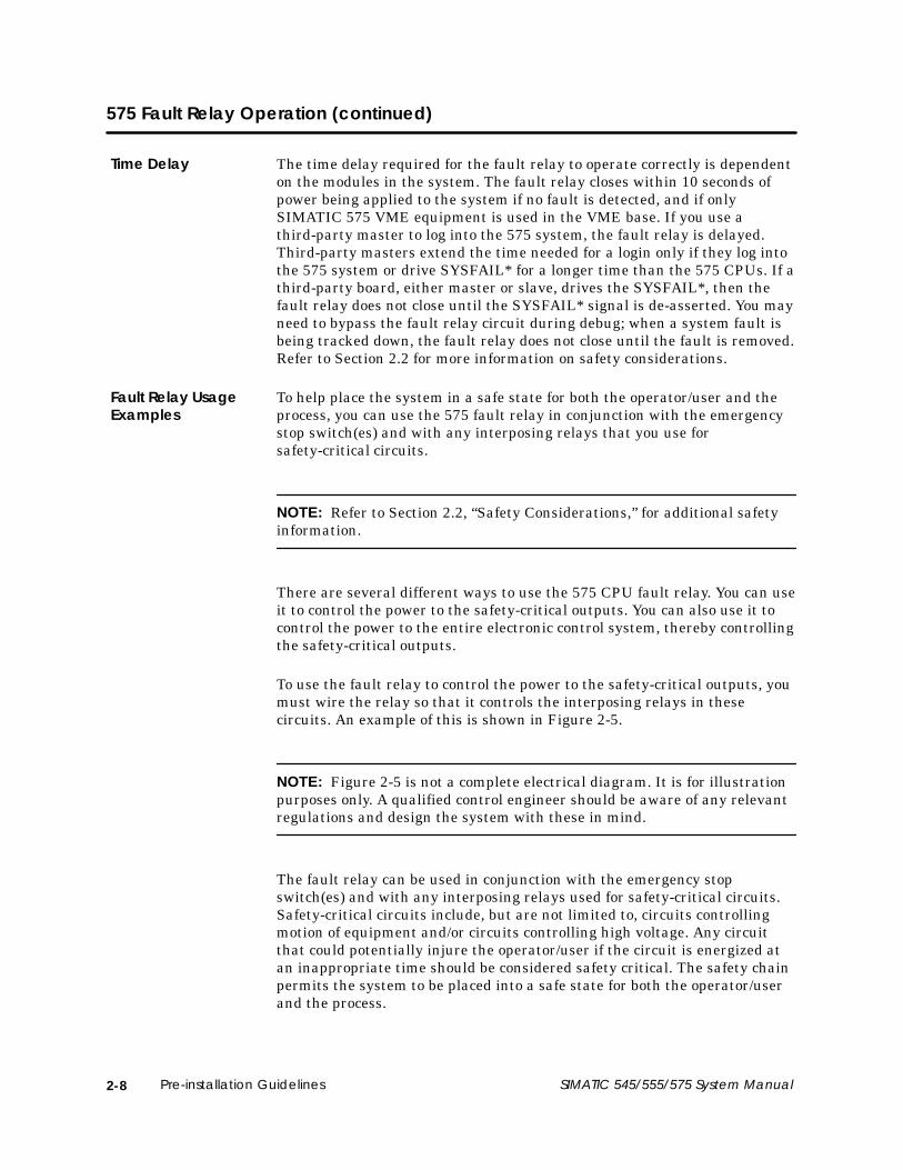
2-8 Pre-installation Guidelines SIMATIC 545/555/575 System Manual
575 Fault Relay Operation (continued)
The time delay required for the fault relay to operate correctly is dependenton the modules in the system. The fault relay closes within 10 seconds ofpower being applied to the system if no fault is detected, and if onlySIMATIC 575 VME equipment is used in the VME base. If you use athird-party master to log into the 575 system, the fault relay is delayed.Third-party masters extend the time needed for a login only if they log intothe 575 system or drive SYSFAIL* for a longer time than the 575 CPUs. If athird-party board, either master or slave, drives the SYSFAIL*, then thefault relay does not close until the SYSFAIL* signal is de-asserted. You mayneed to bypass the fault relay circuit during debug; when a system fault isbeing tracked down, the fault relay does not close until the fault is removed.Refer to Section 2.2 for more information on safety considerations.
To help place the system in a safe state for both the operator/user and theprocess, you can use the 575 fault relay in conjunction with the emergencystop switch(es) and with any interposing relays that you use forsafety-critical circuits.
NOTE: Refer to Section 2.2, “Safety Considerations,” for additional safetyinformation.
There are several different ways to use the 575 CPU fault relay. You can useit to control the power to the safety-critical outputs. You can also use it tocontrol the power to the entire electronic control system, thereby controllingthe safety-critical outputs.
To use the fault relay to control the power to the safety-critical outputs, youmust wire the relay so that it controls the interposing relays in thesecircuits. An example of this is shown in Figure 2-5.
NOTE: Figure 2-5 is not a complete electrical diagram. It is for illustrationpurposes only. A qualified control engineer should be aware of any relevantregulations and design the system with these in mind.
The fault relay can be used in conjunction with the emergency stopswitch(es) and with any interposing relays used for safety-critical circuits.Safety-critical circuits include, but are not limited to, circuits controllingmotion of equipment and/or circuits controlling high voltage. Any circuitthat could potentially injure the operator/user if the circuit is energized atan inappropriate time should be considered safety critical. The safety chainpermits the system to be placed into a safe state for both the operator/userand the process.
Time Delay
Fault Relay UsageExamples

2-9SIMATIC 545/555/575 System Manual Pre-installation Guidelines
In Figure 2-5, relay CRM is the interposing relay, and FLT is a 24-volt relay,in the low-voltage safety chain. Note the use of pushbutton switches formaster stop (normally closed) and master start (normally open). Power tothe safety-critical loads is not applied until the master start switch is turnedon. If the master stop switch is turned on, then the safety-critical loads areturned off. If one of the fault relays opens, then the safety-critical loads arealso turned off. Refer to Section 2.2 for more information on safetyconsiderations.
FLT
CRM
CRM
Master StopPB
Master StartPB
F1
F2
F3 F4 F5
P/S CPU
CPU
CPU
FLT
CRM
OutputModules
575 VME System
L1
L2
24V115V
Figure 2-5 Safety Chain Controlling Outputs Example

2-10 Pre-installation Guidelines SIMATIC 545/555/575 System Manual
575 Fault Relay Operation (continued)
To use the fault relay to control the power to the electronic control system,you must wire the relay so that it controls the interposing relays in thesupply line. An example of this is shown in Figure 2-6.
NOTE: Figure 2-6 is not a complete electrical diagram. It is for illustrationpurposes only. A qualified control engineer should be aware of any relevantregulations and design the system with these in mind.
FLT
CRM
CRM
Master StopPB
Master StartPB
F1
F2
F3 F4 F5
P/S CPU
CPU
CPU
FLT
CRM
OutputModules
575 VME System
L1
L2
24V115V
TDR TDR
CRM
Figure 2-6 Safety Chain Controlling Control System Power Example
In Figure 2-6, relay CRM is the interposing relay, and FLT is a 24-volt relayin the low-voltage safety chain. TDR is a delay-on relay with normallyclosed contacts. Note the use of pushbutton switches for master stop(normally closed) and master start (normally open). Power to the controlsystem is applied when the master start switch is actuated. If thetime-delay relay opens before the fault relay is closed, then the controlsystem loses power. If either the master stop switch is actuated or one of thefault relays opens, then the control system is turned off.

2-11SIMATIC 545/555/575 System Manual Pre-installation Guidelines
2.4 Guidelines for Fuses/Circuit Breakers
Use the following guidelines for installing fuses/circuit breakers; seeFigure 2-7. The sizes and types of fuses/circuit breakers depend on thespecified power distribution requirement.
• A circuit breaker before the isolation transformer. Isolationtransformers may not be required if your power distribution systemdoes not have a high level of noise.
• A fuse after the isolation transformer.
• An external fuse before each power supply.
Input Power Line 110/220 VAC
P/S(Line)
(Neutral)
(Ground)
Controller
Remote I/O Base
IsolationTransformer
P/S(Line)
(Neutral)
(Ground)
OptionalGrounds
Figure 2-7 Fuse/Circuit Breaker Placement
NOTE: In order to ensure a proper level of safety compliance, observe localcodes, practices, and guidelines.
Fusing theController andRemote I/O Base

2-12 Pre-installation Guidelines SIMATIC 545/555/575 System Manual
2.5 Electrical Noise
Electrical noise is defined as any unwanted electrical signal which entersthe control equipment. Noise signals cover the entire spectrum offrequencies and may have any wave shape.
A major difficulty with noise problems is that they can occur at randomintervals. Continuous or frequent, periodic noises generally are easy todetect and remedy. Intermittent noise sources that produce short,high-energy bursts at irregular and widely spaced intervals create problemsthat can be harder to resolve.
The primary sources of noise in industry are those devices (and their wiring)that produce and switch high voltage and current. Typical examples includelarge motors, welders, and contacts that switch heavily inductive loads suchas brakes or clutches.
Noise can enter your control equipment by several routes. It can beconducted through signal or power wiring or can be radiated byelectromagnetic waves. Conducted noise usually enters the system throughthe signal or power wiring. The noise may couple into the wiring byelectrostatic or magnetic means.
Electrostatic coupling occurs through parasitic capacitance between thenoisy line and the signal/power line. This requires high voltage or high rateof change voltages in the noisy line and high parasitic capacitance betweenlines. This can occur when you have long wire runs in the same conduit.
Magnetic coupling occurs through mutual inductances between lines. This isthe result of high currents or high rates of change of current, as well assignificant mutual inductance.
Electromagnetically radiated noise typically is high frequency (radio waves).The control system and its wiring may act as antennas in picking up noisesignals. This pathway is least likely to present problem levels of noise, butits sources are common in industrial applications.
Definition andSource

2-13SIMATIC 545/555/575 System Manual Pre-installation Guidelines
2.6 Correcting Noise Problems
When potential noise sources are identified, two methods are available tohandle them: noise snubbing and noise isolation. These methods aredescribed in the following sections.
Noise snubbing reduces noise at its source. Applicable only to devices drivenby mechanical contacts, snubbing suppresses the arcing at electricalcontacts that is caused by turnoff of inductive loads (e.g., relays, motors,motor starters, solenoids, etc.).
Load snubbing reduces voltage transients caused by the load, preventingthem from traveling back to the output where they would produce ashowering arc and couple with adjacent wiring. See Figure 2-8.
DiscreteOutput Load
C R
Discrete OutputModule Protection
RC snubbing
Input Power
DiscreteOutput Load
Discrete OutputModule Protection
MOV snubbing
MOV
Input Power
Figure 2-8 Load Noise Snubbing
Noise Snubbing

2-14 Pre-installation Guidelines SIMATIC 545/555/575 System Manual
Correcting Noise Problems (continued)
You can also use contact snubbing (shown in Figure 2-9) as an alternativetype of snubbing.
Both types of snubbing cause the physical devices to come on or go off moreslowly. The resistance-capacitance (RC) and metal oxide varistor (MOV)elements should have minimal effect on system timing; their time constantsare substantially less than one millisecond.
DiscreteOutput Load
CR
Discrete OutputModule Protection
RC snubbing
DiscreteOutput Load
Discrete OutputModule Protection
MOV snubbing
MOV
Input Power Input Power
Figure 2-9 Contact Noise Snubbing
NOTE: The noise snubbing shown in Figure 2-9 is built into thePPX:505–5518 relay output module.

2-15SIMATIC 545/555/575 System Manual Pre-installation Guidelines
The second approach to handling noise problems is to isolate the problemdevice and its wiring from the electronics and associated signal wiring. Youcan accomplish this by increasing the physical distance from some types ofnoisy devices. For extreme cases, electrostatic (metal) shielding may berequired. This is true for noise sources outside as well as inside themounting cabinet (NEMA-type recommended).
Two kinds of field wiring warrant special attention: wiring that enters theharsh noise area to enable monitoring and control of devices, and TTL orlow-level wiring (less than 24 V). In these cases, supplement the physicalseparation between control and noise-prone wiring with shielded,twisted-pair wiring for the control signals.
Process transmitters should normally be grounded at the transmitter end.Use a single-point shield ground, as shown in Figure 2-10.
Shielding
Twisted pair
Shielding
Transmitter
Single-point ground To controller I/O
Figure 2-10 Grounding Shielded, Twisted-Pair Cables
Noise Isolation

2-16 Pre-installation Guidelines SIMATIC 545/555/575 System Manual
2.7 Wiring Guidelines
Consider the following guidelines before installing any system or powerwiring:
• Always use the shortest possible single-length cable.
• Avoid placing system and field wiring in the vicinity of high-energyand/or high-frequency wiring.
• Keep field input wiring, output wiring, and all other types of wiring inthe panel physically separated when possible.
• Separate DC field wiring from AC field wiring wherever possible.
• Avoid sharp bends to power and data cables. Use 3 in. (76 mm) radius,minimum, on all bends.
• Ensure that a good low earth ground impedance of 0.1 ohm or lessexists for all components in the system.
• Use metal wireways and conduit when possible.
• Keep wire strippings from falling into modules, CPUs, or bases.
• Use separate wires for long return lines to the power supply—do notuse the same wire for input and output modules. Using separate returnwiring for these modules minimizes the voltage drop on the return linesof the input connections.

2-17SIMATIC 545/555/575 System Manual Pre-installation Guidelines
2.8 Grounding the Power System
! WARNINGA good grounding system is essential for proper operation of the system. It isone of the most important considerations in planning your installation.
Failure to provide a good grounding system could lead to erratic operation ofthe equipment, which could result in death or serious injury to personnel,and/or damage to equipment.
Ensure that you have a good grounding system when you install yourequipment.
In some installations, a metal conduit that connects to the neutral phase atthe circuit-breaker box supplies the earth ground of the power receptacle.Depending on site conditions, this metal conduit could conduct current fromother sources that can interfere with the operation of the equipment.
To reduce this possibility, isolate earth ground and neutral from the conduit(except at the service entrance housing); see Figure 2-11. Ensure thatsystem power is wired in accordance with NEMA specifications. Also complywith the following:
• Ensure that the protective ground wire resistance is less than 0.1 ohm.
• Ensure that the resistance to earth ground is 0.1 ohm or less.
Conduit Conduit
Protectiveground
Circuitbreakerpanel
Basepower supply
AC line
AC neutral
Ground
Serviceentrance
Powercompanytransformer
Powercompanyearth ground
Earthground rod
Figure 2-11 Isolating Ground and Neutral From Conduit
Earth Ground

2-18 Pre-installation Guidelines SIMATIC 545/555/575 System Manual
Grounding the Power System (continued)
Use particular care when establishing the ground connections. Thefollowing techniques will help to establish good electrical connections anddecrease noise interference:
• Where possible, terminate grounding braid and green wires at bothends with copper eye lugs to provide a good contact surface. Lugsshould be crimped and soldered.
• Use #10 copper bolts (or equivalent) for those fasteners providingelectrical connections to the single-point ground. This applies todevice-mounting bolts and braid termination bolts for subpanel anduser-supplied single points. Tapped holes for these fasteners are betterthan nut-bolt arrangements.
• Paints, coatings, and corrosion can prevent good electrical contact atground points. Remove these impediments in the area of contact anduse external toothed lock washers (star washers) to ensure goodcontinuity and low impedance. This practice should be used for allterminations—lug to subpanel, device to lug, device to subpanel,subpanel to conduit, etc. Examples of ground connections are shown inFigure 2-12.
Starwashers
Equipment Subpanel
Step 1
Step 3Step 2
Step 1
Step 2
To ground equipment directly to the sub-panel,follow these steps:
1. Remove the finish from the equipment atareas of contact.
2. Tighten the first nut.
3. Tighten the second nut.
You may need a lock washer to prevent the nutin Step 3 from backing off.
To attach ground leads to the sub-panel,follow these steps:
1. Remove the finish from the equipment atareas of contact.
2. Tighten the bolt.
Subpanelor user-suppliedsingle-point ground
Starwashers
Ground braidcopper lugs
Figure 2-12 Example of Ground Connections
GroundConnections

2-19SIMATIC 545/555/575 System Manual Pre-installation Guidelines
Ground your 545/555 controller by following the guidelines below to ensurethat noise is minimized.
• Use the ground connection (Figure 2-13) to attach one end of a groundwire; attach the other end to a nearby grounding rod that meets allelectrical specifications required for an earth ground.
• Use the shortest possible length of #8-gauge copper wire, or equivalentbraided cable, to make the connection.
G
G
Figure 2-13 Grounding the 545/555 Controller Chassis
If the system is mounted in a cabinet or rack, use the same groundingprocedure. Ensure that a good cabinet or rack ground connection is achievedby removing existing paint and attaching a #8 gauge copper wire (orequivalent) using a bolt, washers, and nut as necessary.
Grounding the545/555 ControllerChassis
Grounding theCabinet or Rack

2-20 Pre-installation Guidelines SIMATIC 545/555/575 System Manual
Grounding the Power System (continued)
Cabling at the rear of the unit can be routed in and out of the cabinetthrough the two cable ducts at the bottom of the unit or by removing thebreak-away tab on the rear panel. (Refer to Figure 4-31 for location of thebreak-away tab.)
A ground connector mounted on the side panel of the chassis provides anearth-ground connection to the chassis. For an alternate location, you canmove the ground lug to the rear mounting bracket, as shown in Figure 2-14.
GroundLug
OptionalMountingLocation
RearMountingBracket
Figure 2-14 Grounding Connection and Alternate Location
Use the ground connection (Figure 2-14) to attach one end of a ground wire;attach the other end to a nearby grounding rod that meets all electricalspecifications required for an earth ground. Use the shortest possible lengthof #8 gauge copper wire, or equivalent braided cable, to make theconnection.
If the system is mounted in a cabinet or rack, use the same groundingprocedure. Ensure that a good cabinet or rack ground connection is achievedby removing existing paint and attaching a #8 gauge copper wire (orequivalent) using a bolt, washers, and nut as necessary.
CableManagement forthe 575
Grounding the 575Controller Chassis
Grounding theCabinet or Rack

3-1SIMATIC 545/555/575 System Manual Installing 505 System Hardware
Chapter 3
Installing 505 System Hardware
3.1 Overview of Installation Procedures 3-2. . . . . . . . . . . . . . . . . . . . . . . . . . . . . . . . . . . . . . . . . . . . . .
3.2 Enclosure and Temperature Considerations 3-3. . . . . . . . . . . . . . . . . . . . . . . . . . . . . . . . . . . . . . Enclosure Selection 3-3. . . . . . . . . . . . . . . . . . . . . . . . . . . . . . . . . . . . . . . . . . . . . . . . . . . . . . . . . . . . . Temperature Considerations 3-3. . . . . . . . . . . . . . . . . . . . . . . . . . . . . . . . . . . . . . . . . . . . . . . . . . . . .
3.3 Series 505 Bases 3-4. . . . . . . . . . . . . . . . . . . . . . . . . . . . . . . . . . . . . . . . . . . . . . . . . . . . . . . . . . . . . . . . Description 3-4. . . . . . . . . . . . . . . . . . . . . . . . . . . . . . . . . . . . . . . . . . . . . . . . . . . . . . . . . . . . . . . . . . . . . Grounding the Controller Chassis 3-4. . . . . . . . . . . . . . . . . . . . . . . . . . . . . . . . . . . . . . . . . . . . . . . .
3.4 Rack Mounting Series 505 Bases 3-5. . . . . . . . . . . . . . . . . . . . . . . . . . . . . . . . . . . . . . . . . . . . . . . . .
3.5 Panel Mounting Series 505 Bases 3-6. . . . . . . . . . . . . . . . . . . . . . . . . . . . . . . . . . . . . . . . . . . . . . . . .
3.6 Installing Series 505 Power Supply 3-8. . . . . . . . . . . . . . . . . . . . . . . . . . . . . . . . . . . . . . . . . . . . . . . . Power Budget for Series 505 Base 3-8. . . . . . . . . . . . . . . . . . . . . . . . . . . . . . . . . . . . . . . . . . . . . . . . Power Supply Placement in Bases 3-8. . . . . . . . . . . . . . . . . . . . . . . . . . . . . . . . . . . . . . . . . . . . . . . . Installing and Removing the Power Supply 3-8. . . . . . . . . . . . . . . . . . . . . . . . . . . . . . . . . . . . . . . Wiring the Power Supply 3-10. . . . . . . . . . . . . . . . . . . . . . . . . . . . . . . . . . . . . . . . . . . . . . . . . . . . . . . . .
3.7 Installing the PROFIBUS-DP Annex Card (Optional) 3-12. . . . . . . . . . . . . . . . . . . . . . . . . . . . . . . .
3.8 Installing the 545/555 CPU 3-14. . . . . . . . . . . . . . . . . . . . . . . . . . . . . . . . . . . . . . . . . . . . . . . . . . . . . . . CPU/RBC Location in a Base 3-14. . . . . . . . . . . . . . . . . . . . . . . . . . . . . . . . . . . . . . . . . . . . . . . . . . . . . Installing and Removing the CPU 3-14. . . . . . . . . . . . . . . . . . . . . . . . . . . . . . . . . . . . . . . . . . . . . . . .
3.9 Replacing and Handling the Battery 3-16. . . . . . . . . . . . . . . . . . . . . . . . . . . . . . . . . . . . . . . . . . . . . Lithium Battery in the 545 and 555 –1105/–1106 CPUs 3-16. . . . . . . . . . . . . . . . . . . . . . . . . . . . . . Replacing the Battery in –1105/–1106 CPUs 3-17. . . . . . . . . . . . . . . . . . . . . . . . . . . . . . . . . . . . . . . Lithium Battery in the 545 and 555 –1103/–1104 CPUs 3-18. . . . . . . . . . . . . . . . . . . . . . . . . . . . . . Indicators 3-18. . . . . . . . . . . . . . . . . . . . . . . . . . . . . . . . . . . . . . . . . . . . . . . . . . . . . . . . . . . . . . . . . . . . . . Using and Handling Batteries 3-19. . . . . . . . . . . . . . . . . . . . . . . . . . . . . . . . . . . . . . . . . . . . . . . . . . . . Transporting Batteries 3-19. . . . . . . . . . . . . . . . . . . . . . . . . . . . . . . . . . . . . . . . . . . . . . . . . . . . . . . . . . . Storing Batteries 3-19. . . . . . . . . . . . . . . . . . . . . . . . . . . . . . . . . . . . . . . . . . . . . . . . . . . . . . . . . . . . . . . . Discarding Batteries 3-19. . . . . . . . . . . . . . . . . . . . . . . . . . . . . . . . . . . . . . . . . . . . . . . . . . . . . . . . . . . . . Replacing the Battery in –1103/–1104 CPUs 3-20. . . . . . . . . . . . . . . . . . . . . . . . . . . . . . . . . . . . . . .
3.10 Setting the CPU Dipswitches 3-22. . . . . . . . . . . . . . . . . . . . . . . . . . . . . . . . . . . . . . . . . . . . . . . . . . . . . Dipswitch Location and Settings 3-22. . . . . . . . . . . . . . . . . . . . . . . . . . . . . . . . . . . . . . . . . . . . . . . . . Enabling Battery Backup 3-22. . . . . . . . . . . . . . . . . . . . . . . . . . . . . . . . . . . . . . . . . . . . . . . . . . . . . . . . Enabling the Auto Recompile Function 3-22. . . . . . . . . . . . . . . . . . . . . . . . . . . . . . . . . . . . . . . . . . . Setting Baud Rates 3-23. . . . . . . . . . . . . . . . . . . . . . . . . . . . . . . . . . . . . . . . . . . . . . . . . . . . . . . . . . . . . . Communications Port 1 3-24. . . . . . . . . . . . . . . . . . . . . . . . . . . . . . . . . . . . . . . . . . . . . . . . . . . . . . . . . Communications Port 2 3-24. . . . . . . . . . . . . . . . . . . . . . . . . . . . . . . . . . . . . . . . . . . . . . . . . . . . . . . . . I/O Ports 3-25. . . . . . . . . . . . . . . . . . . . . . . . . . . . . . . . . . . . . . . . . . . . . . . . . . . . . . . . . . . . . . . . . . . . . . . .
3.11 Installing Series 505 I/O Modules 3-26. . . . . . . . . . . . . . . . . . . . . . . . . . . . . . . . . . . . . . . . . . . . . . . . . Mixing I/O Modules 3-26. . . . . . . . . . . . . . . . . . . . . . . . . . . . . . . . . . . . . . . . . . . . . . . . . . . . . . . . . . . . . Installing and Removing I/O Modules 3-26. . . . . . . . . . . . . . . . . . . . . . . . . . . . . . . . . . . . . . . . . . . .

3-2 Installing 505 System Hardware SIMATIC 545/555/575 System Manual
3.1 Overview of Installation Procedures
The following charts identify the tasks for installing Series 505 systemhardware.
Install Base
• Rack mounting • Panel mounting
Install Power Supply
Install 545/555 CPU
Install I/O Modules
(Optional) Install Annex Card 1
To install a CPU:
Install Base
• Rack mounting • Panel mounting
Install Power Supply
Install RBC 2
Install I/O Modules
To install an RBC:
1 The PROFIBUS-DP annex card (PPX:505–CP5434–DP) is a user-installed option for the 545–1103/–1105 CPU.
2 Chapter 5 describes the RBCs which can be installed in Series 505 bases.

3-3SIMATIC 545/555/575 System Manual Installing 505 System Hardware
3.2 Enclosure and Temperature Considerations
An enclosure should provide the following features:
• Easy access to components.
• A common ground potential on the cabinet.
• A secure vertical panel or rails.
• Conformance to electrical standards.
• An electromagnetic shield, if needed to meet FCC or CE emissionstandards.
• Access restricted to authorized personnel only.
• Adequate cooling and heat dissipation.
• Protection from dust and dirt as required by the environment.
Mount the components in a dustproof and drip-tight enclosure, such as aNEMA enclosure. The enclosure must provide a minimum depth of10 inches (254 mm) from the panel to the inside surface of the enclosuredoor. The enclosure should be located so that the doors can be opened fully,permitting easy access to the controller, wiring, and components. Ifenvironmental conditions permit, a 19-inch rack may be used instead of aNEMA enclosure. Use either the 11-slot PPX:505–6511 or the 16-slotPPX:505–6516 base for 19-inch rack installations.
The SIMATIC 505/575 PLC Systems comply with the requirements of theEMC Directive 89/336/EEC when installed in accordance with thespecifications in this manual and when installed in a grounded metalcabinet with tightly sealed doors. If Series 505 Remote I/O channel cables toremote bases are run outside the cabinet, they must either be run in a fullyenclosed metal raceway or fitted with ferrite beads where they leave and/orenter the cabinets. Ferrites shall be Steward PN 28-A-2029-0 or equivalent.
When preparing your installation, plan for an adequate air flow to ensureproper cooling of equipment. Do not permit the convection cooling of thecontroller to be hindered. Unless ambient temperatures are extremely high,a fan or air-conditioned cooling is unnecessary for keeping controllers belowtheir maximum-rated operating temperature of 60°C, provided that thecabinet adequately dissipates heat.
For one local base and one remote base located in the bottom half of a 7-foot,19-inch rack, you can place equipment that dissipates no more than 325 Win the top half, above the Series 505 bases, assuming a 25°C externalambient temperature. If you must exceed these guidelines, or if the base isnot installed with the vent screens at top and bottom positions, use coolingequipment to lower the equipment temperature to the recommended level.
Enclosure Selection
TemperatureConsiderations

3-4 Installing 505 System Hardware SIMATIC 545/555/575 System Manual
3.3 Series 505 Bases
The 545/555 CPU is housed in a Series 505 base. A base has slots for thepower supply, the CPU or RBC, and the I/O modules. Four base models arecurrently available; see Table 3-1.
Table 3-1 Series 505 Base Models
Model Number of I/OSlots
Support forRedundancy
Mounting
PPX:505–6504 4 No NEMA panel
PPX:505–6508 8 No NEMA panel
PPX:505–6511 11 Yes1 NEMA panel or rack
PPX:505–6516 16 No NEMA panel or rack1The PPX:505–6511 base supports redundant power supplies and/or redundant RBCs. ThePPX:505–6660-A (or -B) and the PPX:505–6663 (or -A) power supplies can be used in either aredundant or a non-redundant configuration. You do not have to use redundant RBCs withdual power supplies; you can use a single RBC, or a single CPU.
A good grounding system is essential for proper operation of the system.Follow the guidelines in Section 2.8 to ensure that the Series 505 base isproperly grounded.
Description
Grounding theController Chassis

3-5SIMATIC 545/555/575 System Manual Installing 505 System Hardware
3.4 Rack Mounting Series 505 Bases
Use the following steps for mounting a PPX:505–6511 or PPX:505–6516base in a standard 19-inch rack. See Figure 3-1.
1. Move brackets from wall-mounting position (back of chassis) to frontposition.
2. Position the base in the 19-inch rack. Depth of base is 8 inches(205 mm).
NOTE: There should be at least 6 inches (150 mm) of clearance at the topand bottom of the base for adequate airflow.
3. Align two bracket slots with two screw holes located on each side of the19-inch rack.
4. Secure each bracket to the 19-inch rack with two screws installedthrough the bracket slots.
Figure 3-1 Mounting Base to Standard 19-inch Rack

3-6 Installing 505 System Hardware SIMATIC 545/555/575 System Manual
3.5 Panel Mounting Series 505 Bases
Use the following steps for panel mounting in an NEMA enclosure.
NOTE: There should be at least 6 inches (150 mm) of clearance at the topand bottom of base for adequate airflow. The base depth is 7.99 inches(203 mm).
1. Open NEMA enclosure door.
2. Drill four holes in sub-panel of NEMA enclosure with a #21 drill bit.Refer to Table 3-2 for screw-hole dimensions for each base.
Ensure that chips from drilling do not contaminate other equipment.
3. Tap the drilled holes with a #10-32 tap.
4. Position the base inside the NEMA enclosure.
NOTE: Be sure that the bracket holes and the tapped holes in the sub-panelare aligned.
5. Install #10 screws through each bracket hole to attach the base to thesub-panel. See Figure 3-2.
Figure 3-2 Mounting Base in NEMA Enclosure

3-7SIMATIC 545/555/575 System Manual Installing 505 System Hardware
Table 3-2 Series 505 Base Dimensions
0.85(22)
A
10.47(266)
8.97(228)
1.47(37)
BMeasurements:in.
(mm)
Siemens
PPX:505–6504PPX:505–6508PPX:505–6511PPX:505–6516
PROFIBUS-DP
0.85(22)
Base PPX: Dimension A inches/(mm) Dimension B inches/(mm)
505–6504 8.10 (206) 8.69 (221)
505–6508 11.29 (287) 11.93 (303)
505–6511 17.70 (450) 18.34 (466)
505–6516 17.70 (450) 18.34 (466)

3-8 Installing 505 System Hardware SIMATIC 545/555/575 System Manual
3.6 Installing Series 505 Power Supply
The total power consumption of all I/O modules (including the CPU or RBC)drawing power from a Series 505 power supply must not exceed 55.0 W fromthe +5 VDC output and 3.75 W from the –5 VDC output. Refer toAppendix B for power consumption listings for the CPU and all currentlyavailable Series 505 I/O modules and RBCs.
Figure 3-3 shows the placement of the power supply in Series 505 bases.The power supply must always be installed in the left-most slot.
I/O
I/O
I/O
I/O
CPU/RBC
I/O
I/O
I/O
I/O
P/S
Figure 3-3 Placement of Power Supply in Series 505 Base
Use the following steps to install or remove a PPX:505–6660,PPX:505–6660–A, or PPX:505–6663 power supply.
! WARNINGDo not install or remove any modules to or from a powered-up base.
Installing or removing any module from a powered-up base could causeunexpected operation which could cause death or serious injury to personnel,and/or damage to equipment.
Disable all power to the base before installing or removing any module.
1. Disconnect power to the base.
CAUTIONAttempting to operate the PPX:505–6660 or PPX:505–6660–A power supply at220 VAC with 110 VAC selected, or 110 VAC with 220 VAC selected, results indamage to power supply. Attempting to operate the PPX:505–6663 powersupply outside the designed voltage range of 20 to 30 VDC may cause damageto the power supply.
Double-check your power supply voltage before you attempt operation.
Power Budget forSeries 505 Base
Power SupplyPlacement in Bases
Installing andRemoving thePower Supply

3-9SIMATIC 545/555/575 System Manual Installing 505 System Hardware
2. If you are installing the PPX:505–6660 or PPX:505–6660–A or –Bpower supply, connect the voltage selector as shown in Figure 3-4.
220 V 110 V
TAB1TAB2
220V110V
Selecting voltage for thePPX:505–6660 power supply.
Selecting voltage for thePPX:505–6660–Apower supply.
JP5JP3
220V110V
Selecting voltage for thePPX:505–6660–B power supply.
Figure 3-4 Input Voltage Selectors
3. Position the power supply so that the bezel is facing you.
4. Grasp the top and bottom of the power supply.
5. Carefully push the power supply into the slot until it mates with thebackplane connectors.
6. Tighten top and bottom bezel screw to between 2.6 in–lb (0.3 N–m) and5.2 in–lb (0.6 N–m) torque.
To remove the Series 505 power supply, simply reverse the procedures usedduring installation.

3-10 Installing 505 System Hardware SIMATIC 545/555/575 System Manual
Installing Series 505 Power Supply (continued)
After installing the power supply, you are ready to connect your powersupply to an external power source. Observe these guidelines as you carryout the procedure below.
• Use 14 to 22 AWG solid or stranded wire. If you use stranded wire, thewire should be twisted and trimmed.
• Strip insulation back 0.4 inches (10 mm).
• Insert the wires fully into the terminal block so that the insulationbutts against the block.
NOTE: The connector is rated for 50 wire insertions at no more than 5 in–lb(0.56 N–m) torque.
! WARNINGElectrical shock hazard is possible if you do not turn off all power beforeattempting the wiring procedure.
Failure to turn off power could cause death or serious injury to personnel,and/or damage to equipment.
Ensure that all power is disabled before attempting the wiring procedures.
1. Disconnect power to the base.
2. Loosen the three power connector screws.
! CAUTIONThe PPX:505–6660 and PPX:505–6660–A power supplies have selectablevoltage. Ensure that the voltage selector is set to match the input power. SeeFigure 3-4 for an example of how to set the voltage selector.
Attempting to operate the power supply at 220 VAC with 110 VAC selected, or110 VAC with 220 VAC selected, results in damage to the power supply.
Double-check your power supply voltage before you connect input power.
Wiring the PowerSupply

3-11SIMATIC 545/555/575 System Manual Installing 505 System Hardware
3. Insert wires as appropriate for your power supply module, and tightenscrews to no more than 5 in–lb (0.56 N–m) torque. Figure 3-5 shows thelocation of the power connector screws on the module. (Consult Section2.8 for grounding guidelines.)
DC POWER GOOD
AC LINEAC NEUTRALGROUND
Siemens
SIMATIC505
Power connectorscrews
505-6660
Figure 3-5 Series 505 Power Connector
4. If you have the PPX:505–6663 power supply, insert the chassis ground,DC–, and DC+ line wires into the socket on the power supply. Thispower supply requires 24 VDC.

3-12 Installing 505 System Hardware SIMATIC 545/555/575 System Manual
3.7 Installing the PROFIBUS-DP Annex Card (Optional)
To install the PROFIBUS-DP annex card, PPX:505–CP5434–DP, on a545–1103 or 545–1105 CPU, follow the procedure described below andconsult Figure 3-6.
1. Carefully set your CPU board on a static-dissipative surface.
CAUTIONElectronic equipment is sensitive to, and can be damaged by, electrostaticdischarge.
Ensure that personnel make contact with a static-dissipative pad and/or wear agrounded wrist strap when handling the CPU cards or modules.
2. Remove the PROFIBUS-DP port cover from the bezel. The port cover isnot reusable.
The port cover is secured by plastic pins that project through the bezeland are secured on the back side by clamps. First clip the pins off asclose to the clamps as practicable; then pry the clamps loose andremove the port cover.
3. To attach the annex card to the CPU board, insert the 9-pinD-connector of the annex card into the CPU bezel opening and align theannex connector with the connector on the CPU. Apply pressure untilthe connectors are mated.
4. Insert metal screws (supplied) into the screw-holes of thePROFIBUS-DP communication port and tighten to a maximum of5.2 in–lb (0.6 N–m) torque.
5. Insert plastic screws (supplied) through the CPU into the annex cardstandoffs and tighten.

3-13SIMATIC 545/555/575 System Manual Installing 505 System Hardware
SIMATIC545
545–1105
CPU GOOD
RUN
BATT GOOD
PROFIBUS-DP Dipswitch
Figure 3-6 Installing the PROFIBUS-DP Annex Card in 545–1103/–1105 CPU

3-14 Installing 505 System Hardware SIMATIC 545/555/575 System Manual
3.8 Installing the 545/555 CPU
The second slot from the left (beside the power supply module) is reserved inSeries 505 bases for the CPU or RBC, as shown in Figure 3-7.
I/O
I/O
I/O
I/O
I/O
I/O
I/O
I/O
P/S
CPU/RBC
Figure 3-7 Location of CPU/RBC in a Series 505 Base
Refer to Figure 3-8 and follow the steps below to install the 545/555 CPU.
! WARNINGInstalling or removing a CPU from a powered-up base disrupts your process.
Disruption of your process can cause death or serious injury to personnel,and/or damage to equipment.
Ensure that all power is disabled before installing or removing the CPU.
1. Disconnect power to the base.
2. Position the CPU so that the bezel is facing you.
CAUTIONElectronic equipment is sensitive to, and can be damaged by, electrostaticdischarge.
Ensure that personnel make contact with a static-dissipative pad and/or wear agrounded wrist strap when handling the CPU cards or modules.
3. Grasp the top and bottom of the CPU module.
CPU/RBC Locationin a Base
Installing andRemoving the CPU

3-15SIMATIC 545/555/575 System Manual Installing 505 System Hardware
4. Carefully push the module into the slot until it mates with thebackplane connectors.
5. Tighten top and bottom bezel screws.
Minimum torque: 2.6 in–lb (0.3 N–m)
Maximum torque: 5.2 in–lb (0.6 N–m)
Figure 3-8 Installing CPU Module in a Series 505 Base
To remove the CPU, complete the following steps.
1. If cables are attached, remove them from the front of the CPU.
2. Disconnect power to the base.
3. Loosen top and bottom bezel screws.
4. Carefully pull the CPU from the base.

3-16 Installing 505 System Hardware SIMATIC 545/555/575 System Manual
3.9 Replacing and Handling the Battery
The 545–1105/1106 and 555–1105/1106 CPUs use a lithium battery formaintaining CPU memory contents while power is not present. The lithiumbattery is a primary cell; it is not rechargeable. The battery in these CPUmodels is accessible through the bezel door on the front of the module, asshown in Figure 3-9.
When the battery indicator blinks or goes off, the battery has dropped belowthe voltage required to maintain memory and should be replaced. Requestbattery kit replacement part number PPX:2587678-8005 for the appropriatereplacement battery. Refer to page 3-19 for guidelines on handling batteries.
NOTE: As a good engineering practice, design your user program to monitorStatus Word 01 on a cyclic basis and trigger an alarm if the battery-low bit(15) is set. Additionally, you can use the battery life specifications listed inTable A-2 to determine how often you routinely replace the battery.
Replaceable Lithium Battery
Figure 3-9 Battery Location in –1105 and –1106 CPU Modules
Lithium Battery inthe 545 and 555–1105/–1106 CPUs

3-17SIMATIC 545/555/575 System Manual Installing 505 System Hardware
Follow these steps to replace the battery:
1. Maintain power to the CPU.
2. Open the battery cover.
3. Pull out the old battery and disconnect the battery connectors.
4. Connect the battery connectors to the replacement battery.
5. Place the new battery in the battery compartment, making sure theconnecting wires are fully inserted through the holes in thecompartment, and close the cover.
6. Check the BATT GOOD indicator on the CPU to make sure that itlights back up to confirm that the replacement battery is good.
Front Bezel
BatteryCover
Battery
Battery Connectors
Figure 3-10 Replacing the Battery in –1105 and –1106 CPU Modules
Replacing theBattery in–1105/–1106 CPUs

3-18 Installing 505 System Hardware SIMATIC 545/555/575 System Manual
Replacing and Handling the Battery (continued)
The 545–1103/1104 and 555–1103/1104 CPUs use a lithium coin battery formaintaining CPU memory contents while power is not present. The batteryis a Panasonic BR2325, PPX:2587678–8010, or equivalent, 23 mm diameter,with a nominal capacity of 165 mAh. The lithium battery is a primary cell;it is not rechargeable. Figure 3-11 shows the location of the battery on theCPU card.
EEPROM
ReplaceableLithium Battery
Battery Clip
Battery Socket
Figure 3-11 Battery Location on 545/555 CPU Modules
A fresh battery can typically maintain your system with power off for threemonths at room temperature, or a substantially shorter time at elevatedtemperatures. The battery indicator is illuminated as long as power ispresent and the battery voltage is adequate for maintaining the memory;however, the indicator does not show the amount of battery life remaining.When the battery indicator blinks or goes off, the battery has dropped belowthe voltage required to maintain memory and should be replaced. See page3-20, “Replacing the Battery.”
! WARNINGCharging a primary lithium battery can cause the battery to explode.
An exploding lithium battery can result in death or serious injury to personnel,and/or damage to equipment.
Do not attempt to charge primary lithium batteries. Instead, replace your batteryfollowing the procedure on page 3-20, and dispose of the battery according tothe instructions of its manufacturer.
Lithium Battery inthe 545 and 555–1103/–1104 CPUs
Indicators

3-19SIMATIC 545/555/575 System Manual Installing 505 System Hardware
Use the following safety instructions to minimize the risk of personal injuryor fire hazard when handling lithium batteries.
Lithium batteries contain flammable material. Do not open, puncture, orcrush the battery case. Puncturing the battery case releases electrolyte andpotentially flammable material. Exposure to electrolyte can cause throatand/or eye irritation. If the electrolyte comes in contact with your skin oreyes, flush the area thoroughly with large amounts of water.
Never use a lithium battery in a completely sealed container. Containersmust have a mechanism for relieving pressure if the battery is exposed tohigh temperature or abuse.
If a lithium battery short-circuits, disconnect it immediately and move it toa well-ventilated area. Wear safety glasses and other protective gear whenhandling a disabled battery.
Transportation of lithium batteries is regulated by the U.S. Department ofTransportation. Lithium batteries must be shipped under exemptionDOT–E 7502.
• For international shipments, IATA Regulation 2294 applies.
• Lithium batteries such as the one used in the 545 and 555 CPUs, whichcontains less than 0.5 grams of lithium, are not restricted in shipment,according to DOT 173.206 (f) or IATA Section X.
Take precautions in storing batteries.
• Do not place batteries on a metal surface; doing so could cause apotential short circuit.
• Do not store batteries loosely or in dump bins. Store batteries in theoriginal shipping container.
• Store batteries in a cool, well-ventilated area with a maximumtemperature of 70°C (158°F).
Batteries to be discarded may contain a significant amount of unusedenergy. They must be packed for disposal and isolated electrically. Batteriesmust be disposed of in accordance with all local, state and federalregulations.
Using and HandlingBatteries
TransportingBatteries
Storing Batteries
DiscardingBatteries

3-20 Installing 505 System Hardware SIMATIC 545/555/575 System Manual
Replacing and Handling the Battery (continued)
ATTENTION: Danger of explosion if battery is incorrectly replaced. Replaceonly with the same or equivalent type recommended by the manufacturer.Discard used batteries according to the manufacturer’s instructions.
ATTENTION: Il y a danger d’explosion s’il y a remplacement incorrect de labatterie. Remplacer uniquement avec une batterie du même type ou d’un typerecommandé par le constructeur. Mettre au rebut les batteries usagéesconformement aux instructions du fabricant.*
* Canadian standard CAN/CSA C22.2, No. 950–M89
Battery changes require advance planning. For the 545–1103/1104 and555–1103/1104 CPUs, keep the following guidelines in mind:
• In order to change the lithium battery, you must power down thesystem.
• Memory can be lost if system power is removed from the CPU forlonger than twenty minutes during a battery change.
• A good battery must be in place when power is restored, or else theCPU goes through a battery-bad powerup and all memory is lost.
NOTE: As a safeguard, consider using SoftShop, TISOFT, or APT to saveyour program before you replace the battery.
Follow these steps to replace the lithium battery:
1. Place your process in a safe state.
! WARNINGInstalling or removing a CPU from a powered-up base disrupts your process.
Disruption of your process can cause death or serious injury to personnel,and/or damage to equipment.
Ensure that all power is disabled before installing or removing the CPU.
2. Disconnect power from the chassis.
At room temperature, you have approximately twenty minutes toreplace the battery after power is removed from the CPU.
If the CPU detects a bad battery before power is either removed or lost(e.g., power failure), you must replace the battery before restoringpower, or lose memory contents.
Replacing theBattery in–1103/–1104 CPUs

3-21SIMATIC 545/555/575 System Manual Installing 505 System Hardware
3. Remove the CPU from the chassis and place the CPU, component-sideup, on a static-dissipative surface.
The components in the CPU card can be degraded or destroyed byelectrostatic discharge (ESD). Follow proper handling precautions inorder to prevent ESD damage.
4. Remove the battery from the socket, observing the followingprecautions:
! WARNINGThe terminals of the lithium coin cell are extremely close together. In the courseof removing the battery, it is possible for you to short the battery.
Shorting the battery presents the danger of explosion and/or hightemperatures, and could cause death or serious injury to personnel, and/ordamage to equipment.
Follow the instructions given below in order to avoid shorting the battery.
• Use a non-conductive implement when removing the battery fromthe socket. Do not allow a conductive device (for example, a metalscrewdriver blade) to contact both sides of the batterysimultaneously. Since the battery is shaped like a coin, it is easyfor the screwdriver blade to make contact with both rim andunderside, which would cause a short.
CAUTIONThe positive contact of the battery socket is a thin metal strip, easily bent.
If you deform the positive contact of the socket, the socket is ruined.
Extract the battery gently so that you do not overflex the socket. Follow theinstructions given below.
• If you pull the battery straight up from the socket, you couldspring the positive contact and ruin the socket. Instead, lift thebattery up to the height of the socket rim and carefully slide it out,making certain you do not bend the socket’s positive contact.
5. Slide a fresh battery into the socket, being careful to observe polarity.
The battery and the socket are both marked with plus signs (+),indicating positive contacts. The positive contact is the upper contact.
6. Reinstall the CPU in the chassis.
7. Ensure the battery is enabled (SW9 is set to On). (See page 3-22.)
8. Restore power to the chassis.

3-22 Installing 505 System Hardware SIMATIC 545/555/575 System Manual
3.10 Setting the CPU Dipswitches
Dipswitches are used to set 545/555 CPU operating parameters. Thedipswitches are located near the front of the CPU, behind the bezel orbattery door. See Figure 3-12. To gain access, lower the access door. With theCPU in its (normal) vertical position, dipswitches pushed to the left are On;dipswitches pushed to the right are Off.
Dipswitch
Port 2 = RS-485Port 2 = RS-232/422
Port 1 = Programming port Port 1 = Printer port
Port 1 Baud rate
Port 2 Baud rate
Battery OffBattery On
Auto Recompile On*
0 (Off)(On) 1
Auto Recompile Off*
* The Auto Recompile option is available on CPUmodels 555–1103/–1104 Release 4.2 or greater,models 555–1105/–1106 Release 5.2 or greater, andmodels 545–1105/–1106 Release 5.1 or greater.
Figure 3-12 545/555 CPU Dipswitch Location
Switch 9 is used to set the back-up battery On or Off. As Figure 3-12indicates, moving the switch to the left enables the back-up battery; settingthe switch to the right disables the back-up battery.
NOTE: When SW9 is set to the On position, the battery LED indicates thestate of the battery back-up circuit. If the battery LED is illuminated,memory contents should be maintained; if the LED is not illuminated,memory contents will not be maintained.
Switch 10 is used to allow the CPU to perform an Auto Recompile duringruntime. Switch 10 is shipped in the disabled (left) position. To activate thisfeature, set the switch to the right (enabled) position. Refer to Appendix Ffor more information about the Auto Recompile function.
Dipswitch Locationand Settings
Enabling BatteryBackup
Enabling theAuto RecompileFunction

3-23SIMATIC 545/555/575 System Manual Installing 505 System Hardware
Switches 3 through 8 are used to set baud rates for Ports 1 and 2. Switches3, 4, and 5 set Port 1 baud rates. See Table 3-3. Switches 6, 7, and 8 set Port2 baud rates. See Table 3-4.
Table 3-3 Port 1 Baud Rate Settings
Baud Rate SW3 SW4 SW5
1152001 1 (On) 1 (On) 0 (Off)
576001 1 (On) 0 (Off) 1 (On)
38400 1 (On) 0 (Off) 0 (Off)
19200 1 (On) 1 (On) 1 (On)
9600 0 (Off) 1 (On) 1 (On)
2400 0 (Off) 0 (Off) 1 (On)
1200 0 (Off) 1 (On) 0 (Off)
300 0 (Off) 0 (Off) 0 (Off)1These baud rates are available only on the 555–1105 and 555–1106 CPUs.
Table 3-4 Port 2 Baud Rate Settings
Baud Rate SW6 SW7 SW8
1152001 1 (On) 1 (On) 0 (Off)
576001 1 (On) 0 (Off) 1 (On)
38400 1 (On) 0 (Off) 0 (Off)
19200 1 (On) 1 (On) 1 (On)
9600 0 (Off) 1 (On) 1 (On)
2400 0 (Off) 0 (Off) 1 (On)
1200 0 (Off) 1 (On) 0 (Off)
300 0 (Off) 0 (Off) 0 (Off)1These baud rates are available only on the 555–1105 and 555–1106 CPUs.
NOTE: The baud rates 115,200 and 57,600 are available only on the555–1105 and 555–1106 CPUs.
Setting Baud Rates

3-24 Installing 505 System Hardware SIMATIC 545/555/575 System Manual
Setting the CPU Dipswitches (continued)
The 545 and 555 CPUs have two communications ports. Both ports areconfigured as Data Terminal Equipment (DTE).
SW2 selects Port 1 as either a programming port or a printer port on a545/555 CPU. Port 1 uses an RS-232/RS-423 signaling protocol and anRS-232 pinout arrangement with an RS-423 (+5 V) signal level extendingup to 50 feet (15 m). You can use a modem to extend this distance.
• Setting SW2 to the left selects Port 1 as a programming port.
• Setting SW2 to the right selects Port 1 as a printer port.
Figure 3-13 shows the locations of Port 1 and Port 2 on the front of the CPU.
Port 1
Port 2
Pin Signal3
9
5
8
2
DO+
DI+
GND
DO–
DI–
ControllerMale 9-Pin D Type
Port 2 (1)
RS-422 Port Pinouts
Pin Signal3
8
5
TX/RX+
TX/RX–
GND
ControllerMale 9-Pin D Type
Pin Signal1
2
3
4
5
RSD
RCV
XMT
DTR
GND
ControllerMale 9-Pin D Type
Port 1RS-232 Port Pinouts
6 DSR
7 RTS
8 CTS
Pin Signal2
3
5
RCV
XMT
GND
Controller
Port 2 (1)
RS-232 Port Pinouts
Male 9-Pin D Type
Port 2 (2)
RS-485 Port Pinouts
(1) Dipswitch 1 is On.(2) Dipswitch 1 is Off.(3) User connection to select RS-232 operation.
120 termination resistorscan be used for higher noiseimmunity and more reliablelong-distance communication.
6 SEL232* 6 SEL232*
6 SEL232*
(3)
Figure 3-13 545/555 CPU Port Locations
With the 545 and 555 CPUs, your choice of cabling determines whetherPort 2 functions as an RS-232/RS-423 port or as an RS-422/RS-485 port.Figure 3-13 describes the pinouts required for the various Port 2 options.
If you use RS-422/RS-485 cabling, SW1 on the dipswitch allows you to selectbetween RS-422 and RS-485. Use SW1 as follows:
• Set SW1 to the left when you use RS-232 or RS-422 cabling.
• Set SW1 to to the right when you use RS-485 cabling. RS-485 uses asingle twisted pair to transmit and receive data between theprogramming device and the 545/555 CPU. Multiple CPUs or multipleprogramming devices (on this RS-485 link) are not supported and mustnot be used.
CommunicationsPort 1
CommunicationsPort 2

3-25SIMATIC 545/555/575 System Manual Installing 505 System Hardware
For Communication Port 2, the maximum permissible cable length dependson the type of connection used:
• The RS-232/RS-423 connection can extend a maximum of 50 feet(15 m).
• The RS-422/RS-485 connection can extend a maximum of 3300 feet(1 km).
The cable installation for RS-485 or RS-422 can include a 120-ohmtermination resistor across the signal conductors at each end of the cable.The resistor provides a higher noise immunity and better long-distancecommunication.
The 545–1104/–1106 and 555 CPUs have two remote I/O ports.
• The I/O port is a 9-pin female port used to communicate directly withSeries 505 RBCs by means of a shielded, twisted-pair RS-485 cable.
• The PROFIBUS-DP port is a 9-pin female port used to communicate toa variety of PROFIBUS-DP slaves and field devices in daisy-chainfashion across a shielded, twisted-pair RS-485 cable that meetsPROFIBUS standards.
The 545–1103 CPU has the option of a PROFIBUS-DP port if you install thePPX:505–CP5434–DP annex card.
I/O Ports

3-26 Installing 505 System Hardware SIMATIC 545/555/575 System Manual
3.11 Installing Series 505 I/O Modules
A mix of I/O modules can be used with one base: you can combine input,output, word input, word output, and intelligent modules in a single base.
Use the following steps for installing and removing Series 505 I/O modulesin the base. (Refer to Figure 3-14.)
! WARNINGDo not install or remove any modules to or from a powered-up base.
Installing or removing any module from a powered-up base could causeunexpected operation which could cause death or serious injury to personnel,and/or damage to equipment.
Disable all power to the base before installing or removing any module.
1. Disconnect power to the base.
2. Use specification sheets provided with the modules to install option andwiring selections for your application.
3. Position the I/O module so the bezel is facing you.
CAUTIONElectronic equipment is sensitive to, and can be damaged by, electrostaticdischarge.
Ensure that personnel make contact with a static-dissipative pad and/or wear agrounded wrist strap when handling the CPU cards or modules.
4. Grasp the top and bottom of the I/O module.
5. Carefully push the I/O module into the slot until it mates with thebackplane connectors.
6. Tighten top and bottom bezel screws.
To remove the I/O module, reverse procedures used during installation.
Mixing I/OModules
Installing andRemovingI/O Modules

3-27SIMATIC 545/555/575 System Manual Installing 505 System Hardware
Figure 3-14 shows the installation of a module in a Series 505 base.
Minimum torque: 2.6 in–lb (0.3 N–m)
Maximum torque: 5.2 in–lb (0.6 N–m)
Figure 3-14 Installing and Removing Modules in a Series 505 Base
Two types of terminal block connectors are available for SIMATIC 505 inputand output modules: the front-accessible 2587705–8011 terminal block andthe side-accessible 2587705–8010 terminal block, as shown in Figure 3-16.
Figure 3-15 shows the wire gauge and stud sizes you can use for theterminal blocks. Note in particular the maximum torque specification forthe terminal block screws of 5.0 in-lb (0.56 N-m).
Stud Size: #4 (2.5mm)Amp Part#: 321462Use with connector 2587705–8010
1 cm(0.39 in.)
Wire Gauge: 12–26 (both connectors)
Max. Width: 5.54 mm (.218 in.)
Max. Width: 4.62 mm (.182 in.)
Stud Size: #4 (2.5mm)Amp Part#: 327891. (Specify 2pt. Connector)Use with connector 2587705–8010
Maximum torque:5.0 in-lb (0.56 N-m)
Note: When using small gauge or finely stranded wire, tin the wire ends or use an appropriatelysized pin contact (ferrule) for the best possible connection. Do not exceed the specified maximumtorque on the terminal block screws.
Figure 3-15 Wire Gauge and Stud Sizes for Input/Output Terminal Blocks

3-28 Installing 505 System Hardware SIMATIC 545/555/575 System Manual
Installing Series 505 I/O Modules (continued)
Figure 3-16 shows the two types of terminal block connectors that areavailable for SIMATIC 505 input and output modules.
2587705–8010Side-accessible(order separately)
2587705–8011Front-accessible(shipped with module)
Maximum torque forterminal block screws:5.0 in-lb (0.56 N-m)
Caution: Applyingexcess torque or using apower screwdriverwithout torque limits maydamage the connector.
Figure 3-16 Input/Output Terminal Blocks

4-1SIMATIC 545/555/575 System Manual Installing 575 System Hardware
Chapter 4
Installing 575 System Hardware
4.1 Overview of Installation Procedures 4-2. . . . . . . . . . . . . . . . . . . . . . . . . . . . . . . . . . . . . . . . . . . . . .
4.2 Features of the PPX:575–2130 VMEbus Base 4-3. . . . . . . . . . . . . . . . . . . . . . . . . . . . . . . . . . . . . . .
4.3 Features Required of a Third-Party VMEbus Base 4-4. . . . . . . . . . . . . . . . . . . . . . . . . . . . . . . . . .
4.4 Enclosure and Temperature Considerations 4-5. . . . . . . . . . . . . . . . . . . . . . . . . . . . . . . . . . . . . .
4.5 Installing the Fan Assembly 4-6. . . . . . . . . . . . . . . . . . . . . . . . . . . . . . . . . . . . . . . . . . . . . . . . . . . . . .
4.6 Installing the PPX:575–2130 VMEbus Base 4-10. . . . . . . . . . . . . . . . . . . . . . . . . . . . . . . . . . . . . . . . .
4.7 Installing the 575 Power Supply 4-14. . . . . . . . . . . . . . . . . . . . . . . . . . . . . . . . . . . . . . . . . . . . . . . . . .
4.8 Installing the Battery 4-20. . . . . . . . . . . . . . . . . . . . . . . . . . . . . . . . . . . . . . . . . . . . . . . . . . . . . . . . . . . .
4.9 Installing the Floating-Point Coprocessor (Optional) 4-23. . . . . . . . . . . . . . . . . . . . . . . . . . . . . . .
4.10 Configuring the CPU 4-24. . . . . . . . . . . . . . . . . . . . . . . . . . . . . . . . . . . . . . . . . . . . . . . . . . . . . . . . . . . .
4.11 Installing a Remote I/O Annex Card (Optional) 4-28. . . . . . . . . . . . . . . . . . . . . . . . . . . . . . . . . . .
4.12 Installing VMEbus Boards 4-32. . . . . . . . . . . . . . . . . . . . . . . . . . . . . . . . . . . . . . . . . . . . . . . . . . . . . . . .
4.13 Wiring the Fault Relay 4-44. . . . . . . . . . . . . . . . . . . . . . . . . . . . . . . . . . . . . . . . . . . . . . . . . . . . . . . . . . .
4.14 Establishing CPU Communication 4-45. . . . . . . . . . . . . . . . . . . . . . . . . . . . . . . . . . . . . . . . . . . . . . . .
4.15 Using Boards in the VMEbus Base 4-50. . . . . . . . . . . . . . . . . . . . . . . . . . . . . . . . . . . . . . . . . . . . . . . .
4.16 Installing Additional Backplane Connectors 4-56. . . . . . . . . . . . . . . . . . . . . . . . . . . . . . . . . . . . . .

4-2 Installing 575 System Hardware SIMATIC 545/555/575 System Manual
4.1 Overview of Installation Procedures
The following chart identifies the tasks for installing 575 system hardware.
Install VMEbus Base
(Optional) Install Fan Assembly
Install 575 CPU(s)
Install VME I/O Modules
(Optional) Install 575 CPU Options
• Series 505 Remote I/O Annex• PROFIBUS-DP Annex• Floating-Point Math Co-processor
Install Power Supply

4-3SIMATIC 545/555/575 System Manual Installing 575 System Hardware
4.2 Features of the PPX:575–2130 VMEbus Base
The 575–2104, –2105, and –2106 CPUs are compatible with thePPX:575–2130 base, which accommodates any of the 575 power supplymodules and up to sixteen 0.8-inch-wide VMEbus modules (including thesystem controller). The VMEbus 16-slot base also supports all of the 575CPU and I/O modules. The PPX:575–2130 base conforms to the DIN 41494,IEC 297, and ANSI/IEEE 1014 standards that define the requirements for aVMEbus chassis. The base includes the following features:
• 16 6U (that is, double-height) slots with standard VMEbus 0.8-inchspacing
• Mount to wall, cabinet, or 19-inch rack
• Front- or rear-mountable in 19-inch rack
• Option to install J2 backplane or individual J2 DIN connectors
• 4 VDC battery pack
• Fan assembly kit option
• Daisy-chain option switches, front accessible
For information about how to install the PPX:575–2130 base, seeSection 4.6.
Overview

4-4 Installing 575 System Hardware SIMATIC 545/555/575 System Manual
4.3 Features Required of a Third-Party VMEbus Base
In order to use a 575 CPU in a third-party VMEbus base, the base mustconform to the following requirements:
• Each 575 CPU must be supplied with +5 V STDBY power, in order toavoid unpredictable operation. Table 4-5 in Section 4.15 and Table B-4in Appendix B list the requirements for the 575 CPU that you areusing. Note that if you connect +5 V STDBY to +5 V, you will need toreload the user program in each of the installed 575 CPUs after everypower cycle.
! WARNINGThe +5 V STDBY power must be supplied to each 575 CPU.
A 575 CPU without this +5 V STDBY power supply may appear to operateproperly; nevertheless, erratic and unpredictable operation can occur thatcould result in death or serious injury to personnel, and/or damage toequipment.
The +5 V STDBY power must meet the requirements for the 575 CPU. (SeeTable 4-5 in Section 4.15 and Table B-4 in Appendix B.)
• The VMEbus power monitor function must be supplied. The powermonitor must provide both SYSRESET* and ACFAIL*.
To use the 575 CPU as the slot 1 master (that is, as system controller) in athird-party base, you must provide a means for the 575 to determine thecondition of the battery. A high (+5 V) signal on the slot 1 BGIN2* lineindicates a charged battery; a low (ground) signal indicates an absent ordischarged battery. You must provide a way to force a battery-bad indication(BGIN2* driven low) in order to perform a battery-bad restart.
NOTE: If BGIN2* is left open, then the battery test always indicates acharged battery, and a battery-bad restart is not possible.
The 575 CPU installed in slot 1 tests the condition of the battery once everyminute: it drives the BGIN0* and BGIN1* signals to the low state for 100milliseconds and then examines the BGIN2* signal. In the 575 VMEbusbase, this is used to place the battery under load so that the battery statusreflects the battery’s true condition. You can implement external circuitry toprovide a similar capability for your third-party base, if desired.
VMEbus BaseRequirements
Determining theCondition of the575 CPU Battery

4-5SIMATIC 545/555/575 System Manual Installing 575 System Hardware
4.4 Enclosure and Temperature Considerations
An enclosure should provide the following features:
• Easy access to components.
• A common ground potential on the cabinet.
• A secure vertical panel or rails.
• Conformance to electrical standards.
• An electromagnetic shield, if needed to meet FCC or CE emissionstandards.
• Access restricted to authorized personnel only.
• Adequate cooling and heat dissipation.
• Protection from dust and dirt as required by the environment.
Mount the components in a dustproof and drip-tight enclosure, such as aNEMA enclosure. The enclosure must provide a minimum depth of 12inches (305 mm) from the panel to the inside surface of the enclosure door.The enclosure should be located so that the doors can be opened fully,permitting easy access to the controller, wiring, and components. Ifenvironmental conditions permit, a 19-inch rack may be used instead of aNEMA enclosure.
The SIMATIC 575 PLC System complies with the requirements of the EMCDirective 89/336/EEC when installed in accordance with the specificationsin this manual and when installed in a grounded metal cabinet with tightlysealed doors. If Series 505 Remote I/O channel cables to remote bases arerun outside the cabinet, they must either be run in a fully enclosed metalraceway or fitted with ferrite beads where they leave and/or enter thecabinets. Ferrites shall be Steward PN 28-A-2029-0 or equivalent.
For SIMATIC 575 Systems, a line filter must be connected in the powerlines to the system in order to comply with the EMC directive. The line filtershall be Corcom part no. 10VS1 or equivalent Filter Network connectedahead of each power supply.
The 575–2130 VMEbus base can be operated with or without the optionalfan assembly, PPX:575–2131. The maximum rated operating temperature ofthe controller is 60°C. In an environment where ambient temperatures donot exceed 40°C, or where other means of cooling are available, operatingthe VMEbus base without the fan assembly is a cost-saving option. Whenoperating without the fan assembly, additional derating of power suppliesand I/O modules is required. For more information about the fan assemblyoption, see Section 4.5.
Enclosure Selection
TemperatureConsiderations

4-6 Installing 575 System Hardware SIMATIC 545/555/575 System Manual
4.5 Installing the Fan Assembly
You can operate the PPX:575–2130 base with the fan assembly at standardrated power of each I/O module and the power supply at any ambienttemperature up to 60°C. Refer to Appendix E for I/O module derating chartswith and without forced air flow.
Table 4-1 lists the requirements that apply when you set up your systemwithout the fan assembly.
Table 4-1 Derating Requirements for Operation without Fan Assembly
Module Derating @ 40°C w/o Fans
PPX:575–6660 185-watt power supply1 60 watts maximum power load
PPX:575–6663 300-watt power supply 100 watts maximum power load
575 I/O modules Refer to Appendix E for I/O modulederating charts without forced airflow.
Other vendor’s VME modules Refer to vendor’s specifications foroperating requirements withoutforced air flow.
1For use without fans, power supply PPX:575–6660 must have manufacturer dateafter 2/94. You can verify this by ensuring that the Prodok revision label ismarked with numeral 3 or higher, as shown here:
1 2 3 4 56 7 8 9 10
To install the fan assembly, you must perform three tasks: select the correctvoltage, connect power to the AC terminals, and mount the assembly.Because the voltage selector switch and AC terminals are located at the rearof the unit (see Figure 4-1), you should set the voltage selection and connectpower before mounting the fan assembly.
Operating WithFan Assembly
Operating WithoutFan Assembly
InstallationSequence

4-7SIMATIC 545/555/575 System Manual Installing 575 System Hardware
The 16-slot VMEbus base provides space under the lower module guiderailsto install the optional 575 fan assembly (PPX:575–2131). The fan assemblyhas a switch, located on the rear panel, for selecting 110 or 220 VACoperation. Before mounting the fan assembly, ensure that the voltagesetting on the fan assembly unit matches your input voltage, and connectpower lines to the AC terminals.
Follow these steps to ensure voltage setting matches input voltage.
NOTE: The fan assembly unit is shipped with the voltage selector switch setfor 110 VAC operation. If your input voltage is 220 VAC, be sure to set thevoltage selection on the unit as described below.
CAUTIONFailure to match voltage selection to your input voltage can result in damage tothe fan assembly unit.
Be sure that the voltage selector switch is set to match your input voltage.
1. Ensure that all power to the system is off before making any changes tothe voltage selector switch (shown in Figure 4-1).
2. To set the voltage, use a flat-bladed screwdriver to rotate the voltageselector switch to the required position.
110
220
LINE NEUTRAL GROUND
AC Power TerminalsVoltage Selector Switch
Figure 4-1 Fan Assembly Rear Panel
To provide power to the fans, follow these steps:
1. Remove the terminal block shield from the AC terminals on the rearpanel.
2. Connect power lines to the AC terminals (shown in Figure 4-1).
3. Replace the terminal block shield.
Selecting Voltagefor Fan Operation
Wiring the ACPower Terminals

4-8 Installing 575 System Hardware SIMATIC 545/555/575 System Manual
Installing the Fan Assembly (continued)
Mount the fan assembly under the lower guiderails, attaching it with threescrews (provided) to each side panel, as shown in Figure 4-2. Be sure toorient the fan assembly with the replaceable fuse at the front and the ACpower connection and voltage selector switch at the rear of the unit.
ÌÌÌÌÌÌÌÌÌÌÌÌ
ÌÌÌÌÌÌÌÌÌÌÌÌÌÌÌ
Front of Fan Assemblywith Fuse Holder
Figure 4-2 Installing the Fan Assembly
Mounting the FanAssembly

4-9SIMATIC 545/555/575 System Manual Installing 575 System Hardware
The fan assembly is fused to protect the hardware from over-voltage orother adverse power conditions. If you need to replace the fuse, use a 3 A, 3AG, 11 4-in. x 1 4-in., 250 V, slow-blow fuse (PPX:2587679–8002). The fuseholder is located on the front panel of the fan assembly. To replace a fuse,follow these steps.
! CAUTIONTo minimize risk of shock hazard, always turn off all power from the fanassembly before changing the fuse.
Failure to do so could cause death or serious injury and/or damage toequipment.
Ensure that power to the base is turned off before changing the fuse.
1. Disconnect power to the fan assembly.
2. Insert a flat-bladed screwdriver in the fuse-holder slot and rotatecounterclockwise (about 1 8 turn) until it pops out (see Figure 4-3).
3. Remove the fuse, and insert a new fuse in the fuse holder.
4. Insert the fuse holder into the slot, push firmly against the spring, androtate clockwise until it locks in place.
5. Reconnect power to the fan assembly.
Fuse holder
Front Panel ofFan Assembly
Turn counterclockwiseto remove.
Figure 4-3 Replacing Fuse on Optional Fan Assembly
Replacing Fuse onthe Fan Assembly

4-10 Installing 575 System Hardware SIMATIC 545/555/575 System Manual
4.6 Installing the PPX:575–2130 VMEbus Base
Figure 4-4 shows the physical dimensions of the PPX:575–2130 VMEbusbase. This base is designed to be mounted and operated in the horizontalorientation only.
12.22(310)
19.0 (483)
17.68 (449)
Optional fan assembly
9.58 (243)
Measurements: in. (mm)
Figure 4-4 VMEbus Base Physical Measurements
The VMEbus base conforms to DIN 41494 and IEC 297 standards whichdefine the requirements for equipment mounted in standard 19-inch rackcabinets. The base is a 7U high (12.25-in.) unit. Figure 4-5 shows themeasurements required for front panel or 19-inch cabinet mounting. Leaveclearance of at least 3 inches above and below the base for cooling.
You must remove the rear mounting brackets and the ground lug in order toinstall the unit in a 19-inch rack or the front panel cutout shown inFigure 4-5. After installing the base, re-install the ground lug to the side ofthe base to provide a proper grounding connection. (Refer to Chapter 2,Figure 2-14, for proper placement of the grounding lug.)
12.25(311)
18.31 (465)
17.72 (450)
0.272(6.9)
8 holes
3.50 (89)
3.50 (89)
2.25 (57)
1.50 (38)
0.295(7.5)
diameter Measurements: in. (mm)
Figure 4-5 19″ Rack or Front Panel Mounting Measurements for Base
MechanicalOutline
MountingMeasurements

4-11SIMATIC 545/555/575 System Manual Installing 575 System Hardware
Use the following steps for mounting a PPX:575–2130 base in a standard19-inch rack. See Figure 4-6.
1. Move brackets from wall-mounting position (back of chassis) to frontposition.
2. Position the base in the 19-inch rack.
Depth of base is 9.6 inches (244 mm); minimum depth required toinstall the base is 12 inches (305 mm).
NOTE: Leave clearance of at least 3 inches (76 mm) above and below thebase, and a clearance of 2.5 inches (64 mm) behind, for cooling.
3. Align two bracket slots with two screw holes located on each side of the19-inch rack.
4. Secure each bracket to the 19-inch rack with two screws installedthrough the bracket slots.
Figure 4-6 Mounting Base to Standard 19-inch Rack
Mounting a Base ina 19-inch Rack

4-12 Installing 575 System Hardware SIMATIC 545/555/575 System Manual
Installing the PPX:575–2130 VMEbus Base (continued)
Figure 4-7 shows the measurements required for rear mounting in a NEMAcabinet or mounting against a wall. Rear mounting brackets are includedfor these mounting options. The cabinet must provide a minimum depth of12 inches to accommodate cabling from the front of installed modules. Leaveclearance of at least 3 inches above and below the base for proper cooling.
19.0 (483)
18.31 (465)
0.272(6.9)
8 holes
0.35(8.9)
12.25(311)
diameter Measurements: in. (mm)
3.50 (89)
3.50 (89)
2.25 (57)
1.50 (38)
Figure 4-7 VMEbus Base Wall or Cabinet Mounting Measurements
Use the following steps for panel mounting in an NEMA cabinet.
1. Open NEMA enclosure door.
2. Drill four holes in sub-panel of NEMA enclosure with a #21 drill bit.Refer to Figure 4-7 for screw-hole dimensions for each base.
Ensure that chips from drilling do not contaminate other equipment.
3. Position the base inside the NEMA enclosure.
NOTE: Be sure that the bracket holes and the tapped holes in the sub-panelare aligned.
NEMA CabinetMountingMeasurements
Panel Mounting theBase

4-13SIMATIC 545/555/575 System Manual Installing 575 System Hardware
4. Install #10 screws through each bracket hole to attach the base to thesub-panel. See Figure 4-8.
Figure 4-8 Mounting Base in NEMA Enclosure
A good grounding system is essential for proper operation of the 575 system.Follow the guidelines in Section 2.8 to ensure that the VMEbus base isproperly grounded.
Grounding theController Chassis

4-14 Installing 575 System Hardware SIMATIC 545/555/575 System Manual
4.7 Installing the 575 Power Supply
Two power supplies are available for use in 575 bases:
• The PPX:575–6660 power supply provides up to 185 W to the VMEbusbase, and operates on 110 VAC input voltage.
• The PPX:575–6663 power supply provides up to 300 W to the VMEbusbase. It operates on either 110 or 220 VAC input voltage, depending onthe position of the user-accessible jumper selector.
Refer to Table 4-2 and Table B-4 to develop a system power budget.
Overview

4-15SIMATIC 545/555/575 System Manual Installing 575 System Hardware
Table 4-2 Power Supply Specifications
Input Specifications PPX:575–6660 Power Supply PPX:575–6663 Power Supply
Capacity 185 W1 300 W1
AC input voltage 110 VAC (85–132 VAC) 110/220 VAC, jumper selectable(85–132, 170–264 VAC)
Input voltage frequency 47 to 63 Hz 47 to 63 Hz
Input currentmaximum operatinginrushovercurrent protection
5 A rms50 A peak for up to 100 msfuse provided
8 A rms50 A peak for up to 100 msfuse provided
Input fusing 8 A, 250 VAC, slow-blow, 3 AGfuse
10 A, 250 VAC, slow-blow 3 AGfuse
Output Specifications
Voltage Range Current Rating (Power) Current Rating (Power)
+5 4.875 to 5.250 25 A (125 W)1 35 A (175 W)1
+12 11.64 to 12.60 3 A (36 W)1 6 A2 (72 W)1
–12 –11.64 to –12.60 2 A (24 W)1 4 A2 (48 W)1
Vstdby (Run mode) 4.875 to 5.250 1 A3 (5 W)1 1 A3 (5 W)1
Vstdby (Batterybackup mode)
3 to 5 volts 100 mA4 100 mA4
Dimensions 10.3′′ H × 6.3′′ D × 3.6′′ W(262 mm × 160 mm × 91 mm)
10.3′′ H × 6.3′′ D × 3.6′′ W(262 mm × 160 mm × 91 mm)
Class I, Div. 2 temperature rating No special restrictions T4A with fans, T4 without fans
1 The wattage ratings are based on nominal voltage and with the fan assembly operating.
2 The load power supplied by the +12 or –12 volt output must not exceed the power supplied by the +5 voltoutput (i.e., with a 5 A load on the +5 V, the load current supplied by the +12 or –12 must not exceed 2 A).
3 +5 V current draw must be reduced by the amount of Vstdby current used.
4 The battery will maintain memory for a time inversely proportional to the current consumed (e.g., 5 Ah / 4 mA = 52 days, assuming a fully charged battery).
NOTE: The backplane termination consumes 1.0 A (5 W) from the +5 Vsupply.
NOTE: If a given module exceeds 3.3 amps in the VMEbus backplane, thena J2 connector (PPX:2589739–8012) must be installed in that slot. (Thisassumes that the module has a P2 connector.)

4-16 Installing 575 System Hardware SIMATIC 545/555/575 System Manual
Installing the 575 Power Supply (continued)
If you have a PPX:575–6663 power supply module, ensure that your voltageselection matches your line voltage. To configure the module for 110 VAC or220 VAC operation, use the jumper selector wire located on the powersupply board. See Figure 4-9.
ÏÏ
ÎÎÎÎÎÎ
ÎÎÎÎÎÎ
F2 E1
J1220V J2
110V
ÎÎ
ÎÎÎÎ
Front Bezel
Figure 4-9 Selecting Input Voltage on the PPX:575–6663 Power Supply
CAUTIONThe PPX:575–6663 power supply has selectable voltage. Ensure that the voltageselector is set to match the input power. See Figure 4-9 for an example of howto set the voltage selector.
Attempting to operate the power supply at 220 VAC with 110 VAC selected, or110 VAC with 220 VAC selected, results in damage to the power supply.
Double-check your power supply voltage before you connect input power.
SelectingInput Voltage(PPX:575–6663Only)

4-17SIMATIC 545/555/575 System Manual Installing 575 System Hardware
The 16-slot VMEbus base accepts either one of the 575 power supplymodules, PPX:575–6660 and PPX:575–6663. To install a power supplymodule, align the metal backplate of the module in the metal guiderails onthe left side of the chassis, as shown in Figure 4-10. Push firmly until themodule is properly seated in the backplane connector and tighten the foursecuring screws at the corners of the faceplate.
ÌÌÌÌÌÌÌÌÌÌÌÌÌÌÌÌÌÌÌÌÌÌÌÌÌÌÌÌÌÌÌÌ
ÌÌÌÌÌÌÌÌ
Align metal backplateof power supplymodule withinguiderails.
Figure 4-10 Installing the 575 Power Supply Module
When you connect your 575 VME power supply module to the externalpower source, follow these guidelines.
• Use 14 to 22 AWG solid or stranded wire. If you use stranded wire, thewire should be twisted and trimmed.
• Strip insulation back 0.4 inches (10mm).
• Insert the wires fully into the terminal block so that the insulationbutts against the block.
NOTE: The power connector is rated for 50 wire insertions at a maximumtorque of 8 in–lb (0.9 N–m).
Installing the 575Power Supply
Wiring Guidelines

4-18 Installing 575 System Hardware SIMATIC 545/555/575 System Manual
Installing the 575 Power Supply (continued)
Refer to Figure 4-11 and follow the steps below to connect input power tothe VME power supply module.
1. Disconnect power to the base.
! WARNINGTo minimize risk of shock hazard, always turn off all power to the base beforeattempting the wiring procedure.
Failure to turn off power could cause death or serious injury to personnel,and/or damage to equipment.
Ensure that all power is disabled before attempting the wiring procedure.
2. Loosen the three power connector screws.
3. Connect wires as appropriate for your power supply module.
Ensure that you have followed the grounding guidelines in Section 2.8.
CAUTIONEnsure that PPX:575–6663 power supply is set to operate on 110 VAC or220 VAC to match the input power. Section 4.7 describes how to select inputvoltage for the PPX:575–6663.
Attempting to operate the power supply at 220 VAC with 110 VAC selected, or110 VAC with 220 VAC selected, will result in damage to the power supply.
Double-check your power supply voltage before you attempt the operation.
4. Tighten screws to no more than 8 in–lb (0.9 N–m) torque.
Wiring Procedure

4-19SIMATIC 545/555/575 System Manual Installing 575 System Hardware
POWERGOOD
FAULT
+5+12–12GNDAC FAILSYS RESET
110 VAC
185WATT
POWERSUPPLY
575–6660
SIMATIC575
POWERGOOD
FAULT
+5+12–12GNDAC FAILSYS RESET
FUSE
UL
LINENEUTRALGROUND
POWER SUPPLY
575–6663
SIMATIC575
FM
REPLACE ONLY WITH10 AMP 250 VOLTSLOW BLOW FUSE
110/220 VAC50–60 HZ
APPROVEDCLASS I DIV2 HAZ. LOC.
.
FUSE
LINENEUTRALGROUND
UL
FM
APPROVEDCLASS I DIV2 HAZ. LOC.
.
110 VAC POWER50–60 HZ, 185WATTS
REPLACE ONLY WITH8 AMP 250 VOLTSLOW BLOW FUSE
300 WATTS (W/FANS)100 WATTS (W/O FANS)
T4A: W/FANST4: W/O FANS
LR44226
866Y LISTEDIND CONTROL
EQUIP
Power connector screws
575–6660 575–6663
Figure 4-11 Connecting Power to the 575 Power Supply

4-20 Installing 575 System Hardware SIMATIC 545/555/575 System Manual
4.8 Installing the Battery
For the 575 controller, a 4 V, 5 amp-hour (Ah) maintenance-free gel cellbattery and cable are included with the base. The battery is continuouslyrecharged by the power supply and maintains user memory andprogramming during a power loss. The 5 Ah battery will maintain thememory until the battery is depleted. The length of battery-maintainedmemory time may be calculated by totaling the battery backup current forthe entire chassis and dividing the 5 Ah by this current. For example:
Total battery backup current for two 575 CPUs = 2 x (1mA) =2 mA5 Ah/2 mA = 5 Ah/0.002 A = 2500 hours = 104 days of battery life
! WARNINGIf the battery is discharged completely (below 3.6 V), it may be damaged so thatit does not recharge.
This can cause unpredictable operation that could result in death or seriousinjury to personnel, and/or damage to equipment.
Disconnect the battery if the system is to be left unpowered for an extendedperiod. The formula listed above shows you how to calculate battery life.
Mount the battery in an accessible location, as shown by Figure 4-12. Besure that the battery is disabled for the initial powerup of your system.
! WARNINGDo not install the battery in a gas-tight enclosure. The battery can ventexplosive gases that must be allowed to dissipate through adequate ventilation.
These gases could explode if adequate ventilation is not available; an explosioncould result in death or serious injury to personnel, and/or damage toequipment.
Ensure that you install the battery in a well-ventilated enclosure so that theexplosive gases can dissipate.
Battery Backup forthe 575
Mounting theBattery

4-21SIMATIC 545/555/575 System Manual Installing 575 System Hardware
Battery connector
Rear panel
Break-away tab
Figure 4-12 Mounting the Battery
! CAUTIONTake care to avoid short-circuiting the battery. Use caution when working nearthe open terminals or cells when wearing metal rings or watchbands.
Shorting results in dangerously high current flow that could cause severeburns and is a potential fire hazard. Placing metal articles (such as rings orwatchbands) across shorted terminals could result in severe skin burns.
Handle the battery with utmost care to avoid the possibility of a short circuit.
! WARNINGThe battery contains toxic and corrosive materials, which could be released ifthe battery is damaged.
Contact with the battery contents could cause serious injury, or death (ifingested), to personnel, and/or damage to equipment.
Avoid personal or equipment contact with the battery contents.

4-22 Installing 575 System Hardware SIMATIC 545/555/575 System Manual
Installing the Battery (continued)
The battery cable has a polarized connector to allow easy disconnection andre-connection of the battery. When you first power up your system, thebattery must be disabled. To disable the battery, disconnect the batteryconnector shown in Figure 4-13 by squeezing the locking tabs to releasethem and then pulling apart the connector plugs.
Battery connector
+
–
Battery fuse
Î
Figure 4-13 Disconnecting Back-up Battery Before Powerup
The in-line battery fuse is a 4 A, 3 AG, 11 4-in. x 1 4-in. normal blow fuse.Replace with a UL-approved fuse of the same rating (PPX:2587679–8016).
NOTE: Comply with applicable federal, state, and local regulations whendisposing of the battery. The battery contains lead, which is a hazardouswaste material. Dispose of batteries properly.
Disabling theBattery
Battery Fuse

4-23SIMATIC 545/555/575 System Manual Installing 575 System Hardware
4.9 Installing the Floating-Point Coprocessor (Optional)
The 575–2104 CPU has a socket for a Motorola MC68882 floating-pointcoprocessor (12.5 MHz or faster). If you install a floating-point coprocessorin this socket, you may create external subroutines (XSUBs) to perform highspeed floating-point calculations; (the 575–2104 operating system does nototherwise use the floating-point coprocessor). Installation of the mathcoprocessor (PPX:2589739–8010) is illustrated in Figure 4-14.
The 575–2105 and 575–2106 CPUs have the Motorola MC68882floating-point math coprocessor built onto the board, which is automaticallyused in conjuction with PowerMath.
Alignment notchon silkscreen
Alignmentmark
Figure 4-14 Installing the Math Coprocessor on the 575–2104 CPU

4-24 Installing 575 System Hardware SIMATIC 545/555/575 System Manual
4.10 Configuring the CPU
Before installing the 575–2105 or 575–2106 CPU board, you must configurethe dipswitch on the 575 CPU board. The configuration options override anydipswitch settings that you may have made on an HSIO annex card or aPROFIBUS-DP annex card.
Figure 4-15 shows the position of the configuration dipswitch on the575–2105 and 575–2106 CPU boards. Table 4-3 lists the dipswitchconfiguration options.
Dipswitch
Figure 4-15 Position of Configuration Dipswitch on 575–2105 and –2106CPUs
If you are using a 575–2104 CPU, you must configure the dipswitch locatedon the HSIO or PROFIBUS-DP annex card. Refer to Section 4.11.
Figure 4-16 shows the location of the dipswitch on the 575–2126 annex card.Figure 4-17 shows the location of the dipswitch on the 505–CP5434–DPannex card. Table 4-3 lists the dipswitch configuration options.
NOTE: All switches have the same meaning for both annex cards, except forswitches 1–2. For the 575–2126 annex card, these switches must be in thecorrect position (On) or the 575 CPU will not be able to communicate withthe remote bases. Table 4-3 identifies the correct switch settings for eachannex card.
Configuring the575–2105/–2106CPU
Configuring the575–2104 CPU

4-25SIMATIC 545/555/575 System Manual Installing 575 System Hardware
Table 4-3 lists the configuration options you can select using the dipswitchon the CPU board (575–2105/–2106 CPUs) or on an HSIO annex card or aPROFIBUS-DP annex card when used with a 575–2104 CPU. These optionsare explained in more detail on the following two pages.
Table 4-3 Dipswitch Configuration Options
Switch SwitchPosition Description
On – On For 575–2126 annex card, selects remote I/O baud rate. Do not change. 1 – 2
Off – Off For 505–CP5434–DP annex card, reserved for factory use. Do not change.
BASE ADDRESS selections: These dipswitches select the base address for the 575 system tables(A24 address space) and global control and status registers (A16 address space). Section 4.15describes how the 575 allocates VMEbus memory.
A24 Base Address A16 Base Address3 – 4 On – On 00000016 000016 (Assumed value if AUTO-CONFIGURED.)
On – Off 40000016 400016
Off – On 80000016 800016
Off – Off C0000016 C00016
5
On
ASSERT/WAIT FOR SYSRESET* to recover from FAULT. If the primary 575 is inslot 1 (only a 575 primary residing in slot 1 can issue SYSRESET*), it issuesSYSRESET* during FAULT recovery. The 575 secondaries do not recover fromFAULT mode unless SYSRESET* is issued. (AUTO-CONFIGURED value.)5
OffDO NOT ASSERT/WAIT FOR SYSRESET* to recover from FAULT. The 575 primarycoordinates FAULT recovery with the 575 secondaries without issuingSYSRESET*.
OnAUTO-CONFIGURED — SW3 through SW5 and SW7 are ignored. This optionallows compatibility with earlier releases (that is, with 575 Release 2.0through 575 Release 3.0).
6
OffUSER-CONFIGURED — configuration in SW3 through SW5 and SW7. If thisoption is selected, then any 575–2104 CPU must have a remote I/O annexcard, and switches SW3 through SW6 must be set to the same position.
7On
PRIMARY-575 — Only one 575 CPU can be configured as a primary. All other575s must be configured as secondaries. If a 575 CPU is in slot 1, then it isconfigured as the primary, regardless of the switch position.
Off SECONDARY-575
On AUTO RECOMPILE function disabled.*8
Off AUTO RECOMPILE function enabled.*
*Available on CPU models 575–2105/–2106 Release 5.1 or greater. Refer to Appendix F for more informationabout the Auto Recompile function.

4-26 Installing 575 System Hardware SIMATIC 545/555/575 System Manual
Configuring the CPU (continued)
When SW6 is set to the On position, the CPU is in the AUTO-CONFIGUREDmode.
• In the AUTO-CONFIGURED mode, the 575 Release 5.0 is compatible with575 Releases 2.0 through 3.1.
• In AUTO-CONFIGURED mode, a 575 CPU must be located in slot 1.
During FAULT recovery, the 575 CPU in slot 1 issues SYSRESET*.
NOTE: If any 575–2104 CPU in your system does not have a remote I/Oannex card, then the entire system must operate in the AUTO-CONFIGUREDmode. Verify that the 575–2104 CPUs in your system that do have an annexcard have SW6 set to the On position; you do not need to do anything to therest of the switches.
To select the USER-CONFIGURED mode, you must ensure that SW6 is in theOff position for every dipswitch, and that SW3 through SW6 are set to thesame positions for every 575 in the system. (575–2104 CPUs require an I/Oannex card in order to select user-configured mode.)
In the USER-CONFIGURED mode, the position of switch SW7 determineswhether the CPU is a primary or secondary 575. Setting SW7 to the Onposition indicates that the CPU is the primary 575 in the system; settingSW7 to the Off position indicates that the CPU is a secondary 575.
Only one 575 can be the primary 575 in a system. If a 575 CPU resides inslot 1 (the system-controller slot), then it is automatically configured as theprimary 575 CPU, regardless of the position of SW7. Do not configure anyother 575 as your primary.
Switch 8 is used to allow the CPU to perform an Auto Recompile duringruntime. Switch 8 is shipped in the disabled (left) position. To activate thisfeature, set the switch to the right (enabled) position. Refer to Appendix Ffor more information about the Auto Recompile function.
Using theAUTO-CONFIGUREDMode
Using theUSER-CONFIGUREDMode
Configuring the 575Primary andSecondaries
Enabling theAuto RecompileFunction

4-27SIMATIC 545/555/575 System Manual Installing 575 System Hardware
The positions of the BASE-ADDRESS switch pair, SW3 and SW4, determine thebase address for the 575 system tables (A24 space) and the 575 GlobalCommunication Status Registers, or GCSRs (A16 space).
SW5 controls whether the primary 575 CPU issues SYSRESET* whenchanging from FAULT mode to PROGRAM mode. When SW5 is set to theOff position (option DO NOT ASSERT/WAIT FOR SYSRESET*), the primary 575CPU performs a coordinated state change from FAULT mode to PROGRAMmode without issuing SYSRESET*. When SW5 is set to the On position(option ASSERT/WAIT FOR SYSRESET*), and the primary 575 CPU is in slot 1,the primary issues SYSRESET* to recover from FAULT mode. If SW5 is setto the On position, but the primary 575 CPU is not in slot 1, then theprimary 575 CPU cannot issue SYSRESET*. In this case, to recover fromFAULT mode, you must follow the procedure below.
1. Execute AUX 11 or AUX 12 from TISOFT.
2. Wait at least three seconds.
3. Either perform a power cycle or else issue SYSRESET* from a sourceother than the 575 CPUs to put the 575 in PROGRAM mode.
NOTE: A 575 CPU can issue SYSRESET* only if it occupies slot 1.
Table 4-4 summarizes the conditions under which the 575 CPU issuesSYSRESET* or else waits for SYSRESET* during FAULT recovery.
Table 4-4 575 CPU, SW5 On During Fault Recovery
SW6 SW5 Primary Slot 1 Secondary IssuesSYSRESET*
Waits forSYSRESET*
Off On X1 X
Off On X X X
Off On X X1In this configuration, the 575 CPUs do not recover from FAULT unlessSYSRESET* is issued.
Setting the BaseAddress
Issuing SYSRESET

4-28 Installing 575 System Hardware SIMATIC 545/555/575 System Manual
4.11 Installing a Remote I/O Annex Card (Optional)
There are two ways to connect your 575 CPU to remote I/O:
• Use a PPX:575–2126 remote I/O annex card to connect the 575 CPU toSeries 505 remote I/O by means of the Series 505 remote I/O channel.
• Alternatively, you can use a PPX:505–CP5434–DP PROFIBUS-DPannex card to connect the 575 CPU to DP and Series 505 I/O by meansof the PROFIBUS-DP I/O channel.
You can only use one remote I/O annex card per 575 CPU.
The Series 505 remote I/O and PROFIBUS-DP annex cards use a dipswitchfor configuration when used with the 575–2104 CPU only. When used withthe 575–2105/–2106 CPUs, configuration is done with the dipswitch locatedon the CPU. Refer to Section 4.10 for details on configuration.
Figure 4-16 shows the location of the dipswitch on the 575–2126 annex card.Figure 4-17 shows the location of the dipswitch on the 505–CP5434–DPannex card.
The installation of a remote I/O annex card has an effect on the powerconsumption of the CPU. See Table B-2 to calculate power requirements forSeries 505 remote I/O and PROFIBUS-DP I/O annex cards.
If you have made allowances for the effects of annex card powerconsumption on your system, you are ready to install your Series 505remote I/O or PROFIBUS-DP annex card.
Configuring AnnexCard Dipswitch
Annex Card PowerConsumption

4-29SIMATIC 545/555/575 System Manual Installing 575 System Hardware
To install the Series 505 remote I/O annex card (PPX:575–2126), follow thesteps below.
1. Carefully set your CPU board on a static-dissipative surface.
CAUTIONElectronic equipment can be damaged by electrostatic discharge.
Ensure that personnel make contact with a static-dissipative pad and/or wear agrounded wrist strap when handling the CPU cards or modules.
2. Lower the annex card directly onto the CPU board as shown inFigure 4-16, applying pressure until all connectors and standoffs aremated.
NOTE: If you are installing the annex card on a 575–2104, ensure thatdipswitch settings are correct before you mate the annex card to the CPUboard, because the dipswitch is inaccessible once the annex card is installed.
Dipswitch
Standoff
Figure 4-16 Installing the Remote I/O Annex Card
Installing the Series505 Remote I/OAnnex Card

4-30 Installing 575 System Hardware SIMATIC 545/555/575 System Manual
Installing a Remote I/O Annex Card (continued)
To install the PROFIBUS-DP annex card (PPX:505–CP5434–DP), follow thesteps below.
1. Carefully set your CPU board on a static-dissipative surface, andremove the PROFIBUS-DP port cover from the bezel.
CAUTIONElectronic equipment can be damaged by electrostatic discharge.
Ensure that personnel make contact with a static-dissipative pad and/or wear agrounded wrist strap when handling the CPU cards or modules.
2. Remove the PROFIBUS-DP port cover from the bezel. The port cover isnot reusable.
The port cover is secured by plastic pins that project through the bezeland are secured on the back side by clamps. First clip the pins off asclose to the clamps as practicable; then pry the clamps loose andremove the port cover.
3. To attach the annex card to the CPU board, insert the 9-pinD-connector of the annex card into the CPU bezel opening and align theannex connector with the connector on the CPU. Apply pressure untilthe connectors are mated.
NOTE: In order to attach the annex card to your CPU board, it may benecessary to remove some of the standoffs from the annex card. If there isno corresponding hole on the CPU for a standoff, remove the standoff beforeattempting to install the annex card.
4. Insert metal screws (supplied) into the screw-holes of thePROFIBUS-DP communication port and tighten to a maximum of5 in–lb (0.6 N–m) torque.
5. Insert plastic screws (supplied) through the CPU into the annex cardstandoffs and tighten.
Installing thePROFIBUS-DPAnnex Card

4-31SIMATIC 545/555/575 System Manual Installing 575 System Hardware
I/O LINK
SERIALPORTS 2, 3, 4
575–2104
575VME CPU
FAULT RELAY
BATRUNWDGMOBSYFPCG
PROFIBUS-DP
SERIAL PORT 1
Dipswitch
Figure 4-17 Installing the PROFIBUS-DP Annex Card

4-32 Installing 575 System Hardware SIMATIC 545/555/575 System Manual
4.12 Installing VMEbus Boards
The guidelines in this section apply when you install boards into the localVMEbus base.
CAUTIONNever attempt to install Series 505 I/O in a VMEbus base.
Doing so results in damage to equipment.
Series 505 I/O is only available as an option for the remote bases in your 575system.
NOTE: You must adhere to VME addressing requirements for all theproducts that you install in the system. Refer to the IEEE 1014 VMEbusSpecification and the literature accompanying other vendors’ products foradditional details required for installation.
! WARNINGInstalling or removing a board from a powered-up base disrupts your process.
Disruption of your process can cause death or serious injury to personnel,and/or damage to equipment.
Ensure that all power is disabled before installing or removing boards fromyour VMEbus base.
! CAUTIONDisconnect the battery (in addition to disabling power) before installing orremoving a third-party board if that board makes a connection to the batterybackup (+5 V STDBY) circuit of the VMEbus backplane.
Failure to follow this caution could result in damage to the 575 power supply.
Do not install or remove a third-party board with connection to a +5 V STDBYunless the battery is first disconnected. Section 4.8 describes how to disablethe battery.
Introduction

4-33SIMATIC 545/555/575 System Manual Installing 575 System Hardware
Figure 4-18 provides an example of how boards might be used on a sample575 system.
Power supply
3rd party master
3rd party slave
AT cardVME I/O
Faultrelay
–2104 CPUFan Assembly
Filler plate
–2103 CPU
Figure 4-18 575 Controller

4-34 Installing 575 System Hardware SIMATIC 545/555/575 System Manual
Installing VMEbus Boards (continued)
The following guidelines apply when installing the 575 CPU into theVMEbus base.
• If you are using a 575–2105/–2106, ensure that you have correctlyconfigured the dipswitch on the CPU board before installing the boardinto the VMEbus base. Refer to Section 4.10 for the configurationsettings.
• If you are using a 575–2104 CPU, ensure that you have correctlyconfigured the dipswitches on any Series 505 remote I/O orPROFIBUS-DP I/O annex cards (if installed). Refer to Section 4.10 forinformation on how to configure the annex card dipswitch.
• The board that you install in slot 1 (leftmost VMEbus slot) mustperform as the VMEbus system controller. If this board is a 575 withthe USER-CONFIGURED option set, you must also set the PRIMARY 575dipswitch (SW7). A third-party master can be system controller.
• When the 575 configures applications at powerup, the primary 575 isassigned as application A. Secondary 575s are assigned to applicationB, C, etc., starting with the leftmost secondary 575 and proceeding tothe right-most secondary 575. To avoid confusion when viewing thesystem configuration with TISOFT, install the primary 575 as theleft-most 575 in the chassis.
• If you leave an open slot between boards, set the dipswitches in thebackplane to the appropriate values. See “Setting the Daisy-ChainSwitches” on page 4-41.
• You can place third-party VMEbus boards between 575 CPUs, but besure to install any boards that do not pass daisy-chain signals to theright side of boards that require them.
General Guidelines

4-35SIMATIC 545/555/575 System Manual Installing 575 System Hardware
Follow the guidelines and steps below when installing a 575 as systemcontroller and/or as primary.
NOTE: Read and abide by the warnings and cautions at the beginning ofthis section.
1. Ensure that all power is disconnected from the VMEbus base.
2. If the 575 CPU is to perform as the VMEbus system controller, install itin slot 1.
If the 575 is not performing as the VMEbus system controller, theninstall the 575 primary as the leftmost 575 CPU in the system,according to the “General Guidelines” at the beginning of this section.
3. Install 575 secondary CPUs, if any. (Follow the procedure on page4-36.)
4. Power up the 575 system.
5. Reconnect the battery after the PCG LED lights up on the 575 systemcontroller; that is, when the LED on the bottom right-hand side turnson. See Figure 4-19 for the location of the LEDs.
6. Load your program(s).
No battery backup
Watchdog
System failure
Run
Master on bus
PLC good
575VME CPU
BATRUNWDGMOBSYFPCG
SERIAL PORT 1
Figure 4-19 Location of the CPU LEDs
Guidelines forInstalling a 575System Controlleror a Primary 575

4-36 Installing 575 System Hardware SIMATIC 545/555/575 System Manual
Installing VMEbus Boards (continued)
A 575 secondary is any 575 CPU other than the primary 575 CPU. If youwant to add a 575 secondary to your system, follow the steps below.
NOTE: Read and abide by the warnings and cautions at the beginning ofthis section.
1. Ensure that all power is disconnected from the VMEbus base. It is notnecessary to disconnect the battery to add a 575 secondary.
2. Your 575 CPU secondary must conform to the dipswitch configurationestablished by your 575 primary. If the primary 575 CPU is set to theUSER-CONFIGURED mode, then all 575 secondaries must also be set tothe USER-CONFIGURED mode. (575–2104 CPUs require an I/O annexcard in order to select user-configured mode.)
NOTE: You must know the dipswitch settings of your primary 575 beforeyou can correctly configure your 575 secondary. All primary and secondary575 CPUs must have the same dipswitch settings for switches SW3 throughSW6. Refer to Section 4.10 for information about dipswitch configuration.
3. Install the 575 secondary. Refer to “General Guidelines” at thebeginning of this section for information about how slot placementaffects the assignment of applications during powerup.
4. Power up the 575 system.
If you have added the 575 secondary to an existing installation, theadded 575 secondary performs a battery-bad restart and thentransitions to PROGRAM mode. All other 575 CPUs transition to thestate they were in prior to the powerdown.
5. Load your program in the new 575 secondary.
Guidelines forInstalling or Addinga 575 Secondary tothe System

4-37SIMATIC 545/555/575 System Manual Installing 575 System Hardware
A 575 system controller is any 575 CPU installed in slot 1. If you want toreplace a 575 system controller, follow the steps below.
NOTE: Read and abide by the warnings and cautions at the beginning ofthis section.
1. Before you remove the 575 system controller, save the memory of thesystem controller, any 575 secondaries, and any third-party masters.
2. Ensure that all power is disconnected from the VMEbus base and thatthe battery is disconnected.
3. Remove the 575 system controller.
4. Ensure that the dipswitch configuration is the same for the new 575.Refer to Section 4.10 for information about dipswitch configuration.
5. Install the new 575 system controller.
6. Power up the 575 system.
7. Reconnect the battery after the PCG LED lights up on the 575 systemcontroller; that is, when the LED on the bottom right-hand side turnson. See Figure 4-19 for the location of the LEDs.
8. Load your program(s).
Guidelines forReplacing a 575System Controller

4-38 Installing 575 System Hardware SIMATIC 545/555/575 System Manual
Installing VMEbus Boards (continued)
If you want to replace a 575 primary that is not in slot 1 (a 575 that hasbeen configured as a primary by means of the primary switch (SW7) asdescribed in Section 4.10), follow the steps below:
NOTE: Read and abide by the warnings and cautions at the beginning ofthis section.
1. Before you remove the 575 primary, save the memory of the 575primary, any 575 secondaries, and any third-party masters.
2. Ensure that all power is disconnected from the VMEbus base. Do notomit this step.
3. Remove the 575 primary CPU.
4. Ensure that dipswitch configuration of the new 575 primary isconfigured to match the dipswitch configuration of the previousprimary. Refer to Section 4.10 for information about dipswitchconfiguration.
5. Install the new 575 primary.
6. Power up the system.
The 575 primary and all the 575 secondaries perform a battery-badpowerup.
7. Update the battery status after the PCG LED lights up on the 575system controller; that is, when the LED on the bottom right-hand sideturns on. See Figure 4-19 for the location of the LEDs.
When a 575 CPU is not in slot 1, then the system controller isresponsible for informing the primary 575 CPU about battery status.The system controller writes either 255 (FF16) for battery good, or 0 forbattery bad, to the battery status (BATGOOD) location at addressBASE-ADDRESS+4, where BASE-ADDRESS is the base address of the 575system tables; see Section 4.11. This variable is an 8-bit integer. Forinformation about the 575 CPU’s system tables, refer to the SIMATIC575 Interboard Communication Specification (PPX:575–8103–x).
8. Load your program(s).
Guidelines forReplacing a 575Primary Not inSlot 1

4-39SIMATIC 545/555/575 System Manual Installing 575 System Hardware
A 575 secondary is any 575 that is not installed in slot 1 and is notconfigured by the dipswitch as a primary. If you want to replace a 575secondary, follow the steps below:
NOTE: Read and abide by the warnings and cautions at the beginning ofthis section.
1. If possible, save the memory of your system.
2. Ensure that all power is disconnected from the VMEbus base. You donot have to disconnect the battery to replace a 575 secondary.
3. Remove the old 575 secondary.
4. Your new 575 secondary must conform to the dipswitch configurationestablished by your 575 primary. If the primary 575 CPU is set to theUSER-CONFIGURED mode, then all 575 secondaries must also be set tothe USER-CONFIGURED mode. (575–2104 CPUs require an I/O annexcard in order to select user-configured mode.)
NOTE: You must know the dipswitch configuration of your primary 575before you can correctly configure your 575 secondary. All primary andsecondary CPUs must have the same dipswitch settings for switches SW3through SW6. Refer to Section 4.10 for information about dipswitchconfiguration.
5. Install the new 575 secondary.
6. Power up the 575 system.
The new 575 secondary performs a battery-bad restart and thentransitions to FAULT mode. The PCG LED does not light up. (Theother 575 CPUs restart according to the battery status.)
7. The primary 575 asserts SYSFAIL*. The SYF LED lights up on theprimary 575. (See Figure 4-19 for the location of the LEDs.) This allowsyou to reload the replaced CPU prior to starting control from otherCPUs.
8. Use TISOFT to execute AUX 11 (partial restart) or AUX 12 (completerestart) to clear the fatal error.
9. Load your program in the new 575 secondary.
Guidelines forReplacing a 575Secondary

4-40 Installing 575 System Hardware SIMATIC 545/555/575 System Manual
Installing VMEbus Boards (continued)
The following guidelines apply when you install SIMATIC VMEbus I/O andthird-party boards:
• Save the controller memory with TISOFT before you remove or installboards.
• Do not leave any open slots between cards. Any open slots must be onthe far right side of the base, unless you set the dipswitches on thebackplane to bypass the empty slots. See Figure 4-20.
• You can place third party boards between SIMATIC VMEbus I/Omodules, but be sure to install any boards that do not pass daisy-chainsignals to the right side of the boards that require them.
• Standard VMEbus modules have a 0.8-inch front bezel. Modules with0.8-inch wide front bezels can be installed directly adjacent to eachother. If you use SIMATIC 575 VME I/O modules with a 1-inch frontbezel in the 16-slot PPX:575–2130 base, you need to install a 0.6-inchblank filler bezel (PPX:2589739–8015) to ensure proper air flow in thebase. A 1-inch-wide VME module takes two slots in the 16-slot base.
• Some VMEbus modules use tab connectors to secure the front bezel tothe base. Follow the instructions provided with your module for properinstallation procedures.
• To fill any gaps left by empty slots and to ensure proper air flow in thebase, install an 0.8-inch (PPX:2589739–8014) or 0.6-inch(PPX:2589739–8015) blank filler bezel as appropriate. This alsoensures that the system meets environmental, safety, and noisespecifications.
Guidelines forInstalling SIMATICVMEbus I/O andThird-Party Boards

4-41SIMATIC 545/555/575 System Manual Installing 575 System Hardware
VMEbus bases provide a daisy-chain interrupt feature which passesthrough every module installed in the base. When a base slot is skipped(i.e., left empty), this daisy chain is broken, unless provision is made to passthe signals across the empty slot. For this reason, the PPX:575–2130 16-slotVMEbus base provides a set of daisy-chain dipswitches to the immediateleft of connectors J1 through J15 on the backplane.
S6
Slide all switches to the right (On) if the corresponding connector is skipped.
J2 J3 J4 J5J1
S2 S3 S4 S5For example, if slots J1, J2, J4, and J5 havemodules installed, setswitches in S3 to theright (On) to pass thesignals across the emptyJ3 slot to the connectorat J4.
Empty slot
Leave switches set tothe left (Off) position forall slots which will havemodules installed.
Switch12345
6–8
Signal NameBG0BG1BG2BG3IACKNot used
Daisy-ChainSignal Lines
Figure 4-20 Setting Daisy-Chain Signal Dipswitches on VMEbusBackplane
NOTE: Whenever a 575 module with a 1-inch or 1.6-inch front bezel isinstalled, a slot is skipped. Set the daisy-chain switches corresponding tothe empty slot to pass the signals on to the next slot, and use blank fillerbezels if there is empty space.
VME I/O slot numbering is automatic; for example, to find the moduleTISOFT shows is in slot three, count SIMATIC VMEbus I/O modules fromleft to right to the third module.
If you want a 575 CPU to function as your system controller, you mustinstall the 575 CPU in the slot next to the power supply. Board order forremaining cards, including other CPUs, is unimportant.
Setting theDaisy-ChainSwitches
Slot Numbering

4-42 Installing 575 System Hardware SIMATIC 545/555/575 System Manual
Installing VMEbus Boards (continued)
Use the following steps for installing and removing SIMATIC VMEbus I/Omodules in the base. (Refer to Figure 4-21.)
! WARNINGTo minimize risk of shock hazard, always turn off power to the base beforeremoving or installing a power supply module.
Installing or removing any module from a powered-up base could causeunexpected operation which could cause death or serious injury to personnel,and/or damage to equipment.
Disconnect all power to the base before installing or removing I/O modules.
1. Disconnect power to the base.
2. Use specification sheets provided with the modules to install option andwiring selections for your application.
3. Position the I/O module so the bezel is facing you.
CAUTIONElectronic equipment can be damaged by electrostatic discharge.
Ensure that personnel make contact with a static-dissipative pad and/or wear agrounded wrist strap when handling the CPU cards or modules.
4. Grasp the top and bottom of the I/O module.
5. Carefully push the I/O module into the slot until it mates with thebackplane connectors.
6. Tighten top and bottom bezel screws.
To remove the I/O module, reverse procedures used during installation.
Installing andRemovingI/O Modules

4-43SIMATIC 545/555/575 System Manual Installing 575 System Hardware
Figure 4-21 shows the installation of a module in a VMEbus base.
Minimum torque: 2.6 in–lb (0.3 N–m)
Maximum torque: 5.2 in–lb (0.6 N–m)
Figure 4-21 Installing and Removing Modules in a VMEbus Base

4-44 Installing 575 System Hardware SIMATIC 545/555/575 System Manual
4.13 Wiring the Fault Relay
The fault relay on the 575 CPU is a male 9-pin, D-shell connector that canbe used with a low-voltage safety chain. Port pinouts and wiring are shownin Figure 4-22.
1
2
3
4
5
6
7
8
9
Circuit 1
Circuit 2
Circuit 1
Circuit 2
Figure 4-22 Fault Relay Wiring
Two circuits are available, as shown in Figure 4-23.
1 2
3 4
Circuit 1
Circuit 2
Figure 4-23 Normally Open Contacts
See Section 2.3 for an explanation of the operation of the fault relay andapplication examples.

4-45SIMATIC 545/555/575 System Manual Installing 575 System Hardware
4.14 Establishing CPU Communication
The 575 CPU has four serial communication ports and initializes all fourports to 9600, 7 bits, odd parity, and 1 stop bit on battery-bad powerup.These communication ports remain in this configuration unless you changethem. Port configuration can be changed using TISOFT 4.3 or later.Figure 4-24 shows the locations of the communication ports, and theoptional PROFIBUS-DP connection.
Port 1:RS-232, 25-pinfemaleD-connector(See Figure 4-25)
Series 505remote I/O port:9-pin femaleD-connector
Ports 2, 3, and 4:25-pin femaleD-connector(See Figure 4-26)
No battery backup
Watchdog
System failure
Run
Master on bus
PLC good
I/O LINK
SERIALPORTS 2, 3, 4
575–2104
575VME CPU
FAULT RELAY
BATRUNWDGMOBSYFPCG
SERIAL PORT 1
PROFIBUS-DP
Fault relay:9-pin maleD-connector
PROFIBUS-DP port:*9-pin femaleD-connector
*optional
Figure 4-24 575–2104 CPU Front Bezel
Default PortConfigurations

4-46 Installing 575 System Hardware SIMATIC 545/555/575 System Manual
Establishing CPU Communication (continued)
Figure 4-25 shows the pinout for Port 1 on the 575 CPUs.
1
2
3
4
5
6
7
8
9
10
11
12
13
14
15
16
17
18
19
20
21
22
23
24
25
DTRDCD
Signal GND
CTS
RTS
RD
TD
Chassis GND
Figure 4-25 Port 1 Pinouts
Figure 4-26 shows the pinouts for Ports 2, 3, and 4 on the 575 CPUs.
1
2
3
4
5
6
7
8
9
10
11
12
13
14
15
16
17
18
19
20
21
22
23
24
25
CH2_DTRCH2_DCD
Signal GND
CH2_CTS
CH2_RTS
CH2_RD
CH2_TD
Chassis GND
Signal GND
CH3_RD*
CH3_RD
CH3_TD*
CH3_TD
CH4_RD*
CH4_TD*
CH4_TD
Signal GND
CH4_RD
Figure 4-26 Port 2, 3, and 4 Pinouts
Pinout for SerialPort 1
Pinouts for SerialPorts 2, 3, and 4

4-47SIMATIC 545/555/575 System Manual Installing 575 System Hardware
Of the four serial communication ports on the 575 CPU, two aremodem-compatible RS-232 ports (one for a printer and one for an operatorinterface), and one is an RS-422 operator interface port. The fourth RS-422port is reserved for factory use.
Port 1 is a DTE RS-232 port with modem control lines. It is the primaryprogramming port. You can connect this port directly to most PC/AT serialports. Refer to Figure 4-27 for connection information. Use this port fordistances of up to 50 feet. You can set the baud rate of this port from 300 to38,400 using TISOFT.
61
9
5
14
25
13
1
RTS
CTS
DTR
RD
TDRTS
CTSDTR
DSRRD
SignalGround
DCD
9-Pin, FemaleD ConnectorSerial Port
(PC/AT)
25-Pin, MaleD Connector
Port 1(PPX:575–2104)
4
3
2
8
7
2
3
4
5
7
820
GND
DCD
TD
Figure 4-27 Cable to Connect to 9-Pin PC Serial Port
Serial Port 1

4-48 Installing 575 System Hardware SIMATIC 545/555/575 System Manual
Establishing CPU Communication (continued)
Port 2 is a DTE RS-232C port with modem control lines. Use this port witha serial printer. The CPU can send information to a printer through the useof an SF program or SF subroutine. You can set the baud rate of this portfrom 300 to 38,400 using TISOFT. You can wire the port to use XON/XOFFhandshaking (Figure 4-28) or READY/BUSY handshaking (Figure 4-29).
14
2513
1
GND
TD
RD
SerialPrinterDTR
DCD
CTS
RTS
RD
TD
Not requiredfor allprinters.
RTS
CTS
8
7
5
2
20
4
3
25-Pin, MaleD Connector
Port 2 (RS-232)
Figure 4-28 Cable for XON/XOFF Printer Handshaking
14
2513
1
GND
RTS
RD
SerialPrinterDTR
DCD
CTS
TD
8
7
5
2
20
25-Pin, MaleD Connector
Port 2 (RS-232)
Figure 4-29 Cable for Ready/Busy Printer Handshaking
Serial Port 2/Printer Port

4-49SIMATIC 545/555/575 System Manual Installing 575 System Hardware
Port 3 is an RS-422 port. This is the alternate programming port. You canconnect it to a programming device that has an RS-422 interface, or you canuse an RS-422-to-RS-232 converter and connect it to an RS-232programming device. This port allows the programming device to beseparated from the 575 by 100 meters. For proper operation over longdistances, the CPU transmitter should be terminated with 120 Ω, 1/8 W, 5%tolerance, low-inductance resistors at both the receiving end and thetransmitting end. The CPU receiver is terminated with an internal 120 Ωresistor. The programming device’s transmitter should be terminated at theprogramming device. Connect the programming device’s transmitter to pins9 and 10. Connect the programming device’s receiver to pins 12 and 13.Refer to Figure 4-30 for a connection example. You can change the baud rateof this port by using your SoftShop or TISOFT programming software.
14
25
1
GND
TX+
RX+
ProgrammingDevice with
RS-422Interface
RD
TD
9
RX–TD*
TX–RD*
13
12
11
10
*Optional—see text
25-Pin, MaleD Connector
Port 3 (RS-422)
120 Ω∗ 120 Ω∗
120 Ω∗
Figure 4-30 Cable to Connect Port 3 to an RS-422 Programming Device
Port 4 is reserved for factory use.
Serial Port 3
Serial Port 4

4-50 Installing 575 System Hardware SIMATIC 545/555/575 System Manual
4.15 Using Boards in the VMEbus Base
Refer to the SIMATIC 545/555/575 Programming Reference User Manualfor details concerning communication support between 575 CPUs andthird-party masters using VMEbus READ/WRITE instructions. Refer to theSIMATIC 575 Interboard Communication Specification (PPX:575–8103–x)for details on message support between 575 CPUs and third-party masters.Table 4-5 summarizes the VMEbus specifications for the 575 CPUs.
Table 4-5 SIMATIC 575 CPU VMEbus Specifications
Function Comments
System Requirements
SYSRESET* 1 ACFAIL* must be asserted at least 2 milliseconds before SYSRESET* is asserted.
ACFAIL* 1 ACFAIL* must be asserted at least 2 milliseconds before SYSRESET* is asserted.
+5V STDBY Must be powered with +5 V during normal operation and a minimum of +3 V during power off.
Services Provided by the System Controller
Arbiter Prioritized (PRI)
SYSRESET* 1 Driven during fault recovery, if configured (See Section 4.11)
VMEbus Timer 40 microseconds
IACK* Daisy chain driver Provided
SYSCLK 16 MHz
Local Bus Timer (Limit to get on theVMEbus)
255 microseconds
Master
Requester 2 Release-When-Done (RWD) and Request-on-No-Request (similarto FAIR requester). The 575 requests on Level 3.
Interrupter 3, 4 Release on acknowledged (ROAK). D08(O)
Address space supported A24:D16, D08(EO) A16:D16, D08(EO)
Address modifiers supported 2916– Short non-privileged access 52D16– Short supervisory access3916– Standard non-privileged data access 53A16– Standard non-privileged program access3D16– Standard supervisory data access3E16– Standard supervisory program access
Slave
Address space supported A24:D16, D08(EO) – Shared RAM 3A16:D08(EO) – Global Communication StatusRegisters (GCSR) 3
Access Time Shared RAM – 300 nanoseconds (no contention)GCSR – 4 microseconds
1) During fault recovery ACFAIL* is not driven. 2) All third-party masters must be Release-When-Done (RWD).3) Refer to the SIMATIC 575 Interboard Communication Specification.4) Interrupt processing by user programs is not supported at this time.5) Supported by RLL MOVE instruction.
Communicatingwith the CPU

4-51SIMATIC 545/555/575 System Manual Installing 575 System Hardware
If a 575 CPU is not in slot 1, then the system controller is responsible forinforming the primary 575 CPU about battery status. The system controllerwrites a 255 (FF16), for battery good, or 0, for battery bad, to the batterystatus (BATGOOD) location at BASE-ADDRESS+4, where BASE-ADDRESS is thebase address of the 575 system tables. (Refer to Section 4.11 of this chapterfor additional information on BASE-ADDRESS.) This variable is an 8-bitinteger (byte). For information about the 575 CPU’s system tables, refer toSIMATIC 575 Interboard Communication Specification (PPX:575–8103–x).
Each 575 CPU uses one megabyte of VMEbus A24 memory space and 16bytes of A16 memory space. Additionally, each 575 VMEbus I/O module usestwo bytes of A16 memory space and 64 Kbytes of A24 memory space.Table 4-6 shows how each function uses memory.
Battery Status
Using VMEbusAddress Space

4-52 Installing 575 System Hardware SIMATIC 545/555/575 System Manual
Using Boards in the VMEbus Base (continued)
Table 4-6 Use of VME Address Space
Function A24 Address Range A16 Address Range Notes
Primary 575 (Application A) 00000016 – 0FFFFF16 000016 – 000F16 1
Secondary 1 (Application B) 10000016 – 1FFFFF16 001016 – 001F16 1
Secondary 2 (Application C) 20000016 – 2FFFFF16 002016 – 002F16 1
Secondary 3 (Application D) 30000016 – 3FFFFF16 003016 – 003F16 1, 2
.
.
.
.
.
.
.
.
.1,2
Secondary 14 (Application O) E0000016 – EFFFFF16 00E016 – 00EF16 1, 2
Reserved — 00F016 – 00FF16 —
575 VMEbus I/O Module 1 F0000016 – F0FFFF16 010016 – 010116 3
575 VMEbus I/O Module 2 F1000016 – F1FFFF16 010216 – 010316 3
.
.
.
.
.
.
.
.
.3
575 VMEbus I/O Module 16 FF000016 – FFFFFF16 011E16 – 011F16 3
Reserved for 575 VMEbus I/O — 012016 – 012316 3, 4
Available — 012416 – FFFF16 —
Note 1: If the USER-CONFIGURED option has been selected (see Section 4.10), add the configured A24 baseaddress to the start and end addresses of the A24 address range and the configured A16 base addressto the start and end address of the A16 address range. Refer to Table 4-3, in Section 4.10.
Note 2: If, after addition of the configured A24 base address, the A24 address range for a 575 secondarywould contain an address greater than EFFFFF16, then that 575 secondary cannot be installed.
Note 3: Addresses are fixed. Do not add the A24/A16 base address to these addresses.
Note 4: This address range is used if any 575 VMEbus I/O module is installed.

4-53SIMATIC 545/555/575 System Manual Installing 575 System Hardware
All VMEbus masters (including the 575 CPUs) require access to theVMEbus daisy-chain control signals, including the bus grant and interruptacknowledge signals:
• IACKIN* • BG1IN* • BG2OUT*• IACKOUT* • BG1OUT* • BG3IN*• BG0IN* • BG2IN* • BG3OUT*• BG0OUT*
Refer to Table 4-7 for pinouts.
Place any board that does not provide the BGxOUT* signals to the right ofany board that requires these signals. All of the 575 boards (CPUs and I/Omodules) pass through the daisy-chain signals.
Third-party slaves may occupy any unused address. There are two ways toassign addresses to third-party slaves:
• Calculate used address spaces and hard-assign an address.
• Design the software on a third-party master CPU to log in slave boardsand to assign their addresses: refer to the SIMATIC 575 InterboardCommunication Specification (PPX:575–8103).
! WARNINGMemory overlaps in board addresses can cause erratic system operation.
Erratic system operation can cause death or serious injury to personnel, and/ordamage to equipment.
To minimize the risk of erratic system operation, ensure that there are nomemory overlaps in board addresses.
Daisy-ChainSignals
AssigningAddresses toThird-Party Slaves

4-54 Installing 575 System Hardware SIMATIC 545/555/575 System Manual
Using Boards in the VMEbus Base (continued)
Table 4-7 VMEbus J1 Backplane Connector Pin Assignments
Pin Number Row A Row B Row C
1 D00 BBSY* D082 D01 BCLR* D093 D02 ACFAIL* D10
4 D03 BG0IN* D115 D04 BG0OUT* D12
6 D05 BG1IN* D137 D06 BG1OUT* D14
8 D07 BG2IN* D159 GND BG2OUT* GND
10 SYSCLK BG3IN* SYSFAIL*11 GND BG3OUT* BERR*12 DS1* BR0* SYSRESET*
13 DS0* BR1* LWORD*14 WRITE* BR2* AM5
15 GND BR3* A2316 DTACK* AM0 A22
17 GND AM1 A2118 AS* AM2 A2019 GND AM3 A19
20 IACK* GND A1821 IACKIN* SERCLK A17
22 IACKOUT* SERDAT* A1623 AM4 GND A15
24 A07 IRQ7* A1425 A06 IRQ6* A13
26 A05 IRQ5* A1227 A04 IRQ4* A1128 A03 IRQ3* A10
29 A02 IRQ2* A0930 A01 IRQ1* A08
31 –12V +5V STDBY +12V32 +5V +5V +5V
NOTE: The asterisk (*) designates an active low signal.

4-55SIMATIC 545/555/575 System Manual Installing 575 System Hardware
When using the 575 CPU and third-party boards, you must be aware of thefollowing limitations.
• The 575 CPU VMEbus data strobe timeout is 40 microseconds. Thethird-party VMEbus boards must respond to a 575 request in less than40 microseconds or VMEbus error occurs. Unless the MOVE instructionwas used, this causes a fatal error.
• VMEbus block transfers are not supported. Third-party boards may notuse VMEbus block transfers to or from the CPU shared memory. Alldata transfers must be accomplished by VMEbus word or byteread/write.
• The 575 CPU reserves Address Modifier 2D16 address 12216. Anyattempt to access this address (Read, Write, Read/Modify/Write oraddress-only cycle) results in disabling the 575 VMEbus I/O moduleoutputs.
• The 575 CPU does not perform D32 VMEbus cycles, nor allow D32VMEbus cycles to or from CPU shared memory. Long wordRead/Modify/Write operations are not indivisible across the backplane.The Motorola 68K CAS.L and CAS2 instructions should not havedestinations on the VMEbus.
• The 575 CPU implements the Read-Modify-Write (RMW) cycle bymaintaining control of the VMEbus by using the BBSY signal. Thisprecludes the use of semaphores residing on dual-ported memory on athird-party master if the third-party master does not acquire theVMEbus first, before accessing its dual-ported memory.
• Read and write operations to the Global Configuration Status Registersin the VMEbus short supervisory address space (VMEbus addressmodifier 2D16) must be limited to byte transfers on odd addresses only.The GCSR is a D08(O) slave. Do not use word or long word read orwrite operations to access Global Configuration Status Registers. Ifthese operations are performed, a VMEbus error occurs.
• Accesses (also address-only bus cycles) to VMEbus short supervisoryspace (VMEbus address modifier 2D16) addresses A16_Base_Address +(F016...F716) must be avoided. If these operations are performed, the575 CPUs in the system waste time servicing an unsupported locationmonitor interrupt.
Table 4-7 lists the signal mnemonics assigned to each pin in the J1backplane connector, as defined by the VMEbus standard.
VMEbus AccessLimitations

4-56 Installing 575 System Hardware SIMATIC 545/555/575 System Manual
4.16 Installing Additional Backplane Connectors
Certain VMEbus modules require the use of a second connector on thebackplane to supply the additional current required for operation.
J2 backplanes that conform to VMEbus standards can be installed in thePPX:575–2130 base. Two suppliers of J2 backplanes are the following:
BICC-Vero Electronics, Inc. SCHROFF, Inc.1000 Sherman Avenue 170 Commerce DriveHamden, CT 06514–1336 Warwick, RI 02886(203) 288–8001 or 800–BICC–VME (401) 732–3770U.S.A. U.S.A.
NOTE: The use of non-SIMATIC or non-agency approved components in thesystem will affect the agency approvals for the installed system. In order toensure a proper level of safety compliance, check with local authorities forspecific system installation requirements.
Another option for supplying the second power connector is to install asingle connector, in the form of a mini J2 backplane with a single DINconnector and power leads, available from Siemens as PPX:2589739–8012.Refer to the J2 connector installation instructions included in the kit foradditional details. Refer to Figure 4-31 for rear panel disassembly.
Rear panelretaining screws
Rear panel retaining screws
Battery retaining screws
Battery connector
Rear panel
Break-away tab
Figure 4-31 Rear Panel Disassembly for J2 Backplane Installation
J2 Backplanes
Optional J2 MiniBackplane Kit

4-57SIMATIC 545/555/575 System Manual Installing 575 System Hardware
To install a J2 backplane, follow these steps:
1. Unplug the battery connector, unscrew the two battery retainingscrews, and remove the battery from the rear of the unit.
2. Remove the 6 screws (3 per side) that hold the rear panel, and removethe rear panel from the unit (see Figure 4-31).
3. Remove the M2.5 x 10mm screws that hold the backplane spacers.
4. Mount the backplane with the spacers between the chassis rails andthe backplane, using the M2.5 x 10mm screws, as shown inFigure 4-32.
NOTE: To help align the backplane properly, install a VME card that has aP2 connector in the base so that it mates with a J2 backplane connector.
Existing J1 Backplane
Optional J2 Backplane (full backplane orindividual backplane kit)
M2.5 x 10mm screw
Chassis rail
Chassis rail
Backplane spacer
Backplane spacer
Figure 4-32 Installing J2 Backplane
5. If you are using the single-slot J2 Backplane Kit, connect the blue leadto the GND lug and the red lead to the +5 V lug on the J1 backplane(refer to the J2 connector installation instructions).
6. Replace the rear panel and the battery assembly.
Installing OptionalJ2 Backplane

4-58 Installing 575 System Hardware SIMATIC 545/555/575 System Manual
Installing Additional Backplane Connectors (continued)
You can also install individual J2 DIN connectors to the backplane of the575 VMEbus base. This allows you to provide J2 connection using wire wraptechnology or flat ribbon cables without a J2 backplane assembly. For thisoption, you need to install VME Z-Rails (PPX:2589739–8016).
To install a J2 connector, follow these steps:
1. Unplug the battery connector, unscrew the two battery retainingscrews, and remove the battery from the rear of the unit.
2. Remove the 6 screws (3 per side) that hold the rear panel, and removethe rear panel from the unit (see Figure 4-31).
3. Remove the 10 M2.5 x 10mm screws that hold the backplane spacers.Remove the spacers, and discard or save them for future use.
4. Using M2.5 x 10mm screws, mount the Z-Rails onto the rear chassisrails directly, without the backplane spacers, as shown in Figure 4-33.
5. Mount the J2 connector(s) to the Z-Rails, using M2.5 x 10mm screws,as shown in Figure 4-33.
6. Replace the rear panel and the battery assembly.
Existing J1 Backplane
Optional J2 Connector
M2.5 x 10mm screw
Chassis rail
Chassis rail
Z-Rail
M2.5 x 10mm screws
M2.5 x 10mm screw
Figure 4-33 Installing J2 Connector
Installing OptionalJ2 DIN Connector

5-1Installing Remote Base Controllers—RBCsSIMATIC 545/555/575 System Manual
Chapter 5
Installing Remote Base Controllers–RBCs
5.1 Overview 5-2. . . . . . . . . . . . . . . . . . . . . . . . . . . . . . . . . . . . . . . . . . . . . . . . . . . . . . . . . . . . . . . . . . . . . . .
5.2 Installation 5-3. . . . . . . . . . . . . . . . . . . . . . . . . . . . . . . . . . . . . . . . . . . . . . . . . . . . . . . . . . . . . . . . . . . . . Models Used in Series 505 Base 5-3. . . . . . . . . . . . . . . . . . . . . . . . . . . . . . . . . . . . . . . . . . . . . . . . . . RBC Placement in Base 5-3. . . . . . . . . . . . . . . . . . . . . . . . . . . . . . . . . . . . . . . . . . . . . . . . . . . . . . . . . Installing and Removing the RBC 5-4. . . . . . . . . . . . . . . . . . . . . . . . . . . . . . . . . . . . . . . . . . . . . . . .
5.3 Communication Ports 5-5. . . . . . . . . . . . . . . . . . . . . . . . . . . . . . . . . . . . . . . . . . . . . . . . . . . . . . . . . . . RS-232 Port 5-5. . . . . . . . . . . . . . . . . . . . . . . . . . . . . . . . . . . . . . . . . . . . . . . . . . . . . . . . . . . . . . . . . . . . . I/O Port 5-5. . . . . . . . . . . . . . . . . . . . . . . . . . . . . . . . . . . . . . . . . . . . . . . . . . . . . . . . . . . . . . . . . . . . . . . .
5.4 PPX:505–6851–A/B and PPX:505–6850–A/B RBCs 5-6. . . . . . . . . . . . . . . . . . . . . . . . . . . . . . . . . . User Options 5-6. . . . . . . . . . . . . . . . . . . . . . . . . . . . . . . . . . . . . . . . . . . . . . . . . . . . . . . . . . . . . . . . . . . . Output State Selection 5-6. . . . . . . . . . . . . . . . . . . . . . . . . . . . . . . . . . . . . . . . . . . . . . . . . . . . . . . . . . Dipswitch Options 5-8. . . . . . . . . . . . . . . . . . . . . . . . . . . . . . . . . . . . . . . . . . . . . . . . . . . . . . . . . . . . . . Series 505 Base Numbers 5-9. . . . . . . . . . . . . . . . . . . . . . . . . . . . . . . . . . . . . . . . . . . . . . . . . . . . . . . . Changing the RBC Base Number 5-9. . . . . . . . . . . . . . . . . . . . . . . . . . . . . . . . . . . . . . . . . . . . . . . . Resetting the RBC 5-11. . . . . . . . . . . . . . . . . . . . . . . . . . . . . . . . . . . . . . . . . . . . . . . . . . . . . . . . . . . . . . . Status Display 5-12. . . . . . . . . . . . . . . . . . . . . . . . . . . . . . . . . . . . . . . . . . . . . . . . . . . . . . . . . . . . . . . . . . .
5.5 PPX:505–6870 RBC 5-14. . . . . . . . . . . . . . . . . . . . . . . . . . . . . . . . . . . . . . . . . . . . . . . . . . . . . . . . . . . . . . User Options 5-14. . . . . . . . . . . . . . . . . . . . . . . . . . . . . . . . . . . . . . . . . . . . . . . . . . . . . . . . . . . . . . . . . . . . Output State Selection 5-14. . . . . . . . . . . . . . . . . . . . . . . . . . . . . . . . . . . . . . . . . . . . . . . . . . . . . . . . . . Jumpers E2, E3 and E4 5-15. . . . . . . . . . . . . . . . . . . . . . . . . . . . . . . . . . . . . . . . . . . . . . . . . . . . . . . . . . Dipswitch Options 5-16. . . . . . . . . . . . . . . . . . . . . . . . . . . . . . . . . . . . . . . . . . . . . . . . . . . . . . . . . . . . . . Baud Rate for the RS-232 Port 5-17. . . . . . . . . . . . . . . . . . . . . . . . . . . . . . . . . . . . . . . . . . . . . . . . . . . . Assigning the RBC Station Address 5-17. . . . . . . . . . . . . . . . . . . . . . . . . . . . . . . . . . . . . . . . . . . . . . . Reset Pushbutton 5-20. . . . . . . . . . . . . . . . . . . . . . . . . . . . . . . . . . . . . . . . . . . . . . . . . . . . . . . . . . . . . . . Resetting the RBC 5-20. . . . . . . . . . . . . . . . . . . . . . . . . . . . . . . . . . . . . . . . . . . . . . . . . . . . . . . . . . . . . . . Status Display Mode 5-22. . . . . . . . . . . . . . . . . . . . . . . . . . . . . . . . . . . . . . . . . . . . . . . . . . . . . . . . . . . . Setting User Parameters for the 505 PROFIBUS-DP RBC 5-24. . . . . . . . . . . . . . . . . . . . . . . . . . . . . Discrete I/O Interval 5-24. . . . . . . . . . . . . . . . . . . . . . . . . . . . . . . . . . . . . . . . . . . . . . . . . . . . . . . . . . . . . Word I/O Update Factor 5-24. . . . . . . . . . . . . . . . . . . . . . . . . . . . . . . . . . . . . . . . . . . . . . . . . . . . . . . . 50X Ignore Mismatch Mode 5-24. . . . . . . . . . . . . . . . . . . . . . . . . . . . . . . . . . . . . . . . . . . . . . . . . . . . . 50X RS-232 Comm Port 5-24. . . . . . . . . . . . . . . . . . . . . . . . . . . . . . . . . . . . . . . . . . . . . . . . . . . . . . . . . .

5-2 Installing Remote Base Controllers—RBCs SIMATIC 545/555/575 System Manual
5.1 Overview
Through the Series 505 remote I/O channel, your CPU can communicate toSeries 505/Series 500 remote I/O modules by means of an RBC. ThePROFIBUS-DP I/O channel allows you to communicate not only toSIMATIC and third-party DP I/O, but to Series 505 remote I/O modules in aSeries 505 base by means of a DP RBC, the PPX:505–6870. Figure 5-1shows the RBC models available for each I/O channel and base type.
Series 505 RemoteI/O Channel
PROFIBUS-DPI/O Channel
Series 505 Base with505 PROFIBUS-DP RBC(PPX:505–6870 RBC)
Note: 505 Special Functionmodules cannot be used ina DP base.
CPU
C
RBC
RBC
Series 505 Basewith RBC
Series 500 Basewith RBC
(PPX:505–6851–A/B)*
(PPX:500–5114–A)*
*Earlier, non-A/B versions of these RBCs can be used.
Third PartyProducts
SIMATIC DPRemote I/O
Series 500 Base with500 PROFIBUS-DP RBC(PPX:500–6870 RBC)
RBC
RBC
Figure 5-1 RBC Models, Bases, and I/O Channels

5-3Installing Remote Base Controllers—RBCsSIMATIC 545/555/575 System Manual
5.2 Installation
The following RBCs can be installed in a Series 505 base.
• PPX:505–6870, communicates over PROFIBUS-DP I/O channel using12 Mbaud RS-485 cable. (Note: Series 505 Special Function modulescannot be used in a DP base.)
• PPX:505–6851–A/B, communicates over Series 505 remote I/O channelusing 1 Mbaud RS-485 cable. This RBC can be used in a redundantconfiguration (i.e., you can use two RBCs, and/or two power supplies) inthe PPX:505–6511 base. The RBC does not support dual media(cabling).
• 505–6850–A/B, communicates over Series 505 remote I/O channelusing a PPX:505–6860 adapter to connect between coaxial cable and1 Mbaud RS-485 cable. This RBC can be used in a redundantconfiguration (i.e., you can use two RBCs, and/or two power supplies) inthe PPX:505–6511 base. The RBC also supports dual media (cabling).
RBCs used in a Series 505 base must always be installed in the second slotfrom the left, adjacent to the power supply module. See Figure 5-2.
I/O
I/O
I/O
I/O
I/O
I/O
I/O
I/O
P/S
505RBC
Figure 5-2 Location of RBC in a Series 505 Base
Models Used inSeries 505 Base
RBC Placement inBase

5-4 Installing Remote Base Controllers—RBCs SIMATIC 545/555/575 System Manual
Installation (continued)
Use the following steps to install an RBC in a Series 505 base.
! WARNINGInstalling or removing an RBC from a powered-up base disrupts your process.
Installing or removing an RBC from a powered-up base could cause unexpectedoperation which could cause death or serious injury to personnel, and/ordamage to equipment.
Ensure that all power is disabled before installing or removing the RBC.
CAUTIONThe RBC is sensitive to, and can be damaged by, electrostatic discharge.
Ensure that personnel make contact with a static-dissipative pad and/or wear agrounded wrist strap when handling the RBC.
1. Verify that all jumper and dipswitch selections are correct.
2. Disconnect power to the base.
3. Position the RBC so that the bezel is facing you.
4. Grasp the top and bottom of the RBC.
5. Carefully push the RBC into the slot until it mates with the backplaneconnector.
6. Tighten top and bottom bezel screws.
CAUTIONRBCs are not designed to be installed in VME bases.
Doing so results in damage to equipment.
Never attempt to install any RBC in a VME base.
To remove the RBC, complete the following steps.
1. If cables are attached, remove them from the front of the RBC.
2. Disconnect power to the base.
3. Loosen top and bottom bezel screws.
4. Carefully pull the RBC from the base.
Installing andRemoving the RBC

5-5Installing Remote Base Controllers—RBCsSIMATIC 545/555/575 System Manual
5.3 Communication Ports
Series 505 RBCs, including the 505 PROFIBUS-DP RBC, have twocommunication ports.
The RS-232 port is an interface to programming devices that use softwarelike TISOFT or other configuration tools. To connect your RBC to aprogramming device/modem, use a standard 9-pin RS-232 serial cable thatconforms at a minimum to the pinouts shown in Figure 5-3. A standardcable that conforms to the minimum requirements is available throughSiemens; specify part number 2601094–8001.
RBC RS-232/423Pinouts
61
95
Programming Device/ModemPinouts
61
95 Signal Ground
Transmit DataReceive Data
Signal Ground (5)
Transmit Data (3)Receive Data (2)
Shield
3
2
32
9-Pin, FemaleD-Connector
Note: The PPX:505–6851–A/B and PPX:505–6850–A/B RBCs require Pin 7 (RTS)and Pin 8 (CTS) to be connected together as shown above (loopback).
Figure 5-3 RS-232 Serial Port, Minimum Cable Pinouts
The I/O port is used to connect the RBC to the PROFIBUS-DP or Series 505remote I/O channel. Chapter 6 describes how to connect a cable to the I/Oport.
RS-232 Port
I/O Port

5-6 Installing Remote Base Controllers—RBCs SIMATIC 545/555/575 System Manual
5.4 PPX:505–6851–A/B and PPX:505–6850–A/B RBCs
The following options for the PPX:505–6851 RBC (–A and –B versions) andPPX:505–6850 (–A and –B) RBCs are user-selectable:
• The state of the output points that are controlled by the RBC afterremote I/O channel communication is lost (jumper selectable)
• RS-232/423 baud rate (dipswitch selectable)
• RBC station address (thumbwheel selectable on the –A model RBCs,rotary switch selectable on the –B model RBCs)
When I/O channel communication to a base is lost, the state of the outputsis determined by the selection made on the RBC jumper JP6 (Off/Freeze).See Figure 5-4 for the location of the Off/Freeze jumper on the –A modelsand Figure 5-5 for the –B models.
For discrete output modules, the state of the outputs is determined solely bythe position of the JP6 (Off/Freeze) jumper.
For analog/word output modules, the state of the outputs is influenced notonly by the position of the Off/Freeze jumper but by the output module’sZero/Hold Last Value selection, if the module has that option. See Table 5-1.
Table 5-1 Analog/Word Output States
RBC Off/Freeze Selection Analog/Word ModuleZero/Hold Selection
Analog/WordOutput State
Off Zero Zero *
Off Hold Last Value Last Value
Off – no selection – Last Value
Freeze Zero Last Value
Freeze Hold Last Value Last Value
Freeze – no selection – Last Value
*See the user manual of your analog/word output module for further details.
Notice that the Freeze option on the RBC overrides the Zero selection on theanalog/word output module; likewise, when Hold Last Value is selected onthe analog/word output module, that selection overrides the Off option onthe RBC jumper.
NOTE: If the RBC hardware watchdog timer is activated (an RBC failure),the state of the outputs is determined by the output module, with noreference to the RBC’s JP6 (Off/Freeze) jumper. Discrete outputs go off (to avalue of zero). Analog/word outputs obey their own Zero/Hold Last Valueselection. If no Zero/Hold Last Value selection is available on the module,the analog/word outputs hold their last value.
User Options
Output StateSelection

5-7Installing Remote Base Controllers—RBCsSIMATIC 545/555/575 System Manual
Outputs off(default)
Freeze
JP6
OFF/FRZ Jumper (JP6)
Dipswitch (SW2) forsetting baud rate
Figure 5-4 Off/Freeze Jumper Location on the –A Model RBCs
Dipswitch (S2) forsetting baud rate
OFF/FRZ Jumper (JP6)
Outputs off(default)
Freeze
JP6
Switch1 2 3 41 1 0 11 1 1 10 1 1 11 0 1 10 0 1 1
Baud Rate19200960024001200
300
Figure 5-5 Position of OFF/FRZ Jumper and Baud Rate Switch on the –B Model RBCs

5-8 Installing Remote Base Controllers—RBCs SIMATIC 545/555/575 System Manual
PPX:505–6851–A/B and PPX:505–6850–A/B RBCs (continued)
Dipswitch SW2 (S2 on the –B version) is used to set RS-232/423 baud rates.Figure 5-6 shows the location of the baud rate dipswitch on the RBC card.
BezelDipswitch forsetting baud rate
1 2 3 4
Backplaneconnector
Off
On
Figure 5-6 RBC Dipswitch Location
Table 5-2 shows how to set the switches to select the desired baud rate.
Table 5-2 RS-232 Port Baud Rate Settings
Baud Rate Switch 1 Switch 2 Switch 3 Switch 4
19200 On (1) On (1) Off (0) On (1)
9600 On (1) On (1) On (1) On (1)
2400 Off (0) On (1) On (1) On (1)
1200 On (1) Off (0) On (1) On (1)
300 Off (0) Off (0) On (1) On (1)
NOTE: Dipswitch SW3 on the –A version is for factory use only. Do notchange the settings on this dipswitch. If the dipswitch setting is accidentallychanged, refer to Table 5-3 to reset your dipswitch to the proper setting.
Table 5-3 SW3 (Factory) Dipswitch Setting (–A Version Only)
Switch 1 Switch 2 Switch 3 Switch 4
On (1) Off (0) Off (0) Off (0)
Dipswitch Options

5-9Installing Remote Base Controllers—RBCsSIMATIC 545/555/575 System Manual
The base containing the Series 505 CPU and local I/O is designated base 0.You can connect up to 15 remote bases to your Series 505 system, numbered1 through 15. If you are using more than one RBC, each RBC must beuniquely numbered. (Figure 5-7 shows the location of the base numberswitch on the front of the RBC models.)
• A thumbwheel switch on the –A version RBC is used to assign the basenumber.
• A rotary switch on the –B version RBC is used to assign the basenumber. Base numbers 10 through 15 are represented by thehexadecimal characters A through F. (See Figure 5-7.)
To change the RBC base number, you adjust the switch setting to thedesired number. If the system is operating when you change the setting, theRBC will be reset. The new base number takes effect when the RBCcompletes reset.
NOTE: Do not select base 0 on an RBC. Base 0 is reserved as the local base.
! WARNINGIf you reset the RBC when the system is operating, the RBC is logged off thesystem. When the RBC is logged off, inputs and outputs associated with thebase are affected, as described below. If you do not take the condition of yourinputs and outputs into account, logging the RBC off the system can causeunpredictable process operation.
Unpredictable process operation can cause death or serious injury topersonnel, and/or damage to equipment.
Do not reset your RBC unless you understand and are prepared for theconsequences (see “Resetting the RBC” on page 5-11).
If you want to use the base number switch to reset the RBC while thesystem is operating, momentarily change the switch to another number,then quickly return it to the correct base address setting.
Series 505 BaseNumbers
Changing the RBCBase Number

5-10 Installing Remote Base Controllers—RBCs SIMATIC 545/555/575 System Manual
PPX:505–6851–A/B and PPX:505–6850–A/B RBCs (continued)
REMOTE BASECONTROLLER
505-6851B
STATUS
0 - RBC GOOD1 - SELF DIAG FAILURE2 - MODULE MISMATCH3 - I/O COMM TIME OUT4 - RAM PARITY ERROR5 - STANDBY, NO CONF6 - ADDR MISMATCH7 - COMM OK, NO CONF8 - WATCHDOG TIME OUTC - STANDBY, CONF
RS 232RS-232 serial port(male)
Base numberrotary switch
Status display
I/O channel port(female)
BASE
I/O
REMOTE BASECONTROLLER
505-6851A
STATUS
0 - RBC GOOD1 - SELF DIAG FAILURE2 - MODULE MISMATCH3 - I/O COMM TIME OUT4 - RAM PARITY ERROR5 - STANDBY, NO CONF6 - ADDR MISMATCH7 - COMM OK, NO CONF8 - WATCHDOG TIME OUTC - STANDBY, CONF
RS 232
BASE
I/O
Base numberthumbwheelswitch
Use a flat-head orPhillips screwdriver tochange base number onthe 505-6851B RBC.
Note: On the rotaryswitch, the hexadecimalcharacters A through Frepresent the followingdecimal base numbers:
A = 10B = 11C = 12D = 13E = 14F = 15
Modem F-connectorfor RBC model505-6850–A/B
Figure 5-7 RBC Status Display and Base Number Switch

5-11Installing Remote Base Controllers—RBCsSIMATIC 545/555/575 System Manual
The following actions take place when an RBC is reset.
• The CPU logs the RBC off the system and zeroes the image registerpoints which represent the inputs from this RBC’s base. The imageregister is zeroed out until the RBC completes reset and resumescommunication with the CPU. If this occurs while the system isoperating, depending on your RLL program, turning these inputs offcould affect other base outputs.
• From the assertion of reset until the RBC completes the reset andresumes communication with the CPU, the state of the outputs on thisRBC’s base is determined by the output module, with no reference tothe RBC’s JP6 (Off/Freeze) jumper. Discrete outputs go off (to a value ofzero). Analog/word outputs obey their own Zero/Hold Last Valueselection. If no Zero/Hold Last Value selection is available on themodule, the analog/word outputs hold their last value.
• If the base number you assign to the RBC (by setting the thumbwheelor rotary switch) inadvertently duplicates the number already in use bya second RBC on the I/O channel, then when the first RBC completesits reset and attempts to communicate, identifying itself with the newbase number, the second RBC will be logged off the system. The state ofthe second RBC’s outputs is determined by the selection made onjumper JP6 (Off/Freeze). The CPU image register containing the inputpoints for the second RBC is zeroed. Intermittent operation could occuras long as the two RBC base numbers are set to the same value.
When the CPU logs an RBC off the system, it sets a corresponding bit in oneof the status words that are available to your RLL program. Your RLLprogram can use these bits to detect the loss of the RBC and control theoutputs of other bases as appropriate for your application. For details aboutstatus words and more information about programming, refer to theSIMATIC 545/555/575 Programming Reference User Manual.
Resetting the RBC

5-12 Installing Remote Base Controllers—RBCs SIMATIC 545/555/575 System Manual
PPX:505–6851–A/B and PPX:505–6850–A/B RBCs (continued)
The display at the top of the module (see Figure 5-8) indicates the status ofthe RBC. See Table 5-4 for the definition of status displays.
REMOTE BASECONTROLLER
STATUS
0 - RBC GOOD1 - SELF DIAG FAILURE2 - MODULE MISMATCH3 - I/O COMM TIME OUT4 - RAM PARITY ERROR5 - STANDBY, NO CONF6 - ADDR MISMATCH7 - COMM OK, NO CONF8 - WATCHDOG TIME OUTC - STANDBY, CONF
Figure 5-8 RBC Status Display
Table 5-4 RBC Status Codes
Display Definition Communicationsto this RBC Comment/Action
0 RBC Good OK Fully operational. No errors detected.Action: None.
1 Self Diagnostics Failure None
Serious malfunction.Action: Place the system in a safe state andconsult Siemens Technical Support. (In theU.S.A., call 423–461–2522.)
2 Module Mismatch OK
I/O modules installed in the base do notmatch the expected configuration in theCPU.Action: Compare the actual configuration ofthe base against the configuration expectedby the CPU.
3 I/O Communication Time Out Failed
No communication with the CPU within theallotted timeout period. Probable causes:The CPU is not powered, or the I/O channelwiring is incorrect.Action: Check CPU power and I/O channelwiring.
Status Display

5-13Installing Remote Base Controllers—RBCsSIMATIC 545/555/575 System Manual
Table 5-4 RBC Status Codes (continued)
Display Definition Communicationsto this RBC Comment/Action
4 RAM Parity Error None
The RBC has detected an internal RAMparity error.Action: Serious malfunction. Place thesystem in a safe state and consult SiemensTechnical Support. (In the U.S.A., call423–461–2522.)
5 Standby, No Configuration OKStandby RBC in dual-media application hasno configuration.Action: Configure the RBC.
6 Address Mismatch OK
Address switch setting is incorrect.Dual-media RBCs need to have the sameaddress switch setting.Action: In a dual-media application, set bothaddress switches to the same address. Ifthey are at the same address, consultSiemens Technical Support. (In the U.S.A.,call 423–461–2522.)
7 Communication Good, NoConfiguration OK RBC has no configuration.
Action: Configure the RBC.
8 Watchdog Time Out None
Hardware watchdog timeout thatimmediately resets the RBC.Action: Serious malfunction. Place thesystem in a safe state and consult SiemensTechnical Support. (In the U.S.A., call423–461–2522.)
C Standby, Configuration OKStandby RBC in dual-media application isready to take over. I/O configuration is OK.Action: None.
–blank– Blank, No Code Displayed None
No power to base, or serious malfunction.Action: Check power to base. If base power isOK, place the system in a safe state andconsult Siemens Technical Support. (In theU.S.A., call 423–461–2522.)

5-14 Installing Remote Base Controllers—RBCs SIMATIC 545/555/575 System Manual
5.5 PPX:505–6870 RBC
User options, switch settings, status displays, and base addressconfiguration vary with RBC model. The options for the 505 PROFIBUS-DPRBC, PPX:505–6870, are described in this section; see Section 5.4 for adescription of PPX:505–6851–A/B and PPX:505–6850–A/B options.(Series 505 Special Function modules cannot be used in a DP base.)
The following features are user-selectable:
• The state of the output points that are controlled by the RBC afterremote I/O channel communication is lost (jumper selectable)
• RS-232/423 baud rate (dipswitch selectable)
• RBC station address (dipswitch selectable)
• Status display mode (dipswitch selectable)
• Software parameters
When I/O channel communication to a base is lost, the state of the outputsis determined by the selection made on the RBC jumper E1 (Off/Freeze).Figure 5-9 shows the location of the jumpers on the RBC.
NOTE: You must make an E1 jumper selection. The RBC Status Displayreports an error if no jumper selection is made.
For discrete output modules, the state of the outputs is determined solely bythe position of the E1 (Off/Freeze) jumper.
For analog/word output modules, the state of the outputs is influenced notonly by the position of the E1 (Off/Freeze) jumper but by the outputmodule’s Zero/Hold Last Value selection, if the module has that option. SeeTable 5-5.
Table 5-5 Analog/Word Output States
RBC Off/Freeze Selection Analog/Word ModuleZero/Hold Selection
Analog/WordOutput State
Off Zero Zero *
Off Hold Last Value Last Value
Off – no selection – Last Value
Freeze Zero Last Value
Freeze Hold Last Value Last Value
Freeze – no selection – Last Value
*See the user manual of your analog/word output module for further details.
User Options
Output StateSelection

5-15Installing Remote Base Controllers—RBCsSIMATIC 545/555/575 System Manual
Jumper E2
Jumper E3Header E4
Dipswitch
Freeze
Outputs off(default)
Jumper E1 forsetting output state
(Off/Freeze)
RESET pushbutton(recessed)
Figure 5-9 RBC Jumper Locations
Notice, in Table 5-5, that the Freeze option on the RBC overrides the Zeroselection on the analog/word output module; likewise, when Hold Last Valueis selected on the analog/word output module, that selection overrides theOff option on the RBC jumper.
NOTE: If the RBC hardware watchdog timer is activated (an RBC failure),the state of the outputs is determined by the output module, with noreference to the RBC’s E1 (Off/Freeze) jumper. Discrete outputs go off (to avalue of zero). Analog/word outputs obey their own Zero/Hold Last Valueselection. If no Zero/Hold Last Value selection is available on the module,the analog/word outputs hold their last value.
The jumpers on headers E2 and E3 are for factory use only. Header E4 isshipped without a jumper. Do not alter the default settings unlessinstructed to do so by a Siemens Technical Support technician.
Jumpers E2, E3 andE4

5-16 Installing Remote Base Controllers—RBCs SIMATIC 545/555/575 System Manual
PPX:505–6870 RBC (continued)
You can select the RS-232/423 baud rate, RBC station address, and displaymode of the RBC status display by setting a dipswitch that is accessiblefrom the bezel of the RBC. Figure 5-10 shows the location of the dipswitch.
505 PROFIBUS-DPREMOTE BASECONTROLLER
505-6870
STATUS0–MODULE READY1–DIAGNOSTIC FAILURE2–MODULE MISMATCH3–NO COMMUNICATIONS4–NO OPERATIONAL FIRMWARE5–NO HOLD MODE SELECTION6–INVALID RS-232 BAUD RATE7–NO I/O CONFIGURATION8–WATCHDOG TIMER EXPIREDC–SEE MANUAL
RS-232
RESET
RS-232/423serial port(male)
Dipswitchcover
RESET pushbutton(recessed)
Dipswitch block(located behind door)
Set RS-232/423Serial Port Baud RateSee Table 5-6
Set RBC Station AddressSee Table 5-7
Set Status Display Mode
Spare
PROFIBUS-DP
Status display
I/O channel port(female)
Figure 5-10 505 PROFIBUS-DP Remote Base Controller
Dipswitch Options

5-17Installing Remote Base Controllers—RBCsSIMATIC 545/555/575 System Manual
Switches 1 through 3 on the dipswitch control the baud rate of theRS-232/423 port. Table 5-6 lists the baud rates available.
Invalid selections cause the RBC to report an error on the Status Displayand cause the RS-232/423 port to default to 9600 baud.
The RS-232/423 baud rate switch settings are read only on power-up orafter pressing the reset button.
NOTE: The RS-232 port is disabled by default. To enable the port, changethe default parameter of the module in COM PROFIBUS. (See Table 5-9.)
Table 5-6 RS-232 Port Baud Rate Settings
Baud Rate Switch 1 Switch 2 Switch 3
38400 0 0 1
19200 1 1 1
9600 1 1 0
2400 1 0 0
1200 0 1 0
300 0 0 0
INVALID 0 1 1
INVALID 1 0 1
Switches 4 through 10 on the dipswitch are used to assign a station addressto the RBC for identification in the PROFIBUS-DP I/O channel. Eachstation in the PROFIBUS-DP I/O channel must be uniquely numbered. Thestation address is assigned as a binary number, with SW10 as the LeastSignificant Bit (LSB). Table 5-7 shows how to set the dipswitch to a stationaddress between 0 and 125 (the valid range of station addresses).
The station address switch settings are read only on powerup or afterpressing the reset button.
! WARNINGPressing the RESET button when the system is operating causes the RBC to belogged off the system and may change the output states of the output modulesin the base. Logging the RBC off the system or changing output statesinadvertently can cause unpredictable process operation.
Unpredictable process operation can result in death or serious injury topersonnel, and/or damage to equipment.
Do not push the reset button unless you intend to log the RBC off the system.
Baud Rate for theRS-232 Port
Assigning the RBCStation Address

5-18 Installing Remote Base Controllers—RBCs SIMATIC 545/555/575 System Manual
PPX:505–6870 RBC (continued)
Table 5-7 Setting the RBC Station Address
Station Switch Number/State Station Switch Number/StateStationAddress 4 5 6 7 8 9 10
StationAddress 4 5 6 7 8 9 10
Sta. 0* 0 0 0 0 0 0 0 Sta. 33 0 1 0 0 0 0 1
Sta. 1 0 0 0 0 0 0 1 Sta. 34 0 1 0 0 0 1 0
Sta. 2 0 0 0 0 0 1 0 Sta. 35 0 1 0 0 0 1 1
Sta. 3 0 0 0 0 0 1 1 Sta. 36 0 1 0 0 1 0 0
Sta. 4 0 0 0 0 1 0 0 Sta. 37 0 1 0 0 1 0 1
Sta. 5 0 0 0 0 1 0 1 Sta. 38 0 1 0 0 1 1 0
Sta. 6 0 0 0 0 1 1 0 Sta. 39 0 1 0 0 1 1 1
Sta. 7 0 0 0 0 1 1 1 Sta. 40 0 1 0 1 0 0 0
Sta. 8 0 0 0 1 0 0 0 Sta. 41 0 1 0 1 0 0 1
Sta. 9 0 0 0 1 0 0 1 Sta. 42 0 1 0 1 0 1 0
Sta. 10 0 0 0 1 0 1 0 Sta. 43 0 1 0 1 0 1 1
Sta. 11 0 0 0 1 0 1 1 Sta. 44 0 1 0 1 1 0 0
Sta. 12 0 0 0 1 1 0 0 Sta. 45 0 1 0 1 1 0 1
Sta. 13 0 0 0 1 1 0 1 Sta. 46 0 1 0 1 1 1 0
Sta. 14 0 0 0 1 1 1 0 Sta. 47 0 1 0 1 1 1 1
Sta. 15 0 0 0 1 1 1 1 Sta. 48 0 1 1 0 0 0 0
Sta. 16 0 0 1 0 0 0 0 Sta. 49 0 1 1 0 0 0 1
Sta. 17 0 0 1 0 0 0 1 Sta. 50 0 1 1 0 0 1 0
Sta. 18 0 0 1 0 0 1 0 Sta. 51 0 1 1 0 0 1 1
Sta. 19 0 0 1 0 0 1 1 Sta. 52 0 1 1 0 1 0 0
Sta. 20 0 0 1 0 1 0 0 Sta. 53 0 1 1 0 1 0 1
Sta. 21 0 0 1 0 1 0 1 Sta. 54 0 1 1 0 1 1 0
Sta. 22 0 0 1 0 1 1 0 Sta. 55 0 1 1 0 1 1 1
Sta. 23 0 0 1 0 1 1 1 Sta. 56 0 1 1 1 0 0 0
Sta. 24 0 0 1 1 0 0 0 Sta. 57 0 1 1 1 0 0 1
Sta. 25 0 0 1 1 0 0 1 Sta. 58 0 1 1 1 0 1 0
Sta. 26 0 0 1 1 0 1 0 Sta. 59 0 1 1 1 0 1 1
Sta. 27 0 0 1 1 0 1 1 Sta. 60 0 1 1 1 1 0 0
Sta. 28 0 0 1 1 1 0 0 Sta. 61 0 1 1 1 1 0 1
Sta. 29 0 0 1 1 1 0 1 Sta. 62 0 1 1 1 1 1 0
Sta. 30 0 0 1 1 1 1 0 Sta. 63 0 1 1 1 1 1 1
Sta. 31 0 0 1 1 1 1 1 Sta. 64 1 0 0 0 0 0 0
Sta. 32 0 1 0 0 0 0 0 Sta. 65 1 0 0 0 0 0 1
*Address not allowed when connecting to 545/555/575 CPUs.

5-19Installing Remote Base Controllers—RBCsSIMATIC 545/555/575 System Manual
Table 5-7 Setting the RBC Station Address (continued)
Station Switch Number/State Station Switch Number/StateStationAddress 4 5 6 7 8 9 10
StationAddress 4 5 6 7 8 9 10
Sta. 66 1 0 0 0 0 1 0 Sta. 96 1 1 0 0 0 0 0
Sta. 67 1 0 0 0 0 1 1 Sta. 97 1 1 0 0 0 0 1
Sta. 68 1 0 0 0 1 0 0 Sta. 98 1 1 0 0 0 1 0
Sta. 69 1 0 0 0 1 0 1 Sta. 99 1 1 0 0 0 1 1
Sta. 70 1 0 0 0 1 1 0 Sta. 100 1 1 0 0 1 0 0
Sta. 71 1 0 0 0 1 1 1 Sta. 101 1 1 0 0 1 0 1
Sta. 72 1 0 0 1 0 0 0 Sta. 102 1 1 0 0 1 1 0
Sta. 73 1 0 0 1 0 0 1 Sta. 103 1 1 0 0 1 1 1
Sta. 74 1 0 0 1 0 1 0 Sta. 104 1 1 0 1 0 0 0
Sta. 75 1 0 0 1 0 1 1 Sta. 105 1 1 0 1 0 0 1
Sta. 76 1 0 0 1 1 0 0 Sta. 106 1 1 0 1 0 1 0
Sta. 77 1 0 0 1 1 0 1 Sta. 107 1 1 0 1 0 1 1
Sta. 78 1 0 0 1 1 1 0 Sta. 108 1 1 0 1 1 0 0
Sta. 79 1 0 0 1 1 1 1 Sta. 109 1 1 0 1 1 0 1
Sta. 80 1 0 1 0 0 0 0 Sta. 110 1 1 0 1 1 1 0
Sta. 81 1 0 1 0 0 0 1 Sta. 111 1 1 0 1 1 1 1
Sta. 82 1 0 1 0 0 1 0 Sta. 112 1 1 1 0 0 0 0
Sta. 83 1 0 1 0 0 1 1 Sta. 113* 1 1 1 0 0 0 1
Sta. 84 1 0 1 0 1 0 0 Sta. 114* 1 1 1 0 0 1 0
Sta. 85 1 0 1 0 1 0 1 Sta. 115* 1 1 1 0 0 1 1
Sta. 86 1 0 1 0 1 1 0 Sta. 116* 1 1 1 0 1 0 0
Sta. 87 1 0 1 0 1 1 1 Sta. 117* 1 1 1 0 1 0 1
Sta. 88 1 0 1 1 0 0 0 Sta. 118* 1 1 1 0 1 1 0
Sta. 89 1 0 1 1 0 0 1 Sta. 119* 1 1 1 0 1 1 1
Sta. 90 1 0 1 1 0 1 0 Sta. 120* 1 1 1 1 0 0 0
Sta. 91 1 0 1 1 0 1 1 Sta. 121* 1 1 1 1 0 0 1
Sta. 92 1 0 1 1 1 0 0 Sta. 122* 1 1 1 1 0 1 0
Sta. 93 1 0 1 1 1 0 1 Sta. 123* 1 1 1 1 0 1 1
Sta. 94 1 0 1 1 1 1 0 Sta. 124* 1 1 1 1 1 0 0
Sta. 95 1 0 1 1 1 1 1 Sta. 125* 1 1 1 1 1 0 1
*Address not allowed when connecting to 545/555/575 CPUs.
NOTE: It is possible to select Station Addresses 126 or 127 on the dipswitch, but these addresses are invalid.

5-20 Installing Remote Base Controllers—RBCs SIMATIC 545/555/575 System Manual
PPX:505–6870 RBC (continued)
The RESET pushbutton on the front of the RBC is deliberately recessed toprevent accidental activation. When you press this button, a global reset isimmediately performed on the RBC. After completing reset, the RBCassumes the RS-232 baud rate stipulated by the setting of switches 1through 3 on the dipswitch, and the station address indicated by switches 4through 10.
! WARNINGPressing the RESET button when the system is operating causes the RBC to belogged off the system. When the RBC is logged off, inputs and outputsassociated with the base are affected, as described below. If you do not take thecondition of your inputs and outputs into account, logging the RBC off thesystem can cause unpredictable process operation.
Unpredictable process operation can cause death or serious injury topersonnel, and/or damage to equipment.
Do not reset your RBC unless you understand and are prepared for theconsequences (described below).
The following actions take place when an RBC is reset.
• The CPU logs the RBC off the system and sets the image registerpoints which represent the inputs from this RBC’s base to zero. Theimage register is zeroed out until the RBC completes reset and resumescommunication with the CPU. If this occurs while the system isoperating, depending on your RLL program, turning these inputs offcould affect other base outputs.
• From the assertion of reset until the RBC completes the reset andresumes communication with the CPU, the state of the outputs on thisRBC’s base is determined by the output module, with no reference tothe RBC’s E1 (Off/Freeze) jumper. Discrete outputs go off (to a value ofzero). Analog/word outputs obey their own Zero/Hold Last Valueselection. If no Zero/Hold Last Value selection is available on themodule, the analog/word outputs hold their last value.
• If the station address you assign to the RBC (by setting the dipswitch)inadvertently duplicates an address already in use by a second slave onthe I/O channel, then when the RBC completes its reset and attemptsto communicate, identifying itself with the new station address, thesecond slave may be logged off the system. Intermittent operation couldoccur as long as the two slaves are set to the same station address.
Reset Pushbutton
Resetting the RBC

5-21Installing Remote Base Controllers—RBCsSIMATIC 545/555/575 System Manual
When the CPU logs an RBC off the system, it sets a corresponding bit in oneof the status words that are available to your RLL program. Your RLLprogram can use these bits to detect the loss of the RBC and control theoutputs of other bases as appropriate for your application. For details aboutstatus words and more information about programming, refer to theSIMATIC 545/555/575 Programming Reference User Manual.

5-22 Installing Remote Base Controllers—RBCs SIMATIC 545/555/575 System Manual
PPX:505–6870 RBC (continued)
Switch 11 on the dipswitch controls the display mode of the RBC StatusDisplay to show either station address or module status.
• When switch 11 is set to 1, the station address of the RBC is displayedas a three-digit number, one digit at a time. The display goes blank fora short period of time between each digit and for a long period after thelast digit. For example, if the RBC station address is 18, it will bedisplayed according to this pattern:
0 (short pause) → 1 (short pause) → 8 (long pause)
0 (short pause) → 1 (short pause) → 8 (long pause) . . .
The three-digit pattern repeats until the mode is changed.
• When switch 11 is set to 0, the status of the RBC is displayed,according to the codes shown in Table 5-8.
NOTE: When switch 11 is set to display the RBC status, a decimal point onthe status display indicates that the 50X Ignore Mismatch Mode parameteris enabled. The point appears before the status code, as shown below.
50X Ignore MismatchMode: Enabled
50X Ignore MismatchMode: Disabled
If the 50X Ignore Mismatch Mode is disabled (the default value thatconforms to the DP standard), the RBC status display does not show adecimal point. For more information about this parameter, see page 5-24.
The Status Display mode switch is read periodically during operation. Theswitch may be changed at any time.
Table 5-8 505 PROFIBUS-DP RBC Status Codes
Display Definition Communicationsto This RBC Comment/Action
0 Module Ready OK Fully operational. No errors detected.Action: None.
1 Diagnostic Failure None
Serious malfunction.Action: Place the system in a safe state andconsult Siemens Technical Support. (In theU.S.A., call 423–461–2522.)
2 Module Mismatch OK
I/O modules installed in this base do notmatch the expected configuration in thePROFIBUS-DP master.Action: Compare the actual configuration ofthe base against the configuration expectedby the PROFIBUS-DP master.
Status DisplayMode

5-23Installing Remote Base Controllers—RBCsSIMATIC 545/555/575 System Manual
Table 5-8 505 PROFIBUS-DP RBC Status Codes (continued)
Display Definition Communicationsto This RBC Comment/Action
3 No Communications None
The RBC detects no PROFIBUS-DP I/Ochannel activity.Action: Place the system in a safe state andcheck the connection to the PROFIBUS-DPI/O channel. Ensure that otherPROFIBUS-DP I/O channel devices arepowered and not reporting errors.
4 No Operational Firmware NoneFirmware is missing.Action: Download new firmware into FlashMemory.
5 No Hold Mode Selection OK
Jumper E1 is missing or not recognized.Action: Install jumper on header E1.Default: The RBC continues to operate witha missing jumper; if communication is lost,outputs will be driven to Off setting.
6 Invalid RS-232/423 Baud Rate OK
Improper dipswitch selection for RS-232baud rate.Action: Set the dipswitch to valid RS-232baud rate.Default: The RBC continues to operate withan improper dipswitch setting; it uses anRS-232 baud rate of 9600.
7 No I/O Configuration Not Ready
PROFIBUS-DP master and RBC did notcomplete I/O channel initialization.Probable causes: The station address isincorrect, or the I/O modules installed inthis base do not match the I/O configurationexpected by the PROFIBUS-DP master.Action: Check for and if necessary select avalid station address. Compare the actualconfiguration of the base against theconfiguration expected by thePROFIBUS-DP master.
8 Watchdog Timer Expired None
Hardware watchdog timeout thatimmediately resets the RBC.Action: Serious malfunction. Place thesystem in a safe state and consult SiemensTechnical Support. (In the U.S.A., call423–461–2522.)
C Consult Siemens TechnicalSupport Not Ready
Serious malfunction.Action: Place the system in a safe state andconsult Siemens Technical Support. (In theU.S.A., call 423–461–2522.)
–blank– Blank, No Code Displayed None
No power to base, or serious malfunction.Action: Check power to base. If base power isOK, place the system in a safe state andconsult Siemens Technical Support. (In theU.S.A., call 423–461–2522.)

5-24 Installing Remote Base Controllers—RBCs SIMATIC 545/555/575 System Manual
PPX:505–6870 RBC (continued)
The 505 PROFIBUS-DP RBC has parameters that are specified using theCOM PROFIBUS configuration utility software. Refer to the SIMATIC 505TISOFT2 User Manual and the SIMATIC S5 ET 200 Distributed I/OSystem Manual for information about using COM PROFIBUS.
Table 5-9 describes the parameters used to set up the 505 PROFIBUS-DPRBC in COM PROFIBUS.You set these parameters by selecting the“Parameterize” dialog box in COM PROFIBUS.
Table 5-9 505 PROFIBUS-DP RBC Software Parameters
Parameter Valid Values Default Value Comment
Discrete I/OInterval 1–255 msec 1 The RBC updates discrete I/O modules at this rate.
Word I/OUpdate Factor 1–255 2 Determines the number of discrete I/O updates performed
per I/O word update.
50X IgnoreMismatchMode
Disable/Enable Disable
Disable: specifies DP Standard configuration mismatchhandling.
Enable: specifies Series 50X configuration mismatchhandling.
50X RS-232Comm Port Disable/Enable Disable Disable or enable RS-232 port communications.
The Discrete I/O Interval parameter defines the rate at which thePROFIBUS-DP RBC updates I/O modules. This parameter specifies theminimum time between updates of the discrete I/O modules.
The Word I/O Update Factor controls how often the word I/O modules areupdated. The Word I/O Factor is the number of discrete I/O updatesperformed per word update; for example, if the factor is 2, the word I/Omodules are updated on every second discrete I/O update.
The 50X Ignore Mismatch Mode parameter allows you to select the way I/Oconfiguration mismatches are handled. With the default setting, “Disable,”the PROFIBUS-DP RBC handles I/O configuration mismatches according toDP Standard mode, meaning that the configuration sent by the CPU to theRBC must match the actual base configuration exactly, or else no I/Oupdates are performed. If you enable 50X Ignore Mismatch Mode, the RBCperforms updates with all modules whose configuration matches, omittingonly those modules whose configuration does not match. This mode ofoperation does not conform to the DP Standard.
The default for RS-232 port communications is communications disabled.When 50X RS-232 Comm Port is enabled, the RBC is not operating in 100%compliance with the PROFIBUS-DP Standard due to the additional networktraffic caused by task code transfers.
Setting UserParameters for the505 PROFIBUS-DPRBC
Discrete I/OInterval
Word I/O UpdateFactor
50X IgnoreMismatch Mode
50X RS-232 CommPort

6-1Cabling and Wiring the SystemSIMATIC 545/555/575 System Manual
Chapter 6
Cabling and Wiring the System
6.1 Cable Routing 6-2. . . . . . . . . . . . . . . . . . . . . . . . . . . . . . . . . . . . . . . . . . . . . . . . . . . . . . . . . . . . . . . . . . Guidelines 6-2. . . . . . . . . . . . . . . . . . . . . . . . . . . . . . . . . . . . . . . . . . . . . . . . . . . . . . . . . . . . . . . . . . . . . . Cable Routing Methods 6-2. . . . . . . . . . . . . . . . . . . . . . . . . . . . . . . . . . . . . . . . . . . . . . . . . . . . . . . . . Under-Floor Routing 6-3. . . . . . . . . . . . . . . . . . . . . . . . . . . . . . . . . . . . . . . . . . . . . . . . . . . . . . . . . . . . . In-Ceiling Routing 6-3. . . . . . . . . . . . . . . . . . . . . . . . . . . . . . . . . . . . . . . . . . . . . . . . . . . . . . . . . . . . . . . Surface Duct Routing 6-3. . . . . . . . . . . . . . . . . . . . . . . . . . . . . . . . . . . . . . . . . . . . . . . . . . . . . . . . . . .
6.2 Installing Series 505 Remote I/O Cables 6-4. . . . . . . . . . . . . . . . . . . . . . . . . . . . . . . . . . . . . . . . . . Media Options 6-4. . . . . . . . . . . . . . . . . . . . . . . . . . . . . . . . . . . . . . . . . . . . . . . . . . . . . . . . . . . . . . . . . Equipment Needed 6-4. . . . . . . . . . . . . . . . . . . . . . . . . . . . . . . . . . . . . . . . . . . . . . . . . . . . . . . . . . . . . Mounting Taps or Terminal Blocks 6-4. . . . . . . . . . . . . . . . . . . . . . . . . . . . . . . . . . . . . . . . . . . . . . . . Trunk and Drop Lines 6-5. . . . . . . . . . . . . . . . . . . . . . . . . . . . . . . . . . . . . . . . . . . . . . . . . . . . . . . . . . . . Selecting Cable 6-6. . . . . . . . . . . . . . . . . . . . . . . . . . . . . . . . . . . . . . . . . . . . . . . . . . . . . . . . . . . . . . . . Planning Your Installation 6-8. . . . . . . . . . . . . . . . . . . . . . . . . . . . . . . . . . . . . . . . . . . . . . . . . . . . . . . . Preparing Drop Line Cables 6-12. . . . . . . . . . . . . . . . . . . . . . . . . . . . . . . . . . . . . . . . . . . . . . . . . . . . . Remote I/O Port Pinout 6-13. . . . . . . . . . . . . . . . . . . . . . . . . . . . . . . . . . . . . . . . . . . . . . . . . . . . . . . . . . Connecting a Drop Line 6-14. . . . . . . . . . . . . . . . . . . . . . . . . . . . . . . . . . . . . . . . . . . . . . . . . . . . . . . . . Preparing Trunk Line Cables 6-16. . . . . . . . . . . . . . . . . . . . . . . . . . . . . . . . . . . . . . . . . . . . . . . . . . . . . Connecting Trunk Line Cables 6-17. . . . . . . . . . . . . . . . . . . . . . . . . . . . . . . . . . . . . . . . . . . . . . . . . . . Extending Trunk Line Cables 6-18. . . . . . . . . . . . . . . . . . . . . . . . . . . . . . . . . . . . . . . . . . . . . . . . . . . . .
6.3 Installing PROFIBUS-DP I/O Cables 6-20. . . . . . . . . . . . . . . . . . . . . . . . . . . . . . . . . . . . . . . . . . . . . . . Media Options 6-20. . . . . . . . . . . . . . . . . . . . . . . . . . . . . . . . . . . . . . . . . . . . . . . . . . . . . . . . . . . . . . . . . System Layout 6-20. . . . . . . . . . . . . . . . . . . . . . . . . . . . . . . . . . . . . . . . . . . . . . . . . . . . . . . . . . . . . . . . . . Equipment Needed 6-21. . . . . . . . . . . . . . . . . . . . . . . . . . . . . . . . . . . . . . . . . . . . . . . . . . . . . . . . . . . . . PROFIBUS-DP Cable and Connector Specifications 6-22. . . . . . . . . . . . . . . . . . . . . . . . . . . . . . . PROFIBUS-DP Line Length Limits 6-22. . . . . . . . . . . . . . . . . . . . . . . . . . . . . . . . . . . . . . . . . . . . . . . . . . Installing PROFIBUS-DP Cable 6-23. . . . . . . . . . . . . . . . . . . . . . . . . . . . . . . . . . . . . . . . . . . . . . . . . . . . Termination and Bias 6-24. . . . . . . . . . . . . . . . . . . . . . . . . . . . . . . . . . . . . . . . . . . . . . . . . . . . . . . . . . . . Using a Termination Selection Switch 6-25. . . . . . . . . . . . . . . . . . . . . . . . . . . . . . . . . . . . . . . . . . . . . PROFIBUS-DP Connector Schematics 6-26. . . . . . . . . . . . . . . . . . . . . . . . . . . . . . . . . . . . . . . . . . . . . Installing a PROFIBUS-DP Connector 6-28. . . . . . . . . . . . . . . . . . . . . . . . . . . . . . . . . . . . . . . . . . . . . . PROFIBUS-DP Port Pinout 6-31. . . . . . . . . . . . . . . . . . . . . . . . . . . . . . . . . . . . . . . . . . . . . . . . . . . . . . . . .
6.4 Connecting Modems 6-32. . . . . . . . . . . . . . . . . . . . . . . . . . . . . . . . . . . . . . . . . . . . . . . . . . . . . . . . . . . Overview 6-32. . . . . . . . . . . . . . . . . . . . . . . . . . . . . . . . . . . . . . . . . . . . . . . . . . . . . . . . . . . . . . . . . . . . . . . Dedicated Line Operation 6-33. . . . . . . . . . . . . . . . . . . . . . . . . . . . . . . . . . . . . . . . . . . . . . . . . . . . . . Dial-up Phone Line Operation 6-33. . . . . . . . . . . . . . . . . . . . . . . . . . . . . . . . . . . . . . . . . . . . . . . . . . .
6.5 Connecting to a Printer 6-34. . . . . . . . . . . . . . . . . . . . . . . . . . . . . . . . . . . . . . . . . . . . . . . . . . . . . . . . . . Overview 6-34. . . . . . . . . . . . . . . . . . . . . . . . . . . . . . . . . . . . . . . . . . . . . . . . . . . . . . . . . . . . . . . . . . . . . . . 545/555 Printer Connections 6-34. . . . . . . . . . . . . . . . . . . . . . . . . . . . . . . . . . . . . . . . . . . . . . . . . . . . . 575 Printer Connections 6-35. . . . . . . . . . . . . . . . . . . . . . . . . . . . . . . . . . . . . . . . . . . . . . . . . . . . . . . . .

Cabling and Wiring the System6-2 SIMATIC 545/555/575 System Manual
6.1 Cable Routing
Follow these suggestions when planning your cable routing.
• Allow for system growth. Provide for attachment of future I/O bases byrouting cable through all possible areas of plant expansion.
• Take steps to bypass or eliminate noise sources in order to reducesystem data error rates. The following are common sources of electricalnoise.
Power distribution mains
Arcing motors and motor starters
Fluorescent lighting
Undesired signal transfer between adjacent circuits
Poor terminations of cable connector
• Do not allow the trunk cable to come into contact with any otherelectrical conductor.
• If cabling is installed inside a conduit, the conduit should be groundedaccording to applicable electrical codes.
• Maintain a minimum of 3 feet (1 m) between trunk lines and thefollowing noise sources.
Power lines
Electric motors and motor starters
Generators
Electric welders
The type of routing is usually determined by the type of building in whichthe cables are being installed. Any combination of the following may be usedto route the cables: under-floor, in-ceiling, or surface duct.
! WARNINGElectrical and fire safety must be considered in planning the installation.
To ensure safety compliance, observe local installation code guidelines.
Guidelines
Cable RoutingMethods

6-3Cabling and Wiring the SystemSIMATIC 545/555/575 System Manual
In under-floor routing, the cable can be enclosed in ducts or, with raisedflooring, in the open air.
• Duct systems are better protected against unauthorized taps orterminal blocks, but expansion is more difficult and expensive thanwith open air systems.
• Open air systems provide more freedom of access, and allow maximumsystem expansion and flexibility.
For in-ceiling routing, cables are usually supported in troughs or with hooksand clamps every 10 to 15 feet (3 to 4.5 m).
Some advantages of in-ceiling routing are listed below.
• Flexibility
• Low-cost installation
• Accessibility of cabling
Some disadvantages of in-ceiling routing are listed below.
• Collection of dust and other debris in ceilings
• Hazardous working conditions in ceilings
• Impracticality for buildings without drop ceilings
Surface ducting is usually installed along baseboards or attached to walls atdesktop height. While surface ducting ordinarily protects cables from bothphysical and electro-magnetic (EMI) effects, it usually requires I/O bases tobe positioned near a wall.
NOTE: Consult your cable vendor for proper cable-pulling techniques so thatno kinks occur in the cable during installation.
Under-FloorRouting
In-Ceiling Routing
Surface DuctRouting

Cabling and Wiring the System6-4 SIMATIC 545/555/575 System Manual
6.2 Installing Series 505 Remote I/O Cables
There are two media options for Series 505 remote I/O cabling:
• Non-redundant I/O cabling using twisted pair (RS-485) media
• Redundant I/O cabling using coaxial (RF) media
This section describes the twisted pair media. If you are installing a coaxialI/O system, see the description of the RS-485/RF converter in Appendix C,and follow the instructions in the SIMATIC 505 Redundant I/O SystemsUser Manual, PPX:505–8125–x.
User-supplied components are listed below:
• RS-485 cables
• Taps (terminal blocks)
• 9-pin D-connectors (male) and shell
• Terminal lugs
Installation procedures for mounting taps or terminal blocks depend uponthe cable installation technique used. Refer to mounting instructionsprovided by the tap or terminal block vendor.
Media Options
Equipment Needed
Mounting Taps orTerminal Blocks

6-5Cabling and Wiring the SystemSIMATIC 545/555/575 System Manual
Use RS-485 cabling for the trunk and drop lines that connect the varioushardware items in your system. Trunk line refers to the cable that is used toconnect terminal blocks to one another; drop line refers to the cable thatconnects a CPU or RBC to the trunk line by means of a terminal block. SeeFigure 6-1.
TT
Trunk Lines
Drop Lines
Drop Line
T = Terminal Block
T
RemoteBase
RemoteBase
LocalBase
Figure 6-1 Trunk and Drop Line Example
Trunk and DropLines

Cabling and Wiring the System6-6 SIMATIC 545/555/575 System Manual
Installing Series 505 Remote I/O Cables (continued)
Three commercially available cables provide an acceptable level of I/Ocommunication in an industrial environment.
• Belden cable 9860 is a large conductor cable that provides a lowattenuation and distortion for long trunk lines.
• Belden cable 9271 is a smaller and more flexible cable suitable for shorttrunk lines and all drop line cables.
• Belden cable 9182 provides an intermediate level of size, flexibility, anduseful length. The 9182 cable is also available in a version (89182)rated for a higher level of fire resistance and low smoke-producingproperties.
The following restrictions apply to Belden cable:
• Belden cable types 9860 and 9271 can be mixed on the trunk line, butcable type 9182 must be used alone.
• If the trunk line is Belden cable type 9860 or 9271, the drop line can beBelden cable type 9271 or 9182. If the trunk line is Belden cable type9182, the drop line must be Belden cable type 9182.
Selecting Cable

6-7Cabling and Wiring the SystemSIMATIC 545/555/575 System Manual
Table 6-1 lists the characteristics of the Belden cables recommended forSeries 505 installations.
Table 6-1 Series 505 Cable Characteristics
BeldenCable Type
CenterConductor
Outside Diameter Impedance Capacitance Velocity
9860 16 AWG solid13.8 ohm/km
0.44 in.11.2 mm
124 ohms 35.8 pf/m 0.78 c
9271 25 AWG 7x33 104.3 ohm/km
0.24 in.6.1 mm
124 ohms 40 pf/m 0.66 c
9182(89182)
22 AWG 19x3446 ohm/km
0.35 in.8.9 mm
150 ohms 28.9 pf/m 0.78 c
The cable you use should have a specified characteristic impedance between100 and 150 ohms, 124 ohms being optimum. Also look for the followingfeatures in the cable you select:
• A high uniform twist and spacing of conductors (usually found in cablescalled “twin axial”).
• Shield coverage approaching 100%.
• DC resistance of the installed cable length smaller than thecharacteristic impedance.
• A jacket suitable for the installation.
NOTE: When selecting cable connectors, be aware that shells with strainrelief provide the most dependable long-term operation.

Cabling and Wiring the System6-8 SIMATIC 545/555/575 System Manual
Installing Series 505 Remote I/O Cables (continued)
Follow these guidelines when installing Series 505 RS-485 trunk and dropline cabling.
• Measure the maximum length (consult Table 6-2) from the CPU to themost distant tap. See Figure 6-2.
T T T
Maximum Trunk Length
T = Terminal Block
*A terminating resistor (shown in Figure 6-8) must be installed on the end terminal blocks. If onlyone terminal block is used, a terminating resistor must be installed on that terminal block.
*TerminatingResistor
T
*TerminatingResistor
C
P
U
Figure 6-2 Maximum Trunk Length
• By using a T configuration (Figure 6-3), you can increase the totaltrunk line length to twice the length specified in Table 6-2.
T T
T = Terminal Block
T TTTT
Total Trunk Line Length
C
P
U
*A terminating resistor (shown in Figure 6-8) must be installed on the end terminal blocks. If onlyone terminal block is used, a terminating resistor must be installed on that terminal block.
Max. Trunk LengthMax. Trunk Length*TerminatingResistor
*TerminatingResistor
Figure 6-3 T Configuration
Planning YourInstallation

6-9Cabling and Wiring the SystemSIMATIC 545/555/575 System Manual
• Drop lines should be no longer than 33 feet (10 m).
• Short drop lines of 3.3 feet (1 m) do not measurably affect signal qualityand do not have to be counted for the length reduction shown inTable 6-2.
The maximum permissible trunk length depends on the cable type used andthe number of terminal blocks in your installation. See Table 6-2.
Table 6-2 Maximum Cable Length for Trunk Lines
Number ofMaximum Distance in Feet (Meters)*
of Belden CablesTerminal Blocks
9860 cable 9271 cable 9182 cable
2 – 5 3300 (1006) 1100 (335) 2200 (670)
6 3200 (975) 1067 (325) 2133 (650)
7 3100 (945) 1033 (315) 2067 (630)
8 3000 (914) 1000 (305) 2000 (610)
9 2900 (884) 967 (295) 1933 (589)
10 2800 (853) 933 (284) 1867 (569)
11 2700 (823) 900 (274) 1800 (548)
12 2600 (792) 867 (264) 1733 (528)
13 2500 (762) 833 (254) 1667 (508)
14 2400 (732) 800 (244) 1600(488)
15 2300 (701) 767 (234) 1533 (467)
16 2200 (671) 733 (223) 1467 (447)
17 2100 (640) 700 (213) 1400 (427)
*Figures in parentheses indicate distance in meters.

Cabling and Wiring the System6-10 SIMATIC 545/555/575 System Manual
Installing Series 505 Remote I/O Cables (continued)
• Where several connections need to be made close together, it is better toplace a single terminal block in the trunk line and connect all nearbyequipment to that terminal block. See Figure 6-4.
TRemote
Base
RemoteBase
RemoteBase
Make multiple connections like this... ... or this...T
RemoteBase
RemoteBase
RemoteBase
... but not like this.
T T T
RemoteBase
RemoteBase
RemoteBase
Figure 6-4 Multiple Tap Connections in Close Proximity

6-11Cabling and Wiring the SystemSIMATIC 545/555/575 System Manual
• Tap connections on the trunk line should be spaced, on average, so thatthe total length of trunk cable separating several taps is greater thanthe sum of the total length of drop cables connected at the taps. SeeFigure 6-5.
L3 > (L1 + L2)
T T
RemoteBase
RemoteBase
L1 L2
L3
Figure 6-5 Spacing between Taps
• The ideal cable installation is a single, unbranched trunk line withshort drop cables and a termination resistor at each end of the trunk.
NOTE: For installations with five or fewer connections, if the cable lengthbetween the controller and the most distant RBC is less than 100 feet (30m),any cable configuration can be used. Always use at least one terminationresistor, even with the simplest installation.

Cabling and Wiring the System6-12 SIMATIC 545/555/575 System Manual
Installing Series 505 Remote I/O Cables (continued)
Use the following procedures to attach a D-connector and terminal lugs toyour drop line cable:
1. Strip back 1.50 inches (38 mm) of the sleeving on one end of the cable.There are three wires when the sleeving is stripped back; two wireshave color-coded insulation jackets and one (the shield) is bare.
2. Remove 0.13 in. (3.3 mm) of each color-coded insulation jacket to exposethe bare wires.
3. Install the cable wires to a 9-pin D-connector according to directionsprovided by the connector vendor.
NOTE: Install the wire without insulation to pin #5 of the 9-pin D-connector.Install the wires with the color-coded insulation to pins #3 and #8. It doesnot matter which wire is installed to pin #3 or #8, but all connectors must beinstalled identically. See Figure 6-6 for pinout information.
Preparing DropLine Cables

6-13Cabling and Wiring the SystemSIMATIC 545/555/575 System Manual
4. Strip back 1.50 in. (38 mm) of the sleeving on the other end of thecable.
5. Remove 0.13 in. (3.3 mm) of each color-coded insulation to expose thebare wires.
6. Install each wire end onto a terminal lug according to directionsprovided by the vendor.
The size of the terminal lug depends on the type of terminal block used.Consult your vendor for the appropriate terminal lug size.
Figure 6-6 shows the pinout for the I/O Link port on Series 505 CPUs andRBCs. The I/O Link port is a 9-pin, female D-connector.
Ground (5)
TX/RX+ (3)TX/RX– (8)
6 1
95
Figure 6-6 I/O Link Pinout
Remote I/O PortPinout

Cabling and Wiring the System6-14 SIMATIC 545/555/575 System Manual
Installing Series 505 Remote I/O Cables (continued)
Use the following procedure to connect a drop line cable between a CPU orRBC and the Series 505 terminal block.
1. Prepare a cable as described on page 6-12.
2. Plug the cable D-connector into the I/O connector of the CPU or RBC.
3. Tighten the two cable connector screws to secure the cable D-connectorto the I/O connector of the CPU or RBC.
4. Loosen three terminal screws on the terminal block and install thecable lug terminals onto the terminal block. See Figure 6-7.
Drop line from CPU or RBC
Figure 6-7 Connecting to a Series 505 Terminal Block
NOTE: Throughout your installation, make connections carefully to preventwire mismatches. For example, if you have already connected one line, suchas a trunk line, to the terminal block, when you attach the drop line youmust ensure that the wires of the second set of terminal lugs match withthose of the first set of terminal lugs. That is, if a wire at a bottom terminalscrew is blue, the wire on the screw directly above it must also be blue.
Connecting aDrop Line

6-15Cabling and Wiring the SystemSIMATIC 545/555/575 System Manual
5. Tighten terminal block screws.
6. If you are not using another terminal block, install a terminatingresistor across the terminal screws securing the cable wires with thecolor-coded insulation jacket. See Figure 6-8.
NOTE: The terminating resistor value depends on the type of cable beingused. See Table 6-3.
Drop line from CPU or RBC
TerminatingResistor
Figure 6-8 Adding a Terminating Resistor
Table 6-3 Terminating Resistors
Cable Type Resistor Value Color Code
Belden 9860 120 Ohms, 5%, 1/4 W Brown-Red-Brown-Gold
Belden 9271 120 Ohms, 5%, 1/4 W Brown-Red-Brown-Gold
Belden 9182 150 Ohms, 5%, 1/4 W Brown-Green-Brown-Gold

Cabling and Wiring the System6-16 SIMATIC 545/555/575 System Manual
Installing Series 505 Remote I/O Cables (continued)
Use the following procedure to prepare Series 505 trunk line cables.
1. Strip back 1.50 inches (38 mm) of the sleeving on both ends of thecable. There are three wires when the sleeving is stripped back; twowires have color-coded insulation jackets and one (the shield) is bare.
2. At both ends of the cable, remove 0.13 in. (3.3 mm) of each color-codedinsulation jacket (both ends) to expose the bare wires.
3. At both ends of the cable, install each of the three exposed wires ontoterminal lugs according to directions provided by the manufacturer.
The size of the terminal lug depends on the type of terminal block used.Consult your vendor for the appropriate terminal lug size.
Preparing TrunkLine Cables

6-17Cabling and Wiring the SystemSIMATIC 545/555/575 System Manual
To connect a trunk line cable to a terminal block, follow the steps below.Refer to Figure 6-9.
1. Loosen three terminal screws on the terminal block.
2. Install the terminal lugs at the cable end onto the terminal screws.
NOTE: Throughout your installation, make connections carefully to preventwire mismatches. For example, if you have already connected one line, suchas a drop line, to the terminal block, when you attach the trunk line youmust ensure that the wires of the second set of terminal lugs match withthose of the first set of terminal lugs. That is, if a wire at a bottom terminalscrew is blue, the wire on the screw directly above it must also be blue.
3. Tighten the screws on the terminal block.
4. If you are not using another terminal block, install a terminatingresistor across the terminal screws that secure the cable wires with thecolor-coded insulation.
NOTE: The terminating resistor value depends on the type of cable beingused, and must match the characteristic impedance. See Table 6-3. Aterminating resistor must be installed on the end terminal block(s).
Trunk line
TerminatingResistor
Figure 6-9 Connecting Trunk Line to Terminal Block
Connecting TrunkLine Cables

Cabling and Wiring the System6-18 SIMATIC 545/555/575 System Manual
Installing Series 505 Remote I/O Cables (continued)
The following procedure assumes you have connected one segment of trunkline to a terminal block, and wish to add a second segment in order toextend your installation. Refer to Figure 6-10.
1. Loosen the three terminal screws on terminal block A and install thesecond set of cable terminal lugs onto the terminal block.
NOTE: Ensure that the wires of the second set of terminal lugs match withthose of the first set: e.g., if a wire at a terminal screw is blue, the secondwire installed on the same terminal screw must also be blue.
2. Tighten screws on terminal block A.
3. Loosen three screws on terminal block B.
4. Install the terminal lugs on the other cable end to the terminal screwsin terminal block B.
5. Tighten screws on terminal block B.
6. If you are not using another terminal block, install a terminatingresistor across the terminal screws that secure the cable wires with thecolor-coded insulation. The terminating resistor value depends on thetype of cable being used, and must match the characteristic impedance.See Table 6-3. A terminating resistor must be installed on the endterminal block(s).
Refer to Chapter 9 for procedures to check for faulty cables.
Extending TrunkLine Cables
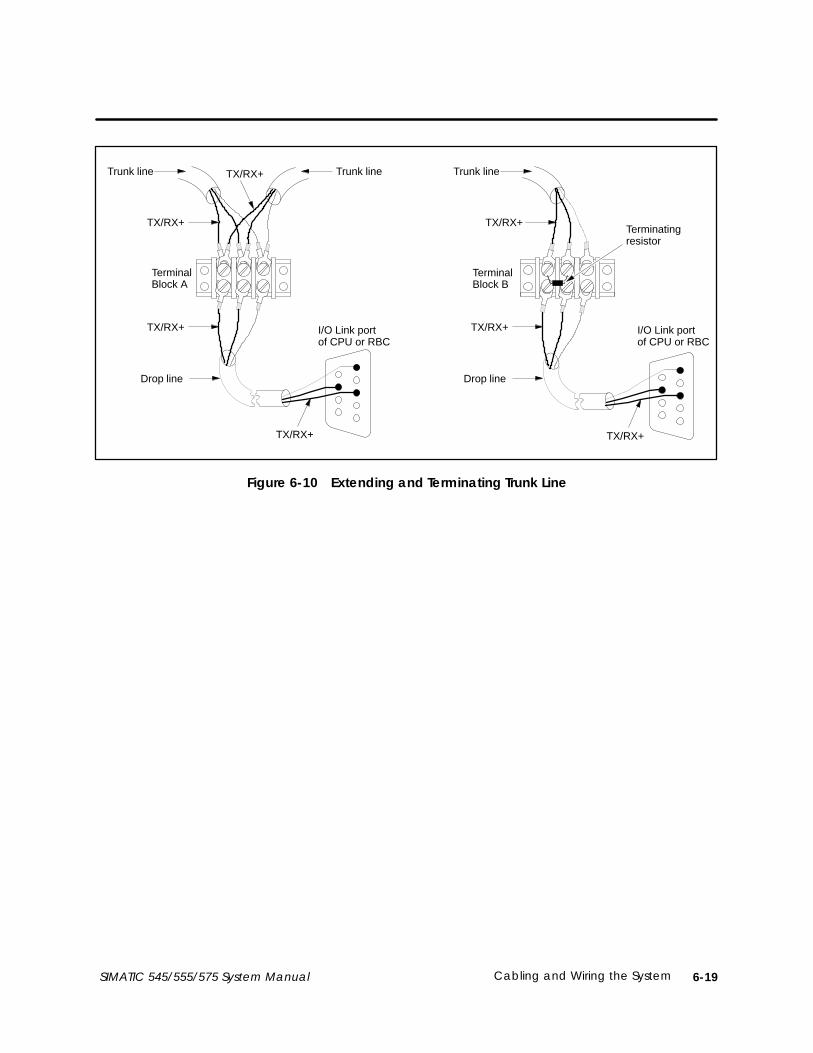
6-19Cabling and Wiring the SystemSIMATIC 545/555/575 System Manual
TerminalBlock A
TerminalBlock B
Drop line
TX/RX+
TX/RX+
TX/RX+
I/O Link portof CPU or RBC
Trunk line
TX/RX+
TX/RX+ TX/RX+
Drop line
I/O Link portof CPU or RBC
TX/RX+
Trunk line Trunk line
Terminatingresistor
Figure 6-10 Extending and Terminating Trunk Line

Cabling and Wiring the System6-20 SIMATIC 545/555/575 System Manual
6.3 Installing PROFIBUS-DP I/O Cables
The PROFIBUS-DP I/O channel provides serial communication over eitherof the following:
• Shielded twisted pair (RS-485) cable media
• Glass or plastic fiber optic media
This section describes the twisted pair RS-485 cable. If you are installing aglass or plastic fiber optic system, follow the instructions in the SINECL2/L2FO Network Components Manual, order number 6GK1970–5CA00–0AA1.
Figure 6-11 shows a simple I/O system layout for the PROFIBUS-DPinterface. On the PROFIBUS-DP I/O channel, the CPU is a master and I/Odevices are slaves.
PROFIBUS-DPfield bus
P/S
P/S
Local I/O
RBC
Local I/O
slave #2
slave #3
slave #112
.
PROFIBUS-DP I/O linkto RBC
Up to 112 PROFIBUS-DPdevices (with repeaters)
CPU
CPU withPROFIBUS-DPI/O interface
PROFIBUS-DPRBC,PPX:505–6870
slave #1
Figure 6-11 Sample System Layout for PROFIBUS-DP
Media Options
System Layout

6-21Cabling and Wiring the SystemSIMATIC 545/555/575 System Manual
Standard PROFIBUS-DP cable, connectors, and repeaters are availablefrom Siemens to cable and wire your installation. The components listed inTable 6-4 are recommended for all installations. They support baud ratesfrom 9.6 kbaud through 12 Mbaud.
Table 6-4 PROFIBUS-DP Components—All Baud Rates
Item Order Number Comment
Cable 6XV1 830–0AH10
Connector 6ES7 972–0BA10–0XA0
Connector 6ES7 972–0BB10–0XA0 Includes PG port
Repeater 6ES7 972–0AA00–0XA0
Table 6-5 lists alternate-choice components, for use only in low baud-rateapplications ranging between 9.6 kbaud and 1.5 Mbaud.
Table 6-5 PROFIBUS-DP Components—Low Baud Rates
Item Order Number Comment
Connector 6ES5 762–2AA12
Connector 6ES5 762–2AA21 Includes PG port
Repeater 6GK1 5100–AC00 24 VDC
Repeater 6GK1 5100–AD00
Equipment Needed

Cabling and Wiring the System6-22 SIMATIC 545/555/575 System Manual
Installing PROFIBUS-DP I/O Cables (continued)
Table 6-6 lists the PROFIBUS DIN 19245 cable line specifications.
Table 6-6 PROFIBUS-DP Cable Specifications
Parameter Value
Impedance 135–165 Ohm (3–20 MHz)
Capacitance 9.1 pF/ft. (<30 nF/km)
Resistance 33.5 /1000 ft. (<110 Ohm/km)
Attenuation 0.27 dB/100 ft. (0.9 dB/100 m (f=200kHz))
Conductor Area 20–22 AWG (0.3 mm2 ... 0.5 mm2)
Cable Diameter 0.315 in. 0.02 in. (8 mm 0.5 mm)
Up to 10 bus segments can be connected in series. The distance between thetwo most widely separated stations must not exceed the appropriate valueshown in Table 6-7. Use repeaters between each cable segment.
Table 6-7 PROFIBUS-DP Line Length Limits
Baud Rate Maximum SegmentLength
Maximum InstallationLength
9.6 to 93.75 kbaud 3,930 ft. (1,200 m) 39,300 ft. (12,000 m)
187.5 kbaud 3,280 ft. (1,000 m) 32,800 ft. (10,000 m)
500 kbaud 1,310 ft. (400 m) 13,100 ft. (4,000 m)
1.5 Mbaud 660 ft. (200 m) 6,600 ft. (2,000 m)
3 to 12 Mbaud 330 ft. (100 m) 3,300 ft. (1,000 m)
PROFIBUS-DP Cableand ConnectorSpecifications
PROFIBUS-DP LineLength Limits

6-23Cabling and Wiring the SystemSIMATIC 545/555/575 System Manual
The rules for proper PROFIBUS-DP installation follow:
• Create a daisy-chain arrangement, not a star arrangement. A daisychain has two connectors with a single cable (bus wire) connection; allother connectors (if any) have two cable (bus wires) connections.
• You can connect up to 32 devices on one cable segment. Repeaters countas devices.
• Do not run the cables near power wires.
• The communication cable consists of two color-coded insulated wiresthat are twisted together and surrounded by a shield. The cable isencased in an insulating jacket. When wiring the system, the samecolor of wire must be connected to the TX/RX+ pin throughout thesystem.
• Do not cross the TX/RX+ signals and the TX/RX– signals. Wire all ofthe TX/RX+ pins (terminal B on the Siemens connectors) together oneach slave device and on the PROFIBUS-DP annex card. Wire all of theTX/RX– pins (terminal A on the Siemens connectors) together to eachslave device and to the PROFIBUS-DP annex card. Crossing the wiresat any point in the system causes communication problems.
• Proper termination and bias of PROFIBUS-DP cable is important forreliable communication. The device at each extreme end of aPROFIBUS-DP cable must be terminated and biased; any connectionsmade between extreme cable ends must not be terminated or biased.See pages 6-24 and following for more information about terminationand bias.
• Ground the chassis of each module to earth ground, as described inChapter 2.
• All PROFIBUS-DP cable connectors must be properly grounded. With aSiemens PROFIBUS-DP connector, proper grounding is accomplishedwhen the bare cable shield contacts the metal connector ground.
• Tighten screws on all PROFIBUS-DP connectors throughout yoursystem to a maximum torque of 8 in–lb (0.9 N–m) in order to ensure agood ground connection.
InstallingPROFIBUS-DP Cable

Cabling and Wiring the System6-24 SIMATIC 545/555/575 System Manual
Installing PROFIBUS-DP I/O Cables (continued)
The device at each extreme end of a PROFIBUS-DP cable must beterminated and biased; any connections made between extreme cable endsmust not be terminated or biased. See the examples below.
If a CPU with PROFIBUS-DP interface is located at an extreme end of thecable, it must be terminated and biased. The device at the other end of thecable must be terminated and biased. See Figure 6-12.
=PROFIBUS-DP Node
Termination and bias required.
Cable end must beterminated and biased.
N
N
N N N
CPU withPROFIBUS-DPI/O interface
Figure 6-12 Terminate CPU at Endpoint
If the CPU with PROFIBUS-DP interface is not at an extreme end of thecable, do not terminate and bias it. Only terminate and bias the devices ateach cable end. See Figure 6-13.
=PROFIBUS-DP Node
Do not terminate and bias.
Cable end must beterminated and biased.
Cable end must beterminated and biased.
N
N CPU withPROFIBUS-DPI/O interface
N N N N N
Figure 6-13 Do Not Terminate at Midpoint
Termination andBias

6-25Cabling and Wiring the SystemSIMATIC 545/555/575 System Manual
Siemens PROFIBUS-DP connectors have selectable termination and biasbuilt in. The connectors designed to handle baud rates from 9600 baud to12 Mbaud (see Table 6-4) have an external switch: see Figure 6-14. The lowbaud-rate connectors (9600 baud to 1.5 Mbaud; Table 6-5) have an internalswitch: see Figure 6-15. In both cases, you set the selection switch to the Onposition to enable termination and bias, or Off to disable termination andbias.
9-pinD-connector
ExternalTerminationSwitch
ON
OFF
Figure 6-14 Preferred Connector, External Termination Switch
Connector InteriorConnector Housing
ON/1 OFF/0
BA BA
ÂÂÂÂ
Internal Termination Switch
Figure 6-15 Low Baud-Rate Connector, Internal Termination Switch
Using a TerminationSelection Switch

Cabling and Wiring the System6-26 SIMATIC 545/555/575 System Manual
Installing PROFIBUS-DP I/O Cables (continued)
Figure 6-16 shows the schematic for PROFIBUS-DP connectors designed tohandle all baud rates, from 9600 baud to 12 Mbaud (as listed in Table 6-4).*
Pin 6(BIAS SUPPLY +5V)
Pin 5(BIAS SUPPLY GND)
Pin 3(TX/RX+)
Pin 8(TX/RX–)
Termination Resistor, 220 ohm, 1/8 W, 5%
Pins 1, 2, 4, 7, and 9 are not connected.
Bias Resistor, 390 ohm, 1/8 W, 5%
Bias Resistor, 390 ohm, 1/8 W, 5%
110 nH
110 nH
110 nH
110 nH
Internal Connection B
Internal Connection B
Internal Connection A
Internal Connection A
Figure 6-16 9600 baud to 12 Mbaud Connector Schematic
PROFIBUS-DPConnectorSchematics

6-27Cabling and Wiring the SystemSIMATIC 545/555/575 System Manual
Figure 6-17 shows the schematic for connectors designed only to handle lowbaud rates, from 9600 baud to 1.5 Mbaud (as listed in Table 6-5).*
Pin 6(BIAS SUPPLY +5V)
Pin 3(TX/RX+)
Pin 8(TX/RX–)
Pin 5(BIAS SUPPLY GND)
Bias Resistor, 390 ohm, 1/8 W, 5%
Termination Resistor, 220 ohm, 1/8 W, 5%
Bias Resistor, 390 ohm, 1/8 W, 5%
Internal Connection BInternal Connection B
Internal Connection AInternal Connection A
Pins 1, 2, 4, 7, and 9 are not connected.
Figure 6-17 9600 baud to 1.5 Mbaud Connector Schematic
PROFIBUS-DP I/O channel connection to some slaves cannot beaccomplished with the standard Siemens connector. Refer to the slavedocumentation for termination and bias options and ensure that everyPROFIBUS-DP device that requires termination and bias meets theschematics shown in Figure 6-16 and Figure 6-17.
) (*( *%&* *%&* + ,* ( *%- .&%( (&*/ %*0 .&%( (* & '- 1 (&(2 */2 & &( +( % 3 &(/

Cabling and Wiring the System6-28 SIMATIC 545/555/575 System Manual
Installing PROFIBUS-DP I/O Cables (continued)
The following procedure describes how to attach a typical connector to yourcable. Also consult the instructions that come with your specific Siemensconnector.
1. Open the connector housing by loosening both housing screws(see Figure 6-18).
9-pinD-connector
Housing screwsCable guide
ExternalTerminationSwitch
ON
OFF
Figure 6-18 Typical PROFIBUS-DP Connector
2. Remove the cover of the housing.
3. Remove 1.25 inches (31 mm) of the cable sheath to expose the shieldingbelow. See Figure 6-19.
Approx. 3/4 in. (19 mm)Approx. 1/2 in. (13 mm)
Cable shieldingApprox. 1/2 in. (12 mm)
Approx. 1/4 in. (6 mm)
Figure 6-19 Stripping the Wires
Installing aPROFIBUS-DPConnector

6-29Cabling and Wiring the SystemSIMATIC 545/555/575 System Manual
4. Remove a 0.75-inch (19 mm) portion of the cable shielding to expose thetwo signal wires.
To ensure that the connection is properly grounded, you must leaveenough exposed cable shielding (0.5 inches, 13 mm) to make a propercontact with the metal cable guide on the connector. See Figure 6-19.
5. Remove 0.25 inches (6 mm) of insulation at the wire ends.
6. Insert the signal wires into the cable terminals.
Be sure to connect the same wire color to the TX/RX+ pin for everydevice throughout your system. Crossing the wires at any point createscommunications problems.
7. Set the termination switch to the correct position. See Figure 6-20.
Switch position ON(termination andbias enabled)
É
É
A B A B
ON
OFF
Switch position OFF(termination andbias disabled)
ÉÉ
ÉÉ
A B A B
ON
OFF
A. Attaching connector at cable end
B. Attaching connector to midpoint of cable
Figure 6-20 Attaching Connector and Selecting Termination

Cabling and Wiring the System6-30 SIMATIC 545/555/575 System Manual
Installing PROFIBUS-DP I/O Cables (continued)
8. Put the cover back on the connector housing.
Be sure that the bare cable shielding makes contact with the metalcable guide on the connector, to ensure proper grounding for theconnection.
9. Tighten the connector housing screws to a maximum torque of 8 in–lb(0.9 N–m) in order to ensure a good connection.

6-31Cabling and Wiring the SystemSIMATIC 545/555/575 System Manual
Figure 6-21 shows the pinout for the PROFIBUS-DP port for the products(e.g., CPUs, RBCs) that are described in this manual.
NOTE: Pins 2 and 7 are “No Connect” for the products described in thismanual. For some PROFIBUS products, these pins are used to provide24 VDC for powering a programming or configuration tool. Such tools arenot powered by the products described in this manual. It is acceptable for anexternally-powered PROFIBUS programming or configuration tool to drivepins 2 and 7 to 24 VDC.
1
2
*3
NO CONNECT
TX/RX+
4
5
6
RTS
7 NO CONNECT
*8 TX/RX–
9
Pin Signal
Female 9-Pin D-Connector
* For Pin 3: Terminal B on Siemens connector.* For Pin 8: Terminal A on Siemens connector.
BIAS SUPPLY GND (5)
TX/RX+ (3)TX/RX– (8)
6 1
95
BIAS SUPPLY GND
CHASSIS GND or NC
BIAS SUPPLY +5V
BIAS SUPPLY GND
(D-shell) CHASSIS GND
Figure 6-21 PROFIBUS-DP I/O Port Pinouts
CAUTIONPin 5 (BIAS SUPPLY GND) and Pin 6 (BIAS SUPPLY +5V) on the PROFIBUS-DPconnector are designed to support the PROFIBUS-DP I/O channel only. Thesepins have a limited output power capability of approximately 0.45 W, whichgreatly exceeds the typical PROFIBUS-DP load; however, overloading thesepins may cause internal component damage.
If the pins are overloaded, the PROFIBUS-DP port can be renderednon-functional, requiring the unit to be returned to the factory for repair.
Do not overload the pins on the PROFIBUS-DP connector.
PROFIBUS-DP PortPinout

Cabling and Wiring the System6-32 SIMATIC 545/555/575 System Manual
6.4 Connecting Modems
545, 555, and 575 CPUs can communicate through Port 1 (RS-232) to anoperator interface or programming station through a dedicated line ordial-up phone modems. Dedicated line operation is a line used exclusively toconnect the modems. Dial-up phone operation connects the modems bytelephone lines. Refer to Figure 6-22 for a typical configuration.
RS-232(9-Pin Port
for545/555)
(25-Pin Portfor
575)
CPU
ProgrammingDevice
Modem Modem
Connect in accordance with the modem manual
545/555 CPUs require 25-9 pin female adapter,INMAC 359–4 (or equivalent)
Cable(2462553–0001)
Cable(2462553–0001)
25-9 pin female adapter,INMAC 359–4 (if needed)
EIA RS-232C connectors
EIA RS-232C connector
Figure 6-22 Modem Configuration
NOTE: The modems must provide an EIA RS-232C DTE interface to thecontroller and operator interface and must have a built-in error correctioncapability. Although the controller supports both full- and half-duplexcommunications, TISOFT only supports full-duplex communications.
Overview
6-33Cabling and Wiring the SystemSIMATIC 545/555/575 System Manual
Use these procedures to establish communication between modems in adedicated line configuration.
1. Connect the modem configuration.
2. Ensure that the CPU and modem baud rates are set to the same value.
NOTE: If the modems are auto-bauding, ensure that the CPU baud rate isset within the baud rate range of the modems.
3. Power up the modems and verify that they are connected, usually byconsulting an indicator on the modems.
4. Start TISOFT; TISOFT auto-bauds to the system’s baud rate (CPU andmodem).
Use these procedures to establish communication between modems in adial-up phone line configuration.
1. Connect the modem configuration.
2. Ensure that the CPU and modem baud rates are set to the same value.
3. Depending on the type of modems being used, the following are threeways to establish communication between the modems.
• Manually call from one modem station to the other modem stationand then switch on both modems.
• Manually call from one modem station to an auto-answer modemat the other station.
• Use TIDIAL dialing software installed with TISOFT Release 5.0 tocall an auto-answer modem at the CPU modem station.
4. Start TISOFT; TISOFT auto-bauds to the system (CPU and modems)baud rate.
Dedicated LineOperation
Dial-up Phone LineOperation
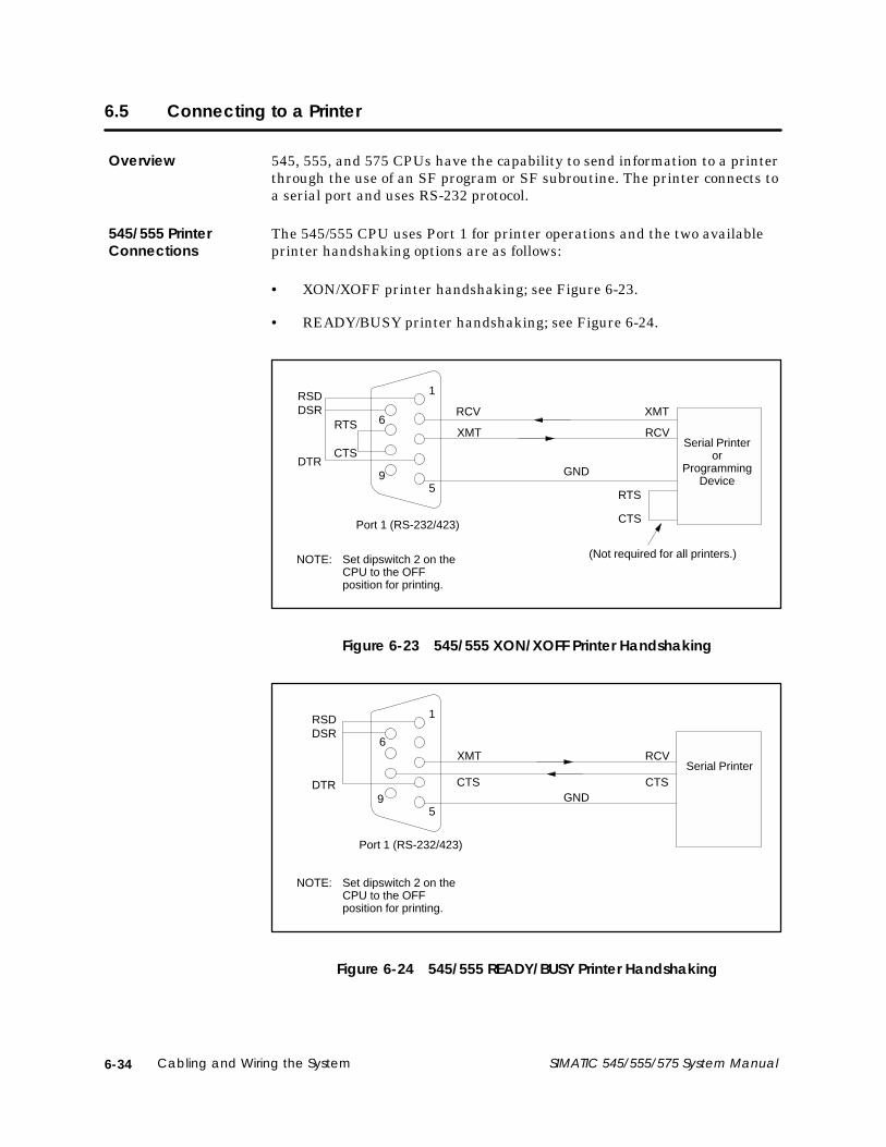
Cabling and Wiring the System6-34 SIMATIC 545/555/575 System Manual
6.5 Connecting to a Printer
545, 555, and 575 CPUs have the capability to send information to a printerthrough the use of an SF program or SF subroutine. The printer connects toa serial port and uses RS-232 protocol.
The 545/555 CPU uses Port 1 for printer operations and the two availableprinter handshaking options are as follows:
• XON/XOFF printer handshaking; see Figure 6-23.
• READY/BUSY printer handshaking; see Figure 6-24.
NOTE: Set dipswitch 2 on theCPU to the OFFposition for printing.
(Not required for all printers.)
RCV XMT
XMT RCV
GND
RTS
CTSPort 1 (RS-232/423)
RTS
CTS
RSDDSR
DTR9
6
5
1
Serial Printeror
ProgrammingDevice
Figure 6-23 545/555 XON/XOFF Printer Handshaking
CTS CTS
XMT RCV
GND
Port 1 (RS-232/423)
RSDDSR
DTR9
6
5
1
Serial Printer
NOTE: Set dipswitch 2 on theCPU to the OFFposition for printing.
Figure 6-24 545/555 READY/BUSY Printer Handshaking
Overview
545/555 PrinterConnections

6-35Cabling and Wiring the SystemSIMATIC 545/555/575 System Manual
The 575 CPU uses Port 2 for printer operations. You can set the baud rate ofthis port using TISOFT. The two available printer handshaking options areas follows:
• XON/XOFF printer handshaking; see Figure 6-25.
• READY/BUSY printer handshaking; see Figure 6-26.
14
2513
1
GND
TD
RD
SerialPrinterDTR
DCD
CTS
RTS
RD
TD
Not requiredfor allprinters.
RTS
CTS
8
7
5
2
20
4
3
25-Pin, MaleD Connector
Port 2 (RS-232)
Figure 6-25 575 XON/XOFF Printer Handshaking
14
2513
1
GND
RTS
RD
SerialPrinterDTR
DCD
CTS
TD
8
7
5
2
20
25-Pin, MaleD Connector
Port 2 (RS-232)
Figure 6-26 575 Ready/Busy Printer Handshaking
575 PrinterConnections

7-1Using EEPROMs for Program StorageSIMATIC 545/555/575 System Manual
Chapter 7
Using EEPROMs for Program Storage
7.1 Program Storage Options 7-2. . . . . . . . . . . . . . . . . . . . . . . . . . . . . . . . . . . . . . . . . . . . . . . . . . . . . . . . Overview 7-2. . . . . . . . . . . . . . . . . . . . . . . . . . . . . . . . . . . . . . . . . . . . . . . . . . . . . . . . . . . . . . . . . . . . . . . On-Board Flash EEPROM Program Storage 7-2. . . . . . . . . . . . . . . . . . . . . . . . . . . . . . . . . . . . . . . Optional Portable (E)EPROM Program Storage 7-2. . . . . . . . . . . . . . . . . . . . . . . . . . . . . . . . . . . EEPROM Portability 7-3. . . . . . . . . . . . . . . . . . . . . . . . . . . . . . . . . . . . . . . . . . . . . . . . . . . . . . . . . . . . . . Using an EEPROM 7-3. . . . . . . . . . . . . . . . . . . . . . . . . . . . . . . . . . . . . . . . . . . . . . . . . . . . . . . . . . . . . . . Using an EPROM 7-3. . . . . . . . . . . . . . . . . . . . . . . . . . . . . . . . . . . . . . . . . . . . . . . . . . . . . . . . . . . . . . . . What is Stored in Non-Volatile Memory 7-4. . . . . . . . . . . . . . . . . . . . . . . . . . . . . . . . . . . . . . . . . . . Program Storage Operations 7-5. . . . . . . . . . . . . . . . . . . . . . . . . . . . . . . . . . . . . . . . . . . . . . . . . . . . Memory and Mode Status at Powerup 7-5. . . . . . . . . . . . . . . . . . . . . . . . . . . . . . . . . . . . . . . . . . .
7.2 Configuring the CPU for Non-Volatile EEPROM Program Storage 7-6. . . . . . . . . . . . . . . . . . . . Configuring the CPU for Portable EEPROM Usage 7-6. . . . . . . . . . . . . . . . . . . . . . . . . . . . . . . . . Configuring the CPU for On-Board EEPROM Usage 7-8. . . . . . . . . . . . . . . . . . . . . . . . . . . . . . . .
7.3 Copying a Program into an EEPROM 7-10. . . . . . . . . . . . . . . . . . . . . . . . . . . . . . . . . . . . . . . . . . . . .
7.4 Editing a Program Stored in an EEPROM 7-12. . . . . . . . . . . . . . . . . . . . . . . . . . . . . . . . . . . . . . . . . .

7-2 Using EEPROMs for Program Storage SIMATIC 545/555/575 System Manual
7.1 Program Storage Options
You can download your program into a non-volatile, read-only memory chipfor additional program security. Program storage options include portableElectrically Erasable Programmable Read-Only Memory (EEPROM) orErasable Programmable Read-Only Memory (UV-erasable EPROM) chipsand permanent on-board EEPROMs.
The CPUs listed in Table 7-1 provide on-board, permanent, non-volatileflash EEPROM memory for program storage. The program memory storagecapacities for each CPU are also listed.
The 575–2105 and 575–2106 CPUs provide only on-board program storage.
Table 7-1 Program Storage Capacities
CPU Model User Memory in RAM On-Board User Memory Capacity
545–1105 96 Kbytes 96 Kbytes
545–1106 192 Kbytes 192 Kbytes
555–1105 384 Kbytes 384 Kbytes
555–1106 1856 Kbytes 1790 Kbytes
575–2105 832 Kbytes 832 Kbytes
575–2106 1856 Kbytes 1790 Kbytes
All 545 and 555 CPUs offer the option of storing your application programin non-volatile form, by means of portable dual in-line pin (DIP) EEPROMor EPROM chips. (The 575 CPUs do not support this option.)
Table 7-2 lists the (E)EPROMS available for use with 545/555 CPUs.
Table 7-2 Program Storage Using (E)EPROM
Storage Type ROM Size Program Size Order Number
EEPROM 128 Kbytes 126 Kbytes 2587681–8022
EEPROM 256 Kbytes 254 Kbytes 2587681–8030
EPROM* 128 Kbytes 126 Kbytes 2587681–8023
EPROM* 256 Kbytes 254 Kbytes 2587681–8031
*The EPROM chips cannot be programmed on the CPU. You must use an EPROM copier tocopy your progam from an EEPROM to the EPROM chip.
Overview
On-Board FlashEEPROM ProgramStorage
Optional Portable(E)EPROM ProgramStorage

7-3Using EEPROMs for Program StorageSIMATIC 545/555/575 System Manual
EEPROMS are portable if, and only if, they meet the following criteria:
• The firmware of the CPU on which the EEPROM was created iscompatible with the firmware of the destination CPU.
EEPROMs created with firmware from Release 1.x through Release 3.xare compatible forward and backward. However, Release 4.0 is notbackward-compatible; you can use EEPROMs created under earlierfirmware on a Release 4.0 CPU, but you cannot take an EEPROMcreated under Release 4.0 and transfer it to a CPU with firmware fromRelease 1.x through Release 3.x.
• The EEPROM program was created on a CPU that had a memoryconfiguration smaller than or equal to the memory available on thedestination CPU.
• If the EEPROM program was created on a CPU that had aPROFIBUS-DP I/O configuration, the destination CPU must have thehardware to support such a configuration.
• If the EEPROM program was created on a CPU that had a Series 505remote I/O configuration, the destination CPU must have the hardwareto support such a configuration (545–1103 CPUs do not support theSeries 505 remote I/O channel).
If you install an EEPROM, the CPU allows you to save your currentprogram without using a separate EEPROM programming device. Theprogram can be downloaded directly from RAM to the EEPROM by usingTISOFT auxiliary function 84 or the corresponding function in SoftShop(select the menu command PLC Utilities → PLC Operations). SeeSection 7.2 for instructions on installing an EEPROM chip. See Section 7.3for instructions on storing a program using an EEPROM.
If your operating program does not change, you can store it permanently onan EPROM. You can use an EPROM copier to copy your program from anEEPROM to an EPROM. (The EPROM cannot be programmed in the CPU.)This is a cost-effective method for creating duplicate copies if you haveadditional CPUs running the same program.
EEPROM Portability
Using an EEPROM
Using an EPROM

7-4 Using EEPROMs for Program Storage SIMATIC 545/555/575 System Manual
Program Storage Options (continued)
The EEPROM stores the following elements of the user program:
• Relay ladder logic (RLL)
• K-memory
• U-memory
• S-memory (PID loops, analog alarms, and SF programs)
• Memory configuration
• I/O configuration
• Password, if installed
• Scan configuration
NOTE: The current values for timer, counter, and drum presets (TCP, DSP,and DCP) are not copied to the EEPROM. You must ensure that your RLLprogram has the preset values that you desire for TCP, DSP, and DCPbefore you save your program to the EEPROM. When your program isrestored from the EEPROM, preset values for TCP, DSP, and DCP arerestored from the program’s RLL instructions.
Values stored in V-memory are not copied to EEPROM. Any operationalconstants that are to be retained following restoration from EEPROM mustbe kept in K-memory or as part of the RLL program. V-memory is initializedto zero when the program is restored from EEPROM.
After storage in the EEPROM, this data is saved even if power is cycledwithout a back-up battery. However, other data in memory (e.g., V-memory)will be lost if you do not have a back-up battery.
NOTE: To help ensure that the data listed above is saved, the total usermemory space to be stored in the EEPROM must not exceed the EEPROMcapacity, depending on EEPROM model (see Table 7-2). If the total usermemory (not system memory) space occupied by these areas is greater thanthe EEPROM capacity, no data is saved. The error message OPERATIONFAILED is displayed on the screen if the user memory exceeds the applicablesize when attempting to save the data.
What is Stored inNon-VolatileMemory

7-5Using EEPROMs for Program StorageSIMATIC 545/555/575 System Manual
You can manage operation of EEPROMs by using SoftShop (select the menucommand PLC Utilities → PLC Operations) or TISOFT AUX 84 on yourprogramming unit. Your programming package allows you to do thefollowing procedures:
• Copy RAM to EEPROM.
• Copy EEPROM to RAM.
• Select RAM as program source.
• Select EEPROM as program source.
• Erase the program in EEPROM.
• Report source (RAM OR EEPROM) of program being executed.
When you power up your system, the CPU checks the status of the(E)EPROM and the battery. A clear (un-programmed) (E)EPROM isequivalent to having no (E)EPROM installed. Table 7-3 lists mode andmemory status (after powerup) that result from various battery and(E)EPROM conditions.
Table 7-3 Mode and Memory Status after Powerup
Conditions Results
BatteryStatus
Programmed (E)EPROMand Program Source =
EEPROM
CPUMemory
CPUMode
Bad or Off No Cleared PROGRAM
Bad or Off YesCleared, then loadedwith program that isin (E)EPROM
RUN
Good and On No No change Mode prior topower loss
Good and On Yes (same program) No change Mode prior topower loss
Good and On Yes (different program)Cleared, then loadedwith program that isin (E)EPROM
RUN
Program StorageOperations
Memory and ModeStatus at Powerup

7-6 Using EEPROMs for Program Storage SIMATIC 545/555/575 System Manual
7.2 Configuring the CPU for Non-Volatile EEPROM Program Storage
Follow the instructions in this section to configure and install an EEPROMin your 545 or 555 CPU. (The 575 CPUs do not support this option.)
NOTE: If you are installing an EEPROM and intend to download a program(from RAM memory), ensure that the back-up battery is enabled and good(BATT GOOD LED is on). Power to the base must be turned off and,without a functioning back-up battery, your program may be lost whenpower is restored. You may want to use TISOFT AUX 60 (SAVE PLC →ALL) or the corresponding function in SoftShop to save your program todisk before proceeding.
1. Place the CPU in PROGRAM Mode.
2. Ensure that switch 9 on the CPU dipswitch is turned On (to the left).This enables the back-up battery.
3. Turn off all user-supplied power to the 545/555 base.
CAUTIONThe CPU is sensitive to, and can be damaged by, electrostatic discharge.
Personnel must make contact with a static-dissipative pad and/or wear agrounded wrist strap when handling the CPU.
4. Remove the CPU from the base assembly and place the CPUcomponent-side-up on a static-dissipative surface.
5. Insert the (E)EPROM into the socket on the CPU, aligning the notcheson the (E)EPROM and the socket (see Figure 7-1 or Figure 7-2,depending on your CPU model).
6. Check the pins to make sure that they are all seated properly in thesocket.
7. Observe Jumper E18. If you intend to write to the EEPROM, ensurethat Jumper E18 is strapped. If you do not write to the EEPROM andwant to disable this feature, remove strap E18.
For the new CPU models (–1105, –1106), set the jumper on header E20to strap the pins marked “DIP EEPROM” as shown in Figure 7-2.
8. Re-install the CPU in the base and turn the base power On. Refer toChapter 9 of this manual if the (E)EPROM fails to function correctly.
To copy a program into the EEPROM, see Section 7.3.
Configuring theCPU for PortableEEPROM Usage

7-7Using EEPROMs for Program StorageSIMATIC 545/555/575 System Manual
Note location of notches
Figure 7-1 (E)EPROM Socket and Jumper Pins for –1103/–1104 CPUs
Note locationof notches
E16
E20
E18
Figure 7-2 (E)EPROM Socket and Jumper Pins for –1105/–1106 CPUs

7-8 Using EEPROMs for Program Storage SIMATIC 545/555/575 System Manual
Configuring the CPU for Non-Volatile EEPROM Program Storage (continued)
The 575 CPUs require no configuration to store programs in non-volatilememory. The 545/555–1105 and –1106 CPU models are configured at thefactory to enable the permanent on-board EEPROM as the default programstorage option. If you have not changed the board configuration, skip thisprocedure, and refer to Section 7.3 to copy a program into the on-board flashEEPROM.
If you have changed the board configuration at any time, follow theseinstructions to configure the CPU for on-board EEPROM program storage.
NOTE: Ensure that the back-up battery is enabled and good (BATT GOODLED is on). Power to the base must be turned off and, without a functioningback-up battery, your program may be lost when power is restored. You maywant to use TISOFT AUX 60 (SAVE PLC → ALL) or the correspondingfunction in SoftShop to save your program to disk before proceeding.
1. Place the CPU in PROGRAM Mode.
2. Ensure that switch 9 on the CPU dipswitch is turned On (to the left).This enables the back-up battery.
3. Turn off all user-supplied power to the 545/555 base.
CAUTIONThe CPU is sensitive to, and can be damaged by, electrostatic discharge.
Personnel must make contact with a static-dissipative pad and/or wear agrounded wrist strap when handling the CPU.
4. Remove the CPU from the base assembly and place the CPUcomponent-side-up on a static-dissipative surface.
5. If a portable EEPROM is installed in the socket on the CPU, you mustremove it in order to select on-board EEPROM program storage.
6. Set the jumper on header E20 to strap the pins marked “ON BRDFLASH” (on-board flash memory) as shown in Figure 7-3.
7. Re-install the CPU in the base and turn the base power On. Refer toChapter 9 of this manual if the (E)EPROM fails to function correctly.
To copy a program into the on-board flash EEPROM, see Section 7.3.
Configuring theCPU for On-BoardEEPROM Usage

7-9Using EEPROMs for Program StorageSIMATIC 545/555/575 System Manual
E16
E20
E18
Figure 7-3 Jumper Pin Settings for On-Board Memory Program Storage

7-10 Using EEPROMs for Program Storage SIMATIC 545/555/575 System Manual
7.3 Copying a Program into an EEPROM
Ensure that you have configured the CPU to select the desired EEPROM,portable or on-board (refer to Section 7.2), and then continue with the stepslisted below.
1. Enter the program into the CPU. Verify that your program is correct,and save your program to your programming unit hard disk.
2. Set the CPU to PROGRAM mode.
3. Select the TISOFT auxiliary function AUX 84 (or select the menucommand PLC Utilities → PLC Operations in SoftShop).
4. Use the Source Toggle option to select RAM as your program source.
5. Make any desired changes to the source program which is located inRAM.
6. Use the Erase option to erase program data on the EEPROM.
7. Use the Copy option to copy the program from RAM to the EEPROM.
NOTE: The CPU does not allow changes to program memory during theprogramming of the EEPROM.
8. Use the Source Toggle option to select either RAM or EEPROM as theprogram source. (Refer to Table 7-3 for mode and memory status afterpowerup, based on the battery status and program source selected.)
9. If you selected EEPROM as the program source, use TISOFT AUX 17to check the program carefully while the CPU is in PROGRAM modebefore allowing the CPU to control equipment connected to the I/O.
! WARNINGTo minimize risk of potential injury to personnel or damage to equipment, checkthe program before permitting a CPU to execute from an EEPROM program.
An incorrect program may cause unexpected operation of the process whichcan cause death or serious injury to personnel, and/or damage to equipment.
You must be absolutely certain that the EEPROM program is correct. Takestandard precautions associated with program development and debug.

7-11Using EEPROMs for Program StorageSIMATIC 545/555/575 System Manual
If an error occurs during the copy process it will be listed on theprogramming unit. If an error occurs, perform the following checks:
• Ensure that the EEPROM jumper pin programming enable strap isinstalled correctly (on the 545 or 555 CPUs).
• Ensure that an EEPROM, not an EPROM, is installed (on the 545 or555 CPUs).
• Ensure that all EEPROM pins are properly seated in the socket.
• For CPUs that support both portable and on-board EEPROM, ensurethat the jumper E20 is configured to select your target EEPROM. Inaddition, if you select on-board EEPROM for program storage, ensurethat the portable EEPROM is not installed.
Other possible causes for errors include the following:
• The EEPROM may be defective.
• The EEPROM may already have been programmed (and not erased).Use the TISOFT auxiliary function AUX 84 to erase program data onthe EEPROM.
• The size of your user program that is being stored may exceed the sizeof the installed EEPROM.
If you suspect a defective portable EEPROM, power down, remove theEEPROM, install another EEPROM, power up again and repeat theprogramming procedure.
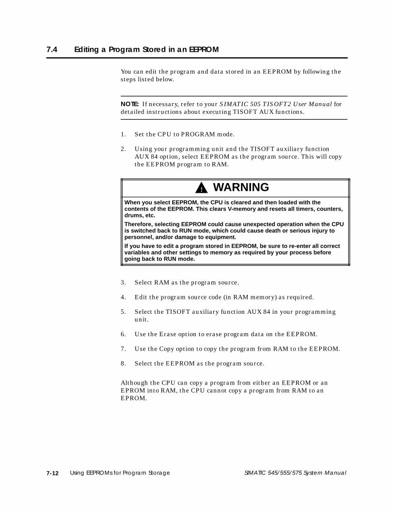
7-12 Using EEPROMs for Program Storage SIMATIC 545/555/575 System Manual
7.4 Editing a Program Stored in an EEPROM
You can edit the program and data stored in an EEPROM by following thesteps listed below.
NOTE: If necessary, refer to your SIMATIC 505 TISOFT2 User Manual fordetailed instructions about executing TISOFT AUX functions.
1. Set the CPU to PROGRAM mode.
2. Using your programming unit and the TISOFT auxiliary functionAUX 84 option, select EEPROM as the program source. This will copythe EEPROM program to RAM.
! WARNINGWhen you select EEPROM, the CPU is cleared and then loaded with thecontents of the EEPROM. This clears V-memory and resets all timers, counters,drums, etc.
Therefore, selecting EEPROM could cause unexpected operation when the CPUis switched back to RUN mode, which could cause death or serious injury topersonnel, and/or damage to equipment.
If you have to edit a program stored in EEPROM, be sure to re-enter all correctvariables and other settings to memory as required by your process beforegoing back to RUN mode.
3. Select RAM as the program source.
4. Edit the program source code (in RAM memory) as required.
5. Select the TISOFT auxiliary function AUX 84 in your programmingunit.
6. Use the Erase option to erase program data on the EEPROM.
7. Use the Copy option to copy the program from RAM to the EEPROM.
8. Select the EEPROM as the program source.
Although the CPU can copy a program from either an EEPROM or anEPROM into RAM, the CPU cannot copy a program from RAM to anEPROM.

Starting Up the System 8-1SIMATIC 545/555/575 System Manual
Chapter 8
Starting Up the System
8.1 Powering Up the System 8-2. . . . . . . . . . . . . . . . . . . . . . . . . . . . . . . . . . . . . . . . . . . . . . . . . . . . . . . . . Overview 8-2. . . . . . . . . . . . . . . . . . . . . . . . . . . . . . . . . . . . . . . . . . . . . . . . . . . . . . . . . . . . . . . . . . . . . . . Start-up Procedures 8-2. . . . . . . . . . . . . . . . . . . . . . . . . . . . . . . . . . . . . . . . . . . . . . . . . . . . . . . . . . . . .
8.2 CPU Memory Configuration 8-4. . . . . . . . . . . . . . . . . . . . . . . . . . . . . . . . . . . . . . . . . . . . . . . . . . . . . . Memory Configuration 8-4. . . . . . . . . . . . . . . . . . . . . . . . . . . . . . . . . . . . . . . . . . . . . . . . . . . . . . . . . . Maximum Configurable Memory 8-4. . . . . . . . . . . . . . . . . . . . . . . . . . . . . . . . . . . . . . . . . . . . . . . .

Starting Up the System8-2 SIMATIC 545/555/575 System Manual
8.1 Powering Up the System
This section provides general guidelines for powering up your system.
! WARNINGYou must be fully informed about safety procedures before you power up thesystem.
Failure to follow safety guidelines could result in death or serious injury topersonnel, and/or damage to equipment.
Review and comply with the safety procedures listed in Chapter 2 beforecompleting the following steps.
Follow these procedures when powering up your system for the first time.
1. Verify the following items.
• Check input power to verify that it matches the voltage used bythe power supply. If necessary, adjust the voltage selector on thepower supply to correspond to input power.
• Check for correct switch settings on all configurable modules,namely, the CPU and annex card(s), if any, and any RBC(s). If youintend to copy user programs into an installed EEPROM, thejumper strap (E18) on your 545/555 CPU must be strapped, andthe CPU must be configured for EEPROM storage (see Chapter 7).
NOTE: Do not install a programmed EEPROM when commissioning yoursystem; the EEPROM must not be programmed before you have verifiedcomponent functionality and system installation and design.
• If any of your system bases have empty I/O slots, use filler bezelsand bezel screws to cover the openings in the base. This preventsdebris from getting into the system; it also helps preventelectrostatic discharge and other types of electrical noiseinterference.
• Ensure that all I/O interface cables are properly connected to I/Ointerface connectors.
• Ensure that all configured bases are properly connected, that thereare no crimps or breaks in the cable, and that base addresses arecorrect.
• Ensure that connector pins are not bent, that all modules aresecurely plugged into the base(s), and that bezel screws aretightened.
Overview
Start-upProcedures

Starting Up the System 8-3SIMATIC 545/555/575 System Manual
2. Initialize the CPU by completing the following procedures:
• If you have not already done so, disable the CPU battery. (For545/555 CPUs, turn off switch 9 on the CPU front dipswitch. For575 CPUs, disconnect the battery.)
• Turn on power to the base.
• With the battery disabled and an unprogrammed (E)EPROM, theCPU clears memory and enters PROGRAM mode.
• Enable the battery backup circuit by turning on switch 9. Thebattery LED should light. The CPU is now initialized.
NOTE: If the battery LED does not come on, the battery is low. The LEDshould be lit when the system is powered and a good battery is installed andenabled.
3. Connect your programming device to one of the CPU communicationports. Place the CPU in PROGRAM mode.
4. Using your programming device, enter the memory and I/Oconfiguration. Refer to Table 8-1, Table 8-2, Table 8-3, Table 8-4, orTable 8-7, as appropriate.
5. Enter the user program. See the SIMATIC 545/555/575 ProgrammingReference User Manual for programming information.
6. Use your programming device to JOG motors, solenoids, or otherpositioning devices one at a time to establish correct rotation orpositioning.
After all the steps are performed and verified, place the CPU in RUN mode.

Starting Up the System8-4 SIMATIC 545/555/575 System Manual
8.2 CPU Memory Configuration
The CPU user memory is user configurable. The actual ranges of memorytypes depend upon how the memory has been configured. Ranges formemory types are listed by CPU model in Table 8-1 through Table 8-7.
You can increase the memory allocated to a particular memory type, a blockat a time, up to the maximum listed. Block sizes vary with the memory type.Refer to the table for your CPU.
For example, when you increase L-memory by one block, from 16 Kbytes to17 Kbytes, system memory reserved for L-memory increases from 48 Kbytesto 51 Kbytes.
The size of configurable system memory is determined by the CPU model.You cannot configure all memory types to their maximum allocation sizesimultaneously. For example, on a 545–1103, if L-memory is configured to30 Kbytes, then S-memory cannot be configured to 32 Kbytes, because the96 Kbytes of system memory would be exceeded.
Refer to your SIMATIC 505 TISOFT2 User Manual and SIMATIC545/555/575 Programming Reference User Manual for additionalinformation on memory configuration and configuring I/O.
Table 8-1 545–1103/–1105 CPU Memory Configuration
Memory TypeBlock
AllocationSize
MemoryRequiredper Block
MinimumSize
MaximumSize
Total MemoryRequired for
Maximum Size
DefaultAllocation
Total memory — — — 96 Kbytes — —
Ladder (L) 1 Kbyte 3 Kbytes 1 Kbyte 30 Kbytes 90 Kbytes 30 Kbytes
Variable (V) 1 Kbyte 1 Kbyte 1 Kbyte 32 Kbytes 32 Kbytes 1 Kbyte
Constant (K) 1 Kbyte 1 Kbyte 0 Kbytes 32 Kbytes 32 Kbytes 0 Kbytes
Special (S) 1 Kbyte 1 Kbyte 0 Kbytes 32 Kbytes 32 Kbytes 0 Kbytes
User (U) 1 Kbyte 1 Kbyte 0 Kbytes 32 Kbytes 32 Kbytes 0 Kbytes
Timer 2* 10 bytes 10 1024 5120 bytes 10
Drum 2* 96 bytes 2 20 960 bytes 2
Shift Register 2* 2 bytes 10 1024 1024 bytes 10
Table Move 1* 2 bytes 10 512 1024 bytes 10
One Shot 2* 2 bytes 10 512 512 bytes 10*Number per block.
MemoryConfiguration
MaximumConfigurableMemory

Starting Up the System 8-5SIMATIC 545/555/575 System Manual
Table 8-2 545–1104/–1106 CPU Memory Configuration
Memory TypeBlock
AllocationSize
MemoryRequiredper Block
MinimumSize
MaximumSize
Total MemoryRequired for
Maximum Size
DefaultAllocation
Total memory — — — 192 Kbytes — —
Ladder (L) 1 Kbyte 3 Kbytes 1 Kbyte 59 Kbytes 177 Kbytes 32 Kbytes
Variable (V) 1 Kbyte 1 Kbyte 1 Kbyte 177 Kbytes 177 Kbytes 52 Kbytes
Constant (K) 1 Kbyte 1 Kbyte 0 Kbytes 176 Kbytes 176 Kbytes 0 Kbytes
Special (S) 1 Kbyte 1 Kbyte 0 Kbytes 176 Kbytes 176 Kbytes 32 Kbytes
User (U) 1 Kbyte 1 Kbyte 0 Kbytes 176 Kbytes 176 Kbytes 0 Kbytes
Timer 1024* 5 Kbytes 1024 20480 100 Kbytes 1024
Drum 64* 3 Kbytes 64 2304 108 Kbytes 64
Shift Register 1024* 1 Kbyte 1024 16384 16 Kbytes 1024
Table Move 1024* 2 Kbytes 1024 14336 28 Kbytes 1024
One Shot 1024* 1 Kbyte 1024 32768 32 Kbytes 1024*Number per block.
Table 8-3 555–1103 CPU Memory Configuration
Memory TypeBlock
AllocationSize
MemoryRequiredper Block
MinimumSize
MaximumSize
Total MemoryRequired for
Maximum Size
DefaultAllocation
Total memory — — — 384 Kbytes — —
Ladder (L) 1 Kbyte 3 Kbytes 1 Kbyte 123 Kbytes 369 Kbytes 32 Kbytes
Variable (V) 1 Kbyte 1 Kbyte 1 Kbyte 369 Kbytes 369 Kbytes 52 Kbytes
Constant (K) 1 Kbyte 1 Kbyte 0 Kbytes 368 Kbytes 368 Kbytes 0 Kbytes
Special (S) 1 Kbyte 1 Kbyte 0 Kbytes 368 Kbytes 368 Kbytes 32 Kbytes
User (U) 1 Kbyte 1 Kbyte 0 Kbytes 368 Kbytes 368 Kbytes 0 Kbytes
Timer 1024* 5 Kbytes 1024 20480 100 Kbytes 1024
Drum 64* 3 Kbytes 64 2304 108 Kbytes 64
Shift Register 1024* 1 Kbyte 1024 16384 16 Kbytes 1024
Table Move 1024* 2 Kbytes 1024 14336 28 Kbytes 1024
One Shot 1024* 1 Kbyte 1024 32768 32 Kbytes 1024*Number per block.

Starting Up the System8-6 SIMATIC 545/555/575 System Manual
CPU Memory Configuration (continued)
Table 8-4 555–1104 CPU Memory Configuration
Memory TypeBlock
AllocationSize
MemoryRequiredper Block
MinimumSize
MaximumSize
Total MemoryRequired for
Maximum Size
DefaultAllocation
Total memory — — — 1920 Kbytes — —
Ladder (L) 1 Kbyte 3 Kbytes 1 Kbyte 635 Kbytes 1905 Kbytes 32 Kbytes
Variable (V) 1 Kbyte 1 Kbyte 1 Kbyte 1905 Kbytes 1905 Kbytes 52 Kbytes
Constant (K) 1 Kbyte 1 Kbyte 0 Kbytes 1904 Kbytes 1904 Kbytes 0 Kbytes
Special (S) 1 Kbyte 1 Kbyte 0 Kbytes 1904 Kbytes 1904 Kbytes 32 Kbytes
User (U) 1 Kbyte 1 Kbyte 0 Kbytes 1904 Kbytes 1904 Kbytes 0 Kbytes
Timer 1024* 5 Kbytes 1024 20480 100 Kbytes 1024
Drum 64* 3 Kbytes 64 2304 108 Kbytes 64
Shift Register 1024* 1 Kbyte 1024 16384 16 Kbytes 1024
Table Move 1024* 2 Kbytes 1024 14336 28 Kbytes 1024
One Shot 1024* 1 Kbyte 1024 32768 32 Kbytes 1024*Number per block.
Table 8-5 555–1105 CPU Memory Configuration
Memory TypeBlock
AllocationSize
MemoryRequiredper Block
MinimumSize
MaximumSize
Total MemoryRequired for
Maximum Size
DefaultAllocation
Total memory — — — 384 Kbytes — —
Ladder (L) 1 Kbyte 3 Kbytes 1 Kbyte 123 Kbytes 369 Kbytes 32 Kbytes
Variable (V) 1 Kbyte 1 Kbyte 1 Kbyte 369 Kbytes 369 Kbytes 52 Kbytes
Constant (K) 1 Kbyte 1 Kbyte 0 Kbytes 368 Kbytes 368 Kbytes 0 Kbytes
Special (S) 1 Kbyte 1 Kbyte 0 Kbytes 368 Kbytes 368 Kbytes 32 Kbytes
CompiledSpecial (CS)
1 Kbyte 1 Kbyte 0 Kbytes 368 Kbytes 368 Kbytes 0 Kbytes
User (U) 1 Kbyte 1 Kbyte 0 Kbytes 368 Kbytes 368 Kbytes 0 Kbytes
Timer 1024* 5 Kbytes 1024 20480 100 Kbytes 1024
Drum 64* 3 Kbytes 64 2304 108 Kbytes 64
Shift Register 1024* 1 Kbyte 1024 16384 16 Kbytes 1024
Table Move 1024* 2 Kbytes 1024 14336 28 Kbytes 1024
One Shot 1024* 1 Kbyte 1024 32768 32 Kbytes 1024*Number per block.

Starting Up the System 8-7SIMATIC 545/555/575 System Manual
Table 8-6 555–1106 CPU Memory Configuration
Memory TypeBlock
AllocationSize
MemoryRequiredper Block
MinimumSize
MaximumSize
Total MemoryRequired for
Maximum Size
DefaultAllocation
Total memory — — — 1856 Kbytes — —
Ladder (L) 1 Kbyte 3 Kbytes 1 Kbyte 614 Kbytes 1842 Kbytes 32 Kbytes
Variable (V) 1 Kbyte 1 Kbyte 1 Kbyte 1841 Kbytes 1841 Kbytes 52 Kbytes
Constant (K) 1 Kbyte 1 Kbyte 0 Kbytes 1840 Kbytes 1840 Kbytes 0 Kbytes
Special (S) 1 Kbyte 1 Kbyte 0 Kbytes 1840 Kbytes 1840 Kbytes 32 Kbytes
CompiledSpecial (CS)
1 Kbyte 1 Kbyte 0 Kbytes 1840 Kbytes 1840 Kbytes 0 Kbytes
User (U) 1 Kbyte 1 Kbyte 0 Kbytes 1840 Kbytes 1840 Kbytes 0 Kbytes
Timer 1024* 5 Kbytes 1024 20480 100 Kbytes 1024
Drum 64* 3 Kbytes 64 2304 108 Kbytes 64
Shift Register 1024* 1 Kbyte 1024 16384 16 Kbytes 1024
Table Move 1024* 2 Kbytes 1024 14336 28 Kbytes 1024
One Shot 1024* 1 Kbyte 1024 32768 32 Kbytes 1024*Number per block.
Table 8-7 575–2104 CPU Memory Configuration
Memory TypeBlock
AllocationSize
MemoryRequiredper Block
MinimumSize
MaximumSize
Total MemoryRequired for
Maximum Size
DefaultAllocation
Total memory — — — 832 Kbytes — —
Ladder (L) 1 Kbyte 3 Kbytes 1 Kbyte 273 Kbytes 819 Kbytes 64 Kbytes
Variable (V) 1 Kbyte 1 Kbyte 1 Kbyte 817 Kbytes 817 Kbytes 52 Kbytes
Constant (K) 1 Kbyte 1 Kbyte 0 Kbytes 816 Kbytes 816 Kbytes 0 Kbytes
Special (S) 1 Kbyte 1 Kbyte 0 Kbytes 816 Kbytes 816 Kbytes 32 Kbytes
User (U) 1 Kbyte 1 Kbyte 0 Kbytes 816 Kbytes 816 Kbytes 0 Kbytes
Timer 1024* 5 Kbytes 1024 20480 100 Kbytes 1024
Drum 64* 3 Kbytes 64 2304 108 Kbytes 64
Shift register 1024* 1 Kbyte 1024 16384 16 Kbytes 1024
Table move 1024* 2 Kbytes 1024 14336 28 Kbytes 1024
One shot 1024* 1 Kbyte 1024 32768 32 Kbytes 1024*Number per block.

Starting Up the System8-8 SIMATIC 545/555/575 System Manual
CPU Memory Configuration (continued)
Table 8-8 575–2105 CPU Memory Configuration
Memory TypeBlock
AllocationSize
MemoryRequiredper Block
MinimumSize
MaximumSize
Total MemoryRequired for
Maximum Size
DefaultAllocation
Total memory — — — 832 Kbytes — —
Ladder (L) 1 Kbyte 3 Kbytes 1 Kbyte 273 Kbytes 819 Kbytes 64 Kbytes
Variable (V) 1 Kbyte 1 Kbyte 1 Kbyte 817 Kbytes 817 Kbytes 52 Kbytes
Constant (K) 1 Kbyte 1 Kbyte 0 Kbytes 816 Kbytes 816 Kbytes 0 Kbytes
Special (S) 1 Kbyte 1 Kbyte 0 Kbytes 816 Kbytes 816 Kbytes 32 Kbytes
CompiledSpecial (CS)
1 Kbyte 1 Kbyte 0 Kbytes 816 Kbytes 816 Kbytes 0 Kbytes
User (U) 1 Kbyte 1 Kbyte 0 Kbytes 816 Kbytes 816 Kbytes 0 Kbytes
Timer 1024* 5 Kbytes 1024 20480 100 Kbytes 1024
Drum 64* 3 Kbytes 64 2304 108 Kbytes 64
Shift Register 1024* 1 Kbyte 1024 16384 16 Kbytes 1024
Table Move 1024* 2 Kbytes 1024 14336 28 Kbytes 1024
One Shot 1024* 1 Kbyte 1024 32768 32 Kbytes 1024*Number per block.
Table 8-9 575–2106 CPU Memory Configuration
Memory TypeBlock
AllocationSize
MemoryRequiredper Block
MinimumSize
MaximumSize
Total MemoryRequired for
Maximum Size
DefaultAllocation
Total memory — — — 1856 Kbytes — —
Ladder (L) 1 Kbyte 3 Kbytes 1 Kbyte 614 Kbytes 1842 Kbytes 64 Kbytes
Variable (V) 1 Kbyte 1 Kbyte 1 Kbyte 1841 Kbytes 1841 Kbytes 52 Kbytes
Constant (K) 1 Kbyte 1 Kbyte 0 Kbytes 1840 Kbytes 1840 Kbytes 0 Kbytes
Special (S) 1 Kbyte 1 Kbyte 0 Kbytes 1840 Kbytes 1840 Kbytes 32 Kbytes
CompiledSpecial (CS)
1 Kbyte 1 Kbyte 0 Kbytes 1840 Kbytes 1840 Kbytes 0 Kbytes
User (U) 1 Kbyte 1 Kbyte 0 Kbytes 1840 Kbytes 1840 Kbytes 0 Kbytes
Timer 1024* 5 Kbytes 1024 20480 100 Kbytes 1024
Drum 64* 3 Kbytes 64 2304 108 Kbytes 64
Shift Register 1024* 1 Kbyte 1024 16384 16 Kbytes 1024
Table Move 1024* 2 Kbytes 1024 14336 28 Kbytes 1024
One Shot 1024* 1 Kbyte 1024 32768 32 Kbytes 1024*Number per block.

Troubleshooting 9-1SIMATIC 545/555/575 System Manual
Chapter 9
Troubleshooting
9.1 Troubleshooting by Using Auxiliary Functions 9-2. . . . . . . . . . . . . . . . . . . . . . . . . . . . . . . . . . . . . Overview 9-2. . . . . . . . . . . . . . . . . . . . . . . . . . . . . . . . . . . . . . . . . . . . . . . . . . . . . . . . . . . . . . . . . . . . . . . Power-up Restart, Partial Restart, and Complete Restart 9-2. . . . . . . . . . . . . . . . . . . . . . . . . . 575 Fault Restarts 9-2. . . . . . . . . . . . . . . . . . . . . . . . . . . . . . . . . . . . . . . . . . . . . . . . . . . . . . . . . . . . . . . Compare PLC to Disk 9-4. . . . . . . . . . . . . . . . . . . . . . . . . . . . . . . . . . . . . . . . . . . . . . . . . . . . . . . . . . . Run 545/555 PLC Diagnostics 9-4. . . . . . . . . . . . . . . . . . . . . . . . . . . . . . . . . . . . . . . . . . . . . . . . . . . . Display Failed I/O 9-4. . . . . . . . . . . . . . . . . . . . . . . . . . . . . . . . . . . . . . . . . . . . . . . . . . . . . . . . . . . . . . . PLC Operational Status 9-4. . . . . . . . . . . . . . . . . . . . . . . . . . . . . . . . . . . . . . . . . . . . . . . . . . . . . . . . .
9.2 Troubleshooting by Reading LEDs 9-6. . . . . . . . . . . . . . . . . . . . . . . . . . . . . . . . . . . . . . . . . . . . . . . . 545/555 LEDs 9-6. . . . . . . . . . . . . . . . . . . . . . . . . . . . . . . . . . . . . . . . . . . . . . . . . . . . . . . . . . . . . . . . . . . 575 LEDs 9-7. . . . . . . . . . . . . . . . . . . . . . . . . . . . . . . . . . . . . . . . . . . . . . . . . . . . . . . . . . . . . . . . . . . . . . . .
9.3 Troubleshooting CPU Fatal Errors 9-8. . . . . . . . . . . . . . . . . . . . . . . . . . . . . . . . . . . . . . . . . . . . . . . . . 545/555 CPU Fatal Error Indications 9-8. . . . . . . . . . . . . . . . . . . . . . . . . . . . . . . . . . . . . . . . . . . . . . 575 CPU Fatal Error Indications 9-8. . . . . . . . . . . . . . . . . . . . . . . . . . . . . . . . . . . . . . . . . . . . . . . . . . . Causes of CPU Fatal Errors 9-9. . . . . . . . . . . . . . . . . . . . . . . . . . . . . . . . . . . . . . . . . . . . . . . . . . . . . . . 545/555 Fatal Errors 9-9. . . . . . . . . . . . . . . . . . . . . . . . . . . . . . . . . . . . . . . . . . . . . . . . . . . . . . . . . . . . . 575 Fatal Errors 9-10. . . . . . . . . . . . . . . . . . . . . . . . . . . . . . . . . . . . . . . . . . . . . . . . . . . . . . . . . . . . . . . . . . 545/555/575 CPU Fatal Error Codes 9-10. . . . . . . . . . . . . . . . . . . . . . . . . . . . . . . . . . . . . . . . . . . . . . 545/555 CPU Responses to Fatal Errors 9-13. . . . . . . . . . . . . . . . . . . . . . . . . . . . . . . . . . . . . . . . . . . . Steps to Clear 545/555 Fatal Errors 9-13. . . . . . . . . . . . . . . . . . . . . . . . . . . . . . . . . . . . . . . . . . . . . . . 575 CPU Responses to Fatal Errors 9-14. . . . . . . . . . . . . . . . . . . . . . . . . . . . . . . . . . . . . . . . . . . . . . . . Steps to Clear 575 Fatal Errors 9-15. . . . . . . . . . . . . . . . . . . . . . . . . . . . . . . . . . . . . . . . . . . . . . . . . . . . Calling for Assistance 9-15. . . . . . . . . . . . . . . . . . . . . . . . . . . . . . . . . . . . . . . . . . . . . . . . . . . . . . . . . . .
9.4 Troubleshooting CPU Non-Fatal Errors 9-16. . . . . . . . . . . . . . . . . . . . . . . . . . . . . . . . . . . . . . . . . . . .
9.5 Troubleshooting by Using Status Words 9-17. . . . . . . . . . . . . . . . . . . . . . . . . . . . . . . . . . . . . . . . . . .
9.6 Troubleshooting User EEPROMs or EPROMs 9-18. . . . . . . . . . . . . . . . . . . . . . . . . . . . . . . . . . . . . . . .
9.7 Troubleshooting Power Supplies 9-19. . . . . . . . . . . . . . . . . . . . . . . . . . . . . . . . . . . . . . . . . . . . . . . . . .
9.8 Checking RS-485 (Twisted Pair) Cable Installation 9-21. . . . . . . . . . . . . . . . . . . . . . . . . . . . . . . . . Using Digital or Analog Meter 9-21. . . . . . . . . . . . . . . . . . . . . . . . . . . . . . . . . . . . . . . . . . . . . . . . . . . . Resistance below Minimum 9-21. . . . . . . . . . . . . . . . . . . . . . . . . . . . . . . . . . . . . . . . . . . . . . . . . . . . . . Resistance above Maximum 9-22. . . . . . . . . . . . . . . . . . . . . . . . . . . . . . . . . . . . . . . . . . . . . . . . . . . .
9.9 Checking PROFIBUS-DP Cable Installation 9-23. . . . . . . . . . . . . . . . . . . . . . . . . . . . . . . . . . . . . . . .
9.10 PROFIBUS-DP Communications Watchdog Timer 9-24. . . . . . . . . . . . . . . . . . . . . . . . . . . . . . . . . .
9.11 Troubleshooting 575 Improper Login 9-25. . . . . . . . . . . . . . . . . . . . . . . . . . . . . . . . . . . . . . . . . . . . . .

Troubleshooting9-2 SIMATIC 545/555/575 System Manual
9.1 Troubleshooting by Using Auxiliary Functions
The troubleshooting information in this chapter is generic unless a specificCPU is stipulated.
The CPUs have self-checking and diagnostic capabilities that can be usedfor troubleshooting. The diagnostics and self-checks are accessible throughthe Auxiliary Function menu on your TISOFT programming device.
When you display the Auxiliary Function menu, the following functions areavailable for resetting the CPU, initiating diagnostics, or displayingdiagnostic information:
• Power-up Restart — AUX 10
• Partial Restart — AUX 11
• Complete Restart — AUX 12
• Compare PLC to Disk — AUX 17
• PLC Diagnostics — AUX 20 (545/555 CPUs only)
• Display Failed I/O — AUX 25
• PLC Operational Status — AUX 29
AUX 10 (Power-up Restart), AUX 11 (Partial Restart), and AUX 12(Complete Restart) are restart/clear functions. See Table 9-1 for AUX 10,AUX 11, and AUX 12 restart states.
If configured to do so, a 575 that is acting as system controller assertsSYSRESET on the VMEbus on any fault restart (i.e., AUX 11 or AUX 12from TISOFT in FAULT mode).
If the 575 is executing in FAULT mode with a bad battery, and an AUX 11or AUX 12 is executed from TISOFT, the 575 performs a bad-batterypowerup (all user memory is re-initialized).
Overview
Power-up Restart,Partial Restart, andComplete Restart
575 Fault Restarts

Troubleshooting 9-3SIMATIC 545/555/575 System Manual
Table 9-1 shows the effects of using AUX 10, AUX 11, and AUX 12.
Table 9-1 Effects of Using AUX 10, AUX 11, and AUX 12
Power-up Restart Partial Restart Complete Restart
AUX 10 AUX 11 AUX 12
Battery Battery Battery
System Characteristic ON OFF ON OFF ON OFF
CPU Mode (RUN, PGM,HOLD, RAM, ROM)
Nochange 1 Program 2 No
change 3Nochange 3 No change 3 No change 3
Loop Processing Mode No change Program/LOCK 2
Nochange 3
Nochange 3 No change 3 No change 3
Loop Mode No change N/A No change No change Manual Manual
Discrete I/O (X’s and Y’s) Cleared Cleared Cleared Cleared Cleared Cleared
Word I/O (WX’s and WY’s) No change Cleared No change No change Cleared Cleared
Non-Retentive Control Relays Cleared Cleared Cleared Cleared Cleared Cleared
Retentive Control Relays No change Cleared No change No change Cleared Cleared
Forced Elements No change Cleared No change No change No change No change
TMR/CTR/Drum Presets No change Cleared No change No change Downloaded Downloaded
L, V, K, S, U Memory No change Cleared No change No change No change No change
Memory Configuration No change Default value No change No change No change No change
I/O Configuration No change Cleared No change No change No change No change
DP I/O Mode No change STOP No change No change No change No change
DP Sync Mode No change Async No change No change No change No change
Scan Time No change Variable No change No change No change No change
Time of Day No change No change No change No change No change No change
Task Codes/Scan No change 2 No change No change No change No change
Watchdog Value No change 1 sec No change No change No change No change
Port Lockout No change Unlocked No change No change No change No change
Fatal Error No change Cleared Cleared Cleared Cleared Cleared
1 If in EDIT mode, Go to PROGRAM mode prior to RUN mode.2 For 545/555 CPUs: if programmed (E)EPROM is present, then RUN mode using program in (E)EPROM.3 If fatal error was present, then PROGRAM mode.

Troubleshooting9-4 SIMATIC 545/555/575 System Manual
Troubleshooting by Using Auxiliary Functions (continued)
AUX 17 (Compare PLC to Disk) compares the selected program on disk todata in the CPU.
AUX 20 (PLC Diagnostics), available only for 545/555 CPUs, initiates theCPU self-checks. The CPU must be in PROGRAM mode in order to executeself-tests. For 545/555s, the CPU executes the equivalent of an AUX 20 atevery powerup. If any area fails, a message detailing the failure isdisplayed. AUX 20 makes the following tests.
• Valid RAM locations are verified.
• Pre-coded ROM checksum values are checked.
• The hardware force function is checked.
• Internal timer operation is verified.
AUX 25 (Display Failed I/O) displays the locations of any failed I/O modulesthat are capable of diagnosing and indicating failure. Some modules, suchas word and analog modules, report that they have failed if theuser-supplied voltage is not correct.
AUX 25 also displays I/O mismatch(es), indicating that one or moreinstalled module(s) do not agree with the I/O configuration. Verify that theconfiguration data for listed modules is correct before considering that themodule may actually be malfunctioning.
AUX 29 (PLC Operational Status) checks the operational status of the CPUand displays the results. The display provides the information illustrated inFigure 9-1. Field descriptions are listed below.
• Application ID (575 only) Identifies the CPU currently selected.
• Communications Identifies port or network in use.
If you are using a communications port, the port is identified, followedby a space and the protocol: e.g., P1 TBP, or P2 NITP. The current baudrate is displayed in a field to the right.
If you are using a network, the network is identified: e.g., TIWAYNETWORK, or H1 NETWORK. In the case of H1, the networkconnection name is displayed, in quotation marks, in a field to theright.
• Scan Scan time reported by AUX 29; it is the highest scan timerecorded since the last CPU reset, PROGRAM–RUN mode transition,or user peak resets. Status Word 10 (STW10) contains a continuouslyupdated report of the scan time.
Compare PLCto Disk
Run 545/555 PLCDiagnostics
Display Failed I/O
PLC OperationalStatus

Troubleshooting 9-5SIMATIC 545/555/575 System Manual
• Key Always unlocked; the CPU does not have a key.
• Mode Shows the CPU operating mode: RUN, PROGRAM, or HOLD.
• SF/Loop Mode Run indicates the system is running loops, analogalarms, and SF programs in the SF/Loop Mode.
• SF/Loop Follows PLC to Program Mode Informational comment.
• PLC Fatal Error Descriptions, causes, and corrective actions arelisted in Section 9.3.
• PLC Non-fatal Error Descriptions, causes, and corrective actionsare listed in Section 9.4.
• Loop Fatal Error Status word 161 (STW161) reports the causes andindicates the corrective actions.
• Loop Non-fatal Error Status word 162 (STW162) reports the causesand indicates the corrective actions.
• Battery On indicates the back-up battery is switched on and good;Off indicates the back-up battery is switched off or bad.
• Download Selection switch is not user accessible and is always off.
• Program in [RAM or ROM] RAM if system is operating from RAMmemory; ROM if system is operating from an (E)EPROM.
575 OPERATIONAL STATUS
APPLICATION ID = BCOMMUNICATIONS = P1 TBP BAUD RATE = 38400SCAN = 76 MSECS/FIXED BATTERY = GOODKEY = UNLOCKED DOWNLOAD = OFFMODE = PROGRAM PROGRAM IN RAM
SF/LOOP MODE = PROGRAMSF/LOOP FOLLOWS PLC TO PROGRAM MODE
FATAL ERROR = NONELOOP FATAL ERROR = NONE
NON FATAL ERROR = NONELOOP NON FATAL ERROR = NONE
575 NETDATA PGEXIT–F1
Figure 9-1 Typical AUX 29 Screen

Troubleshooting9-6 SIMATIC 545/555/575 System Manual
9.2 Troubleshooting by Reading LEDs
The LEDs on the 545/555 CPUs are labeled CPU GOOD, RUN, and BATTGOOD. These LEDs provide CPU status as shown in Table 9-2.
NOTE: Since the CPU receives power from the base power supply module,the power supply must be on and functioning correctly to turn the LEDs on.If the base power supply module is defective or turned off, all CPUindicators will be off.
Table 9-2 CPU Indicators
Indicator Status Meaning
CPU GOOD On CPU functioning with no fatal errors.
On CPU (analog and discrete) is in the RUN mode.
RUNFlashing
Analog (Loops, Analog Alarms, and SF programs) isin the RUN mode and discrete (RLL program) is inthe PROG mode.
On Battery is good and switch 9 is set to the On position.
BATT GOODFlashing Battery is marginal and switch 9 is set to the On
position.
Off Battery is discharged or Switch 9 is set to the Offposition.
Data in the CPU is backed up by a lithium battery. Status of the batteryLED is determined as follows:
• When the battery dipswitch is set to the On position, a battery test isinitiated within one second. The battery status LED is updated withthe test result.
• While the battery dipswitch is in the On position, the battery isretested whenever the hour byte of the time-of-day clock changes value.The battery status is reflected by the results of the last completed test.
• When the battery dipswitch is set to the Off position, battery-low statusis indicated within approximately one second.
545/555 LEDs

Troubleshooting 9-7SIMATIC 545/555/575 System Manual
The LEDs on the 575 provide CPU status as listed in Table 9-3.
NOTE: Since the CPU receives power from the base power supply module,the power supply must be on and functioning correctly to turn the LEDs on.If the power supply module is defective or turned off, all CPU indicators willbe off.
Table 9-3 575 CPU Indicator
Indicator Status Meaning
PCG On CPU functioning with no fatal errors; fault relay isclosed.
PCG Off System has failed; fault relay is open.
RUN On CPU (analog and discrete) is in the RUN mode.
RUN Flashing Analog (Loops, Analog alarms, and SF programs) is inRUN mode, and discrete (I/O and RLL program) is inPROGRAM mode.
BAT On Battery disconnected or bad.
BAT Off Battery connected and good
BAT Flashing Remote I/O annex card configuration dipswitch settingsdo not match the primary 575 CPU’s remote I/O CPUannex card dipswitch settings. The 575 system is in fatalerror mode. The board with the flashing BAT LED isdisabled.
WDG On CPU in watchdog fatal error.
MOB On CPU is the active VME bus master.
SYF On This CPU failed, or is doing power-up diagnostics. Aftera CPU fails, the SYF LED remains on until the nextpower-cycle or until the problem is removed.
The LEDs on the 575 power supply module are listed in Table 9-4.
Table 9-4 Power Supply LEDs
Indicator Status Meaning
POWER GOOD On Power is good
FAULT On Power supply is not regulating correctly
575 LEDs

Troubleshooting9-8 SIMATIC 545/555/575 System Manual
9.3 Troubleshooting CPU Fatal Errors
NOTE: Always execute AUX 29 (PLC Operational Status) and make a list ofthe errors before attempting to clear them. If you clear errors before listingthem, it will be impossible to determine what errors occurred and difficult toidentify the problem that caused them.
For 545/555s, a fatal error is indicated when both of the following conditionsare present.
• The CPU GOOD LED is not illuminated.
• The DC POWER GOOD LED on the power supply is illuminated.
For 575s, a fatal error is indicated when all of the following conditions arepresent and a power cycle has not been performed since the fault condition.
• The SYF LED is illuminated on the CPU that caused the error.
• The PCG LED is not illuminated on the CPU that caused the error.
• The POWER GOOD LED on the power supply is on.
• In a system with more than one CPU, both the SYF and the PCG LEDson each 575 CPU that did not cause the error are off.
• If a secondary 575 CPU’s configuration dipswitches on thePPX:575–2126 annex card are inconsistent with the configurationselected for the primary 575 CPU, then the BAT LED on the secondaryflashes, and the SYF LED on the primary is lit. One of two errors isindicated on the primary:
Error code 323: Board timed out during login.
Error code 11B: Board table did not match.
545/555 CPU FatalError Indications
575 CPU Fatal ErrorIndications

Troubleshooting 9-9SIMATIC 545/555/575 System Manual
The CPU enters a fatal error condition and ceases operation if one of theproblems listed below occurs. AUX 29 displays the problem that caused theCPU to enter the fatal error condition.
• Hardware failure — This error occurs if the power-up or user-requesteddiagnostics have detected a hardware problem other than those listedhere.
• Invalid control block / S-Memory is inconsistent — An error has beendetected in a control block being accessed by a loop, analog alarm, SFprogram, or SF subroutine. The most likely cause of this error is thatS-Memory has been corrupted.
• Operating system fatal error — The CPU has detected a logic errorduring execution of the operating system firmware.
• RAM diagnostic failure / O/S RAM — The system has detected a RAMerror while running diagnostics on System RAM, Image Register RAM,or Image Register Force RAM. This is a hardware failure.
• ROM diagnostic failure / O/S ROM — The system has detected a ROMchecksum error while running diagnostics on System EEPROM. Thisis a hardware failure.
• Watchdog timeout — There are two possible reasons for this error.
First reason: The scan watchdog expired during execution of the RLLscan. Using AUX 14, check to verify that the scan watchdog has beenset to a sufficient value. Note that an incorrectly tuned system mayexperience this error if the cyclic RLL task (TASK 2) or the interruptRLL task (TASK 8) consume a high percentage of available CPU time.You may need to increase the scan watchdog, increase the cycle time forTASK 2, reduce the amount of RLL executed in TASK 8, or somecombination of these changes.
Second reason: The hardware has failed in such a way as to preventscan operation.
Fatal error due to EEPROM — This error occurs on a 545 or a 555, ifan installed EEPROM has a program which is invalid for the CPU. Themost likely cause of the error is that the memory configurationcontained in the installed EEPROM is invalid. For example, anEEPROM that was created by a 555–1104 has been installed in a545–1103 and the 555 program requires memory that is not availableon the 545–1103.
Causes of CPUFatal Errors
545/555 Fatal Errors

Troubleshooting9-10 SIMATIC 545/555/575 System Manual
Troubleshooting CPU Fatal Errors (continued)
The following is a list of the 575 fatal errors:
• Board table, system descriptor table, or application table mismatch —these tables do not match the power-down configuration on the nextBATTERY GOOD powerup.
• The configuration switches are inconsistent.
• VMEbus error — the CPU receives a bus error while attempting toaccess a VMEbus address, and you have not indicated that such errorsshould be ignored.
NOTE: Release 3.0 and later provide recovery from VMEbus errors if theMOVE or XSUB instruction initiates the bus transaction. Refer to theSIMATIC 545/555/575 Programming Reference User Manual for details.
Table 9-5 describes AUX 29 fatal error codes.
Table 9-5 Aux 29 Fatal Error Codes
Code Description
0001 Error creating the boot task
0002 Intertask message logic error
0003 Illegal interrupt
0005 Invalid SFOS service call code
0006 Task queue logic error
0007 Stack error
0008 Heap logic error
0009 Heap overflow
000B Lock/sema logic error
000D Task management logic error
0011 Timer list processing logic error
0016 Specified task not an IOCT
0017 Incompatible task attributes
0022 Dispatcher flags (DSPFLG) have been corrupted
0023 IOCB table is full
0024 I/O already in progress
0025 Uninitialized I/O
0026 I/O processing logic error
0027 Invalid system stack pointer
0028 Invalid user stack pointer
0029 Total queue size is invalid
575 Fatal Errors
545/555/575 CPUFatal Error Codes

Troubleshooting 9-11SIMATIC 545/555/575 System Manual
Table 9-5 Aux 29 Fatal Error Codes (continued)
Code Description
002A BUS error
002B Address error
002C Illegal instruction
002D Divide by zero
002E CHK exception
002F TRAPV exception
0030 Privilege violation
0031 TRACE exception
0032 Privileged SFOS function
0033 Power–fail recovery error
0034 A-line exception
0035 F-line exception
0036 Exception not claimable
0103 Hardware watchdog time-out
0104 C-Memory checksum error
0106 RAM error
0107 ROM error
010B Abnormal power loss
010D EEPROM restore error
0113 Scan watchdog time-out
0114 L-Memory checksum error (Refer to Section F.1 for more information.)
011B Board table did not match
0124 U-Memory checksum error
012B System descriptor table did not match
0134 CS-Memory checksum error
013B Application table did not match
0208 Invalid SFPGM number received from RLL
0209 S-Memory is inconsistent
020C Invalid control block
0300 Operating system fatal error
030A Debugger called, but not present
030B Buffer not available
030C Task code processing logic error
030D Invalid task code request
030E System request queue is full
030F A_SF detected error from SF_INIT
0310 Invalid state change request

Troubleshooting9-12 SIMATIC 545/555/575 System Manual
Troubleshooting CPU Fatal Errors (continued)
Table 9-5 Aux 29 Fatal Error Codes (continued)
Code Description
0313 Power-fail recovery error
0314 Invalid SYSRQUE request type
031B Invalid state change event posted
031D Non-conformant slave board requesting login
031E Unexpected bus error
031F System I/O configuration error
0320 Boolean processor FAULT
0321 GSDA data structure format incompatible
0322 Remote I/O annex card switch mismatch with primary switch
0323 Board timed out during login
0324 Unexpected error reported by 505–CP5434-DP annex board
0325 CPU timed out requested 505–CP5434-DP annex board operation
03FE Breakpoint encountered in supervisor mode
03FF Debug mode error
0400 Diagnostic failure
0401 Memory parity error
0402 Bus time-out test failure
0403 Microprocessor test failure
0404 Watchdog test failure
0405 Error register test failure
0407 General outputs register test failure
0408 Image register RAM test failure
0409 Image register hardware test failure
040A Interval timer test failure
040B TMJ test failure
040C TOD test failure
040D Exception register test failure
040E UART test failure
040F Incorrect CPU ASIC
0501 Bus error in user-defined external subroutine
0502 SYSFAIL* asserted on VME
0504 Invalid firmware installed in annex board

Troubleshooting 9-13SIMATIC 545/555/575 System Manual
When a fatal error occurs, the CPU attempts the following actions:
• The CPU GOOD LED is turned off.
• I/O ports are disabled, discrete outputs are turned off, and wordoutputs are held in their last valid state.
• Communication ports are cleared and re-initialized.
• Pending or queued communication tasks are aborted.
Attempt to clear the fatal error by following the steps listed below. When theCPU GOOD LED turns on, the fatal error has been cleared.
1. Determine the fatal error condition by selecting AUX 29 from theAuxiliary Function Menu on your programming unit. Record the fataland non-fatal error(s) listed along with the date, time, CPU serialnumber and software part number (AUX 15) for later reference.
If communication errors occur, ensure that the battery backup isenabled and then cycle power to the base. If communication errorscontinue, record No Communication as the fatal error, and go to step 4.
2. Execute AUX 11, CPU Partial Restart. If this fails to clear the error,execute AUX 12, CPU Complete Restart.
3. If the fatal error persists, ensure that the battery backup is enabled,power cycle the CPU, then reattempt step 2 and execute AUX 10, CPUPower-up Restart.
4. If you have been unable to clear the fatal error to this point, you mustre-initialize the CPU. Disable the battery backup (turn off switch 9 ofthe dipswitch) and cycle power to the CPU (or execute AUX 10). Thisclears the CPU memory.
5. If the CPU GOOD LED comes on, restore the battery backup byturning on switch 9 of the dipswitch. You must now use yourprogramming unit to restore your program.
6. If the CPU GOOD LED does not turn on at this time, your CPU mayhave a hardware failure.
545/555 CPUResponses to FatalErrors
Steps to Clear545/555 Fatal Errors

Troubleshooting9-14 SIMATIC 545/555/575 System Manual
Troubleshooting CPU Fatal Errors (continued)
When a fatal error occurs, the CPU causing the error attempts to do thefollowing actions:
• SYSFAIL* is asserted on the VMEbus. This action causes all 575 CPUsin the system to enter the FAULT mode.
• The SYF LED is turned on.
• The PCG LED is turned off.
• The fault relay is opened.
• I/O ports are disabled, discrete outputs are turned off, and wordoutputs are held in their last valid state. (This action can be overruledby a remote base controller configuration option.)
• Communication ports are cleared and re-initialized.
• Applications are reconnected to their local ports.
• Pending or queued tasks are cleared.
575 CPU Responsesto Fatal Errors

Troubleshooting 9-15SIMATIC 545/555/575 System Manual
Try to clear the fatal error by following the steps listed below. When thePCG LED turns on, the fatal error has been cleared.
If communication errors occur, ensure that the battery backup is enabledand then cycle power to the CPU. If communication errors continue, record“No Communication” as the fatal error and go to step 4.
1. Determine the fatal error condition by selecting AUX 29 from theAuxiliary Function Menu on your programming unit. Record the fataland non-fatal error(s) listed along with the date, time, and CPU serialnumber for later reference.
2. Execute AUX 11, PLC Partial Restart. If this fails to clear the error,execute AUX 12, PLC Complete Restart.
3. If the fatal error persists, ensure that the battery backup is enabledand execute the AUX 10, PLC Power-up Restart.
4. If you have been unable to clear the fatal error to this point, you mustre-initialize the CPU. This clears the CPU memory.
Disable the battery backup (disconnect the battery) and cycle power tothe base.
5. If the PCG LED comes on, restore the battery backup by reconnectingthe battery. You must now use your programming unit to restore yourprogram.
6. If the PCG LED does not turn on at this time, your CPU may have ahardware failure.
Refer to the Preface for information on obtaining technical assistance.Before calling for assistance, have the following information at hand:
• List of fatal and non-fatal errors
• Model number
• CPU serial number
• CPU software revision (execute AUX 15 or check the EPROM label)
• Sequence of events leading up to the failure
Steps to Clear575 Fatal Errors
Calling forAssistance

Troubleshooting9-16 SIMATIC 545/555/575 System Manual
9.4 Troubleshooting CPU Non-Fatal Errors
Definitions of non-fatal errors and suggested courses of action are asfollows.
• Scan overrun — The CPU fixed scan time is not sufficient to executethe user program.
• I/O base failure — A configured base is not connected or has failed.Check the I/O cabling and the I/O configuration.
• Special function port failure — A communication port on an SF modulehas failed. Check all SF modules.
• I/O module failure — A configured module is not present or is reportingan error. Run AUX 25 or see Appendix C to identify the module.
• I/O table does not agree with modules installed — The configured I/Odoes not match what is installed in the base. Check the I/Oconfiguration and/or run AUX 25.
• Password warning — The CPU has a password that has been disabledby an operator.
NOTE: Series 505 I/O modules with date codes before January 1988 cannotbe used with a 545/555 CPU. See Appendix B for details on compatibility.

Troubleshooting 9-17SIMATIC 545/555/575 System Manual
9.5 Troubleshooting by Using Status Words
In addition to auxiliary functions, the CPU provides operational informationin the form of 16-bit status words. Status words can be read with yourprogramming device. Status words can also be used within an RLLprogram, thus allowing the system to execute diagnostics during run-timeconditions.
All status words that are supported by the CPU are described in detail inthe SIMATIC 545/555/575 Programming Reference User Manual.

Troubleshooting9-18 SIMATIC 545/555/575 System Manual
9.6 Troubleshooting User EEPROMs or EPROMs
Portable EEPROMs and EPROMs cannot usually be repaired and must bereplaced if they become defective. Before replacement, read Chapter 7carefully and perform the following checks:
• Ensure that the EEPROM programming enable strap is installedcorrectly on the jumper pin E18. (See Figure 7-1.)
• Ensure that an (E)EPROM is installed, depending on your use.
• Ensure that all (E)EPROM pins are properly seated in the socket.
• For CPUs that support both portable and on-board EEPROM, ensurethat the jumper E20 is configured to select your target EEPROM. Inaddition, if you select on-board EEPROM for program storage, ensurethat the portable EEPROM is not installed.
Other possible causes for errors include the following.
• The EEPROM may already have been programmed (and not erased).Use the AUX 84 to erase program data on the EEPROM.
• The size of the user program (L, K, S, and U memories) that is beingstored may exceed the size of the (E)EPROM.
NOTE: To help ensure that the user program is saved, the total usermemory space occupied by the user program must not exceed the size of the(E)EPROM minus 2 Kbytes. If the total user memory (not system memory)space occupied by these user programs is greater than this value, none ofthe data is saved and the error message OPERATION FAILED is displayedon the screen when attempting to save the data.

Troubleshooting 9-19SIMATIC 545/555/575 System Manual
9.7 Troubleshooting Power Supplies
Complete the following steps when troubleshooting a power supply.
1. Ensure that the power budget has not been exceeded and that thepower supply module is properly installed.
2. Disable all power to the system for at least 90 seconds.
3. Restore system power.
4. If the problem still exists, turn off power to the system again and followthe steps below.
! WARNINGTo minimize risk of shock hazard, always turn off power to the base beforeremoving or installing a power supply module.
Failure to do so could cause death or serious injury and/or damage toequipment.
Ensure that power to the base is turned off before removing or installing apower supply module.
5. To verify that voltage selection is correct, remove the power supplymodule from the base. (This step is not required for the PPX:505–6663or PPX:575–6660 power supplies.)
a. Ensure that the power supply module is set to the correct linevoltage.
b. If the voltage has been set incorrectly, wait at least one minutebefore touching the jumper. Then move the jumper to theappropriate quick-connect pin.
6. If you removed the power supply module to check the voltage selection,re-install the power supply now.
7. Ensure that the wires attached to the terminal screws on the bezel aresecure and that the user-supplied power source is functional.
8. Verify that the fuse (located on the bezel) has not opened. Followsteps 9. through 12. to replace the fuse, if necessary, with theappropriate fuse. See Figure 9-2.
! WARNINGTo minimize the risk of shock hazard, always turn off power to the base beforeyou replace a fuse.
Failure to do so could cause death or serious injury to personnel, and/ordamage to equipment.
Ensure that power to the base is disabled before replacing a fuse.

Troubleshooting9-20 SIMATIC 545/555/575 System Manual
Troubleshooting Power Supplies (continued)
9. Turn the fuse cap counterclockwise a half-turn with a standardscrewdriver.
10. Pull the fuse cap out of the fuse socket.
11. Remove and replace existing fuse with one of recommended type andrating; see the lists of Series 505 and VME components in Appendix D.
12. Place the fuse cap in socket and turn it clockwise with a standardscrewdriver.
13. Apply power to the system.
14. If the power supply continues to malfunction, replace it.
Follow procedures established at your site for processing defectiveequipment. If necessary, contact your distributor or sales office in theUnited States or call Siemens Energy & Automation, Inc., at1–800–964–4114 for assistance in contacting your distributor or sales office.
Fuse Cap
Front Bezel
Fuse
Figure 9-2 Example—Replacing Power Supply Fuse

Troubleshooting 9-21SIMATIC 545/555/575 System Manual
9.8 Checking RS-485 (Twisted Pair) Cable Installation
To locate problems with RS-485 communication links, use a digital or analogmeter capable of measuring resistance between 0 and 150 ohms.
Measure the line-to-line and line-to-shield resistance as follows:
1. Remove power from the local base and all remote bases.
2. Disconnect the CPU and all RBCs from the cable by removing the 9-pinD-connector.
3. Measure the resistance from either isolated wire to the other isolatedwire (line-to-line) and record this value.
4. Measure the resistance from one line to the shield wire and record thisvalue.
5. Measure the resistance from the other line to the shield wire andrecord this value.
6. Compare the values you recorded with those in Table 9-6.
Table 9-6 RS-485 Cable Resistance
9860 or 9271 9182Trunk Cable Type
Min. Max Min. Max
Line-to-line 52 ohms 70 ohms * 63 ohms 87 ohms *
Line-to-shield 100 Kohms – 100 Kohms –
* This table assumes two terminating resistors.
Line-to-line resistance that is below the minimum specified in Table 9-6may be caused by the following:
• Incorrect termination resistors are installed.
• More than two termination resistors are installed.
• A short exists in the cable.
Line-to-shield resistance that is below the minimum specified in Table 9-6may be caused by the following:
• One of the 9-pin connectors is connected to an RBC or CPU.
• Cable line wires are shorted to the shield.
Using Digital orAnalog Meter
Resistance belowMinimum

Troubleshooting9-22 SIMATIC 545/555/575 System Manual
Checking RS-485 (Twisted Pair) Cable Installation (continued)
Line-to-line resistance that is above the maximum specified in Table 9-6may be caused by the following:
• Incorrect termination resistors are installed.
• Fewer than two termination resistors are installed: always use at leastone termination resistor, even with the simplest installation.
• The cable is open between the point of measurement and one or both ofthe termination resistors.
Resistance aboveMaximum

Troubleshooting 9-23SIMATIC 545/555/575 System Manual
9.9 Checking PROFIBUS-DP Cable Installation
Verify the PROFIBUS-DP system cable installation using the followingguidelines:
• Inspect system terminations (too many, not enough or incorrectplacement.) See Section 6.3 for proper placement of terminationconnectors.
• Check for a short in the cable with an ohmmeter.
• Check for an open circuit in the cable between the point ofmeasurement and one or both of the termination resistors with anohmmeter.
Line-to-shield resistance that is generating errors may be caused by one ofthe following situations.
• One of the 9-pin connectors is connected to an RBC or CPU.
• Cable line wires are shorted to the shield.

Troubleshooting9-24 SIMATIC 545/555/575 System Manual
9.10 PROFIBUS-DP Communications Watchdog Timer
Most slaves have a communications watchdog timer that may be activatedor deactivated by the user during initial configuration. The communicationswatchdog timer is distinct from a hardware watchdog timer. Thecommunications watchdog timer monitors time between communicationsfrom the PROFIBUS-DP annex card. If the communications watchdog timeris activated and communication between the PROFIBUS-DP annex cardand the slave is broken, the communications watchdog timer on the slavewill expire and set the output points to a safe state. The safe state may varydepending on the slave’s design, but most slaves “zero” the output points.Refer to your slave manual(s) for more information about slave watchdogtimer reaction.
The PROFIBUS-DP annex card restarts communications to the slaves inthe following events:
• If an error has been detected by the CPU, when the error is cleared bythe CPU.
• When communication between the PROFIBUS-DP annex card and theCPU is restored.

Troubleshooting 9-25SIMATIC 545/555/575 System Manual
9.11 Troubleshooting 575 Improper Login
If the 575 CPU does not log in to the local I/O properly, or if other vendors’modules are not communicating properly, first check to make certain thatthe daisy-chain backplane dipswitches are set correctly. Switchesimmediately to the left of installed modules should all be set to the left (Off)position. All unused slots should have their associated switches set to theright (On) position.

System Specifications A-1SIMATIC 545/555/575 System Manual
Appendix A
System Specifications
A.1 Physical and Environmental Specifications A-2. . . . . . . . . . . . . . . . . . . . . . . . . . . . . . . . . . . . . . .
A.2 General Series 505 Specifications A-3. . . . . . . . . . . . . . . . . . . . . . . . . . . . . . . . . . . . . . . . . . . . . . . .
A.3 575 Power Supply Specifications A-4. . . . . . . . . . . . . . . . . . . . . . . . . . . . . . . . . . . . . . . . . . . . . . . . .
A.4 Series 505 Power Supply Specifications A-5. . . . . . . . . . . . . . . . . . . . . . . . . . . . . . . . . . . . . . . . . . .

System SpecificationsA-2 SIMATIC 545/555/575 System Manual
A.1 Physical and Environmental Specifications
Table A-1 Physical and Environmental Specifications
Models
PPX:545–1103 CPU PPX:545–1104 CPUPPX:545–1105 CPU PPX:545–1106 CPU
PPX:555–1103 CPU PPX:555–1104 CPUPPX:555–1105 CPU PPX:555–1106 CPU
PPX:575–2104 CPUPPX:575–2105 CPUPPX:575–2106 CPU
PPX:505–6850–A/B Coax, Dual Media RBCPPX:505–6851–A/B RS-485, Dual Media RBCPPX:505–6870 505 PROFIBUS-DP RBC
Operating temperature 0 to 60° C (32 to 140° F)
Storage temperature –40 to +70° C (–40 to 158° F)
Relative humidity 5% to 95% noncondensing
Pollution degree 2, IEC 664, 664A
Vibration SinusoidalIEC 68-2-6, Test Fc0.15mm peak-to-peak, 10–57 Hz;1.0g, 57–150 Hz
RandomNAVMAT P–9492 or IEC 68–2–34,Test Fdc with 0.04 g2 /Hz, 80–350 Hz, and 3 dB/octave rolloff, 80–20 Hz and 350–2000 Hz at 10 min/axis
Impact Shock IEC, 68–2–27, Test Ea; Half sine, 15g 11 ms
Isolation, inputs to controller 1500 Vrms except where specified
Corrosion protection All parts of corrosion-resistant material or plated orpainted as corrosion protection
Electric Noise ImmunityConducted noise:
Radiated noise:
Electrostatic discharge:
IEC 801, Part 4, Level 3MIL–STD–461B, Part 4; CS01, CS02, CS06IEC 255–4, Appendix CEEC 4517/79 Com(78) 766 Final, Part 4IEEE 472, 2.5 kV
IEC 801 Part 3, Level 3MIL–STD–461B, Part 4; RS01, RS02
IEC 801, Part 2, Level 4 (15 kV)

System Specifications A-3SIMATIC 545/555/575 System Manual
A.2 General Series 505 Specifications
Table A-2 General Series 505 Specifications
Input Power
Provided by means of power supply module:PPX:505–6660 for user-supplied 110/220 VACPPX:505–6660–A for user-supplied 110/220 VACPPX:505–6663 for user-supplied 24 VDCPPX:575–6660 for user-supplied 110 VACPPX:575–6663 for user-supplied 110/220 VAC
545/555–1103/–1104 Battery Backup3.0 V Non-rechargeable lithium battery 3 years typical storage, battery off (0° to 60°C)3 months typical continuous life (25°C)
545/555–1105/–1106 Battery Backup(front-bezel accessible)
3.0 V Non-rechargeable lithium battery 5 years typical storage, battery off (0° to 60°C)3 years typical continuous life (25°C)6 months typical continuous life (60°C)
575 Battery Backup 4 V, 5 Ah sealed, rechargeable, lead acid battery 6 months typical continuous life (25°C)
I/O Port Remote: RS-485 and PROFIBUS-DPLocal: back-plane connectors
User Memory Capacity
RAM for 545-1103: 96 Kbytes (user-configurable)RAM for 545-1104: 192 Kbytes (user-configurable)RAM for 545-1105: 96 Kbytes (user-configurable)RAM for 545-1106: 192 Kbytes (user-configurable)
RAM for 555-1103: 384 Kbytes (user-configurable)RAM for 555-1104: 1920 Kbytes (user-configurable)RAM for 555-1105: 384 Kbytes (user-configurable)RAM for 555-1106: 1856 Kbytes (user-configurable)
RAM for 575-2104: 832 Kbytes (user-configurable)RAM for 575-2105: 832 Kbytes (user-configurable)RAM for 575-2106: 1856 Kbytes (user-configurable)
Agency Approvals(All controller models and power supply modules)
UL Listed (industrial control equipment)
CSA Certified (process control equipment)or CUL (Canadian UL)
FM approved (Class I, Div. 2, Haz. Loc.)
CE Marking (Low Voltage Directive 73/23/EEC andElectro-Magnetic Compatibility Directive 89/336/EEC).

System SpecificationsA-4 SIMATIC 545/555/575 System Manual
A.3 575 Power Supply Specifications
Table A-3 575 Power Supply Specifications
PPX:575–6660 PPX:575–6663
Input VoltageRange 85–132 VAC (110) 85–132 VAC (110);
170–264 VAC (220)Input VoltageFrequency 47–63 Hz 47–63 Hz
Steady State 5 A rms maximum 8 A rms maximum
Input CurrentPeak Inrush 50 A maximum for up to
100 ms50 A maximum for up to
100 ms
Fuse 8.0 A/250 V, slow-blow, 3 AG 10.0 A/250 V, slow-blow, 3 AG
Power1
+5 VDC: 125 W;+12 VDC: 36 W;–12 VDC: 24 W;
Vstdby (Run mode): 5 W;
+5 VDC: 175 W;+12 VDC: 72 W;–12 VDC: 48 W;
Vstdby (Run mode): 5 W;
Output Voltage
Current
+5 VDC: 25 A;+12 VDC: 3 A;–12 VDC: 2 A;
Vstdby (Run mode): 1 A3;Vstdby (Batt. bckp): 100 mA4
+5 VDC: 35 A;+12 VDC: 6 A2;–12 VDC: 4 A2;
Vstdby (Run mode): 1 A3;Vstdby (Batt. bckp): 100 mA4
Dimensions 10.3″ H 6.3″ D 3.6″ W(262 mm 160 mm 91 mm)
10.3″ H 6.3″ D 3.6″ W(262 mm 160 mm 91 mm)
Class I, Division 2 temperature rating No special restrictions T4A with fans, T4 without fans
1 The wattage ratings are based on nominal voltage.2 The load power supplied by the +12 or –12 volt output must not exceed the power supplied by the +5 volt
output (i.e., with a 5 A load on the +5 V, the load current supplied by the +12 or –12 must not exceed 2 A).3 +5 V current draw must be reduced by the amount of Vstdby current used.4 The battery will maintain memory for a time inversely proportional to the current consumed
(e.g., 5 Ah / 4 mA = 52 days, assuming a fully charged battery).

System Specifications A-5SIMATIC 545/555/575 System Manual
A.4 Series 505 Power Supply Specifications
Table A-4 Series 505 Power Supply Specifications
PPX:505–6660 PPX:505–6660–A PPX:505–6663
Input VoltageRange 85–132 VAC (110);
170–264 VAC (220)85–132 VAC (110);170–264 VAC (220)
20–30 VDC (24)Input Voltage
Frequency 47–63 Hz 47–63 Hz —
Steady State 2 A rms maximum 2 A rms maximum 8 A zero to peak;5 A DC maximum
Input CurrentPeak Inrush 50 A maximum for
up to 100 ms50 A maximum for
up to 100 ms20 A maximum for
up to 100 ms
Fuse 3.0 A/250 V,slow-blow, 3 AG
3.0 A/250 V,slow-blow, 3 AG
8.0 A/250 V,normal-blow, 3 AG
Volt–Amp Rating 200 V–A 200 V–A —
Wattage Rating — — 100 W maximum
Power1 +5 VDC: 55 W;–5 VDC: 3.75 W
+5 VDC: 55 W;–5 VDC: 3.75 W
+5 VDC: 55 W;–5 VDC: 3.75 W
Output VoltageCurrent +5 VDC: 11 A;
–5 VDC: 0.75 A+5 VDC: 11 A;
–5 VDC: 0.75 A+5 VDC: 11 A;
–5 VDC: 0.75 A
1 The wattage ratings are based on nominal voltage.
In addition, the system complies with applicable requirements of VerbandDeutscher Elektrotechniker (VDE) 0160: Electrical Equipment, except 220VAC Input Modules (No. PPX:505-44XX).
Series 505 products have been developed with consideration of the draftstandard for programmable controllers as described in the proposedstandard of the International Electrotechnical Commission Committee(IEC-65A/WG6, Part 2), released as IEC 1131–2, Programmable ControllersPart 2: Equipment Requirements and Tests, First Edition, 1992–09.
Information concerning product reliability and compliance to the IEC orother standards can be provided upon request. Contact your SiemensEnergy & Automation, Inc., distributor. If you need assistance in contactingyour distributor, call 800–964–4114; or write to the Customer ServicesCenter at the following address.
Siemens Energy & Automation, Inc.3000 Bill Garland RoadP.O. Box 1255 Johnson City, TN 37605-1255
Attention: Customer Service Center

Power and Compatibility B-1SIMATIC 545/555/575 System Manual
Appendix B
Power and Compatibility
B.1 Power Consumption B-2. . . . . . . . . . . . . . . . . . . . . . . . . . . . . . . . . . . . . . . . . . . . . . . . . . . . . . . . . . . . Influence of Annex Cards on CPU Power Consumption B-2. . . . . . . . . . . . . . . . . . . . . . . . . . . Power Supply Loading B-2. . . . . . . . . . . . . . . . . . . . . . . . . . . . . . . . . . . . . . . . . . . . . . . . . . . . . . . . . . Power Requirements for Series 505 Modules B-3. . . . . . . . . . . . . . . . . . . . . . . . . . . . . . . . . . . . . . Power Requirements for 575 Devices B-6. . . . . . . . . . . . . . . . . . . . . . . . . . . . . . . . . . . . . . . . . . . . .
B.2 Module Compatibility with CPUs B-7. . . . . . . . . . . . . . . . . . . . . . . . . . . . . . . . . . . . . . . . . . . . . . . . . I/O Modules Not Compatible with CPUs B-7. . . . . . . . . . . . . . . . . . . . . . . . . . . . . . . . . . . . . . . . . . Determining the Compatibility of a Module B-7. . . . . . . . . . . . . . . . . . . . . . . . . . . . . . . . . . . . . . Series 505 High Speed Counter for 545/555 B-8. . . . . . . . . . . . . . . . . . . . . . . . . . . . . . . . . . . . . . . Determining the Manufacturing Date B-9. . . . . . . . . . . . . . . . . . . . . . . . . . . . . . . . . . . . . . . . . . . .

Power and CompatibilityB-2 SIMATIC 545/555/575 System Manual
B.1 Power Consumption
Table B-1 shows the power consumption of 545 and 555 CPUs, with andwithout PROFIBUS-DP annex cards. Table B-2 shows the powerconsumption of 575 CPUs, with or without an annex card. (The Series 505remote I/O and PROFIBUS-DP I/O annex cards have the same effect onpower consumption.)
Table B-1 545/555 CPU Power Consumption
Without PROFIBUS-DP Annex Card With PROFIBUS-DP Annex CardCPU Model
+5 V –5 V +5 V –5 V
545–1103/–1105 4 W (0.8 A) 0.20 W (.04 A) 8.5 W (1.7 A) 0.20 W (.04 A)
545–1104/–1106 Not applicable Not applicable 8.5 W (1.7 A) 0.20 W (.04 A)
555–1103/–1104 Not applicable Not applicable 8.5 W (1.7 A) 0.20 W (.04 A)
555–1105/–1106* Not applicable Not applicable 8.5 W (1.7 A) 0.20 W (.04 A)
Note: Power consumption given in watts (amps in parentheses).*PROFIBUS-DP communication port built into 555–1105 and –1106 CPU board.
Table B-2 575–2104 CPU Power Consumption
Voltage Power Consumption withoutEither Annex Card
Power Consumption with EitherAnnex Card
+5 V 11 W (2.2 A) 16 W (3.2 A)
+12 V 600 mW (50 mA) 600 mW (50 mA)
–12 V 600 mW (50 mA) 600 mW (50 mA)
V batt (+5 V STDBY)
600 mW (120 mA)1 mA in backup
600 mW (120 mA)1 mA in backup
Note: Power consumption given in watts (amps in parentheses).
All current Series 505 power supply modules can supply up to 55 watts ofpower to the modules listed in Table B-3.
You can increase the available power by using two power supplies in the505–6511 Redundant Base for a total of 90 watts if the redundant mode isnot required. In this case, if one power supply module fails, the other powersupply module trips off as well when the actual load is above its 55 wattcapacity.
Influence of AnnexCards on CPUPowerConsumption
Power SupplyLoading

Power and Compatibility B-3SIMATIC 545/555/575 System Manual
Table B-3 shows the power requirements of the various Series 505 modules.
Table B-3 Series 505 Module Power Requirements
Model Number DescriptionSpecial
Function ImmediateMaximum DC PowerConsumption (Watts)
PPX: Description FunctionModule I/O
+5 V –5 V
505–2580 120 VAC ISO Input (16-point) — 1.0 —
505–2590 24–120 VAC ISO Output (16-point) — 1.0 —
505–2555 Diff. Analog Input (16-point) — 5.0 —
505–2571 Program Port Expander — — 5.0 —
505–3508 24 VDC Output (8-point) (sinking) — 2.5 —
505–3516 24 VDC Output (16-point) (sinking) — 2.5 —
505–3532 24 VDC Output (32-point) (sinking) — 2.5 —
505–3708 24 VDC Output (8-point) (sinking) — 5.0 —
505–3716 24 VDC Output (16-point) (sinking) — 5.0 —
505–3732 24 VDC Output (32-point) (sinking) — 5.0 —
505–4008 1 24 VAC Input (8-point) — 2.0 —
505–4016 1 24 VAC Input (16-point) — 2.0 —
505–4032 1 24 VAC Input (32-point) — 2.0 —
505–4108 1 LVDC/TTL (8-point) — 2.0 —
505–4116 1 LVDC/TTL (16-point) — 2.0 —
505–4132 1 LVDC/TTL (32-point) — 2.0 —
505–4208 1 110 VAC Input (8-point) — 2.0 —
505–4216 1 110 VAC Input (16-point) — 2.0 —
505–4232 1 110 VAC Input (32-point) — 2.0 —
505–4308 1 24 VDC Input (8-point) — 2.0 —
505–4316 1 24 VDC Input (16-point) — 2.0 —
505–4317 24 VDC Interrupt Input (16/32) — 2.0 —
505–4318 48 VDC Interrupt Input (16/32) — 2.0 —
505–4319 125 VDC Interrupt Input (16/32) — 2.0 —
505–4332 1 24 VDC Input (32-point) — 2.0 —
505–4408 1 220 VAC Input (8-point) — 2.0 —
505–4416 1 220 VAC Input (16-point) — 2.0 —
505–4432 1 220 VAC Input (32-point) — 2.0 —1 Modules that are affected by date code restrictions. See Section B.2 for information.
PowerRequirements forSeries 505 Modules

Power and CompatibilityB-4 SIMATIC 545/555/575 System Manual
Power Consumption (continued)
Table B-3 Series 505 Module Power Requirements (continued)
Model Number DescriptionSpecial
Function ImmediateMaximum DC PowerConsumption (Watts)
PPX: Description FunctionModule I/O
+5 V –5 V
505–4508 1 24 VDC Output (8-point) — 2.5 —
505–4516 1 24 VDC Output (16-point) — 2.5 —
505–4532 1 24 VDC Output (32-point) — 2.5 —
505–4608 1 110 VAC Output (8-point) — 2.5 —
505–4616 1 110 VAC Output (16-point) — 2.5 —
505–4632 1 110 VAC Output (32-point) — 2.5 —
505–4708 1 24 VDC Output (8-point) — 5.0 —
505–4716 1 24 VDC Output (16-point) — 5.0 —
505–4732 1 24 VDC Output (32-point) — 5.0 —
505–4808 1 220 VAC Output (8-point) — 5.0 —
505–4816 1 220 VAC Output (16-point) — 5.0 —
505–4832 1 220 VAC Output (32-point) — 5.0 —
505–4908 1 Relay Output Form C (8-point) — 2.5 —
505–4916 1 Relay Output Form A (16-point) — 2.5 —
505–4932-A Relay Output Form A (32-point) — 2.5 —
505–5100 TurboPlastic — 7.0 0
505–5103 TurboParison — 7.0 0
505–5184 MODNIM (Modbus NIM) — 8.0 —
505–5190 6MTCC: 505-to-6MT Interface — 4.0 —
505–5417 1 Relay Output, 115 VDC (16-point) — 3.0 —
505–5518 Relay Output, Form C — 2.0 —
505–5918 48 VDC Output — 2.5 —
505–6010 1 Input Simulator — 2.0 —
505–6011 1 Output Simulator — 2.5 —
505–6108 Analog Input — 4.0 —
505–6108-A Analog Input — 4.0 —
505–6202 Analog Output (2-point) — 2.5 —
505–6204 Analog Output (4-point) — 5.0 —
505–6208 Analog Output (8-point) — 5.0 —
505–6208-A Analog Output (8-point) — 2.0 —
505–6308 Word Input — 4.0 —
505–6408 Word Output — 5.0 —1 Modules that are affected by date code restrictions. See Section B.2 for information.

Power and Compatibility B-5SIMATIC 545/555/575 System Manual
Table B-3 Series 505 Module Power Requirements (continued)
Model Number DescriptionSpecial
Function ImmediateMaximum DC PowerConsumption (Watts)
PPX: Description FunctionModule I/O
+5 V –5 V
505–6850-A Coax, Dual Media RBC — — 5.0 0.200
505–6850-B Coax, Dual Media RBC — — 5.0 0.200
505–6851-A RS-485, Dual Media RBC — — 5.0 0.200
505–6851-B RS-485, Dual Media RBC — — 5.0 0.200
505–6870 505 PROFIBUS-DP RBC — — 5.0 0.200
505–6860 RF to RS-485 Converter — — 2.0 0.200
505–7002 High Speed Counter & Encoder — 2.0 —
505–7003 High Speed Counter Encoder — 2.0 —
505–7012 8 In/4 Out Analog — 3.0 0.030
505–7016 Bipolar 8 In/4 Out Analog — 3.0 0.030
505–7028 Thermocouple Input — 2.2 0.01
505–7028-A Thermocouple Input — 3.0 0.01
505–7038 RTD Input — 2.2 0
505–7101 BASIC Module — 6.0 0.125
505–7190 7MT Channel Controller — — 4.0 —
505–7202 FIM (Field Interface Module) — — 2.5 —
505–7339 NIM (Network Interface Module) — 8.0 —
505–7340 Dual Media NIM — 8.0 —
505–7354 Peerlink — 8.0 —
505–ATM–0220,–0440, –4120
386/ATM Coprocessor Module(IBM AT-Compatible Coprocessor) — 11.0 0.200
505–CP1434TF H1 Communication Processor — 22.02 0.100
505–CP5434–FMS
PROFIBUS-FMS CommunicationProcessor — 5.0 0.200
545–1103545–1105 Programmable Logic Controller — — 4.0/8.53 0.200
545–1104545–1106 Programmable Logic Controller — — 8.5 0.200
555–1103555–1104555–1105555–1106
Programmable Logic Controller — — 8.5 0.200
1 Modules that are affected by date code restrictions. See Section B.2 for information.2 Maximum power consumption 22.0 W with jumper E1 installed. Without jumper E1, maximum power
consumption is 10.0 W.3 Without PROFIBUS-DP annex card/with PROFIBUS-DP annex card.
Note: For any module not listed here, consult the manual for that module.

Power and CompatibilityB-6 SIMATIC 545/555/575 System Manual
Power Consumption (continued)
Table B-4 shows the DC current requirements for 575 VME devices.
Table B-4 DC Current Requirements for 575 Devices
DC CurrentModel Number
PPX: Description+5 V +12 V –12 V V Batt
(+5 V STDBY)
575–2104 VME CPU 2.2 A1 50 mA 50 mA 120 mA (1 mAin backup)
575–2105 VME CPU 2.2 A1 50 mA 50 mA 120 mA (1 mAin backup)
575–2106 VME CPU 2.2 A1 50 mA 50 mA 120 mA (1 mAin backup)
575–2124 9-slot 1-inch VMEbus base 1.0 A — — —
575–2126 Series 505 remote I/O annex card 1.0 A — — —
575–CP5434-DP PROFIBUS-DP I/O annex card 1.0 A — — —
575–2128 14-slot 1-inch VMEbus base 1.0 A — — —
575–2130 16-slot 0.8-inch VMEbus base 1.0 A — — —
575–4232 110 VAC Input (32-point) 0.9 A — — —
575–4332 LVDC Input (32-point) 0.4 A — — —
575–4366 24 VDC Input/Output (16/16) 0.9 A — — —
575–4532 LVDC Output (32-point), 1/2 Amp 1.0 A — — —
575–4616 110 VAC Output (16-point), 1/2 Amp 0.9 A — — —
575–4732 LVDC Output (32-point), 2 Amp 1.00 A — — —
575–4916 Relay Output (16-point) 0.9 A — — —
2589739–80122 J2 Backplane Kit 0.16 A — — —1 Installation of 68882 coprocessor PPX:2589739–8010 increases this by 0.1 A.2 Power connector.
PowerRequirements for575 Devices

Power and Compatibility B-7SIMATIC 545/555/575 System Manual
B.2 Module Compatibility with CPUs
Unmodified Series 505 discrete I/O modules manufactured prior toJanuary, 1988 are unable to report module status and, therefore, cannot berecognized by the 545, 555, or 575 CPU (that is, inputs are not read andoutputs are not written). Series 505 discrete I/O modules manufactured inJanuary, 1988 or later and those manufactured prior to this date that havebeen modified do contain the status-reporting mechanism, and arecompatible with 545, 555, or 575 CPUs.
The Series 505 32-Input Simulator (PPX:505–6010) and 32-OutputSimulator (PPX:505–6011) are also affected by this compatibility restriction.
NOTE: Note 1 in Table B-3 identifies all affected modules.
The following modules are fully compatible with 545, 555, and 575 CPUs,regardless of the manufacturing date.
• All Series 500 I/O, and all non-discrete (for instance, analog) Series 505I/O, with the exception of the High Speed Counter, as described onpage B-8
• Series 505 8-Channel Word Input (PPX:505–6308) and 8-ChannelWord Output (PPX:505–6408)
The serial number found on each module contains the manufacturing dateof the module. The fifth through the eighth characters of the serial numberdetermine the manufacturing date; see Figure B-1.
NOTE: Units manufactured prior to January, 1988 that have been modifiedhave the letter G immediately following the serial number.
Before you install Series 505 discrete modules into a 545/555/575 system,check the serial number of each module to ensure it is compatible with the545/555/575 CPU.
I/O Modules NotCompatible withCPUs
Determining theCompatibility of aModule

Power and CompatibilityB-8 SIMATIC 545/555/575 System Manual
Module Compatibility with CPUs (continued)
High Speed Counter modules (PPX:505–7002) manufactured prior to May1990 will not operate properly in a 545/555 controller’s local baseconfiguration. If a High Speed Counter is placed in a 545/555 controller’slocal base configuration, the WX inputs will intermittently set to FFs, whichcould cause improper operation.
NOTE: High Speed Counter modules manufactured prior to May 1990 thathave been modified for 545/555 controller’s local base compatibility have theletter A immediately following the serial number.
Before you install Series 505 High Speed Counter modules into a 545/555local base, check the serial number of each module to ensure that it iscompatible with the 545/555 local base. Refer to Figure B-1 to understandhow to read the serial number.
! WARNINGDo not use an unmodified Series 505 High Speed Counter modulemanufactured prior to May 1990 in a 545/555 controller’s local base.
In a Series 505 High Speed Counter, WX inputs may change to FFs that couldchange the High Speed Counter outputs to an unsafe condition. This couldresult in death or serious injury to personnel, and/or damage to equipment.
Refer to the Safety Considerations Guidelines, PPX:2588015–0003 (shipped witheach 545/555 controller), for details. Follow the safety installation guidelinesrecommended by Siemens Energy & Automation.
Series 505 HighSpeed Counter for545/555

Power and Compatibility B-9SIMATIC 545/555/575 System Manual
The fifth through the eighth characters of the serial number determine themanufacturing date. Figure B-1 shows how to read the serial numbers.
Not present with initial serial number;a G appears here if the Series 505Discrete Module was manufacturedprior to January, 1988 but was modifiedfor 545/555 compatibility.
Serial Number Checksum
Unique Unit Identifier
Month of Manufacture
Last Two Digits of Year of Manufacture
Device Indicator
Family Indicator
FF DD YY MM SSSSS C X
Serial Number
Figure B-1 Serial Number Definition
The following examples demonstrate how to read the serial number on themodules.
86ML8712020175_ This module was manufactured in December (12) of1987 (87). This unit is not compatible with the 545/555/575 CPU, because itwas manufactured prior to January, 1988 and the letter G (designating thata modification occurred) does not appear at the end of the serial number.
86ML8712020175G This module was manufactured in December (12) of1987 (87). This unit is compatible with the 545/555/575 CPU, because it wasmanufactured prior to January, 1988 and the letter G (designating that amodification occurred) appears at the end of the serial number.
86ML8801041324_ This module was manufactured in January (01) of 1988(88). This unit is compatible with the 545/555/575 CPU, because it wasmanufactured in January, 1988. (The letter G is not required if the modulewas manufactured in January, 1988 or later.)
NOTE: The current serial number format is different from the format shownin Figure B-1. Any module with a serial number that does not begin with“86” is compatible with the current 545/555/575 CPUs.
Determining theManufacturingDate

Upgrading Existing Series 500 Installations C-1SIMATIC 545/555/575 System Manual
Appendix C
Upgrading Series 500 Installations
C.1 Series 500 System Installations C-2. . . . . . . . . . . . . . . . . . . . . . . . . . . . . . . . . . . . . . . . . . . . . . . . . . .
C.2 Upgrading a 520/520C/530/530C/530T System C-3. . . . . . . . . . . . . . . . . . . . . . . . . . . . . . . . . . . Check Base to Be Upgraded C-4. . . . . . . . . . . . . . . . . . . . . . . . . . . . . . . . . . . . . . . . . . . . . . . . . . . . Upgrading 14-Slot, 12-Slot, 6-Slot Bases C-4. . . . . . . . . . . . . . . . . . . . . . . . . . . . . . . . . . . . . . . . . . . Upgrading 16-Slot and 8-Slot Bases C-4. . . . . . . . . . . . . . . . . . . . . . . . . . . . . . . . . . . . . . . . . . . . . . Finish Upgrade with These Steps C-4. . . . . . . . . . . . . . . . . . . . . . . . . . . . . . . . . . . . . . . . . . . . . . . . .
C.3 Upgrading an RS-485-Based 560/560T/565/565P System C-6. . . . . . . . . . . . . . . . . . . . . . . . . . .
C.4 Upgrading an RF-Based 560/560T/565/565P System C-8. . . . . . . . . . . . . . . . . . . . . . . . . . . . . . . Upgrading an RF-based System to 545/555 C-8. . . . . . . . . . . . . . . . . . . . . . . . . . . . . . . . . . . . . . . Upgrading an RF-based System to 575 C-10. . . . . . . . . . . . . . . . . . . . . . . . . . . . . . . . . . . . . . . . . . .
C.5 Installing a PPX:500–5114–A RBC C-12. . . . . . . . . . . . . . . . . . . . . . . . . . . . . . . . . . . . . . . . . . . . . . . . . Installing a Series 500 RBC C-12. . . . . . . . . . . . . . . . . . . . . . . . . . . . . . . . . . . . . . . . . . . . . . . . . . . . . . . Output State Selection (Switch) C-14. . . . . . . . . . . . . . . . . . . . . . . . . . . . . . . . . . . . . . . . . . . . . . . . . . Status Display C-16. . . . . . . . . . . . . . . . . . . . . . . . . . . . . . . . . . . . . . . . . . . . . . . . . . . . . . . . . . . . . . . . . . . Setting Baud Rates C-16. . . . . . . . . . . . . . . . . . . . . . . . . . . . . . . . . . . . . . . . . . . . . . . . . . . . . . . . . . . . . . Using the Base Thumbwheel C-17. . . . . . . . . . . . . . . . . . . . . . . . . . . . . . . . . . . . . . . . . . . . . . . . . . . . . Resetting the RBC C-17. . . . . . . . . . . . . . . . . . . . . . . . . . . . . . . . . . . . . . . . . . . . . . . . . . . . . . . . . . . . . . . Assigning Base Numbers C-18. . . . . . . . . . . . . . . . . . . . . . . . . . . . . . . . . . . . . . . . . . . . . . . . . . . . . . . . .
C.6 RS-485/RF I/O Channel Converter C-19. . . . . . . . . . . . . . . . . . . . . . . . . . . . . . . . . . . . . . . . . . . . . . . . Introduction C-19. . . . . . . . . . . . . . . . . . . . . . . . . . . . . . . . . . . . . . . . . . . . . . . . . . . . . . . . . . . . . . . . . . . . Compatibility C-19. . . . . . . . . . . . . . . . . . . . . . . . . . . . . . . . . . . . . . . . . . . . . . . . . . . . . . . . . . . . . . . . . . . Installing the RS-485/RF I/O Channel Converter C-20. . . . . . . . . . . . . . . . . . . . . . . . . . . . . . . . . . . Removing the RS-485/RF I/O Channel Converter C-21. . . . . . . . . . . . . . . . . . . . . . . . . . . . . . . . . . Cabling C-22. . . . . . . . . . . . . . . . . . . . . . . . . . . . . . . . . . . . . . . . . . . . . . . . . . . . . . . . . . . . . . . . . . . . . . . .

Upgrading Existing Series 500 InstallationsC-2 SIMATIC 545/555/575 System Manual
C.1 Series 500 System Installations
You can upgrade an existing Series 500 system by replacing the controllerwith a 545–1106, 555–1105, or 555–1106 CPU, or a 575–2105 or 575–2106CPU with the 575–2126 annex card. The following Series 500 systems canbe connected as remote I/O bases to a Series 505 CPU:
• SIMATIC 520, 520C, 530, 530C, and 530T systems.
• SIMATIC 560, 560T, 565, and 565P systems using twin axial (RS-485)remote I/O channels.
• SIMATIC 560, 560T, 565, and 565P systems using coaxial (RF) remoteI/O channels.
Refer to Section C.2 for information about upgrading an existing 520, 520C,530, 530C, or 530T system.
Refer to Section C.3 for information about upgrading an existing 560, 560T,565, or 565P system that has one or more RS-485 remote I/O channels.
Refer to Section C.4 for information about upgrading an existing 560, 560T,565, or 565P system that has one or more coaxial remote I/O channels.

Upgrading Existing Series 500 Installations C-3SIMATIC 545/555/575 System Manual
C.2 Upgrading a 520/520C/530/530C/530T System
When you upgrade from a 520, 520C, 530, 530C, or 530T system, all of yourexisting Series 500 bases, whether local or remote, must be converted toSeries 500 remote bases. The CPU and I/O channel converter (IOCC) on thelocal base, and the distributed base controller (DBC) on the remote base(s),are all replaced by the same unit, the PPX:500–5114–A RBC. In the case ofa 520/530 CPU or a PPX:500–2103 DBC, it is necessary to install an adapterbase and modular power supply when you upgrade to the 500–5114–A RBC.
Consider these points when you prepare to upgrade your system:
• In the case of 520x/530x systems, the Series 500 physical baseassembly is composed of one or two logical bases. A logical base isdefined as a contiguous group of eight I/O slots. For example, the16-slot physical base assembly has two 8-slot logical bases. Each logicalbase has a unique base address.
By comparison, the Series 505 remote base assembly addresses up to 16contiguous slots with a single base address.
• To reduce down time for your process, plan to install the new RS-485twin axial cables for the I/O trunkline before upgrading the hardwarefor each I/O base.
• Update time for a special function module is significantly faster whenyou install the module in the local base, rather than a remote base.However, 545 and 555 CPUs are installed in a Series 505 local base,and Series 500 SF modules cannot be placed in a Series 505 local base.Therefore, if SF module updates are critical to your application,consider replacing the Series 500 SF modules with Series 505SF modules and installing them in the local base with the 545/555.
If all SF modules cannot be installed in the local base, consider placinglow-activity SF modules, such as the ASCII, BASIC, or DualCommunication Port (DCP) modules, in a remote base. Placehigh-activity modules, such as the NIM or Peerlink, in the local base.
To perform an upgrade, follow the procedure on the next page and refer toFigure C-1.

Upgrading Existing Series 500 InstallationsC-4 SIMATIC 545/555/575 System Manual
Upgrading a 520/520C/530/530C/530T System (continued)
Determine the number of I/O slots in the base to be upgraded. For somebases, a PPX:500–5840 adapter base must be installed. The 14-slot, 12-slotand 6-slot bases (Upgrade Path A) do not require an adapter base. For a16-slot or 8-slot base (Upgrade Path B), you need to install an adapter base.
! WARNINGDo not attempt to install or remove modules from powered-up bases.
Installing or removing any module from a powered-up base could causeunexpected operation which could cause death or serious injury to personnel,and/or damage to equipment.
Disable all power to bases before installing or removing modules.
For 14-slot, 12-slot, and 6-slot bases, follow these steps (Upgrade Path A):
1. Remove the existing control device(s): the CPU and IOCC (if an IOCCis present), or the DBC.
2. If the power supply is in slot B, move it to slot A of the I/O base. Thismakes slot B of the I/O base available for an I/O module. In your I/Oconfiguration, the slot that was previously slot #1 becomes slot #2.
For 16-slot and 8-slot bases, follow these steps (Upgrade Path B):
1. Remove the existing control device(s): the CPU and IOCC (if an IOCCis present), or the DBC.
2. Install a PPX:500–5840 adapter base. See user manual PPX:500–8140for information about installing the adapter base.
3. Install an AC (PPX:500–2151A) or DC (PPX:500–2153) power supply inslot B of the adapter base. Slot A is left empty. See the appropriate usermanuals for information about the power supply.
These steps finish the upgrade for both upgrade paths, A and B.
1. Install an RBC (PPX:500–5114–A) in the controller slot. SeeSection C.5 for information about installing the RBC.
2. Set the base address (1–15), using the thumbwheel on the RBC. Basenumber 0 is reserved for the local base and cannot be used for an RBC.
3. Connect the twin axial cable to the RS-485 port on the RBC(s) and tothe remote I/O port of the 545/555/575 CPU.
4. Use APT or TISOFT to set the I/O configuration for the upgrade.
Check Base to BeUpgraded
Upgrading 14-Slot,12-Slot, 6-SlotBases
Upgrading 16-Slotand 8-Slot Bases
Finish Upgrade withThese Steps

Upgrading Existing Series 500 Installations C-5SIMATIC 545/555/575 System Manual
Series 500 Base is:
• PPX:500–5228(16 I/O Slots) or
• PPX:500–5864(8 I/O Slots)
Controlling Device is:
• 530 (and IOCC if present)• 520 or• PPX:500–2103 DBC
Series 500 Base is:
• PPX:500–5848(14 I/O Slots)
• PPX:500–5884(12 I/O Slots) or
• PPX:500–5892(6 I/O Slots)
Controlling Device is:
• 530C/530T (and IOCC if present)• 520C or• PPX:500–2109 DBC
Remove controlling device: CPU (andIOCC, if present) or DBC.
1
Install PPX:500–5840 Adapter Base.2
Upgrade Path A
1 Remove controlling device: CPU (andIOCC, if present) or DBC.
2 Set base address(es).
3 Connect twin axial cable to RBC port.
Upgrade Path B
3 Install PPX:500–2151–A orPPX:500–2153 Power Supply in slot A.
Finish upgrade with these steps:
P/S 555,
Series 505 I/O4, 8, or 16 slots
[545/555]or
VMEbus [575]Local I/O
2 If power supply is in slot B, move it toslot A. This makes I/O slot #1 availablefor an I/O module.
1 Install PPX:500–5114–A RBC.
4 Configure I/O.
545,
or
575*
*545–1104 or –1106 CPU 555–1103, –1104, –1105, or –1106 CPU, or 575–2104, –2105, or –2106 CPU with 575–2126 annex card (Series 505 remote I/O link).
Figure C-1 Upgrading a 520/520C/530/530C/530T System

Upgrading Existing Series 500 InstallationsC-6 SIMATIC 545/555/575 System Manual
C.3 Upgrading an RS-485-Based 560/560T/565/565P System
To upgrade an existing RS-485 based 560, 560T, 565, or 565P system,replace the existing programmable controller, including its chassis, powersupply and all installed boards, either with a Series 505 base, power supply,and CPU (545–1104, –1106, 555–1103, –1104, –1105, –1106), or else with aVMEbus base, power supply, and one or more 575 CPUs (with 575–2126annex card). The upgrade is shown graphically in Figure C-2.
NOTE: A 545/555/575 cannot directly replace a hot backup (HBU)configuration.
1. If the Series 500 remote I/O installation consists of more than onetwin-axial (RS-485) remote I/O channel, combine these channels into asingle remote I/O channel. Refer to Chapter 6 for information aboutinstallation of a twin axial remote I/O trunk line.
2. Renumber your bases so that no two bases have the same number andso that base number 0 is not used.
3. Modify the controller’s I/O configuration to reflect the channel numberand base number changes.
4. Connect the I/O trunk line to the 545/555/575 remote I/O connector.
Update time for a special function module is significantly faster when youinstall the module in the local base, versus a remote base. If you areupgrading to a 545/555 system, you can improve SF module performanceand scan performance by replacing the Series 500 SF modules with Series505 SF modules and installing them in the 545/555 local base.
If all SF modules cannot be installed in the local base, consider placinglow-activity SF modules, such as the ASCII, BASIC, or DCP modules, in aremote base. Place high-activity modules, such as the NIM or Peerlink, inthe local base.

Upgrading Existing Series 500 Installations C-7SIMATIC 545/555/575 System Manual
P/S555
Series 505 I/O4, 8, or 16 slots
[545/555]or
VMEbus [575]Local I/O
Upgrade Path
P/S 560RCC
565
1 2 3
RCC
545
or575*
*545–1104 or –1106 CPU 555–1103, –1104, –1105, or –1106 CPU, or 575–2104, –2105, or –2106 CPU with 575–2126 annex card (Series 505 remote I/O link).
Figure C-2 Upgrading an RS-485 Based 560/560T/565/565P System

Upgrading Existing Series 500 InstallationsC-8 SIMATIC 545/555/575 System Manual
C.4 Upgrading an RF-Based 560/560T/565/565P System
Installing an RS-485/RF I/O channel converter allows you to update anexisting 560, 560T, 565, or 565P system that uses coaxial (RF) cables with545, 555, or 575 CPUs, providing the advantages of greater speed andgreater remote distance, and the option of dual media.
To upgrade to a 545/555 system, you need to replace the existingprogrammable controller, including its chassis, power supply and allinstalled boards, with a Series 505 base, power supply, CPU (545–1104,545–1106, or 555–1103, –1104, –1105, or –1106), and PPX:505–6860RS-485/RF I/O channel converter. The upgrade is shown graphically inFigure C-3.
NOTE: The 545/555 CPU cannot directly replace either a hot backup (HBU)configuration or a system with more than 15 bases.
1. If the Series 500 remote I/O installation consists of more than onecoaxial (RF) remote I/O channel, combine these channels into a singleremote I/O channel. Refer to the chapter entitled “Cabling and Wiringthe System,” in the SIMATIC 560T/565T System Manual, forinformation about installation of a coaxial remote I/O channel.
2. Renumber your bases as necessary.
Each base must use a unique address. Base 0 is reserved for the localbase; remote bases can be numbered between 1 and 15.
3. Modify the I/O configuration in the 545/555 CPU to reflect the channelnumber and base number changes.
4. Connect the Series 500 RF-based I/O channel to your 545 or 555 localbase by installing a PPX:505–6860 converter in the slot next to theCPU. Section C.6 describes how to install the converter in the Series505 base and connect cabling.
5. Connect a 120-ohm resistor between pins 3 and 8 on the RS-485 I/Oconnector of your 545 or 555 CPU. This ensures proper termination ofthe I/O channel data lines.
Update time for a special function module is significantly faster when youinstall the module in the local base, versus a remote base. You can improveSF module performance, and scan performance, by replacing your Series500 SF modules with Series 505 SF modules and installing them in the545/555 local base.
If all SF modules cannot be installed in the local base, consider placinglow-activity SF modules, such as the ASCII, BASIC, or DCP modules, in aremote base. Place high-activity modules, such as the NIM or Peerlink, inthe local base.
Upgrading anRF-based Systemto 545/555

Upgrading Existing Series 500 Installations C-9SIMATIC 545/555/575 System Manual
P/S555
Series 505 base
Upgrade Path
P/S 560
RCC
565
1 2 3
RCC
545or
505–6860
coax
Series 500/505bases with RFRBCs.
Notes:
— The 545–1104, 545–1106, 555–1103, –1104, –1105, and –1106 CPUs can be used in the Series 505 base to connect(by means of the RS-485/RF I/O channel converter) to the Series 500 remote I/O.
— No remote bases can be connected on the RS-485 link between the 545/555 CPU and the PPX:505–6860.
coax
coax
coax
Figure C-3 Upgrading an RF-Based 560/560T/565/565P System to 545/555

Upgrading Existing Series 500 InstallationsC-10 SIMATIC 545/555/575 System Manual
Upgrading an RF-Based 560/560T/565/565P System (continued)
To upgrade an existing 560, 560T, 565, or 565P system to a 575 system, youneed to replace the existing programmable controller, including its chassis,power supply and all installed boards, with the VMEbus base, power supply,and 575 CPU. You must also install a Series 505 base with an RS-485/RFI/O channel converter (PPX:505–6860) within three feet of the VMEbusbase, and ensure that the bases are electrically bonded (i.e., connected by agrounding strap). The upgrade is shown graphically in Figure C-4.
NOTE: The 575 cannot directly replace a hot backup (HBU) configuration.
1. If the Series 500 remote I/O installation consists of more than onecoaxial (RF) remote I/O channel, combine these channels into a singleremote I/O channel. Refer to the chapter entitled “Cabling and Wiringthe System,” in the SIMATIC 560T/565T System Manual, forinformation about installation of a coaxial remote I/O channel.
If the existing Series 500 system has more than 15 bases, multipleVME 575 CPUs, each with its own I/O channel, can be used. However,significant program modifications may be necessary in order to dividethe 565 program and redistribute the program among multiple 575CPUs. Another option is to rewire, using a PROFIBUS-DP channelwith up to 112 master and slave devices.
2. Renumber your bases so that no two bases have the same number andso that base number 0 is not used.
3. Modify the controller’s I/O configuration to reflect the channel numberand base number changes.
4. Move jumper E8 on the 575–2126 annex card from the “U” position tothe “T” position. This ensures that the I/O channel data lines areproperly terminated.
5. Install a Series 505 base with power supply and PPX:505–6860converter, as described in Section C.6.
6. Connect the RS-485 I/O port on the 575 CPU to the RS-485 I/O port onthe PPX:505–6860 converter, and ensure that the VMEbus base iselectrically bonded to the Series 505 base, as described in Section C.6.
7. Connect the RF (coaxial) cable of the Series 500 I/O channel to thePPX:505–6860 port that is labeled RF To I/O BASES. (See Section C.6.)
Upgrading anRF-based Systemto 575

Upgrading Existing Series 500 Installations C-11SIMATIC 545/555/575 System Manual
P/S
Upgrade Path
P/S 560RCC
565
1 2 3
RCC
P/S VMEbus
Local I/O
575A
505–6860
VME Base
Bases must be withinthree feet of each other andconnected by a #8 copperground strap.
575B
505–6860
Series 505 Base
Notes:
— In order to use its Series 505 remote I/O port, thereby connecting to the RS-485/RF I/O channel converter, the 575 CPU must have an installed 575–2126 annex card.
— No remote bases can be connected on the RS-485 link between the 575 CPU and the PPX:505–6860.
Remote Series 500/505Bases with RF RBCs
4
#8 CopperGround Strap
Coax
Coax
coax
coax coax
coax
RS485
RS485
Figure C-4 Upgrading an RF-Based 560/560T/565/565P System to 575

Upgrading Existing Series 500 InstallationsC-12 SIMATIC 545/555/575 System Manual
C.5 Installing a PPX:500–5114–A RBC
To install the PPX:500–5114–A RBC in a Series 500 base, refer toFigure C-5 and follow the steps below.
! WARNINGInstalling or removing a RBC from a powered-up base disrupts your process.
Installing or removing an RBC from a powered-up base could cause unexpectedoperation which could cause death or serious injury to personnel, and/ordamage to equipment.
Ensure that all power is disabled before installing or removing the RBC.
CAUTIONThe RBC is sensitive to, and can be damaged by, electrostatic discharge.
Ensure that personnel make contact with a static-dissipative pad and/or wear agrounded wrist strap when handling the RBC.
1. Disconnect power to the base.
2. Position the RBC so that the bezel is facing you.
3. Grasp the top and bottom of the RBC.
4. Carefully push the RBC into the slot until it mates with the backplaneconnectors.
5. Tighten top and bottom bezel screws.
6. Connect the RBC to the RS-485 drop or trunk line.
Installing aSeries 500 RBC

Upgrading Existing Series 500 Installations C-13SIMATIC 545/555/575 System Manual
Remote Base Controller
Power Supply
Figure C-5 Installed Series 500 RBC
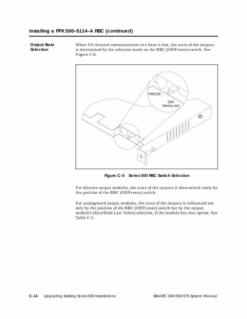
Upgrading Existing Series 500 InstallationsC-14 SIMATIC 545/555/575 System Manual
Installing a PPX:500–5114–A RBC (continued)
When I/O channel communication to a base is lost, the state of the outputsis determined by the selection made on the RBC (Off/Freeze) switch. SeeFigure C-6.
FREEZE
OFF(factory set)
Figure C-6 Series 500 RBC Switch Selection
For discrete output modules, the state of the outputs is determined solely bythe position of the RBC (Off/Freeze) switch.
For analog/word output modules, the state of the outputs is influenced notonly by the position of the RBC (Off/Freeze) switch but by the outputmodule’s (Zero/Hold Last Value) selection, if the module has that option. SeeTable C-1.
Output StateSelection

Upgrading Existing Series 500 Installations C-15SIMATIC 545/555/575 System Manual
Table C-1 Analog/Word Output States
RBC Off/Freeze Selection Analog/Word ModuleZero/Hold Selection
Analog/WordOutput State
Off Zero Zero *
Off Hold Last Value Last Value
Off – no selection – Last Value
Freeze Zero Last Value
Freeze Hold Last Value Last Value
Freeze – no selection – Last Value
* See the user manual of your analog/word output module for further details.
Notice that the Freeze option on the RBC overrides the Zero selection on theanalog/word output module; likewise, when Hold Last Value is selected onthe analog/word output module, that selection overrides the Off option onthe RBC jumper.
NOTE: If the RBC watchdog timer is activated (an RBC failure), the state ofthe outputs is determined by the output module, with no reference to theRBC’s Off/Freeze switch. Discrete outputs go off (to a value of zero).Analog/word outputs obey their own Zero/Hold Last Value selection. If noZero/Hold Last Value selection is available on the module, the analog/wordoutputs hold their last value.
NOTE: The DBC being replaced and previous models of the RBCautomatically set all discrete outputs to Off (0) and froze analog outputsunless the output module had a ZERO/HOLD LAST VALUE option.

Upgrading Existing Series 500 InstallationsC-16 SIMATIC 545/555/575 System Manual
Installing a PPX:500–5114–A RBC (continued)
As shown in Figure C-7, the display at the top of the module indicates thestatus of the Series 500 RBC.
Baud rate thumbwheel
Base thumbwheel
LED display
RemoteBase
Controller
Thumbwheel BaudNumber Rate
0 9600. . . . . . . . 1 2400. . . . . . . . 2 1200. . . . . . . . 3 300. . . . . . . . . 4 19200. . . . . . . 5 19200. . . . . . . 6 19200. . . . . . . 7 19200. . . . . . . 8 9600. . . . . . . . 9 2400. . . . . . . .
10 1200. . . . . . . . 11 300. . . . . . . . . 12 19200. . . . . . . 13 19200. . . . . . . 14 19200. . . . . . . 15 19200. . . . . . .
RS-485 I/O port 9-pin female
RS-232 port 25-pin female
Figure C-7 Series 500 Remote Base Controller and Baud Rate Settings
Status is displayed in integer format; see Table C-2 for definitions.
Table C-2 Series 500 RBC LED Messages
Display Definitions Display Definitions
0 RBC Good 5 Not Used
1 Self Diagnostics Failure 6 Not Used
2 Module Mismatch 7 Communication Good, NotConfigured
3 I/O Communication TimeOut
8 Watchdog Timer Expired
4 RAM Parity Error
The RBC is equipped with a RS-232 port that allows you to program theSeries 505 CPU or to troubleshoot from a remote I/O base. A baud ratethumbwheel, shown in Figure C-7, is used to set the baud rate for this port.
Status Display
Setting Baud Rates

Upgrading Existing Series 500 Installations C-17SIMATIC 545/555/575 System Manual
The base thumbwheel shown in Figure C-7 is used to reset the Series 500RBC during system operation and to assign the base address.
! WARNINGIf you reset the RBC when the system is operating, the RBC is logged off thesystem. When the RBC is logged off, inputs and outputs associated with thebase are affected, as described below. If you do not take the condition of yourinputs and outputs into account, logging the RBC off the system can causeunpredictable process operation.
Unpredictable process operation can cause death or serious injury topersonnel, and/or damage to equipment.
Do not reset your RBC unless you understand and are prepared for theconsequences (described below).
If you want to use the base thumbwheel switch to reset the Series 500 RBCwhile the system is operating, momentarily change the switch to anothernumber, then quickly return it to the correct base address setting.
The following actions take place when an RBC is reset.
• The CPU logs the RBC off the system and zeros the image registerpoints which represent the inputs from this RBC’s base. The imageregister is zeroed out until the RBC completes reset and resumescommunication with the CPU. If this occurs while the system isoperating, depending on your RLL program, turning these inputs offcould affect other base outputs.
• From the assertion of reset until the RBC completes the reset andresumes communication with the CPU, the state of the outputs on thisRBC’s base is determined by the output module, with no reference tothe RBC’s Off/Freeze switch. Discrete outputs go off (to a value of zero).Analog/word outputs obey their own Zero/Hold Last Value selection. Ifno Zero/Hold Last Value selection is available on the module, theanalog/word outputs hold their last value.
• If the base number you assign to the RBC (by setting the basethumbwheel) inadvertently duplicates the number already in use by asecond RBC on the I/O channel, when the first RBC completes its resetand attempts to communicate, identifying itself with the new basenumber, the second RBC will be logged off the system. The state of thesecond RBC’s outputs is determined by the selection made on the RBC’sOff/Freeze switch. The CPU image register containing the input pointsfor the second RBC is zeroed. Intermittent operation could occur aslong as the two RBC base thumbwheels are set to the same number.
Using the BaseThumbwheel
Resetting the RBC

Upgrading Existing Series 500 InstallationsC-18 SIMATIC 545/555/575 System Manual
Installing a PPX:500–5114–A RBC (continued)
When the CPU logs an RBC off the system, it sets a corresponding bit in oneof the status words that are available to your RLL program. Your RLLprogram can use these bits to detect the loss of the RBC and control theoutputs of other bases as appropriate for your application. For details aboutstatus words and more information about programming, refer to theSIMATIC 505 Programming Reference User Manual.
The base thumbwheel switch shown in Figure C-7 is used to assign a basenumber to the RBC for system identification. If you are using more than oneRBC, each RBC must be uniquely numbered. Refer to Table C-3 whenassigning base numbers. Base number 0 is reserved for the local base(Series 505 controller) and must not be assigned to the RBC.
Table C-3 Base Numbers
ThumbwheelNumber Base Number Thumbwheel
Number Base Number
Do Not Use 0* 8 8
1 1 9 9
2 2 10 10
3 3 11 11
4 4 12 12
5 5 13 13
6 6 14 14
7 7 15 15
* Base 0 is reserved for local base assignment. Therefore, do not assign baseaddress 0 to the Series 500 RBC.
Assigning BaseNumbers

Upgrading Existing Series 500 Installations C-19SIMATIC 545/555/575 System Manual
C.6 RS-485/RF I/O Channel Converter
The RS-485/RF (Coaxial) I/O Channel Converter, PPX:505–6860, allows youto use coaxial cables in a Series 505 system, thereby extending themaximum cable distance to 4 km. The converter connects a Series 505RS-485 remote I/O interface to an RF remote I/O interface, and makes itpossible to go from a Series 505 local base either to a Series 500 remote basethat has RF media or to a dual media remote base.
For more information about using dual media with Series 505 remote bases,refer to the SIMATIC 505 Redundant I/O Systems User Manual,PPX:505–8125–x.
Your RBC must have firmware Rel. 3.0 or later if you use either the dualmedia option or PCS 3.0 or later.
The RS-485/RF I/O channel converter is compatible with the followingCPUs:
• 545–1104 and 545–1106 CPUs
• 555–1103, 555–1104, 555–1105, and 5550–1106 CPUs
• 575–2104, 575–2105, and 575–2106 CPUs with installed PPX:575–2126annex card.
NOTE: The RS-485/RF I/O channel converter is compatible only with RBCsusing the Series 505 remote I/O channel and Series 505/Series 500 remoteI/O, such as the PPX:505–6850–A and PPX:500–2114–A RF, dual-media-compatible RBCs. The converter is not compatible with the 505PROFIBUS-DP RBC or other products that use the PROFIBUS-DP I/Ochannel.
Introduction
Compatibility

Upgrading Existing Series 500 InstallationsC-20 SIMATIC 545/555/575 System Manual
RS-485/RF I/O Channel Converter (continued)
Use the following procedure to install the PPX:505–6860.
1. Remove the power from the base in which you are installing thePPX:505–6860.
! WARNINGDisable all power to the base before installing or removing the PPX:505–6860.
Installing or removing any module from a powered-up base could causeunexpected operation which could cause death or serious injury to personnel,and/or damage to equipment.
To prevent disruption of the I/O channel, disconnect the I/O channel cablebefore removing or installing the PPX:505–6860.
2. In the case of a 545–1104, 555–1103, or 555–1104 installation, installthe PPX:505–6860 in the same base as the CPU, in the first double I/Oslot adjacent to the CPU.
In the case of a 575–2104 installation, the PPX:505–6860 must beinstalled in a Series 505 base within three feet of the 575 base that iselectrically bonded to the Series 505 base.
CAUTIONThe PPX:505–6860 is sensitive to, and can be damaged by, electrostaticdischarge.
Ensure that personnel make contact with a static-dissipative pad and/or wear agrounded wrist strap when handling the PPX:505–6860.
3. Position the PPX:505–6860 so that the bezel is facing you.
4. Grasp the top and bottom of the PPX:505–6860.
5. Carefully push the PPX:505–6860 into the slot until it mates with thebackplane connector.
6. Tighten top and bottom bezel screws.
CAUTIONThe PPX:505–6860 is not designed to be installed in a VME base.
Doing so results in damage to equipment.
Never attempt to install the PPX:505–6860 in a VME base.
Installing theRS-485/RFI/O ChannelConverter

Upgrading Existing Series 500 Installations C-21SIMATIC 545/555/575 System Manual
To remove the PPX:505–6860, complete the following steps.
1. If attached, remove cables from the front of the PPX:505–6860.
2. Disconnect power to the base.
! WARNINGDisable all power to the base before installing or removing the PPX:505–6860.
Installing or removing any module from a powered-up base could causeunexpected operation which could cause death or serious injury to personnel,and/or damage to equipment.
To prevent disruption of the I/O channel, disconnect the I/O channel cablebefore removing or installing the PPX:505–6860.
3. Loosen top and bottom bezel screws.
4. Carefully pull the PPX:505–6860 from the base.
CAUTIONThe PPX:505–6860 is sensitive to, and can be damaged by, electrostaticdischarge.
Ensure that personnel make contact with a static-dissipative pad and/or wear agrounded wrist strap when handling the PPX:505–6860.
Removing theRS-485/RFI/O ChannelConverter

Upgrading Existing Series 500 InstallationsC-22 SIMATIC 545/555/575 System Manual
RS-485/RF I/O Channel Converter (continued)
Use the following instructions to install cables for the PPX:505–6860:
NOTE: Since 545–1104, –1106, 555–1103, –1104, –1105, –1106 and575–2104, –2105, –2106 CPUs use RS-485 cabling, the RS-485/RF I/Ochannel converter is only needed if you are connecting the CPU to an RFremote base. The CPU can be connected directly to an RS-485 remote base.
1. Use an RS-485 cable to connect the CPU’s RS-485 I/O port to theconverter’s RS-485 I/O port.
The cable should be as short as possible. You cannot connect any otherdevices on this RS-485 cable; it is not possible to operate an RS-485 I/Olink with an RF converter and RF link. Notice that the connectionrequires two twisted, shielded pairs with 9-pin, subminiature, maleD-connectors at each end, rather than the single pair cable that is usedfor an RS-485 Series 505 remote I/O channel.
Suggested cable types include the following:
Alpha #5472 2TP w/shield 24 AWGBelden #9502 2TP w/shield 24 AWG
Table C-4 shows the pinout specifications for the cable that connectsfrom the CPU to the RS-485/RF I/O channel converter. Pair like-namedsignals 3 and 8, and 4 and 9.
Table C-4 Pinout Specifications
CPUConnector Pin
ModuleConnector Pin Description
5 5 Ground (Shields)
3 3 D485–
4 4 RTS485–
8 8 D485
9 9 RTS485
Cabling

Upgrading Existing Series 500 Installations C-23SIMATIC 545/555/575 System Manual
2. Connect the RF (coaxial) cable to the PPX:505–6860 port that is labeledRF To I/O BASES. See Figure C-8.
RS-485/RFI/O ChannelConverter
RS-485 I/OFrom PLC
RF ToI/O BASES
505–6860
Figure C-8 RS-485/RF Connector Ports

Series 505 and VME Components D-1SIMATIC 545/555/575 System Manual
Appendix D
Series 505 and VME Components
D.1 Series 505 System Components D-2. . . . . . . . . . . . . . . . . . . . . . . . . . . . . . . . . . . . . . . . . . . . . . . . . .
D.2 575 VME System Components D-5. . . . . . . . . . . . . . . . . . . . . . . . . . . . . . . . . . . . . . . . . . . . . . . . . . .
D.3 Recommended Spare Parts D-6. . . . . . . . . . . . . . . . . . . . . . . . . . . . . . . . . . . . . . . . . . . . . . . . . . . . . Spares for Series 505 System D-6. . . . . . . . . . . . . . . . . . . . . . . . . . . . . . . . . . . . . . . . . . . . . . . . . . . . . Spares for 575 System D-7. . . . . . . . . . . . . . . . . . . . . . . . . . . . . . . . . . . . . . . . . . . . . . . . . . . . . . . . . . .

Series 505 and VME ComponentsD-2 SIMATIC 545/555/575 System Manual
D.1 Series 505 System Components
Table D-1 lists components used in Series 505 systems.
Table D-1 Series 505 System Components
Component Part Number Description
PPX:545–1103 / –1105 96 Kbyte RAM CPU w/12 MHz 68020 processor
PPX:545–1104 / –1106 192 Kbyte RAM CPU w/12 MHz 68020 processor
PPX:555–1103 384 Kbyte RAM CPU w/25 MHz 68020 processorCPUs
PPX:555–1104 1920 Kbyte RAM CPU w/25 MHz 68020 processor
PPX:555–1105 384 Kbytes; 25 MHz; math coprocessor, PowerMath; SmarTune
PPX:555–1106 1856 Kbytes; 25 MHz; math coprocessor, PowerMath; SmarTune
PPX:505–2580 16 input, 120 VAC, isolated
PPX:505–2590 16 output, 24–120 VAC, isolated
PPX:505–3508 8 output, 4.5–34 VDC, 0.5 A, 2 outputs/common (sinking)
PPX:505–3516 16 output, 4.5–34 VDC, 0.5 A, 4 outputs/common (sinking)
PPX:505–3532 32 output, 4.5–34 VDC, 0.5 A, 8 outputs/common (sinking)
PPX:505–3708 8 output, 4.5–34 VDC, 2 A, 2 outputs/common (sinking)
PPX:505–3716 16 output, 4.5–34 VDC, 2 A, 4 outputs/common (sinking)
PPX:505–3732 32 output, 4.5–34 VDC, 2 A, 8 outputs/common (sinking)
PPX:505–4008–A 8 input, 20–56 VAC, 2 inputs/common
PPX:505–4016–A 16 input, 20–56 VAC, 4 inputs/common
PPX:505–4032–A 32 input, 20–56 VAC, 8 inputs/common
PPX:505–4108 8 input, 4–15 VDC, 2 inputs/common
PPX:505–4116 16 input, 4–15 VDC, 4 inputs/common
Discrete PPX:505–4132 32 input, 4–15 VDC, 8 inputs/commonDiscreteI/O Modules PPX:505–4208–A 8 input, 79–132 VAC, 2 inputs/common
PPX:505–4216–A 16 input, 79–132 VAC, 4 inputs/common
PPX:505–4232–A 32 input, 79–132 VAC, 8 inputs/common
PPX:505–4308 8 input, 14–30 VDC, 2 inputs/common
PPX:505–4316–A 16 input, 14–30 VDC and 42–56 VDC
PPX:505–4317 16 input, 10–33 VDC, isolated/interrupt
PPX:505–4318 16 input, 48 VDC, isolated/interrupt
PPX:505–4319 16 input, 125 VDC, isolated/interrupt
PPX:505–4332 32 input, 14–30 VDC, 8 inputs/common
PPX:505–4408 8 input, 164–265 VAC, 2 inputs/common
PPX:505–4408–A 8 input, 164–265 VAC, 2 inputs/common
PPX:505–4416–A 16 input, 164–265 VAC, 4 inputs/common
PPX:505–4432–A 32 input, 164–265 VAC, 8 inputs/common
PPX:505–4508 8 output, 4.5–34 VDC, 0.5 A, 2 outputs/common

Series 505 and VME Components D-3SIMATIC 545/555/575 System Manual
Table D-1 Series 505 System Components (continued)
Component Part Number Description
PPX:505–4516 16 output, 4.5–34 VDC, 0.5 A, 4 outputs/common
PPX:505–4532 32 output, 4.5–34 VDC, 0.5 A, 8 outputs/common
PPX:505–4608 8 output, 20–132 VAC, 0.5 A, 2 outputs/common
PPX:505–4616 16 output, 20–132 VAC, 0.5 A, 4 outputs/common
PPX:505–4632 32 output, 20–132 VAC, 0.5 A, 8 outputs/common
PPX:505–4708 8 output, 4.5–34 VDC, 2 A, 2 outputs/common
PPX:505–4716 16 output, 4.5–34 VDC, 2 A, 4 outputs/common
PPX:505–4732 32 output, 4.5–34 VDC, 2 A, 8 outputs/common
Discrete PPX:505–4808 8 output, 85–265 VAC, 2 A, 2 outputs/commonDiscreteI/O Modules PPX:505–4816 16 output, 85–265 VAC, 2 A, 4 outputs/common
PPX:505–4832 32 output, 85–265 VAC, 2 A, 8 outputs/common
PPX:505–4908 8 output, Form C, 20–265 VAC or 4.5–30 VDC
PPX:505–4916 16 output NO, 20–265 VAC or 4.5–30 VDC, 8 outputs/common
PPX:505–4932–A 32 output NO, 20–265 VAC or 4.5–30 VDC, 8 outputs/common
PPX:505–5417 16 output, Form C, 120 VAC (10–125 VAC), relay out
PPX:505–5518 16 output, Form C, 120 VAC, high-current, relay out
PPX:505–6010 32 input, simulator
PPX:505–6011 32 output, simulator
PPX:505–2555 16 input, analog, 14-bit, differential
PPX:505–2556 16 input, Thermocouple with open T/C detect
PPX:505–2557 16 input, RTD with open sensor detect
PPX:505–6108–A/B 8 input, analog, 12-bit, single-ended
PPX:505–6208–A/B 8 output, analog, 12-bit, single-endedAnalog & Word
I/O ModulesPPX:505–6308 8 input, BCD word
I/O ModulesPPX:505–6408 8 output, BCD word
PPX:505–7012 8 input/4 output, analog
PPX:505–7016 8 input/4 output, analog, bipolar voltage outputs
PPX:505–7028–A 8 input, Thermocouple, isolated
PPX:505–7038 8 input, Resistance Temperature Detector
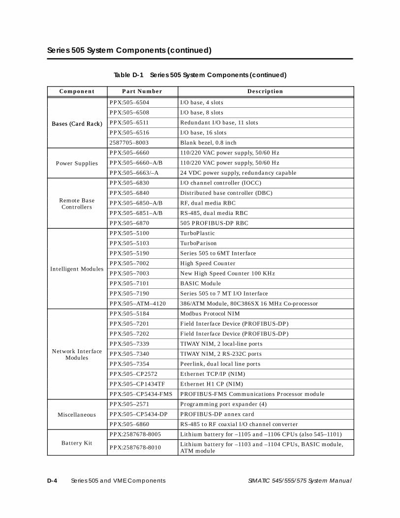
Series 505 and VME ComponentsD-4 SIMATIC 545/555/575 System Manual
Series 505 System Components (continued)
Table D-1 Series 505 System Components (continued)
Component Part Number Description
PPX:505–6504 I/O base, 4 slots
PPX:505–6508 I/O base, 8 slots
Bases (Card Rack) PPX:505–6511 Redundant I/O base, 11 slotsBases (Card Rack)PPX:505–6516 I/O base, 16 slots
2587705–8003 Blank bezel, 0.8 inch
PPX:505–6660 110/220 VAC power supply, 50/60 Hz
Power Supplies PPX:505–6660–A/B 110/220 VAC power supply, 50/60 Hz
PPX:505–6663/–A 24 VDC power supply, redundancy capable
PPX:505–6830 I/O channel controller (IOCC)
PPX:505–6840 Distributed base controller (DBC)Remote Base PPX:505–6850–A/B RF, dual media RBCControllers
PPX:505–6851–A/B RS-485, dual media RBC
PPX:505–6870 505 PROFIBUS-DP RBC
PPX:505–5100 TurboPlastic
PPX:505–5103 TurboParison
PPX:505–5190 Series 505 to 6MT Interface
PPX:505–7002 High Speed CounterIntelligent Modules
PPX:505–7003 New High Speed Counter 100 KHz
PPX:505–7101 BASIC Module
PPX:505–7190 Series 505 to 7 MT I/O Interface
PPX:505–ATM–4120 386/ATM Module, 80C386SX 16 MHz Co-processor
PPX:505–5184 Modbus Protocol NIM
PPX:505–7201 Field Interface Device (PROFIBUS-DP)
PPX:505–7202 Field Interface Device (PROFIBUS-DP)
PPX:505–7339 TIWAY NIM, 2 local-line portsNetwork Interface PPX:505–7340 TIWAY NIM, 2 RS-232C ports
ModulesPPX:505–7354 Peerlink, dual local line ports
PPX:505–CP2572 Ethernet TCP/IP (NIM)
PPX:505–CP1434TF Ethernet H1 CP (NIM)
PPX:505–CP5434-FMS PROFIBUS-FMS Communications Processor module
PPX:505–2571 Programming port expander (4)
Miscellaneous PPX:505–CP5434-DP PROFIBUS-DP annex card
PPX:505–6860 RS-485 to RF coaxial I/O channel converter
PPX:2587678-8005 Lithium battery for –1105 and –1106 CPUs (also 545–1101)Battery Kit
PPX:2587678-8010 Lithium battery for –1103 and –1104 CPUs, BASIC module,ATM module

Series 505 and VME Components D-5SIMATIC 545/555/575 System Manual
D.2 575 VME System Components
Table D-2 lists components used in 575 systems.
Table D-2 575 System Components
Component Part Number
VMEbus CPU: 832 Kbytes of user memory & fault relay; 12.5 MHz clock PPX:575–2104
VMEbus CPU: 832 Kbytes; built-in math coprocessor and PowerMath; 32 MHz clock PPX:575–2105
VMEbus CPU: 1856 Kbytes; built-in math coprocessor and PowerMath; 32 MHz clock PPX:575–2106
Sixteen-slot VMEbus base, 0.8-inch centers PPX:575–2130
Fan kit for PPX:575–2130 base, 115/230 VAC PPX:575–2131
VMEbus power supply, 185 W, 110 VAC only PPX:575–6660
VMEbus power supply, 300 W, 110/220 VAC PPX:575–6663
Series 505 Remote I/O annex card PPX:575–2126
PROFIBUS-DP annex card PPX:505–CP5434–DP
Discrete VMEbus 32-point, 110 V, AC input module PPX:575–4232
Discrete VMEbus 32-point, 24 V, DC input module PPX:575–4332
Discrete VMEbus 16 input/16 output, 24 V, 0.5 A, DC module PPX:575–4366
Discrete VMEbus 32-point, 24 V, 0.5 A, DC output module PPX:575–4532
Discrete VMEbus 16-point, 110 V, 1 A, AC output module PPX:575–4616
Discrete VMEbus 32-point, 24 V 2.0 A, DC output module PPX:575–4732
Discrete 16-point, relay output module PPX:575–4916
Male-to-male programming cable, 25-pin PPX:VPU200–3605
Support rail, 9-slot, 1-inch center base PPX:2589739–8001
Support rail, 14-slot, 1-inch center base PPX:2589739–8002
0.2-inch filler panel for 1-inch bases PPX:2589739–8004
0.4-inch filler panel for 1-inch bases PPX:2589739–8005
0.6-inch filler panel for all bases PPX:2589739–8015
0.8-inch filler panel for all bases PPX:2589739–8014
1.0-inch filler panel for 1-inch bases PPX:2589739–8003
Battery (4 V, 5 Ah) for all bases PPX:2589739–8006
I/O connector, front access PPX:2589739–8007
MC68882 math co-processor (12.5 mHz; for 575–2104 CPU) PPX:2589739–8010
Daisy chain jumper for 1-inch bases PPX:2589739–8011
Mounting rails for 0.8-inch base PPX:2589739–8016
575 J2 power connector kit PPX:2589739–8012

Series 505 and VME ComponentsD-6 SIMATIC 545/555/575 System Manual
D.3 Recommended Spare Parts
Siemens Energy & Automation, Inc., recommends that you maintain a 10%surplus of your system’s I/O modules as available spare parts. Dependingupon the number and type of CPUs that you have installed, you may wish tostock an extra controller as well. Additional spare parts, depending uponyour site configuration, can include items like fuses, back-up batteries,blank filler bezels, and spare bases.
The following is the recommended list of spare parts for a Series 505system:
• PPX:505–6504 base, 4 I/O slots
• PPX:505–6508 base, 8 I/O slots
• PPX:505–6511 base (19-inch rack compatible), 11 I/O slots
• PPX:505–6516 base (19-inch rack compatible), 16 I/O slots
• PPX:505–6660A or PPX:505–6663 power supply module
• PPX:2587679–8015, 3.0 A/250 V, slow-blow fuse (3AG) forPPX:505–6660A, qty. 5
• PPX:2587679–8018, 8.0 A/250 V, normal-blow fuse (3AG) forPPX:505–6663, qty. 5
• PPX:2601094–8001, RS-232–C/RS-423 9-to-9 pin programming cable
• EEPROM, 128K x 8, PPX:2587681–8022EEPROM, 256K x 8, PPX:2587681–8030
• EPROM, 128K x 8, PPX:2587681–8023EPROM, 256K x 8, PPX:2587681–8031
• Battery Kit for 545–1103/–1104 CPUs, 555–1103/–1104 CPUs,505–7101 BASIC Module, and 505 ATM Module: PPX:2587678–8010
• Battery Kit for 545–1105/–1106 CPUs, 555–1105/–1106 CPUs,545–1101 CPU, 560/565 CPUs, Series 500 CPUs: PPX:2587678–8005
Spares for Series505 System

Series 505 and VME Components D-7SIMATIC 545/555/575 System Manual
The following is the recommended list of spare parts for a 575 system:
• PPX:575–2130, 16-slot VME base with 0.8-inch spacing
• PPX:575–2131, 115/230 VAC fan kit for 751–2130 base
• PPX:575–6660, 185-watt power supply module
• PPX:575–6663, 300-watt power supply module
• PPX:2587679–8016, 4.0 A fuse kit for battery on all VME bases
• PPX:2589739–8008, 8.0 A/250 V, slow-blow fuse (3 AG) forPPX:575–6660, qty. 5
• PPX:2589739–8013, 10.0 A/250 V, slow-blow fuse (3 AG) forPPX:575–6663, qty .5
• PPX:2587679–8019, 5.0 A/125 V, normal-blow fuse (5 x 20 mm) forPPX:575–4616, PPX:575–4366, and PPX:575–4532)
• PPX:2587679–0310, 3.0 A, normal-blow fuse (5 x 20 mm) forPPX:575–4916, qty. 5
• PPX:2587679–8020, 8.0 A, normal-blow fuse (5 x 20 mm) forPPX:575–4732, qty. 5
• PPX:2587679–8002, 3.0 A fuse kit for 575–2131 fan pack
• PPX:2589739–8006, battery pack, 4 V, 5 Ah gel cell
• PPX:2589739–8016, Z-rails, DIN connector rail kit with hardware,qty. 2
• PPX:2589739–8012, 575 J2 power connector kit
• PPX:2589739–8014, 0.8-inch blank filler bezel, qty. 1
• PPX:2589739–8015, 0.6-inch blank filler bezel, qty. 1
Spares for 575System

575 I/O Module Specification & Pinouts E-1SIMATIC 545/555/575 System Manual
Appendix E
575 I/O Module Specifications & Pinouts
E.1 Discrete AC Input Module E-2. . . . . . . . . . . . . . . . . . . . . . . . . . . . . . . . . . . . . . . . . . . . . . . . . . . . . . .
E.2 16 Input/16 Output 24 VDC Module E-4. . . . . . . . . . . . . . . . . . . . . . . . . . . . . . . . . . . . . . . . . . . . . .
E.3 Discrete AC Output Module E-7. . . . . . . . . . . . . . . . . . . . . . . . . . . . . . . . . . . . . . . . . . . . . . . . . . . . .
E.4 Discrete Relay Output Module E-9. . . . . . . . . . . . . . . . . . . . . . . . . . . . . . . . . . . . . . . . . . . . . . . . . . .
E.5 Discrete DC Output Module E-12. . . . . . . . . . . . . . . . . . . . . . . . . . . . . . . . . . . . . . . . . . . . . . . . . . . . .
E.6 Discrete DC Input Module E-15. . . . . . . . . . . . . . . . . . . . . . . . . . . . . . . . . . . . . . . . . . . . . . . . . . . . . . .

575 I/O Module Specification & PinoutsE-2 SIMATIC 545/555/575 System Manual
E.1 Discrete AC Input Module
The discrete AC input module (PPX:575–4232) enables the CPU to monitor110 VAC field inputs. Table E-1 lists the specifications of the discrete ACinput module. See Table E-2 for connector pinouts.
Table E-1 Discrete AC Input Module Specifications
Feature Description
Optical isolation 1500 Vrms
Isolation between commons 1500 Vrms
Chassis-to-user circuits 1500 Vrms
Inputs 32
Commons 4
Input type IEC type 1
On voltage 79.0 VAC UH minimum132.0 VAC UH maximum
Off voltage 0.0 VAC UL minimum20.0 VAC UL maximum
On input current limits 4.0 mA IH minimum15.0 mA IH maximum
Off input current 1.0 mA maximum
Module time-delay 4 ms minimum30 ms maximum
Operating frequency 47–63 Hz
+5 V base current consumption 0.9 A maximum
±12 V current consumption None
Vbatt current consumption(+5 V STDBY) None
Indicators On-state indicators, one per channel.No fuses, so blown-fuse indicators are not used

575 I/O Module Specification & Pinouts E-3SIMATIC 545/555/575 System Manual
Table E-2 shows connector pinouts for a discrete AC input module.
Table E-2 Discrete AC Input Module Connector Pinouts
Pin Signal LED
AR Input section A return —A1 Input 1 A1A2 Input 2 A2A3 Input 3 A3A4 Input 4 A4A5 Input 5 A5A6 Input 6 A6A7 Input 7 A7A8 Input 8 A8BR Input section B return —B1 Input 9 B1B2 Input 10 B2B3 Input 11 B3B4 Input 12 B4B5 Input 13 B5B6 Input 14 B6B7 Input 15 B7B8 Input 16 B8CR Input section C return —C1 Input 17 C1C2 Input 18 C2C3 Input 19 C3C4 Input 20 C4C5 Input 21 C5C6 Input 22 C6C7 Input 23 C7C8 Input 24 C8DR Input section D return —D1 Input 25 D1D2 Input 26 D2D3 Input 27 D3D4 Input 28 D4D5 Input 29 D5D6 Input 30 D6D7 Input 31 D7D8 Input 32 D8NOTE: AC, BC, CC, DC are not connected

575 I/O Module Specification & PinoutsE-4 SIMATIC 545/555/575 System Manual
E.2 16 Input/16 Output 24 VDC Module
The discrete DC 16 input/16 output module (PPX:575–4366) lets you drive24 VDC sinking loads and monitor 24 VDC source inputs. Table E-3 showsthe module isolation specifications.
Table E-3 24 VDC I/O Module Isolation
Feature Description
Optical isolation 1500 Vrms
Isolation between commons 1000 Vrms
Chassis-to-user circuits 1000 Vrms
Figure E-1 illustrates the effect that temperature has on current outputcapabilities.
0.0
0.1
0.2
0.3
0.4
0.5
0.6
0 10 20 30 40 50 60 70
With fan cooling Without fan cooling
Cur
rent
(A
)
Cur
rent
(A
)
8 on
16 on
16 on
Temperature (°C)Temperature (°C)
0.0
0.1
0.2
0.3
0.4
0.5
0.6
0 10 20 30 40 50 60 70
Figure E-1 Low-Current DC Output: Current/Point vs. Ambient Temp

575 I/O Module Specification & Pinouts E-5SIMATIC 545/555/575 System Manual
Specifications for the discrete DC 16 input/16 output module are shown inTable E-4. See Table E-5 for the connector pinouts.
Table E-4 16 Input/16 Output Module Specifications
Feature Description
+5 V base current consumption 0.9 A (maximum)
±12 V current consumption None
VBatt (+5 V STDBY) currentconsumption None
Outputs 16
Commons 2
FusesOne 5 A, 125 V, normal-blow, 5x20 mmfuse per output common.Replace only with UL/CSA-listed fuse.
Output type Non-latching, unprotected
Operating voltage range 14–36 VDC
Maximum off-state leakage current 0.2 mA
Maximum on-state voltage drop 1.8 VDC
Minimum load per point 1.0 mA at 24 VDC
Inductive load kickback Diode-protected
Maximum time-delay 2 ms on to off with 5 mA load2 ms off to on with 5 mA load
Temporary overload 2.0 A for 1 ms
User power 3.0 mA maximum per common withzero load
Indicators
On-state indicators, one per channel.One blown fuse indicator, which lightswhen any fuse blows (user power andbase power must be on)
Inputs 16
Commons 2
Input type IEC type 1
On voltage 14.0 VDC UH min36.0 VDC UH max
Off voltage 0.0 VDC UL min5.0 VDC UL max
On input current limits 2.0 mA IH min15.0 mA IH max
Off input current 0.5 mA max
Module time-delay 0.65 ms min5 ms max
Indicators On-state indicators, one per channel

575 I/O Module Specification & PinoutsE-6 SIMATIC 545/555/575 System Manual
16 Input/16 Output 24 VDC Module (continued)
Table E-5 16 Input/16 Output Module Connector Pinouts
Pin Signal LED
AR Input section A return —A1 Input 1 A1A2 Input 2 A2
A3 Input 3 A3A4 Input 4 A4
A5 Input 5 A5A6 Input 6 A6A7 Input 7 A7
A8 Input 8 A8BR Input section B return —
B1 Input 9 B1B2 Input 10 B2
B3 Input 11 B3B4 Input 12 B4
B5 Input 13 B5B6 Input 14 B6B7 Input 15 B7
B8 Input 16 B8CR Output section C return —
C1 Output 1 C1C2 Output 2 C2
C3 Output 3 C3C4 Output 4 C4
C5 Output 5 C5C6 Output 6 C6C7 Output 7 C7
C8 Output 8 C8CC Output section C user power —
DR Output section D return —D1 Output 9 D1
D2 Output 10 D2D3 Output 11 D3D4 Output 12 D4
D5 Output 13 D5D6 Output 14 D6
D7 Output 15 D7D8 Output 16 D8
DC Output section D user power —NOTE: AC and BC are not connected.

575 I/O Module Specification & Pinouts E-7SIMATIC 545/555/575 System Manual
E.3 Discrete AC Output Module
The discrete AC output module (PPX:575–4616) allows the controller todrive 110 VAC loads. Table E-6 shows module specifications, and Figure E-2illustrates the effect that temperature has on current output capabilities.Table E-7 shows connector pinouts.
Table E-6 Discrete AC Output Module Specifications
Feature Description
Optical isolation 1500 Vrms
Isolation between commons 1500 Vrms
Chassis-to-user circuits 1500 Vrms
Outputs 16
Commons 4
FusesOne 5 A, 125 V, normal-blow, 5x20 mmfuse per common.Replace only with UL/CSA-listed fuse.
Output type Non-latching, unprotected
Surge suppression R-C
Operating voltage range 79–132 VAC
Maximum off-state leakage current 2 mA at 110 VAC
Maximum on-state voltage drop 1.8 VAC, 0–peak, at 1 A
Minimum load per point 10.0 mA at 110 VAC
Maximum time-delay 1/2 cycle on/off, off/on
Temporary overload 5.0 A rms for 2 cycles
Maximum dv/dt for main triac 200 V/µs
Operating frequency 47–63 Hz
+5 V base current consumption 0.9 A max
±12 V current consumption None
VBatt (+5 V STDBY) currentconsumption None
Indicators
On-state indicators, one per channel.One blown fuse indicator, which lightswhen any fuse blows (user power andbase power must be on).Indicators A5–A8, B5–B8, C5–C8, andD5–D8 are unused

575 I/O Module Specification & PinoutsE-8 SIMATIC 545/555/575 System Manual
Discrete AC Output Module (continued)
Figure E-2 illustrates the effect that temperature has on current outputcapabilities. Table E-7 shows connector pinouts.
0.0
0.2
0.4
0.6
0.8
1.0
1.2
0 10 20 30 40 50 60 70
With fan cooling Without fan cooling
Cur
rent
(A
)
Cur
rent
(A
)
0.0
0.2
0.4
0.6
0.8
1.0
1.2
0 10 20 30 40 50 60 70
8 on
16 on16 on
Temperature (°C) Temperature (°C)
Figure E-2 16-point AC Output: Current/Point vs. Ambient Temp
Table E-7 Discrete AC 16-point Output Module Connector Pinouts
Pin Signal LED
AR Output section A return —
A1 Output 1 A1
A2 Output 2 A2
A3 Output 3 A3
A4 Output 4 A4
AC Output section A user power —
BR Output section B return —
B1 Output 5 B1
B2 Output 6 B2
B3 Output 7 B3
B4 Output 8 B4
BC Output section B user power —
CR Output section C return —
C1 Output 9 C1
C2 Output 10 C2
C3 Output 11 C3
C4 Output 12 C4
CC Output section C user power —
DR Output section D return —
D1 Output 13 D1
D2 Output 14 D2
D3 Output 15 D3
D4 Output 16 D4
DC Output section D user power —

575 I/O Module Specification & Pinouts E-9SIMATIC 545/555/575 System Manual
E.4 Discrete Relay Output Module
The discrete relay output module (PPX:575–4916) allows the controller todrive AC and DC loads of various voltage and current ranges. The loads canbe sourcing or sinking. Table E-8 shows module specifications.
Table E-8 Discrete Relay Output Module Specifications
Feature Description
Optical isolation 1500 Vrms
Isolation between commons 1500 Vrms
Isolation between chassis ground anduser circuits 1500 Vrms
Outputs 16
Commons 4
FusesOne 3 A, 250 V, normal-blow, 5 x 20 mmfuse per output (16 fuses total).Replace only with UL/CSA-listed fuse.
Output type Non-latching, unprotected
Type of contact Form A
Operating voltage range 4.5 to 36 VDC20 to 265 VAC
Maximum off-state leakage current 0.0 mA
Minimum load current per point 10.0 mA
Maximum delay time through module 10 ms, on to off;10 ms, off to on
Temporary overload * 5.0 A for 1 ms
Repetition rate 6 Hz maximum
Coil voltage requirement 24 VDC ±5% (22.8–25.2 V)
+5 V current consumption 0.9 A maximum
±12 V current consumption None
Vbatt current consumption(+5 V STDBY) None
Life cycles (@ 1 Hz repetition rate)Full rated current@ 0.5 A@ 0.1 A
100,000300,000
1,000,000
Maximum total relay contact resistance:—at 0.5 A to 2 A load currents = 400 mOhms—at 10 mA to 0.5 A load currents, use the following equation:
max R (ohms) = ((4.5 V/load current) x 0.05) + 0.15* The relay output module may be damaged if more than one channel isoverloaded at the same time, or if the temporary overload specification isexceeded.

575 I/O Module Specification & PinoutsE-10 SIMATIC 545/555/575 System Manual
Discrete Relay Output Module (continued)
Table E-9 shows connector pinouts for the discrete relay output module.
Table E-9 Discrete Relay Output Module Connector Pinouts
Pin Signal LED
AR Output section A return —
A1 Output 1 A1
A2 Output 2 A2
A3 Output 3 A3
A4 Output 4 A4
AC Output section A user power —
BR Output section B return —
B1 Output 5 B1
B2 Output 6 B2
B3 Output 7 B3
B4 Output 8 B4
BC Output section B user power —
CR Output section C return —
C1 Output 9 C1
C2 Output 10 C2
C3 Output 11 C3
C4 Output 12 C4
CC Output section C user power —
DR Output section D return —
D1 Output 13 D1
D2 Output 14 D2
D3 Output 15 D3
D4 Output 16 D4
DC Output section D user power —
C7 24 VDC user coil power (positive line from supply) —
C8 24 VDC user coil power return (return line to supply) —

575 I/O Module Specification & Pinouts E-11SIMATIC 545/555/575 System Manual
Figure E-3 shows a sample of field wiring for the discrete relay outputmodule.
Module FieldAC
A1
A2
A3
A4
AR
Terminal Block
Figure E-3 Field Wiring for Relay Output Module
Figure E-4 illustrates the effect that temperature has on current outputcapabilities.
0.0
0.5
1.0
1.5
2.0
2.5
0 10 20 30 40 50 60 70
With fan cooling Without fan cooling
Cur
rent
(A
)
Cur
rent
(A
)
0.0
0.5
1.0
1.5
2.0
2.5
0 10 20 30 40 50 60 70
8 on
16 on
Temperature (°C) Temperature (°C)
8 on
16 on
Figure E-4 Relay Output Module: Current/Point vs. Ambient Temp

575 I/O Module Specification & PinoutsE-12 SIMATIC 545/555/575 System Manual
E.5 Discrete DC Output Module
The discrete DC output modules (PPX:575–4532 and PPX:575–4732) allowthe controller to drive DC loads of various voltages. These modules aresourcing output modules. An LED indicator on the module faceplate signalsa blown fuse in the module. Table E-10 shows the module specifications, andFigure E-5 shows the effect that temperature has on current output, for thePPX:575–4532.
Table E-10 PPX:575–4532 Specifications
Feature Description
Optical isolation 1500 Vrms
Isolation between commons 500 Vrms
Isolation between chassis ground anduser circuits
1000 Vrms
Outputs 32
Commons 4
FusesOne 5 A, 125 V normal-blow, 5 x 20 mmfuse per common (4 fuses total).Replace only with UL/CSA-listed fuse.
Output type Non-latching, unprotected
Operating voltage range 4.5 to 36 VDC
Maximum off-state leakage current 0.2 mA
Maximum on-state voltage drop 1.8 VDC
Minimum load current per point 1.0 mA @ 24 VDC
Maximum delay time through module(with 5 mA load)
2 ms, on to off;2 ms, off to on
Inductive load kickback Diode protected
Temporary overload 2.0 A for 1 ms
+5 V base current consumption 1.0 A maximum
User power current (with no load) 3.0 mA maximum per common
With fan cooling Without fan cooling
Cur
rent
(A
)
Cur
rent
(A
)
0.0
0.1
0.2
0.3
0.4
0.5
0.6
0 10 20 30 40 50 60 70
50% on
All on
Temperature (°C) Temperature (°C)
0.0
0.1
0.2
0.3
0.4
0.5
0.6
0 10 20 30 40 50 60 70
All on
Figure E-5 PPX:575–4532: Current/Point vs. Ambient Temp

575 I/O Module Specification & Pinouts E-13SIMATIC 545/555/575 System Manual
Table E-11 shows the module specifications, and Figure E-6 shows the effectthat temperature has on current output, for the PPX:575–4732.
Table E-11 PPX:575–4732 Specifications
Feature Description
Optical isolation 1500 Vrms
Isolation between commons 500 Vrms
Isolation between chassis ground anduser circuits
1000 Vrms
Outputs 32
Commons 4
FusesOne 8 A, 125 V normal-blow, 5 x 20 mmfuse per common (4 fuses total).Replace only with UL/CSA-listed fuse.
Output type Non-latching, unprotected
Operating voltage range 4.5 to 36 VDC
Maximum off-state leakage current 0.2 mA
Maximum on-state voltage drop 2.2 VDC
Minimum load current per point 1.0 mA @ 24 VDC
Maximum delay time through module(with 5 mA load)
2 ms, on to off;2 ms, off to on
Inductive load kickback Diode protected
Temporary overload 5.0 A for 1 ms
+5 V base current consumption 1.0 A maximum
User power current (with no load) 3.0 mA maximum per common
0.0
0.5
1.0
1.5
2.0
0 10 20 30 40 50 60 70
With fan cooling Without fan cooling
Cur
rent
(A
)
Cur
rent
(A
)
Temperature (°C) Temperature (°C)
0.0
0.5
1.0
1.5
2.0
0 10 20 30 40 50 60 70
4 on
8 on
16 on
32 on
1 on
4 on
16 on32 on
Figure E-6 PPX:575–4732: Current/Point vs. Ambient Temp

575 I/O Module Specification & PinoutsE-14 SIMATIC 545/555/575 System Manual
Discrete DC Output Module (continued)
Table E-12 shows connector pinouts for both discrete DC output modules.
Table E-12 Discrete DC Output Module Connector Pinouts
Pin Signal LED
AR Output section A return (–) —A1 Output 1 A1A2 Output 2 A2A3 Output 3 A3A4 Output 4 A4A5 Output 5 A5A6 Output 6 A6A7 Output 7 A7A8 Output 8 A8AC Output section A user power (+) —BR Output section B return (–) —B1 Output 9 B1B2 Output 10 B2B3 Output 11 B3B4 Output 12 B4B5 Output 13 B5B6 Output 14 B6B7 Output 15 B7B8 Output 16 B8BC Output section B user power (+) —CR Output section C return (–) —C1 Output 17 C1C2 Output 18 C2C3 Output 19 C3C4 Output 20 C4C5 Output 21 C5C6 Output 22 C6C7 Output 23 C7C8 Output 24 C8CC Output section C user power (+) —DR Output section D return (–) —D1 Output 25 D1D2 Output 26 D2D3 Output 27 D3D4 Output 28 D4D5 Output 29 D5D6 Output 30 D6D7 Output 31 D7D8 Output 32 D8DC Output section D user power (+) —

575 I/O Module Specification & Pinouts E-15SIMATIC 545/555/575 System Manual
E.6 Discrete DC Input Module
The discrete low-voltage DC input module (PPX:575–4332) allows thecontroller to monitor user inputs of various DC voltages. An LED indicatoron the module faceplate signals a blown fuse in the module.
Table E-13 shows the module specifications.
Table E-13 Discrete DC Input Module Specifications
Feature Description
Optical isolation 1500 Vrms
Isolation between commons 1000 Vrms
Chassis-to-user circuits 1000 Vrms
Inputs 32
Commons 4
Input type IEC type 1
On voltage 14.0 VDC UH minimum36.0 VDC UH maximum
Off voltage 0.0 VDC UL minimum5.0 VDC UL maximum
On input current limits 2.0 mA IH minimum15.0 mA IH maximum
Off input current 0.5 mA maximum
Delay time through module 1 ms minimum5 ms maximum
+5 V current consumption 0.4 A maximum
Vbatt current consumption(+5 V STDBY) None
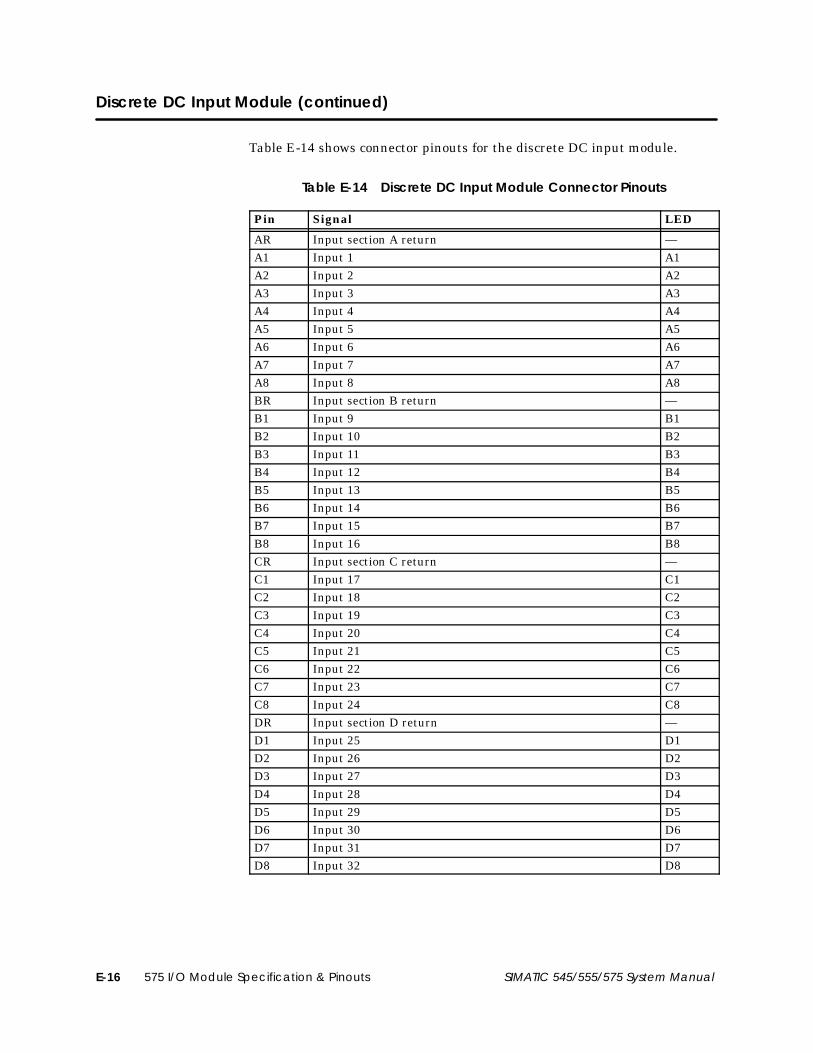
575 I/O Module Specification & PinoutsE-16 SIMATIC 545/555/575 System Manual
Discrete DC Input Module (continued)
Table E-14 shows connector pinouts for the discrete DC input module.
Table E-14 Discrete DC Input Module Connector Pinouts
Pin Signal LED
AR Input section A return —A1 Input 1 A1A2 Input 2 A2A3 Input 3 A3A4 Input 4 A4A5 Input 5 A5A6 Input 6 A6A7 Input 7 A7A8 Input 8 A8BR Input section B return —B1 Input 9 B1B2 Input 10 B2B3 Input 11 B3B4 Input 12 B4B5 Input 13 B5B6 Input 14 B6B7 Input 15 B7B8 Input 16 B8CR Input section C return —C1 Input 17 C1C2 Input 18 C2C3 Input 19 C3C4 Input 20 C4C5 Input 21 C5C6 Input 22 C6C7 Input 23 C7C8 Input 24 C8DR Input section D return —D1 Input 25 D1D2 Input 26 D2D3 Input 27 D3D4 Input 28 D4D5 Input 29 D5D6 Input 30 D6D7 Input 31 D7D8 Input 32 D8

Enhancements in Late Model CPUs F-1SIMATIC 545/555/575 System Manual
Appendix F
Enhancements in Late Model CPUs
F.1 Enhancements to Error Handling F-2. . . . . . . . . . . . . . . . . . . . . . . . . . . . . . . . . . . . . . . . . . . . . . . . . CPUs with Enhanced Firmware F-2. . . . . . . . . . . . . . . . . . . . . . . . . . . . . . . . . . . . . . . . . . . . . . . . . . Fatal Error Conditions F-2. . . . . . . . . . . . . . . . . . . . . . . . . . . . . . . . . . . . . . . . . . . . . . . . . . . . . . . . . . . Changes in Memory Error Handling F-2. . . . . . . . . . . . . . . . . . . . . . . . . . . . . . . . . . . . . . . . . . . . . . Using the Auto Recompile Function F-3. . . . . . . . . . . . . . . . . . . . . . . . . . . . . . . . . . . . . . . . . . . . . . Programming Support F-3. . . . . . . . . . . . . . . . . . . . . . . . . . . . . . . . . . . . . . . . . . . . . . . . . . . . . . . . . . .
F.2 Fast PROFIBUS-DP I/O Update Times F-4. . . . . . . . . . . . . . . . . . . . . . . . . . . . . . . . . . . . . . . . . . . . . . CPUs with this Feature F-4. . . . . . . . . . . . . . . . . . . . . . . . . . . . . . . . . . . . . . . . . . . . . . . . . . . . . . . . . . . Fast PROFIBUS-DP I/O Updates F-4. . . . . . . . . . . . . . . . . . . . . . . . . . . . . . . . . . . . . . . . . . . . . . . . . . . How it Works F-4. . . . . . . . . . . . . . . . . . . . . . . . . . . . . . . . . . . . . . . . . . . . . . . . . . . . . . . . . . . . . . . . . . . . Selecting Fast DP Update Mode F-4. . . . . . . . . . . . . . . . . . . . . . . . . . . . . . . . . . . . . . . . . . . . . . . . . Changing a PROFIBUS-DP Slave Configuration F-5. . . . . . . . . . . . . . . . . . . . . . . . . . . . . . . . . . . . Typical Update Time F-5. . . . . . . . . . . . . . . . . . . . . . . . . . . . . . . . . . . . . . . . . . . . . . . . . . . . . . . . . . . . Example F-5. . . . . . . . . . . . . . . . . . . . . . . . . . . . . . . . . . . . . . . . . . . . . . . . . . . . . . . . . . . . . . . . . . . . . . .
F.3 Memory Capacity of the 555–1106 CPU F-6. . . . . . . . . . . . . . . . . . . . . . . . . . . . . . . . . . . . . . . . . . Difference in Memory Capacity between the 555–1106 CPU and Earlier CPUs F-6. . . . . .

Enhancements in Late Model CPUsF-2 SIMATIC 545/555/575 System Manual
F.1 Enhancements to Error Handling
For the 555–1103/–1104 CPUs Release 4.2 or greater, 555–1105/–1106 CPUsRelease 5.2 or greater, 545–1105/–1106 CPUs Release 5.1 or greater, and575–2105/–2106 CPUs Release 5.1 or greater, the following changes in thefirmware have been implemented to minimize problems caused by excessnoise, as described below.
A few SIMATIC 505 customers have experienced an occasional CPU fatalerror (typically several months or more between failures on a specific CPU)that usually results in a TISOFT or SoftShop message such as “ProgramMemory Diagnostic Error.” These fatal errors generally occur in anenvironment that includes various equipment adjacent to the PLC such asUPS systems, variable speed drives and battery chargers. These types ofequipment often contain switching power supplies that can be sources ofhigh frequency electrical noise spikes, which may occasionally induce such afatal memory error condition.
While it is preferred that this electrical noise be eliminated throughsuppression or dissipation in an adequate grounding system, this may bedifficult to effect in many cases. At the same time, there are manycustomers who place a high value on “up time” and cannot justify a fatalerror unless it has a direct effect on the CPU operation.
The changes described in this section should provide a better solution foraffected customers, since this may reduce or even eliminate the problem forthem without the need to make changes to their systems. However, for mostof the customers who do not have this type of environment and have neverexperienced a Program Memory Diagnostic Error, there will be no noticeablechange.
When the SIMATIC 505 CPU diagnostics were originally written, it wasassumed that any memory error found was an indication of a hard memorychip failure, and the conservative approach of declaring a fatal error andshutting down the CPU was taken, even for “soft” memory errors caused bynoise spikes. In addition, the fatal error response was applied to all programmemory, whether or not it was being used to store program data.
Therefore, to improve up time in the event of any soft memory errors,Siemens has made the following changes in the SIMATIC CPUs:
1. The checksums that are used to determine if there is an uncommandedmemory change problem will be calculated only on the L (ladder) andCL (compiled ladder) memory that is actually used. Errors discoveredin unused portions of memory, whether configured or unconfigured, willbe ignored. (Refer to the SIMATIC 545/555/575 ProgrammingReference User Manual for a more detailed discussion on SIMATIC 5X5CPU memory architecture.)
CPUs withEnhancedFirmware
Fatal ErrorConditions
Changes inMemory ErrorHandling

Enhancements in Late Model CPUs F-3SIMATIC 545/555/575 System Manual
2. Since the CPU actually runs on compiled code stored in CL-memory,the CPU will no longer declare a fatal error if an error in L-memory isdetected. Instead, the CPU will set a non-fatal error and keep running.Status Word 1, bit 16 (STW1.16) indicates this condition and can onlybe cleared by reloading the RLL application program from your PC (orother programming device) to the PLC. The corrupted L-memorycannot be displayed or edited online.
3. If there is an error in CL-memory, you will now be able to clear thiserror from TISOFT or SoftShop with a restart Aux function (11 or 12)rather than by having to reload the program, since all that is requiredis a recompile of the RLL code that already exists in L-memory.
If an error occurs in CL-memory, you now have the additional option to setDIP switch 10 (switch 8 on 575 CPUs) to allow the CPU to perform anAuto Recompile during run-time. Before you use the Auto Recompile option,you must determine if your process can accept a one-scan bump of a fewseconds for the recompile, which is equivalent to a recompile following arun-time edit on the ladder program. In other words, if you can perform arun-time edit to your program without disrupting your process, you shouldbe able to use this feature without a problem.
Switch 10 (switch 8 on 575 CPUs) is shipped in the Auto Recompile disabled(left) position. To activate Auto Recompile, set the switch to the right(enabled) position. Status Word 243 indicates the following information:
• Status Word 243 indicates that Auto Recompile is enabled by settingbit 1 (STW243.1) to 1.
• The lower byte of Status Word 243 counts the number of times an AutoRecompile has been accomplished since the last time the program wascompiled by the CPU.
After an Auto Recompile has been performed, at least eight good checksumcalculations must occur before another Auto Recompile is allowed. If eightgood checksum calculations are not accomplished, or if there is already anL-memory checksum error logged (as described in item #2), then a fatalerror is declared and the “Program Memory Diagnostic Error” will bedisplayed when the CPU is interrogated by TISOFT or SoftShop.
SoftShop Release 3.1 or greater and TISOFT Release 7.1 or greater providesupport for new error messages associated with these enhancements. It ispossible, however, to use older versions to read the new status words andbits.
Using theAuto RecompileFunction
ProgrammingSupport

Enhancements in Late Model CPUsF-4 SIMATIC 545/555/575 System Manual
F.2 Fast PROFIBUS-DP I/O Update Times
The 555–1105/–1106 CPUs Release 5.2 or greater, the 545–1105/–1106CPUs Release 5.1 or greater, and the 575–2105/–2106 CPUs Release 5.1 orgreater, support the new Fast PROFIBUS-DP I/O Update feature.
The CPUs listed above provide the ability to do faster PROFIBUS-DP I/Oupdates using IORW box instructions, immediate contacts, and immediatecoils. Although these instructions existed previously in the CPU, they onlysupported access to I/O points installed in the local 505 base. With thisrelease, these same instructions can now be used to access the memory bankthat is shared by both the main CPU and the PROFIBUS-DP mastercoprocessor more often than once per RLL scan, which is how it waspreviously.
The new Fast PROFIBUS-DP I/O feature provides the capability to domultiple updates of analog and discrete PROFIBUS-DP I/O points per RLLscan where a large program has increased the RLL scan to a point that itcan no longer provide fast enough control for certain operations connectedby PROFIBUS I/O. This is easily accomplished by placing these immediateinstructions in a cyclic task (Task 2) that is scheduled to operate at a fasterrate than the RLL executes.
To be effective, the fast PROFIBUS-DP I/O update feature requires thePROFIBUS-DP channel update rate to be set sufficiently high. For example,at 12 Mbaud, an asynchronous PROFIBUS-DP I/O channel will generallyupdate and place new I/O information in the shared memory buffer every 2to 3 milliseconds.
Normally, a large RLL program may require 100 or more milliseconds toexecute. Even taking into consideration the small amount of time of mostI/O points to activate and the time for the PLC to make reasonablecalculations, the fast PROFIBUS-DP I/O feature provides the opportunityfor several I/O updates per RLL scan that could make a difference inwhether or not the remote process could be properly controlled.
To use fast PROFIBUS-DP I/O update, first set the PROFIBUS-DP mode to“OPERATE ASYNCHRONOUS.” Then use any valid I/O point in thePROFIBUS-DP configuration as a parameter in an Immediate instruction.
Upon a transition from Program to Run, the CPU’s RLL compilerautomatically searches the PROFIBUS-DP configuration when compilingIORW box instructions, immediate contacts, and immediate coils andgenerates special code if a match is found between an Immediateinstruction-operand and a DP-configuration entry. This code automaticallyimplements logic that allows immediate program access to/from the sharedDP buffer.
CPUs with thisFeature
Fast PROFIBUS-DPI/O Updates
How it Works
Selecting Fast DPUpdate Mode

Enhancements in Late Model CPUs F-5SIMATIC 545/555/575 System Manual
NOTE: Be careful not to enter duplicate I/O references, because the firstreference found is the one that is used.
Due to the previously mentioned special code that is generated by the CPU’scompiler, the configuration of a DP slave that has an associated immediateinstruction can no longer be changed while a PLC is in run mode. Ifattempted, the error message “ILLEGAL REQUEST IN CURRENTOPERATIONAL MODE” will be given. You must make changes to theDP-configuration in Program mode so that the required program-to-runtransition occurs to cause an RLL compile.
Immediate instructions can be added or deleted at any time to any correctlyconfigured points using the run-time edit function.
In order to estimate a typical fast DP I/O update time for your application,the following time components should be considered:
1. Buffer access: a DP buffer is accessed in less than 0.1 ms (unlessconsistency is selected).
2. DP data-cycle-time: an estimate of DP data-cycle-time is given by theCOM PROFIBUS software tool.
3. DP-RBC (Remote Base Controller) data-cycle-time: a SIMATIC 505DP-RBC reads/writes discrete modules every 2 ms and word/analogmodules every 4 ms. This delay is not present for modules that connectdirectly to PROFIBUS-DP.
4. Module delay time: module delay time is given in the SIMATIC 505Input/Output Modules User Manual for each SIMATIC 505 module.Delay times for other slaves can usually be obtained from theirdocumentation.
Given a 12 Mbaud network with a 53-slave configuration, COM PROFIBUSestimates a typical data-cycle-time of 2.7 ms for the PROFIBUS-DPchannel. For a SIMATIC 505 discrete AC module in the local base, an IORW(immediate) requires 10.5 ms to complete. Shifting the module to a DP baseincreases its update time to 17.5 ms. The difference, 7 ms, is within thecalculated typical update bounds of 4.7 ms (2.7 + 2.0) to 9.4 ms ( 5.4 + 4.0) ofthe DP and 505 DP-RBC update cycles.
This is a worst-case scenario. Normally, faster DC I/O modules are used inapplications where response speed is important, and stand-alone slaves donot have delays such as those created by the RBC. Therefore, use theconsiderations described above in order to select proper components andsettings for your project.
Changing aPROFIBUS-DP SlaveConfiguration
Typical UpdateTime
Example

Enhancements in Late Model CPUsF-6 SIMATIC 545/555/575 System Manual
F.3 Memory Capacity of the 555–1106 CPU
Due to internal CPU requirements, it was previously necessary to reducethe amount of memory available to the user in a 505–1106 CPU by 64Kbytes compared to the 555–1102 and 555–1104 (1920 Kbytes in the earliermodel CPUs vs. 1856 Kbytes in the –1106 CPU). Now a method has beenimplemented to re-allocate internal memory usage to allow the maximumsize 555–1102/4 RLL program to fit into a 555–1106 CPU.
This insures that a previous 555–1104 program will load into a 555–1106,but does not guarantee that it will have enough room to compile. However,an investigation into the memory usage of a number of large user programsindicates that the program will most likely compile as well, but you willneed to try it to be sure. This change will not help in unusual situationswhere most of the memory is used as V-Memory to store data or U-Memoryto store a compiled XSUB program.
Difference inMemory Capacitybetween the555–1106 CPU andEarlier CPUs

Index-1
Index
Numbers50X ignore mismatch mode, 5-22, 5-24
50X RS-232 comm port, 5-24
575. See VMEbus
AAddress range, for Series 505 remote bases, 5-9
Annex cardPROFIBUS-DP, 1-4
installing in 545–1103 CPU, 3-12installing in 575 CPU, 4-30power consumption, B-2
Series 505installing in 575 CPU, 4-29power consumption, B-2
when must install, 1-13
Assistance, technical, xxi
Auto Recompile function, 3-22, 4-25, 4-26, F-3
Auto-configured mode, 575 CPU, 4-26
Auxiliary functionsCompare PLC to Disk, 9-4Display Failed I/O, 9-4PLC Operational Status, 9-4, 9-8
list of error codes, 9-10restart/clear
described, 9-2list of, 9-3
Run PLC Diagnostics, 9-4used in troubleshooting, 9-2
BBackplane connectors
installing on 575 VMEbus base, 4-56–4-59J1 pin assignments, 4-54
Basemodels, 1-12Series 500, installing, C-12Series 505
address numbering, 5-9installing 545/555 CPU, 3-14installing PROFIBUS-DP RBC, 5-4installing Series 505 RBC, 5-4list of RBCs, 5-3local vs. remote, 1-12panel mounting, 3-6placement of power supply, 3-8placement of RBC, 5-3rack mounting, 3-5
VMEbusinstalling, 4-10overview, 1-12panel mounting, 4-12rack mounting, 4-11third-party, 4-4
Batterybackup
for 545/555 CPU, 3-20–3-21for 575 CPU, 4-20for new 545/555 CPUs, 3-17
installing in 545/555 CPUs, 3-20installing in new 545/555 CPUs, 3-17location in 545/555 CPUs, 3-18location in new 545/555 CPUs, 3-16status, 4-51
Baud ratesI/O channel
PROFIBUS-DP, 1-4Series 505, 3-23, 4-25
RBCPROFIBUS-DP, 5-17Series 500, C-16Series 505, 5-8
Bias, and termination, overview, 6-24
Boards, VMEbus, installing, 4-32

Index-2
CCable
connecting modems, overview, 6-32PROFIBUS-DP installations
attaching connector, 6-28cable requirements, 6-22equipment needed, 6-21guidelines, 6-23maximum line length, 6-22media options, 6-20sample system, 6-20termination and bias, 6-24termination guidelines, 6-24termination schematics, 6-26termination selection switch, 6-25troubleshooting, 9-23twisted pair, 6-20
resistance of line-to-line, 9-21RS-485, measuring resistance, 9-21Series 505 installations
cable requirements, 6-7connecting drop line to CPU, 6-14connecting drop line to RBC, 6-14connecting trunk line to terminal block,
6-17drop line, 6-5equipment needed, 6-4extending trunk line, 6-18guidelines, 6-8media options, 6-4preparing drop line, 6-12preparing trunk line, 6-16proper termination, 6-15, 6-18selecting cable, 6-6terminal blocks, 6-4trunk line, 6-5twisted pair, 6-4
Cable routingback of 575 unit, 2-20guidelines, 6-2in-ceiling, 6-3mounting tap, 6-4surface duct, 6-3terminal block, 6-4under-floor, 6-3
Checksum error handling, F-2–F-3
Circuit breakers, guidelines for, 2-11
COM PROFIBUS, 1-11, 5-24setting RBC parameters, 5-24
Communication, establishing, 4-45
Communication portsCPU
545/555, 3-24575, 4-47
RBCPROFIBUS-DP, 5-5Series 505, 5-5
ConfigurationCPU, 575 primary and secondaries, 4-26RBC, PROFIBUS-DP, 5-24software
COM PROFIBUS, 1-11, 5-24SoftShop, 1-11TISOFT, 1-11
Configuring CPU for program storage, 7-6–7-9
ConnectorsJ1 backplane pin assignments, 4-54J2 backplane on VMEbus base, 4-56–4-59
Coprocessor, installing, 4-23
CPU modelscompatibility with I/O modules, B-7described in manual, 1-2
DDaisy chain
cable layout, PROFIBUS-DP, 6-23switches, VMEbus backplane, 4-41VMEbus signals, 4-53
Dipswitchesannex card, 575 CPU, 4-28back-up battery switch, 3-22backplane, 575 CPU, 4-41base address, 575 CPU, 4-27baud rates
CPU545/555, 3-23575, 4-25
RBCPROFIBUS-DP, 5-17Series 505, 5-8
comm ports, selecting, 3-24

Index-3
Dipswitches, continuedconfiguration of 575 CPU, 4-24–4-29daisy chain, 575 CPU, 4-41operating parameters, 545/555 CPU, 3-22
Discrete AC input moduleconnector pinouts, E-3isolation, E-2specifications, E-2
Discrete AC output moduleconnector pinouts, E-8current vs. temperature, E-8isolation, E-7specifications, E-7
Discrete DC 16 I/O moduleconnector pinouts, E-6current vs. temperature, E-4isolation, E-4specifications, E-5
Discrete DC input moduleconnector pinouts, E-16isolation, E-15specifications, E-15
Discrete DC output moduleconnector pinouts, E-14current vs. temperature, E-12isolation, E-12specifications, E-12
Discrete I/O interval, 5-24
Discrete relay output moduleconnector pinouts, E-10current vs. temperature, E-11field wiring, E-11isolation, E-9specifications, E-9
DP RBC. See PROFIBUS–DP
Drop linecable installations, 6-5connecting to CPU, 6-14connecting to RBC, 6-14preparing, 6-12terminating, 6-15
Dual mediabase, 1-12, 3-4power supplies, 3-4RBCs, 5-3, C-19RS-485/RF converter, C-19
EEEPROM
See also EPROMconfiguring CPU for program storage, 7-6–7-9errors and corrections, 7-11fatal error, 9-9list of functions, 7-5on-board flash, 7-2
configuring CPU for program storage, 7-8program
copying, 7-10editing, 7-12errors, 7-11
Electrical noiseavoiding, 2-12correcting, 2-13isolating from, 2-15
Emergency, stop switch, 2-4
Enclosure, planning forSeries 505 base, 3-3VMEbus base, 4-5
EPROM/EEPROMcompatibility, 7-3overview, 7-2troubleshooting, 9-18using, 7-3
Errorschecksum in L and CL memory, F-2–F-3controller
fatal, 9-8non-fatal, 9-16
Expansion I/Ooptions, 1-13PROFIBUS-DP, 1-4
FFast PROFIBUS-DP I/O update, F-4–F-5
Fatal errorcodes, 9-10indications, 9-8
Fault relayoperation, 2-6pinouts, 4-44specifications, 2-6
Fault restart, troubleshooting, 9-2

Index-4
Features545/555-only, 1-9575-only, 1-10shared system, 1-8
Floating point coprocessor, installing, 4-23
Fusereplacing 575 battery fuse, 4-22replacing on fan assembly, 4-9replacing on power supply, 9-20
Fuses, guidelines for, 2-11
GGlobal reset, PROFIBUS-DP RBC, 5-20
Grounding545/555 chassis, 2-19575 chassis, 2-20cabinet or rack
545/555, 2-19575, 2-20
chassis connections545/555, 2-19575, 2-20
earth, 2-17planning for, 2-17
HH1 support, 1-4
Hardware, overview, 1-12
Hot backup, C-8, C-10
Hotline, for technical assistance, xxi
II/O
expansion. See Expansion I/Olocal. See Local I/Oremote. See Remote I/OSeries 505, system architecture, 1-4VMEbus, installing, 4-40
I/O modulescompatibility with CPU, B-7manufacturing date, B-9
I/O modules, continuedmismatches, troubleshooting, 9-4serial number, B-9Series 505
installing, 3-26mixing, 3-26power requirements, B-3
VMEbus24 VDC. See Discrete DC 16 I/OAC input, E-2AC output, E-7DC input, E-15DC output, E-12discrete DC 16 I/O, E-4installing, 4-42power requirements, B-6relay output, E-9
I/O port, description, 3-25
Inch switch, location, 2-5
Installationannex card
PROFIBUS-DPinto 545–1103 CPU, 3-12into 575 CPU, 4-30
Series 505, into 575 CPU, 4-29base
Series 505, 3-5VMEbus, 4-10
battery backupfor 545/555 CPU, 3-20–3-21for 575 CPU, 4-20for new 545/555 CPUs, 3-17
CPU, 545/555, 3-14fan assembly, 575 CPU, 4-6flowchart
575 system, 4-2Series 505, 3-2
I/O modulesSeries 505, 3-26VMEbus, 4-42
power supply575, 4-14, 4-17Series 505, 3-8
RBCPROFIBUS-DP, 5-4Series 500, C-12Series 505, 5-4
RS-485/RF converter, C-20site planning, 2-2system controller, into 575 CPU, 4-34VMEbus boards, 4-32

Index-5
JJ1 Backplane connectors, pin assignments, 4-54
J2 Backplane connectors, installing on 575VMEbus base, 4-56–4-59
Jog switch, location, 2-5
Jumper, Off/FreezePROFIBUS-DP RBC, 5-14Series 500 RBC, C-14Series 505 RBC, 5-6
LLED indicators
Series 500 RBC, C-16troubleshooting
545/555 CPUs, 9-6575 CPUs, 9-7575 power supply, 9-7
Local area networks, supported, 1-4
Local base, Series 505, 1-12numbering, 5-9
Local I/O, supported by CPU model, 1-13
MMath coprocessor, installing, 4-23
Memorysystem requirements, overview, 1-6, 1-7types
545–1103 CPU, 8-4545–1104 CPU, 8-5555–1103 CPU, 8-5555–1104 CPU, 8-6555–1105 CPU, 8-6555–1106 CPU, 8-7575–2104 CPU, 8-7575–2105 CPU, 8-8575–2106 CPU, 8-8
Modbus support, 1-4
Modemconnecting, overview, 6-32dedicated line operation, 6-32, 6-33dial-up phone line, 6-33
NNoise
avoiding electrical, 2-12contact snubbing, 2-14isolating from, 2-15load snubbing, 2-13
Non-fatal error indications, 9-16
Non-volatile memory, program storage, 7-4
OOff/Freeze jumper
PROFIBUS-DP RBC, 5-14Series 500 RBC, C-14Series 505 RBC, 5-6
On-board flash EEPROMconfiguring CPU for program storage, 7-8–7-9program storage, 7-2
Output statejumper position
PROFIBUS-DP RBC, 5-14Series 500 RBC, C-14Series 505 RBC, 5-6
selectionPROFIBUS-DP RBC, 5-14Series 500 RBC, C-14Series 505 RBC, 5-6
PPerformance, by CPU model, overview, 1-6, 1-7
Pinouts505 RBCs, serial port, 5-5545/555 CPU
Port 1 printer connectionsready/busy handshaking, 6-34XON/XOFF handshaking, 6-34
Port 1, 2, 3-24575 CPU
Port 1, 4-46Port 2 printer connections
ready/busy handshaking, 4-48, 6-35XON/XOFF handshaking, 4-48, 6-35
Port 3 connection, programming device,4-49
Ports 2, 3, 4, 4-46

Index-6
Pinouts, 575 CPU, continuedserial port connection, 4-47VME backplane, 4-54
575 fault relay, 4-44575 modules
discrete AC input, E-3discrete AC output, E-8discrete DC 16 I/O, E-6discrete DC input, E-16discrete DC output, E-14discrete relay output, E-10
remote I/O portPROFIBUS-DP, 6-31Series 505, 6-13
RS-485/RF converter, C-22
Port pinouts, 575 CPUs, 4-46–4-49
Power consumption. See Power requirements
Power requirementscalculating, 2-2remote I/O annex cards, B-2Series 505 modules, B-3VMEbus modules, B-6
Power supply575
installing, 4-17overview, 4-14placement in base, 4-17power consumption, 4-15replacing fuse, 9-19selecting voltage, 4-16specifications, 4-15, A-4troubleshooting, 9-19wiring guidelines, 4-17wiring procedure, 4-18
Series 50524 VDC unit, 3-11installing, 3-8placement in base, 3-8power consumption, 3-8replacing fuse, 9-19selecting voltage, 3-9specifications, A-5troubleshooting, 9-19wiring guidelines, 3-10wiring procedure, 3-10
Power-upmemory and mode status, 7-5procedures, 8-2
PowerMath, 1-3
Primary 575not in slot one, 4-38setting dipswitches, 4-38
Printerconnecting, 4-48, 6-34handshaking, 4-48, 6-34overview, 6-34
PROFIBUS-DPannex card, installing
in 545–1103 CPU, 3-12in 575 CPU, 4-30
cable installationsattaching connector, 6-28cable requirements, 6-22equipment needed, 6-21guidelines, 6-23maximum line length, 6-22media options, 6-20sample system, 6-20termination and bias, 6-24termination guidelines, 6-24termination schematics, 6-26termination selection switch, 6-25troubleshooting, 9-23twisted pair, 6-20
communications watchdog timer, 9-24fast I/O update, F-4–F-5I/O channel
overview, 1-4supported by Series 505 CPUs, 1-13
RBCassigning station address, 5-17configuring, 5-24hardware watchdog timer, 5-15installing in base, 5-4off/freeze jumper, 5-14output state selection, 5-14overview, 5-14placement in base, 5-3reset button, 5-20setting baud rate, 5-17station address dipswitch, 5-17status display, 5-22
setting RBC parameters, 5-24

Index-7
Programcopying into EEPROM, 7-10editing in EEPROM, 7-12software
SoftShop, 1-11TISOFT, 1-11
Program storageconfiguring CPU, 7-6–7-9EPROM/EEPROM, 7-2–7-5
RRBC
505 PROFIBUS-DPassigning station address, 5-17hardware watchdog timer, 5-15installing in base, 5-4overview, 5-14placement in base, 5-3reset button, 5-20setting baud rate, 5-17station address dipswitch, 5-17status display, 5-22
PROFIBUS-DP, configuring, 5-24Series 500
assigning base numbers, C-18base thumbwheel, C-18hardware watchdog timer, C-15installing in base, C-12setting baud rate, C-16status display, C-16
Series 505assigning base numbers, 5-9base number switch, 5-9hardware watchdog timer, 5-6installing in base, 5-4overview, 5-6placement in base, 5-3setting baud rate, 5-8status display, 5-12
Redundant configuration, 3-4, 5-3, C-19
Remote I/Oconnecting to 545–1103 CPU, 3-12
connecting to 575 CPU, 4-28supported by CPU model, 1-13
Reset button, PROFIBUS-DP RBC, 5-20
Restartauxiliary function, 9-2list of auxiliary functions, 9-3–9-25
Rotary switch, assigning base numbers, Series505 RBC, 5-9
RS-485/RF convertercompatibility with CPU, C-19connecting cables, C-22installing, C-20overview, C-19upgrading 560/565 system, C-8
SSafety
guidelines, 2-3inch switch, 2-5jog switch, 2-5operator safety switches, 2-4
Scan time, by CPU model, overview, 1-6, 1-7
Secondary 575adding to system, 4-36replacing, 4-39setting dipswitches, 4-36, 4-39
Series 500base, connecting to Series 505 system, C-2RBC
assigning base numbers, C-18base thumbwheel, C-18hardware watchdog timer, C-15installing in base, C-12off/freeze jumper, C-14output state selection, C-14setting baud rate, C-16status display, C-16
upgrading, C-2

Index-8
Series 505annex card, installing, in 575 CPU, 4-29base
installing 545/555 CPU, 3-14models available, 1-12, 3-4panel mounting, 3-6
models available, 3-4rack mounting, 3-5
models available, 3-4cable installations
cable requirements, 6-7connecting drop line to CPU, 6-14connecting drop line to RBC, 6-14connecting trunk line to terminal block,
6-17drop line, 6-5equipment needed, 6-4extending trunk line, 6-18guidelines, 6-8media options, 6-4preparing drop line, 6-12preparing trunk line, 6-16proper termination, 6-15, 6-18selecting cable, 6-6terminal blocks, 6-4trunk line, 6-5twisted pair, 6-4
dipswitch, selecting comm ports, 3-24general specifications, A-3I/O architecture, overview, 1-4I/O modules, installing, 3-26installation flowchart, 3-2module power requirements, B-3power supply
24 VDC unit, 3-11installing, 3-8placement in base, 3-8power consumption, 3-8replacing fuse, 9-19selecting voltage, 3-9troubleshooting, 9-19wiring, 3-10
RBCassigning base numbers, 5-9base number switch, 5-9hardware watchdog timer, 5-6installing in base, 5-4off/freeze jumper, 5-6output state selection, 5-6
overview, 5-6placement in base, 5-3setting baud rate, 5-8status display, 5-12
remote I/O channel, overview, 1-13spare parts, D-2system
components, D-2overview, 1-8specifications overview, 1-6, 1-7
Slavesnumber permitted, 1-4supported on PROFIBUS channel, 1-4
configuring with COM PROFIBUS, 1-11,5-24
SmarTune, automatic PID loop tuning, 1-3
SoftShop programming software, 1-11
Spare parts575, D-5Series 505, D-2
Specificationsgeneral, A-3physical and environmental, A-2Series 505, 1-6, 1-7
Start-up, procedures, 8-2
Station address, assigning, 5-17
Status display, RBCPROFIBUS-DP, 5-22Series 505, 5-12
Status words, using in troubleshooting, 9-17
Switch, emergency stop, 2-4
Switchesinch, 2-5jog, 2-5safety, 2-4
SYSRESET, in 575 CPUs, 4-27
System, features of, 1-8
System components575, D-5Series 505, D-2
System controllerinstalling in VMEbus base, 4-34, 4-35replacing in VMEbus base, 4-37

Index-9
TTechnical assistance, xxi
Temperature, planning for, 4-6Series 505 base, 3-3VMEbus base, 4-5
Termination and bias, overview, 6-24
Third-party boardsassigning addresses, 4-53installing, 4-40
Thumbwheels, assigning base numbersSeries 500 RBC, C-18Series 505 RBC, 5-9
TISOFT, programming software, 1-11
TIWAY, support, 1-4
Token ring, PROFIBUS protocol, 1-4
Torque specificationsfor CPUs, 3-15for Series 505 modules, 3-27for terminal block screws, 3-27, 3-28
Troubleshooting575, power supply, 9-19575 fault restart, 9-2575 improper login, 9-25assistance, 9-15cable, RS-485, 9-21EPROM/EEPROM, 9-18fatal errors
causes, 9-9causes (545/555 CPUs), 9-9causes (575 CPUs), 9-10clearing (545/555 CPUs), 9-13clearing (575 CPUs), 9-15determining (545/555 CPUs), 9-8determining (575 CPUs), 9-8responses (545/555 CPUs), 9-13responses (575 CPUs), 9-14
non-fatal errors, list of, 9-16restart, 9-2Series 505, power supply, 9-19using auxiliary functions, 9-2
Compare PLC to Disk, 9-4Display Failed I/O, 9-4PLC Operational Status, 9-4, 9-8
list of error codes, 9-10Run PLC Diagnostics, 9-4
Troubleshooting, continuedusing LEDs
545/555 CPUs, 9-6575 CPUs, 9-7575 power supply, 9-7
using status words, 9-17
Trunk linecable installations, 6-5connecting to terminal block, 6-17extending, 6-18maximum length, 6-9preparing, 6-16terminating, 6-18
UUpgrading
520/530 system, C-3560/565 system, C-6560/565 to 545/555, C-8560/565 to 575, C-10RF-based 560/565 system, C-8Series 500 system, C-2using RS-485/RF converter, C-8
User-configured mode, 575 CPUs, 4-26
VVMEbus
baseadding 575 secondary, 4-36installing 575 primary, 4-35, 4-38installing 575 secondary, 4-39installing system controller, 4-35
guidelines, 4-34overview, 1-12panel mounting, 4-12rack mounting, 4-11replacing 575 CPU, 4-37
boards, installing, 4-32daisy chain signals, 4-53I/O
installing, 4-40slot numbering, 4-40
I/O modules, installing, 4-42installation flowchart, 4-2modules, power requirements, B-6power supply
installing, 4-17

Index-10
VMEbus, power supply, continuedpower consumption, 4-15replacing fuse, 9-19selecting voltage, 4-16troubleshooting, 9-19wiring guidelines, 4-17wiring procedure, 4-18
requirements, 4-50spare parts, D-5system components, D-5
Voltageselecting for fan assembly, 4-7selecting power supply input, 4-16
WWatchdog timer
communications, 9-24hardware
PROFIBUS-DP RBC, 5-15Series 500 RBC, C-15Series 505 RBC, 5-6
WiringSee also Cableplanning for installation, 2-16
Word I/O update factor, 5-24

!"# !"# $% & $' $'( )* +,-. / 0 1 2
3 & 3 2
3& 3& ) 1 4& 0
2
5%$ ) 2
4 2 2