502-TA60-2025B manaul 03 - design-mate.com · * Seven band graphic equalizer. * Expendable by...
20
Owner’s Manual TA 60 TA 120 +12dB 0dB -12dB +12dB 0dB -12dB 125Hz 250Hz 500Hz GRAPHIC EQUALIZER 1kHz 8kHz PROTECT +3 0 -4 -10 -20 ON OFF MIN MAX 2kHz 4kHz PUBLIC ADDRESS AMPLIFIER CHANNEL 1 MIN MAX CHANNEL 2 MIN MAX CHANNEL 3 MIN MAX CHANNEL 4 MIN MAX CHANNEL 5 MIN MAX CHANNEL 6 CHIME MIN MAX POWER ALL ZONE 1 ZONE 2 ZONE 3 ZONE 4 ZONE 5 +12dB 0dB -12dB +12dB 0dB -12dB 125Hz 250Hz 500Hz GRAPHIC EQUALIZER 1kHz 8kHz PROTECT +3 0 -4 -10 -20 ON OFF MIN MAX 2kHz 4kHz PUBLIC ADDRESS AMPLIFIER CHANNEL 1 MIN MAX CHANNEL 2 MIN MAX CHANNEL 3 MIN MAX CHANNEL 4 MIN MAX CHANNEL 5 MIN MAX CHANNEL 6 CHIME MIN MAX POWER ALL ZONE 1 ZONE 2 ZONE 3 ZONE 4 ZONE 5
Transcript of 502-TA60-2025B manaul 03 - design-mate.com · * Seven band graphic equalizer. * Expendable by...

Owner’s Manual
TA 60TA 120 +12dB
0dB
-12dB
+12dB
0dB
-12dB
125Hz 250Hz 500Hz
GRAPHIC EQUALIZER
1kHz 8kHz
PROTECT
+3
0
-4
-10
-20
ON
OFF
MIN MAX
2kHz 4kHzPUBLIC ADDRESS AMPLIFIER
CHANNEL 1 MIN MAX
CHANNEL 2 MIN MAX
CHANNEL 3 MIN MAX
CHANNEL 4 MIN MAX
CHANNEL 5 MIN MAX
CHANNEL 6 CHIMEMIN MAX
POWER
ALL ZONE 1 ZONE 2 ZONE 3 ZONE 4 ZONE 5
+12dB
0dB
-12dB
+12dB
0dB
-12dB
125Hz 250Hz 500Hz
GRAPHIC EQUALIZER
1kHz 8kHz
PROTECT
+3
0
-4
-10
-20
ON
OFF
MIN MAX
2kHz 4kHzPUBLIC ADDRESS AMPLIFIER
CHANNEL 1 MIN MAX
CHANNEL 2 MIN MAX
CHANNEL 3 MIN MAX
CHANNEL 4 MIN MAX
CHANNEL 5 MIN MAX
CHANNEL 6 CHIMEMIN MAX
POWER
ALL ZONE 1 ZONE 2 ZONE 3 ZONE 4 ZONE 5


1
TA-60 / TA-120
Introductions ...................................................................................... 2
Features .............................................................................................. 3
Front Panel Controls ........................................................................... 4
Rear Panel Contuols .......................................................................... 5
Setup .................................................................................................. 6
Wiring Guide ..................................................................................... 7
Connections ...................................................................................... 9
Operations ........................................................................................12
Applications .................................................................................... 15
Block diagram ............................................................................... 16
Specifi cations ................................................................................. 17
Table of Contents
Table of Contents

2
TA-60 / TA-120
Introduction
Welcome
Congratulation and thank you for the purchasing TA series, a multi-function commercial amplifi er.
These amplifi ers are designed to provide a big impact in sound reproduction and to produce the
best and highest quality audio at an affordable price. We wish you great enjoyment and satisfac-
tion when using your amplifi er, whether you are an installation, or reinforcement engineer.
Unpacking and Installation
Although it is neither complicated to install nor diffi cult to operate your amplifi er, a few minutes of
your time is required to read this manual for a properly wired installation and becoming familiar
with its features and how to use them. Please take a great care may be needed when moving
your set and are required if it ever becomes necessary to return your set for service. Never place
the unit near radiator, in front of heating vents, to direct sun light, in excessive humid or dusty
location to avoid damages and to guaranty a long reliable use.
Connect your unit with the system components according to the description on the following
pages.
+12dB
0dB
-12dB
+12dB
0dB
-12dB
125Hz 250Hz 500Hz
GRAPHIC EQUALIZER
1kHz 8kHz
PROTECT
+3
0
-4
-10
-20
ON
OFF
MIN MAX
2kHz 4kHzPUBLIC ADDRESS AMPLIFIER
CHANNEL 1 MIN MAX
CHANNEL 2 MIN MAX
CHANNEL 3 MIN MAX
CHANNEL 4 MIN MAX
CHANNEL 5 MIN MAX
CHANNEL 6 CHIMEMIN MAX
POWER
ALL ZONE 1 ZONE 2 ZONE 3 ZONE 4 ZONE 5
TA 60 / 120
introductions

3
TA-60 / TA-120
Features
The TA-60 and TA-120 are comprehensive, all-in-one mixer-amplifi er solutions for commercial
and industrial applications.These low-cost units provide all necessary features in a simple build-
ing-block format.
* Six microphone or line inputs with 1/4-inch phone,XLR and RCA jacks.
* Acceptable wide range input level.
* One remote microphone input with EURO block terminal.
* M.O.H(Music On Hold) input and output.
* One telephone paging input with EURO block terminal.
* Phantom power for MIC channel 1 and 2.
* Three layer priority muting.
* Built in four kinds user selectable pre-announce chime.
* 60watts(TA-60),120watts(TA-120) rated power output.
* Advanced protection system includes current limiting, over current and thermal protection.
* Desktop and 19-inches rack mountable type.
* Seven band graphic equalizer.
* Expendable by adding audio mixer and power amplifi er with LINK and PRE-AMP terminal.
* Low distortion and low noise level.
* Compact size and lightweight.
* ldeal commercial and industrial use.
Features
4
TA-60 / TA-120
+12dB
0dB
-12dB
+12dB
0dB
-12dB
125Hz 250Hz 500Hz
GRAPHIC EQUALIZER
1kHz 8kHz
PROTECT
+3
0
-4
-10
-20
ON
OFF
MIN MAX
2kHz 4kHzPUBLIC ADDRESS AMPLIFIER
CHANNEL 1 MIN MAX
CHANNEL 2 MIN MAX
CHANNEL 3 MIN MAX
CHANNEL 4 MIN MAX
CHANNEL 5 MIN MAX
CHANNEL 6 CHIMEMIN MAX
POWER
ALL ZONE 1 ZONE 2 ZONE 3 ZONE 4 ZONE 5
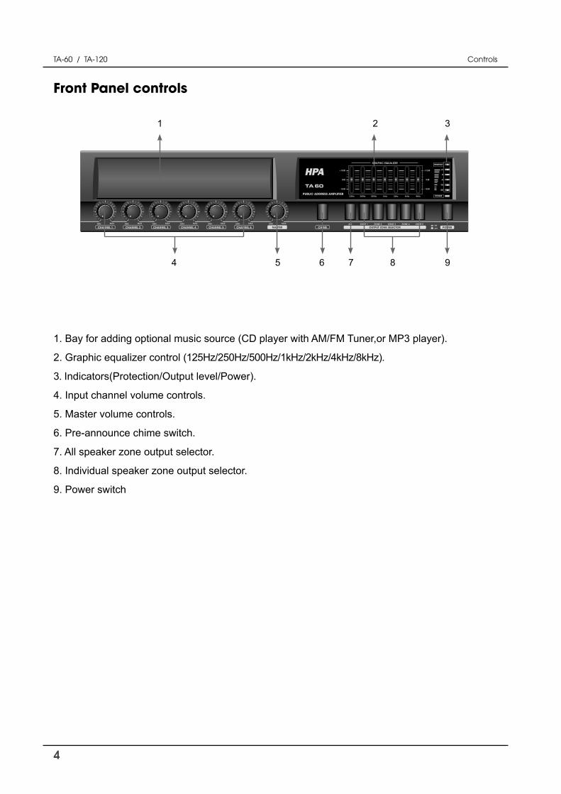
Front Panel controls
1 2 3
4 5 6 7 8
Controls
9
1. Bay for adding optional music source (CD player with AM/FM Tuner,or MP3 player).
2. Graphic equalizer control (125Hz/250Hz/500Hz/1kHz/2kHz/4kHz/8kHz).
3. Indicators(Protection/Output level/Power).
4. Input channel volume controls.
5. Master volume controls.
6. Pre-announce chime switch.
7. All speaker zone output selector.
8. Individual speaker zone output selector.
9. Power switch
5
TA-60 / TA-120
1 2 3 4 5 6
11 10 9 8
Controls
7
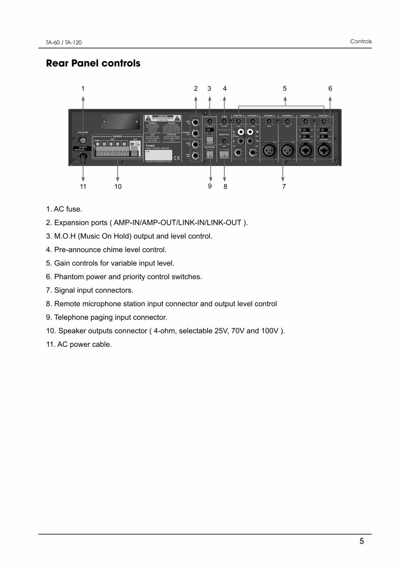
1. AC fuse.
2. Expansion ports ( AMP-IN/AMP-OUT/LINK-IN/LINK-OUT ).
3. M.O.H (Music On Hold) output and level control.
4. Pre-announce chime level control.
5. Gain controls for variable input level.
6. Phantom power and priority control switches.
7. Signal input connectors.
8. Remote microphone station input connector and output level control
9. Telephone paging input connector.
10. Speaker outputs connector ( 4-ohm, selectable 25V, 70V and 100V ).
11. AC power cable.
Rear Panel controls

6
TA-60 / TA-120
Installation:
CAUTION: Before you begin, make sure your mixer-amplifi er is disconnected from the power
source, with the power switch in the “OFF” position and all level controls turned completely down
(counterclockwise)
You may stack mixer-amplifi ers without using a cabinet or you may place a single mixer-amplifi er
on a surface with 12-inches (about 30cm) of air space around the unit for convection cooling.
When using an equipment rack, do not mount units directly on top of each other. Allow 2U be-
tween units for convection cooling. The side walls of the rack should be a minimum of 2-inches
(about 5cm) away from the amplifi er sides, and the back of the rack should be a minimum of
4-inches (about 10cm) from the mixer-amplifi er rear panel.
How to attach rack ears
1. Locate the two rack ears and six rack-ear screws supplied.
2. Place a rack-ear fl ush with the right front of the chassis.
3. Insert a screw into the bottom hole of the rack-ear and chassis. Screw it in.
4. Insert a screw into the rnid hole of the rack-ear and chassis. Screw it in
5. Insert a screw into the top hole of the rack-ear and chassis. Screw it in.
6. Repeat steps 2 to 5 for the left side of the chassis.
7. Remove the four legs from bottom of unit.
8. Please refer to Figure .
Setups
Setup
SuppliedScrews
SuppliedScrews
SuppliedScrews
[ How to connect rack ears ]

7
TA-60 / TA-120
Wiring guide
HPA recommends using pre-built or professionally wired balanced line,22 to 24 gauge cables.
Figure shows connector pin assignments for wiring .The RCA input connections can also be
used for unbalanced inputs.
Setups
-
+
BALANCED LINE
Unbalances 1/4” Connector Balances TRS 1/4” Connector
-
+s
-
+
BALANCED LINE
-
+s
+
UNBALANCED LINE
XLR Balanced Wiring Guide
Input output
-
+s
+
UNBALANCED LINE
-
+s
Choose input wire and connectors
For unbalanced use pin 1 and 3 have to be bridged

8
TA-60 / TA-120
For the amplifi er output connectors,HPA recommends using pre-built or professionally wired, high-quality, and heavy gauge speaker wires.You may use EURO blocks for your output connec-tors.To prevent the possibility of short-circuits, wrap or otherwise insulate exposed loudspeaker cable connectors.
Using the guidelines below, select the appropriate size wire based on the distance from amplifi er to speaker. The wire sizes apply to the 4-ohm tap.
Distance Wire Size
Up to 25 ft. 16 AWG
26~40 ft. 14 AWG
41~60 ft. 12 AWG
61~100 ft. 10 AWG
101~150 ft. 8 AWG
151~200 ft. 6 AWG
NOTE: Custom wiring shoule only be performed by qualifi ed personnel. Class 2 wiring is re-quired.
CAUTION: Never use shielded cable for output power wiring
Figure shows connector pin assignments for wiring
Setups
Choose output wire and connectors
-
-
+
+
-
+
-
+
-
+
-
+-
+-
+-
+-
+
-
+
-
+
High-Z Speaker Output
[ Pin assignments for speaker connecting ]

9
TA-60 / TA-120
Connections
Setups
INPUT: Connect microphones or balanced line-level sources to mixer-amplifi er balanced inputs.
Set Gain volume accordingly. Connect unbalanced line-level signals to RCA input connectors.
OUTPUT: Maintain proper polarity on output connectors.
For each output channel, connect the output EURO block terminals to the loudspeaker Ioads.
Use terminals marked (GND) and for a 4-ohm loudspeaker load, or use terminals marked
to and COM for constand-voltage loudspeaker loads.
Connect the COM terminal to speaker negative(-) lead; connect one of the other terminals to
speaker positive (+) lead.
The impedance and output voltage are same as following Table.
TA-60 4Ω / 15.5V 10Ω / 25V 83Ω / 70V 165Ω / 100VTA-120 4Ω / 22V 5.2Ω / 25V 42Ω / 70V 83Ω / 100V
[ output voltage and impedance]
NOTE : Impedances indicated in the table represent the total speaker system impedances.
Figure shows the way how to select impedance.
1 5
4Ω
[ How to change high impedance output voltage ]
The wires of output transformer are connected to terminal on output select pcb same as follow
table.
T10 T11 T12 T13100V RED wire BLUE wire GREEN wire BLACK wire70V GREEN wire RED wire BLUE wire BLACK wire25V BLUE wire GREEN wire RED wire BLACK wire
NOTE:These connectors are set in 100V output except US, CANADA ( 70V output )

10
TA-60 / TA-120
CAUTION : Never use both the Low-Z(4 ohms)and Hi-Z(25V, 70V and 100V) terminals at the
same time
[ Wrong connection ]
Setups
Speaker connection is shown in Figure.
Matchingtransformer
8Ω 8Ω
4Ω
[ How to connect speakers ]

11
TA-60 / TA-120 Setups
Typical input and output wiring is shown in Figure.

12
TA-60 / TA-120 Operations
Operations
External equipments connection
By connecting a signal processor such as an equalizer or limiter between the mixer section (PR E-AMP OUT) and the power amplifi er section(AMP IN) of the TA series, signals can be tailored for desired sound output.
NOTE
Inserting a 1/4-inch phone plug into AMP IN terminal disconnects internal power amplifi er section from the mixer section.
Expansion TA series
TA series mixer-amplifi er allows expansion with LINK IN and LINK OUT connector.If you need more input and output, just this function allows you can do that.This function affect which signals are heard when another mixer or TA series mixer-amplifi er are wired to the mixer-amplifi er.
[ Expansion TA series ]
[ External equipments connection ]

13
TA-60 / TA-120 Operations
TA series mixer-amplifi er supply user selectable 4 kinds of preannounce chime.
The way of set up is same as follow fi gure .
Preannounce chime
Figure shows default set in factory. You can move the position of jumper on the T3 of main PCB
for changing pre-announce chime.
Priority
This function allows talk over for MIC channel 1 and 2.
All other input signals are muted when this function is activated
during stay “ON” position.
Figure shows the priority switches and its “ON” and “OFF” posi-
tions.
Phantom power
TA series mixer-amplifi er supply DC + 15 Volts phantom power to
use condenser microphone with MIC 1 and 2 channels.
Figure shows the phantom power switches and its “ON” and
“OFF” positions.
[ Chime selection ]
[ Phantom and Priority ]

14
TA-60 / TA-120
Music On Hold
Connect mixer-amplifi er MUSIC ON HOLD connector to music-on-hold input on telephone inter-
face/PBX like telephone pager. Set MUSIC ON HOLD volume to proper level.
TA series mixer-amplifi er supply two way of MUSIC ON HOLD function.
When MUSIC ON HOLD slide switch is “INT” position, MUSIC ON HOLD output is routed from
option CDP or MP3 module internally.
When the slide switch is “EXT” position, MUSIC ON HOLD output is routed from LINE IN chan-
nel ( only channel 6 ) connected external music source.
Signal input gain control
TA series mixer-amplifi er can accept variable and wide range input signal with trim pot.
Adjusts the trim pot in a range of 44dB to accept variabe external equipments.
Figure 3.6 shows detail input sensitivities.
Priority Control
TA series mixer-amplifi er has three layer priority mute function. When higher level source is acti-
vated, other input signals are muted except same priority level source.
CH3~CH6>CH1~CH2, Remote MIC, Chime>Telephone paging.
Operations
[ Music on hold ]
[ Acceptable input sensitivity per each channels ]
15
TA-60 / TA-120 Applications
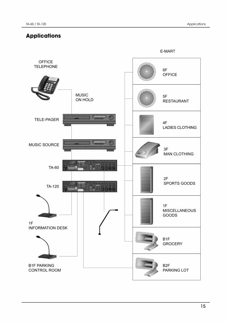
Applications
4FLADIES CLOTHING
3FMAN CLOTHING
2FSPORTS GOODS
1FMISCELLANEOUSGOODS
B1FGROCERY
B2FPARKING LOT
1FINFORMATION DESK
TELE-PAGER
E-MART
MUSICON HOLD
OFFICETELEPHONE
MUSIC SOURCE
TA-60
TA-120
B1F PARKINGCONTROL ROOM
5FRESTAURANT
6FOFFICE

16
TA-60 / TA-120 Block diagrams
Block diagrams

17
TA-60 / TA-120 Specifi cations
Specifi cations
TA-60 TA-120
Input Sensitivity for full output at maxi-mum gain
Balanced Microphone Channels -50dB ± 3dB
Balanced Line Channels -22dB ± 3dB
Balanced Remote Microphone Station -50dB ± 3dB
Balanced Telephone Paging -21dB ± 3dB
Unbalanced Link-In -17dB ± 3dB
Unbalanced Amp-In 0dB ± 3dB
Frequency Response at 1 watt from speaker out tap.100Hz~10kHz +1.5dB / -3dB
Graphic Equalizer
125Hz,250Hz,500Hz,1kHz,2kHz,4kHz,8kHz ±12dB ±3dB
Signal to Noise Ratio at rated power output Better than 90dB
Crosstalk at all control maximum -70dB at 1kHz
Rated Output Power at THD 0.5% 60Watts 120Watts
Total Harmonic Distortion(THD) at 1kHz rated power Less than 0.5%
Phantom Power 15VDC
Power Band Width at 1kHz from speaker out tap 80Hz~15kHz with less than 0.5% THD
DC Output Offset Less than ±3mV
Operating Temperature/Humidity at non-con-densing 0°~40°C at 95% humidity
Output Voltage and Impedance
4Ω 15.5V 22V
25V 10Ω 5.2Ω
70V 83Ω 42Ω
100V 165Ω 83Ω
Construction
Cooling Convection Cooled
Dimensions (Width/Height/Depth) 420(W) x 88(H) x 320(D) mm
Net Weight 8.72 kg 9.76 kg
Necessary modifi cations are carried out without notice
Performance