
5008: Computer Architecturetwins.ee.nctu.edu.tw/courses/ca_08/lecture/Lecture_03... ·...
68
CA Lecture03 - pipelining ([email protected]) 03-1 5008: Computer Architecture 5008: Computer 5008: Computer Architecture Architecture Appendix A Appendix A – – Pipelining Pipelining
Transcript of 5008: Computer Architecturetwins.ee.nctu.edu.tw/courses/ca_08/lecture/Lecture_03... ·...

CA Lecture03 - pipelining ([email protected]) 03-1
5008: Computer Architecture
5008: Computer 5008: Computer ArchitectureArchitecture
Appendix A Appendix A –– PipeliningPipelining

CA Lecture03 - pipelining ([email protected]) 03-2
Why Pipeline? Because the resources are there!
Instr.
Order
Time (clock cycles)
Inst 0
Inst 1
Inst 2
Inst 4
Inst 3A
LUIm Reg Dm Reg
AL
UIm Reg Dm Reg
AL
UIm Reg Dm Reg
AL
UIm Reg Dm Reg
AL
UIm Reg Dm Reg
Single cycle data path

CA Lecture03 - pipelining ([email protected]) 03-3
Pipeline Review• A pipeline is like an hooked assembly line.• Pipelining, in general, is not visible to the programmer (vs ILP)• Pipelining doesn’t help latency of single task, it helps
throughput of entire workload• Pipeline rate limited by slowest pipeline stage• Multiple tasks operating simultaneously using different
resources• Potential speedup = Number pipe stages, if perfectly balanced
stage.• Unbalanced lengths of pipe stages reduces speedup• Time to “fill” pipeline and time to “drain” it reduces speedup• Stall for Dependences

CA Lecture03 - pipelining ([email protected]) 03-4
Outline• MIPS – An ISA example for
pipelining• 5 stage pipelining• Structural and Data Hazards• Forwarding• Branch Schemes• Exceptions and Interrupts• Conclusion

CA Lecture03 - pipelining ([email protected]) 03-5
A "Typical" RISC ISA• 32-bit fixed format instruction (3 formats)• 32 32-bit GPR (R0 contains zero, DP take pair)• 3-address, reg-reg arithmetic instruction• Single address mode for load/store:
base + displacement– no indirection
• Simple branch conditions• Delayed branch
see: SPARC, MIPS, HP PA-Risc, DEC Alpha, IBM PowerPC,CDC 6600, CDC 7600, Cray-1, Cray-2, Cray-3

CA Lecture03 - pipelining ([email protected]) 03-6
Example: MIPS (- MIPS)
Op31 26 01516202125
Rs1 Rd immediate
Op31 26 025
Op31 26 01516202125
Rs1 Rs2
target
Rd Opx
Register-Register561011
Register-Immediate
Op31 26 01516202125
Rs1 Rs2/Opx immediate
Branch
Jump / Call

CA Lecture03 - pipelining ([email protected]) 03-7
Datapath vs Control
• Datapath: Storage, FU, interconnect sufficient to perform the desired functions– Inputs are Control Points– Outputs are signals
• Controller: State machine to orchestrate operation on the data path– Based on desired function and signals
Datapath Controller
Control Points
signals

CA Lecture03 - pipelining ([email protected]) 03-8
Approaching an ISA• Instruction Set Architecture
– Defines set of operations, instruction format, hardware supported data types, named storage, addressing modes, sequencing
• Meaning of each instruction is described by RTL on architected registers and memory
• Given technology constraints assemble adequate datapath– Architected storage mapped to actual storage– Function units to do all the required operations– Possible additional storage (eg. MAR, MBR, …)– Interconnect to move information among regs and FUs
• Map each instruction to sequence of RTLs• Collate sequences into symbolic controller state transition
diagram (STD)• Lower symbolic STD to control points• Implement controller

CA Lecture03 - pipelining ([email protected]) 03-9
Outline• MIPS – An ISA example for
pipelining -- Read Appendix B• 5 stage pipelining• Structural and Data Hazards• Forwarding• Branch Schemes• Exceptions and Interrupts• Conclusion

CA Lecture03 - pipelining ([email protected]) 03-10
The Five Steps of the Load Instruction
• Every instruction can be implemented in at most 5 clock cycle• Ifetch: Instruction Fetch
– Fetch the instruction from the Instruction Memory• Reg/Dec: Registers Fetch and Instruction Decode• Exec: Execution and calculate the memory address• Mem: Read the data from the Data Memory• Wr: Write the data back to the register file
Cycle 1 Cycle 2 Cycle 3 Cycle 4 Cycle 5
Ifetch Reg/Dec Exec Mem WrLoad
Branch requires ? cycles, Store requires ? cycles, others require ? cycles

CA Lecture03 - pipelining ([email protected]) 03-11
The Four Steps of R-type Instruction
• Ifetch: Instruction Fetch– Fetch the instruction from the Instruction Memory– Update PC
• Reg/Dec: Registers Fetch and Instruction Decode• Exec:
– ALU operates on the two register operands• Wr: Write the ALU output back to the register file
Cycle 1 Cycle 2 Cycle 3 Cycle 4
Ifetch Reg/Dec Exec WrR-type
does not access data memory…

CA Lecture03 - pipelining ([email protected]) 03-12
Important Observation• Each functional unit can only be used once per instruction• Each functional unit must be used at the same step for all
instructions:– Load uses Register File’s Write Port during its 5th step
– R-type uses Register File’s Write Port during its 4th step
Ifetch Reg/Dec Exec Mem WrLoad1 2 3 4 5
Ifetch Reg/Dec Exec WrR-type1 2 3 4
This’s what caused the problem
Structural hazard !!

CA Lecture03 - pipelining ([email protected]) 03-13
Pipelining the R-type and Load Instruction
• We have pipeline conflict or structural hazard:– Two instructions try to write to the register file at the
same time!– Only one write port
Clock
Cycle 1 Cycle 2 Cycle 3 Cycle 4 Cycle 5 Cycle 6 Cycle 7 Cycle 8 Cycle 9
Ifetch Reg/Dec Exec WrR-type
Ifetch Reg/Dec Exec WrR-type
Ifetch Reg/Dec Exec Mem WrLoad
Ifetch Reg/Dec Exec WrR-type
Ifetch Reg/Dec Exec WrR-type
Ops! We have a problem!

CA Lecture03 - pipelining ([email protected]) 03-14
Sol 1: Insert “Bubble” into the Pipeline
• Insert a “bubble” into the pipeline to prevent 2 writes at the same cycle– The control logic can be complex.– Lose instruction fetch and issue opportunity.
• No instruction is started in Cycle 6!
Clock
Cycle 1 Cycle 2 Cycle 3 Cycle 4 Cycle 5 Cycle 6 Cycle 7 Cycle 8 Cycle 9
Ifetch Reg/Dec Exec WrR-type
Ifetch Reg/Dec Exec
Ifetch Reg/Dec Exec Mem WrLoad
Ifetch Reg/Dec Exec WrR-type
Ifetch Reg/Dec Exec WrR-type Pipeline
Bubble
Ifetch Reg/Dec Exec WrR-type

CA Lecture03 - pipelining ([email protected]) 03-15
Sol 2: Delay R-type’s Write by One Cycle• Now R-type instructions also use Reg File’s write port at Step 5• Mem step for R-type inst. is a NOOP : nothing is being done.
Clock
Cycle 1 Cycle 2 Cycle 3 Cycle 4 Cycle 5 Cycle 6 Cycle 7 Cycle 8 Cycle 9
Ifetch Reg/Dec Mem WrR-type
Ifetch Reg/Dec Mem WrR-type
Ifetch Reg/Dec Exec Mem WrLoad
Ifetch Reg/Dec Mem WrR-type
Ifetch Reg/Dec Mem WrR-type
Ifetch Reg/Dec Exec WrR-type Mem
Exec
Exec
Exec
Exec
1 2 3 4 5

Similarly, the Four Steps of Store
• Ifetch: Instruction Fetch– Fetch the instruction from the Instruction Memory– Update PC
• Reg/Dec: Registers Fetch and Instruction Decode• Exec: Calculate the memory address• Mem: Write the data into the Data Memory
Cycle 1 Cycle 2 Cycle 3 Cycle 4
Ifetch Reg/Dec Exec MemStore Wr
In order to keep our pipeline uniform

The Three Steps of Beq
• Ifetch: Instruction Fetch– Fetch the instruction from the Instruction Memory
• Reg/Dec: – Registers Fetch and Instruction Decode
• Exec: – compares the two register operand, – select correct branch target address– latch into PC
Cycle 1 Cycle 2 Cycle 3 Cycle 4
Ifetch Reg/Dec Exec MemBeq Wr

CA Lecture03 - pipelining ([email protected]) 03-18
Designing a Pipelined Processor• Examine the datapath and control diagram
– Starting with single- or multi-cycle datapath?– Single- or multi-cycle control?
• Partition datapath into steps• Insert pipeline registers between
successive steps• Associate resources with steps• Ensure that flows do not conflict, or
figure out how to resolve• Assert control in appropriate stage

CA Lecture03 - pipelining ([email protected]) 03-19
5 Steps of MIPS DatapathMemoryAccess
WriteBack
InstructionFetch
Instr. DecodeReg. Fetch
ExecuteAddr. Calc
LMD
ALU
MU
X
Mem
ory
RegFile
MU
XM
UX
Data
Mem
ory
MU
X
SignExtend
4
Adder Zero?
Next SEQ PC
Address
Next PC
WB Data
Inst
RD
RS1
RS2
ImmIR <= mem[PC];
PC <= PC + 4
Reg[IRrd] <= Reg[IRrs] opIRop Reg[IRrt]

CA Lecture03 - pipelining ([email protected]) 03-20
5 Steps of MIPS DatapathMemoryAccess
WriteBack
InstructionFetch
Instr. DecodeReg. Fetch
ExecuteAddr. Calc
ALU
Mem
ory
RegFile
MU
XM
UX
Data
Mem
ory
MU
X
SignExtend
Zero?
IF/ID
ID/EX
MEM
/WB
EX/M
EM4
Adder
Next SEQ PC Next SEQ PC
RD RD RD WB
Dat
a
Next PC
Address
RS1
RS2
Imm
MU
X
IR <= mem[PC];
PC <= PC + 4A <= Reg[IRrs];
B <= Reg[IRrt]
rslt <= A opIRop B
Reg[IRrd] <= WBWB <= rslt
Pipeline registers (latches)

CA Lecture03 - pipelining ([email protected]) 03-21
Inst. Set Processor ControllerIR <= mem[PC];
PC <= PC + 4
A <= Reg[IRrs];
B <= Reg[IRrt]
r <= A opIRop B
Reg[IRrd] <= WB
WB <= r
Ifetch
opFetch-DCD
PC <= IRjaddrif bop(A,b)
PC <= PC+IRim
br jmpRR
r <= A opIRop IRim
Reg[IRrd] <= WB
WB <= r
RIr <= A + IRim
WB <= Mem[r]
Reg[IRrd] <= WB
LD
STJSR JR
• Use data stationary control– local decode for each instruction phase / pipeline stage

• Pass control signals along just like the data– Main control generates control signals during ID
Data Stationary Control
Control
EX
M
WB
M
WB
WB
IF/ID ID/EX EX/MEM MEM/WB
Instruction

Use of “Data Stationary Control”
• The Main Control generates the control signals during Reg/Dec– Control signals for Exec (ExtOp, ALUSrc, ...) are used 1 cycle later– Control signals for Mem (MemWr Branch) are used 2 cycles later– Control signals for Wr (MemtoReg MemWr) are used 3 cycles later
IF/ID R
egister
ID/E
x Register
Ex/M
emR
egister
Mem
/Wr
Register
Reg/Dec Exec Mem
ExtOp
ALUOpRegDst
ALUSrc
BranchMemWr
MemtoRegRegWr
MainControl
ExtOp
ALUOpRegDst
ALUSrc
MemtoRegRegWr
MemtoRegRegWr
MemtoRegRegWr
Branch
MemWr
BranchMemWr
Wr

CA Lecture03 - pipelining ([email protected]) 03-24
Visualizing PipeliningFigure A.2, Page A-8
Instr.
Order
Time (clock cycles)
Reg ALU DMemIfetch Reg
Reg ALU DMemIfetch Reg
Reg ALU DMemIfetch Reg
Reg ALU DMemIfetch Reg
Cycle 1 Cycle 2 Cycle 3 Cycle 4 Cycle 6 Cycle 7Cycle 5

CA Lecture03 - pipelining ([email protected]) 03-25
Outline• MIPS – An ISA example for
pipelining• 5 stage pipelining• Structural and Data Hazards• Forwarding• Branch Schemes• Exceptions and Interrupts• Conclusion

CA Lecture03 - pipelining ([email protected]) 03-26
Pipelining is not quite that easy!• Limits to pipelining: Hazards prevent next
instruction from executing during its designated clock cycle– Structural hazards: HW cannot support this combination
of instructions (single person to fold and put clothes away)
– Data hazards: Instruction depends on result of prior instruction still in the pipeline (missing sock)
– Control hazards: Caused by delay between the fetching of instructions and decisions about changes in control flow (branches and jumps).

CA Lecture03 - pipelining ([email protected]) 03-27
One Memory Port/Structural Hazards
Detection is easy in this case! (right half highlight means read, left half write)
Time (clock cycles)
Instr.
Order
Load
Instr 1
Instr 2
Instr 3
Instr 4
Reg ALU DMemIfetch Reg
Reg ALU DMemIfetch Reg
Reg ALU DMemIfetch Reg
Reg ALU DMemIfetch Reg
Cycle 1 Cycle 2 Cycle 3 Cycle 4 Cycle 6 Cycle 7Cycle 5
Reg ALU DMemIfetch Reg

CA Lecture03 - pipelining ([email protected]) 03-28
Structural Hazards Limit Performance
• Why? The primary reason is to reduce cost of the unit
• Example: if 1.3 memory accesses per instruction and only one memory access per cycle then– average CPI = 1.3– otherwise resource is more than 100% utilized
• Solution 1: Use separate instruction and data memories
• Solution 2: Allow memory to read and write more than one word per cycle
• Solution 3: Stall

CA Lecture03 - pipelining ([email protected]) 03-29
Speed Up Equations for Pipelining
pipelined
dunpipeline
Time CycleTime Cycle
CPI stall Pipeline CPI Ideal
depth Pipeline CPI Ideal Speedup ×+×
=
pipelined
dunpipeline
Time CycleTime Cycle
CPI stall Pipeline 1
depth Pipeline Speedup ×+
=
Instper cycles Stall Average CPI Ideal CPIpipelined +=
For simple RISC pipeline, CPI = 1:
de pipelineClock cyclnede unpipeliClock cycl
CPICPI
inedtime pipelstruction Average inelinedtime unpipstruction Average inSpeedup
pipelined
dunpipeline ×==
for balanced pipelining

CA Lecture03 - pipelining ([email protected]) 03-30
Example: One or Two Memory Ports?• Machine A: Dual ported memory (“Harvard Architecture”)• Machine B: Single ported memory, but its pipelined
implementation has a 1.05 times faster clock rate• Ideal CPI = 1 for both• Loads are 40% of instructions executed
SpeedUpA = Pipeline Depth/(1 + 0) x (clockunpipe/clockpipe)= Pipeline Depth
SpeedUpB = Pipeline Depth/(1 + 0.4 x 1) x (clockunpipe/(clockunpipe / 1.05)= (Pipeline Depth/1.4) x 1.05= 0.75 x Pipeline Depth
SpeedUpA / SpeedUpB = Pipeline Depth/(0.75 x Pipeline Depth) = 1.33
• Machine A is 1.33 times faster

CA Lecture03 - pipelining ([email protected]) 03-31
One Memory Port Structural Hazards
Instr.
Order
Time (clock cycles)
Load
Instr 1
Instr 2
Stall
Instr 3
Reg ALU DMemIfetch Reg
Reg ALU DMemIfetch Reg
Reg ALU DMemIfetch Reg
Cycle 1 Cycle 2 Cycle 3 Cycle 4 Cycle 6 Cycle 7Cycle 5
Reg ALU DMemIfetch Reg
Bubble Bubble Bubble BubbleBubble
How do you “bubble” the pipe?

CA Lecture03 - pipelining ([email protected]) 03-32
Handling Stalls• How to stall?
– Stall instruction in IF and ID: not change PC and IF/ID=> the stages re-execute the instructions
– What to move into EX: insert an NOP by changing EX, MEM, WB control fields of ID/EX pipeline register to 0
• as control signals propagate, all control signals to EX, MEM, WB are de-asserted and no registers or memories are written

CA Lecture03 - pipelining ([email protected]) 03-33
Data Hazard Problem
add r1 ,r2,r3
sub r4, r1 ,r3
and r6, r1 ,r7
or r8, r1 ,r9
xor r10, r1 ,r11
• Due to the overlapped instructions.
Example: r1 cannot be read by other instructions before it is written by the add.

CA Lecture03 - pipelining ([email protected]) 03-34
Instr.
Order
add r1,r2,r3
sub r4,r1,r3
and r6,r1,r7
or r8,r1,r9
xor r10,r1,r11
Reg ALU DMemIfetch Reg
Reg ALU DMemIfetch Reg
Reg ALU DMemIfetch Reg
Reg ALU DMemIfetch Reg
Reg ALU DMemIfetch Reg
RAW Hazards on R1Time (clock cycles)
IF ID/RF EX MEM WB
Dependencies backwards in time are hazards

CA Lecture03 - pipelining ([email protected]) 03-35
Types of Data HazardsThree types: (inst. i1 followed by inst. i2)• RAW (read after write): dependence
i2 tries to read operand before i1 writes it• WAR (write after read): anti-dependence
i2 tries to write operand before i1 reads it– Gets wrong operand, e.g., auto-increment addr.– Can’t happen in MIPS 5-stage pipeline because:
• All instructions take 5 stages, and reads are always in stage 2, and writes are always in stage 5
• WAW (write after write): output dependencei2 tries to write operand before i1 writes it– Leaves wrong result ( i1’s not i2’s); occur only in pipelines that
write in more than one stage– Can’t happen in MIPS 5-stage pipeline because:
• All instructions take 5 stages, and writes are always in stage 5– Out of order executions may suffer this data dependence

CA Lecture03 - pipelining ([email protected]) 03-36
• Write After Read (WAR)InstrJ writes operand before InstrI reads it
• Called an “anti-dependence” by compiler writers.This results from reuse of the name “r1”.
• Can’t happen in MIPS 5 stage pipeline because:• Can happen in between a shorter (Int) pipeline and a longer (FP)
pipeline• WAR hazards can happen if instructions execute out of order
or access data late
I: sub r4,r1,r3 J: add r1,r2,r3K: mul r6,r1,r7
WAR Data Hazard

CA Lecture03 - pipelining ([email protected]) 03-37
Instr.
Order
add r4,r1,r3
sub r1,r2,r3 Reg ALU DMemIfetch Reg
Reg ALU DMemIfetch Reg
No WAR Hazards on r1Time (clock cycles)
IF ID/RF EX MEM WBread
writeread
write

CA Lecture03 - pipelining ([email protected]) 03-38
WAW Data Hazard
Write After Write (WAW)InstrJ writes operand before InstrI writes it.
• Called an “output dependence” by compiler writersThis also results from the reuse of name “r1”.
• Can’t happen in 5 stage pipeline because: – All instructions take 5 stages, and – Writes are always in stage 5
• Will see WAR and WAW in more complicated pipes
I: sub r1,r4,r3 J: add r1,r2,r3K: mul r6,r1,r7

CA Lecture03 - pipelining ([email protected]) 03-39
Instr.
Order
add r1,r4,r3
sub r1,r2,r3 Reg ALU DMemIfetch Reg
Reg ALU DMemIfetch Reg
No WAW Hazards on R1Time (clock cycles)
IF ID/RF EX MEM WBwrite
write

CA Lecture03 - pipelining ([email protected]) 03-40
Data Forwarding to Avoid Data Hazard• With data forwarding (also called bypassing or short-
circuiting), data is transferred back to earlier pipeline stages before it is written into the register file.
– Instr i: add r1,r2,r3 (result ready after EX stage)----------------------
– Instr j: sub r4,r1,r5 (result needed in EX stage)
• This either eliminates or reduces the penalty of RAW hazards.
• To support data forwarding, additional hardware is required. – Multiplexors to allow data to be transferred back– Control logic for the multiplexors

CA Lecture03 - pipelining ([email protected]) 03-41
Data Hazard Solution“Forward” result from one stage to another
“or” OK if define read/write properly
Instr.
Order
Time (clock cycles)
add r1,r2,r3
sub r4,r1,r3
and r6,r1,r7
or r8,r1,r9
xor r10,r1,r11
IF ID/RF EX MEM WBAL
UIm Reg Dm Reg
AL
UIm Reg Dm Reg
AL
UIm Reg Dm Reg
Im
AL
UReg Dm Reg
AL
UIm Reg Dm Reg

CA Lecture03 - pipelining ([email protected]) 03-42
HW Change for Forwarding
MEM
/WR
ID/EX
EX/M
EM
DataMemory
ALU
mux
mux
Registers
NextPC
Immediate
mux

CA Lecture03 - pipelining ([email protected]) 03-43
Time (clock cycles)
Instr.
Order
lw r1, 0(r2)
sub r4,r1,r6
and r6,r1,r7
or r8,r1,r9
Data Hazard Even with Forwarding
Reg ALU DMemIfetch Reg
Reg ALU DMemIfetch Reg
Reg ALU DMemIfetch Reg
Reg ALU DMemIfetch Reg
Can’t solve with forwarding
Must delay/stall instruction dependent on loads

CA Lecture03 - pipelining ([email protected]) 03-44
Pipeline Interlock Solution for Load Stall
Time (clock cycles)
or r8,r1,r9
Instr.
Order
lw r1, 0(r2)
sub r4,r1,r6
and r6,r1,r7
Reg ALU DMemIfetch Reg
RegIfetch ALU DMem RegBubble
Ifetch ALU DMem RegBubble Reg
Ifetch
ALU DMemBubble Reg
Pipeline interlockHow is this detected?

CA Lecture03 - pipelining ([email protected]) 03-45
Try producing fast code fora = b + c;d = e – f;
assuming a, b, c, d ,e, and f in memory. Slow code:
LW Rb,bLW Rc,cADD Ra,Rb,RcSW a,RaLW Re,e LW Rf,fSUB Rd,Re,RfSW d,Rd
Software Scheduling to Avoid Load Hazards
Fast code:LW Rb,bLW Rc,cLW Re,e ADD Ra,Rb,RcLW Rf,fSW a,RaSUB Rd,Re,RfSW d,Rd
Compiler optimizes for performance. Hardware checks for safety.

CA Lecture03 - pipelining ([email protected]) 03-46
Compiler Avoiding Load Stalls
% loads stalling pipeline
0% 20% 40% 60% 80%
tex
spice
gcc
25%
14%
31%
65%
42%
54%
scheduled unscheduled
Compilers reduce the number of load stalls, but do not completely eliminate them.

CA Lecture03 - pipelining ([email protected]) 03-47
Outline• MIPS – An ISA example for
pipelining• 5 stage pipelining• Structural and Data Hazards• Forwarding• Branch Schemes• Exceptions and Interrupts• Conclusion

CA Lecture03 - pipelining ([email protected]) 03-48
Control Hazard on BranchesThree Stages Stall
10: beq r1,r3,36
14: and r2,r3,r5
18: or r6,r1,r7
22: add r8,r1,r9
36: xor r10,r1,r11
Reg ALU DMemIfetch Reg
Reg ALU DMemIfetch Reg
Reg ALU DMemIfetch Reg
Reg ALU DMemIfetch Reg
Reg ALU DMemIfetch Reg
What do you do with the 3 instructions in between?

CA Lecture03 - pipelining ([email protected]) 03-49
Control/Branch Hazards• Control hazards, which occur due to instructions changing
the PC, can result in a large performance loss.• A branch is either
– Taken: PC <= PC + 4 + Imm ; branch target address– Not Taken: PC <= PC + 4
• The simplest solution is to stall the pipeline as soon as a branch instruction is detected.– Detect the branch in the ID stage– Don’t know if the branch is taken until the EX stage– If the branch is taken, we need to repeat the IF and ID stages– New PC is not changed until the end of the MEM stage, after
determining if the branch is taken and the new PC value

CA Lecture03 - pipelining ([email protected]) 03-50
Branch Stall Impact• If CPI = 1, 30% branch,
Stall 3 cycles => new CPI = 1.9 !!• Two part solution:
– Determine branch taken or not sooner, AND– Compute taken branch address earlier
• MIPS branch tests if register = 0 or ≠ 0• MIPS Solution:
– Move Zero test to ID/RF stage– Adder to calculate new PC in ID/RF stage– 1 clock cycle penalty for branch versus 3

CA Lecture03 - pipelining ([email protected]) 03-51
Adder
IF/ID
Pipelined MIPS DatapathMemoryAccess
WriteBack
InstructionFetch
Instr. DecodeReg. Fetch
ExecuteAddr. Calc
ALU
Mem
ory
RegFile
MU
X
Data
Mem
ory
MU
X
SignExtend
Zero?
MEM
/WB
EX/M
EM4
Adder
Next SEQ PC
RD RD RD WB
Dat
a
• Interplay of instruction set design and cycle time.
Next PC
Address
RS1
RS2
Imm
MU
X
ID/EX
page A-38
CA Lecture03 - pipelining ([email protected]) 03-52
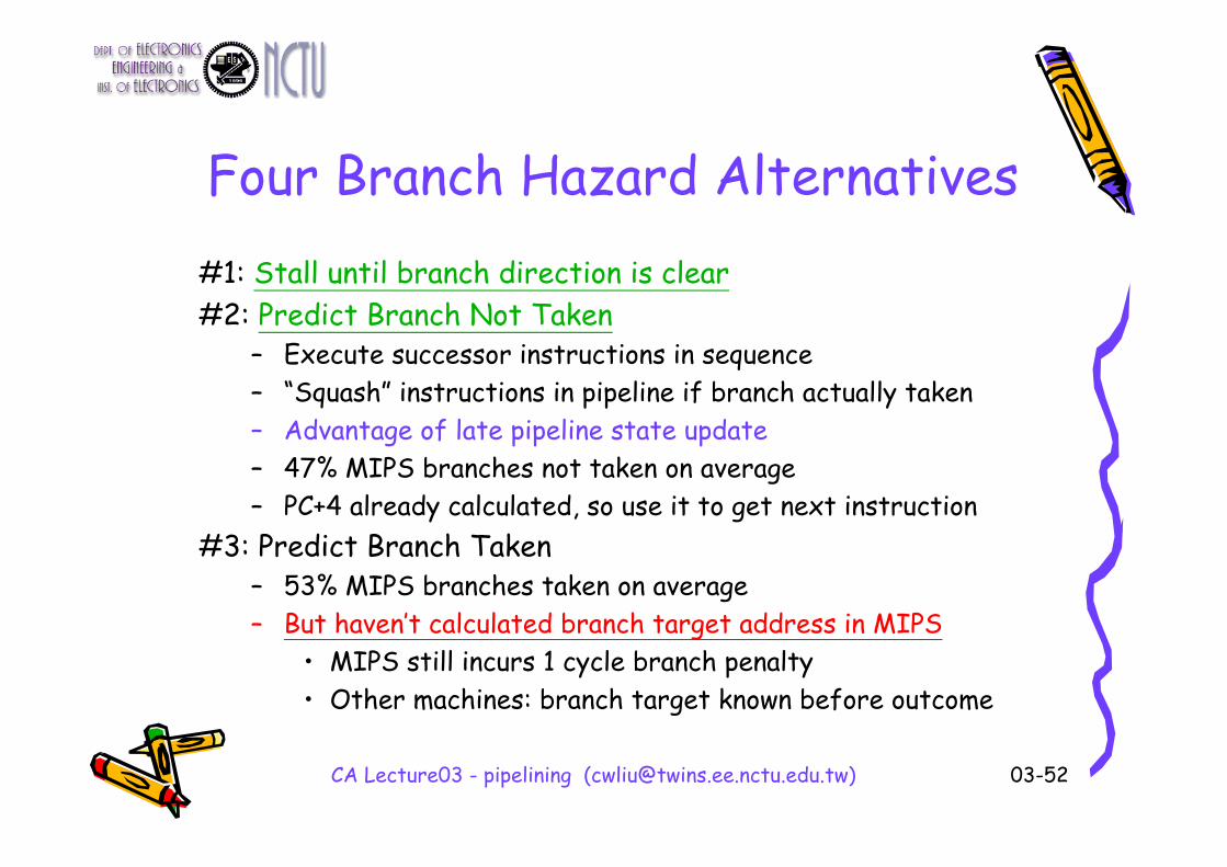
Four Branch Hazard Alternatives#1: Stall until branch direction is clear#2: Predict Branch Not Taken
– Execute successor instructions in sequence– “Squash” instructions in pipeline if branch actually taken– Advantage of late pipeline state update– 47% MIPS branches not taken on average– PC+4 already calculated, so use it to get next instruction
#3: Predict Branch Taken– 53% MIPS branches taken on average– But haven’t calculated branch target address in MIPS
• MIPS still incurs 1 cycle branch penalty• Other machines: branch target known before outcome

CA Lecture03 - pipelining ([email protected]) 03-53
Four Branch Hazard Alternatives
#4: Delayed Branch -- make the stall cycle useful– Define branch to take place AFTER a following instruction
branch instructionsequential successor1sequential successor2........sequential successorn
branch target if taken
– 1 slot delay allows proper decision and branch target address in 5 stage pipeline
– MIPS uses this
e.g. Branch delay slot of length nThese insts. are executed !!

CA Lecture03 - pipelining ([email protected]) 03-54
Stall -- Control Hazard Solution• Stall: wait until decision is clear
– It’s possible to move up decision to 2nd stage by adding hardware to check registers as being read
• Impact: 2 cycles (or 1 cycle penalty) per branch instruction => slow
Instr.
Order
Time (clock cycles)
Add
Beq
Load
AL
UMem Reg Mem Reg
AL
UMem Reg Mem Reg
AL
UReg Mem RegMem

CA Lecture03 - pipelining ([email protected]) 03-55
Predict-- Control Hazard Solution• Predict: guess one direction then back up if wrong
– Predict not taken, for example
• Impact: 1 clock cycle per branch instruction if right, 2 if wrong
Instr.
Order
Time (clock cycles)
Add
Beq
Load
AL
UMem Reg Mem Reg
AL
UMem Reg Mem Reg
AL
UReg Mem RegMem

CA Lecture03 - pipelining ([email protected]) 03-56
Predict-Not-Taken Example
A Stall indeed
1 clock cycle per branch instruction if right, 2 if wrong

CA Lecture03 - pipelining ([email protected]) 03-57
Delayed Branch-- Control Hazard Solution
• Redefine branch behavior (takes place after next instruction) “delayed branch”
• Impact: 1 clock cycles per branch instruction if can find instruction to put in “slot”
Instr.
Order
Time (clock cycles)
Add
Beq
Misc
AL
UMem Reg Mem Reg
AL
UMem Reg Mem Reg
MemA
LUReg Mem Reg
Load Mem
AL
UReg Mem Reg

CA Lecture03 - pipelining ([email protected]) 03-58
Delayed Branch• Delayed branch make the stall cycle useful
– Add delay slots = branch penalty = length of branch delay
• 1 slot for 5-stage DLX/MIPS– Instructions in the delay slot are executed
whether or not the branch is taken– See if the compiler can schedule something
useful in these slots• When the slots cannot be scheduled, they are filled
with the no-op instruction (indeed, stall!!)– Hope that filled slots actually help advance the
computation

CA Lecture03 - pipelining ([email protected]) 03-59
Scheduling Branch Delay Slots
• A is the best choice, fills delay slot & reduces instruction count (IC)• In B, the sub instruction may need to be copied, increasing IC• In B and C, must be okay to execute sub when branch fails
add $1,$2,$3if $2=0 then
delay slot
A. From before branch B. From branch target C. From fall through
add $1,$2,$3if $1=0 thendelay slot
add $1,$2,$3if $1=0 then
delay slot
sub $4,$5,$6
sub $4,$5,$6
becomes becomes becomes
if $2=0 then
add $1,$2,$3add $1,$2,$3if $1=0 thensub $4,$5,$6
add $1,$2,$3if $1=0 then
sub $4,$5,$6

CA Lecture03 - pipelining ([email protected]) 03-60
Delay-Branch Scheduling Schemes and Their Requirements
When branch is not taken.
Must be OK to execute instructions if branch is taken
From fall through
When branch is taken. May enlarge programif instructions are duplicated
Must be OK to execute rescheduled instructions if branch is not taken. May need to duplicate instructions
From target
AlwaysBranch must not depend on the rescheduled instructions
From before
Improve Performance When?
RequirementsScheduling Strategy

CA Lecture03 - pipelining ([email protected]) 03-61
Delayed Branch Summary• Compiler effectiveness for single branch delay slot:
– Fills about 60% of branch delay slots– About 80% of instructions executed in branch delay slots
useful in computation– About 50% (60% x 80%) of slots usefully filled
• As processor go to deeper pipelines and multiple issue, the branch delay grows and need more than one delay slots– Delayed branching (the static way) has lost popularity
compared to more expensive but more flexible dynamic approaches
– Growth in available transistors has made dynamic approaches relatively cheaper

CA Lecture03 - pipelining ([email protected]) 03-62
Evaluating Branch Alternatives
• Assume 4% unconditional branch, 6% conditional branch-untaken, 10% conditional branch-taken
Branch Branch CPI speedup v. speedup v.scheme penalty unpipelined stall
Stall pipeline 3 1.60 3.1 1.0Predict taken 1 1.20 4.2 1.33Predict not taken 1 1.14 4.4 1.40Delayed branch 0.5 1.10 4.5 1.45
Pipeline speedup = Pipeline depth1 +Branch frequency ×Branch penalty

CA Lecture03 - pipelining ([email protected]) 03-63
Deeper Pipeline Example• For a deeper pipeline, e.g. MIPS R4K, it takes at least 3
pipeline stages before the branch-target address is known and an additional cycle before the branch condition is evaluated, assuming no stalls on the registers in the conditional comparisons– Assuming an ideal CPI of 1,
penaltyBranch frequency Branch branches from cycles stall Pipeline ×=
branches from cycles stall Pipeline 1
depth Pipeline Speedup+
=

CA Lecture03 - pipelining ([email protected]) 03-64
Branch Penalties
Branch Penalty Penalty Penaltyscheme unconditional. untaken taken
Flush pipeline 2 3 3Predict taken 2 3 2Predict not taken 2 0 3
Try to find the CPI penalties for 3 branch schemes (Fig. A.16)
• Assume 4% unconditional branch, 6% conditional branch-untaken, 10% conditional branch-taken
• Branch penalties

CA Lecture03 - pipelining ([email protected]) 03-65
Problems with Pipelining• Exception: An unusual event happens to an instruction during its
execution – Examples: divide by zero, undefined opcode
• Interrupt: Hardware signal to switch the processor to a new instruction stream
– Example: a sound card interrupts when it needs more audio outputsamples (an audio “click” happens if it is left waiting)
• Problem: It must appear that the exception or interrupt must appear between 2 instructions (Ii and Ii+1)
– The effect of all instructions up to and including Ii is totallingcomplete
– No effect of any instruction after Ii can take place • The interrupt (exception) handler either aborts program or
restarts at instruction Ii+1

CA Lecture03 - pipelining ([email protected]) 03-66
Exceptions in MIPS
NonWB
Page fault on data fetch; misaligned memory access; memory protection violation
MEMArithmetic exceptionEXUndefined or illegal opcodeID
Page fault on instruction fetch; misaligned memory access; memory protection violation
IFProblem exceptions occurringPipeline stage
Note: Multiple exceptions may occur in the same clock cyclein pipelining architecture

Precise Exceptions in Static Pipelines
Key observation: architected state only change in memory and register write stages.

CA Lecture03 - pipelining ([email protected]) 03-68
And In Conclusion: Control & Pipelining• Control VIA State Machines and Microprogramming• Just overlap tasks; easy if tasks are independent• Speed Up ≤ Pipeline Depth; if ideal CPI is 1, then:
• Hazards limit performance on computers:– Structural: need more HW resources– Data (RAW,WAR,WAW): need forwarding, compiler
scheduling– Control: delayed branch, prediction
• Exceptions, Interrupts add complexity
pipelined
dunpipeline
Time CycleTime Cycle
CPI stall Pipeline 1
depth Pipeline Speedup ×+
=