
50 TO 60 MW COMBINED CYCLE POWER...
138
2810-PRJ700-001-DFR Final Report-Rev-R1 SKS / MECH 19.04.2012 PROJECT : 50 TO 60 MW COMBINED CYCLE POWER PLANT AT HAZIRA TITLE : DETAILED FEASIBILITY REPORT WITH TECHNO ECONOMIC FEASIBILITY STUDY ( FINAL ) CLIENT : OIL & NATURAL GAS CORPORATION LTD. DOC. NO. : 2 8 1 0 7 2 0 0 0 1 PM FSR 7 0 0 001 NO. OF SHEETS : (INCLUDING COVER SHEET) A. CODE 0 1 7 2 R1 19.04.2012 RC NVT SKS SG FINAL REPORT R0 30-06-2008 PKS / HN Sd/- PKV Sd/- PKV Sd/- AVD Sd/- FINAL REPORT A 29.02.2008 PKS Sd/- PKV Sd/- PKV Sd/- AVD Sd/- DRAFT REPORT REV. DATE INITIAL SIGN INITIAL SIGN INITIAL SIGN INITIAL SIGN DESCRIPTION PPD. BY CHKD. BY APPD. BY CLEARED BY Consultant : FICHTNER Consulting Engineers (India) Private Limited, Navi Mumbai.
Transcript of 50 TO 60 MW COMBINED CYCLE POWER...

2810-PRJ700-001-DFR Final Report-Rev-R1 SKS / MECH 19.04.2012
PROJECT :
50 TO 60 MW COMBINED CYCLE POWER PLANT AT HAZIRA
TITLE :
DETAILED FEASIBILITY REPORT WITH TECHNO ECONOMIC FEASIBILITY STUDY
( FINAL )
CLIENT :
OIL & NATURAL GAS CORPORATION LTD.
DOC. NO. : 2 8 1 0 7 2 0 0 0 1 P M F S R 7 0 0 0 0 1
NO. OF SHEETS : (INCLUDING COVER SHEET)
A. CODE
0 1 7 2
R1 19.04.2012 RC NVT SKS SG FINAL REPORT
R0 30-06-2008 PKS /
HN Sd/- PKV Sd/- PKV Sd/- AVD Sd/- FINAL REPORT
A 29.02.2008 PKS Sd/- PKV Sd/- PKV Sd/- AVD Sd/- DRAFT REPORT
REV. DATE INITIAL SIGN INITIAL SIGN INITIAL SIGN INITIAL SIGN
DESCRIPTION PPD. BY CHKD. BY APPD. BY CLEARED BY
Consultant : FICHTNER Consulting Engineers (India) Private Limited, Navi Mumbai.
FICHTNER Consulting Engineers ( India ) Private Limited
OIL & NATURAL GAS CO.
Subject Doc. No. Rev. Section
DETAILED FEASIBILITY REPORT WITH TECHNO ECONOMIC
FEASIBILITY STUDY 2810720001-PM-FSR-700-001 R1
---
Sheet No.
1
2810-PRJ700-001-DFR Final Report-Rev-R1 SKS / MECH 19.04.2012
FO
RM
T9-
P R
EV
-B (
MU
M)
DETAILED FEASIBILITY REPORT
WITH TECHNO ECONOMIC FEASIBILITY STUDY ( FINAL )
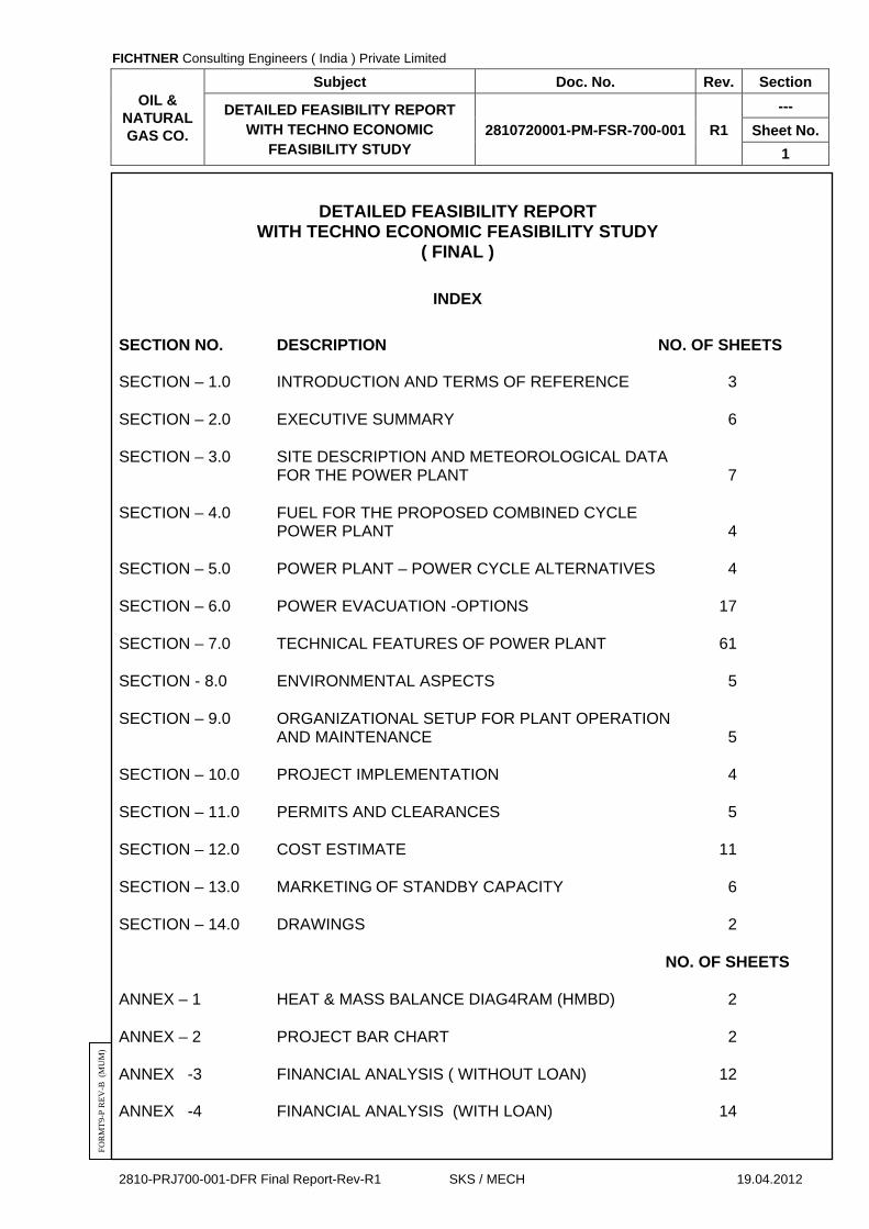
INDEX
SECTION NO. DESCRIPTION NO. OF SHEETS
SECTION – 1.0 INTRODUCTION AND TERMS OF REFERENCE 3
SECTION – 2.0 EXECUTIVE SUMMARY 6
SECTION – 3.0 SITE DESCRIPTION AND METEOROLOGICAL DATA FOR THE POWER PLANT 7
SECTION – 4.0 FUEL FOR THE PROPOSED COMBINED CYCLE POWER PLANT 4
SECTION – 5.0 POWER PLANT – POWER CYCLE ALTERNATIVES 4
SECTION – 6.0 POWER EVACUATION -OPTIONS 17
SECTION – 7.0 TECHNICAL FEATURES OF POWER PLANT 61
SECTION - 8.0 ENVIRONMENTAL ASPECTS 5
SECTION – 9.0 ORGANIZATIONAL SETUP FOR PLANT OPERATION AND MAINTENANCE 5
SECTION – 10.0 PROJECT IMPLEMENTATION 4
SECTION – 11.0 PERMITS AND CLEARANCES 5
SECTION – 12.0 COST ESTIMATE 11
SECTION – 13.0 MARKETING OF STANDBY CAPACITY 6
SECTION – 14.0 DRAWINGS 2
NO. OF SHEETS
ANNEX – 1 HEAT & MASS BALANCE DIAG4RAM (HMBD) 2
ANNEX – 2 PROJECT BAR CHART 2
ANNEX -3 FINANCIAL ANALYSIS ( WITHOUT LOAN) 12 ANNEX -4 FINANCIAL ANALYSIS (WITH LOAN) 14

FICHTNER Consulting Engineers ( India ) Private Limited
OIL & NATURAL GAS CO.
Subject Doc. No. Rev. Section
DETAILED FEASIBILITY REPORT WITH TECHNO ECONOMIC
FEASIBILITY STUDY 2810720001-PM-FSR-700-001 R1
1.0
Sheet No.
1
2810-PRJ700-001-DFR Final Report-Rev-R1 SKS / MECH 19.04.2012
FO
RM
T9-
P R
EV
-B (
MU
M)
SECTION – 1.0
INTRODUCTION AND TERMS OF REFERENCE
FICHTNER Consulting Engineers ( India ) Private Limited
OIL & NATURAL GAS CO.
Subject Doc. No. Rev. Section
DETAILED FEASIBILITY REPORT WITH TECHNO ECONOMIC
FEASIBILITY STUDY 2810720001-PM-FSR-700-001 R1
1.0
Sheet No.
2
2810-PRJ700-001-DFR Final Report-Rev-R1 SKS / MECH 19.04.2012
FO
RM
T9-
P R
EV
-B (
MU
M)
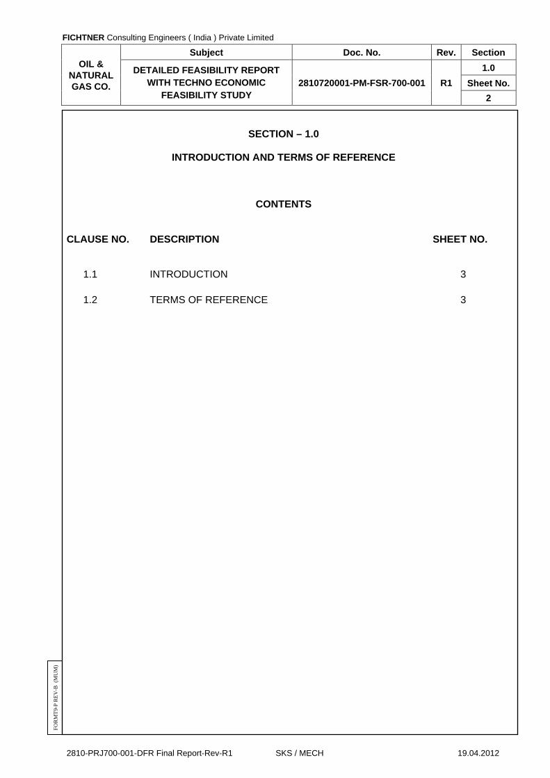
SECTION – 1.0
INTRODUCTION AND TERMS OF REFERENCE
CONTENTS
CLAUSE NO. DESCRIPTION SHEET NO.
1.1 INTRODUCTION 3
1.2 TERMS OF REFERENCE 3

FICHTNER Consulting Engineers ( India ) Private Limited
OIL & NATURAL GAS CO.
Subject Doc. No. Rev. Section
DETAILED FEASIBILITY REPORT WITH TECHNO ECONOMIC
FEASIBILITY STUDY 2810720001-PM-FSR-700-001 R1
1.0
Sheet No.
3
2810-PRJ700-001-DFR Final Report-Rev-R1 SKS / MECH 19.04.2012
FO
RM
T9-
P R
EV
-B (
MU
M)
SECTION - 10
INTRODUCTION AND TERMS OF REFERENCE
1.1 INTRODUCTION
1.1.1 Oil & Natural Gas Corporation (ONGC) has proposed to set up a stand-by power
generating unit at Hazira gas processing complex; Gujarat near the existing Cogeneration plant. The proposed CCPP unit is to be designated as a self contained unit.
1.1.2 ONGC has appointed FICHTNER Consulting Engineers (FI); Mumbai for preparing a
Detailed Feasibility Report (DFR) in Phase-I for the proposed combined cycle power project including techno economic feasibility study.
1.2 TERMS OF REFERENCE 1.2.1 The detailed feasibility study shall contain the following details.
a. Executive summary.
b. System layouts with desirable configuration & alternatives, comparative advantages and disadvantages.
c. Civil Works
d. Mechanical systems
e. Electrical systems
f. Control and Instrumentation Systems
g. Water Systems
h. Fuel Systems
i. Effluent Management Systems
j. Utilities and Infrastructure
k. Power evacuation system
l. Hookup and interconnection
m. Safety and Environmental aspects
n. Statutory Requirements and clearances
o. Marketing of standby capacity (Existing and proposed combined)
p. Cost estimate (Capex & Opex)
q. Project implementation schedule.
r. Manpower requirement
s. Adequacy checks & Bottlenecks of existing system.
1.2.3 The evaluation & study results are provided in the following sections of the report. In addition to detailing the technical aspects, this report also covers the project cost estimate in current price levels.

FICHTNER Consulting Engineers ( India ) Private Limited
OIL & NATURAL GAS CO.
Subject Doc. No. Rev. Section
DETAILED FEASIBILITY REPORT WITH TECHNO ECONOMIC
FEASIBILITY STUDY 2810720001-PM-FSR-700-001 R1
2.0
Sheet No.
1
2810-PRJ700-001-DFR Final Report-Rev-R1 SKS / MECH 19.04.2012
FO
RM
T9-
P R
EV
-B (
MU
M)
SECTION – 2.0
EXECUTIVE SUMMARY

FICHTNER Consulting Engineers ( India ) Private Limited
OIL & NATURAL GAS CO.
Subject Doc. No. Rev. Section
DETAILED FEASIBILITY REPORT WITH TECHNO ECONOMIC
FEASIBILITY STUDY 2810720001-PM-FSR-700-001 R1
2.0
Sheet No.
2
2810-PRJ700-001-DFR Final Report-Rev-R1 SKS / MECH 19.04.2012
FO
RM
T9-
P R
EV
-B (
MU
M)
SECTION – 2.0
EXECUTIVE SUMMARY
CONTENTS
CLAUSE NO. DESCRIPTION SHEET NO.
2.1 INTRODUCTION 3
2.2 NEED FOR THE PROJECT 3
2.3 FAVOURABLE FACTORS FOR THE PROJECT 3
2.4 ANALYSIS OF ALTERNATIVES 4
2.5 PLANT PARAMETERS 4
2.6 BASIC REQUIREMENTS 5
2.7 PROJECT COST AND RELATED PARAMETERS 5
2.8 PLANT OPERATION AND MARKETING OF STANDBY CAPACITY 6
2.9 CONCLUSION 6
2.10 IMPLEMENTATION SCHEDULE 6
2.11 ORGANISATION CHART FOR OPERATION AND MAINTENANCE (O & M) 6

FICHTNER Consulting Engineers ( India ) Private Limited
OIL & NATURAL GAS CO.
Subject Doc. No. Rev. Section
DETAILED FEASIBILITY REPORT WITH TECHNO ECONOMIC
FEASIBILITY STUDY 2810720001-PM-FSR-700-001 R1
2.0
Sheet No.
3
2810-PRJ700-001-DFR Final Report-Rev-R1 SKS / MECH 19.04.2012
FO
RM
T9-
P R
EV
-B (
MU
M)
SECTION – 2.0
EXECUTIVE SUMMARY
2.1 INTRODUCTION
2.1.1 Oil & Natural Gas Corporation (ONGC) has proposed to set up a stand-by power generating unit at Hazira gas processing complex; Gujarat near the existing Cogeneration plant. The proposed CCPP unit is to be designated as a self-contained unit.
2.1.2 The new combined cycle cogeneration plant is proposed within Hazira complex
adjacent to the existing cogeneration power plant and is to be designed as a self contained unit which will be a stand-by for the existing generating unit for supplying uninterrupted and reliable power and process steam at required parameters.
2.2 NEED FOR THE PROJECT
2.2.1 ONGC is having a gas turbine based captive power plant (CPP) at Hazira unit, which is presently able to meet its power and steam requirement. However during any maintenance or shutdown of these units, there is no standby facility available.
2.2.2 The present CPP cannot operate during flood which occurs during heavy monsoon.
2.2.3 Hence it is felt that a standby power generating unit installed in such a way as to operate even during flood will be of much beneficial to Hazira complex.
2.3 FAVOURABLE FACTORS FOR THE PROJECT
2.3.1 Fuel (Natural Gas) will be made available within ONGC complex through the existing distribution terminal.
2.3.2 Water for the combined cycle power plant shall be sourced from the existing facilities.
2.3.3 Adequate land for the standby power plant is available adjacent to the existing power plant.
2.3.4 The power plant will be hooked up to the GETCO substation through 66kV transmission systems. However final clearance has to be obtained from GETCO for additional power export through their transmission network. In this regard GETCO will require quantum of power to be injected to their system and the tentative time schedule of such power export for carrying out their power system studies . ONGC may accordingly approach GETCO for their clearance.
2.3.5 Surplus Power can be sold to trading companies / electricity board / any major user at reasonable profit margin.
2.3.6 Due to growing power shortage in the region, reasonably good sale tariff can be expected for the power.

FICHTNER Consulting Engineers ( India ) Private Limited
OIL & NATURAL GAS CO.
Subject Doc. No. Rev. Section
DETAILED FEASIBILITY REPORT WITH TECHNO ECONOMIC
FEASIBILITY STUDY 2810720001-PM-FSR-700-001 R1
2.0
Sheet No.
4
2810-PRJ700-001-DFR Final Report-Rev-R1 SKS / MECH 19.04.2012
FO
RM
T9-
P R
EV
-B (
MU
M)
2.4 ANALYSIS OF ALTERNATIVES
2.4.1 Following alternate configurations were considered initially and studied for feasibility and economic viability.
2.4.1.1 Alternative 1 - One no of GTG (frame 6 m/c) with One no heat recovery steam generators (HRSG) and one number of Steam Turbine Generator (STG).
2.4.1.2 Alternative 2- Two nos. of GT (frame 5 m/c) with two nos. heat recovery steam generators (HRSG) and one number of Steam Turbine Generator (STG)
2.4.1.3 It was found that for alternative 1, the initial investment is less. The plant heat rate is much lower compared to Alternative 2. Hence the Alternative 1 was selected for further detailed feasibility study.
2.4.2 The brief comparison of the two alternatives is given below.
S. No.
Description Unit Alternative-I
(1GTG, IHRSG, 1STG)
Alternative-II (1GTG,
IHRSG, 1STG)
1 Project Cost Rs. Crores 249.20 319.10
2 Debt Equity Ratio 0:100 0:100
3 Interest on Loan % p.a. 11 11
4 Landed cost of Fuel Rs/s.c.m 2.668 2.668
Gross Heat Rate Kcal/KWh 1880 2100
4 Cost of power per unit from proposed CCPP in first year
Rs./KWh 2.50 3.09
5 Net power available for sale
Lakhs kWH
2730.15 2739.49
6 Projected sale tariff Rs./KWh 3.82 3.82 7 Annual profit before
interest, depreciation and tax
Rs Crores 7989.72 7615.99
8 Straight Payback Period
Years 3.12 4.19
2.4.3 Based on the above it is apparent that Alternative-I is more attractive in terms of less
initial investment and lower payback period.
2.5 PLANT PARAMETERS
2.5.1 The combined cycle power plant (CCPP) shall consist of one (1No.) GTG, one (1 No.) HRSG and 1 (No.) STG with gross output of 51 MW. The GTG of model CC106 (frame 6 m/c) shall have site rating of 33 MW and STG with gross output of 18 MW.
2.5.2 Induced draft cooling tower with cooling tower capacity of 5,200 m3/hr.
FICHTNER Consulting Engineers ( India ) Private Limited
OIL & NATURAL GAS CO.
Subject Doc. No. Rev. Section
DETAILED FEASIBILITY REPORT WITH TECHNO ECONOMIC
FEASIBILITY STUDY 2810720001-PM-FSR-700-001 R1
2.0
Sheet No.
5
2810-PRJ700-001-DFR Final Report-Rev-R1 SKS / MECH 19.04.2012
FO
RM
T9-
P R
EV
-B (
MU
M)
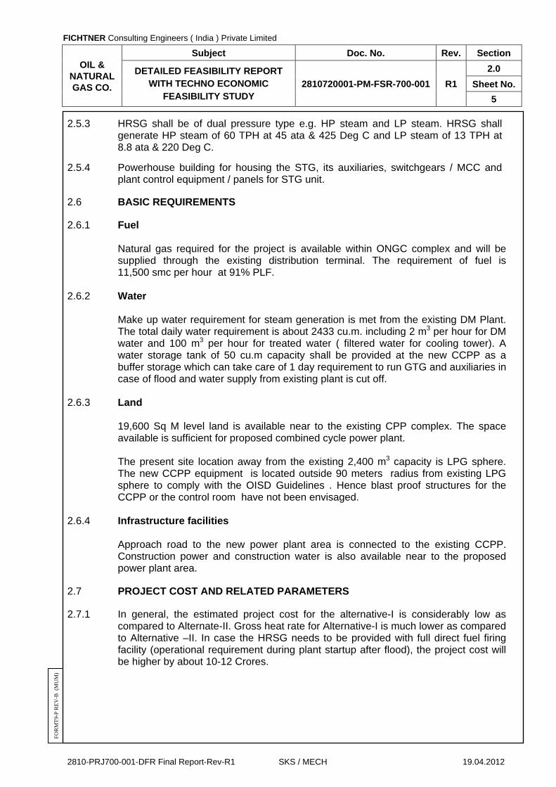
2.5.3 HRSG shall be of dual pressure type e.g. HP steam and LP steam. HRSG shall generate HP steam of 60 TPH at 45 ata & 425 Deg C and LP steam of 13 TPH at 8.8 ata & 220 Deg C.
2.5.4 Powerhouse building for housing the STG, its auxiliaries, switchgears / MCC and plant control equipment / panels for STG unit.
2.6 BASIC REQUIREMENTS
2.6.1 Fuel Natural gas required for the project is available within ONGC complex and will be
supplied through the existing distribution terminal. The requirement of fuel is 11,500 smc per hour at 91% PLF.
2.6.2 Water
Make up water requirement for steam generation is met from the existing DM Plant. The total daily water requirement is about 2433 cu.m. including 2 m3 per hour for DM water and 100 m3 per hour for treated water ( filtered water for cooling tower). A water storage tank of 50 cu.m capacity shall be provided at the new CCPP as a buffer storage which can take care of 1 day requirement to run GTG and auxiliaries in case of flood and water supply from existing plant is cut off.
2.6.3 Land
19,600 Sq M level land is available near to the existing CPP complex. The space available is sufficient for proposed combined cycle power plant.
The present site location away from the existing 2,400 m3 capacity is LPG sphere.
The new CCPP equipment is located outside 90 meters radius from existing LPG sphere to comply with the OISD Guidelines . Hence blast proof structures for the CCPP or the control room have not been envisaged.
2.6.4 Infrastructure facilities
Approach road to the new power plant area is connected to the existing CCPP. Construction power and construction water is also available near to the proposed power plant area.
2.7 PROJECT COST AND RELATED PARAMETERS
2.7.1 In general, the estimated project cost for the alternative-I is considerably low as compared to Alternate-II. Gross heat rate for Alternative-I is much lower as compared to Alternative –II. In case the HRSG needs to be provided with full direct fuel firing facility (operational requirement during plant startup after flood), the project cost will be higher by about 10-12 Crores.

FICHTNER Consulting Engineers ( India ) Private Limited
OIL & NATURAL GAS CO.
Subject Doc. No. Rev. Section
DETAILED FEASIBILITY REPORT WITH TECHNO ECONOMIC
FEASIBILITY STUDY 2810720001-PM-FSR-700-001 R1
2.0
Sheet No.
6
2810-PRJ700-001-DFR Final Report-Rev-R1 SKS / MECH 19.04.2012
FO
RM
T9-
P R
EV
-B (
MU
M)
2.8 PLANT OPERATION AND MARKETING OF STANDBY CAPACITY
Approximate projected tariff rate of Rs.3.82 /Kwh for sale of power at the point of injection at ONGC, Hazira complex is achievable considering the present power purchase tariff offered by the various power trading companies in the market as covered in the section-13.0. However in case of sale of power to electricity board a lower tariff is expected. Considering the small volume of surplus power available with ONGC, it is expected that the sale of power through power trading companies is more profitable. The existing CPP (3 units of frame 5 GE machines) generate about 60 MW of power . The present plant load of ONGC is around 31 MW. ONGC is wheeling about 15 MW of power to their sister unit in Mehsana in Gujarat. Thus the total requirement of ONGC is around 46 MW. Considering the present norms of captive power generation policy, a minimum 51% of the total power generation of 111 MW (existing 60 MW and new CCPP of 51 MW ) shall be self consumption by the plant and balance maximum of 49 % power can be exported on annualized basis. Hence considering above the new CCPP plant is recommended to run at a lower plant load factor (PLF) in order to restrict the export of power as per captive power generation norms. As per the present load of ONGC the new CCPP is expected to operate at a PLF of around 63% . The cost of generation and financial analysis of the new CCPP is based on the 63% PLF .This PLF can be improved in future if ONGC Hazira plant requires additional power for future expansion in Hazira plant or wheeling to other ONGC units elsewhere.
2.9 CONCLUSION
2.9.1 Considering the two alternatives discussed in section 5.0 the alternative I (one GTG, one HRSG & one STG ) has been recommended for the proposed combined cycle power plant based on following considerations :
Higher PLF for compliance with captive power generation norms Better plant heat rate Lower project cost. Lower payback period
2.10 IMPLEMENTATION SCHEDULE
2.10.1 With the plant configuration proposed, the estimated period for the commissioning of the combined cycle power plant is 24 months from the date of placement of order. The broad activity schedule is enclosed as Annex-2 with this report.
2.11 ORGANISATION CHART FOR OPERATION AND MAINTENANCE (O & M)
2.11.1 The suggested O & M organization chart is covered in section 9 with this report.
FICHTNER Consulting Engineers ( India ) Private Limited
OIL & NATURAL GAS CO.
Subject Doc. No. Rev. Section
DETAILED FEASIBILITY REPORT WITH TECHNO ECONOMIC
FEASIBILITY STUDY 2810720001-PM-FSR-700-001 R1
3.0
Sheet No.
1
2810-PRJ700-001-DFR Final Report-Rev-R1 SKS / MECH 19.04.2012
FO
RM
T9-
P R
EV
-B (
MU
M)
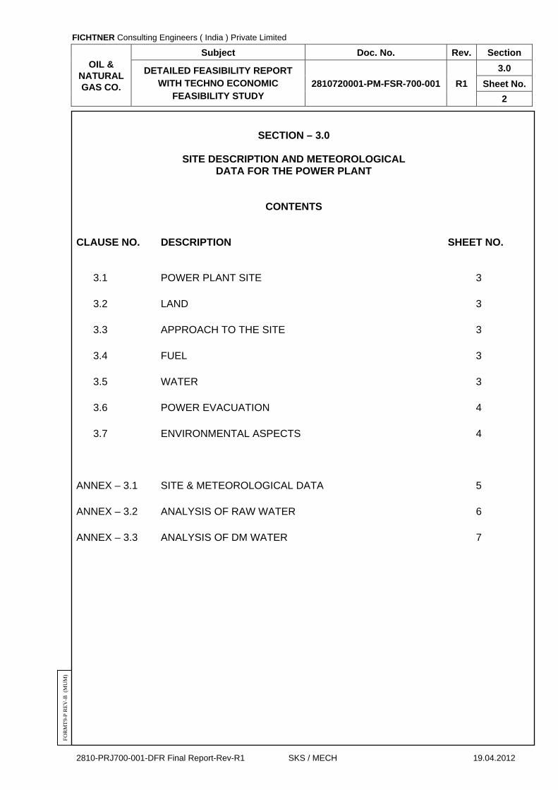
SECTION – 3.0
SITE DESCRIPTION AND METEOROLOGICAL DATA FOR THE POWER PLANT
FICHTNER Consulting Engineers ( India ) Private Limited
OIL & NATURAL GAS CO.
Subject Doc. No. Rev. Section
DETAILED FEASIBILITY REPORT WITH TECHNO ECONOMIC
FEASIBILITY STUDY 2810720001-PM-FSR-700-001 R1
3.0
Sheet No.
2
2810-PRJ700-001-DFR Final Report-Rev-R1 SKS / MECH 19.04.2012
FO
RM
T9-
P R
EV
-B (
MU
M)
SECTION – 3.0
SITE DESCRIPTION AND METEOROLOGICAL
DATA FOR THE POWER PLANT
CONTENTS
CLAUSE NO. DESCRIPTION SHEET NO.
3.1 POWER PLANT SITE 3
3.2 LAND 3
3.3 APPROACH TO THE SITE 3
3.4 FUEL 3
3.5 WATER 3
3.6 POWER EVACUATION 4
3.7 ENVIRONMENTAL ASPECTS 4
ANNEX – 3.1 SITE & METEOROLOGICAL DATA 5
ANNEX – 3.2 ANALYSIS OF RAW WATER 6
ANNEX – 3.3 ANALYSIS OF DM WATER 7

FICHTNER Consulting Engineers ( India ) Private Limited
OIL & NATURAL GAS CO.
Subject Doc. No. Rev. Section
DETAILED FEASIBILITY REPORT WITH TECHNO ECONOMIC
FEASIBILITY STUDY 2810720001-PM-FSR-700-001 R1
3.0
Sheet No.
3
2810-PRJ700-001-DFR Final Report-Rev-R1 SKS / MECH 19.04.2012
FO
RM
T9-
P R
EV
-B (
MU
M)
SECTION – 3.0
SITE DESCRIPTION AND METEROLOGICAL DATA FOR THE POWER PLANT
3.1 POWER PLANT SITE 3.1.1 The plant would be located at ONGC gas processing plant in Hazira adjacent to the
existing captive cogeneration power plants. The following factors which influence the site selection have been considered in assessing the suitability of the site for the proposed plant.
a. Availability of required land for locating the power plant.
b. Suitability of land from topography & geological aspects.
c. Proximity to rail/road to facilitate transport of equipment / materials.
d. Availability of adequate quantity of fuel and fuel transport facility.
e. Availability of adequate quantity of water to meet cooling and DM water requirements.
f. Facility for interconnection with transmission and distribution system for evacuation of power.
3.2 LAND 3.2.1 It is estimated that an area of about 4.5 acres is available for the proposed power
plant towards east side of existing captive cogeneration power plant and the area for cooling tower has been allotted adjacent to the proposed site after 7.5 Mtr. Wide road towards west side of LPG loading gantry.
3.3 APPROACH TO THE SITE 3.3.1 The proposed site is located at about 20 Km from Surat town and the National
highway NH- 8 is about 30 Km from the site. The site is well connected by road & rail. Nearest harbour is around 10 Km away and nearest airport is located about 10 Km away from the site.
3.4 FUEL 3.4.1 The fuel for the power plant shall be Natural gas and will be supplied from the gas
processing plant through the existing distribution terminal. 3.5 WATER 3.5.1 Water is required for power cycle make-up, service, drinking, cooling of steam
condenser, STG auxiliaries, GTG auxiliaries and other auxiliaries. It is proposed to supply the above requirements from the existing water treatment plant. Fire water requirement will be met from the existing raw water storage and pumping facility.

FICHTNER Consulting Engineers ( India ) Private Limited
OIL & NATURAL GAS CO.
Subject Doc. No. Rev. Section
DETAILED FEASIBILITY REPORT WITH TECHNO ECONOMIC
FEASIBILITY STUDY 2810720001-PM-FSR-700-001 R1
3.0
Sheet No.
4
2810-PRJ700-001-DFR Final Report-Rev-R1 SKS / MECH 19.04.2012
FO
RM
T9-
P R
EV
-B (
MU
M)
3.6 POWER EVACUATION 3.6.1 The power generation in the power plant shall be at 11kV level. The11kV power
generated will be stepped up to 66kV voltage level using generator transformers and 66kV power will be evacuated to 66kV grid through transmission lines.
3.6.2 It is proposed to evacuate the power to the nearest GETCO 220/66kV Ichhapur substation which is about 5 KM from the site through 66kV transmission lines.
3.7 ENVIRONMENTAL ASPECTS 3.7.1 The proposed land is located within ONGC complex and there is no human
resettlement is involved. All necessary measures would be taken in the design of the plant to prevent any adverse impact on the ecology. The detailed environmental aspects are covered in Section – 8.0
FICHTNER Consulting Engineers ( India ) Private Limited
OIL & NATURAL GAS CO.
Subject Doc. No. Rev. Section
DETAILED FEASIBILITY REPORT WITH TECHNO ECONOMIC
FEASIBILITY STUDY 2810720001-PM-FSR-700-001 R1
3.0
Sheet No.
5
2810-PRJ700-001-DFR Final Report-Rev-R1 SKS / MECH 19.04.2012
FO
RM
T9-
P R
EV
-B (
MU
M)
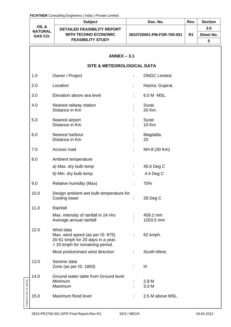
ANNEX – 3.1
SITE & METEOROLOGICAL DATA
1.0 Owner / Project : ONGC Limited. 2.0 Location : Hazira; Gujarat. 3.0 Elevation above sea level : 6.0 M MSL. 4.0 Nearest railway station : Surat. Distance in Km : 20 Km 5.0 Nearest airport : Surat Distance in Km : 10 Km 6.0 Nearest harbour : Magdalla. Distance in Km : 20 7.0 Access road : NH-8 (30 Km) 8.0 Ambient temperature
a) Max. dry bulb temp : 45.6 Deg C
b) Min. dry bulb temp : 4.4 Deg C 9.0 Relative humidity (Max) : 70% 10.0 Design ambient wet bulb temperature for Cooling tower : 28 Deg C 11.0 Rainfall
Max. intensity of rainfall in 24 Hrs : 459.2 mm Average annual rainfall : 1203.5 mm 12.0 Wind data Max. wind speed (as per IS: 875) : 62 kmph. 20-61 kmph for 20 days in a year. < 20 kmph for remaining period.
Most predominant wind direction : South-West. 13.0 Seismic data Zone (as per IS: 1893) : III 14.0 Ground water table from Ground level Minimum : 2.8 M Maximum : 3.3 M 15.0 Maximum flood level : 2.5 M above MSL.

FICHTNER Consulting Engineers ( India ) Private Limited
OIL & NATURAL GAS CO.
Subject Doc. No. Rev. Section
DETAILED FEASIBILITY REPORT WITH TECHNO ECONOMIC
FEASIBILITY STUDY 2810720001-PM-FSR-700-001 R1
3.0
Sheet No.
6
2810-PRJ700-001-DFR Final Report-Rev-R1 SKS / MECH 19.04.2012
FO
RM
T9-
P R
EV
-B (
MU
M)
ANNEX – 3.2
ANALYSIS OF RAW WATER
pH : 8.3 Turbidity NTU : < 2 Suspended solids mg/l : --- Oil / Grease mg/l : Nil Colour (Hazen units) : Nil Total hardness as CaCO3 mg/l : 115 Ca hardness as CaCO3 mg/l : 60 Mg hardness as CaCO3 mg/l : 55 M-Alkalinity as CaCO3 mg/l : 130 P-Alkalinity mg/l : Nil Copper ppm : --- Iron ppm : 0.07 Mn ppm : --- Cl ppm : 57 SO4 ppm : 12 NO3 ppm : --- Silica ppm : 23.1 Total dissolved solids ppm : 180
FICHTNER Consulting Engineers ( India ) Private Limited
OIL & NATURAL GAS CO.
Subject Doc. No. Rev. Section
DETAILED FEASIBILITY REPORT WITH TECHNO ECONOMIC
FEASIBILITY STUDY 2810720001-PM-FSR-700-001 R1
3.0
Sheet No.
7
2810-PRJ700-001-DFR Final Report-Rev-R1 SKS / MECH 19.04.2012
FO
RM
T9-
P R
EV
-B (
MU
M)
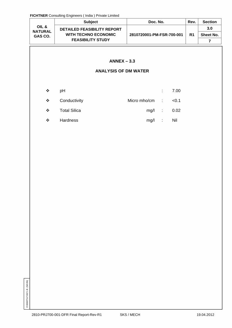
ANNEX – 3.3
ANALYSIS OF DM WATER
pH : 7.00 Conductivity Micro mho/cm : <0.1 Total Silica mg/l : 0.02 Hardness mg/l : Nil

FICHTNER Consulting Engineers ( India ) Private Limited
OIL & NATURAL GAS CO.
Subject Doc. No. Rev. Section
DETAILED FEASIBILITY REPORT WITH TECHNO ECONOMIC
FEASIBILITY STUDY 2810720001-PM-FSR-700-001 R1
4.0
Sheet No.
1
2810-PRJ700-001-DFR Final Report-Rev-R1 SKS / MECH 19.04.2012
FO
RM
T9-
P R
EV
-B (
MU
M)
SECTION – 4.0
FUEL FOR THE PROPOSED COMBINED CYCLE POWER PLANT

FICHTNER Consulting Engineers ( India ) Private Limited
OIL & NATURAL GAS CO.
Subject Doc. No. Rev. Section
DETAILED FEASIBILITY REPORT WITH TECHNO ECONOMIC
FEASIBILITY STUDY 2810720001-PM-FSR-700-001 R1
4.0
Sheet No.
2
2810-PRJ700-001-DFR Final Report-Rev-R1 SKS / MECH 19.04.2012
FO
RM
T9-
P R
EV
-B (
MU
M)
SECTION – 4.0
FUEL FOR THE PROPOSED COMBINED CYCLE
POWER PLANT
CONTENTS
CLAUSE NO. DESCRIPTION SHEET NO.
4.1 GAS TURBINE FUEL 3
4.2 FUEL FOR THE PROPOSED PLANT 3
4.3 FUEL SYSTEM 3
4.4 SELECTED FUEL AND PROCUREMENT 3
ANNEX – 4.1 FUEL ANALYSIS 4

FICHTNER Consulting Engineers ( India ) Private Limited
OIL & NATURAL GAS CO.
Subject Doc. No. Rev. Section
DETAILED FEASIBILITY REPORT WITH TECHNO ECONOMIC
FEASIBILITY STUDY 2810720001-PM-FSR-700-001 R1
4.0
Sheet No.
3
2810-PRJ700-001-DFR Final Report-Rev-R1 SKS / MECH 19.04.2012
FO
RM
T9-
P R
EV
-B (
MU
M)
SECTION – 4.0
FUEL FOR THE PROPOSED COMBINED CYCLE
POWER PLANT 4.1 GAS TURBINE FUEL Industrial gas turbines developed world over are basically designed for standard
pipeline quality natural gas, light distillate oils or both. The reason is that these fuels are clean with good combustion characteristics resulting in better machine availability. Of the above fuels, the natural gas gives a better turbine heat rate since natural gas being a clean fuel; it facilitates to go for higher firing temperature in gas turbine and is an environment friendly fuel.
4.2 FUEL FOR THE PROPOSED PLANT Natural gas has been proposed as fuel for this project. The required quantity of
Natural gas is available inside the existing ONGC complex and will be supplied through pipeline by Oil & Natural Gas Corporation (ONGC) from the existing gas distribution terminal at the plant boundary. The fuel gas pressure available is 33 to 56 kg/cm2 (g) at 35 0C.
4.3 FUEL SYSTEM 4.3.1 The fuel system consists of gas receiving and metering station, gas scrubber for
removing the moisture and filter separators for removing other impurities in the gas. Since the Natural gas is a clean fuel no further treatment is required and can be fired easily in the gas turbine without any problem. In addition the sulphur content is almost nil which eliminates cold end corrosion, lesser environment impact and low stack height when compared with light distillate fuels.
4.4 SELECTED FUEL AND PROCUREMENT On the basis of the facts discussed above, and its availability at relatively lower
basic price of Rs.3200 / 1000 sm³ (including transportation charges) natural gas has been selected as the fuel for the proposed combined cycle power plant.
Natural gas will be transported through pipe lines to the project site from the existing
gas distribution terminal within ONGC complex. The composition and characteristics of the Natural gas is given in Annex - 4.1.
FICHTNER Consulting Engineers ( India ) Private Limited
OIL & NATURAL GAS CO.
Subject Doc. No. Rev. Section
DETAILED FEASIBILITY REPORT WITH TECHNO ECONOMIC
FEASIBILITY STUDY 2810720001-PM-FSR-700-001 R1
4.0
Sheet No.
4
2810-PRJ700-001-DFR Final Report-Rev-R1 SKS / MECH 19.04.2012
FO
RM
T9-
P R
EV
-B (
MU
M)
ANNEX – 4.1
FUEL ANALYSIS Fuel Details
Fuel Natural Gas (Pipeline Quality)
Component Range
% v/v
Methane : 88.25
Ethane : 5.62
Propane : 1.4.1
Iso butane : 0.12
n-butane : 0.10
Iso pentane : ---
n-pentane : ---
Hexanes + : ---
CO2 : ---
N2 : ---
Specific Gravity (ISO 6976) : 0.64284
Net Calorific value (kCal/sm³) : 8338.12
Gross Calorific value (kCal/sm3) : 9238.49
Fuel pressure at terminal point : 37 kg/cm2 (g)
Fuel temperature at terminal point : 40 Deg C

FICHTNER Consulting Engineers ( India ) Private Limited
OIL & NATURAL GAS CO.
Subject Doc. No. Rev. Section
DETAILED FEASIBILITY REPORT WITH TECHNO ECONOMIC
FEASIBILITY STUDY 2810720001-PM-FSR-700-001 R1
5.0
Sheet No.
1
2810-PRJ700-001-DFR Final Report-Rev-R1 SKS / MECH 19.04.2012
FO
RM
T9-
P R
EV
-B (
MU
M)
SECTION – 5.0
POWER PLANT – POWER CYCLE ALTERNATIVES
FICHTNER Consulting Engineers ( India ) Private Limited
OIL & NATURAL GAS CO.
Subject Doc. No. Rev. Section
DETAILED FEASIBILITY REPORT WITH TECHNO ECONOMIC
FEASIBILITY STUDY 2810720001-PM-FSR-700-001 R1
5.0
Sheet No.
2
2810-PRJ700-001-DFR Final Report-Rev-R1 SKS / MECH 19.04.2012
FO
RM
T9-
P R
EV
-B (
MU
M)
SECTION – 5.0
POWER PLANT – POWER CYCLE ALTERNATIVES
CONTENTS
CLAUSE NO. DESCRIPTION SHEET NO.
5.1 INTRODUCTION 3
5.2 ALTERNATIVES 3
5.3 SELECTION OF CYCLE COMPONENTS 3
5.4 UNIT SIZING 4
FICHTNER Consulting Engineers ( India ) Private Limited
OIL & NATURAL GAS CO.
Subject Doc. No. Rev. Section
DETAILED FEASIBILITY REPORT WITH TECHNO ECONOMIC
FEASIBILITY STUDY 2810720001-PM-FSR-700-001 R1
5.0
Sheet No.
3
2810-PRJ700-001-DFR Final Report-Rev-R1 SKS / MECH 19.04.2012
FO
RM
T9-
P R
EV
-B (
MU
M)
SECTION – 5.0
POWER PLANT – POWER CYCLE ALTERNATIVES
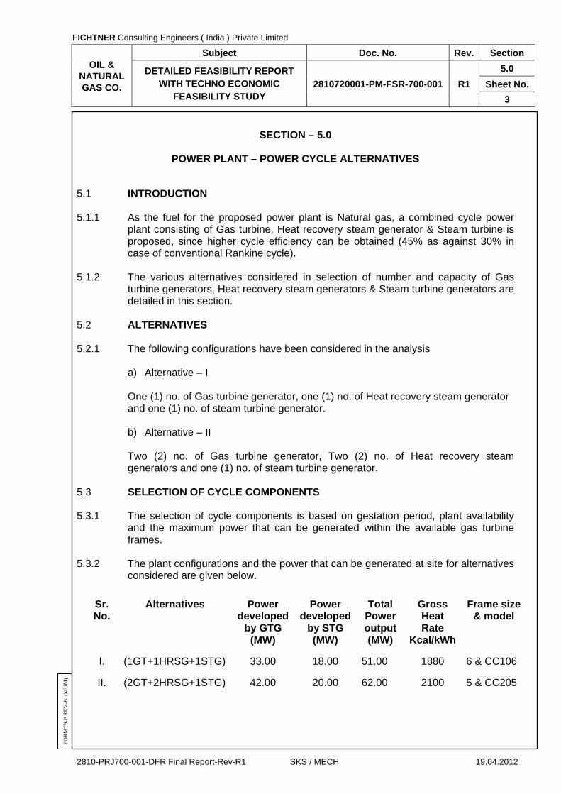
5.1 INTRODUCTION
5.1.1 As the fuel for the proposed power plant is Natural gas, a combined cycle power
plant consisting of Gas turbine, Heat recovery steam generator & Steam turbine is proposed, since higher cycle efficiency can be obtained (45% as against 30% in case of conventional Rankine cycle).
5.1.2 The various alternatives considered in selection of number and capacity of Gas
turbine generators, Heat recovery steam generators & Steam turbine generators are detailed in this section.
5.2 ALTERNATIVES 5.2.1 The following configurations have been considered in the analysis
a) Alternative – I One (1) no. of Gas turbine generator, one (1) no. of Heat recovery steam generator
and one (1) no. of steam turbine generator.
b) Alternative – II Two (2) no. of Gas turbine generator, Two (2) no. of Heat recovery steam
generators and one (1) no. of steam turbine generator. 5.3 SELECTION OF CYCLE COMPONENTS 5.3.1 The selection of cycle components is based on gestation period, plant availability
and the maximum power that can be generated within the available gas turbine frames.
5.3.2 The plant configurations and the power that can be generated at site for alternatives
considered are given below.
Sr. No.
Alternatives Power developed
by GTG (MW)
Power developed
by STG (MW)
Total Power output (MW)
Gross Heat Rate
Kcal/kWh
Frame size & model
I. (1GT+1HRSG+1STG) 33.00 18.00 51.00 1880 6 & CC106
II. (2GT+2HRSG+1STG) 42.00 20.00 62.00 2100 5 & CC205

FICHTNER Consulting Engineers ( India ) Private Limited
OIL & NATURAL GAS CO.
Subject Doc. No. Rev. Section
DETAILED FEASIBILITY REPORT WITH TECHNO ECONOMIC
FEASIBILITY STUDY 2810720001-PM-FSR-700-001 R1
5.0
Sheet No.
4
2810-PRJ700-001-DFR Final Report-Rev-R1 SKS / MECH 19.04.2012
FO
RM
T9-
P R
EV
-B (
MU
M)
5.3.3 From the above table it can be seen that single GTG plant of frame-6 m/c
configuration the gross heat rate is 1880 Kcal/ Kwh. In case of Alternative – II of frame-5 configuration, with two GTG plant the gross heat rate is 2100 Kcal/ Kwh. Also, project cost for alternative-I is lower as compared to Alternative-II. So, it is proposed to go with for Alternative-I in view of lower heat rate and lower cost.
5.4 UNIT SIZING
5.4.1 For the above considered Alternative-I, the gas turbine rating at site will be 33.00
MW. GT exhaust temperature will be of 487 Deg.C. 5.4.2 HRSG will be generating HP steam of quantity 60.00 TPH (approximately) @ 45 ata
& 425 Deg.C and LP steam of quantity 13.0 TPH @ 8.8 ata & 220 Deg.C. 5.4.3 The steam turbine output is 18.00 MW maximum continuous rating. The steam
pressure and temperature at the HP stage inlet is 45 ata and 420 Deg.C and LP stage inlet is 8.8 ata and 217 Deg.C. The heat and mass balance for Alternative-I at site conditions is shown in the Annex 1.
5.4.4 The sizing of HRSG and STG may vary slightly depending on the manufacturer’
model of the GTG as the flue gas parameters will vary based on manufacturer and model. ONGC may opt for equivalent machines also.

FICHTNER Consulting Engineers ( India ) Private Limited
OIL & NATURAL GAS CO.
Subject Doc. No. Rev. Section
DETAILED FEASIBILITY REPORT WITH TECHNO ECONOMIC
FEASIBILITY STUDY 2810720001-PM-FSR-700-001 R1
6.0
Sheet No.
1
2810-PRJ700-001-DFR Final Report-Rev-R1 SKS / MECH 19.04.2012
FO
RM
T9-
P R
EV
-B (
MU
M)
SECTION – 6.0
POWER EVACUATION -OPTIONS

FICHTNER Consulting Engineers ( India ) Private Limited
OIL & NATURAL GAS CO.
Subject Doc. No. Rev. Section
DETAILED FEASIBILITY REPORT WITH TECHNO ECONOMIC
FEASIBILITY STUDY 2810720001-PM-FSR-700-001 R1
6.0
Sheet No.
2
2810-PRJ700-001-DFR Final Report-Rev-R1 SKS / MECH 19.04.2012
FO
RM
T9-
P R
EV
-B (
MU
M)
SECTION - 6.0
POWER EVACUATION – OPTIONS
CONTENTS
CLAUSE NO. DESCRIPTION SHEET NO.
6.1 INTRODUCTION 3
6.2 INPUT DATA & ASSUMPTIONS 4
6.3 SELECTION OF POWER EVACUATION VOLTAGE 4
6.4 SELECTION OF NEW CCPP SYSTEM CONFIGURATION 10
ANNEX – 6.1 ESTIMATED FIRST ORDER COST COMPARISON 16

FICHTNER Consulting Engineers ( India ) Private Limited
OIL & NATURAL GAS CO.
Subject Doc. No. Rev. Section
DETAILED FEASIBILITY REPORT WITH TECHNO ECONOMIC
FEASIBILITY STUDY 2810720001-PM-FSR-700-001 R1
6.0
Sheet No.
3
2810-PRJ700-001-DFR Final Report-Rev-R1 SKS / MECH 19.04.2012
FO
RM
T9-
P R
EV
-B (
MU
M)
SECTION – 6.0
POWER EVACUATION -OPTIONS 6.1 INTRODUCTION
The purpose of this section of the report is to assess the alternatives for evacuation of electrical power from the proposed combined cycle power plant (CCPP) project at ONGC, Hazira, Gujrat. Power evacuation alternatives are assessed based on the maximum power evacuation option which is 2 GTGs of 21 MW each+ 20 MW STG.
ONGC intends to establish this new CCPP to serve as a standby power to the existing gas turbine based captive power plant (CPP) at the existing ONGC gas processing plant at Hazira, Surat.
In addition to grid power evacuation, the study also assesses the voltage level at
which the new CPPP generators are to be paralleled via their respective generator unit transformers
Existing CPP consists of 3 Nos. 11 kV Gas turbine generators (GT-1, 2 & 3) each of
19.2 MW connected directly to the 11kV plant generation cum distribution switchgear.
The 11 kV power generated from the proposed CCPP is connected to the grid
supply company GETCO’s 220/66 kV receiving substation at Ichhapur through a double circuit 66kV lattice steel tower overhead line established between ONGC & the GETCO substation.
The existing ONGC plant distribution and grid hook up scheme comprises:- A single bus (with two sections and 1 bus section isolator) 66 kV switchyard
with two 66/11 kV grid intake 25/31MVA transformers A 11 kV grid transformer intake and generation cum distribution switchgear
with incoming grid transformers, generators and process plant feeders. The 11kV power generated at the ONGC plant is utilized to meet the in house
process plant power requirements and excess power is evacuated to the GETCO grid at 66kV level using 66/11kV, 25/31MVA transformer.
During the meeting with ONGC on 05th Feb. 2008 and subsequent site visit,
following details were noted as input for this study.
1. ONGC intends to utilize the new 62 MW CCPP as a captive power plant.

FICHTNER Consulting Engineers ( India ) Private Limited
OIL & NATURAL GAS CO.
Subject Doc. No. Rev. Section
DETAILED FEASIBILITY REPORT WITH TECHNO ECONOMIC
FEASIBILITY STUDY 2810720001-PM-FSR-700-001 R1
6.0
Sheet No.
4
2810-PRJ700-001-DFR Final Report-Rev-R1 SKS / MECH 19.04.2012
FO
RM
T9-
P R
EV
-B (
MU
M)
2. In case the existing gas turbines are under shut down, the new CCPP shall be utilized to meet the plant load requirements.
3. The GETCO grid supply company’s intake voltage is 66 kV with the connecting double circuit 66 kV line equipped with single “DOG” ACSR (equivalent Aluminium cross section area of 100 sq. mm.) conductor per circuit.
4. GETCO approval will be required for power evacuation at a higher voltage such as 220 kV or for evacuation of power on 66 kV transmission lines that are far in excess of the currently transferred values.
5. The combination of gas and steam turbine generators (TGs) for the new CPPP is expected to be as summarized below (subject to details covered in the mechanical study) :-
2 nos. of 11 kV, 21 MW site rated gas turbine generator (GTG).
1 no. of 11 kV 20 MW steam turbine generator (STG). 6.2 INPUT DATA & ASSUMPTIONS For finalizing CCPP power evacuation scheme, based on meetings FI had with
GETCO, ONGC and site visit meetings, the following input data & assumptions were considered by FI for arriving at various options.
Existing Overall SLD of ONGC, Hazira plant – Drg No: TCE-3069-736-AU-
3001 , Rev R0.
Overall Plot Plan – Drg No: 4427-00-16-47-0001, Rev R1.
Key SLD of 220/66kV Ichhapore substation ( Day to Day energy audit report).
Point of injection of evacuated power will be GETCO Ichhapur substation where both 220 kV and 66 kV voltage levels are available for ONGC plant generation hook up from ONGC plant.
Distance of GETCO Ichhapore receiving station is approximately 5 km away from the ONGC plant at Hazira.
6.3 SELECTION OF POWER EVACUATION VOLTAGE
6.3.1 Available Generation Hook-Up Voltages The excess power available from ONGC plant based on its existing and new CCPP generation are as follows:-
Details Generation ONGC Gas Processing Plant Load
Excess Power For Export or
wheeling
Existing Generation Only
72 MVA 42 MVA
30 MVA

FICHTNER Consulting Engineers ( India ) Private Limited
OIL & NATURAL GAS CO.
Subject Doc. No. Rev. Section
DETAILED FEASIBILITY REPORT WITH TECHNO ECONOMIC
FEASIBILITY STUDY 2810720001-PM-FSR-700-001 R1
6.0
Sheet No.
5
2810-PRJ700-001-DFR Final Report-Rev-R1 SKS / MECH 19.04.2012
FO
RM
T9-
P R
EV
-B (
MU
M)
Details Generation ONGC Gas Processing Plant Load
Excess Power For Export or
wheeling
New Standby Generation Only
77.5 MVA 35.5 MVA
One Existing & All New Generation
101.25 MVA 59.5 MVA
All Existing & All New Generation
149.5 MVA 107.5 MVA
Approximately 40 MVA to a maximum of 111 MVA of excess power from the ONGC plant from new CPP will be available for wheeling to ONGC Dahej & mehsana units or export to GETCO. The nearest substation voltages available for the new CCPP power evacuation are:-
11 kV existing ONGC plant switchgear :- Existing ONGC plant generation
cum plant distribution grid intake 11 kV switchgear with fault rating of 40 kA.
66 kV existing ONGC switchyard :- Existing ONGC plant grid intake 66 kV switchyard connected to nearest GETCO Icchapore 220/66 kV substation by one double circuit lattice steel tower 66 kV overhead line
220 kV existing GETCO switchyard:- Existing GETCO 220 kV bus at the nearest GETCO Icchapore 220/33 kV substation where 220 kV hook up can be established by a new double circuit 220 kV lattice steel tower overhead line
The feasibility of evacuation of power magnitudes, over existing 66 kV lines, which are in excess of existing power transferred values will be subject to GETCO approval based on the ability of their existing Ichhapur substation to accommodate the increased power evacuation from the ONGC plant. Similarly the option of 220 kV line hook up at Ichhapur will also be subject to agreement with GETCO and subject to sorting out the new 220 kV line right of way and other environmental issues. The existing ONGC 11 kV plant generation cum distribution and grid intake switchgear has following incoming generation supply and grid intake transformer supply circuits along with outgoing process motors and plant distribution transformers:- 3 directly connected 11 kV 19.2 MW gas turbine generators.
2 incoming 25/31.5 MVA 66/11 kV grid intake transformers
outgoing motors/distribution transformer feeders as per ONGC plant SLD, TCE-3069-736-AU-3001, Rev. R0

FICHTNER Consulting Engineers ( India ) Private Limited
OIL & NATURAL GAS CO.
Subject Doc. No. Rev. Section
DETAILED FEASIBILITY REPORT WITH TECHNO ECONOMIC
FEASIBILITY STUDY 2810720001-PM-FSR-700-001 R1
6.0
Sheet No.
6
2810-PRJ700-001-DFR Final Report-Rev-R1 SKS / MECH 19.04.2012
FO
RM
T9-
P R
EV
-B (
MU
M)
The existing plant 11kV switchgear is equipped with a series fault current limiting reactor connected across its two bus sections. Assessment of fault levels on the existing system revealed that the existing system is operating with excessively high peak fault current level when all three generators are operated in parallel with the grid. Hook up of new CPP generators directly to ONGC gas plant 11 kV switchgear will further worsen the fault situation and hence such 11 kV hook up is therefore not possible. In fact to ensure the existing 11 kV switchgear is operated within rated short circuit current limits it is necessary to disconnect one of the existing 11 kV 19.2 MW GTG and transferred to the new CCPP With 11 kV switchgear ruled out for hook up of new CCPP generators, the remaining available voltages for new CCPP hook up are :- the existing 66 kV GETCO grid supply intake at ONGC plant utilizing the 66 kV
line circuits, provided its current carrying conductors have adequate power transfer capability
the existing 220 kV switchyard bus at the nearest GETCO Ichhapore
substation for which a new 220 kV switchyard at ONGC and a new 220 kV line will have to be established between GETCO & ONGC new CCPP
. Typical power transfer capability of 220 kV and 66 kV overhead lines based on their surge impedance loading (SIL) are as summarized below:-
kV SIL in MW
66 kV 10.89 MW
220 V 121 MW
SIL = kV2 / surge impedance (where typical OHL surge impedance is taken to be 400 Ohm)
For short lines power transfer ability can be as high as 2 to 3 times the SIL limit. Provided line lengths are small or suitable reactive compensation equipment are provided in case of long and loaded lines.
For short overhead line distances, where voltage drops are insignificant 66 kV double circuit overhead line (OHL) can transmit much higher power equal to the thermal current carrying capability of their respective conductors. The basis for comparison and selection of 220 kV or 66 kV power evacuation will be based on following considerations.
Power evacuation voltage and point of power injection will be subject to
GETCO decision based on the findings of their in-house power grid system studies.

FICHTNER Consulting Engineers ( India ) Private Limited
OIL & NATURAL GAS CO.
Subject Doc. No. Rev. Section
DETAILED FEASIBILITY REPORT WITH TECHNO ECONOMIC
FEASIBILITY STUDY 2810720001-PM-FSR-700-001 R1
6.0
Sheet No.
7
2810-PRJ700-001-DFR Final Report-Rev-R1 SKS / MECH 19.04.2012
FO
RM
T9-
P R
EV
-B (
MU
M)
Power evacuation at 220kV level will require establishment of new route which has right of way issues in which case it may be more practical to replace the existing 66kV OHL by 220kV OHL using the existing 66 kV line route
Full power evacuation at 66kV which is subject to GETCO agreeing on higher power intake at 66 kV.
This will require additional lines or if existing tower is to be utilized due to right of way and switchyard bay space considerations then there may be need for replacement of the existing 66kV conductors with higher current carrying super heat-resistant conductors suitable for evacuating more than 60 MVA of power at 66 kV
Life cycle cost comparison of options (i.e capital cost + capitalised cost of losses of 220 kV & 66 kV option) including capitalization of losses.
Availability of space at GETCO Ichhapur S/S for new bays required for 220 kV evacuation or 66 kV evacuation with additional 66 kV OHL.
Following sections compare the power evacuation options using existing 66 kV OHL or by establishment of new 220 kV OHL to Ichhapur S/S
6.3.2 Comparison of 66 kV & 220 kV Power Evacuation Options
220 kV Power evacuation
Power evacuation at 220 kV level will require establishment of a new 220 kV double circuit overhead line and a new 220kV switchyard at the ONGC plant.
220 kV option is not techno-economically very attractive due to following
considerations:-
1. Constraints in acquiring land for obtaining additional right of way for the 220kV transmission line
2. Right of way clearance could take in-definite time. This will effect the project execution and completion.
3. Space constraints for putting an additional 220kV receiving bay at GETCO Ichhapur Sub station
4. High initial capital cost
5. The initial capital cost , cost of losses over a 25 year period at 12 % interest rate is:-

FICHTNER Consulting Engineers ( India ) Private Limited
OIL & NATURAL GAS CO.
Subject Doc. No. Rev. Section
DETAILED FEASIBILITY REPORT WITH TECHNO ECONOMIC
FEASIBILITY STUDY 2810720001-PM-FSR-700-001 R1
6.0
Sheet No.
8
2810-PRJ700-001-DFR Final Report-Rev-R1 SKS / MECH 19.04.2012
FO
RM
T9-
P R
EV
-B (
MU
M)
Cost Rs in Lakh
Capital Cost of 220 kV Option 2650
Capitalized Cost of Losses Over 25 year period
1345
Total Life Cycle Cost 3995
6. GETCO approval is required for this option which will require time adding to
delays that will affect the project completion time. GETCO for 220 kV connection to their Ichhapur substation. This will also require initiation of study work by GETCO for carrying out studies and other fees.
220 kV option is therefore not very attractive and hence cannot be recommended
66kV power evacuation options
Since 220kV is ruled out as a preferred power evacuation voltage due to cost and
right of way considerations, 66kV is the next possible option for power evacuation. The following points to be addressed before evaluating the power evacuation
options.
Evaluation of existing 66 kV line conductor rating.:- As per preliminary estimate the power evacuation capability of the existing 66 kV overhead line (OHL) circuits are as below:-
o 25 MVA firm (N-1 i.e single circuit outage) power evacuation capability.
o 50 MVA total power evacuation capability with both circuits in operation
The above are based on existing DOG ACSR conductor (100 sq. mm. Aluminum) site capacity of 222 A which is calculated based on following site data:-
o Ambient temperature of 50 deg C,
o Conductor maximum temperature of 75 deg C (restricted for conductor / clamp capability and the mechanical sag considerations)
o Typical wind speed of 0.447 m/sec
o Solar intensity 1000 Watt/sq m.
o Solar absorption and emissivity for old (i.e. ONGCck) conductors.
The maximum firm power evacuation of existing 66 kV line would thus be 25 MVA with maximum power transfer possibility of 50 MVA when both circuits are in operation.

FICHTNER Consulting Engineers ( India ) Private Limited
OIL & NATURAL GAS CO.
Subject Doc. No. Rev. Section
DETAILED FEASIBILITY REPORT WITH TECHNO ECONOMIC
FEASIBILITY STUDY 2810720001-PM-FSR-700-001 R1
6.0
Sheet No.
9
2810-PRJ700-001-DFR Final Report-Rev-R1 SKS / MECH 19.04.2012
FO
RM
T9-
P R
EV
-B (
MU
M)
Feasibility of higher MVA evacuation at 66 kV:- For feasibility of hook up of
new generating system to 66 kV, the following considerations apply:-
o Need for GETCO Approval for evacuation of 95 MVA ONGC power to the existing GETCO Ichhapur 220/66kV substation.
o The feasibility of connection will depend on GETCO study of check feasibility of intake of 95 MVA power at their above 220/ 66 kV Ichhapur substation
Need for Revamp of existing 66 kV switchyard:- The existing outdoor 66
kV switchyard is a single 66 kV bus scheme with bus section isolator which is inadequate to accommodate 3 new generators in terms of following considerations:
o Shortage of Bus extension space for additional 66 kV bays for
generators at existing switchyard.
o Need for additional space for bus coupler bay that will be required once additional generators are connected. This will require major revamp of existing switchyard.
o Need for bays on either side with 66 kV line crossings required if the new generators are to be equally distributed between both sides of the 66 kV bus coupler ( Note new power plant with 3 generators will be located towards one of the 66 kV bus section side)
Need For Revamp of existing 66 kV overhead line circuits/tower
strengthening:-
To transfer 95 MVA of power based on firm line capacity the existing 66 kV lines will need retrofitting with new special super heat-resistant aluminum alloy steel reinforced conductor (supplied for example by J-Power System Corporation’s i.e. JPS high temperature low sag uprating conductor or equivalent make ) Maximum power transfer capacity by using this conductor will be double that of an equivalent size of normal ACSR conductor
If existing 66 kV line conductors are to be used then 25 to 50 MVA power can
be evacuated depending on operation of one or both conductors. All the ONGC generators cannot be operated with existing 66 kV lines, unless additional double circuit 66 kV line to GETCO is established.
Based on the above discussion and subject to GETCO approval for power evacuation at 66 kV, ONGC can consider:- the use of existing 66 kV line conductor for 30 MVA power transfer or
using an upgraded super thermal resistant conductor replacing existing conductor if higher power transfer over 30 MVA is decided by ONGC

FICHTNER Consulting Engineers ( India ) Private Limited
OIL & NATURAL GAS CO.
Subject Doc. No. Rev. Section
DETAILED FEASIBILITY REPORT WITH TECHNO ECONOMIC
FEASIBILITY STUDY 2810720001-PM-FSR-700-001 R1
6.0
Sheet No.
10
2810-PRJ700-001-DFR Final Report-Rev-R1 SKS / MECH 19.04.2012
FO
RM
T9-
P R
EV
-B (
MU
M)
Power evacuation at 66 kV level will require establishment of a new 66 kV switching substation at the ONGC gas processing plant since hooking up to existing 66 kV switchyard is not possible due to its limitations that will require major and complicated re-vamp. The 66 kV options considered are:-
Option-1 New 66 kV outdoor switchyard using existing 66 kV lines
Providing new double bus 66kV outdoor switchyard below the existing transmission line adjacent to existing 66kVplant switchyard.
This option will be the most expensive around Rs. 222 million.
Life cycle cost including capitalization of losses is around 804 million.
In this Option a new double bus 66kV outdoor switchyard below the existing OHL and adjacent to the existing 66kV switchyard will be installed. Existing GETCO 66kV incoming OHL lines will be split for entry to new 66kV switchyard & exit into the existing 66kV switchyard. Also 2 Nos. 66kV feeders will be connected to the HV side of proposed 66/33kV transformers in the new CCPP using 66kV cables. Please refer Single line Diagram-SLD.
In this option the existing switchyard is untouched
Option-2 New 66 kV GIS switchgear substation for limiting space using
existing 66 kV lines
Providing a new double bus indoor 66kV gas insulated switchgear (GIS)
This option will cost around Rs. 187 million
Life cycle cost including capitalization of losses is around 769 million
This Option will be similar to Option-1. If due to any safety or environmental constraints for accommodating 66kV outdoor switchyard in the proposed location, then 66kV Gas insulated switchgear (GIS) can be provided instead of 66kV switchyard.
6.4 SELECTION OF NEW CCPP SYSTEM CONFIGURATION
As far as possible the scheme should allow parallel operation of all the existing & new generators for eventual operation with the selected 66 kV GETCO grid supply to achieve maximum benefits in terms of proportionate load sharing between the generators The power supply configuration proposed should therefore be able to distribute the new CCPP, the existing CPP and the selected 66 kV grid power supply to each of existing plant area 11 kV load center bus sections without imposing fault and normal load flow demands that exceeds the corresponding equipment rating.

FICHTNER Consulting Engineers ( India ) Private Limited
OIL & NATURAL GAS CO.
Subject Doc. No. Rev. Section
DETAILED FEASIBILITY REPORT WITH TECHNO ECONOMIC
FEASIBILITY STUDY 2810720001-PM-FSR-700-001 R1
6.0
Sheet No.
11
2810-PRJ700-001-DFR Final Report-Rev-R1 SKS / MECH 19.04.2012
FO
RM
T9-
P R
EV
-B (
MU
M)
For such pooling it is recommended that the paralleling voltage switchgear is equipped with double bar with bus selection switches to achieving maximum flexibility in operating the grid supply, the new CCPP generation and the existing CPP generation. . In this respect the CCPP power evacuation voltage selection for parallel operation with the grid shall be dictated by the following criteria. The calculated fault currents, due to power hook up with the grid intake and existing CPP, at various voltage levels shall not exceed the existing plant switchgear as listed below
Voltage level Existing circuit breaker rating 66kV 21kA short circuit , 800A continuous 11kV existing 40kA short circuit, 3000 A continuous The calculated fault currents at various voltage levels shall not exceed the circuit breaker equipment short circuit current ratings widely available in India as mentioned below for all future switchgear. Voltage level Available circuit breaker rating For New Equipment 220kV/66kV 40kA short circuit, 3150 A continuous 33kV GIS All vendors 31.5 kA short circuit, 2500 A continuous 11kV From India:-11kV New 40 kA short circuit , 3150A
continuous (i.e 750 MVA at 11 kV) Imported :- New 50 kA short circuit , 3150A continuous at
11 kV Options for new CCPP generation paralleling
The voltages that can be utilized for paralleling of the new CCPP generators are:- 11 kV paralleling with 66 kV grid evacuation
Intermediate 33 kV paralleling with 66 kV grid evacuation
66 kV paralleling with 66 kV grid evacuation
A new double bus outdoor 66 kV switchyard or indoor 66 kV GIS switchgear is proposed for GETCO grid interconnection. The new 66 kV substation can be installed in the available space next to the existing 66 kV switchyard as proposed in the previous report section. The recommendation leaves the existing 66 kV switchyard untouched where otherwise complicated revamp activities would be required if it were to be used for hook of new CCPP generators.

FICHTNER Consulting Engineers ( India ) Private Limited
OIL & NATURAL GAS CO.
Subject Doc. No. Rev. Section
DETAILED FEASIBILITY REPORT WITH TECHNO ECONOMIC
FEASIBILITY STUDY 2810720001-PM-FSR-700-001 R1
6.0
Sheet No.
12
2810-PRJ700-001-DFR Final Report-Rev-R1 SKS / MECH 19.04.2012
FO
RM
T9-
P R
EV
-B (
MU
M)
The discussion of each of these voltage levels for generation paralleling are covered below:-
11 kV paralleling with 66 kV grid evacuation
It is apparent that adoption of 11 kV as the CCPP generation paralleling voltage is technically not feasible and was ruled out in the previous section as evacuation voltage because of fault level constraints.
In fact since existing 11 kV switchgear fault level is excessive, it is recommended that one of the three 19.2 MW gas turbine is disconnected from existing 11 kV switchgear and transferred to the new CPPP power plant scheme.
With ruling out of 11 kV as generator paralleling voltage, the next voltage level to be considered are 66 kV & 11 kV details of which are covered in the subsequent clauses.
Intermediate 33 kV paralleling with 66 kV grid evacuation
This option will involve:-
o Provision of 11 bay 33 kV double bus switchgear for paralleling the new CCPP generators vis their respective generator unit step up transformers (GSUT)
For double bus arrangement 33 V GIS will be more appropriate as
compared to selection of conventional switchgear in terms of cost, space and flexibility of operation.
Following circuits will be required at 33 kV;-
3 Nos. of generator unit circuits via their unit 11/33 kV Generator
transformer (2 for new and 1 existing GTG transferred from existing ONGC plant 11 kV switchgear to relieve fault level constraints at the existing plant)
2 Nos. of 66 / 33 kV grid connection transformer.
2 Nos. of 33 /11 kV power plant station service cum ONGC plant distribution transformer
1 No. 33 kV bus coupler
2 Nos. 33 kV VTs, one on each bus
o Provision of 2 x 100 % rated (100 MVA) outdoor oil filled 66/33 kV grid intake/evacuation transformer to interconnect the new CCPP 33 kV switchgear with the 66 kV switchyard.
o Provision of double bus 9 bay 66 kV outdoor or indoor GIS switchgear
with following bays

FICHTNER Consulting Engineers ( India ) Private Limited
OIL & NATURAL GAS CO.
Subject Doc. No. Rev. Section
DETAILED FEASIBILITY REPORT WITH TECHNO ECONOMIC
FEASIBILITY STUDY 2810720001-PM-FSR-700-001 R1
6.0
Sheet No.
13
2810-PRJ700-001-DFR Final Report-Rev-R1 SKS / MECH 19.04.2012
FO
RM
T9-
P R
EV
-B (
MU
M)
4 Nos. of 66 kV overhead line bays to break and tie in the 2 OHL circuits in and out of the new 66 kV switchyard/GIS switchgear.
2 Nos. of 66/33 kV grid connection transformer.
1 No. 66 kV bus coupler
2 Nos. 66 kV VTs, one on each bus
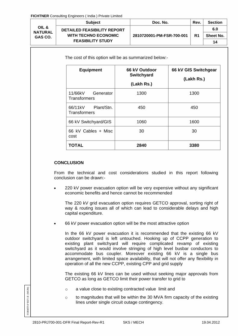
The cost of this option will be as summarized below:-
Equipment 33 kV GIS, 66 kV Outdoor Switchyard
(Lakh Rs.)
33 kV GIS, 66 kV GIS Switchgear
(Lakh Rs.)
33 kV GIS 310 310
33 kV Cables 15 15
33/11kV Gen. Transformers 950 950
33/11kVPlant/Stn. Transformers
400 400
33/66kVGrid Interconnecting Trafos.
950 950
66 kV Switchyard / GIS (9 bays)
800 1200
66 kV Cables + Misc Cost 20 20
TOTAL 3445 3845
66 kV paralleling with 66 kV grid evacuation
This option will involve:-
o Provision of double bus 12 bay 66 kV outdoor or indoor GIS switchgear with following bays
4 Nos. of 66 kV overhead line bays to break and tie in the 2 OHL
circuits in and out of the new 66 kV switchyard/GIS switchgear.
3 Nos. of generator unit circuits via their unit 11/66 kV GSUT (2 for new and 1 existing GTG transferred from existing ONGC plant 11 kV switchgear to relieve fault level constraints at the existing plant.
2 Nos. of 66/11 kV CCPP station auxiliary and ONGC plant distribution transformer.
1 No. 66 kV bus coupler
2 Nos. 66 kV VTs, one on each bus
FICHTNER Consulting Engineers ( India ) Private Limited
OIL & NATURAL GAS CO.
Subject Doc. No. Rev. Section
DETAILED FEASIBILITY REPORT WITH TECHNO ECONOMIC
FEASIBILITY STUDY 2810720001-PM-FSR-700-001 R1
6.0
Sheet No.
14
2810-PRJ700-001-DFR Final Report-Rev-R1 SKS / MECH 19.04.2012
FO
RM
T9-
P R
EV
-B (
MU
M)
The cost of this option will be as summarized below:-
Equipment 66 kV Outdoor Switchyard
(Lakh Rs.)
66 kV GIS Switchgear
(Lakh Rs.)
11/66kV Generator Transformers
1300 1300
66/11kV Plant/Stn. Transformers
450 450
66 kV Switchyard/GIS 1060 1600
66 kV Cables + Misc cost
30 30
TOTAL 2840 3380
CONCLUSION From the technical and cost considerations studied in this report following conclusion can be drawn:-
220 kV power evacuation option will be very expensive without any significant
economic benefits and hence cannot be recommended The 220 kV grid evacuation option requires GETCO approval, sorting right of
way & routing issues all of which can lead to considerable delays and high capital expenditure.
66 kV power evacuation option will be the most attractive option In the 66 kV power evacuation it is recommended that the existing 66 kV
outdoor switchyard is left untouched. Hooking up of CCPP generation to existing plant switchyard will require complicated revamp of existing switchyard as it would involve stringing of high level busbar conductors to accommodate bus coupler. Moreover existing 66 kV is a single bus arrangement, with limited space availability, that will not offer any flexibility in operation of all the new CCPP, existing CPP and grid supply
The existing 66 kV lines can be used without seeking major approvals from GETCO as long as GETCO limit their power transfer to grid to o a value close to existing contracted value limit and
o to magnitudes that will be within the 30 MVA firm capacity of the existing lines under single circuit outage contingency.

FICHTNER Consulting Engineers ( India ) Private Limited
OIL & NATURAL GAS CO.
Subject Doc. No. Rev. Section
DETAILED FEASIBILITY REPORT WITH TECHNO ECONOMIC
FEASIBILITY STUDY 2810720001-PM-FSR-700-001 R1
6.0
Sheet No.
15
2810-PRJ700-001-DFR Final Report-Rev-R1 SKS / MECH 19.04.2012
FO
RM
T9-
P R
EV
-B (
MU
M)
If power transfer in excess of existing magnitude is required from new and existing generation then ONGC will require
o GETCO approval on contract limit at 66 kV.
o Retrofitting of the existing 66 kV line conductors with low sag higher temperature/rated super thermal resistant conductors from suppliers specialized in these conductors such as JPS Japan or equivalent.
As far as generator paralleling is concerned, the 66 kV voltage is seen to be
optimum. From space & cost point of view a 66 kV GIS switchgear option is seen to be most appropriate.
This will require all new CCPP generators to be stepped up directly to 66 kV instead of adopting an intermediate voltage such as 33 kV. The recommended scheme which incorporates both generation paralleling and grid power evacuation including tie-up to existing 66 kV system is as attached in the Key SLDs.

FICHTNER Consulting Engineers ( India ) Private Limited
OIL & NATURAL GAS CO.
Subject Doc. No. Rev. Section
DETAILED FEASIBILITY REPORT WITH TECHNO ECONOMIC
FEASIBILITY STUDY 2810720001-PM-FSR-700-001 R1
6.0
Sheet No.
16
2810-PRJ700-001-DFR Final Report-Rev-R1 SKS / MECH 19.04.2012
FO
RM
T9-
P R
EV
-B (
MU
M)
ANNEX – 6.1
ESTIMATED FIRST ORDER COST COMPARISON
Estimated first order cost comparison between Power Evacuation at 220 kV level & Power evacuation at 66kV level
Sr. No. Description Estimated Cost (Rs. In lakhs)
A Power Evacuation at 220kV level using 220kV OHL
1 Double circuit 220 kV transmission Tower + conductor cost (approx. 5 kms.)
350
2 34.5 / 220 kV transformer 100 MVA , (2nos) 1000
3 220 kV outdoor switchyard Bay ( with civil work)-3 nos ( two at CCPP side & Other at GETCO side)
450
4 33kV GIS ( 11 bays + 2 CVTs) 450
5 34.5/11kV transformers 35 MVA ( 2 Nos) 400
TOTAL 2650
B Power Evacuation at 66kV level using 66kV OHL
OPTION-1
Providing new double bus 66kV outdoor switchyard below the existing transmission line
1 Double bus 66kV outdoor switchyard along with civil works ( 7 Bays + 2 Bus CVT )
800
2 34.5/66kV transformer , 100MVA, ( 2Nos) 950
3
66kV transmission line conductor replacement using super heat resistant conductors ( 2 circuits around 5Kms route length) @ 8000USD/kM for super thermal up rating conductor
120
4 33kV GIS ( 9 bays + 2 CVTs) 350
TOTAL 2220

FICHTNER Consulting Engineers ( India ) Private Limited
OIL & NATURAL GAS CO.
Subject Doc. No. Rev. Section
DETAILED FEASIBILITY REPORT WITH TECHNO ECONOMIC
FEASIBILITY STUDY 2810720001-PM-FSR-700-001 R1
6.0
Sheet No.
17
2810-PRJ700-001-DFR Final Report-Rev-R1 SKS / MECH 19.04.2012
FO
RM
T9-
P R
EV
-B (
MU
M)
Sr. No. Description Estimated Cost (Rs. In lakhs)
OPTION-2
Providing new double bus 66kV GIS
Double bus 66kV GIS ( 11 Bays + 2 Bus CVT ) 1750
66kV transmission line conductor replacement using super conductors ( 2 circuits around 5Kms route length) @ 8000USD/kM for super thermal up rating conductor
120
TOTAL 1870
Note :
1.The above costs are estimated costs and exclusive of all taxes and duties
2. Tower strengthening costs if required in 66kV option is not considered.
3. 220kV Option may not be feasible due to constraints of obtaining right of ways for 220kV OHL and non availability of space for new 220kV bay at GETCO Ichhapur sub station.
LIFE CYCLE COST ANALYSIS OF 220 kV & 66 kV POWER EVACUATION HOOK UP OPTIONS
Options Capital Cost. Lakh
Rs. Capitalisation Of
Losses (Lakh Rs.) = Cost Of Loss x
CF
Life Cycle Cost Lakh Rs.
220 kV AIS Option 2650 1344.231 3994.231 66 kV AIS Option 2220 5816.985 8036.985
66 kV GIS Option 1870 5816.985 7686.985
Losses on 95 MVA evacuation
220 kV Losses 559 kW
As Per Load Flow (Considering Zebra conductor for 220kV Option and super thermal conductor ZTACIR/AS 108/13 sq.mm for 66kV option).Double circuit OHL for 5Km route length is considered in both cases 66 kV Losses 2419 kW
CF=Capitalisation
Factor energy tariff rate 3.5 Rs/kWh rate of interest 12 % study period 25 years
CF 7.843 Factor
FICHTNER Consulting Engineers ( India ) Private Limited
OIL & NATURAL GAS CO.
Subject Doc. No. Rev. Section
DETAILED FEASIBILITY REPORT WITH TECHNO ECONOMIC
FEASIBILITY STUDY 2810720001-PM-FSR-700-001 R1
7.0
Sheet No.
1
2810-PRJ700-001-DFR Final Report-Rev-R1 SKS / MECH 19.04.2012
FO
RM
T9-
P R
EV
-B (
MU
M)
SECTION – 7.0
TECHNICAL FEATURES OF POWER PLANT

FICHTNER Consulting Engineers ( India ) Private Limited
OIL & NATURAL GAS CO.
Subject Doc. No. Rev. Section
DETAILED FEASIBILITY REPORT WITH TECHNO ECONOMIC
FEASIBILITY STUDY 2810720001-PM-FSR-700-001 R1
7.0
Sheet No.
2
2810-PRJ700-001-DFR Final Report-Rev-R1 SKS / MECH 19.04.2012
FO
RM
T9-
P R
EV
-B (
MU
M)
SECTION – 7.0
TECHNICAL FEATURES OF POWER PLANT
CONTENTS
CLAUSE NO. DESCRIPTION SHEET NO.
7.1 GENERAL 3
7.2 PLANT LAYOUT 3
7.3 CIVIL, STRUCTURAL & ARCHITECTURAL WORKS 5
7.4 MECHANICAL EQUIPMENT AND SYSTEMS 8
7.5 ELECTRICAL SYSTEM AND EQUIPMENT 27
7.6 CONTROL & INSTRUMENTATION 53
FICHTNER Consulting Engineers ( India ) Private Limited
OIL & NATURAL GAS CO.
Subject Doc. No. Rev. Section
DETAILED FEASIBILITY REPORT WITH TECHNO ECONOMIC
FEASIBILITY STUDY 2810720001-PM-FSR-700-001 R1
7.0
Sheet No.
3
2810-PRJ700-001-DFR Final Report-Rev-R1 SKS / MECH 19.04.2012
FO
RM
T9-
P R
EV
-B (
MU
M)
SECTION - 7.0
TECHNICAL FEATURES OF POWER PLANT
7.1 GENERAL 7.1.1 In this section, the details of plant layout, Mechanical Equipment & Systems,
Electrical Equipment & Systems, Control & Instrumentation and Civil Works are discussed.
7.1.2 The CCPP comprises of one (1) no. gas turbines with a power output of around
33.00 MW at site condition with one (1) no. dedicated duct fired heat recovery steam generator, one (1) no. of steam turbine of 18.00 MW gross output complete with all mechanical, electrical and control & instrumentation and auxiliaries.
7.1.3 Power generated from the CCPP will be stepped up to 66 kV and connected to
State grid for supplying power. 7.1.4 CCPP comprises of auxiliary systems like gas conditioning system, condensate
system, cooling water system, DM water, Filter water, Potable water system from existing plant, IA / SA system, Nitrogen gas purging system, fire detection & protection system, air conditioning / ventilation system, transformer yard, 66kV switchyard, 33 kV GIS, DCS, etc.
7.2 PLANT LAYOUT 7.2.1 The following factors will be considered in developing the plant layout. 1. Adequate clearances and access around each equipment for routine
inspection and maintenance. 2. Convenient power evacuation and intake connection of raw water, fuel gas
piping and road transportation. 7.2.2 The plot plan is enclosed as drawing no. 10-2810720001-G-001, Rev. A. 7.2.3 The power plant shall be classified into power block area, balance of plant area and
non-plant building area. 7.2.4 Power Block Area The following building / structures & equipment shall be located within power block
area:
Steam turbine hall HRSG and BFPs area Gas turbine area Control room & switchgear building Auxiliary transformer yard area Stacks (Bypass and main)

FICHTNER Consulting Engineers ( India ) Private Limited
OIL & NATURAL GAS CO.
Subject Doc. No. Rev. Section
DETAILED FEASIBILITY REPORT WITH TECHNO ECONOMIC
FEASIBILITY STUDY 2810720001-PM-FSR-700-001 R1
7.0
Sheet No.
4
2810-PRJ700-001-DFR Final Report-Rev-R1 SKS / MECH 19.04.2012
FO
RM
T9-
P R
EV
-B (
MU
M)
7.2.4.1 Steam turbine Hall The STG shall be accommodated in the Turbine Hall of adequate span. STG
building shall be of RCC construction. Adequate space for erection / maintenance of steam turbine/generator shall be provided in the layout.
The STG lay down area shall be provided on the generator end with necessary
generator rotor withdrawal space. The capacity and lift of crane shall be suitable for maintenance of steam turbine /
generator rotor. The operating floor for the STG shall be at +9.00 m above FFL (+2.5 M) if the steam
turbine is a radial exhaust turbine. A mezzanine floor at about 4.0 m from FFL shall also be provided for if required to
accommodate STG auxiliaries like lubricating oil system, gland sealing system, etc. The air handling room for air-conditioning system shall be located in a part of steam
turbine building. 7.2.4.2 HRSG and BFPs area The HRSG for GTG shall be located perpendicular to the GTG. The lay down area for the HRSG shall be provided on one side of the HRSG to
facilitate easy access for erection and maintenance. The boiler feed pumps shall be located adjacent to the HRSG. Deaerator shall be
integral common for HP & LP feed water circuit. 7.2.4.3 Gas Turbine Area The gas turbine shall be located inside a weather proof structure with EOT crane.
The off-base equipment of gas turbine shall be located adjacent to the main gas turbine skid. Diverter damper, bypass stack with silencer, guillotine damper, etc. shall be located between the gas turbine flue gas exhaust and the HRSG.
7.2.4.4 Control & Switchgear Building The control and switchgear building shall be located adjacent to the steam turbine
building. The control and switchgear building shall house the main control room, electrical
switchgear room, the cable spreader rooms and battery rooms. The electrical switchgears shall be located in the control building at about 4 m
above FFL (+2.5 M) with the cable spreader room beneath.

FICHTNER Consulting Engineers ( India ) Private Limited
OIL & NATURAL GAS CO.
Subject Doc. No. Rev. Section
DETAILED FEASIBILITY REPORT WITH TECHNO ECONOMIC
FEASIBILITY STUDY 2810720001-PM-FSR-700-001 R1
7.0
Sheet No.
5
2810-PRJ700-001-DFR Final Report-Rev-R1 SKS / MECH 19.04.2012
FO
RM
T9-
P R
EV
-B (
MU
M)
The main control room shall house the DCS, switchyard control / relay panels and other electrical control panels. UPS room shall be located in the main control room.
Parallel redundant HMI of the new CCPP shall also be located in the existing CPP control room.
7.2.4.5 Emergency DG room shall be adjacent to steam turbine building. 7.2.4.6 Transformers shall be located adjacent to the control and switchgear building. 7.2.5 Balance of Plant Area 7.2.5.1 The Balance of plant areas includes the following:
a) Cooling tower
b) Air compressor
c) Switch yard area.
d) Fire fighting facility extension
e) Emergency DG set.
7.2.5.2 DM water is required for boiler make-up, GT spray for NOx control will be supplied
from 1 x 50 m3 capacities storage tanks. Input for these storage tanks will be supplied from the existing DM plant. The existing DM plant at ONGC is having sufficient capacity to meet the additional requirement of around 2 m3/hr for the proposed CCPP.
7.2.5.3 Cooling water is required Condenser cooling, GT auxiliaries, STG auxiliaries and
other auxiliaries of CCPP. For this purpose a wet cooling tower of capacity 5,200 M3/Hr circulation rate is considered to cater the above. Filtered water (treated water) make-up (100 m3/hr) required to the cooling tower will be met from the existing pretreatment plant. Existing pretreatment plant is having sufficient capacity to cater the additional requirement of the above.
7.2.5.4 The air compressor shall be located adjacent to the gas turbine area. 7.2.5.5 Cooling tower shall be provided near the steam turbine building and located such
that noise level at boundary shall not exceed the limits specified by statutory authorities.
7.2.5.6 The interconnection pipe work between plant utilities and power block equipment
shall be routed through pipe racks / sleeper ways & pipe trenches. 7.3 CIVIL, STRUCTURAL & ARCHITECTURAL WORKS 7.3.1 Site Development Grade level of the site will be fixed based on the maximum flood level, topographical
survey of the plot and general layout of the surrounding area to ensure proper storm

FICHTNER Consulting Engineers ( India ) Private Limited
OIL & NATURAL GAS CO.
Subject Doc. No. Rev. Section
DETAILED FEASIBILITY REPORT WITH TECHNO ECONOMIC
FEASIBILITY STUDY 2810720001-PM-FSR-700-001 R1
7.0
Sheet No.
6
2810-PRJ700-001-DFR Final Report-Rev-R1 SKS / MECH 19.04.2012
FO
RM
T9-
P R
EV
-B (
MU
M)
water drainage of the plot. The civil and structural works for the following facilities will be undertaken as described hereunder..
7.3.2 Soil Investigation 7.3.2.1 As per the soil data available from the preliminary Soil Investigation Report which is
based on sample borehole locations. The soil layers up to a depth of 3.5m to 4.0m comprise of silty clay of high to medium plasticity. The underlying layers are cohesion less in nature comprising of sand / silty sand and clayey silt. The top silty clay layers are moderately expansive in nature. The ground water table exists at a depth of 4.0 m from the existing ground level at the time of investigation.
7.3.2.2 Proposed major Buildings / structures, pile foundations has to be given as per Soil
Investigation Report. 7.3.2.3 However, detailed geo-technical investigations for each major building / structure /
foundation will have to be carried out to assess the nature of the soil condition, based on which the type of foundations to be adopted for all the Power Plant structures will be decided.
7.3.3 Plant Roads & Drainage The plot plan drawing shows the layout of internal roads connecting individual
buildings and facilities. The roads will be of required width, having 1.5 m wide berm on either side. Storm water drainage in brick masonry will be provided as required. For process drains, catch pits will be provided at the source locations and they will be interconnected by buried RCC / MS Pipelines.
7.3.4 Gas Turbine (GT); Steam Turbine (ST) and Heat Recovery Steam Generator
(HRSG) Foundations. 7.3.4.1 GT will be of outdoor type, encased in a self-supported enclosure supported on
reinforced concrete foundation designed for the static and dynamic loads as per manufacturer’s requirements and relevant Indian Standards.
7.3.4.2 Similarly STG will be supported on reinforced concrete foundation designed for the
static and dynamic loads as per manufacturer’s requirements and relevant Indian standards. The ST/ GT foundation shall be isolated from buildings & structures. Suitable paving will be provided around the GT foundation for ease of operation & maintenance. HRSG will be supported on RCC foundations and provided with concrete paving below and around. Top level of paved areas will be maintained at minimum 200 mm above the plant grade level. HRSG area includes foundations for Main Stack & By-pass stack also.
7.3.5 Steam Turbine Generator (STG) & Control Building STG & Control building will be of RCC construction. The roof over turbine bay shall
be of pre-cast units supported on steel roof truss. Roof over control room will be of in-situ concrete supported on RCC beams. The walls of the building will be of brickwork plastered and finished as per requirements. For the air-conditioned areas in the control room bay, doors and windows of anodized aluminium will be provided;

FICHTNER Consulting Engineers ( India ) Private Limited
OIL & NATURAL GAS CO.
Subject Doc. No. Rev. Section
DETAILED FEASIBILITY REPORT WITH TECHNO ECONOMIC
FEASIBILITY STUDY 2810720001-PM-FSR-700-001 R1
7.0
Sheet No.
7
2810-PRJ700-001-DFR Final Report-Rev-R1 SKS / MECH 19.04.2012
FO
RM
T9-
P R
EV
-B (
MU
M)
and the area will be provided with false ceiling. The turbine bay will be ventilated with roof extractors. The steel structures including steel doors and windows will be painted. All fixtures and fittings in the building will be accordingly selected to withstand the climatic conditions. The flooring will be of reinforced concrete finished with floor hardener and dust preventive coating for the turbine bay and vitrified tiles for the electrical bay. Plinth protection of 1.5 m width around the building will be provided with proper drainage.
7.3.6 Works for Plant Water Systems 7.3.6.1 Civil works required for the plant water system will comprise of:
i. DM water storage tanks and auxiliaries. ii. Supports for water, gas, steam and other services pipelines etc.
7.3.6.2 Raw water is mostly required for cooling water requirements, power cycle make-up,
potable and service purpose. The water required for the above shall be supplied from the existing water treatment plant. Hence new raw water reservoir for the proposed CCPP is not required.
7.3.7 Works for Sanitary & Effluent Treatments
All buildings will be provided with toilets and water services. Effluent treatment system will be provided to conform to the environmental regulations and local norms and conditions. Effluent generated from the proposed CCPP shall be routed to the existing effluent treatment plant.
7.3.8 Works for Fuel (Natural Gas) System 7.3.8.1 The gas conditioning skid will be a semi-open steel structure with profiled metal
sheeting for roof and brick wall up to 1 m height. Open paved area will be provided around the skid.
7.3.8.2 All foundation work will be reinforced concrete construction. The pipe supports will
be structural steel work with RCC foundation. 7.3.9 Air Compressor & Nitrogen Storage Room The air compressor shed will be of provided with brick wall cladding plastered and
finished. The floor will be of RCC finished with floor hardener. Doors and windows will be of steel construction & painted.
IG requirement of new CCPP shall be met with the IG system of the existing CPP. 7.3.10 Switchyard The supporting structures for the towers and other equipment will be provided in
RCC construction. Fencing, paving with gravel filling, RCC trench, etc. will also be provided.

FICHTNER Consulting Engineers ( India ) Private Limited
OIL & NATURAL GAS CO.
Subject Doc. No. Rev. Section
DETAILED FEASIBILITY REPORT WITH TECHNO ECONOMIC
FEASIBILITY STUDY 2810720001-PM-FSR-700-001 R1
7.0
Sheet No.
8
2810-PRJ700-001-DFR Final Report-Rev-R1 SKS / MECH 19.04.2012
FO
RM
T9-
P R
EV
-B (
MU
M)
7.3.11 Water Cooled Condenser Water Cooled Condenser shall be RCC structure and provided with concrete paving
below & around. 7.3.12 Pipe & Cable Rack Pipe and cable rack will be of steel construction with rigid frames along the
transverse direction and bracing along the longitudinal direction. 7.3.13 Paving Boiler and transformer areas will be paved with P.C.C - Grade M15, 100 mm thick
over a layer of rubble soling. 7.3.14 Miscellaneous Works Other miscellaneous works for other works covering transformer yard, trenches,
culverts, compound wall, fencing, etc will be executed as per applicable Indian standards and best engineering practices as adopted for similar works.
7.3.15 Design Data The design parameters will be considered as per Annex 3.1 to Section – 3.0. 7.4 MECHANICAL EQUIPMENT AND SYSTEMS 7.4.1 Power Cycle 7.4.1.1 The combined cycle power plant shall consist of the following: 1. GTGs : One (1 No.) gas turbine with a gross power output of
around 33.00 MW at site conditions shall be provided. 2. HRSGs : Dual pressure levels Duct-fired Heat Recovery Steam
Generator with condensate pre-heater. 3. STG : One (1 no.) Multistage, single flow, condensing type steam
turbine with injection steam and with a radial exhaust with a gross output of 18.00 MW
7.4.1.2 The flue gas from the gas turbine exhaust at very high temperature shall be passed
through the dedicated HRSG for steam generation. HRSG generates steam at two pressure levels, namely HP and LP steam. The HP & LP steam from the HRSG shall be admitted into the STG. Provision for duct firing of HRSG shall be provided for process steam requirement in case of outage of GTG.
The cost of Fired HRSG is approximately 70 % more than unfired HRSG.
FICHTNER Consulting Engineers ( India ) Private Limited
OIL & NATURAL GAS CO.
Subject Doc. No. Rev. Section
DETAILED FEASIBILITY REPORT WITH TECHNO ECONOMIC
FEASIBILITY STUDY 2810720001-PM-FSR-700-001 R1
7.0
Sheet No.
9
2810-PRJ700-001-DFR Final Report-Rev-R1 SKS / MECH 19.04.2012
FO
RM
T9-
P R
EV
-B (
MU
M)
7.4.1.3 The auxiliary steam requirements for steam turbine auxiliaries such as gland sealing steam shall be catered to from main steam line through suitable pressure reducing & de-superheating stations (PRDS).
7.4.1.4 The turbine exhaust steam will be condensed in water cooled condenser.
Condensate from the condensate receiver tank will be pumped back to integral deaerator by means of condensate extraction pumps through gland steam condenser and respective condensate preheaters.
7.4.1.5 Feed water to HRSG economiser shall be fed by corresponding Boiler Feed Pumps.
The LP boiler feed pumps will take suction from the integral deaerator and will pump feed water to the common HP/LP economiser. From the common HP/LP economiser outlet, a tap off will be taken by the HP feed water pump. Balance feed water will be routed to the LP evaporator. The HP feed water pumps will supply feed water to the HP circuit. 2 x 100% LP feed water pumps and 2 x 100% HP feed water pumps will be provided for the HRSG.
7.4.1.6 Exhaust from the HRSG will be discharged to atmosphere at 35 m above local
grade level through main stack. 7.4.2 Gas Turbine Generator 7.4.2.1 One (1) No. gas turbines shall be provided. The gas turbines shall be coupled to
individual A.C. generators by means of speed reduction gear box. 7.4.2.2 The typical heat and mass balance diagram enclosed in this Detailed Project Report
is based on the following: The Gross output of GTGs for CC106 model is 33.00 MW at site ambient condition (32 Deg C).
7.4.2.3 The gas turbine shall be suitable for outdoor installation with weather proof
enclosure. 7.4.2.4 The starting device of the gas turbine shall be diesel engine starting system. 7.4.2.5 Natural gas is the fuel for the gas turbine. The gas turbine shall be designed to fire
Natural gas only. 7.4.2.6 In order to limit NOx level in the gas turbine exhaust, the GT is provided with a dry
low NOx combustor or with water injection. NOx emission level will be limited to a maximum of 50 ppmvd dry @ 15% O2.
7.4.2.7 The lube oil system of the gas turbine shall be in accordance with manufacturer’s
standard specification and design. The system shall be designed to cater to the GT requirement during normal operation/ emergency trip/shutdown and coast off as well as during start-up condition.
7.4.2.8 The GT lube oil cooler and generator air cooler shall be water cooled type. 7.4.2.9 The GT intake air system shall be provided with automatic self cleaning filters,
plenum chamber, silencer, expansion joints, ducts and supports. The pulse jet air requirement of intake air filter shall be met by GT compressor bleed air.

FICHTNER Consulting Engineers ( India ) Private Limited
OIL & NATURAL GAS CO.
Subject Doc. No. Rev. Section
DETAILED FEASIBILITY REPORT WITH TECHNO ECONOMIC
FEASIBILITY STUDY 2810720001-PM-FSR-700-001 R1
7.0
Sheet No.
10
2810-PRJ700-001-DFR Final Report-Rev-R1 SKS / MECH 19.04.2012
FO
RM
T9-
P R
EV
-B (
MU
M)
7.4.2.10 The GT exhaust shall be connected to the HRSG through suitable ducts provided
with insulation and liner plates. A diverter damper of 100% leak tight (aided by seal air fan) shall be provided between the HRSG inlet duct and the bypass stack so as to isolate the bypass stack during HRSG operation and to isolate HRSG during HRSG trip and GTG running condition. In addition to the diverter damper a 100% leak tight guillotine damper (aided by seal air system) shall be provided in HRSG side. The seal air system shall be common for both Diverter and Guillotine dampers.
7.4.2.11 Bypass stack of 30 m height shall be provided to enable simple cycle operation with
an exhaust gas silencer and the stack shall be thermally insulated from inside.
7.4.3 Steam Turbine & Auxiliaries
1 Number of turbine : One 2 Installation : Indoor 3 Application : To drive electric generator 4 Type of turbine : Multi stage, intermediate injection,
condensing, radial exhaust. 5 Normal Duty : Continuous base load and to match the
loading of gas turbine generator and HRSG. 6 Operating mode : Constant pressure/sliding pressure in
conjunction with HRSG in operation. 7. Steam Turbine rating
when GTG is operating @ 32°C
: About 18.00 MW
7.1 HP Steam inlet condition
to turbine 60.0 TPH
- Pressure at inlet : 45 bar - Temperature at inlet : 420 oC
7.2 LP Steam inlet condition
to turbine 13.0 TPH
: - Admission pressure : 8.8 bar - Admission Temperature : 217 oC 8. Permissible frequency
range : 50 Hz +/-5 %,

FICHTNER Consulting Engineers ( India ) Private Limited
OIL & NATURAL GAS CO.
Subject Doc. No. Rev. Section
DETAILED FEASIBILITY REPORT WITH TECHNO ECONOMIC
FEASIBILITY STUDY 2810720001-PM-FSR-700-001 R1
7.0
Sheet No.
11
2810-PRJ700-001-DFR Final Report-Rev-R1 SKS / MECH 19.04.2012
FO
RM
T9-
P R
EV
-B (
MU
M)
7.4.4 Heat Recovery Steam Generator
1 No. of HRSG : One (1) 2 Design code : IBR/ASME 3 Installation : Outdoor 4 Type : Unfired, Natural circulation, Two (2) pressure
stages with condensate preheater and with integral deaerator common for HP & LP feed circuit.
5 Normal Duty : Continuous base load, matching loading of
the GTGs at 32°C ambient condition and duct firing in case of outage of GTG.
6 Operating mode : Constant pressure/sliding pressure in
conjunction with steam turbine for HP pressure level. Constant pressure for LP pressure level.
7 Cycle make up water : DM Water 8 Condensate temperature
at inlet of condensate preheater
: 45.9 °C
9 Flue gas temperature at
HRSG outlet : 124°C
10 Steam purity requirement - Total dissolved solid : 1.00 ppm - Silica : 0.02 ppm - Conductivity : 0.2 micro siemens/cm at 25°C 11 HP Steam drum blow
down considered : 3% (Maximum)
12 LP steam drum blow
down considered : 3% (Maximum)
13 Main stack height : 35 m

FICHTNER Consulting Engineers ( India ) Private Limited
OIL & NATURAL GAS CO.
Subject Doc. No. Rev. Section
DETAILED FEASIBILITY REPORT WITH TECHNO ECONOMIC
FEASIBILITY STUDY 2810720001-PM-FSR-700-001 R1
7.0
Sheet No.
12
2810-PRJ700-001-DFR Final Report-Rev-R1 SKS / MECH 19.04.2012
FO
RM
T9-
P R
EV
-B (
MU
M)
7.4.5 Steam System 7.4.5.1 General The HRSGs of the combined cycle power plant generate steam at following
pressure levels, when GTGs are operating at 32°C condition for model no: CC106 i. HP Steam : 45 bar (a) and 425 0C
ii. LP Steam : 8.8 bar (a) and 217 0C The generation of steam from HRSG under base load operation of the GTG at
design ambient condition (32 oC) is as follows: i. HP Steam : 60.0 TPH
ii. LP Steam : 13.0 TPH The steam parameters at the steam turbine inlet are: i. HP Steam : 45 bar (a) and 420 0C
ii. LP Steam : 8.8 bar (a) and 213 0C A brief write up on various steam systems is as follows: 7.4.5.2 HP & LP Steam System The HP Steam system supplies high pressure superheated steam from the
superheater outlet of HRSG to the steam turbine. The LP steam system consists of superheated steam from the HRSG, which are combined together and admitted into the LP stage of steam turbine. Safety valves envisaged at the superheater outlet shall provide over-pressure protection for the HRSG and steam Piping.
The HRSG shall be provided with motorised isolating valve, non-return valve and
manual isolation valve. This shall enable isolating any HRSG from the system for maintenance / statutory inspection while other unit is in operation. A drain or vent would be provided between isolation valves of HRSG as safety consideration inline with IBR requirement (clause 350).
HP drains shall be provided with double isolation valves. These valves shall be
opened to check the leakage through isolation valve and to satisfy the safe working condition of HRSG during maintenance.
7.4.5.3 HP Steam Bypass System A bypass line shall be provided from HRSG to HP PRDS, MP PRDS and LP PRDS
for process steam requirement in case of no low load requirement or plant start-up / shutdown operation. Water for de-superheating shall be taken from the BFP/CEP discharge. Similar bypass system is provided for LP steam system also, however without de-superheating.

FICHTNER Consulting Engineers ( India ) Private Limited
OIL & NATURAL GAS CO.
Subject Doc. No. Rev. Section
DETAILED FEASIBILITY REPORT WITH TECHNO ECONOMIC
FEASIBILITY STUDY 2810720001-PM-FSR-700-001 R1
7.0
Sheet No.
13
2810-PRJ700-001-DFR Final Report-Rev-R1 SKS / MECH 19.04.2012
FO
RM
T9-
P R
EV
-B (
MU
M)
7.4.5.4 Auxiliary Steam System The auxiliary steam system is to cater to the steam requirement for turbine gland
sealing. For gland seal steam a separate pressure reducing and de-superheating station from the HP steam line shall be provided. The leak off from the gland sealing shall be taken to gland steam condenser.
7.4.5.5 Deaerator Integral deaerator shall be provided for each HRSG. Deaerators shall be of spray
type. Deaerator pressure shall be 1.433 bar (a) at full load, corresponding to a temperature of 110°C.
7.4.5.6 Feed Water System One feed water system will be provided separately for HRSG. The LP feed water
pumps (2 x100%) will draw suction from the integral deaerator and pump the feed water to the combined HP / LP economiser. From the combined HP / LP economiser outlet, the HP feed water pump will take a tap off. Remaining feed water will be routed to the LP evaporator. The HP feed water pump will supply feed water to the HP circuit. The LP feed water pumps shall be located near the deaerator, taking suction from the deaerator so as to maintain an available NPSH higher than the NPSH required by the pump. Sufficient margin on available NPSH over the required value shall be given to take care of the additional NPSH requirements during transient conditions.
Feed control station shall be provided after economisers so as to avoid steaming in
economisers. 1 x 100% Feed control station for LP circuit shall be provided. 2 x 100% Feed control stations for normal operation and 1 x 30% for start-up shall be provided for HP circuit.
Spray water for HP steam inter stage attemperators shall be taken from BFP
discharge. 7.4.6 Condensate System 7.4.6.1 Exhaust steam from the steam turbine and steam dumped from the HRSG & gland
sealing system shall be condensed in a water cooled condenser. The main parameters of water cooled condenser during site ambient conditions shall be:
Flow : 71.6 TPH
Operating pressure : 0.10 bar (a)
Cooling water inlet temperature : 33 oC
Cooling water outlet temperature : 42 oC
Terminal temperature difference between exhaust
steam and cooling water outlet : 3.8 oC

FICHTNER Consulting Engineers ( India ) Private Limited
OIL & NATURAL GAS CO.
Subject Doc. No. Rev. Section
DETAILED FEASIBILITY REPORT WITH TECHNO ECONOMIC
FEASIBILITY STUDY 2810720001-PM-FSR-700-001 R1
7.0
Sheet No.
14
2810-PRJ700-001-DFR Final Report-Rev-R1 SKS / MECH 19.04.2012
FO
RM
T9-
P R
EV
-B (
MU
M)
7.4.6.2 Non-condensable gases in the cycle water and air entering the STG and the condenser are evacuated by 2x100% vacuum pumps. During start-up, both the vacuum pumps shall be working to accelerate the generation of vacuum in condenser.
7.4.6.3 Condensate from the condensate return tank shall be pumped to the integral
deaerator of HRSG by 2 x 100% Vertical Condensate Extraction Pumps (CEP). Make up to the cycle shall be at the condensate return tank from DM plant through a control station. The control station shall be actuated by condensate return tank level controller. Cycle make-up system shall be sized to cater for initial fill up of integral deaerator and HRSG drums. Condensate excess return line shall be routed to DM water storage tanks. A gland steam condenser shall be provided upstream of Condensate Preheater (CPH). It shall condense the gland leakage steam from STG and the condensate shall be returned back to condensate return tank. The CEP minimum re-circulation line shall be taken from downstream of GSC. The recirculation control station shall be actuated by a flow element located in the CEP discharge line.
7.4.6.4 P & I diagrams for steam, feed water, condensate and gas fuel system is enclosed
as Drg. No.10-281072000-M-004, M-005, M-006 and M-007 respectively. 7.4.7 Chemical Dosing System 7.4.7.1 Chemical Feed Equipment
The cycle chemical feed system includes equipment to store and pump chemicals
for HRSGs.
General High Pressure Low Pressure
Designation Trisodium Phosphate dosing Hydrazine dosing
Service Intermittent/ Continuous (Based on blow down)
Continuous
Dosing point To HP & LP steam drums Deaerator outlet
Purpose To maintain the required pH, Phosphate Concentration
Removes traces of dissolved oxygen to relieve corrosion
Hydrazine solution shall be prepared in the solution tank. Trisodium Phosphate shall
be supplied as a powder from bags to dissolving basket in the solution tank for preparing the solution. Morpholine solution shall be prepared in the morpholine solution tank. Motorised mixer is provided in all the solution tanks. Dilution water is provided from the DM water pump discharge for all the chemical tanks.
Positive displacement metering pumps shall be installed for feeding all the chemical
solutions. The pumps shall have manual stroke length adjustment, frequency adjustment, suction strainer, and pressure relief valve etc.
FICHTNER Consulting Engineers ( India ) Private Limited
OIL & NATURAL GAS CO.
Subject Doc. No. Rev. Section
DETAILED FEASIBILITY REPORT WITH TECHNO ECONOMIC
FEASIBILITY STUDY 2810720001-PM-FSR-700-001 R1
7.0
Sheet No.
15
2810-PRJ700-001-DFR Final Report-Rev-R1 SKS / MECH 19.04.2012
FO
RM
T9-
P R
EV
-B (
MU
M)
Adjustment of dosage for hydrazine is proportional to condensate flow rate, oxygen content and specific conductivity of condensate. For Trisodium phosphate, dosage is based on periodic analysis of HRSG water drum samples for phosphate concentration and pH.
For the closed cooling water system Sodium Hydroxide (NaOH) shall be dosed
manually to increase the pH to 10.5 – 11.0. This dosage is intermittent. This chemical shall be dosed using the chemical pot provided in the circuit.
5.4.7.2 Sampling Measurement
Measurement point Type of Measurement DM water after morpholine dosing (at existing Water treatment plant end.)
pH
CEP discharge after chemical dosing Conductivity, Cation Conductivity, pH, Silica Deaerator outlet before dosing Dissolved O2 , Conductivity BFP outlet pH, Dissolved O2 Steam drum (HP & LP) Conductivity, pH, Silica Super heated Steam (LP) Cation Conductivity Super heated steam (HP) Cation conductivity, Silica
7.4.8 Piping 7.4.8.1 The piping for the power plant is grouped into power cycle piping & low pressure utility
piping. 7.4.8.2 The technical and design features of each are elaborated below: Power Cycle Piping The power cycle piping consists mainly of the following. a. Main steam (HP) piping from heat recovery steam generator is connected to a
common header which shall be routed to the steam turbine. b. LP steam piping from HRSG similar to Main steam piping. c. Steam turbine exhaust duct to water cooled condenser. d. Boiler feed water pump suction piping. e. Boiler feed water pump discharge piping.

FICHTNER Consulting Engineers ( India ) Private Limited
OIL & NATURAL GAS CO.
Subject Doc. No. Rev. Section
DETAILED FEASIBILITY REPORT WITH TECHNO ECONOMIC
FEASIBILITY STUDY 2810720001-PM-FSR-700-001 R1
7.0
Sheet No.
16
2810-PRJ700-001-DFR Final Report-Rev-R1 SKS / MECH 19.04.2012
FO
RM
T9-
P R
EV
-B (
MU
M)
f. Boiler feed water pump recirculation piping. g. Condensate extraction pumps suction piping. h. Condensate extraction pumps discharge and recirculation piping. i. Boiler blow down, steam and feed water drains and vents etc. j. Turbine by-pass lines. k. Spray water lines. Low Pressure Utility Piping The low pressure utility piping shall mainly cover the following services: a. Makeup DM water piping for closed cooling water system. b. Closed cooling water system piping c. Filtered water (potable & service) d. Instrument air e. Service air f. Nitrogen gas g. Natural gas h. Chemical dosing system. i. D.M water make-up. j. Effluent k. Vents & drains l. Fire fighting system piping. 7.4.8.3 Design Basis for Piping In the design of all pipe lines, the sizing of lines shall be based on the maximum flow
through the line and the allowable pressure drop through the lines including those of control valves, flow elements, strainers, etc., so as to maintain the required pressure at various consumption points. The thickness calculations for IBR piping shall be based on ANSI B31.1 and IBR whichever is more stringent for the design pressure and the allowable stress (as per ANSI B31.1) for the selected pipe material at the design temperature. The thickness calculation for Non IBR pipes shall be as per ANSI B31.1 for the design pressure and the allowable stress value for the selected pipe material at the design temperature. Corrosion allowance of 1.6 mm (0.75 mm for

FICHTNER Consulting Engineers ( India ) Private Limited
OIL & NATURAL GAS CO.
Subject Doc. No. Rev. Section
DETAILED FEASIBILITY REPORT WITH TECHNO ECONOMIC
FEASIBILITY STUDY 2810720001-PM-FSR-700-001 R1
7.0
Sheet No.
17
2810-PRJ700-001-DFR Final Report-Rev-R1 SKS / MECH 19.04.2012
FO
RM
T9-
P R
EV
-B (
MU
M)
HP main steam piping) shall be added in addition to tolerance on pipe thickness as required in the pipe material standard. Whenever pipe bends are used for larger wall thickness pipes, the wall thinning factor as per Power Piping design standard ANSI B31.1 shall be used and the thickness of pipe bends shall be suitably increased. The design basis and material selection for piping of different services are given below:
Steam Pipelines Generally material of construction shall be as per ANSI B31.1. Upto 427°C, pipe and
valves shall be carbon steel and for temperature more than 427°C, the material shall be alloy steel of material P22/P11.
For LP and other steam pipe lines, the material shall be carbon steel conforming to ASTM A106 Gr. B.
Boiler Feed Suction Piping The piping material shall be carbon steel conforming to ASTM A 106 Gr..B. For sizing
of the lines pump rated flow shall be considered. Boiler Feed Discharge Piping The material shall be carbon steel conforming to ASTM A 106 Gr. B. For sizing of the
lines pump rated flow shall be considered. Boiler Feed water Recirculation Piping Separate recirculation line for boiler feed pump shall be provided from the non return
cum modulating recirculation valves with necessary isolation valves and pressure break down orifices and shall be connected to the deaerator.
Boiler Blow Down, Vents, Drains, Etc. Blow down piping shall connect the drains from boiler drums, superheaters, bottom
ring headers etc., with the blow down tank. All HP & LP steam drains between HRSG isolation valve and turbine stop valve shall be connected to atmospheric flash tank. All turbine internal drains shall be connected to condenser return tank. Adequate drain lines shall be provided as per layout requirements.
Condensate Piping The piping shall be sized for the maximum flow to the condenser under various modes
of operation. The material shall be carbon steel confirming to ASTM A106 Gr. B. Filtered Water Piping The material of piping shall be carbon steel as per IS : 1239 / IS : 3589.
FICHTNER Consulting Engineers ( India ) Private Limited
OIL & NATURAL GAS CO.
Subject Doc. No. Rev. Section
DETAILED FEASIBILITY REPORT WITH TECHNO ECONOMIC
FEASIBILITY STUDY 2810720001-PM-FSR-700-001 R1
7.0
Sheet No.
18
2810-PRJ700-001-DFR Final Report-Rev-R1 SKS / MECH 19.04.2012
FO
RM
T9-
P R
EV
-B (
MU
M)
Air Pipe Line The material for air pipe line shall be galvanised carbon steel pipe (IS 1239). Tappings
shall be made from respective headers at the nearest point. Air lines shall be provided with ball valve/globe valve.
DM Water Pipe Line The DM water pipe from DM plant to the DM water storage tank and from the storage
tank to condensate return tank would be routed through suitably sized pipeline. Pipe material shall be of SS 304. The DM water line valves shall be diaphragm valves for low temperature service and gate valves of SS 304 material for high temperature service.
Natural Gas (NG) Piping for NG up to filter separator shall be of A 106 Gr. B. From filter separator to GT
the piping material shall be SS 304L/ SS 321. Nitrogen Nitrogen gas in cylinders shall be used for purging of HRSG and natural gas system.
The material of construction shall be SA 106 Gr. B. Chemical dosing System For chemical dosing system all pipelines shall be generally stainless steel. Effluent Piping for water effluent system shall be HDPE. Service and Drinking Water Pipe Line The service and drinking water pipelines shall be routed separately throughout the
power plant. The material of potable / service water piping shall be carbon steel conforming to IS 1239 GI.
Closed Cooling Water Piping The closed cooling water system shall be supplying cooling water for GTG and STG
auxiliaries and all other auxiliaries of the power plant except air compressors, vacuum pump and HVAC System. The material of piping shall be carbon steel conforming to IS:3589 for 150 NB and above. Below 150 NB the pipe shall conform to IS 1239 black.
The buried piping shall be provided with anti corrosive pipe coat tape of suitable
thickness and necessary cathodic protection shall be provided based on soil resistivity.
FICHTNER Consulting Engineers ( India ) Private Limited
OIL & NATURAL GAS CO.
Subject Doc. No. Rev. Section
DETAILED FEASIBILITY REPORT WITH TECHNO ECONOMIC
FEASIBILITY STUDY 2810720001-PM-FSR-700-001 R1
7.0
Sheet No.
19
2810-PRJ700-001-DFR Final Report-Rev-R1 SKS / MECH 19.04.2012
FO
RM
T9-
P R
EV
-B (
MU
M)
Fire Water Piping Fire water piping shall be routed from the fire water pump house of the power plant. It
shall be routed around the turbine building, GTG area, HRSG area, electrical bay, transformer yard, fuel gas area etc.
For above ground pipes of size 150 NB and above the material shall be carbon steel
as per IS : 3589 and for pipes of sizes 150 NB and below the material shall be IS : 1239 heavy (black ) grade
7.4.8.4 Valves The design, material, construction, manufacture, inspection and testing of valves &
specialties shall comply with all currently applicable standards, regulations and API/ANSI/AWWA or BS codes.
All drain & vent connections for 40kg/cm2 (a) and above rating shall be made up of two
(2) valves in series, one of the isolating type and other of the regulating type shall be provided.
All valves and specialties shall be located so that they are readily accessible for both
operation and maintenance. Wherever necessary, the valve spindles shall be extended and an approved type of pedestal hand wheel shall be provided at the next higher floor level or necessary plant form to be provided.
Valves that are to be kept locked in full 'OPEN' / 'CLOSE' position shall be provided
with a non- detachable locking arrangement comprising a chain & padlock. Motor operated valves shall be provided with hand- operated device for operating the
valves during power failure. All motor operated valves shall have open and close limit switches, torque switches integral starter with push button start / stop.
7.4.9 Insulation 7.4.9.1 All piping systems having working temperature equal to or more than 60C at all
ambient conditions as per ASTM C533 shall be normally insulated for conserving enthalpy and personnel protection.
7.4.9.2 The insulating material is selected suitably for the working temperature of the pipe. It
is essential that the material is free from shots, chlorides, oil, sulphur and other impurities and retains its density and thermal conductivity over a reasonably long period.
7.4.9.3 Insulation thickness shall be so selected that the temperature of its outside jacket
remains 60C, since it is expected that such temperature does not produce burns on human skin within a contact period of 3 seconds. The wind velocity values considered for calculating insulation thickness shall be 100 m/min for indoor installation and 300 m/min for outdoor installation at maximum ambient temperature.
FICHTNER Consulting Engineers ( India ) Private Limited
OIL & NATURAL GAS CO.
Subject Doc. No. Rev. Section
DETAILED FEASIBILITY REPORT WITH TECHNO ECONOMIC
FEASIBILITY STUDY 2810720001-PM-FSR-700-001 R1
7.0
Sheet No.
20
2810-PRJ700-001-DFR Final Report-Rev-R1 SKS / MECH 19.04.2012
FO
RM
T9-
P R
EV
-B (
MU
M)
7.4.10 Plant Water System 7.4.10.1 The plant water system comprises of the following : - Makeup water system - Potable / Service water system - Closed cooling water system 7.4.10.2 Make up Water System DM water requirement shall be met from existing 3 x 100 m3/hr capacity D.M. Plant. The quality of DM water produced shall be as follows: DM Plant outlet Total hardness ppm as CaCO3 : Nil Total Silica (Maximum) ppm as CaCO3 : <0.02 Conductivity @ 25°C micro mho/cm : <0.2 PH before morpholine dosing @25°C : 6.8-7.2 PH after morpholine dosing @ 25°C : 8.8-9.2 The Demineralised water shall be stored in a DM water storage tank of 1 x 50 m3
capacity. The tank shall be above ground, mild steel construction with rubber lining. In order to increase the pH of boiler make up water, Morpholine dosing system shall be provided. From the DM water tank, water shall be distributed using DM water distribution pumps.
Make-up water plant shall be an automatic plant with pneumatic operated valves.
Necessary instruments shall be provided for the effective monitoring of the plant. 7.4.10.3 Potable / Service Water System Potable water shall be tapped from the existing potable water network and shall be
sent to the Service / Potable water overhead tank. From the tank water shall be distributed within the power plant. “UV sterilizers” shall
be used to disinfect the potable water near the potable water outlets. Ultra violet rays shall be used to disinfect the water.
7.4.11 Auxiliary Cooling Water System 7.4.11.1 The Auxiliary cooling water system consists of the following independent system:
a) Cooling tower
b) ACW Pumps

FICHTNER Consulting Engineers ( India ) Private Limited
OIL & NATURAL GAS CO.
Subject Doc. No. Rev. Section
DETAILED FEASIBILITY REPORT WITH TECHNO ECONOMIC
FEASIBILITY STUDY 2810720001-PM-FSR-700-001 R1
7.0
Sheet No.
21
2810-PRJ700-001-DFR Final Report-Rev-R1 SKS / MECH 19.04.2012
FO
RM
T9-
P R
EV
-B (
MU
M)
7.4.11.2 Auxiliary cooling water shall be used to cool, closed circuit cooling water which
circulates through GTG lube oil coolers and generator air coolers STG lube oil cooler and STG air coolers, HRSG feed water pumps, Sampling cooler, etc.
7.4.11.3 2 x 100% pumps are provided to supply Auxiliary cooling water. 7.4.11.4 A chemical (Morpholine) addition tank shall be provided in the CCW circuit to
maintain the pH level in the system. 7.4.12 Fuel Gas System 7.4.12.1 Fuel gas for the Combined Cycle Power Plant is Natural gas. Fuel analysis is given
in Section 4.1. 7.4.12.2 Fuel gas system basically consists of receiving and metering station and gas
conditioning skid . Gas metering and receiving station shall be located near the plant boundary in GAIL area. Gas conditioning skid includes scrubber for removing the moisture and filter separator for removing other impurities in the gas. Gas condensate from the gas conditioning skid shall be collected in an under ground tank. The accumulated condensate shall be removed by tanker for final disposal.
7.4.13 Safety Aspects 7.4.13.1 Electric Motors in gas station area shall be of flame proof type. Other electrical
fittings shall be of explosion proof type. All equipment shall be earthed, while each flanged joints shall have conductors wired across the mating faces to prevent static electricity build-up. Conductor wire shall be mild steel.
7.4.13.2 Valves used for handling fuel gas shall be “Fire Safe” ball valves as per API 607. 7.4.13.3 All vents and drains provided on piping between the gas station and the GT building
shall be provided with caps to contain any inadvertent leakage in the valves. 7.4.13.4 The condensate drain tanks shall be provided with flame arrestors. 7.4.14 Cranes and Hoists
7.4.14.1 Design Criteria The criteria for selecting the crane is based on maximum load and the raising &
lowering heights of assembly/ sub assembly being lifted during maintenance work. Electric overhead travelling crane will be provided in the steam turbine building. Manual chain pulley block with Geared Trolley shall be provided for areas with
equipment/component to be lifted for erection and maintenance weighing less than 5 Tons. Electric hoist shall be provided for equipment/component weighing 5 Tons and above. The safe working loads for manual and electric hoist are based on weight of heaviest component to be lifted.

FICHTNER Consulting Engineers ( India ) Private Limited
OIL & NATURAL GAS CO.
Subject Doc. No. Rev. Section
DETAILED FEASIBILITY REPORT WITH TECHNO ECONOMIC
FEASIBILITY STUDY 2810720001-PM-FSR-700-001 R1
7.0
Sheet No.
22
2810-PRJ700-001-DFR Final Report-Rev-R1 SKS / MECH 19.04.2012
FO
RM
T9-
P R
EV
-B (
MU
M)
7.4.14.2 Cranes Electrically operated overhead traveling crane (EOT) shall be provided for the
following area: STG Hall : for maintenance of STG components EOT crane shall have all motions like hoisting, cross travel, and longitudinal travel. The gantry shall be double girder box type construction for all EOT cranes. 7.4.14.3 EOT crane for STG hall Location : Indoor
Design according to standard : IS 3177 / IS 807
Duty class : II
Capacity : 40* Tons
Heaviest part to : Generator-Rotor be lifted by the crane Speeds Fast / creep
Crane travelling speed : 15 / 1.5 m/min.
Crab traversing speed : 10 / 1 m/min.
Main hoisting speed : 1.2 / 0.12 m/min.
Auxiliary hoisting speed : 5.0 / 0.5 m/min.
Quantity : 1 No.
HOT crane of about 5T capacity will be provided for workshop. Note (*) EOT Capacity shall be based on Heaviest STG/GTG part to be lifted after
dismantling. This EOT shall not be used for STG/GTG Package erection. 7.4.14.4 Hoist The following hoists shall be provided -
Sl. No.
Description Area Qty location Duty Class
1 Chain pulley block with geared trolley
Air compressor room
1 Indoor CL- II
IS-3832
2 Chain pulley block with geared trolley
DG Room 1 Indoor CL- II
IS-3832
3. Electric hoist with electric cross travel
BFP area 1 Semi-outdoor
CL- II
IS-3928
The hoist runways (I-beams / double T beams) shall include fastenings and end
stops, etc for each hoist.

FICHTNER Consulting Engineers ( India ) Private Limited
OIL & NATURAL GAS CO.
Subject Doc. No. Rev. Section
DETAILED FEASIBILITY REPORT WITH TECHNO ECONOMIC
FEASIBILITY STUDY 2810720001-PM-FSR-700-001 R1
7.0
Sheet No.
23
2810-PRJ700-001-DFR Final Report-Rev-R1 SKS / MECH 19.04.2012
FO
RM
T9-
P R
EV
-B (
MU
M)
7.4.15 Compressed Air System 7.4.15.1 The CCPP shall require instrument air for operation of I/P converters, purge
instruments, pneumatic actuation of control valves, dampers, etc. for different systems. Service air shall be required for cleaning of filters, strainers and general purpose. Compressed air system, as detailed in this report, is envisaged to supply the air of required quality & quantity.
7.4.15.2 While estimating the instrument and service requirements a margin of 15% for spare
and leakage losses shall be considered. 7.4.15.3 Sizing The capacity and number of compressors shall be estimated based on the sum of
total Instrument air requirement plus 15% additional capacity of instrument air. ONGC has confirmed during meeting on 05.02.08 that 300 m3/hr of instrument air shall be met from the existing air system.
One (1) no. oil free, non-lubricated type screw air compressors shall be considered.
A margin of about 15% over the total compressed air requirement of the plant shall be considered while selecting the compressor capacity. Compressor shall be sized for emergency air requirement for black start of CCPP.
The individual discharges of compressors are connected to a common discharge
header which in-turn is connected to a main air receiver to dampen out pulsations. From the main air receiver one tapping is taken to air drier to obtain instrument air
quality. One tapping is taken to service air distribution system through a pressure control valve. An instrument air receiver is provided at the down stream of air drier for the storage of dry air. From the dry air receiver, distribution for instrument air is effected. The quality of instrument air at the outlet of instrument air receiver shall conform to ISA S7.3 standard.
Compressor shall be controlled by a dual control method to permit operation of the
compressor in either continuous load/unload mode or an auto start/stop mode. If the compressor selected for load/unload mode, when started, fails to start, the standby compressor shall come to operation through auto start/stop mode. In addition to the common selector switch each compressor is provided with an individual selector switch for load/unload and start/stop mode.
7.4.16 HVAC System 7.4.16.1 Design Criteria Air conditioning system is considered for the following areas:
CCR / CER / UPS / shift engineers
Instrument laboratory room.

FICHTNER Consulting Engineers ( India ) Private Limited
OIL & NATURAL GAS CO.
Subject Doc. No. Rev. Section
DETAILED FEASIBILITY REPORT WITH TECHNO ECONOMIC
FEASIBILITY STUDY 2810720001-PM-FSR-700-001 R1
7.0
Sheet No.
24
2810-PRJ700-001-DFR Final Report-Rev-R1 SKS / MECH 19.04.2012
FO
RM
T9-
P R
EV
-B (
MU
M)
For the above, the air-conditioning includes filtering, cooling and dehumidification and the supply of fresh air.
The HVAC system shall be designed conforming to following codes and standards.
IS:669 : Safety code for air conditioning
IS:660 : Safety code for mechanical refrigeration
Ventilation system shall be designed by standard Industrial practice and as per
guidelines of Association of Ventilation Engineers, India & American Council of Government Industrial Hygienic
Ventilation is considered for following areas: - All the buildings or rooms in which waste heat is generated, which has to be
removed but where temperature ranges do not necessitate air conditioning, for example switchgear room, machine hall, cable spreader room etc.
- All the building or rooms in which hazardous/toxic/acidic fumes/vapour are
present and have to be removed but where temperature ranges do not necessitate air conditioning for example Battery room.
- For all toilets For the above dry/dilution ventilation system shall be provided. 7.4.16.2 The inside conditions of the buildings will be as follows: For all air-conditioned rooms:
Temperature : 24.4 deg.C 1.1 deg.C
Relative humidity : 50% 5%
For all ventilated areas the number of air changes will be as follows:
Area Air changes per hour
STG hall 12
Switchgear room 15
Cable spreader room 15
Battery room 15
DG room 30
Toilets 15
Air compressor house 30
Stores 2

FICHTNER Consulting Engineers ( India ) Private Limited
OIL & NATURAL GAS CO.
Subject Doc. No. Rev. Section
DETAILED FEASIBILITY REPORT WITH TECHNO ECONOMIC
FEASIBILITY STUDY 2810720001-PM-FSR-700-001 R1
7.0
Sheet No.
25
2810-PRJ700-001-DFR Final Report-Rev-R1 SKS / MECH 19.04.2012
FO
RM
T9-
P R
EV
-B (
MU
M)
7.4.17 Fire Protection System 7.4.17.1 Introduction The fire protection system for the combined cycle power plant is provided for early
detection, alarm, containment and suppression of fires. An adequate fire protection system has been planned to meet the above objective and all statutory and insurance requirement of Tariff Advisory Committee (TAC) of India. A multitude of systems shall be provided to combat various types of fires in different areas of the plant and all such systems for various areas shall form a part of a centralized protection system for the entire combined cycle plant . The complete fire protection system shall comprise of the following.
i) Fire hydrant system (External and Internal)
ii) Automatic & manual fire detection & alarm system
iii) Fixed Water spray system (high velocity and medium velocity)
iv) CO2 fire suppression system for GTG (Part of GTG supply)
v) Portable fire extinguishers
The fire hydrant system requirement shall be met by existing fire water system. CCPP control room shall be provided with Automatic / manual fire detection and
alarm system using smoke and heat detectors . 7.4.17.2 Design Criteria The fire protection system shall be designed to satisfy the following:
(i) To provide facilities for fighting all types of fires that can occur in the plant.
(ii) To equip the plant for fighting atleast two simultaneous fires.
(iii) To meet the basic minimum requirements of TAC / LPA
(iv) To meet the basic requirements for approval by Chief Controller of Explosives (CCOE).
7.4.17.3 Codes & Standards The Fire Protection System shall generally be designed in conformance with Tariff
Advisory Committee (TAC). In the absence of TAC rules, for a specific aspect of design, the NFPA standards shall be adopted.
7.4.18 Effluent Collection and Disposal System The waste collection and treatment system receives, segregates, and transfers all
plant process and liquid waste streams for plant water management and ensures conformance to the statutory government guidelines prevailing in the state.
The proposed power plant effluent shall of the following kinds. They are:

FICHTNER Consulting Engineers ( India ) Private Limited
OIL & NATURAL GAS CO.
Subject Doc. No. Rev. Section
DETAILED FEASIBILITY REPORT WITH TECHNO ECONOMIC
FEASIBILITY STUDY 2810720001-PM-FSR-700-001 R1
7.0
Sheet No.
26
2810-PRJ700-001-DFR Final Report-Rev-R1 SKS / MECH 19.04.2012
FO
RM
T9-
P R
EV
-B (
MU
M)
a) Oily waste
b) Water Waste – Cooling tower blow down, boiler blow down, side stream filter backwash water.
c) Sanitary waste.
7.4.18.1 Oily Waste All the oily wastes from GTG, STG, transformer and other equipments shall be
collected individually in local pits and shall be pumped to an nearest existing PWS (Process waste system) pit.
7.4.18.2 Water Waste The plant water waste effluents are:
i. HRSG blow down.
ii. GT wash water waste
iii. Filter back wash
iv. Cooling Tower blow down
Cooling tower blow down as well as Side Stream Filter backwash water shall sent to
nearest existing OWS (Other waste system) pit. HRSG Blow down along with GT wash water shall be sent to nearest existing PWS (Process waste system) pit.
7.4.18.3 Sanitary Waste Sanitary waste from plant and canteen shall be collected in a septic tank. 7.4.18.4 Fuel Condensate The condensate from knockout drum in compressed Natural Gas System shall be
collected in underground drain tank and disposed offsite. Gas condensate detection system with addressable sensors, self-diagnostics and testing features shall be provided. The signals of detectors shall be taken to DCS for monitoring
7.4.18.5 Following is the quantity of various effluents generated from the power plant, Cooling tower blow down – 25 m3/hr i.e. 600 m3/day HRSG Blow down -- 2 m3/hr i.e. 48 m3/day Side stream filter back wash – 50 m3/day Other sources of effluent such as GT wash water, oily waste are intermittent and
quantity is also in traces.

FICHTNER Consulting Engineers ( India ) Private Limited
OIL & NATURAL GAS CO.
Subject Doc. No. Rev. Section
DETAILED FEASIBILITY REPORT WITH TECHNO ECONOMIC
FEASIBILITY STUDY 2810720001-PM-FSR-700-001 R1
7.0
Sheet No.
27
2810-PRJ700-001-DFR Final Report-Rev-R1 SKS / MECH 19.04.2012
FO
RM
T9-
P R
EV
-B (
MU
M)
7.5 ELECTRICAL SYSTEM AND EQUIPMENT 7.5.1 General Description Existing CPP consists of 3 Nos. Gas turbines (GT-1, 2 & 3) each of 19.2 MW
connected to the existing 11kV switchgear. Presently 11kV power generated is utilized to meet the in house power requirements of ONGC, Hazira complex and excess power is evacuated to the grid at 66kV level using 66/11kV, 25/31MVA transformer.
As mentioned in section-6 (Power evacuation-Options) of this document the
recommended voltage for power evacuation is 66kV.Paralleling of the generators will be done at 66kV level. The recommended scheme which incorporates both generation paralleling and grid power evacuation including tie-up to existing 66 kV system through 66kV GIS switchgear. Alternative-1 with 1 No. GTG of 33 MW + 1 No: STG of 18 MW described in section-5 of this report is considered for describing the electrical system of the new CCPP.
New CCPP (combined cycle power plant) consist of 1 No. GTG (gas turbine
generator) rated 33MW (site rated) and one STG (steam turbine generator) of 18MW with generation voltage at 11kV level. 11kV power generated from these generators are stepped up and connected to a new 66kV GIS (gas insulated switchgear) through each 11/69kVgenerator transformer. The 11kV power generated will be stepped up to 66kV and will be connected to new 66kV gas insulated switchgear. The power will be evacuated to the 66kV grid from the outgoing feeder of 66 kV GIS.
After meeting the in house (ONGC,Hazira) requirement, the excess power from the
existing as well as new CCPP will be available for power export/wheeling. This power will be exported to the nearest GETCO Ichhapur substation which is around 5 kMs away from the CCPP. Existing 66kV transmission line conductors will be replaced by higher current carrying super heat-resistant conductors suitable for evacuating upto 100 MVA power.
To handle the additional power from the new CCPP the following changes are
proposed in the existing system.
Existing GT-3 (25 MW ISO rated) presently connected to the existing 11 kV switchgear is proposed to be hooked up to the new the 66 kV CCPP GIS through 11 / 69 kV generator transformer.
Around 50% of the existing loads (approx: 45 Nos. 11 kV feeders) connected
in the 11 kV switchgear -1 to be shifted to the new 11kV switchgear at CCPP. Existing GETCO 66 kV incoming OHL lines will be split for entry to new 66 kV
GIS & exit from the new 66kV GIS to the existing 66 kV switchyard using 66kV cables.
FICHTNER Consulting Engineers ( India ) Private Limited
OIL & NATURAL GAS CO.
Subject Doc. No. Rev. Section
DETAILED FEASIBILITY REPORT WITH TECHNO ECONOMIC
FEASIBILITY STUDY 2810720001-PM-FSR-700-001 R1
7.0
Sheet No.
28
2810-PRJ700-001-DFR Final Report-Rev-R1 SKS / MECH 19.04.2012
FO
RM
T9-
P R
EV
-B (
MU
M)
In case of a black out in power plant, start-up power from 66 kV grid will be used to back charge the 66 kV GIS and generator auxiliaries will be started up. GTGs will be started and the 66 kV generator transformer breaker will be closed after synchronizing with the grid power. Another option of black start is by using the emergency black start DG which will start any one of the gas turbine generators.
Two voltage levels i.e. 6.6 kV and 415V are adopted for feeding the plant auxiliaries
and 11kV system is adopted for feeding power to existing plant loads. The main scheme is shown in the enclosed key single line diagram drawing No. 10-2810-E-201.
7.5.2 General Principles of Design Concept The design concept of the electrical system as a whole is based on the
requirements for the safe and reliable performance of Gas and Steam turbine generator set and the interconnected electrical system with provision for easy maintenance and overhauling.
The design principles and standards delineated herein is generally in compliance
with latest IEC/IS Standards and the Code of Practice already established in the country.
Indian Electricity Rules wherever applicable have also been complied with. 7.5.3 Auxiliary Power System Auxiliaries of the Gas turbine and steam turbine generator of the plant, range from
large capacity motors to small fractional horse power motors. Motors rated including and upto 160 KW will be connected to 415V system .
Continuous duty 415 V motors rated 125 KW and above will be controlled by
breakers. Other 415 V motors will be controlled by contactors. HT Motors if any will be controlled by SF6/Vacuum Circuit Breakers.
7.5.4 System Neutral Grounding
7.5.4.1 Generator Neutral Grounding Generator neutral will be earthed through Neutral grounding transformer. With this
arrangement, the Earth fault current will be limited to about 10 Amps. 7.5.4.2 66 kV System Grounding 66 kV system neutral has been considered to be solidly earthed system as per the
current practices.
FICHTNER Consulting Engineers ( India ) Private Limited
OIL & NATURAL GAS CO.
Subject Doc. No. Rev. Section
DETAILED FEASIBILITY REPORT WITH TECHNO ECONOMIC
FEASIBILITY STUDY 2810720001-PM-FSR-700-001 R1
7.0
Sheet No.
29
2810-PRJ700-001-DFR Final Report-Rev-R1 SKS / MECH 19.04.2012
FO
RM
T9-
P R
EV
-B (
MU
M)
7.5.4.3 11/6.6 kV System Grounding It has been proved by theoretical studies and field tests that arcing ground faults in
ungrounded system normally produce three times normal line to line surge voltages. Hence, resistance grounding is used at medium voltages primarily due to the following advantages:
a) Electric shock hazards to personnel due to stray ground fault currents in the
ground return path is reduced.
b) Transient overvoltages can be limited.
c) Mechanical stresses in circuits and apparatus carrying fault current is reduced.
d) Burning and melting effects in faulted electric equipment are reduced. In view of the above and also advantage of immediate and selective tripping of
grounded circuit, medium resistance grounding is envisaged for the 6.6 kV system, limiting ground fault current to about 100 Amps.
7.5.4.4 415 V System Grounding 415 V system is widely distributed and 3-phase, 4-wire system is required to meet
the requirement of power supply, control, indication, annunciation, etc. According to Indian Electricity Rule, Rule No. 61, the neutral conductor of a 3-phase, 4-wire, low voltage or medium voltage system shall be earthed and there shall not be inserted in the connection with earth any impedance (other than that required solely for the operation of switchgear or instruments), cut-out or circuit breaker. In view of the above, 415 V system of this project is envisaged as solidly grounded.
7.5.5 Rating of Major Equipment 7.5.5.1 Generator The generator coupled with Gas turbine and steam turbine will have the following
salient technical features: Type : Synchronous generator
Rated capacity : To suit the Turbine rating
Stator cooling : Air
Rotor cooling : Air
Rated power factor : 0.8 lag
Rated Terminal Voltage : 11 kV
Insulation class : F (Temperature rise limited to class ‘B’)
Rated Frequency : 50 Hz
Frequency variation range : -5% to +3% (47.5 Hz to 51.5 Hz)
No. of phase : 3
Rated Speed : 3000 rpm

FICHTNER Consulting Engineers ( India ) Private Limited
OIL & NATURAL GAS CO.
Subject Doc. No. Rev. Section
DETAILED FEASIBILITY REPORT WITH TECHNO ECONOMIC
FEASIBILITY STUDY 2810720001-PM-FSR-700-001 R1
7.0
Sheet No.
30
2810-PRJ700-001-DFR Final Report-Rev-R1 SKS / MECH 19.04.2012
FO
RM
T9-
P R
EV
-B (
MU
M)
Generator shall conform to IEC-34. The generator shall be capable of withstanding
short circuit level as per IEC. Short circuit ratio shall not be less than 0.45. Generator will be suitable to operate continuously with a negative sequence current of 8% of the rated value, and I²T will not be less than 8. The generator withstand capability for 3 phase short circuit at the generator terminals when operating at rated MVA and p.f. with 5% over voltage will be for a period of not less than 3 seconds.
Line charging capability (MVAR) of generator will be not be less than 40% rated
MVA at zero p.f. leading. The generator winding will be star connected and all the six leads of the generator
phase and neutral side will be brought out of the stator frame for connection to 11kV cable.
The neutral of the generator will be earthed through Neutral grounding transformer
and secondary resistor to limit the ground fault current to above 10 amps. Surge divertors and protective capacitors will be provided near GTG and STG to
protect the insulation of the generators from the onslaught of surges, both from steepness of wave front and magnitude of surge level.
The generator will be provided with either brushless excitation system consisting of
exciter with rotating diode assembly along with Permanent Magnet Generator (PMG) or static excitation achieving high degree of operational reliability and minimum maintenance.
The excitation system will have fast response time to meet the system requirement.
The excitation system will have automatic voltage regulator to maintain steady generator terminal voltage under variable load conditions and for parallel operation with the grid. Ceiling voltage for exciter will be 200%.
AVR response time will be short so that it can control generator during system
disturbances requiring rapid changes in excitation to maintain the system dynamic stability margins.
Excitation system will be provided with power system stabiliser for achieving
dynamic stability under varying operating conditions. The excitation system will have in-built protective as well as limiting devices so as to
safeguard the generator and excitation system against all possible faults, troubles and mal-operation, if any.
The static thyristor excitation system will be equipped with features such as cross
current compensation, volt/frequency ratio controller, slip stabilisation, rotor angle limiter, stator and rotor current limiter, follow-up circuits, field suppression gear.

FICHTNER Consulting Engineers ( India ) Private Limited
OIL & NATURAL GAS CO.
Subject Doc. No. Rev. Section
DETAILED FEASIBILITY REPORT WITH TECHNO ECONOMIC
FEASIBILITY STUDY 2810720001-PM-FSR-700-001 R1
7.0
Sheet No.
31
2810-PRJ700-001-DFR Final Report-Rev-R1 SKS / MECH 19.04.2012
FO
RM
T9-
P R
EV
-B (
MU
M)
7.5.5.2 Generator Transformer The generator transformer will be designed to deliver the total output of the
generating unit into the system and will have the following salient technical features.
Type : Oil filled, outdoor type
Rating : as per SLD
Voltage ratio : 69 kV / 11 kV
No. of winding : 2
Frequency : 50 Hz
Vector group : Ynd11
Percentage impedance : 12.5% approx.
Capacity : To suit power generated by GTG / STG
Cooling : ONAN
Taps type : OLTC
Taps range : + 10.0% to –10.0 % in steps of 2.5%
HV side shall be solidly grounded. 7.5.5.3 Plant Transformer The plant transformer will be designed to deliver the total output of the generating
unit into the system and will have the following salient technical features.
Type : Oil filled, outdoor type
Rating : 25 MVA
Voltage ratio : 69 kV / 11 kV
No. of winding : 2
Frequency : 50 Hz
Vector group : Dyn11
Percentage impedance : 10.0 % approx.
Capacity : To suit power supplied to plant load
Cooling : ONAN
Taps type : OLTC
Taps range : + 10.0% to –10.0 % in steps of 2.5%
HV side shall be solidly grounded.

FICHTNER Consulting Engineers ( India ) Private Limited
OIL & NATURAL GAS CO.
Subject Doc. No. Rev. Section
DETAILED FEASIBILITY REPORT WITH TECHNO ECONOMIC
FEASIBILITY STUDY 2810720001-PM-FSR-700-001 R1
7.0
Sheet No.
32
2810-PRJ700-001-DFR Final Report-Rev-R1 SKS / MECH 19.04.2012
FO
RM
T9-
P R
EV
-B (
MU
M)
7.5.6 LV Auxiliary Transformer 7.5.6.1 Four (4) Nos. 11 kV/0.433 kV, 2.0 MVA auxiliary transformers will be energised from
CPP 11 kV switchgear feeding power to 2 nos. 415V PMCC. Each PMCC will have 2 incomers and 1 bus coupler.
7.5.6.2 The LV auxiliary station transformers will be oil filled outdoor type, with ONAN
cooling and will be provided with off circuit tap changer on the HV winding with range of ± 5.0 % in steps of 1.25%. These transformers will be specified with 11/0.433 kV voltage ratio and Dyn11 vector group.
7.5.6.3 The secondary LV winding will be selected with a 0.433 kV no load voltage (around
5% over nominal voltage) to partly compensate for the transformer full load voltage regulation. The transformer will have a voltage ratio of 11/0.433 kV with a Dyn11 vector group and the secondary winding neutral solid earthed in line with the Indian standard practice.
7.5.6.4 In the normal mode of operation two auxiliary transformers will be 50% loaded i.e.
the two incomers of PMCC will be closed feeding power to each of bus section and bus couplers will remain open. In the event of outage of any one of the transformers, the respective bus coupler will be closed and second transformer will cater to the whole LT auxiliary load on that PCC section. When the transformer restores the supply, the incomer breaker shall have to be closed manually for momentary paralleling. After that by selecting the trip selector switch, the bus coupler shall be opened automatically using timer.
The final rating of these transformers shall be selected on the basis of the various connected loads to be finalised during detailed engineering.
7.5.6.5 All incomer metering shall be digital multifunctional type (DMFM). 7.5.6.6 Busducts
a) LT Busduct
The secondaries of the LT transformers will be connected to the individual 415 V power control centres through 415 V busducts. The busducts will be non-phase segregated type with aluminium conductor in MS enclosure. The continuous current rating of the busducts is selected considering the full load secondary current of the transformers.
b) Busduct Supports & Enclosures
The supports and buses are to be designed to withstand the electro-mechanical and thermal stresses set up during short circuit condition without damage or deterioration of the material. The maximum temperature of the bus and the enclosure shall be limited to 90o and 70o respectively.
7.5.7 66kV Switchyard (Optional) 7.5.7.1 Switchyard Details The criteria for Location of the 66 kV switchyard will be as listed below :-

FICHTNER Consulting Engineers ( India ) Private Limited
OIL & NATURAL GAS CO.
Subject Doc. No. Rev. Section
DETAILED FEASIBILITY REPORT WITH TECHNO ECONOMIC
FEASIBILITY STUDY 2810720001-PM-FSR-700-001 R1
7.0
Sheet No.
33
2810-PRJ700-001-DFR Final Report-Rev-R1 SKS / MECH 19.04.2012
FO
RM
T9-
P R
EV
-B (
MU
M)
To achieve maximum flexibility in operation and maintenance.
To cater to all expected future requirements.
To ensure that as far as possible the sequence of bays will be so arranged that the maximum angle of deviation of incoming/outgoing 66 kV overhead power leads and shielding wires to landing gantries in the horizontal or vertical plane will not exceed 30 degree. The vertical angle of deviation should preferably be reduced to a maximum of 20 degree if possible.
To accommodate the switchyard close to both the CCPP
To locate the new grid transformers 1 & 2 near the switchgear building for connection by bus duct from 66kV GIS switchgear to the LV side of the grid transformer whilst allowing 66kV cable connection from grid transformer to the new 66 kV switchyard.
7.5.7.2 Switchyard Control Room and 66 Kv Circuit Control Philosophy Since the switchyard is part of the generating station, its control and relay panel
should ideally be accommodated with 66kV control & relay panel room in the load center building.
The control and synchronization facility for both the 66 kV breaker will be provided
in the switchyard control room on their 66 kV control panels through hard wired switches in the CP selection mode.
7.5.8 Basic Insulation Level, Clearances and Creepage The basic insulation levels for the 66 kV system will be based on standard values
adopted as given below :-
Nominal System Voltage – kV rms 66 kV rms
Rated System Voltage – kV rms 72.5 kV rms
1 minute power frequency voltage withstand – kV rms
Phase to Earth 140 kV rms
1.2/50 sec lightning impulse voltage withstand – kV peak
Phase to Earth 325 kV peak
System Neutral earthing Solidly Earthed
Out of ‘light’, heavy’ and ‘very heavy’ pollution conditions categorized in the IS/IEC standards, ‘very heavy pollution’ conditions will be considered for the site and correspondingly higher creepage distances of minimum 31 mm per rated line to line 72.5 kV rms (minimum) will be recommended.

FICHTNER Consulting Engineers ( India ) Private Limited
OIL & NATURAL GAS CO.
Subject Doc. No. Rev. Section
DETAILED FEASIBILITY REPORT WITH TECHNO ECONOMIC
FEASIBILITY STUDY 2810720001-PM-FSR-700-001 R1
7.0
Sheet No.
34
2810-PRJ700-001-DFR Final Report-Rev-R1 SKS / MECH 19.04.2012
FO
RM
T9-
P R
EV
-B (
MU
M)
For heavily polluted areas the insulator strings of the fog type insulator discs will be considered.
Although automatic live line washing is not contemplated, the selected 66 kV
switchyard insulators will be such that they can be washed through manual methods of live line washing.
The minimum creepage distance considered for 66 kV insulators associated with
busposts, circuit breakers, isolators and insulator strings will be a minimum of 31 mm per 72.5 kV L-L rms i.e a minimum of 7595 mm.
7.5.9 Switchyard Layout, Clearances and Spacings The outdoor 66 kV Switchyard equipment and layout along with its clearances will
be designed to be in full compliance with the CBIP Manual on Layout of substations and the BS 7354 titled “Code of practice for design of high-voltage open-terminal stations”.
The spacing of equipment will be based on following considerations
The working clearances provided between isolated equipment and the nearest live metal work shall be not less than that stated in the CBIP or BS 7354 standards.
The outdoor 66 kV Switchyard equipment and layout shall be based on the
insulation and short circuit and main parameters stated in this design basis report.
All clearances related to ground clearance, section clearance, phase to phase and phase to earth will be as in the above standards as applicable. All phase to phase and phase to earth clearances will be maintained under the worst sag and swing or motion of the conductors due to wind or short circuit or any other forces.
In line with recommended insulation levels the following clearance and phase spacings will be considered.
Phase to earth 630mm
Phase to phase 630 mm
Insulator bottom to grade(ground clearance) 2500 mm
Section clearance 3500 mm Roads will be provided for access to equipment during installation maintenance and
removal. Adequate clearance will be maintained for live conductors crossing roads considering the height of maintenance or installation vehicles/trucks as appropriate.
The 66 kV switchyard layout and sectional elevation will be as per CBIP manual,.
Adequate distances will be maintained between equipment for access and maintenance of equipment after considering all the clearance requirements of the standards specified.
FICHTNER Consulting Engineers ( India ) Private Limited
OIL & NATURAL GAS CO.
Subject Doc. No. Rev. Section
DETAILED FEASIBILITY REPORT WITH TECHNO ECONOMIC
FEASIBILITY STUDY 2810720001-PM-FSR-700-001 R1
7.0
Sheet No.
35
2810-PRJ700-001-DFR Final Report-Rev-R1 SKS / MECH 19.04.2012
FO
RM
T9-
P R
EV
-B (
MU
M)
The typical bus bay width for each circuit will not be less than the minimum acceptable 16.0 metre width in line with the CBIP manuals.
The spacing for equipment placement will be based on following considerations
which is expected to be met by adopting CBIP or BS standard recommendations.
Ease of maintenance / removal of equipment. Equipment foundation and cable trenches.
Following typical spacings will be proposed to be adopted for 66 kV switchyard
based on the basis adopted by other switchyards in India:-
CT to Isolator : 3.0 m Circuit breaker to Isolator : 4.0 m
The spacings and heights discussed or indicated are general in nature and will be
rechecked and fine tuned using the clearance diagram that will be developed during detailed engineering based on the actual dimension and other relevant data of equipment that will be obtained from respective vendors at that stage.
However at the bid stage, the EPC contractor will be requested to endorse the basic
plan and section dimensions proposed in the switchyard tender drawings 7.5.10 Major Equipment Technical Brief
7.5.10.1 66 kV Circuit Breakers The 66 kV circuit breakers will be outdoor SF6 type suitable for mounting directly on
concrete pads along with all necessary supporting steel work and suitable foundation support bolts & accessories. The SF6 circuit breakers will be of single pressure “Puffer” type with individual self contained spring, pneumo-hydraulically or pneumatically operated mechanisms. Mechanically gang operated type circuit breakers will be preferred for generator transformer. Other circuits could and other circuits.
Where circuit breakers comprise three independent units it will be possible to make independent adjustments to each unit and except when required for single phase high speed reclosure, the three units will make and break the circuits simultaneously. In the event of any phase failing to complete a closing operation, provision will be made for automatic tripping of all three phases of the circuit breaker.
Appropriate disagreement circuit will be provided which will detect pole position discrepancy. A mechanical indicator and an operation counter will also be provided. Two trip coils will be provided for greater reliability. The trip coils will have sufficient continuous rating to cater to the trip coil supervision relay current. Mechanisms will be “trip free”. It is recognized that it may be necessary for contacts to close momentarily prior to operating to ensure satisfactory current interruption.

FICHTNER Consulting Engineers ( India ) Private Limited
OIL & NATURAL GAS CO.
Subject Doc. No. Rev. Section
DETAILED FEASIBILITY REPORT WITH TECHNO ECONOMIC
FEASIBILITY STUDY 2810720001-PM-FSR-700-001 R1
7.0
Sheet No.
36
2810-PRJ700-001-DFR Final Report-Rev-R1 SKS / MECH 19.04.2012
FO
RM
T9-
P R
EV
-B (
MU
M)
Circuit breakers will be power operated either by a motor charged spring operated mechanism or by a self contained pneumatic mechanism or by or by electro hydraulic mechanism. One O-CO operation will be possible with failure of mechanism power (preferably from DC UPS) supply. Operating mechanism will be non-pumping electrically and either mechanically or pneumatically or hydraulically under every method of closing (except during manual closing of a breaker for maintenance). An approved mechanically operated indicator will be provided one for each circuit breaker operating mechanism to show whether breaker is open or closed. A mechanically operated resettable operations counter will also be provided. Any failure in operating mechanism will initiate alarm as appropriate.
The hydraulic operating mechanism will also have pressure switches for low alarms, high alarm, trip, lock out switches for close, open & reclose operation.
The pneumatic operating mechanism will also have pressure switches for low alarm,
high alarm, trip, lockout switches for close & open operation. Manually operated emergency tripping push button or any other device conveniently
located for mechanical tripping of all the three phases simultaneously will be provided.
Circuit breaker operating mechanisms, auxiliary switches and associated relays,
control switches, control cable terminations, and other ancillary equipment will be accommodated in sheet steel vermin-proof and weather proof cubicles. Where appropriate the cubicles will be preferably free standing, with front and rear access.
An anti condensation heater of an approved type will be provided and controlled by
a single pole switch and thermostat mounted within the cubicle. 7.5.10.2 66 kV Isolators The 66 kV Isolators will be center rotating double end break type suitable for
horizontal upright type of mounting. Isolators will be A.C. motor driven with earth switch as shown in attached SLD Isolators will be complete with supporting steel work provided and installed to permit
maintenance of any section of the outdoor substation when remainder is alive and will be so located that minimum safety clearance stated in BS 7354 will always be maintained.
The isolator mechanism, suitable for operation on 3-phase simultaneously, will be
housed in weather proof enclosures complete with all assembly and control system. Emergency manual operation feature will be provided.
Isolators will be electrically / mechanically interlocked with earth switch as well as
circuit breakers in accordance with the switchyard safety interlocking scheme. Main ONGCdes and earth switches will be provided with high current carrying
contacts on the hinge and the jaw ends and all contact surfaces will be of silver plated copper. The contacts will be of renewable type.

FICHTNER Consulting Engineers ( India ) Private Limited
OIL & NATURAL GAS CO.
Subject Doc. No. Rev. Section
DETAILED FEASIBILITY REPORT WITH TECHNO ECONOMIC
FEASIBILITY STUDY 2810720001-PM-FSR-700-001 R1
7.0
Sheet No.
37
2810-PRJ700-001-DFR Final Report-Rev-R1 SKS / MECH 19.04.2012
FO
RM
T9-
P R
EV
-B (
MU
M)
Isolators will be provided with the following accessories :
Mechanical position indicating device . Two earthing pads of non-corrodible material at opposite ends for each pole of
the isolator and for operating handles of isolator and earth switches with flexible copper earth connectors.
Counter balance springs to prevent the impact at the end of travel both on
opening and closing of the isolator or earth switch
The rated peak short-circuit current or the rated short time current carried by an isolator or earthing switch for the rated maximum duration of short circuit will not cause :
Mechanical damage to any part of the isolator or earthing switch.
Separation of the contacts or contact welding.
A temperature rise likely to damage insulation. After the passage of these currents, the isolator will be able to carry its rated current
under specified conditions and the operation of the operating device will not be impaired.
The rated peak short circuit current and the rated short time current, of the earthing switch will be at least equal to those specified for the isolator. The earthing switch will be capable of making on a dead short circuit without damage or endangering the operator.
The isolator design will be such that it is free from visible corona discharge in both closed and open positions at the visible discharge test voltages as per applicable standards. Necessary stress relieving rings or shields will be provided to meet this requirement.
7.5.10.3 66 kV Current Transformers Current transformers will be in accordance with relevant IEC/IS standards. The rated output will match the requirements of the equipment connected. The
secondary current rating will be 1 A The CT primary winding conductors will have short circuit ratings not less than that
of the associated switchgear. Current transformers will be rated to withstand the thermal and magnetic stresses resulting from through fault currents.
The secondary terminals of current transformers will be wired up to a terminal block
with short circuiting links, located at an accessible place, and the CT secondary windings will be earthed at one point only.
CTs provided for protection will have over current and saturation factors not less
than those corresponding to the design short circuit level of the system.

FICHTNER Consulting Engineers ( India ) Private Limited
OIL & NATURAL GAS CO.
Subject Doc. No. Rev. Section
DETAILED FEASIBILITY REPORT WITH TECHNO ECONOMIC
FEASIBILITY STUDY 2810720001-PM-FSR-700-001 R1
7.0
Sheet No.
38
2810-PRJ700-001-DFR Final Report-Rev-R1 SKS / MECH 19.04.2012
FO
RM
T9-
P R
EV
-B (
MU
M)
The output of each CT will be not less than that specified in the SLD and the EPC contractor/ CT supplier will ensure the capacity of the CTs provided is adequate for operation of the associated protective devices and instruments.
Tariff Metering current transformers will have a accuracy class of 0.2 and all other
general measuring current transformers will have a accuracy class of 1. The saturation factor ‘n’ of metering CTS will be 5 or less in order to prevent damage of instruments at maximum fault current.
Back up protective current transformers will be of accuracy class 5P. Current
transformers will have an appropriate VA rating and a saturation factor that will ensure the proper working of the protective devices for all short-circuit currents up to the rated value of the switchgear.
Class X or Class PS CTs for instantaneous main protection will be of low reactance
type and their performance will be evaluated during detailed design, which will be selected in terms of CT ratio, rated knee point voltage ( Vk ), maximum exciting current at Vk or at 1/2 Vk, and the maximum CT secondary resistance.
The EPC contractor/ CT supplier will coordinate with the relay supplier and provide
details of the method of calculating the outputs of CTs for each type of protection specified and will submit to the OWNER calculations for the all the CTs for approval before starting manufacture.
For grid incomers dedicated CT core for MSEB metering will be sealed by providing
separate lockable secondary terminal box per CT pole. All CT terminals will be provided with shorting links. In the case of multi-core CTs, it will be possible to adjust the tap settings on any
core independent of the setting on the other cores, for which purpose these tappings will have to be provided on the secondary windings.
7.5.10.4 66 kV Capacitive Voltage Transformers 66kV class, three single pole, capacitive voltage transformers will be provided for
the EHV buses, Generator Transformer feeders and I/C line bays as shown in key single line diagram
VT will have secondary HRC fuses and links mounted in terminal boxes adjacent to
the transformer and these boxes will be at a height that will permit access to the fuses and links from ground level.
Outdoor VTs will be provided complete with galvanized steel supporting structures
such that the earthed end of the porcelain insulators is not less than 2.5 metres above ground level (ground clearance)
Primary terminals of all outdoor VTs will be tinned. The rated output will match the maximum load of the equipment connected and
should be selected from the range of standard values. The preferred secondary voltage will be 110 V. VTs will be so designed that
saturation of the VT cores does not occur when 3 times normal voltage is applied

FICHTNER Consulting Engineers ( India ) Private Limited
OIL & NATURAL GAS CO.
Subject Doc. No. Rev. Section
DETAILED FEASIBILITY REPORT WITH TECHNO ECONOMIC
FEASIBILITY STUDY 2810720001-PM-FSR-700-001 R1
7.0
Sheet No.
39
2810-PRJ700-001-DFR Final Report-Rev-R1 SKS / MECH 19.04.2012
FO
RM
T9-
P R
EV
-B (
MU
M)
to each winding. In this respect the rated voltage factor for the VTs, will be selected dependent on the system earthing as listed below:-
for effectively or solidly earthed system, Voltage Factor will be 1.2 continuous
and 1.5 for 30 second. for resistance earthed system, Voltage Factor will be 1.2 continuous and 1.9
for 30 second. Voltage Transformers (VTs) for different functions will have following accuracy
class.
Tariff Metering Voltage Transformer accuracy class will be class 0.2.
Measuring Voltage Transformer accuracy class will be class 1.
Protective VT accuracy class will be class 3P. Protection VT will be provided with an additional Open Delta Secondary winding,
where shown in the SLD, for the circuit neutral point displacement protection. These VTs will be of 3 phase winding with 5 limbed core or alternatively will be based on 3 single phase winding VTs.
One side of the low voltage winding of single phase voltage transformers and the
star point of three phase voltage transformers will be earthed via an earthing link. The CVT will be complete with terminal box and marwilling box for a set of 3 CVTs. 7.5.10.5 66 kV Surge Arrestors Surge arresters will be of the type employing non-linear metal oxide resistors
without spark gaps. Necessary insulation co-ordination studies will be carried out during detailed engineering by EPC contractor to finalise surge arrestor rating.
10kA nominal discharge current surge arrester, single pole hermetically sealed
discharge current, discharge class-3, metal oxide gapless lightning arresters will be provided as per SLD
Surge arrestors will be suitable for maximum system voltage and for temporary over
voltages expected. Full protective margin will be obtained at the nominal discharge currents.
Metal oxide surge arrestor rating selection calculation will be submitted for approval
covering selection of maximum continuous operating voltage (MCOV), temporary over voltage withstand capability, over voltage capability, protective level evaluation. All necessary arrestor data margin and withstand curves of the arrestor selected will be reviewed during engineering to justify the sizing.
Surge arresters will be suitable for installation in effectively earthed system. Surge monitor will be provided for each phase unit and the same will be mounted at
eye level height to facilitate easy reading of the counter mechanism. A leakage current detector as an integral part of the discharge counter will be supplied. The
FICHTNER Consulting Engineers ( India ) Private Limited
OIL & NATURAL GAS CO.
Subject Doc. No. Rev. Section
DETAILED FEASIBILITY REPORT WITH TECHNO ECONOMIC
FEASIBILITY STUDY 2810720001-PM-FSR-700-001 R1
7.0
Sheet No.
40
2810-PRJ700-001-DFR Final Report-Rev-R1 SKS / MECH 19.04.2012
FO
RM
T9-
P R
EV
-B (
MU
M)
value of leakage current beyond which the operation is abnormal will be clearly marked in red colour on the detector.
The surge arrester will be mounted on an insulating base. Insulated copper
conductor of adequate size and length will be used for connecting discharge counter terminal and surge arrester earth terminal. Insulation level of the same will not be less than 5 kV. Suitably sized bypass copper shunts will be provided for bypassing the discharge counter for removal / maintenance of the counter.
Surge Arresters will be of the hermetically sealed type of self supporting
construction. They will have adequate thermal discharge capacity for severe switching surges, long duration surges and multiple strokes.
The surge arresters will be provided with pressure relief devices and will be capable
of withstanding the internal pressures developed during the above discharges without operation of the pressure relief devices or should safely vent the internal pressures associated with arrester failure without the forceful ejection of pieces or parts.
7.5.10.6 66 kV GIS (Gas insulated switchgear)
The new 66kV GIS will be located in the new load center along with new 11kV plant switchgear panel. The 66kV control & relay panel will also be housed in the same building.
The Gas insulated switchgear (GIS) shall be a complete unit comprising main equipment, all control, monitoring, protection, measuring & auxiliary devices and systems. GIS shall be of compact, modular design with individual equipment modules connected
together to form a complete assembly
of either single phase enclosure type or 3 phase enclosure type depending on the voltage levels
installed on suitable pads or supporting frames/structures
having expansion joints & flexible connections ,where several enclosures are connected in the longitudinal direction such as main bus.
GIS shall be designed per IEC 60517 standard. The enclosure shall be capable of sustaining without damage all mechanical, electrical & thermal shocks that may occur in service during normal & fault conditions including pressure effects of internal fault arc current of specified short circuit level & duration. All current carrying parts shall be made of electrolytic copper or aluminum alloy. All interconnecting sections of current transferring parts shall be silver plated. All piping for SF6 gas, hydraulic and pneumatic operating mechanism including their fittings shall be made of copper, brass or stainless steel.

FICHTNER Consulting Engineers ( India ) Private Limited
OIL & NATURAL GAS CO.
Subject Doc. No. Rev. Section
DETAILED FEASIBILITY REPORT WITH TECHNO ECONOMIC
FEASIBILITY STUDY 2810720001-PM-FSR-700-001 R1
7.0
Sheet No.
41
2810-PRJ700-001-DFR Final Report-Rev-R1 SKS / MECH 19.04.2012
FO
RM
T9-
P R
EV
-B (
MU
M)
The switchgear shall be capable of carrying specified rated current continuously at the specified ambient conditions without temperature rise of various parts exceeding the limits stated in IEC 60694. The SF6 gas shall confirm to IEC 60736 and IEC 60480. The gas leakage rate of each gas compartment shall not exceed 1% per year.
The GIS bay is divided into independent gas compartments by solid support insulators. Each gas compartment is monitored by a temperature compensated gas density relay or contact manometer. Besides this monitoring each gas compartment is equipped with a bursting membrane, manometer (if requested), filter (in the switching devices) and gas connection valves. The three phases (poles) of the circuit breaker represent three independent gas compartments. The other parts of the bay form independent gas compartments acc. to the gas schematic diagram. The gas fittings are arranged on the phase which is nearest to the operator.
The GIS interface points shall be carefully coordinated with other equipment such as overhead lines ,cables, transformer, reactors , capacitor banks etc.
Regarding the terminations of the bays the following versions are used: The cable end provides facility for the interconnection of the HV cable to the
GIS bay. The cable end contains a cast resin cable end insulator - always supplied by the cable manufacturer - enclosure and contact system.
The overhead line can be connected to the GIS bay through the SF6-air
bushing. Its external cover is a conventional gastight porcelain insulator with suitable screen formation and with potential control inside.
The SF6-oil bushing ensures direct connection between the transformer and the GIS bay. The insulating body of the bushing is made of cast resin, always supplied by the transformer manufacturer. The GIS manufacturer supplies the enclosure of SF6-oil bushing, contact system and the anti-vibration compensator to damp the vibration of the transformer. The basic insulation levels for the 66 kV system will be based on standard values adopted as given below :-
Nominal System Voltage – kV rms 66 kV rms
Rated System Voltage – kV rms 72.5 kV rms
1 minute power frequency voltage withstand – kV rms
Phase to Earth 140 kV rms
1.2/50 sec lightning impulse voltage withstand – kV peak
Phase to Earth 325 kV peak
System Neutral earthing Solidly Earthed

FICHTNER Consulting Engineers ( India ) Private Limited
OIL & NATURAL GAS CO.
Subject Doc. No. Rev. Section
DETAILED FEASIBILITY REPORT WITH TECHNO ECONOMIC
FEASIBILITY STUDY 2810720001-PM-FSR-700-001 R1
7.0
Sheet No.
42
2810-PRJ700-001-DFR Final Report-Rev-R1 SKS / MECH 19.04.2012
FO
RM
T9-
P R
EV
-B (
MU
M)
The earthing of the GIS means to interconnect the single phase enclosed enclosures at the bay terminals and at the ends of the busbars with a suitable copper bar and to connect this interconnections to the earthing ring (laid around the GIS) with the suitable earthing bars.
Circuit Breaker
Circuit breaker shall be designed for simultaneously three (3) pole operation. All rated parameter of the circuit breaker including the breaker time shall be complied with at the minimum permissible gas density. The breakers with rated interrupting current rating of 40KA for 1 sec will be selected for 66 kV system. The duty cycle of the breakers will be O-0.3 sec. - CO-3 min. - CO. Circuit breaker shall be fitted with connecting flanges to which all other modules can be directly connected, allowing very compact layout. The operating mechanism shall be motor-compressed spring-operated, or hydraulic/hydraulic-spring or pneumatic charged. Single pole circuit breaker employing single-pole operating mechanism shall be electrically coupled for synchronous three-pole operation. The circuit breaker mechanism shall be mechanically trip free. Anti-pumping feature shall be provided. Disconnect and grounding switches
The disconnect and grounding switch shall be tree pole gang operated, no-load
break, single stroke type, and shall generally comply with the requirements of IEC-60129. The disconnect switch shall fully comply with the specified requirements of insulation level for isolating distance as per IEC-60694. The disconnect switches shall be equipped with adjustable, self-aligning, high pressure silver-faced copper contacts.
Current transformer Current transformers shall be ring core type and comply with the requirements of
IEC60044-1&6. CTs shall be designed for satisfactory and reliable operation in conjunction with the gas-insulated switchgear under all rated and fault conditions.
Voltage transformer Voltage transformers comply with the requirements of IEC60186. PTs shall be
single-phase, inductive type, SF6 gas insulated and shall be located inside a separate compartment. The voltage transformer is of inductive type. The primary conductor supported by a gastight bushing, forms the connection to the switchgear. The main insulation is SF6 gas, while synthetic foils are used as insulation between the secondary windings.

FICHTNER Consulting Engineers ( India ) Private Limited
OIL & NATURAL GAS CO.
Subject Doc. No. Rev. Section
DETAILED FEASIBILITY REPORT WITH TECHNO ECONOMIC
FEASIBILITY STUDY 2810720001-PM-FSR-700-001 R1
7.0
Sheet No.
43
2810-PRJ700-001-DFR Final Report-Rev-R1 SKS / MECH 19.04.2012
FO
RM
T9-
P R
EV
-B (
MU
M)
Gas insulated Surge arresters Gas insulated surge arresters, metal – oxide type, shall be provided as per requirement. Insulation co-ordination study of the GIS shall be performed to ensure the adequacy of protective margin, location and number of surge arresters to be provided in the GIS.
7.5.10.7 11kV / 6.6kV Switchgear
The HV Switchgear will be of 3 phase, air insulated, indoor, extensible metal clad, dust & vermin proof, indoor type, with withdrawable switching devices, complying to relevant IS/IEC standards. The Switchgear will consist of a row of freestanding floor mounted panels of single front, single tier, fully compartmentalized arrangement. The switchgear cubicles will be flush fronted and arranged to form single structure with a common bus bar assembly. The switchgear assembly, circuit breakers, CTs, VTs, busbars etc. will be suitable for the following.
a) Highest system voltage 7.2 kV for 6.6 kV
12 kV for 11 kV
b) Current Rating 1250 A at 6.6 kV
2500 A at 11 kV
c) Degree of protection IP-54
d) Type of circuit breaker SF6/Vacumm
e) Duty cycle of breaker 0.3 sec.-CO-3 min.- CO -
h) Closing mechanism at CB Spring charged stored energy
i) Method of charging the close mech motor/ manual charging provision.
i) Control, Protection Supply Voltage 110 V DC
i) Short Circuit Rating 40 kA for 1 sec for 6.6 kV
40 kA for 1 sec for 11 kV
The HV switchgear busbar will be Copper alloy and will be designed for a fault current rating defined above. Each HV switchgear compartment will be provided with a pressure relief device so that accumulated gases formed due to arc / short circuits will be vented out safely without pressure being allowed to build up to such an extent as to damage the adjacent healthy compartments. Integral mounted three phase earthing switch, capable of making and carrying the prospective instantaneous peak and short time short circuit current, and suitable for

FICHTNER Consulting Engineers ( India ) Private Limited
OIL & NATURAL GAS CO.
Subject Doc. No. Rev. Section
DETAILED FEASIBILITY REPORT WITH TECHNO ECONOMIC
FEASIBILITY STUDY 2810720001-PM-FSR-700-001 R1
7.0
Sheet No.
44
2810-PRJ700-001-DFR Final Report-Rev-R1 SKS / MECH 19.04.2012
FO
RM
T9-
P R
EV
-B (
MU
M)
local manual operation will be provided for the busbar and for the incoming and outgoing circuit side of all HV switching devices. The Circuit earthing switch & Busbar earthing will comply with the requisite safety interlock and padlocking requirements.
Interlocks and safety shutters both for busbar and cable side covers etc., will be provided to prevent incorrect or unsafe operation and to prevent access to live parts. Termination of single core cable will be through an insulating or non-magnetic plate. Separate cable boxes will be provided for power and control cables. Space heaters will be provided in the switchgear panels due to high humidity of the environment.
7.5.10.8 HV Switchgear Metering, Protection, Control & Indication
Latest state of the art Numerical based Control Cum Protection cum Monitoring Relays will be specified for each of the HV switchgear to realize interface The HV Switchgear will be incorporated with integrated motor control and protection system, so as to fully realise the possibility of remote operation through serial link connection to DCS/PLC/SCADA.
7.5.10.9 11/ 6.6 kV Breakers According to the present International Standard (IEC-56), all breaker capabilities are
tied to the rated symmetrical breaking current, which is the value of current, the breaker is required to interrupt at rated voltage and on standard operating duty.
The breakers with rated interrupting current rating of 40KA will be selected for 6.6
kV system. The duty cycle of the breakers will be O-3 min. - CO-3 min. - CO. The breakers will be of SF6 or vacuum type. The switchgear will be rated for 3 seconds.
7.5.10.10 415 V Breaker The 415 V breakers shall be of 3 pole air-break, trip- free and draw-out type. The
operating mechanism will be spring charged, stored energy type. The breaking capacity of the circuit breaker is selected as 50 kA for one second at 415V.
7.5.10.11 Motor Control Centre and Power Control Centre Motor control centres (MCC) and Power Control Centre (PCC) shall be of sheet
steel cubicle and fully draw-out type construction with dust & vermin proof and free standing type. The PCC and MCC shall consist of vertical sections, each section having separate compartment for individual motors/drives/MCC feeders. Each compartment shall have a control unit for a circuit which shall comprise switch fuse, contactors, relays, push-buttons and indicating lamps in the case of MCCs and air circuit breakers, relays, push-buttons and indicating lamps in the case of PCCs.

FICHTNER Consulting Engineers ( India ) Private Limited
OIL & NATURAL GAS CO.
Subject Doc. No. Rev. Section
DETAILED FEASIBILITY REPORT WITH TECHNO ECONOMIC
FEASIBILITY STUDY 2810720001-PM-FSR-700-001 R1
7.0
Sheet No.
45
2810-PRJ700-001-DFR Final Report-Rev-R1 SKS / MECH 19.04.2012
FO
RM
T9-
P R
EV
-B (
MU
M)
The buses shall be of electrolytic aluminium or copper supported on FRP supports
and shall be designed to withstand, without damage, for a fault of minimum 50 KA RMS at 415V for one (1) second duration.
Switches shall be TP/TPN, air break type capable of safe breaking of the full load
current on connected feeders. MCCB will also be used in lieu of switch and fuse. A few DC motors in the system of emergency services would be provided with
starters with DC magnetic contactor. 7.5.10.12 Equipment for Hazardous Areas Electrical equipment such as motors, push button stations, lighting fixtures, junction
boxes etc. located in hazardous areas will be provided with increased safety or flameproof type enclosures as per relevant standards and area classification requirements.
7.5.10.13 Protective System For protection of equipment against abnormal system conditions, adequate
protective devices will be installed in the respective switchgears and/or control and relay panels.
A group of such protective devices may be necessary to protect the equipment
under different abnormal conditions arising in the system. Each equipment shall be provided with an unit as well as backup protection.
Besides this, protection against lightning surges, will be provided with lightning
arresters at suitable locations for outdoor equipment over and above the shielding wires and lightning masts.
In any case, proper discrimination and selectivity shall be provided so as to isolate
only the faulty elements, keeping the healthy part of the system in service. The protective relays shall be of numerical type.
The major electrical equipment will be provided with the protections as listed below: 7.5.10.14 Protection Overhead Line Protection a) Line Current Differential protection (for OHL of short length)
b) Directional over current protection
c) Directional earth fault protection
d) Over voltage protection
e) V.T. fuse failure protection
f) Generator over current protection
g) Under voltage protection
FICHTNER Consulting Engineers ( India ) Private Limited
OIL & NATURAL GAS CO.
Subject Doc. No. Rev. Section
DETAILED FEASIBILITY REPORT WITH TECHNO ECONOMIC
FEASIBILITY STUDY 2810720001-PM-FSR-700-001 R1
7.0
Sheet No.
46
2810-PRJ700-001-DFR Final Report-Rev-R1 SKS / MECH 19.04.2012
FO
RM
T9-
P R
EV
-B (
MU
M)
h) Local breaker back-up 66 kV Busbars shall be provided with Busbar protection schemes having main &
check zones. All the 66V CB’s shall be provided with 50 LBB protection. Generator Protection
a) Differential protection - generator winding
b) Over voltage protection
c) 100% Stator earth fault protection
d) Reverse power protection
e) Negative phase sequence current protection
f) Field failure protection
g) Rotor earth fault protection
h) Generator overload protection
i) Overall differential protection for generator and generator transformer
j) Generator under frequency protection
k) Local breaker back-up protection for the Generator circuit breaker
l) Diode failure relay.
m) Backup Impedance Protection
n) Low forward Power protection
o) Pole slipping protection
p) Winding temperature protection
q) Standby stator earth fault protection
r) VT fuse failure protection
s) Over fluxing protection
t) Over frequency protection Generator Transformer
a) Overall Differential protection for Generator & transformer
b) Generator Transformer differential protection
c) HV restricted earth fault protection
d) HV backup over current protection
e) HV backup earth fault protection
f) Buchholz protection
g) Oil/winding temperature protection
h) Pressure Relief Valve
i) LBB protection
j) Oil surge protection

FICHTNER Consulting Engineers ( India ) Private Limited
OIL & NATURAL GAS CO.
Subject Doc. No. Rev. Section
DETAILED FEASIBILITY REPORT WITH TECHNO ECONOMIC
FEASIBILITY STUDY 2810720001-PM-FSR-700-001 R1
7.0
Sheet No.
47
2810-PRJ700-001-DFR Final Report-Rev-R1 SKS / MECH 19.04.2012
FO
RM
T9-
P R
EV
-B (
MU
M)
Station Auxiliary Transformer a. Transformer diff. protection.
b. HV restricted earth fault protection.
c. HV high set instantaneous over current protection
d. HV backup overcurrent protection.
e. HV instantaneous earth fault protection.
f. HV back up earth fault protection
g. Buchholz, Winding & Oil Temperature alarm and trip protection.
h. LV restricted earth fault protection.
i. LV transformer neutral connected back up earth fault protection.
j. LV back up overcurrent protection.
k. LV backup earth fault protection LT Auxiliary transformer a. HV restricted earth fault protection.
b. HV high set instantaneous over current protection
c. HV backup overcurrent protection.
d. HV instantaneous earth fault protection.
e. HV back up earth fault protection
f. Buchholz, Winding & Oil Temperature alarm and trip protection.
g. LV restricted earth fault protection.
h. LV transformer neutral connected back up earth fault protection.
i. LV back up overcurrent protection.
j. LV backup earth fault protection. 6.6kV Motors Multifunction motor protection relay having flexibility to accommodate following
protections:
a) Thermal overload protection
b) Instantaneous overcurrent and definite time - overcurrent protection
c) Earth fault protection
d) Single phase and phase unbalance protection
e) R.T.Ds. for winding/bearing temperature protection
f) Locked rotor protection
FICHTNER Consulting Engineers ( India ) Private Limited
OIL & NATURAL GAS CO.
Subject Doc. No. Rev. Section
DETAILED FEASIBILITY REPORT WITH TECHNO ECONOMIC
FEASIBILITY STUDY 2810720001-PM-FSR-700-001 R1
7.0
Sheet No.
48
2810-PRJ700-001-DFR Final Report-Rev-R1 SKS / MECH 19.04.2012
FO
RM
T9-
P R
EV
-B (
MU
M)
Grounding and Lightning Protection The plant grounding system will be designed as per the requirements of
IEEE-80/IEEE 142/IS-3043. The earth mat of the station will be designed such that the total ground impedance
does not exceed 1.0 ohm The plant grounding will utilise Mild Steel Rods. Equipment grounding conductor
will be of galvanised steel flats/GI wire. Each large structure and building complex will have a ground loop around its
perimeter. The ground loops around each structure will be connected to the ground grid.
The fence within the ground grid will be bonded to the plant ground system. The
power plant ground grid shall be tied together with the switchyard ground grid. The grounding system will be connected to all metallic equipment, electrical as well
as non-electrical (except underground pipelines), located at the plant site. All these shall be connected at two distinct points. This shall include all structures, buildings, towers, etc.
The stack and power house building, will be equipped with lightning protection.
Lightning protection conductors located on the top of the structures will be connected to the ground loop surrounding the structures with downcomers as per the provisions contained in the latest issues of Indian Electricity Rules and IS 2309.
7.5.10.15 Power and Control Cables 66/11/6.6kV cables shall be of stranded aluminium/copper conductor with heavy
duty XLPE insulated, each core screened on conductor as well as on insulation, colour coded, extruded bedding, extruded PVC inner sheathed, armoured and overall FRLS PVC sheathed. The cables will be suitable for unearthed system.
LT power cables shall be 1100 V grade with stranded aluminium/copper conductor,
XLPE/PVC insulated, extruded PVC inner sheathed, armoured and overall FRLS PVC sheathed.
Control cables shall be multicore 1100 V grade, PVC insulated, PVC inner sheathed
armoured and overall FRLS PVC sheathed with 2.5 mm stranded copper conductors.
Main factors which will be taken into consideration for selection of cable sizes are as
follows:
a) System short circuit current.
b) Derating factors due to higher ambient temperature and grouping of cables.
c) Continuous current rating.
FICHTNER Consulting Engineers ( India ) Private Limited
OIL & NATURAL GAS CO.
Subject Doc. No. Rev. Section
DETAILED FEASIBILITY REPORT WITH TECHNO ECONOMIC
FEASIBILITY STUDY 2810720001-PM-FSR-700-001 R1
7.0
Sheet No.
49
2810-PRJ700-001-DFR Final Report-Rev-R1 SKS / MECH 19.04.2012
FO
RM
T9-
P R
EV
-B (
MU
M)
d) Voltage drop during starting and continuous operation
e) Standardisation of the cable size to minimise too many sizes of cables. The cables shall conform to the relevant Indian/IEC standards in general with the
following special, FRLS properties for the outer sheath.
a) Oxygen index of the cable shall not be less than 29 when tested in accordance with ASTM-D-2863.
b) Acid gas emission shall be less than 20% as per the requirements of IEC-754.
c) Smoke generation shall not be more than 60% when tested as per ASTM-D-2843.
d) The cable shall meet the flammability test as per IEEE-383. 7.5.10.16 Illumination System The plant lighting system includes the normal AC lighting and emergency AC
lighting which contributes together 100% lighting as well as emergency DC lighting in selected areas of the plant during plant emergency conditions. The emergency AC lighting will provide about 20% of the total AC lighting. The energy efficient lighting system shall be provided.
The plant lighting (illumination level) is varying at different locations of the plant
depending on the utility and nature of work expected to be carried out at that area. Normal A.C. Lighting of the Plant Lighting feeders will be provided with lighting transformers of voltage ratio 1:1 for
reducing fault level. For general illumination, fluorescent fixtures are taken into consideration. However, in some places where fluorescent fixtures are not suitable, high intensity discharge (metal halide / sodium vapour lamps) and incandescent lighting fixtures of suitable design are considered. This lighting will be energised from 3-phase, 4-wire, 415 V main lighting distribution boards fed from suitably rated lighting transformers. These MLDBs will feed lighting panels for each individual area/room.
Emergency AC Lighting Emergency AC lighting will be fed from DG set through emergency switchgear and
lighting transformer. Under normal plant running condition, Emergency AC lighting will be fed from PCC through emergency switchgear and lighting transformer.
Emergency DC Lighting Emergency DC lighting will be provided in specific areas such as control room,
switchgear rooms, areas near local panels, staircases and other strategic areas during AC supply failure.
Industrial type receptacles rated for 20A, 240 AC will be provided for all indoor and
semi indoor areas such that any point is accessible within 25 m for maintenance

FICHTNER Consulting Engineers ( India ) Private Limited
OIL & NATURAL GAS CO.
Subject Doc. No. Rev. Section
DETAILED FEASIBILITY REPORT WITH TECHNO ECONOMIC
FEASIBILITY STUDY 2810720001-PM-FSR-700-001 R1
7.0
Sheet No.
50
2810-PRJ700-001-DFR Final Report-Rev-R1 SKS / MECH 19.04.2012
FO
RM
T9-
P R
EV
-B (
MU
M)
and testing, portable tools and other services. Flush type single phase receptacles will also be provided for office rooms, control rooms and false ceiling areas.
Illumination Levels Illumination levels proposed at various places are listed below:
Location Illumination level (lux)
Control room, control equipment room 400
Switchgear rooms, MCC room 200
Turbine hall 200
Air compressor house, pump house 150
Basement floors, boiler house including platforms, Cable galleries, passages, stairs, toilets.
100
Fuel oil delivery header, oil storage tanks 50
Outdoor Transformer yard & switchyard 30 to 50
General yard lighting 20
Street lighting - main roads 20
- secondary roads 10
Office Rooms, Relay rooms 300
Battery room 150
7.5.10.17 Plant Communication The plant communication system will be provided to facilitate operations by
establishing quick communications among the operating personnel stationed at various locations of the plant.
The plant Communication System will consist of the following:
a) Page and Party System with Master station & Slave Stations.
b) Telephone system complete with EPABX, telephone sets in the Power Plant and associated administration buildings.
c) P&T (Posts and Telegraph) telephone system.
The plant communication system shall be hooked up with existing CPP communication system.
Page and Party System
The system will provide for quick and reliable communication between plant personnel located in different areas. The design shall be such as to provide two channel communication. The system characteristics shall be such as to cover the

FICHTNER Consulting Engineers ( India ) Private Limited
OIL & NATURAL GAS CO.
Subject Doc. No. Rev. Section
DETAILED FEASIBILITY REPORT WITH TECHNO ECONOMIC
FEASIBILITY STUDY 2810720001-PM-FSR-700-001 R1
7.0
Sheet No.
51
2810-PRJ700-001-DFR Final Report-Rev-R1 SKS / MECH 19.04.2012
FO
RM
T9-
P R
EV
-B (
MU
M)
speech band faithfully, particularly over the frequency range of 500 Hz to 5000 Hz and dynamic range of 40 to 80 db.
Telephone System The Power plant will be provided with microprocessor based intercom telephone
system to facilitate inter-communication for operation/administrative purposes. This consists of an Electronic Private Automatic Branch Exchange (EPABX) of suitable capacity. All the instruments for subscribers, will also have the provision for hooking up with P&T lines.
The telephone sets will be installed in various areas of power plant and colony. The
EPABX at Power plant and EPABX at colony will be interconnected. In hazard areas such as oil storage, wall telephone sets with explosion proof and
corrosion resistant metal cases will be provided. Station DC System The DC power system provides DC power to protection and control requirements
and the essential loads that are required to function on a loss of AC power. The DC system comprises of :
a) 125 V DC battery
b) Battery chargers (float cum boost charger)
c) DC distribution boards
Battery The batteries will be sized for the required load and one hour duty cycle duration,
taking into account approximate temperature correction, design margin and aging compensation factors.
Battery shall be of storage type lead acid with plant or tubular positive plates. Two (2) nos. redundant battery set at Main Power Plant has been considered. &
another Two (2) nos. redundant battery set to be provided for cater the DC supply requirements of 66kV/33kV GIS & 11kV system. Common batteries for telephone and fire fighting system are envisaged.
Battery Chargers One (1) no. battery charger for each battery set (float cum boost) of suitable
capacity shall be provided for quick boost and trickle charging. The battery charger will be of solid state control rectifier type, completely automatic
and self regulating. The float charger will be capable of floating the battery and at the same time supply
the continuous DC load of the unit.
FICHTNER Consulting Engineers ( India ) Private Limited
OIL & NATURAL GAS CO.
Subject Doc. No. Rev. Section
DETAILED FEASIBILITY REPORT WITH TECHNO ECONOMIC
FEASIBILITY STUDY 2810720001-PM-FSR-700-001 R1
7.0
Sheet No.
52
2810-PRJ700-001-DFR Final Report-Rev-R1 SKS / MECH 19.04.2012
FO
RM
T9-
P R
EV
-B (
MU
M)
The boost charger will be capable of boost charging the battery a fully discharged
battery to a state of full charge in 12 hours. DC Distribution Boards The main DC distribution boards and other DC switch boards will be suitably
designed to meet the requirement of the plant and these boards will have short-circuit ratings consistent with the available short circuit current.
230 V AC Single phase Uninterruptible Power Supply System The uninterruptible power supply (UPS) system furnishes a reliable and interruption
free source of required voltage, three/single phase power to equipment/instrument vital for plant control and emergency shutdown.
UPS will be furnished for the Power Plant sized to feed essential AC loads like DCS and other C&I equipment. 1X100 % DC battery shall be provided The UPS system will be provided with two (2) nos. 100% capacity inverter and
2X100 % convertor. An alternative 240 V A.C. single phase source through by pass transformer and
stabilizer is provided through a static transfer switch to feed the vital A.C. loads during the failure of both the inverters.
Emergency cum Black start DG Set One (1) No. emergency cum black start DG set will be provided to cater the loads
during emergency conditions. The DG set will be sized considering the essential loads like emergency oil pumps, battery chargers, emergency AC lighting, etc. during emergency condition. Also this DG will be sized for starting the auxiliaries required for start up of the GT during total black out condition. The DG Set will be started automatically in case of failure of AC Power. Manual starting facility from Central Control Room will also be provided in addition to automatic starting.
Cable Installation System The system comprises of cable trays and concrete encased underground trenches.
The tray and conduit system provides support and mechanical protection for cables. The cable trays will be of the steel pre-fabricated type, connected together as an integrated unit. The vertical spacing between any two cable trays will be 250 mm minimum. Separate cable trays shall be used for HT power, LT power, control and instrumentation cables.
All outdoor runs of cables shall be routed on overhead trays or buried directly in
ground depending upon the layout considerations to be worked out during detailed engineering.
FICHTNER Consulting Engineers ( India ) Private Limited
OIL & NATURAL GAS CO.
Subject Doc. No. Rev. Section
DETAILED FEASIBILITY REPORT WITH TECHNO ECONOMIC
FEASIBILITY STUDY 2810720001-PM-FSR-700-001 R1
7.0
Sheet No.
53
2810-PRJ700-001-DFR Final Report-Rev-R1 SKS / MECH 19.04.2012
FO
RM
T9-
P R
EV
-B (
MU
M)
7.6 CONTROL & INSTRUMENTATION 7.6.1 General 7.6.1.1 The control & instrumentation (C&I) shall provide a simple, effective and fail-safe
means for reliable and efficient operation of the plant under dynamic conditions and for attainment of maximum station availability.
7.6.1.2 The design of C&I system shall conform to state of art technology and shall already
have been proven in industrial practice. Instrumentation for systems shall be manufactured and installed in accordance with relevant laws, regulations, standards, codes, guidelines & recommendations.
7.6.2 Extent of Automation and Operation Philosophy 7.6.2.1 Extent of Automation The C&I system shall enable the operators a comprehensive operation and
supervision of the plant. The following basic requirements shall be considered.
- All functions for protecting plant and equipment shall proceed in all cases reliably and without manual intervention. The plant protection system shall prevent the unit from attaining impermissible loading conditions and, should any fault arise, shall keep their consequences within the specified limits. The same applies for switchover functions of redundant and reserve equipment with the possibility for preselecting the operating equipment.
- The plant start-up and shutdown shall be performed by manual initiated operating sequence.
- With the exception of some auxiliary systems, all drives shall be remotely operable from the operator’s console in the CCR.
- To ensure highest possible availability fault shall be automatically handled and recorded.
7.6.3 Operation and Control Philosophy 7.6.3.1 The main plant systems like the HRSG, Steam turbine, Gas turbine, generator and
auxiliary systems shall be controlled and operated from the CCR. The operation shall be normally from the operator consoles in the CCR.
7.6.3.2 The gas turbine and auxiliaries shall be provided with proprietary PLC based control
system. The steam turbine, HRSG and auxiliaries shall be controlled from the DCS. 7.6.3.3 Standalone controls shall be provided for water treatment, compressed air system,
effluent treatment, HVAC & balance of plants. 7.6.3.4 All plant systems & equipment inclusive of GT, HRSG & ST shall be monitored from
the DCS. Critical signals from various control systems shall be interfaced to DCS through serial link or hardwiring.

FICHTNER Consulting Engineers ( India ) Private Limited
OIL & NATURAL GAS CO.
Subject Doc. No. Rev. Section
DETAILED FEASIBILITY REPORT WITH TECHNO ECONOMIC
FEASIBILITY STUDY 2810720001-PM-FSR-700-001 R1
7.0
Sheet No.
54
2810-PRJ700-001-DFR Final Report-Rev-R1 SKS / MECH 19.04.2012
FO
RM
T9-
P R
EV
-B (
MU
M)
7.6.3.5 The operation philosophy summary is also given in Annex - 1. 7.6.4 System Requirements 7.6.4.1 Distributed Control System The DCS system configuration shall be as per drawing no. 10-2810-I-351 The DCS shall carryout the following minimum functions.
- Monitoring all major plant functions input to the DCS.
- Provide the operator with a central, universal and instantaneous means to monitor the plant.
- Collect and store data for trending of various plant functions.
- Keep track of various plant events and record them for historical purposes.
- Carryout required calculations for performance monitoring.
- Produce operating logs for record purpose and trip reports for review.
- Provide sequence of events monitoring and reporting.
- Provide self checking and self diagnosis
- Provide capability to add, delete and modify points from the system by means of conventional mode.
The DCS shall be provided with dual redundant processor, power supply and
communication at all levels. Failure at any station shall not affect the normal operation of other stations or
communication system. In the event of a failure, control shall be transferred to the standby automatically and bumplessly.
The DCS software shall be user friendly and flexible so as to enable the user to
modify the content to his requirement. 7.6.4.2 Sequence of events recorder The SER shall be able to provide the events in a chronological order. It shall be
either integral to system or dedicated system. It shall be freely programmable and shall be provided with adequate memory to store at least 200 signals with one millisecond resolution.
7.6.4.3 System Operation The operation of the DCS shall be based on simplicity and rapid access for
monitoring and taking control actions.

FICHTNER Consulting Engineers ( India ) Private Limited
OIL & NATURAL GAS CO.
Subject Doc. No. Rev. Section
DETAILED FEASIBILITY REPORT WITH TECHNO ECONOMIC
FEASIBILITY STUDY 2810720001-PM-FSR-700-001 R1
7.0
Sheet No.
55
2810-PRJ700-001-DFR Final Report-Rev-R1 SKS / MECH 19.04.2012
FO
RM
T9-
P R
EV
-B (
MU
M)
The operation mode of the system shall be conceived in such a manner that access to the process variables, motors and actuators shall be possible very quickly with only a few key strokes.
In critical situations the switchover from one display which supports operator control
actions to another such display shall be possible directly without the need to select additional intermediate displays. Systems are preferred which, in addition to the capability of taking control actions from dedicated displays, also provide the facility of taking such actions via graphic displays.
7.6.4.4 Safety Requirements and Redundancy In order to achieve high plant safety and availability, the control systems shall be
partially distributed and in a hierarchical configuration. This guarantees that any faults arising in the control system shall always be confined to a limited section of the plant. The hierarchical configuration shall enhance the transparency of the plant for the operating personnel, in particular when faults arise.
Essentially, the configuration as defined shall have the result that in the event of a
fault in the control system, manual operations shall be required only at one or very few locations at the same time.
Protection signals shall always intervene at the bottommost control level, and thus
always have priority over automatic and manual interventions. Parallel wiring of protection signals is preferred over transmission of protection signals by way of a data bus.
Critical signals like drum level, deaerator level, condenser level, pressure &
temperature, flow, main steam pressure, main steam temperature low, trip oil , lube oil, Control oil pressure low low, Hot well level very high, turbine exhaust pressure high & temp. high, turbine speed signals shall follow 2 of 3 logic with triple redundant transmitters while signals like main steam flow, boiler feed water flow, drum pressure & deaerator pressure shall have dual redundant transmitters. They are provided for better reliability of the plant.
The DCS shall have dual redundant I/O cards for critical signals and the redundant
signals shall not be located on the same card. All input / output signals of the system shall be decoupled in a suitable way for
natural gas (Hydrocarbon) environment. The logic developed in the system will take care of safety of plant. 7.6.4.5 Software Requirements Standard software modules shall be available for performing the required control
and monitoring tasks. Implementation of the control functions shall be easily possible using readily understandable configuration procedures.
The offered system shall include the display of atleast 100 flow diagrams or
electrical single line diagrams by means of dynamically updated displays. The
FICHTNER Consulting Engineers ( India ) Private Limited
OIL & NATURAL GAS CO.
Subject Doc. No. Rev. Section
DETAILED FEASIBILITY REPORT WITH TECHNO ECONOMIC
FEASIBILITY STUDY 2810720001-PM-FSR-700-001 R1
7.0
Sheet No.
56
2810-PRJ700-001-DFR Final Report-Rev-R1 SKS / MECH 19.04.2012
FO
RM
T9-
P R
EV
-B (
MU
M)
offered system shall also include plant performance monitoring functions. Performance monitoring shall be carried out for systems like Gas Turbine Generator, Steam Turbine Generator, Heat Recovery Steam Generator & overall plant performance.
7.6.4.6 Hardware Requirements The DCS shall be based on open system architecture and shall be able to fulfill all
tasks of data acquisition, signal distribution, open-loop control, closed-loop control, signaling and monitoring.
The hardware shall be made up of a small number of different plug-in modules. To
a large extent, it shall be possible to replace individual modules during plant operation. Signal outputs shall be provided with protection against short-circuits.
All electronic modules shall be grouped in cabinets, which from the operating point
of view shall be mutually independent. 7.6.4.7 Gas Turbine Generator (GTG) PLC based gas turbine control includes electronics required for data acquisition,
processing and control, sequence starting of the equipment and comprehensive alarm indication. It shall be possible to execute performance-monitoring functions in the control system. Startup, shutdown and normal operation shall be possible from the GTG control system and shall be monitored from the DCS.
Complete fire alarm and combustible Gas condensate detection system with
addressable sensors, self-diagnostics and testing features shall be provided. The signals of detectors shall be taken to DCS for monitoring.
Industry proven flame monitoring system and facilities for controlling NOx shall be
provided. Complete sophisticated instrumentation for exhaust temperature control and over
temperature protection shall be provided. This system shall be able to monitor and control the temperatures of all the important points.
Vibration monitoring system complete with all necessary controls shall monitor and
control the vibration of all critical points. The system shall be capable of measuring accurate gas fuel flow. Safety barriers
shall be provided for all instruments located in hazardous area or explosion proof instruments shall be provided.
All instruments and final control elements required shall be as per process
requirement. 7.6.4.8 Steam Turbine Generator (STG) and Auxiliaries The STG shall be provided with a proprietary control system. This system shall
carryout all the protections, interlocks, open loop, closed loop controls & monitoring.

FICHTNER Consulting Engineers ( India ) Private Limited
OIL & NATURAL GAS CO.
Subject Doc. No. Rev. Section
DETAILED FEASIBILITY REPORT WITH TECHNO ECONOMIC
FEASIBILITY STUDY 2810720001-PM-FSR-700-001 R1
7.0
Sheet No.
57
2810-PRJ700-001-DFR Final Report-Rev-R1 SKS / MECH 19.04.2012
FO
RM
T9-
P R
EV
-B (
MU
M)
The STG shall be provided with Automatic Sequential startup and shutdown
systems. Speed and load shall form a part of the overall Governor Control System. Steam Turbine shall be provided with redundant electronic electro-hydraulic governing (EHG) system.
The turbine run-up system shall be responsible for the safe and fully automatic
startup of the turbine up to loading and shall establish the healthiness of the lube oil and control oil system before startup of STG. The lube oil temperature controls shall maintain the lube oil system at appropriate temperature within preset values for the continuous and safe operation of the STG.
The turbo generator set shall be provided with a protection system, which shall be
active in every phase of operation and shall protect the turbine from overload and damage. This shall not be capable of being switched off, even accidentally.
The protection shall be built in such a way that any protective interlock does not
cause an erroneous release and at the same time does not prevent the initiation of a trip in an actual case of danger.
The following closed loop controls shall also be provided. Hotwell level control
Gland steam pressure control
Condensate extraction pump(s) recirculation / hotwell excess return / make-up control
Lube oil pressure and temperature control
HP / LP bypass control 7.6.4.9 Turbine Control System The gas turbine and steam turbine control system shall include dedicated
processors, I/O cards and operator interface station. These processors shall contain their own power supply and shall perform internal
diagnostic control & protective algorithms. The scope of control shall include control, sequencing and protection of the turbo generator at all times.
Control of generator shall also be possible from these control systems. Central Control Room (CCR) and Control Equipment Room (CER) One Central Control Room (CCR) is envisaged from where complete operation of
the plant shall be performed. This control room shall house all CRT consoles. Operator Consoles for HRSG, GTG, STG and auxiliary console for housing emergency push button, switches etc., shall be placed in the CCR.
CER shall house all the control system panels such as DCS cabinets, GTG and
STG control cabinets. The CCR and CER shall be located in Control and Switchgear building.

FICHTNER Consulting Engineers ( India ) Private Limited
OIL & NATURAL GAS CO.
Subject Doc. No. Rev. Section
DETAILED FEASIBILITY REPORT WITH TECHNO ECONOMIC
FEASIBILITY STUDY 2810720001-PM-FSR-700-001 R1
7.0
Sheet No.
58
2810-PRJ700-001-DFR Final Report-Rev-R1 SKS / MECH 19.04.2012
FO
RM
T9-
P R
EV
-B (
MU
M)
7.6.4.10 Stack Monitoring system The flue gas analysis required by the pollution control board shall be performed with
online stack monitoring system . Adequate alarms and sampling system as required shall be furnished.
7.6.4.11 Steam and water analysis system The SWAS system shall be provided with sample conditioning system, transmitters,
analysers and relevant piping. The samples shall be obtained from various points and the pressure and temperature shall be made suitable and shall be fed to the analysers. The SWAS instrumentation shall be housed in a modular panel, which shall consist of a wet section and dry section. The alarm from these analysers shall be centralised at a single point for easy monitoring.
7.6.4.12 Field Instruments All field transmitters shall be smart type, and shall be suitable for digital integration
with DCS. These devices shall be loop powered and shall provide the field data in 4-20mA DC format and/or digital format. Field switches for temperature, flow, level, pressure services shall be of robust & reliable performance. As all field instruments shall be of intrinsic safe and suitable to be used in Natural Gas Environment Area.
Control valves complying to relevant international standards shall be used. Valves
shall be provided with all accessories like position transmitters, limit switches, hand wheel, gauges, air pressure regulators etc.
Local control cabinets wherever required shall be provided. These panels shall be
freestanding type, surface finished and treated with high-grade paint. Cable trays, supports, junction boxes, conduits and all instrument erection
materials, shall be furnished. All pneumatic signal tubes & fittings shall be of stainless steel tubes. Earth pits and earthing terminals shall be provided for all control cabinets & junction boxes.
All control equipment & instrument enclosures shall be protected against rust and
corrosion by a protective coating which shall be uniform throughout the plant. Single pair/Multi pair PVC insulated FRLS stranded cables shall be used for
connection of field transmitters/switches to junction boxes and further to the respective control system.
Laboratory instruments as required shall be provided. Documentation spares philosophy, quality assurance procedure details shall be
made available.

FICHTNER Consulting Engineers ( India ) Private Limited
OIL & NATURAL GAS CO.
Subject Doc. No. Rev. Section
DETAILED FEASIBILITY REPORT WITH TECHNO ECONOMIC
FEASIBILITY STUDY 2810720001-PM-FSR-700-001 R1
7.0
Sheet No.
59
2810-PRJ700-001-DFR Final Report-Rev-R1 SKS / MECH 19.04.2012
FO
RM
T9-
P R
EV
-B (
MU
M)
7.6.4.13 Test and Calibration Equipment Test and calibration equipment as required, shall be provided for maintenance and
calibration of C&I equipments. 7.6.4.14 Hook up & interconnection The new system & existing system shall be hooked up to meet the requirement of
existing system. The hook up shall be planned with annual shutdown of existing system so as minimize downtime of process plant. The common facilities of CCPP shall be interconnected with the existing system.
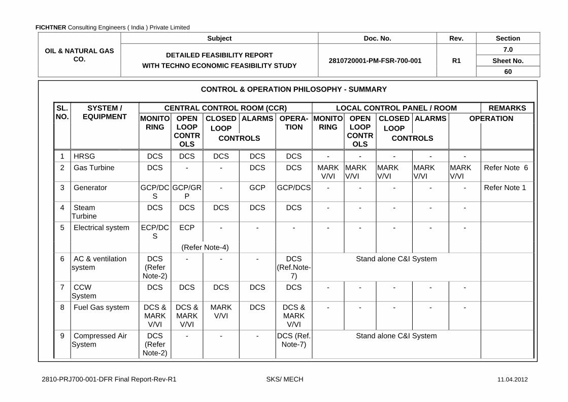
FICHTNER Consulting Engineers ( India ) Private Limited
OIL & NATURAL GAS CO.
Subject Doc. No. Rev. Section
DETAILED FEASIBILITY REPORT
WITH TECHNO ECONOMIC FEASIBILITY STUDY 2810720001-PM-FSR-700-001 R1
7.0
Sheet No.
60
2810-PRJ700-001-DFR Final Report-Rev-R1 SKS/ MECH 11.04.2012
CONTROL & OPERATION PHILOSOPHY - SUMMARY SL. NO.
SYSTEM / EQUIPMENT
CENTRAL CONTROL ROOM (CCR) LOCAL CONTROL PANEL / ROOM REMARKS
MONITORING
OPEN LOOP
CONTROLS
CLOSED ALARMS OPERA- TION
MONITORING
OPEN LOOP
CONTROLS
CLOSED ALARMS OPERATION LOOP LOOP
CONTROLS CONTROLS
1 HRSG DCS DCS DCS DCS DCS - - - - -
2 Gas Turbine DCS - - DCS DCS MARK V/VI
MARK V/VI
MARK V/VI
MARK V/VI
MARK V/VI
Refer Note 6
3 Generator GCP/DCS
GCP/GRP
- GCP GCP/DCS - - - - - Refer Note 1
4 Steam Turbine
DCS DCS DCS DCS DCS - - - - -
5 Electrical system ECP/DCS
ECP - - - - - - - -
(Refer Note-4)
6 AC & ventilation system
DCS (Refer
Note-2)
- - - DCS (Ref.Note-
7)
Stand alone C&I System
7 CCW System
DCS DCS DCS DCS DCS - - - - -
8 Fuel Gas system DCS & MARK V/VI
DCS & MARK V/VI
MARK V/VI
DCS DCS & MARK V/VI
- - - - -
9 Compressed Air System
DCS (Refer
Note-2)
- - - DCS (Ref. Note-7)
Stand alone C&I System

FICHTNER Consulting Engineers ( India ) Private Limited
OIL & NATURAL GAS CO.
Subject Doc. No. Rev. Section
DETAILED FEASIBILITY REPORT
WITH TECHNO ECONOMIC FEASIBILITY STUDY 2810720001-PM-FSR-700-001 R1
7.0
Sheet No.
61
2810-PRJ700-001-DFR Final Report-Rev-R1 SKS/ MECH 11.04.2012
Note :
1 All generator control & operation shall be implemented in GCP. However it shall be possible to synchronise the machine from DCS/CRT
2 In DCS Monitoring of critical parameters is envisaged & these parameters shall be hardwired.
3 Main fire alarm/Indication panel will be located in CCR and section alarm / indication panel will be located in the field as required.
4 All switchyard equipment control and operation shall be implemented in ECP system which shall also be monitored from DCS. However it shall be possible to synchronise the 11/66 KV in coming line breaker from DCS-VDU
5 PLC is interfaced with DCS through serial link using modbus protocol for status monitoring only.
6 GT control system (Mark V, located at CCR) is interfaced with DCS through a redundant serial link
7 Start/Stop command issued from DCS Operator station
8 critical drives are controlled from DCS & other drives from LCP
ABBREVIATIONS USED
PLC Programmable Logic Controller
VDU Video Display Unit Mark V Proprietary of GT Vendor
DCS Distributed Control system (Procontrol P)
GCP Generator Control Panel CCR Central Control Room
C&I Control & Instrumentation
GRP Generator Relay Panel CCW Circulating Cooling Water System
AC Air conditioning PRDS Pressure Reducing and Desuperheating station
ACW Auxiliary Cooling Water System
ST Steam Turbine ECP Electrical Control panel
FICHTNER Consulting Engineers ( India ) Private Limited
OIL & NATURAL GAS CO.
Subject Doc. No. Rev. Section
DETAILED FEASIBILITY REPORT WITH TECHNO ECONOMIC
FEASIBILITY STUDY 2810720001-PM-FSR-700-001 R1
8.0
Sheet No.
1
2810-PRJ700-001-DFR Final Report-Rev-R1 SKS / MECH 11.04.2012
FO
RM
T9-
P R
EV
-B (
MU
M)
SECTION - 8.0
ENVIRONMENTAL ASPECTS

FICHTNER Consulting Engineers ( India ) Private Limited
OIL & NATURAL GAS CO.
Subject Doc. No. Rev. Section
DETAILED FEASIBILITY REPORT WITH TECHNO ECONOMIC
FEASIBILITY STUDY 2810720001-PM-FSR-700-001 R1
8.0
Sheet No.
2
2810-PRJ700-001-DFR Final Report-Rev-R1 SKS / MECH 11.04.2012
FO
RM
T9-
P R
EV
-B (
MU
M)
SECTION - 8.0
ENVIRONMENTAL ASPECTS
CONTENTS
CLAUSE NO. DESCRIPTION SHEET NO.
8.1 INTRODUCTION 3
8.2 AIR POLLUTION 3

FICHTNER Consulting Engineers ( India ) Private Limited
OIL & NATURAL GAS CO.
Subject Doc. No. Rev. Section
DETAILED FEASIBILITY REPORT WITH TECHNO ECONOMIC
FEASIBILITY STUDY 2810720001-PM-FSR-700-001 R1
8.0
Sheet No.
3
2810-PRJ700-001-DFR Final Report-Rev-R1 SKS / MECH 11.04.2012
FO
RM
T9-
P R
EV
-B (
MU
M)
SECTION - 8.0
ENVIRONMENTAL ASPECTS
8.1 INTRODUCTION 8.1.1 Natural gas based combined cycle power plant as compared to combined cycle
plants using liquid fuels is environmentally compatible owing to nil sulphur content in the fuel. Coal based power plant of similar capacity will pollute the atmosphere more than natural gas based combined cycle power plant. In case of conventional combined cycle power plants, fugitive dust emissions and release of effluents will be significantly lower due to the absence of coal and ash handling plants associated with ash disposal areas for solid waste disposal.
8.1.2.2 The CCPP typically has the following broad areas of concern in regard to
environmental issues:
- Air pollution
- Water pollution
- Thermal pollution
- Noise abatement
- Post operational monitoring programme
8.2 AIR POLLUTION 8.2.1 Particulate Matter Emission Natural gas as proposed for the CCPP as main fuel is a clean fuel. Hence, there
will not be any emission of particulate matter in the flue gas coming out of main or bypass stacks both in the combined cycle and simple cycle modes.
8.2.2 Sulphur Dioxide (SO2) Emission Sulphur present in the main fuel Natural gas is very negligible and hence sulphur
dioxide will not be emitted in the flue gas. The main stack height has been fixed as 35 M and bypass stack height is fixed as 30 M as per Pollution Control Boards guidelines and ambient air quality standards.
8.2.3 NOx Emission The only pollutant in the flue gas would be oxides of Nitrogen (NOx). The proposed
gas turbine will have dry low NOx combustors or with water injection. NOx for this project will be limited to the pollution control stipulation of 50 ppmvd at 15% O2 .

FICHTNER Consulting Engineers ( India ) Private Limited
OIL & NATURAL GAS CO.
Subject Doc. No. Rev. Section
DETAILED FEASIBILITY REPORT WITH TECHNO ECONOMIC
FEASIBILITY STUDY 2810720001-PM-FSR-700-001 R1
8.0
Sheet No.
4
2810-PRJ700-001-DFR Final Report-Rev-R1 SKS / MECH 11.04.2012
FO
RM
T9-
P R
EV
-B (
MU
M)
8.2.4 Water Pollution 8.2.4.1 The waste collection and treatment system receives, segregates, and transfers all
plant process and liquid waste streams for plant water management and ensures conformance to the statutory government guidelines prevailing in the state.
8.2.4.2 The description of Effluent collection and disposal system has been given in
Section 7.4.19. 8.2.5 Noise Criteria 8.2.5.1 The noise criteria shall conform to the permissible noise levels of IS:3483. 8.2.5.2 Noises from turbines, fans, centrifugal pumps etc. shall be kept below the
permissible level of 85 dBA at a distance of 1 m from the equipment and 1.5 m from the ground during steady state operation by proper design and selection. Whenever noise levels are higher, they shall be reduced by providing suitable acoustic treatment viz acoustic enclosure etc.
8.2.5.3 Noise from piping and accessories such as HP steam reducing valves, turbulent
flow of steam and feed water are generally below the permissible level of 85 dBA and do not require any acoustic insulation or other noise reducing provision. However for intermittent type noise sources like safety valves, start-up steam vents, inlet of the bypass stack, etc. adequate noise attenuators shall be provided.
8.2.5.4 Suitable measures shall also be taken to limit the plant boundary noise level to less
than 55 dBA during day time and 45 dBA during night time. 8.2.6 Thermal Pollution HRSG is basically installed at the Gas turbine exhaust end to recover substantial
amount of heat from the Gas turbine exhaust gases which will enable reduction of the temperature of the exhaust gases to an acceptable lower values, thereby reducing thermal heat into the atmosphere.
8.2.7 Post Operational Monitoring Programme 8.2.7.1 Regular monitoring of pollutants in different environmental disciplines such as air,
water etc. will be undertaken during the post-operational phase of the plant. Monitoring locations will be finalized in consultation with the State Pollution Control Board. The CCPP will be equipped with environmental monitoring programme supported by all necessary instruments/equipment and trained/qualified manpower for ensuring effective monitoring of the ambient air as well as stack gas quality to ensure that the quality of effluents is maintained within the permissible levels. The bypass stack and the main stack of the heat recovery steam generator shall be provided with suitable instruments to monitor the flue gas quality.
8.2.7.2 The quality of the blow down water from the heat recovery steam generator drums
and the other water effluents from the plant shall be periodically analyzed on a weekly basis to ensure that effluents are maintained within the permissible levels of

FICHTNER Consulting Engineers ( India ) Private Limited
OIL & NATURAL GAS CO.
Subject Doc. No. Rev. Section
DETAILED FEASIBILITY REPORT WITH TECHNO ECONOMIC
FEASIBILITY STUDY 2810720001-PM-FSR-700-001 R1
8.0
Sheet No.
5
2810-PRJ700-001-DFR Final Report-Rev-R1 SKS / MECH 11.04.2012
FO
RM
T9-
P R
EV
-B (
MU
M)
the Minimum National Standards (MINAS) and the State and Central Pollution Control Boards regulations.
8.2.8 Impact of Pollution / Environmental Disturbances The CCPP will require less land area as compared to a similar capacity
conventional thermal power plant. As natural gas is a clean fuel, NOx emission will be minimum and there will be negligible SO2 and no particulate matter emissions. The water effluents will be treated in the existing effluent treatment plant. Adverse impact on either air or water quality in and around the CCPP site is not anticipated.

FICHTNER Consulting Engineers ( India ) Private Limited
OIL & NATURAL GAS CO.
Subject Doc. No. Rev. Section
DETAILED FEASIBILITY REPORT WITH TECHNO ECONOMIC
FEASIBILITY STUDY 2810720001-PM-FSR-700-001 R1
9.0
Sheet No.
1
2810-PRJ700-001-DFR Final Report-Rev-R1 SKS / MECH 11.04.2012
FO
RM
T9-
P R
EV
-B (
MU
M)
SECTION – 9.0
ORGANIZATIONAL SETUP FOR PLANT OPERATION AND MAINTENANCE

FICHTNER Consulting Engineers ( India ) Private Limited
OIL & NATURAL GAS CO.
Subject Doc. No. Rev. Section
DETAILED FEASIBILITY REPORT WITH TECHNO ECONOMIC
FEASIBILITY STUDY 2810720001-PM-FSR-700-001 R1
9.0
Sheet No.
2
2810-PRJ700-001-DFR Final Report-Rev-R1 SKS / MECH 11.04.2012
FO
RM
T9-
P R
EV
-B (
MU
M)
SECTION – 9.0
ORGANIZATIONAL SETUP FOR PLANT OPERATION AND MAINTENANCE
CONTENTS
CLAUSE NO. DESCRIPTION SHEET NO.
9.1 INTRODUCTION 3
9.2 PLANT OPERATION 3
9.3 PLANT MAINTENANCE 3
9.4 MECHANICAL MAINTENANCE 3
9.5 ELECTRICAL AND C&I MAINTENANCE 3
9.6 SAFETY 3
9.7 PERFORMANCE MONITORING 4
9.8 OTHERS 4
9.9 TRAINING OF PERSONNEL 4

FICHTNER Consulting Engineers ( India ) Private Limited
OIL & NATURAL GAS CO.
Subject Doc. No. Rev. Section
DETAILED FEASIBILITY REPORT WITH TECHNO ECONOMIC
FEASIBILITY STUDY 2810720001-PM-FSR-700-001 R1
9.0
Sheet No.
3
2810-PRJ700-001-DFR Final Report-Rev-R1 SKS / MECH 11.04.2012
FO
RM
T9-
P R
EV
-B (
MU
M)
SECTION – 9.0
ORGANIZATIONAL SETUP FOR PLANT OPERATION AND MAINTENANCE
9.1 INTRODUCTION The proposed CCPP will be a part of the existing power plant .The new CCPP will
have adequate degree of automation requiring a minimum number of personnel as the services of the existing O &M staff can be extended for the new CCPP. Appropriate number of suitable technical and administrative personnel at the plant site will be under the disciplinary control of the Power plant manager of the existing cogen plant as well new CCPP. The proposed O&M chart is enclosed herewith.
9.2 PLANT OPERATION This plant operation wing will be headed by Operations Manager and will be
supported by experienced engineers for manning round the clock plant operation in shifts. The Plant Shift Manager will be assisted by Plant Control Engineer and Operating engineers for the day to day operation of the plant.
9.3 PLANT MAINTENANCE The plant maintenance wing will be headed by Maintenance Manager, experienced
maintenance engineers responsible for Mechanical, Electrical, Control & Instrumentation maintenance respectively; and will be assisted by Mechanical, Electrical and C&I maintenance staff with extensive experience in the similar capacity combined cycle power plant.
9.4 MECHANICAL MAINTENANCE For mechanical maintenance of the CCPP adequately experienced mechanical
maintenance engineers supported by skilled personnel and semi-skilled personnel of various categories have been envisaged as a part of Mechanical Maintenance crew.
9.5 ELECTRICAL AND C&I MAINTENANCE For Electrical and C&I maintenance of CCPP, experienced Electrical and C&I
maintenance engineers supported by skilled and semi-skilled personnel of various categories have been envisaged as a part of Electrical & C&I Maintenance crew.
9.6 SAFETY This group will be headed by a Safety & Fire Manager and will be incharge for the
safety and security of the plant.
FICHTNER Consulting Engineers ( India ) Private Limited
OIL & NATURAL GAS CO.
Subject Doc. No. Rev. Section
DETAILED FEASIBILITY REPORT WITH TECHNO ECONOMIC
FEASIBILITY STUDY 2810720001-PM-FSR-700-001 R1
9.0
Sheet No.
4
2810-PRJ700-001-DFR Final Report-Rev-R1 SKS / MECH 11.04.2012
FO
RM
T9-
P R
EV
-B (
MU
M)
9.7 PERFORMANCE MONITORING The Operating Engineers will be involved in monitoring the performance of the
CCPP, and will record power generation, fuel consumption, Plant load factor, operational efficiency etc. They will analyze CCPP performance and report to Plant Manager, their finding along with suggested means for the plant betterment.
9.8 OTHERS In addition to above, the CCPP organization will have a team headed by Manager –
Finance & Administration for office administration, finance, accounts, personnel, health etc. and a team headed by Materials & Contracts Manager for procurement related activities.
9.9 TRAINING OF PERSONNEL Successful plant operation and maintenance depends upon the efficiency and
performance of its personnel. To achieve high degree of efficiency in plant management and operation, it is desirable to train up personnel for the operation of the sets. The training schemes shall include:
- General theoretical training on power station operation and maintenance.
- Actual in-plant training in similar power stations elsewhere.
- Training at supplier’s works/plant
- Training during erection of equipment at site by the supplier.

FICHTNER Consulting Engineers ( India ) Private Limited
OIL & NATURAL GAS CO.
Subject Doc. No. Rev. Section
DETAILED FEASIBILITY REPORT
WITH TECHNO ECONOMIC FEASIBILITY STUDY 2810720001-PM-FSR-700-001 R1
9.0
Sheet No.
5
2810-PRJ700-001-DFR Final Report-Rev-R1 SKS / MECH 11.04.2012
eneral Manager
OperationsManager [1]
Safety & Fire Manager [*]
ManagerFinance & Administration [*]
Manager [*]
ManagerMaintenance [1]
Materials & Contract Manager [*]
PCE[4]
Chief Chemist [*]
AE[6]
JE [3]
OfficeSecretary [*]
AccountsOfficer [*]
DocumentClerk [1]
System Administrator [*]
MaterialsOfficer [*]
WarehouseSupervisor [*]
ME Mechanical [1]
MEC & I [1]
ME Electrical [1]
AEMech [2]
AEElec [2]
AEC & I [1]
LEGENDS
AE : ASSISTANT ENGINEER JE : JUNIOR ENGINEER ME : MAINTENANCE ENGINEER PE : BOILER PROFICIENCY ENGINEER
PCE : PLANT CONTROL ENGINEER
* : Existing CPP staff to be extended for New CCPP.
PE [3]

FICHTNER Consulting Engineers ( India ) Private Limited
OIL & NATURAL GAS CO.
Subject Doc. No. Rev. Section
DETAILED FEASIBILITY REPORT WITH TECHNO ECONOMIC
FEASIBILITY STUDY 2810720001-PM-FSR-700-001 R1
10.0
Sheet No.
1
2810-PRJ700-001-DFR Final Report-Rev-R1 SKS / MECH 11.04.2012
FO
RM
T9-
P R
EV
-B (
MU
M)
SECTION – 10.0
PROJECT IMPLEMENTATION

FICHTNER Consulting Engineers ( India ) Private Limited
OIL & NATURAL GAS CO.
Subject Doc. No. Rev. Section
DETAILED FEASIBILITY REPORT WITH TECHNO ECONOMIC
FEASIBILITY STUDY 2810720001-PM-FSR-700-001 R1
10.0
Sheet No.
2
2810-PRJ700-001-DFR Final Report-Rev-R1 SKS / MECH 11.04.2012
FO
RM
T9-
P R
EV
-B (
MU
M)
SECTION – 10.0
PROJECT IMPLEMENTATION
CONTENTS
CLAUSE NO. DESCRIPTION SHEET NO.
10.1 PROJECT SCHEDULE 3
10.2 PROCUREMENT PROCEDURE 3
10.3 CONSTRUCTION FACILITIES 3

FICHTNER Consulting Engineers ( India ) Private Limited
OIL & NATURAL GAS CO.
Subject Doc. No. Rev. Section
DETAILED FEASIBILITY REPORT WITH TECHNO ECONOMIC
FEASIBILITY STUDY 2810720001-PM-FSR-700-001 R1
10.0
Sheet No.
3
2810-PRJ700-001-DFR Final Report-Rev-R1 SKS / MECH 11.04.2012
FO
RM
T9-
P R
EV
-B (
MU
M)
SECTION – 10.0
PROJECT IMPLEMENTATION
10.1 PROJECT SCHEDULE 10.1.1 Project completion period has a significant influence on the overall project cost in
terms of the interest paid during construction. Hence, shortest possible project schedule will be adopted along with effective project implementation methods to ensure completion of Project in time. The project will be implemented on an Engineering, Procurement and Construction (EPC) basis.
10.1.2 For the subject CCPP project, it is realistic to consider a project completion time of
18 months for simple cycle of gas turbine and 24 months for combined cycle completion from the date of notice to proceed. A bar chart has been appended herewith indicating the duration of all major activities. It may be observed that the critical long delivery items are GT, ST, HRSG, Generator Transformers, Switchyard
Transformers & C&I package. Delivery period for the main plant equipment given by domestic / foreign suppliers varies depending on equipment rating, order in hard, availability of ex-stock components etc. While finalizing the order for the EPC contract including main plant equipment, due weightage shall be given for the delivery period of the above cited equipment / systems.
10.1.3 Procurement of all auxiliary equipment and civil works will have sufficient floats and
are not expected to come in the critical path if planned and implemented properly. 10.1.4 Leveling at site will be taken on priority. Foundation of major buildings & structures
is scheduled to be completed to suit the erection of main plant equipment. Superstructure of ST building and control building is scheduled to be completed simultaneously. Erection of all other auxiliary systems such as fire water, electrical and C&I are scheduled to be completed well in advance such that sufficient time would be available for trial run and checking the performance of various parameters.
10.1.5 A detailed project schedule has been enclosed as Annex - 2 10.2 PROCUREMENT PROCEDURE It is envisaged that the simple cycle and the combined cycle will be commissioned
as per the schedule indicated above. It is imperative that the whole procurement would be packaged in such a manner that will lead to shortest gestation period and firm guarantees on performance and completion schedule will be obtained to make investment remunerative.
10.3 CONSTRUCTION FACILITIES 10.3.1 Adequate construction facilities such as offices, stores, sheds etc will be created.
These facilities will be created keeping in view the area required for permanent facilities.

FICHTNER Consulting Engineers ( India ) Private Limited
OIL & NATURAL GAS CO.
Subject Doc. No. Rev. Section
DETAILED FEASIBILITY REPORT WITH TECHNO ECONOMIC
FEASIBILITY STUDY 2810720001-PM-FSR-700-001 R1
10.0
Sheet No.
4
2810-PRJ700-001-DFR Final Report-Rev-R1 SKS / MECH 11.04.2012
FO
RM
T9-
P R
EV
-B (
MU
M)
10.3.2 Road The access roads will be built-up at the initial stage. 10.3.3 Construction Office and Stores 10.3.3.1 For accommodating the construction personnel and Contractors, Construction
offices with adequate area will be constructed. 10.3.3.2 To protect delicate and sophisticated equipments/instruments and tools and tackles
a covered storage of adequate area will be constructed on permanent basis. In addition to this, temporary stores will be constructed to the extent required.
10.3.4 Construction Water Required construction water shall be obtained from existing system available at site. 10.3.5 Construction Power Construction power shall be made available from nearby existing system available
at site. 10.3.6 Construction Equipment 10.3.6.1 Adequate construction equipment along with adequate quantity of spares will be
made available at site. The equipment shall include, but not limited to bull dozer, road roller, truck mounted cranes, tractor trailers, truck trailers, winches, pumps, air compressors, D.G. sets, welding generators, etc.

FICHTNER Consulting Engineers ( India ) Private Limited
OIL & NATURAL GAS CO.
Subject Doc. No. Rev. Section
DETAILED FEASIBILITY REPORT WITH TECHNO ECONOMIC
FEASIBILITY STUDY 2810720001-PM-FSR-700-001 R1
11.0
Sheet No.
1
2810-PRJ700-001-DFR Final Report-Rev-R1 SKS / MECH 11.04.2012
FO
RM
T9-
P R
EV
-B (
MU
M)
SECTION – 11.0
PERMITS AND CLEARANCES

FICHTNER Consulting Engineers ( India ) Private Limited
OIL & NATURAL GAS CO.
Subject Doc. No. Rev. Section
DETAILED FEASIBILITY REPORT WITH TECHNO ECONOMIC
FEASIBILITY STUDY 2810720001-PM-FSR-700-001 R1
11.0
Sheet No.
2
2810-PRJ700-001-DFR Final Report-Rev-R1 SKS / MECH 11.04.2012
FO
RM
T9-
P R
EV
-B (
MU
M)
SECTION – 11.0
PERMITS AND CLEARANCES
CONTENTS
CLAUSE NO. DESCRIPTION SHEET NO.
11.1 PERMITS AND CLEARANCES BEFORE FINANCIAL CLOSURE 3
11.2 PERMITS AND LICENSES REQUIRED BEFORE START OF CONSTRUCTION 4
11.3 PERMITS AND CLEARANCE DURING CONSTRUCTION 5
11.4 OTHERS 5
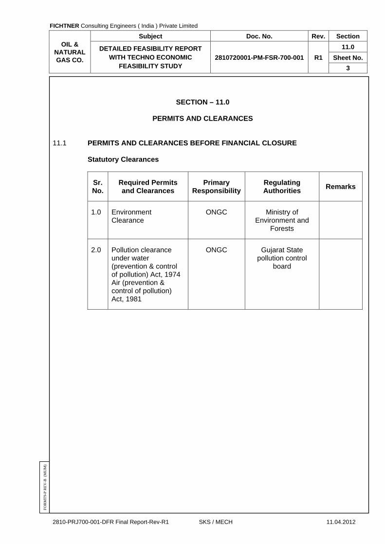
FICHTNER Consulting Engineers ( India ) Private Limited
OIL & NATURAL GAS CO.
Subject Doc. No. Rev. Section
DETAILED FEASIBILITY REPORT WITH TECHNO ECONOMIC
FEASIBILITY STUDY 2810720001-PM-FSR-700-001 R1
11.0
Sheet No.
3
2810-PRJ700-001-DFR Final Report-Rev-R1 SKS / MECH 11.04.2012
FO
RM
T9-
P R
EV
-B (
MU
M)
SECTION – 11.0
PERMITS AND CLEARANCES 11.1 PERMITS AND CLEARANCES BEFORE FINANCIAL CLOSURE Statutory Clearances
Sr. No.
Required Permits and Clearances
Primary Responsibility
Regulating Authorities
Remarks
1.0 Environment Clearance
ONGC Ministry of Environment and
Forests
2.0 Pollution clearance under water (prevention & control of pollution) Act, 1974 Air (prevention & control of pollution) Act, 1981
ONGC Gujarat State pollution control
board

FICHTNER Consulting Engineers ( India ) Private Limited
OIL & NATURAL GAS CO.
Subject Doc. No. Rev. Section
DETAILED FEASIBILITY REPORT WITH TECHNO ECONOMIC
FEASIBILITY STUDY 2810720001-PM-FSR-700-001 R1
11.0
Sheet No.
4
2810-PRJ700-001-DFR Final Report-Rev-R1 SKS / MECH 11.04.2012
FO
RM
T9-
P R
EV
-B (
MU
M)
11.2 PERMITS AND LICENSES REQUIRED BEFORE START OF CONSTRUCTION
Sr. No.
Required permits and Clearances
Primary Responsibility
Regulating Authorities
Remarks
1.0 Approval for temporary construction power facility within plant area
EPC - Contractor
Chief electrical inspectorate
Before start of construction
2.0 License from labour commissioner for construction labours pursuant to Section-7 of the contract labour (regulation & abolition) Act, 1970
EPC – Contractor
Labour commissioner, Government of
Gujarat
Before start of construction
3.0 Registration of workers pursuant to Section-2A of employees state insurance Act, 1684, or exemption to be claimed if other group insurance is taken (for contractors personnel)
EPC - Contractor
Labour commissioner, Government of
Gujarat
Before start of construction
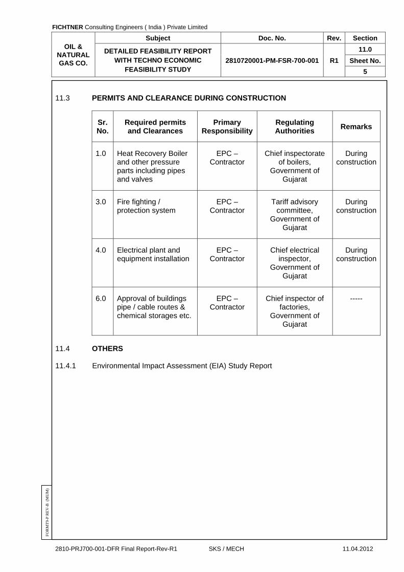
FICHTNER Consulting Engineers ( India ) Private Limited
OIL & NATURAL GAS CO.
Subject Doc. No. Rev. Section
DETAILED FEASIBILITY REPORT WITH TECHNO ECONOMIC
FEASIBILITY STUDY 2810720001-PM-FSR-700-001 R1
11.0
Sheet No.
5
2810-PRJ700-001-DFR Final Report-Rev-R1 SKS / MECH 11.04.2012
FO
RM
T9-
P R
EV
-B (
MU
M)
11.3 PERMITS AND CLEARANCE DURING CONSTRUCTION
Sr. No.
Required permits and Clearances
Primary Responsibility
Regulating Authorities
Remarks
1.0 Heat Recovery Boiler and other pressure parts including pipes and valves
EPC – Contractor
Chief inspectorate of boilers,
Government of Gujarat
During construction
3.0 Fire fighting / protection system
EPC – Contractor
Tariff advisory committee,
Government of Gujarat
During construction
4.0 Electrical plant and equipment installation
EPC – Contractor
Chief electrical inspector,
Government of Gujarat
During construction
6.0 Approval of buildings pipe / cable routes & chemical storages etc.
EPC – Contractor
Chief inspector of factories,
Government of Gujarat
-----
11.4 OTHERS 11.4.1 Environmental Impact Assessment (EIA) Study Report

FICHTNER Consulting Engineers ( India ) Private Limited
OIL & NATURAL GAS CO.
Subject Doc. No. Rev. Section
DETAILED FEASIBILITY REPORT WITH TECHNO ECONOMIC
FEASIBILITY STUDY 2810720001-PM-FSR-700-001 R1
12.0
Sheet No.
1
2810-PRJ700-001-DFR Final Report-Rev-R1 SKS / MECH 11.04.2012
FO
RM
T9-
P R
EV
-B (
MU
M)
SECTION – 12.0
COST ESTIMATE

FICHTNER Consulting Engineers ( India ) Private Limited
OIL & NATURAL GAS CO.
Subject Doc. No. Rev. Section
DETAILED FEASIBILITY REPORT WITH TECHNO ECONOMIC
FEASIBILITY STUDY 2810720001-PM-FSR-700-001 R1
12.0
Sheet No.
2
2810-PRJ700-001-DFR Final Report-Rev-R1 SKS / MECH 11.04.2012
FO
RM
T9-
P R
EV
-B (
MU
M)
SECTION – 12.0
COST ESTIMATE
CONTENTS
CLAUSE NO. DESCRIPTION SHEET NO.
12.1 BASIS OF COST ESTIMATE 3
12.2 CAPITAL COST 3
12.3 ESTIMATED PROJECT COST 4
12.4 SUMMARY OF ESTIMATED PROJECT COST 7
12.5 ESTIMATED COST OF POWER GENERATION (WITHOUT LOAN) 8
12.6 ESTIMATED COST OF POWER GENERATION
CONSIDERING 70% LOAN 10

FICHTNER Consulting Engineers ( India ) Private Limited
OIL & NATURAL GAS CO.
Subject Doc. No. Rev. Section
DETAILED FEASIBILITY REPORT WITH TECHNO ECONOMIC
FEASIBILITY STUDY 2810720001-PM-FSR-700-001 R1
12.0
Sheet No.
3
2810-PRJ700-001-DFR Final Report-Rev-R1 SKS / MECH 11.04.2012
FO
RM
T9-
P R
EV
-B (
MU
M)
SECTION – 12.0
COST ESTIMATE
12.1 BASIS OF COST ESTIMATE 12.1.1 The installed cost of the power plant has been estimated taking into
account the cost of civil, structural & architectural works, plant and machinery, electrical & instrumentation works, transportation, installation, testing and commissioning. The plant cost estimate has been worked on the following basis.
12.1.2 The total estimated cost for these packages indicated is the ex-works. The total estimated costs of gas turbine generator, heat recovery steam generator, steam turbine generator and their auxiliaries, water cooled condenser, water treatment plant, cooling water pumps etc. are based on budgetary quotes obtained for this project or for similar capacity projects with necessary escalation. Other electrical, control & instrumentation and mechanical equipment are based on the prices available in consultant’s data bank. However, for some systems and equipment, the estimated costs are based on either cost particulars available for similar equipment or estimated values.
12.1.3 The cost of spare parts has been taken as 2% of equipment cost ex-works for mechanical and electrical equipment. For control & instrumentation, it has been already included in the price.
12.1.5 The Excise duty has been considered at the applicable rates as per the prevailing Central Excise Tariff rates on the ex-works cost.
12.1.6 The Sales Tax has been considered as 2% on the total supply cost of mechanical and electrical equipment.
12.1.7 Packaging & forwarding has been considered as 2% of ex-works price of the equipment.
12.1.8 Contingencies are provided at 2.0% of the installed cost of plant and equipment, civil works, electrical and instrumentation.
12.2 CAPITAL COST 12.2.1 The summary of cost estimate for installing the power plant is furnished in
the Table-12.4 and estimated project cost estimate is given in Table – 12.3. Estimated cost of power generation is detailed in the Table – 12.5
12.2.2 The plant installed cost is estimated to be around Rs. 249 Crores. The above cost includes interest during construction, margin money for working capital .

FICHTNER Consulting Engineers ( India ) Private Limited
OIL & NATURAL GAS CO.
Subject Doc. No. Rev. Section
DETAILED FEASIBILITY REPORT WITH TECHNO ECONOMIC
FEASIBILITY STUDY 2810720001-PM-FSR-700-001 R1
13.0
Sheet No.
1
2810-PRJ700-001-DFR Final Report-Rev-R1 SKS / MECH 11.04.2012
FO
RM
T9-
P R
EV
-B (
MU
M)
SECTION – 13.0
MARKETING OF STANDBY CAPACITY

FICHTNER Consulting Engineers ( India ) Private Limited
OIL & NATURAL GAS CO.
Subject Doc. No. Rev. Section
DETAILED FEASIBILITY REPORT WITH TECHNO ECONOMIC
FEASIBILITY STUDY 2810720001-PM-FSR-700-001 R1
13.0
Sheet No.
2
2810-PRJ700-001-DFR Final Report-Rev-R1 SKS / MECH 11.04.2012
FO
RM
T9-
P R
EV
-B (
MU
M)
SECTION – 13.0
MARKETING OF STANDBY CAPACITY
CONTENTS
CLAUSE NO. DESCRIPTION SHEET NO.
13.1 INTRODUCTION 3
13.2 TARIFF FOR EXPORT OF POWER 3
13.3 DETAILS OF THE INTERSTATE ELECTRICITY TRADING AVAILABLE FROM CERC WEB SITE 3
13.4 CONCLUSION 6

FICHTNER Consulting Engineers ( India ) Private Limited
OIL & NATURAL GAS CO.
Subject Doc. No. Rev. Section
DETAILED FEASIBILITY REPORT WITH TECHNO ECONOMIC
FEASIBILITY STUDY 2810720001-PM-FSR-700-001 R1
13.0
Sheet No.
3
2810-PRJ700-001-DFR Final Report-Rev-R1 SKS / MECH 11.04.2012
FO
RM
T9-
P R
EV
-B (
MU
M)
SECTION – 13.0
MARKETING OF STANDBY CAPACITY
13.1 INTRODUCTION 13.1.1 The excess power from the existing cogen plant at ONGC Hazira and the power
generated from the proposed standby power generating unit is available for export .Present Power requirement of ONGC is around 30 MW . With the existing cogen plant running at its rated capacity, about 30 MW of power is being exported to GETCO after meeting the ONGC Hazira complex load of around 30mw. After the installation of new standby power plant an additional power of around 50 MW will be available for export. Thus a total power of around 80 MW will be available for export after commissioning of Stand by power plant. As per the open access this excess power can be sold to external consumers via power trading mechanism or to state electricity boards. There are variations in the export tariff rates for excess power sale. The power sale rate depends on the demand / supply situation during the year.
13.2 TARIFF FOR EXPORT OF POWER The excess power available can be sold through various power trading companies.
The details of the Interstate trading of electricity during 4 different quarters of the year 2006-2007 (Oct. 2006 to Sept. 2008) which is available from the CERC web site is as given below:
13.3 DETAILS OF THE INTERSTATE ELECTRICITY TRADING AVAILABLE FROM
CERC WEB SITE 13.3.1 Inter-State Trading in Electricity during October – December 2006
Sl. No.
Name of the Trading Licensee
Volume of Electricity
Traded (MUs)
% to the Total Volume Traded
Weighted Average Purchase Price
(Rs./kwh)
1. PTC India Ltd. 1235.92 30.13 4.54
2. NTPC Vidyut Vyapar Nigam Ltd.
476.43 11.61 4.81
3. Tata Power Trading Company
406.66 9.91 5.37
4. Reliance Energy Trading Ltd.
322.32 7.86 4.04
5. Adani Exports Ltd. 916.99 22.35 5.35

FICHTNER Consulting Engineers ( India ) Private Limited
OIL & NATURAL GAS CO.
Subject Doc. No. Rev. Section
DETAILED FEASIBILITY REPORT WITH TECHNO ECONOMIC
FEASIBILITY STUDY 2810720001-PM-FSR-700-001 R1
13.0
Sheet No.
4
2810-PRJ700-001-DFR Final Report-Rev-R1 SKS / MECH 11.04.2012
FO
RM
T9-
P R
EV
-B (
MU
M)
Sl. No.
Name of the Trading Licensee
Volume of Electricity
Traded (MUs)
% to the Total Volume Traded
Weighted Average Purchase Price
(Rs./kwh)
6. Subash Kabini Power Corporation Ltd.
Nil
7. Lanco Electric Utility Ltd. 274.11 6.68 4.47
8. JSW Power Trading Company Ltd.
429.41 10.47 4.56
9. Karamchand Thapar and Bros Ltd.
40.86 1.00 5.07
Total 4102.39 100.00 4.80
13.3.2 Inter-State Trading in Electricity during January - March 2007
Sl. No.
Name of the Trading Licensee
Volume of Electricity
Traded (MUs)
% to the Total Volume Traded
Weighted Average Purchase Price
(Rs./kwh)
1. PTC India Ltd. 969.69 32.12 4.54
2. NTPC Vidyut Vyapar Nigam Ltd.
680.61 22.55 3.90
3. Tata Power Trading Company
339.91 11.26 5.27
4. Reliance Energy Trading Ltd.
96.06 3.18 4.56
5. Adani Exports Ltd. 308.53 10.22 5.46
6. Subash Kabini Power Corporation Ltd.
Nil Nil Nil
7. Lanco Electric Utility Ltd. 124.09 4.11 4.56
8. JSW Power Trading Company Ltd.
460.18 15.24 4.90
9. Karamchand Thapar and Bros Ltd.
39.66 1.31 5.95
Total 3018.72 100.00 4.65
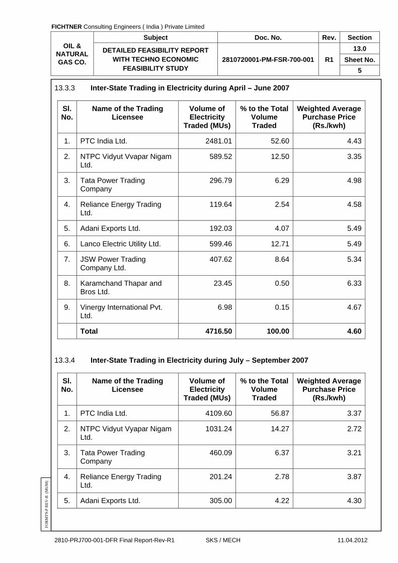
FICHTNER Consulting Engineers ( India ) Private Limited
OIL & NATURAL GAS CO.
Subject Doc. No. Rev. Section
DETAILED FEASIBILITY REPORT WITH TECHNO ECONOMIC
FEASIBILITY STUDY 2810720001-PM-FSR-700-001 R1
13.0
Sheet No.
5
2810-PRJ700-001-DFR Final Report-Rev-R1 SKS / MECH 11.04.2012
FO
RM
T9-
P R
EV
-B (
MU
M)
13.3.3 Inter-State Trading in Electricity during April – June 2007
Sl. No.
Name of the Trading Licensee
Volume of Electricity
Traded (MUs)
% to the Total Volume Traded
Weighted Average Purchase Price
(Rs./kwh)
1. PTC India Ltd. 2481.01 52.60 4.43
2. NTPC Vidyut Vvapar Nigam Ltd.
589.52 12.50 3.35
3. Tata Power Trading Company
296.79 6.29 4.98
4. Reliance Energy Trading Ltd.
119.64 2.54 4.58
5. Adani Exports Ltd. 192.03 4.07 5.49
6. Lanco Electric Utility Ltd. 599.46 12.71 5.49
7. JSW Power Trading Company Ltd.
407.62 8.64 5.34
8. Karamchand Thapar and Bros Ltd.
23.45 0.50 6.33
9. Vinergy International Pvt. Ltd.
6.98 0.15 4.67
Total 4716.50 100.00 4.60
13.3.4 Inter-State Trading in Electricity during July – September 2007
Sl. No.
Name of the Trading Licensee
Volume of Electricity
Traded (MUs)
% to the Total Volume Traded
Weighted Average Purchase Price
(Rs./kwh)
1. PTC India Ltd. 4109.60 56.87 3.37
2. NTPC Vidyut Vyapar Nigam Ltd.
1031.24 14.27 2.72
3. Tata Power Trading Company
460.09 6.37 3.21
4. Reliance Energy Trading Ltd.
201.24 2.78 3.87
5. Adani Exports Ltd. 305.00 4.22 4.30

FICHTNER Consulting Engineers ( India ) Private Limited
OIL & NATURAL GAS CO.
Subject Doc. No. Rev. Section
DETAILED FEASIBILITY REPORT WITH TECHNO ECONOMIC
FEASIBILITY STUDY 2810720001-PM-FSR-700-001 R1
13.0
Sheet No.
6
2810-PRJ700-001-DFR Final Report-Rev-R1 SKS / MECH 11.04.2012
FO
RM
T9-
P R
EV
-B (
MU
M)
Sl. No.
Name of the Trading Licensee
Volume of Electricity
Traded (MUs)
% to the Total Volume Traded
Weighted Average Purchase Price
(Rs./kwh)
6. Lanco Electric Utility Ltd. 705.58 9.76 3.08
7. JSW Power Trading Company Ltd.
307.42 4.25 4.08
8. Karamchand Thapar and Bros Ltd.
56.12 0.78 4.09
9. Vinergy International Pvt. Ltd.
46.75 0.65 3.44
10. Visa Power Ltd. 3.46 0.05 3.51
Total 7226.51 100.00 3.33
13.3.5 Summary of Tariff’s
Sl. No.
Description Oct –Dec
2006
Jan - Mar
2007
Apr-June
2007
July-Sept
2007
Average Tariff for the year
1. Weighted Average Purchase Price(Rs./kwh)
4.80 4.65 4.60 3.33 4.345
13.4 CONCLUSION
This weighted average tariff includes the wheeling charges , administrative fees
and other misc. charges as applicable. Power trading companies generally pay tariff 12% less at the point of power injection to account for the wheeling charges, administrative charges and other misc. charges. So projected tariff rate of Rs 3.82 /Kwh for sale of power at the point of injection at ONGC, Hazira complex is achievable. However in case of sale of power to electricity board a lower tariff is expected. Considering the small volume of surplus power available with ONGC, it is expected that sale of power through power trading companies is possible.

FICHTNER Consulting Engineers ( India ) Private Limited
OIL & NATURAL GAS CO.
Subject Doc. No. Rev. Section
DETAILED FEASIBILITY REPORT WITH TECHNO ECONOMIC
FEASIBILITY STUDY 2810720001-PM-FSR-700-001 R1
14.0
Sheet No.
1
2810-PRJ700-001-DFR Final Report-Rev-R1 SKS / MECH 11.04.2012
FO
RM
T9-
P R
EV
-B (
MU
M)
SECTION – 14.0
DRAWINGS

FICHTNER Consulting Engineers ( India ) Private Limited
OIL & NATURAL GAS CO.
Subject Doc. No. Rev. Section
DETAILED FEASIBILITY REPORT WITH TECHNO ECONOMIC
FEASIBILITY STUDY 2810720001-PM-FSR-700-001 R1
14.0
Sheet No.
2
2810-PRJ700-001-DFR Final Report-Rev-R1 SKS / MECH 11.04.2012
FO
RM
T9-
P R
EV
-B (
MU
M)
SECTION – 14.0
DRAWINGS
Sr. No. Description Drawing No.
1. Plot Plan (Option-I) 10-2810720001-G-001
2. Plot Plan (Option-II) 10-2810720001-G-001
3. Symbols and Legends (Equipment & Piping) 10-2810720001-M-002
4. Symbols and Legends (Control & Instruments) 10-2810720001-M-003
5. P & I Diagram – Steam System 10-2810720001-M-004
6. P & I Diagram – LP Feed System 10-2810720001-M-005 (Sheet 1 of 2)
7. P & I Diagram – HP Feed System 10-2810720001-M-005 (Sheet 2 of 2)
8. P & I Diagram – Condensate System 10-2810720001-M-006
9. P & I Diagram – Natural Gas System 10-2810720001-M-007
10. P & I Diagram- cooling water system 10-2810720001-M-010
11. P & I Diagram – HRSG (HP Section) 10-2810720001-M-011 (Sheet 1 of 2)
12. P & I Diagram – HRSG (LP Section) 10-2810720001-M-011 (Sheet 2 of 2)
13. DCS configuration diagram 20-2810720001-I-351
14. Key Single Line Diagram Option-I 00-2810720001-E-201
15. Key Single Line Diagram Option-II 00-2810720001-E-201A
16. Typical protection and metering diagram 30-2810720001-E-202 (Sheet 1 of 2)
17. Typical protection and metering diagram 30-2810720001-E-202 (Sheet 2 of 2)
FICHTNER Consulting Engineers ( India ) Private Limited
OIL & NATURAL GAS CO.
Subject Doc. No. Rev. Section
DETAILED FEASIBILITY REPORT WITH TECHNO ECONOMIC
FEASIBILITY STUDY 2810720001-PM-FSR-700-001 R1
ANNEX-1
Sheet No.
1
2810-PRJ700-001-DFR Final Report-Rev-R1 SKS / MECH 11.04.2012
FO
RM
T9-
P R
EV
-B (
MU
M)
ANNEX – 1
HEAT & MASS BALANCE DIAG4RAM (HMBD)

FICHTNER Consulting Engineers ( India ) Private Limited
OIL & NATURAL GAS CO.
Subject Doc. No. Rev. Section
DETAILED FEASIBILITY REPORT WITH TECHNO ECONOMIC
FEASIBILITY STUDY 2810720001-PM-FSR-700-001 R1
ANNEX-2
Sheet No.
1
2810-PRJ700-001-DFR Final Report-Rev-R1 SKS / MECH 11.04.2012
FO
RM
T9-
P R
EV
-B (
MU
M)
ANNEX – 2
PROJECT BAR CHART

FICHTNER Consulting Engineers ( India ) Private Limited
OIL & NATURAL GAS CO.
Subject Doc. No. Rev. Section
DETAILED FEASIBILITY REPORT WITH TECHNO ECONOMIC
FEASIBILITY STUDY 2810720001-PM-FSR-700-001 R1
ANNEX-3
Sheet No.
1
2810-PRJ700-001-DFR Final Report-Rev-R1 SKS / MECH 11.04.2012
FO
RM
T9-
P R
EV
-B (
MU
M)
ANNEX – 3
FINANCIAL ANALYSIS (WITHOUT LOAN)

FICHTNER Consulting Engineers ( India ) Private Limited
OIL & NATURAL GAS CO.
Subject Doc. No. Rev. Section
DETAILED FEASIBILITY REPORT WITH TECHNO ECONOMIC
FEASIBILITY STUDY 2810720001-PM-FSR-700-001 R1
ANNEX-4
Sheet No.
1
2810-PRJ700-001-DFR Final Report-Rev-R1 SKS / MECH 11.04.2012
FO
RM
T9-
P R
EV
-B (
MU
M)
ANNEX – 4
FINANCIAL ANALYSIS (WITH LOAN)