Social Cohesion and Connectivity: Diffusion Implications of Relational Structure
Upload
khoahuy82Category
view
78download
0
Relational structure
• We can express the structure of a relation by a Tuple, a shorthand notation
• The name of the relation is followed (in parentheses) by the names of the attributes of that relation, e.g.:
• EMPLOYEE1(Emp_ID,Name,Dept,Salary)

Relational keys
• Must be able to store and retrieve a row of data in a relation, based on the data values stored in that row
• A primary key is an attribute (or combination of attributes) that uniquely identifies each row in a relation.
• The primary key in the EMPLOYEE1 relation is EMP_ID (this is why it is underlined) as in:
• EMPLOYEE1(Emp_ID,Name,Dept,Salary)

Composite and Foreign keys
A Composite key is a primary key that consists of more than one attribute.
e.g., the primary key for the relation DEPENDENT would probably consist of the combination Emp-ID and Dependent_Name
A Foreign key is used when we must represent the relationship between two tables and relations
A foreign key is an attribute (possibly composite) in a relation of a database that serves as the primary key of another relation in the same database

Foreign keys
Consider the following relations:
EMPLOYEE1(Emp_ID,Name,Dept_Name,Salary)
DEPARTMENT(Dept_Name,Location,Fax)
The attribute Dept_Name is a foreign key in EMPLOYEE1. It allows the user to associate any employee wit the department they are assigned to.
Some authors show the fact that an attribute is a foreign key by using a dashed underline.
Relational Keys
• Super Key : An attribute (or combination of attributes) that uniquely identifies each entity in a table.
• Candidate Key : A minimal super key. A super key that does not contain a subset of attributes that is itself a super key.
• Primary key : A candidate key selected to uniquely identify all other attribute values in any given row. Cannot contain null entries.
• Secondary Key : An attribute ( or combination of attributes) used strictly for data retrieval.
Removing multivalued attributes from tables
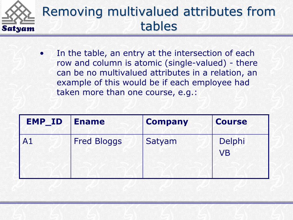
• In the table, an entry at the intersection of each row and column is atomic (single-valued) - there can be no multivalued attributes in a relation, an example of this would be if each employee had taken more than one course, e.g.:
EMP_ID Ename Company Course
A1 Fred Bloggs Satyam Delphi
VB
Removing multivalued attributes from tables
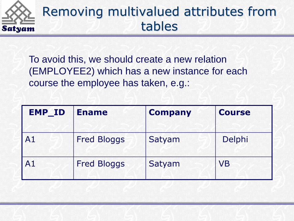
To avoid this, we should create a new relation
(EMPLOYEE2) which has a new instance for each
course the employee has taken, e.g.:
EMP_ID Ename Company Course
A1 Fred Bloggs Satyam Delphi
A1 Fred Bloggs Satyam VB

Example database
• The structure of the database is described by the use of a
conceptual schema, which is a description of the overall
logical structure of a database. There are two common
methods for expressing a conceptual schema:
• Short text statements, in which each relation is named and the
names of its attributes follow in parentheses
• A graphical representation, in which each relation is
represented by a rectangle containing the attributes for the
relation.

Expressing the conceptual schema
• Text statements have the advantage of simplicity, whilst the
graphical representation provides a better means of expressing
referential integrity constraints (discussed later)
• Here is a text description for four relations:
• CUSTOMER(Customer_ID, Customer_Name, Address, City,
State, Zip)
• ORDER(Order_ID, Order_Date, Customer_ID)
• ORDER_LINE(Order_ID, Product_ID, Quantity)
• PRODUCT(Product_ID, Product_Description,
Product_Finish, Standard_Price, On_Hand)
Expressing the conceptual schema
• Note that the primary key for ORDER_LINE is a composite
key consisting of the attributes Order_ID and Product_ID
• Also, Customer_ID is a foreign key in the ORDER relation,
allowing the user to associate an order with a customer
• ORDER_LINE has two foreign keys, Order_ID and
Product_ID, allowing the user to associate each line on an
order with the relevant order and product
• A graphical representation of this schema is shown in the
following Fig.
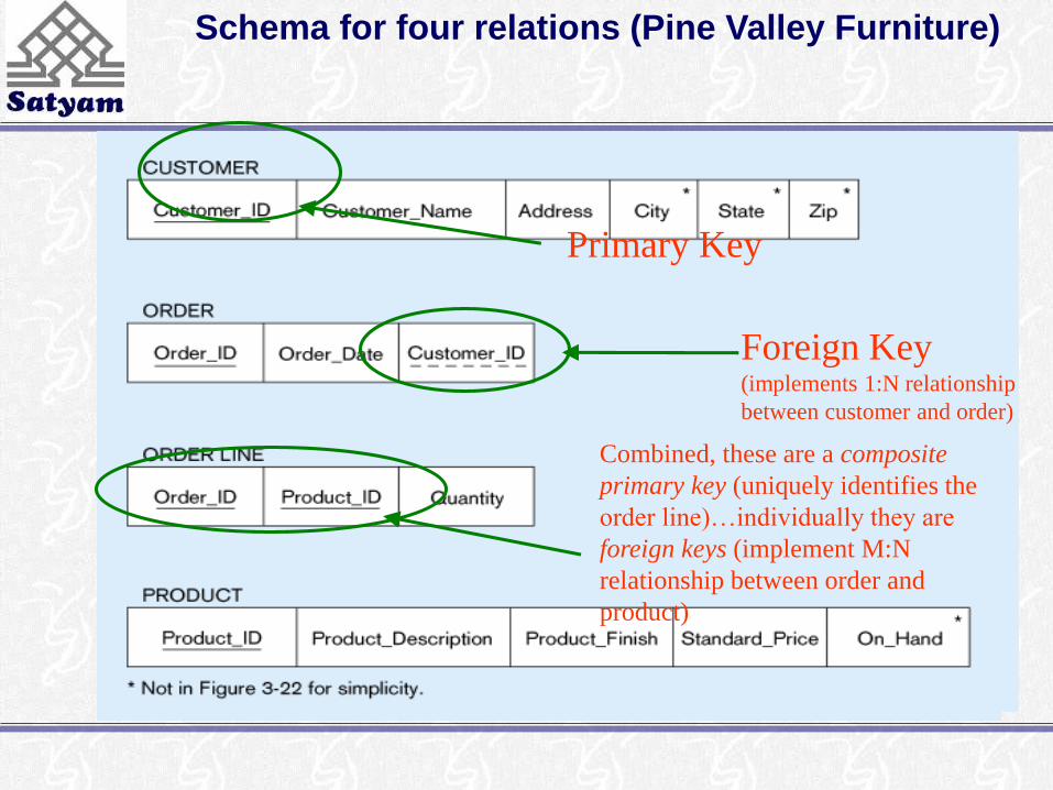
Schema for four relations (Pine Valley Furniture)
Primary Key
Foreign Key (implements 1:N relationship
between customer and order)
Combined, these are a composite
primary key (uniquely identifies the
order line)…individually they are
foreign keys (implement M:N
relationship between order and
product)

Integrity constraints
• These help maintain the accuracy and integrity of the data in the database
• Domain Constraints - a domain is the set of allowable values for an attribute.
• Domain definition usually consists of 4 components: domain name, meaning, data type, size (or length), allowable values/allowable range (if applicable)
• Entity Integrity ensures that every relation has a primary key, and that all the data values for that primary key are valid. No primary key attribute may be null.

Entity integrity
• In some cases a particular attribute cannot be assigned a data
value, e.g. when there is no applicable data value or the value
is not known when other values are assigned
• In these situations we can assign a null value to an attribute
(null signifies absence of a value)
• But still primary key values cannot be null – the entity
integrity rule states that “no primary key attribute (or
component of a primary key attribute) may be null
Integrity constraints
• A Referential Integrity constraint is a rule that maintains consistency among the rows of two relations – it states that any foreign key value (on the relation of the many side) MUST match a primary key value in the relation of the one side. (Or the foreign key can be null)
• In the following Fig., an arrow has been drawn from each foreign key to its associated primary key. A referential integrity constraint must be defined for each of these arrows in the schema

Referential integrity constraints (Pine Valley Furniture)
Referential
integrity
constraints are
drawn via arrows
from dependent to
parent table
Referential integrity
• How do you know if a foreign key is allowed to be null?
• In this example, as each ORDER must have a
CUSTOMER the foreign key of Customer_ID cannot be
null on the ORDER relation
• Whether a foreign key can be null must be specified as a
property of the foreign key attribute when the database is
designed
Referential integrity
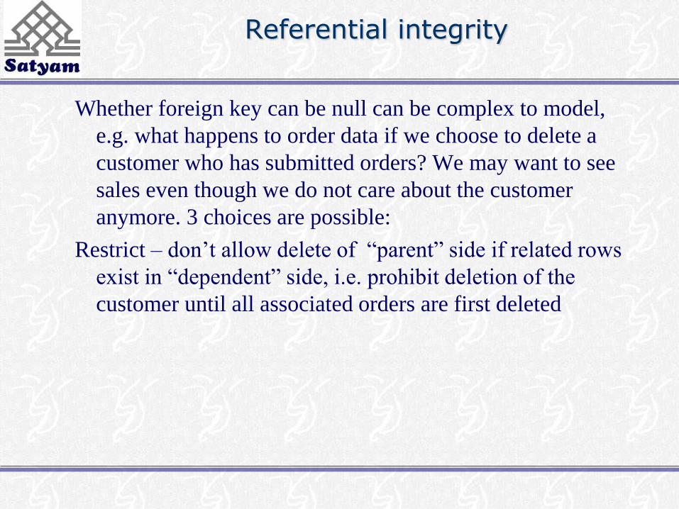
Whether foreign key can be null can be complex to model,
e.g. what happens to order data if we choose to delete a
customer who has submitted orders? We may want to see
sales even though we do not care about the customer
anymore. 3 choices are possible:
Restrict – don’t allow delete of “parent” side if related rows
exist in “dependent” side, i.e. prohibit deletion of the
customer until all associated orders are first deleted

Referential integrity
Cascade – automatically delete “dependent” side rows
that correspond with the “parent” side row to be
deleted, i.e. delete the associated orders, in which case
we lose not only the customer but also the sales history
Set-to-Null – set the foreign key in the dependent side to
null if deleting from the parent side - an exception that
says although an order must have a customer_ID value
when the order is created, Customer_ID can become
null later if the associated customer is deleted [not
allowed for weak entities]
Creating relational tables
• These example tables are created using CREATE TABLE
statements from SQL
• In practice, they are usually created in the implementation
phase later on in the development process
• However, we create them here to explain some concepts
• One table is created for each table shown in the relational
schema (previous Fig.)
Creating relational tables
• Each attribute is defined, taking the data type and length from
the domain definitions
• For example, the attribute Customer_Name can be defined as a
VARCHAR (variable character) type with length 25
• By specifying NOT NULL, each attribute can be constrained
from being assigned a null value
• The primary key for each table is specified using the
PRIMARY KEY clause at the end of each table definition

Creating relational tables
CREATE TABLE CUSTOMER
(CUSTOMER_ID VARCHAR(5) NOT NULL
CUSTOMER_NAME VARCHAR(25) NOT NULL
Etc.
PRIMARY KEY (CUSTOMER_ID);
Creating relational tables
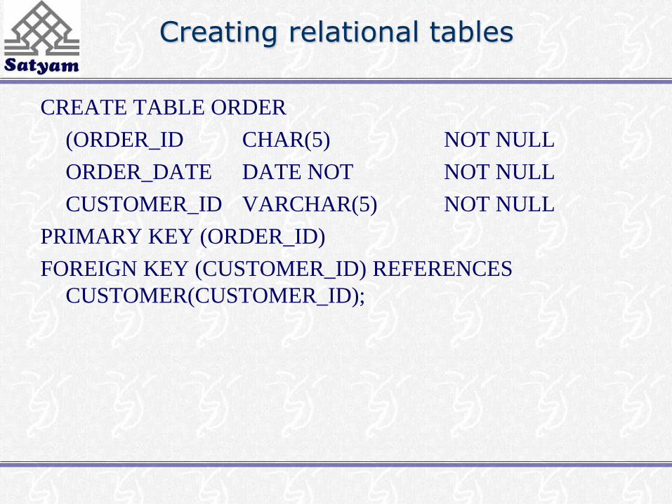
CREATE TABLE ORDER
(ORDER_ID CHAR(5) NOT NULL
ORDER_DATE DATE NOT NOT NULL
CUSTOMER_ID VARCHAR(5) NOT NULL
PRIMARY KEY (ORDER_ID)
FOREIGN KEY (CUSTOMER_ID) REFERENCES
CUSTOMER(CUSTOMER_ID);
Creating relational tables
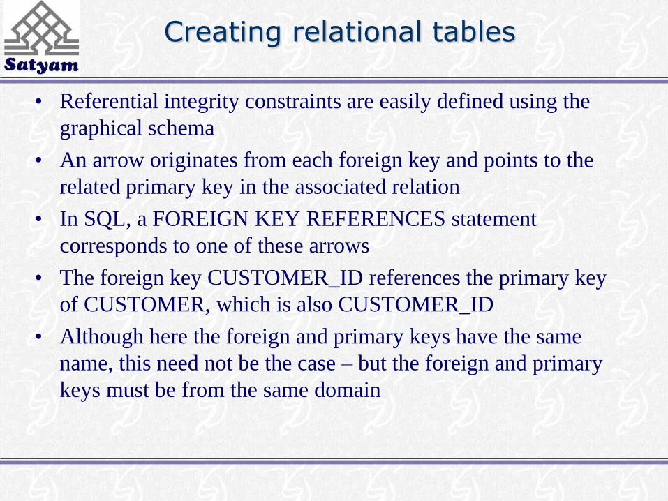
• Referential integrity constraints are easily defined using the
graphical schema
• An arrow originates from each foreign key and points to the
related primary key in the associated relation
• In SQL, a FOREIGN KEY REFERENCES statement
corresponds to one of these arrows
• The foreign key CUSTOMER_ID references the primary key
of CUSTOMER, which is also CUSTOMER_ID
• Although here the foreign and primary keys have the same
name, this need not be the case – but the foreign and primary
keys must be from the same domain
Creating relational tables
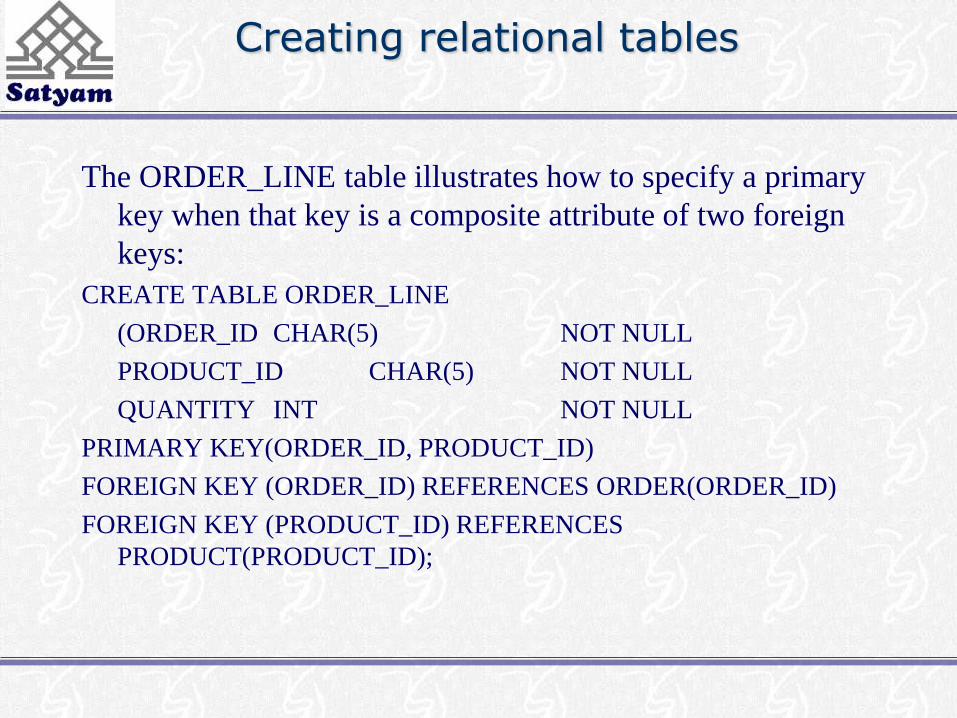
The ORDER_LINE table illustrates how to specify a primary
key when that key is a composite attribute of two foreign
keys:
CREATE TABLE ORDER_LINE
(ORDER_ID CHAR(5) NOT NULL
PRODUCT_ID CHAR(5) NOT NULL
QUANTITY INT NOT NULL
PRIMARY KEY(ORDER_ID, PRODUCT_ID)
FOREIGN KEY (ORDER_ID) REFERENCES ORDER(ORDER_ID)
FOREIGN KEY (PRODUCT_ID) REFERENCES
PRODUCT(PRODUCT_ID);
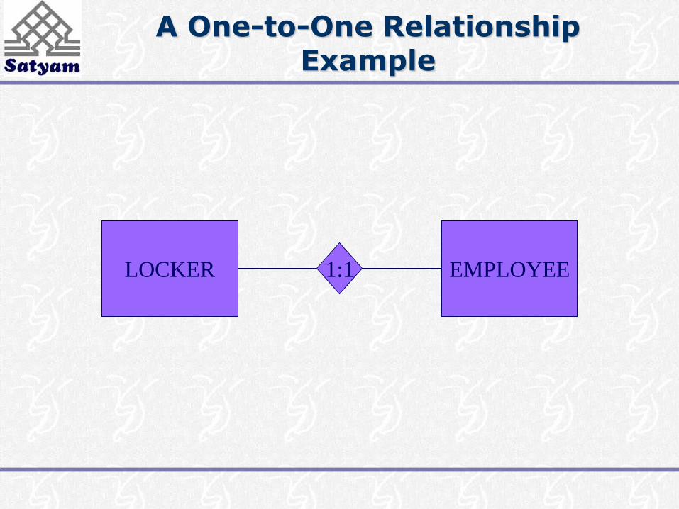
A One-to-One Relationship Example
LOCKER EMPLOYEE1:1
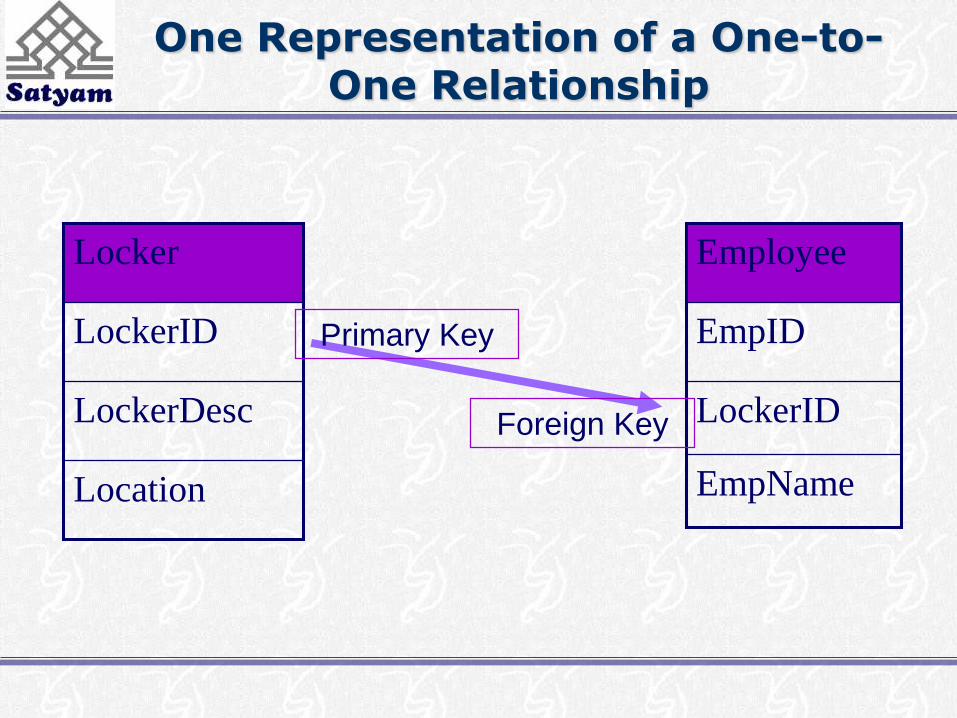
One Representation of a One-to-One Relationship
LockerDesc
Location
LockerID
Locker
LockerID
EmpName
EmpID
Employee
Foreign Key
Primary Key

Another Representation of a One-to-One Relationship
EmpID
LockerDesc
Location
LockerID
Locker
EmpName
EmpID
Employee
Foreign Key
Primary Key

Mandatory One-to-One Relationships
• A mandatory 1:1 relationship can easily be
collapsed back into one relation. While
there are times when the added complexity
is warranted…
– Added security
– Infrequently accessed data components
• …very often these relations are collapsed
into one

One-to-Many Relationships
• Like a 1:1 relationship, a 1:N relationship is
saved by placing the key from one table into
another as a foreign key. Where does the
foreign key go?
• In a 1:N the foreign key always goes into
the many-side
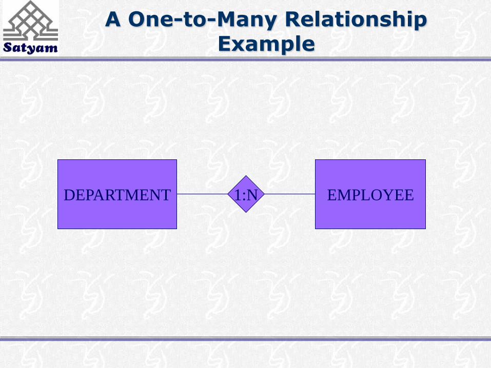
A One-to-Many Relationship Example
DEPARTMENT EMPLOYEE1:N
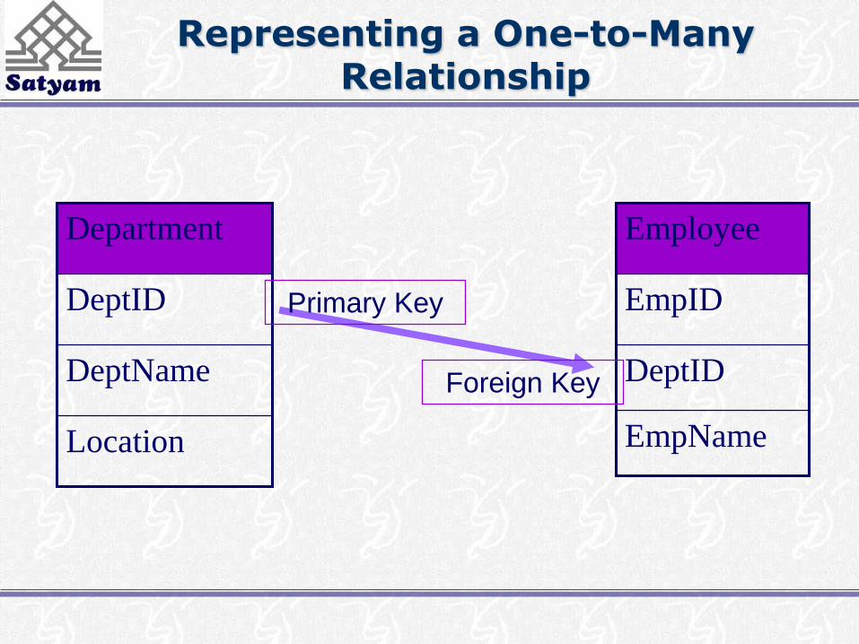
Representing a One-to-Many Relationship
DeptName
Location
DeptID
Department
DeptID
EmpName
EmpID
Employee
Foreign Key
Primary Key

Representing Many-to-Many Relationships
• To save a M:N relationship, a new relation is
created. This relation is called an
intersection relation. What is the primary
key of this new relation?
• An intersection relation has a composite key
consisting of the keys from each of the tables
that formed it

A Many-to-Many Relationship Example
SKILL EMPLOYEEN:M
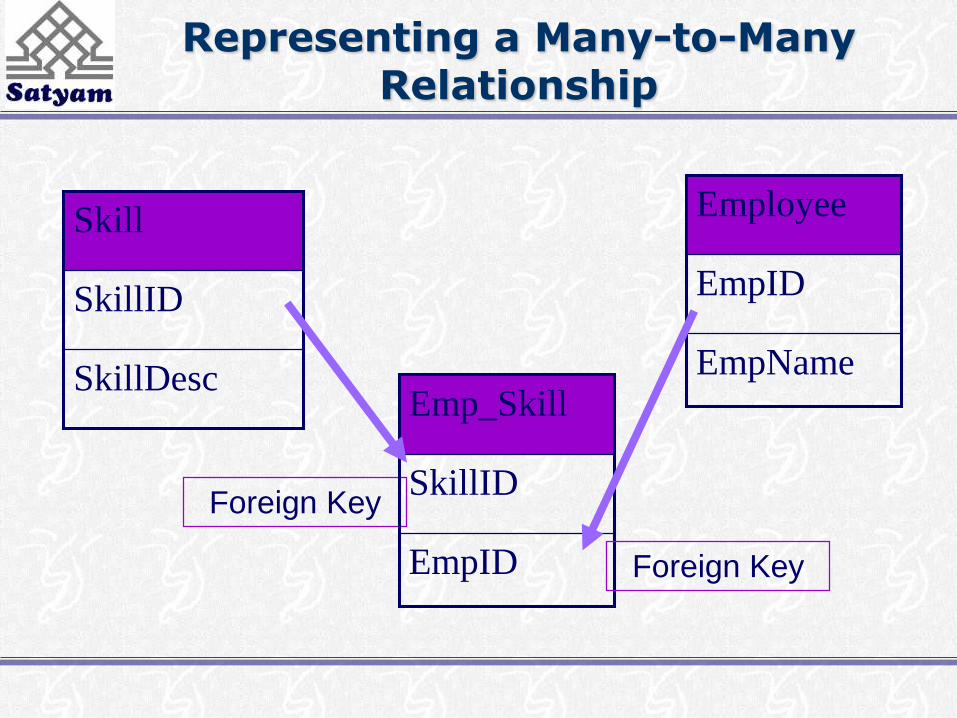
Representing a Many-to-Many Relationship
SkillDesc
SkillID
Skill
EmpName
EmpID
Employee
Foreign Key
EmpID
SkillID
Emp_Skill
Foreign Key
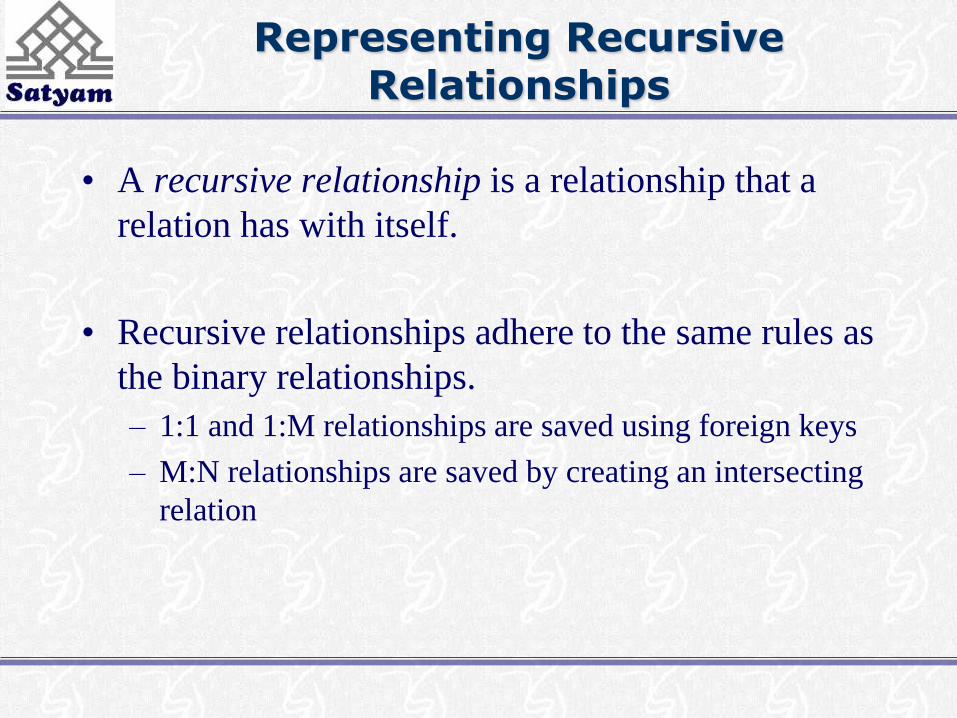
Representing Recursive Relationships
• A recursive relationship is a relationship that a
relation has with itself.
• Recursive relationships adhere to the same rules as
the binary relationships.
– 1:1 and 1:M relationships are saved using foreign keys
– M:N relationships are saved by creating an intersecting
relation

A Recursive Relationship Example
EMPLOYEE 1:N
Manages
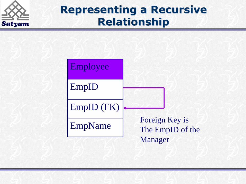
Representing a Recursive Relationship
EmpID (FK)
EmpName
EmpID
Employee
Foreign Key is
The EmpID of the
Manager

Well-structured relations
• A well-structured relation contains minimal redundancy and
allows users to insert, modify and delete the rows in a table
without errors and inconsistencies
• Redundancies in a table (such as more than one entry for each
EMPLOYEE) may result in errors and inconsistencies
(anomalies) when the table is updated
• 3 Types of anomaly are possible, insertion, deletion and
modification anomalies
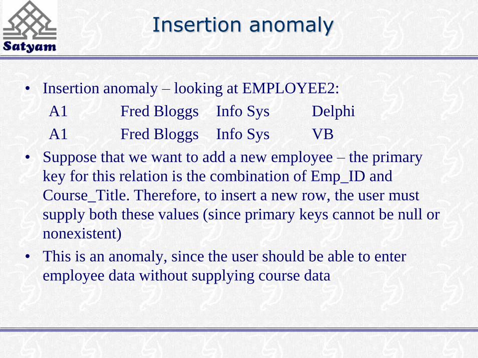
Insertion anomaly
• Insertion anomaly – looking at EMPLOYEE2:
A1 Fred Bloggs Info Sys Delphi
A1 Fred Bloggs Info Sys VB
• Suppose that we want to add a new employee – the primary
key for this relation is the combination of Emp_ID and
Course_Title. Therefore, to insert a new row, the user must
supply both these values (since primary keys cannot be null or
nonexistent)
• This is an anomaly, since the user should be able to enter
employee data without supplying course data

Deletion and Modification anomalies
• Suppose that the data for a particular employee are deleted
from the table
• This results in losing the information that this employee
completed a particular course
• This results in losing the information that this course was
offered – deletion anomaly
• If employee A1 changes the department they work in, this
must be recorded in both the rows of the table otherwise
the data will be inconsistent – modification anomaly
Anomalies
• These anomalies indicate that EMPLOYEE2 is not a well-
structured relation
• We should use normalisation theory (discussed later) to
divide EMPLOYEE2 into 2 relations, one called
EMPLOYEE1 and one called EMP_COURSE that keeps
track of the course details

Transforming ER diagrams into relations
• This can be done automatically by many CASE tools, but it
is important to understand because:
• Case tools often cannot model complex data relationships
such as ternary relationships and supertype/subtype
relationships. For these situations you may have to perform
these steps manually
• Sometimes alternative solutions exist, and you must
choose the best
• You must be able to quality check the CASE tool results

Remember entity types!
• Regular entities – have an independent existence and
generally represent real-world objects = [rectangles with a
single line]
• Weak entities cannot exist on there own, they exist with an
identifying relationship with an owner regular entity type =
[[rectangles with a double line]]
• Associative entities (gerunds) are formed from many-to-
many relationships between other entity types =
[<rectangle enclosing the diamond relationship symbol>]
Step 1: map regular entities
• Each regular entity type in an ER diagram is transformed into
a relation
• The name given to the relation is generally the same as the
entity type
• Each simple attribute of the type becomes an attribute of the
relation
• The identifier of the entity type becomes the primary key of
the corresponding relation
• The following 2 Figs. show an example of this

(a) CUSTOMER
entity type with
simple
attributes
Mapping a regular entity
(b) CUSTOMER relation
Composite attributes
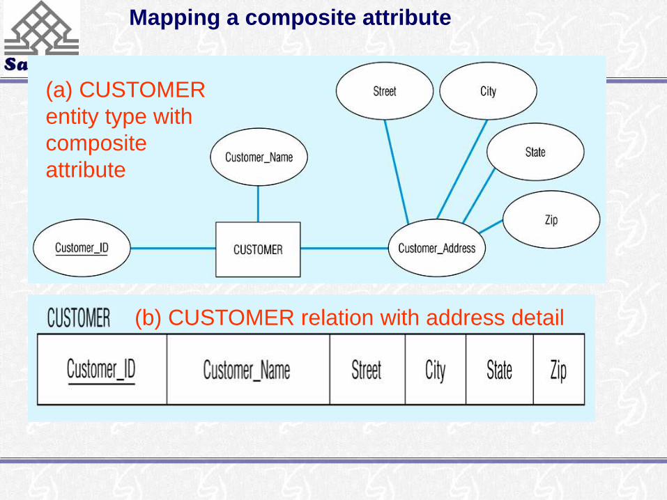
• When a regular entity type has composite attributes, only
the simple component attributes of the composite attribute
are included in the new relation
• The following Fig. Shows a variation on the previous one,
where Customer_Address is represented as a composite
attribute with components Street, City, State and Zip
(a) CUSTOMER
entity type with
composite
attribute
Mapping a composite attribute
(b) CUSTOMER relation with address detail

Multi-valued attributes
• Here two new relations (rather than one) are created
• First relation contains all of the attributes of the entity type
except the multivalued attribute
• Second relation contains two attributes that form the primary
key of the second relation
• The first of these is the primary key for the first relation, which
becomes a foreign key in the second relation
• The second is the multivalued attribute

Multi-valued attributes
• In the following Fig. EMPLOYEE has ‘Skill’ as a multi-
valued attribute
• The first relation EMPLOYEE has the primary key
Employee_ID
• The second relation EMPLOYEE_SKILL has the two
attributes Employee_ID and Skill, which form the primary key
• The relationship between foreign and primary keys is indicated
by the arrow in the figure
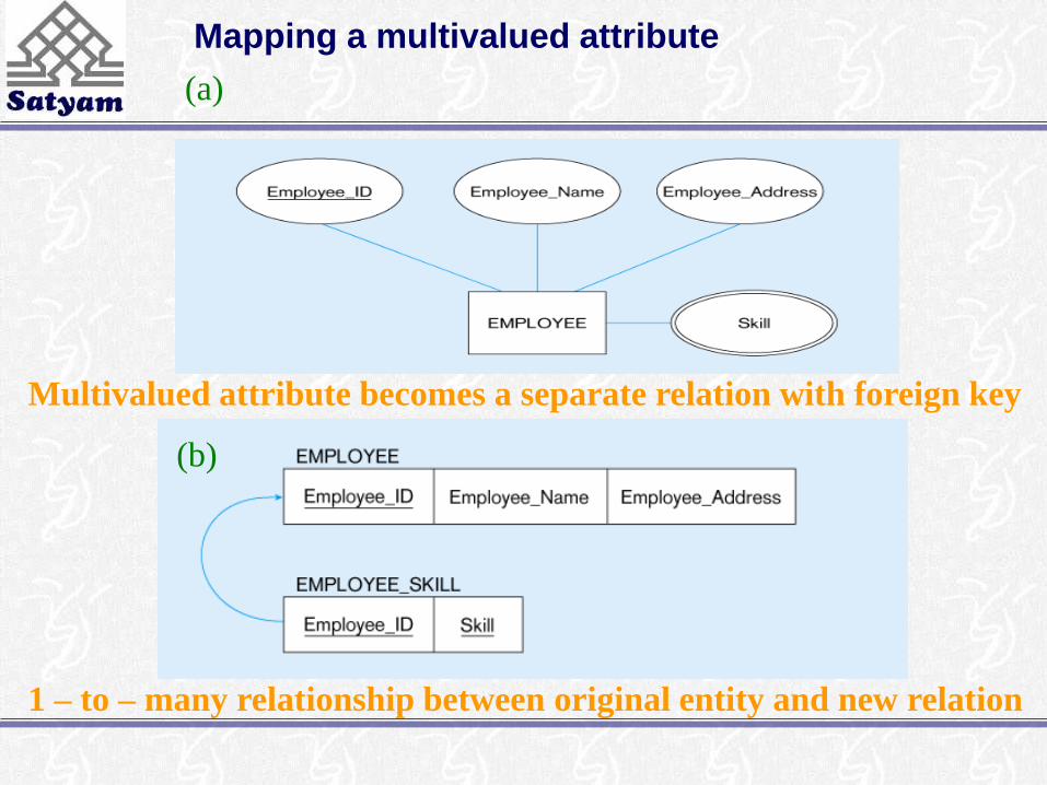
Mapping a multivalued attribute
1 – to – many relationship between original entity and new relation
(a)
Multivalued attribute becomes a separate relation with foreign key
(b)

Step 2: map weak entities
• You must already have created a relation corresponding to the
identifying type
• For each weak entity type, create a new relation and include all
of the simple attributes (or simple components of composite
attributes) as attributes of this relation
• Then include the primary key of the identifying relation as a
foreign key attribute in this new relation
• The primary key of the new relation is the combination of this
primary key of the identifying and the partial identifier of the
weak entity type
Map weak entities
• The following figure shows the weak identity type
DEPENDENT and its identifying entity type EMPLOYEE,
linked by the identifying relationship ‘Has’
• The attribute Dependent_Name (the partial identifier for this
relation) is a composite attribute with components First_Name,
Middle_Initial and Last_Name – so we assume that for a given
employee these items will uniquely identify a dependent. The
primary key of DEPENDENT consists of four attributes:
Employee_ID, First_Name, Middle_Initial and Last_Name.
The foreign key relationship with its primary key is indicated
by the arrow in the Fig.

Example of mapping a weak entity
(a) Weak entity DEPENDENT
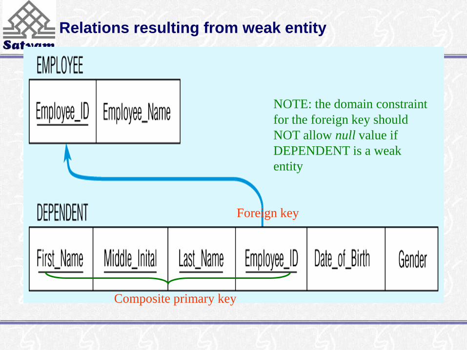
Relations resulting from weak entity
NOTE: the domain constraint
for the foreign key should
NOT allow null value if
DEPENDENT is a weak
entity
Foreign key
Composite primary key
Step 3: map binary relationships
• The procedure for representing relationships depends on
both the degree of the relationships (unary, binary, ternary)
and the cardinalities of the relationships
Map binary one-to-many (1:M)
• First create a relation for each of the two entity types
participating in the relationship
• Next include the primary key attribute(s) of the entity on
the one-side as a foreign key in the relation that is on the
many-side
• ‘Submits’ relationship in the following Fig. shows the
primary key Customer_ID of CUSTOMER (the one-side)
included as a foreign key in ORDER (the many-side)
(signified by the arrow)

Example of mapping a 1:M relationship
Relationship between customers and orders
Note the mandatory one
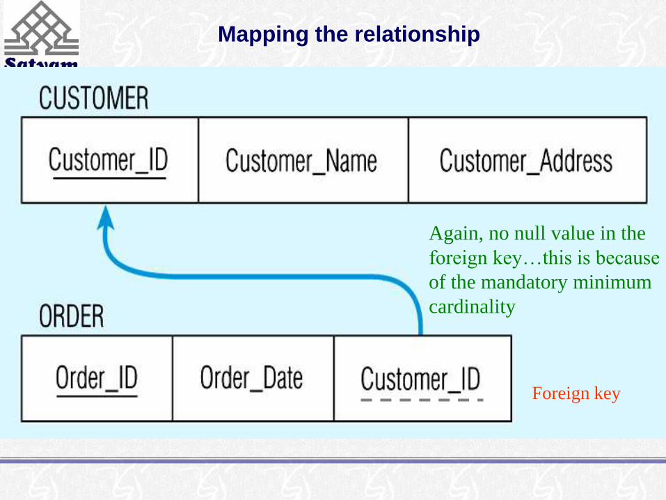
Mapping the relationship
Again, no null value in the
foreign key…this is because
of the mandatory minimum
cardinality
Foreign key

Map binary many-to-many (M:N) relationships
• If such a relationship exists between entity types A and B, we
create a new relation C, then include as foreign keys in C the
primary keys for A and B, then these attributes become the
primary key of C
• In the following Fig., first a relation is created for VENDOR
and RAW_MATERIALS, then a relation QUOTE is created
for the ‘Supplies’ relationship – with primary key formed from
a combination of Vendor_ID and Material_ID (primary keys
of VENDOR and RAW_MATERIALS). These are foreign
keys that point to the respective primary keys

Example of mapping an M:N relationship
The Supplies relationship will need to become a separate relation
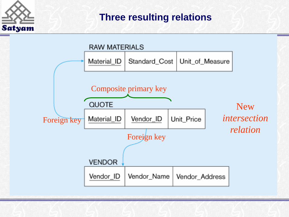
Three resulting relations
New
intersection
relationForeign key
Foreign key
Composite primary key
Map binary one-to-one relationships
• These can be viewed as a special case of one-to-many
relationships. Firstly, two relations are created, one for
each of the participating entity types
• Secondly, the primary key of one of the relations is
included as a foreign key in the other relation
• In a 1:1 relationship, the association in one direction is
nearly always optional one, whilst the association in the
other direction is mandatory one
• You should include in the relation on the optional side of
the relationship the foreign key of the entity type that has
the mandatory participation in the 1:1 relationship

Map binary one-to-one relationships
• This approach avoids the need to store null values in the
foreign key attribute
• Any attributes associated wit the relationship itself are also
included in the same relation as the foreign key
• The following Fig. Shows a binary 1:1 relationship
between NURSE and CARE_CENTER, where each care
centre must have a nurse who is in charge of that centre –
so the association from care centre to nurse is a mandatory
one, while the association from nurse to care centre is an
optional one (since any nurse may or may not be in charge
of a care centre)
Map binary one-to-one relationships
• The attribute Date_Assigned is attached to the In_Charge
relationship
• Since CARE_CENTER is the optional participant, the
foreign key (Nurse_In_Charge) is placed in this relation –
it has the same domain as Nurse_ID and the relationship
with the primary key is shown.
• The attribute Date_Assigned is also located in
CARE_CENTER and would not be allowed to be null

Mapping a binary 1:1 relationship
Binary 1:1 relationship

Resulting relations
Step 4: map associative entities
• When a user can best visualise a relationship as an associative
entity (rather than an M:N relationship) we follow similar
steps to mapping an M:N relationship
• Three relations are created, one for each of the two
participating entity types and the third for the associative entity
• The relation formed is called the associative relation
• The next step depends on whether on the ER diagram an
identifier was assigned to the associative entity
Identifier not assigned
• Here the default primary key for the associative relation
consists of the two primary key attributes from the other
two relations
• These attributes are then foreign keys that reference the
other two relations