1-Introduction to Software Engineering (Object Oriented Software Engineering - BNU Spring 2017)
Upload
hafiz-ammar-siddiquiCategory
view
186download
2
Object Oriented Analysis
FROM: HAFIZ AMMAR SIDDIQUI – COURSE: OBJECT ORIENTED SOFTWARE ENGINEERING – INSTITUTE: BEACONHOUSE NATIONAL UNIVERSITY
Static Models
FROM: HAFIZ AMMAR SIDDIQUI – COURSE: OBJECT ORIENTED SOFTWARE ENGINEERING – INSTITUTE: BEACONHOUSE NATIONAL UNIVERSITY
Static Models■ Represents the static elements of a system
■ Explains the structural organization of a system
■ Describes the static structure of objects that exist in the problem domain
■ Time independent view of system
■ Static modelling includes– Use case diagram– Class diagram– Object diagram– Component diagram– Deployment diagram
FROM: HAFIZ AMMAR SIDDIQUI – COURSE: OBJECT ORIENTED SOFTWARE ENGINEERING – INSTITUTE: BEACONHOUSE NATIONAL UNIVERSITY
Static Models (Object Model)
FROM: HAFIZ AMMAR SIDDIQUI – COURSE: OBJECT ORIENTED SOFTWARE ENGINEERING – INSTITUTE: BEACONHOUSE NATIONAL UNIVERSITY
Object Model■ System is modelled using object oriented techniques
■ Classified into different stages1. Analysis object model2. System design object model3. Object design model
FROM: HAFIZ AMMAR SIDDIQUI – COURSE: OBJECT ORIENTED SOFTWARE ENGINEERING – INSTITUTE: BEACONHOUSE NATIONAL UNIVERSITY
Static Models (Class Diagram)
FROM: HAFIZ AMMAR SIDDIQUI – COURSE: OBJECT ORIENTED SOFTWARE ENGINEERING – INSTITUTE: BEACONHOUSE NATIONAL UNIVERSITY
Class Diagram■ Class diagram is a static model diagram which is modelled using the UML (Unified
Modeling Language)
■ Show classes which are abstractions that specify the common structure, attributesand behaviors of a set of objects
■ Describes the structure of a system by using classes and objects, and therelationships among them
■ Used from data modeling of a specific domain to a detailed design of the system
FROM: HAFIZ AMMAR SIDDIQUI – COURSE: OBJECT ORIENTED SOFTWARE ENGINEERING – INSTITUTE: BEACONHOUSE NATIONAL UNIVERSITY
Object Modelling using UML
FROM: HAFIZ AMMAR SIDDIQUI – COURSE: OBJECT ORIENTED SOFTWARE ENGINEERING – INSTITUTE: BEACONHOUSE NATIONAL UNIVERSITY
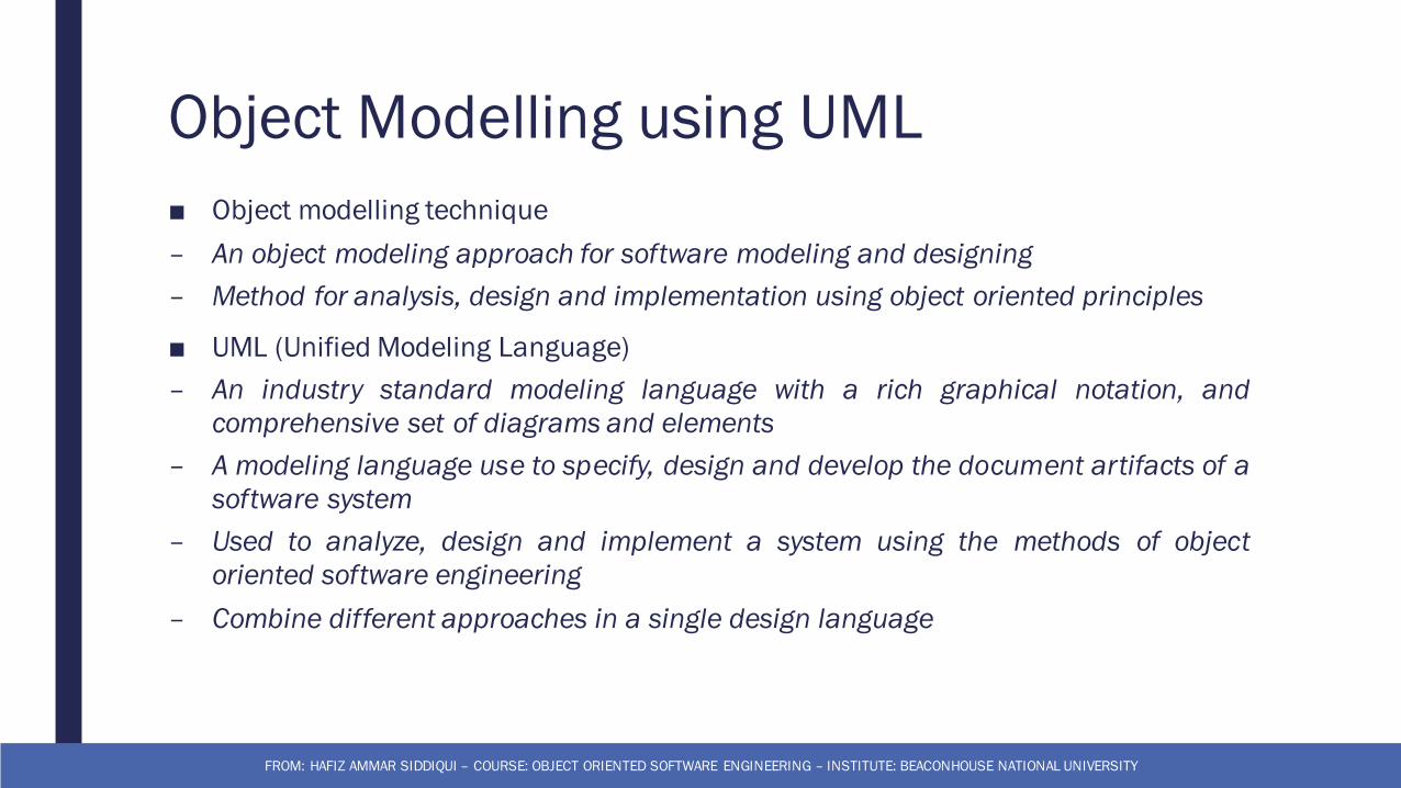
Object Modelling using UML■ Object modelling technique– An object modeling approach for software modeling and designing– Method for analysis, design and implementation using object oriented principles
■ UML (Unified Modeling Language)– An industry standard modeling language with a rich graphical notation, andcomprehensive set of diagrams and elements
– A modeling language use to specify, design and develop the document artifacts of asoftware system
– Used to analyze, design and implement a system using the methods of objectoriented software engineering
– Combine different approaches in a single design language
FROM: HAFIZ AMMAR SIDDIQUI – COURSE: OBJECT ORIENTED SOFTWARE ENGINEERING – INSTITUTE: BEACONHOUSE NATIONAL UNIVERSITY
The process of developing class diagram
FROM: HAFIZ AMMAR SIDDIQUI – COURSE: OBJECT ORIENTED SOFTWARE ENGINEERING – INSTITUTE: BEACONHOUSE NATIONAL UNIVERSITY
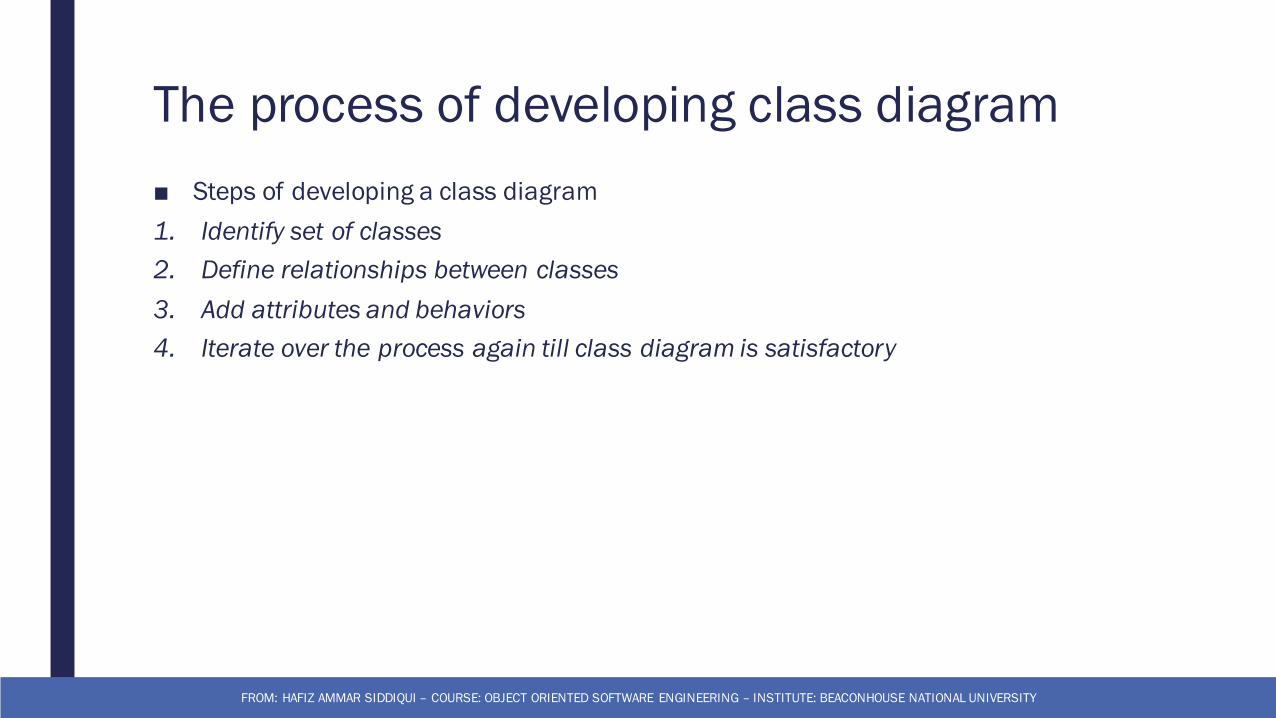
The process of developing class diagram■ Steps of developing a class diagram1. Identify set of classes2. Define relationships between classes3. Add attributes and behaviors4. Iterate over the process again till class diagram is satisfactory
FROM: HAFIZ AMMAR SIDDIQUI – COURSE: OBJECT ORIENTED SOFTWARE ENGINEERING – INSTITUTE: BEACONHOUSE NATIONAL UNIVERSITY
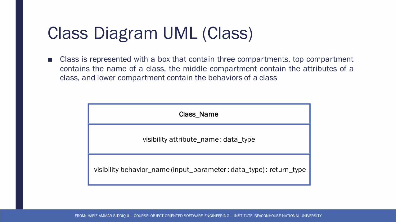
Class Diagram UML (Class)■ Class is represented with a box that contain three compartments, top compartment
contains the name of a class, the middle compartment contain the attributes of aclass, and lower compartment contain the behaviors of a class
FROM: HAFIZ AMMAR SIDDIQUI – COURSE: OBJECT ORIENTED SOFTWARE ENGINEERING – INSTITUTE: BEACONHOUSE NATIONAL UNIVERSITY
Class_Name
visibility attribute_name : data_type
visibility behavior_name (input_parameter : data_type) : return_type
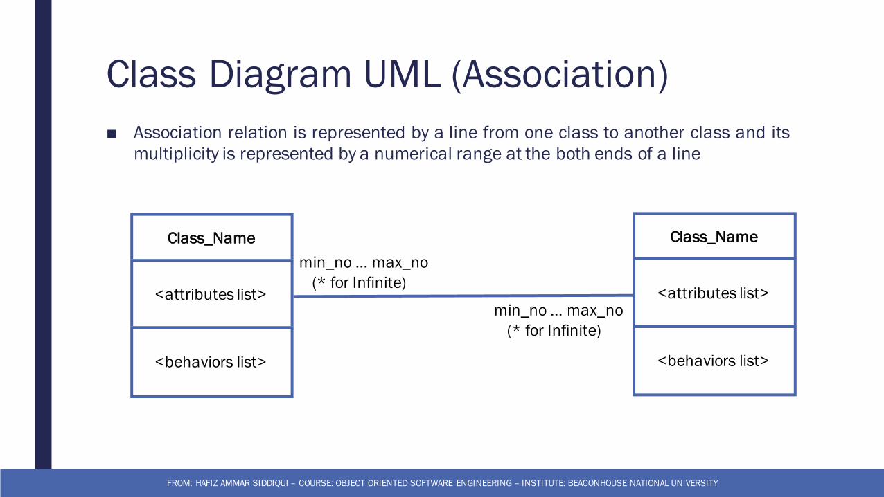
Class Diagram UML (Association)■ Association relation is represented by a line from one class to another class and its
multiplicity is represented by a numerical range at the both ends of a line
FROM: HAFIZ AMMAR SIDDIQUI – COURSE: OBJECT ORIENTED SOFTWARE ENGINEERING – INSTITUTE: BEACONHOUSE NATIONAL UNIVERSITY
Class_Name
<attributes list>
<behaviors list>
Class_Name
<attributes list>
<behaviors list>
min_no … max_no(* for Infinite)
min_no … max_no(* for Infinite)
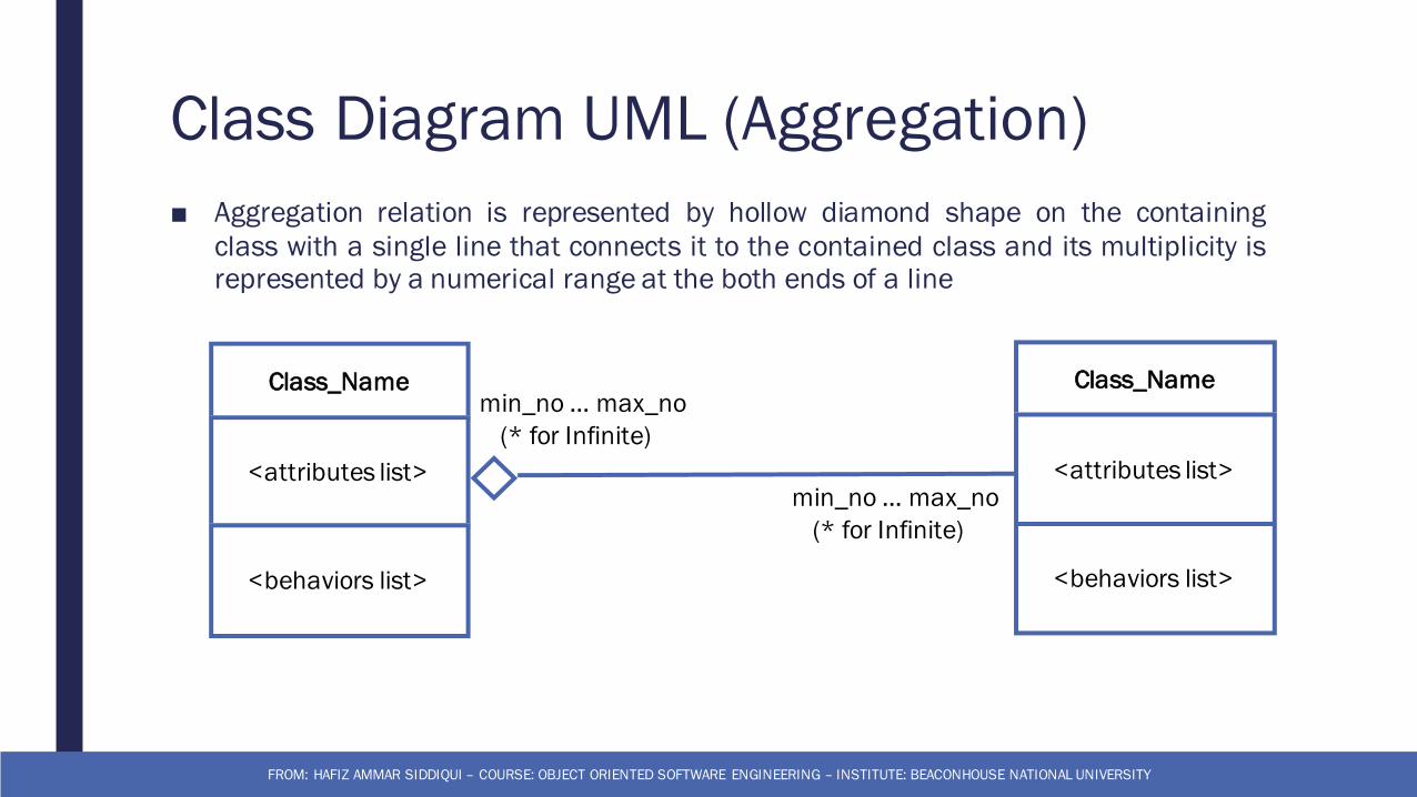
Class Diagram UML (Aggregation)■ Aggregation relation is represented by hollow diamond shape on the containing
class with a single line that connects it to the contained class and its multiplicity isrepresented by a numerical range at the both ends of a line
FROM: HAFIZ AMMAR SIDDIQUI – COURSE: OBJECT ORIENTED SOFTWARE ENGINEERING – INSTITUTE: BEACONHOUSE NATIONAL UNIVERSITY
Class_Name
<attributes list>
<behaviors list>
Class_Name
<attributes list>
<behaviors list>
min_no … max_no(* for Infinite)
min_no … max_no(* for Infinite)
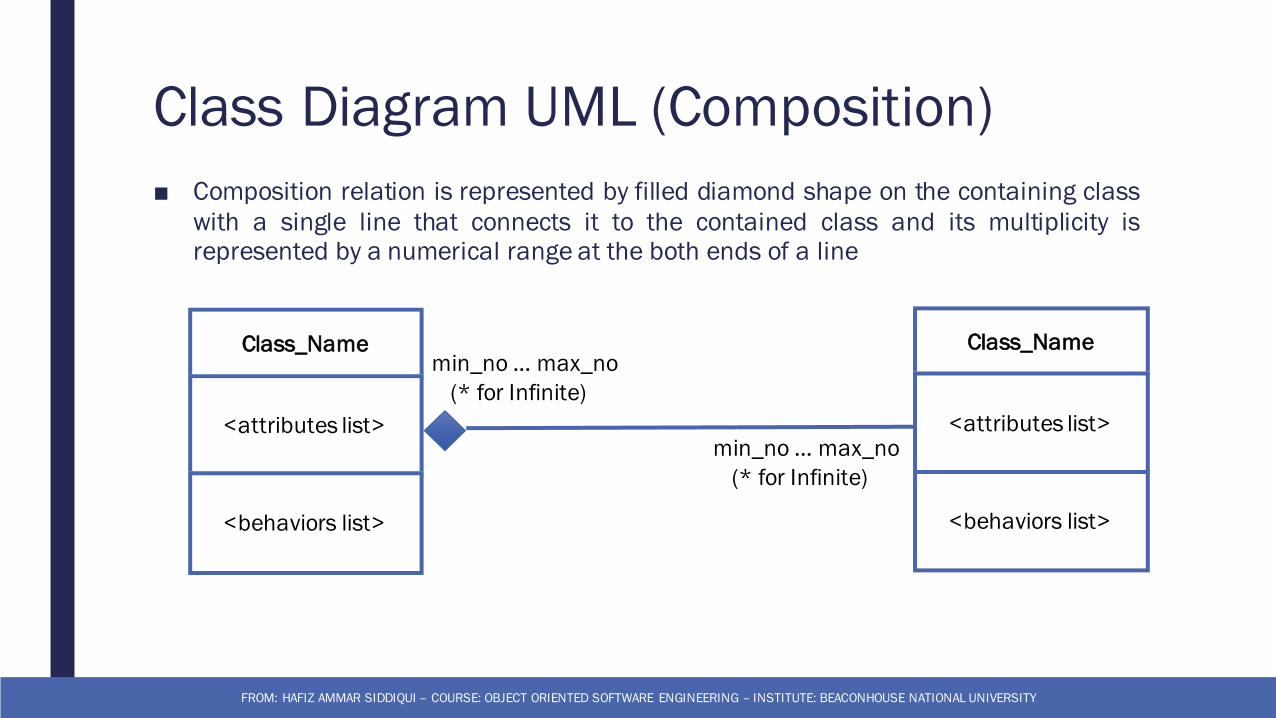
Class Diagram UML (Composition)■ Composition relation is represented by filled diamond shape on the containing class
with a single line that connects it to the contained class and its multiplicity isrepresented by a numerical range at the both ends of a line
FROM: HAFIZ AMMAR SIDDIQUI – COURSE: OBJECT ORIENTED SOFTWARE ENGINEERING – INSTITUTE: BEACONHOUSE NATIONAL UNIVERSITY
Class_Name
<attributes list>
<behaviors list>
Class_Name
<attributes list>
<behaviors list>
min_no … max_no(* for Infinite)
min_no … max_no(* for Infinite)
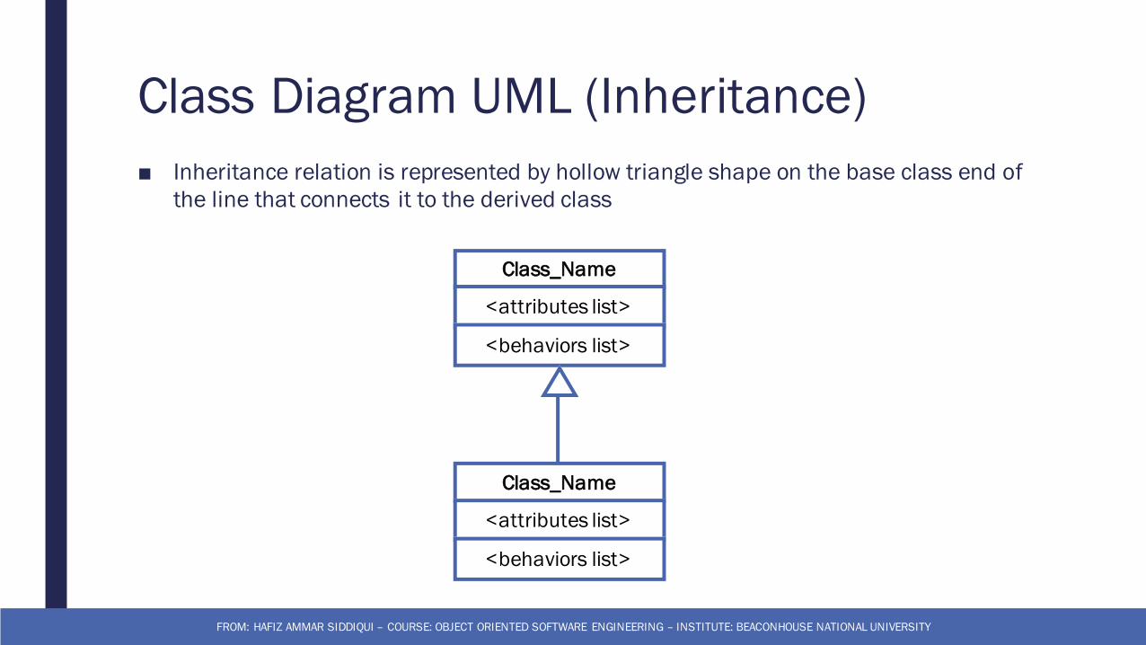
Class Diagram UML (Inheritance)■ Inheritance relation is represented by hollow triangle shape on the base class end of
the line that connects it to the derived class
FROM: HAFIZ AMMAR SIDDIQUI – COURSE: OBJECT ORIENTED SOFTWARE ENGINEERING – INSTITUTE: BEACONHOUSE NATIONAL UNIVERSITY
Class_Name
<attributes list>
<behaviors list>
Class_Name
<attributes list>
<behaviors list>
Dynamic Models
FROM: HAFIZ AMMAR SIDDIQUI – COURSE: OBJECT ORIENTED SOFTWARE ENGINEERING – INSTITUTE: BEACONHOUSE NATIONAL UNIVERSITY
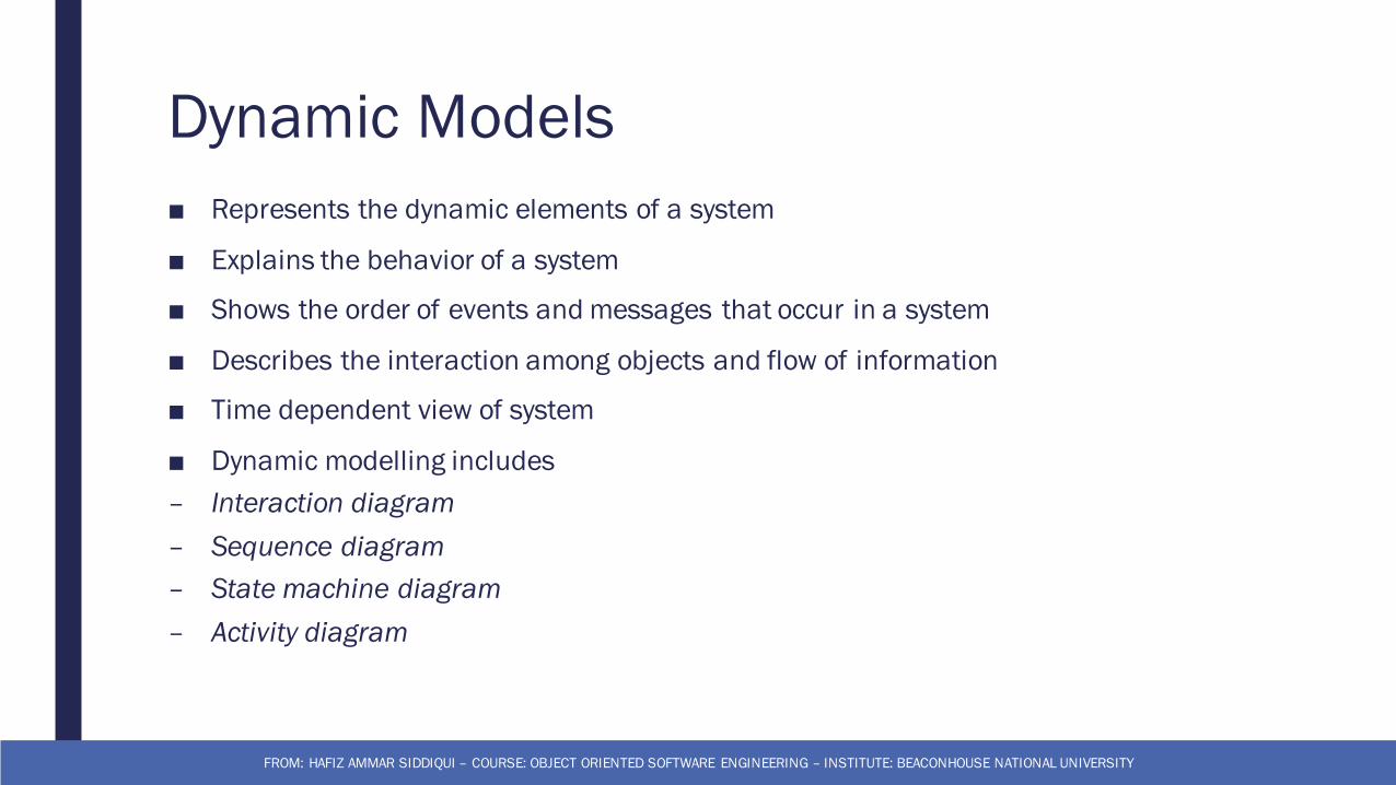
Dynamic Models■ Represents the dynamic elements of a system
■ Explains the behavior of a system
■ Shows the order of events and messages that occur in a system
■ Describes the interaction among objects and flow of information
■ Time dependent view of system
■ Dynamic modelling includes– Interaction diagram– Sequence diagram– State machine diagram– Activity diagram
FROM: HAFIZ AMMAR SIDDIQUI – COURSE: OBJECT ORIENTED SOFTWARE ENGINEERING – INSTITUTE: BEACONHOUSE NATIONAL UNIVERSITY
Dynamic Models (Sequence Diagram)
FROM: HAFIZ AMMAR SIDDIQUI – COURSE: OBJECT ORIENTED SOFTWARE ENGINEERING – INSTITUTE: BEACONHOUSE NATIONAL UNIVERSITY
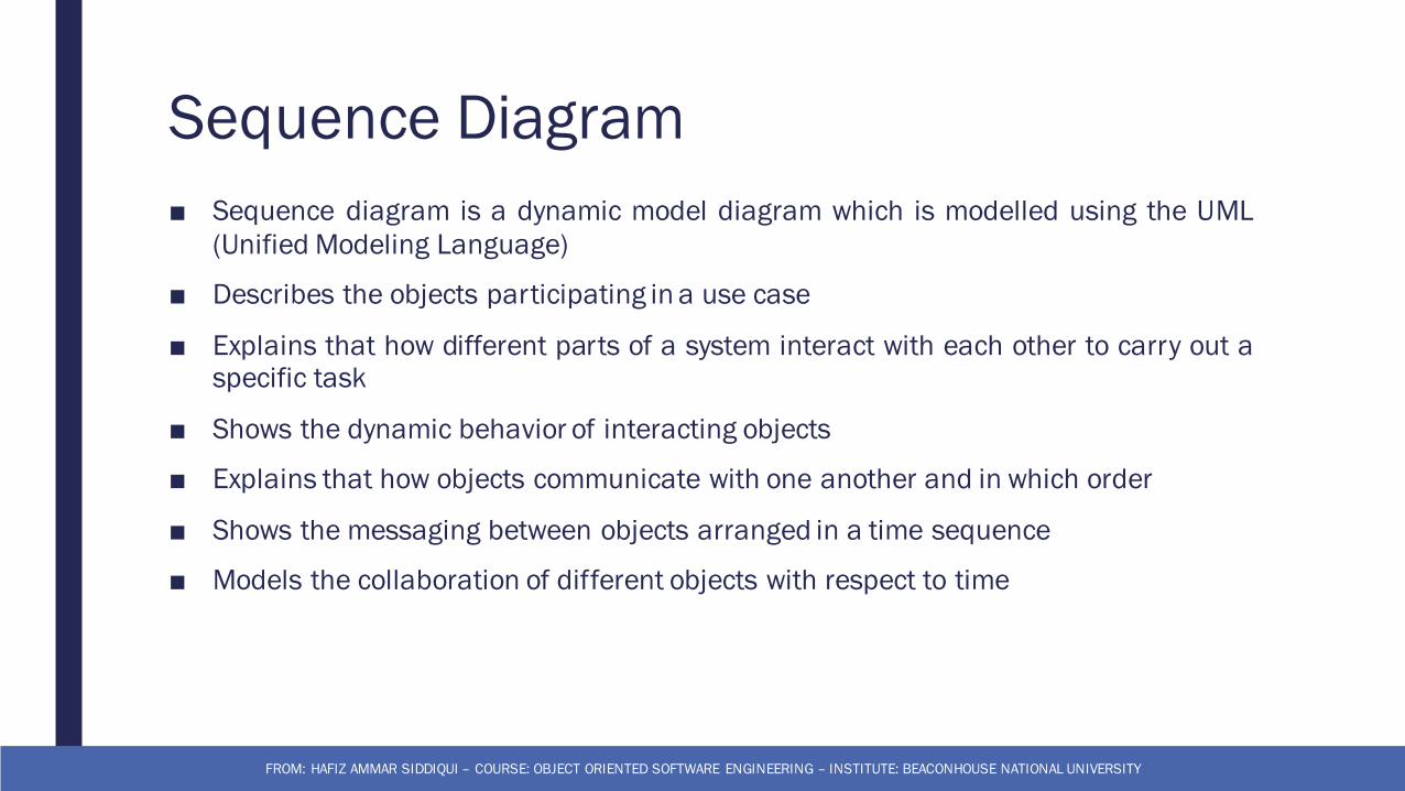
Sequence Diagram■ Sequence diagram is a dynamic model diagram which is modelled using the UML
(Unified Modeling Language)
■ Describes the objects participating in a use case
■ Explains that how different parts of a system interact with each other to carry out aspecific task
■ Shows the dynamic behavior of interacting objects
■ Explains that how objects communicate with one another and in which order
■ Shows the messaging between objects arranged in a time sequence
■ Models the collaboration of different objects with respect to time
FROM: HAFIZ AMMAR SIDDIQUI – COURSE: OBJECT ORIENTED SOFTWARE ENGINEERING – INSTITUTE: BEACONHOUSE NATIONAL UNIVERSITY
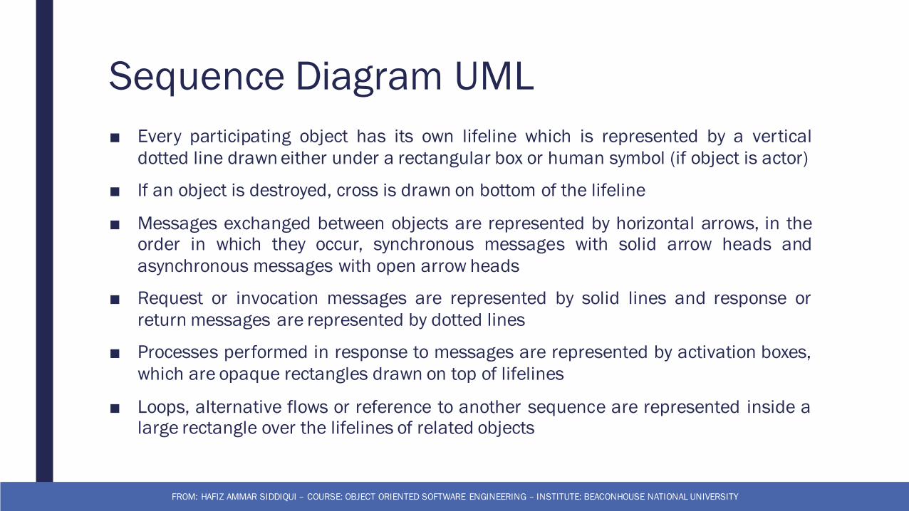
Sequence Diagram UML■ Every participating object has its own lifeline which is represented by a vertical
dotted line drawn either under a rectangular box or human symbol (if object is actor)
■ If an object is destroyed, cross is drawn on bottom of the lifeline
■ Messages exchanged between objects are represented by horizontal arrows, in theorder in which they occur, synchronous messages with solid arrow heads andasynchronous messages with open arrow heads
■ Request or invocation messages are represented by solid lines and response orreturn messages are represented by dotted lines
■ Processes performed in response to messages are represented by activation boxes,which are opaque rectangles drawn on top of lifelines
■ Loops, alternative flows or reference to another sequence are represented inside alarge rectangle over the lifelines of related objects
FROM: HAFIZ AMMAR SIDDIQUI – COURSE: OBJECT ORIENTED SOFTWARE ENGINEERING – INSTITUTE: BEACONHOUSE NATIONAL UNIVERSITY
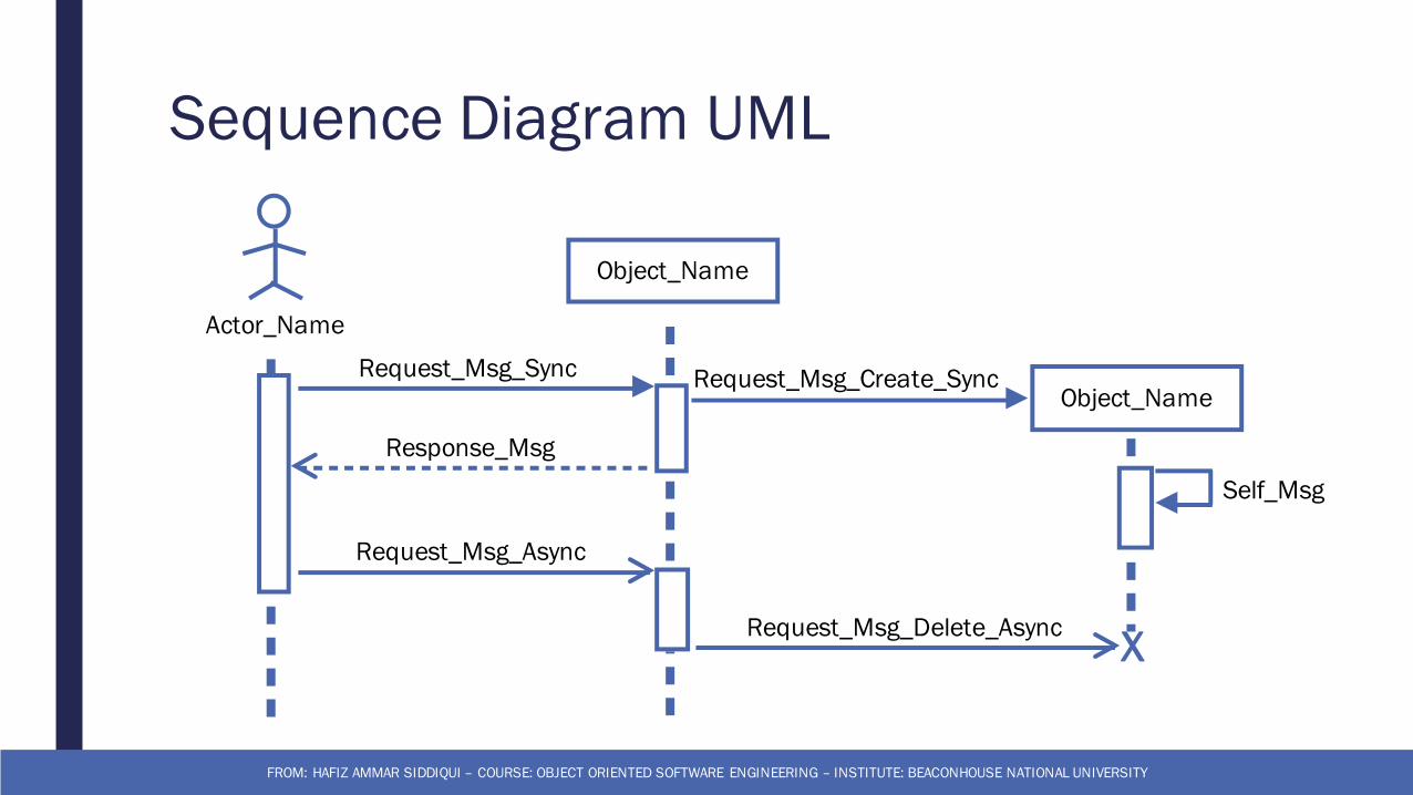
Sequence Diagram UML
FROM: HAFIZ AMMAR SIDDIQUI – COURSE: OBJECT ORIENTED SOFTWARE ENGINEERING – INSTITUTE: BEACONHOUSE NATIONAL UNIVERSITY
Object_Name
Actor_Name
Object_Name
X
Request_Msg_Sync Request_Msg_Create_Sync
Response_Msg
Request_Msg_Delete_Async
Request_Msg_Async
Self_Msg
Reference■ Object Oriented Software Engineering: Using UML, Patterns, and Java by Bernd
Bruegge, Allen H. Dutoit, Prentice Hall, 2010
FROM: HAFIZ AMMAR SIDDIQUI – COURSE: OBJECT ORIENTED SOFTWARE ENGINEERING – INSTITUTE: BEACONHOUSE NATIONAL UNIVERSITY