
5 IMcDonnell-Douglas Astronautics 4ENTRY PROBE IMcDonnell-Douglas Astronautics. 4. Ca.,) 60 p HC...
57
NASA CONTRACTOR NASACR-137875 R E P O R T NAV1976 (NASK-CR-13787 5 ) SPACECEAFT RECEIVING Mo ANTENNA STUDY: OUTER PLANETS ATMOSPHERIC N77-3135 4 ENTRY PROBE IMcDonnell-Douglas Astronautics Ca.,) 60 p HC A04/MF A-01 CSCL 09C Unclas --- G3/32 47022, SPACECRAFT RECEIVING ANTENNA STUDY Outer Planets Atmospheric Entry Probe SEP10977 - By E.A. Kuhiman 7 S1EP1 tr3 Preparedby MCDONNELL DOUGLAS ASTRONAUTICS COMPANY - EAST St. Louis, Missouri 63166 (314) 232-0232 fr A.: ; :s Research Center MoffrtFiel. California 94035 IVJAIISAL AER10PJALICS AMD SPACE ADMINISTRATIIJIM
Transcript of 5 IMcDonnell-Douglas Astronautics 4ENTRY PROBE IMcDonnell-Douglas Astronautics. 4. Ca.,) 60 p HC...

NASA CONTRACTOR NASACR-137875
R E P O R T NAV1976
(NASK-CR-137875 ) SPACECEAFT RECEIVINGMo ANTENNA STUDY: OUTER PLANETS ATMOSPHERIC N77-31354ENTRY PROBE IMcDonnell-Douglas Astronautics
Ca.,) 60 p HC A04/MF A-01 CSCL 09C Unclas
--- G3/32 47022,
SPACECRAFT RECEIVING ANTENNA STUDY
Outer Planets Atmospheric Entry Probe
SEP10977 -
By E.A. Kuhiman 7S1EP1 tr3
Preparedby
MCDONNELL DOUGLAS ASTRONAUTICS COMPANY - EAST
St. Louis, Missouri 63166 (314) 232-0232
fr A.: ; :s Research Center
MoffrtFiel. California 94035
IVJAIISAL AER10PJALICS AMD SPACE ADMINISTRATIIJIM
https://ntrs.nasa.gov/search.jsp?R=19770024410 2020-03-27T15:42:34+00:00Z
NASA CR-137875
SPACECRAFT RECEIVINGANTENNA STUDY
Outer Planet Atmospheric Entry Probe
By E.A. Kuhlman
Distribution of this report is provided in the interest of information exchange. Responsibility for the contents
resides in the author or organization that prepared it.
Prepared Under Contract No. 2-9027 by
MCDONNELL DOUGLAS ASTRONAUTICS COMPANY - EAST
Saint Louis, Missouri
for
AMES RESEARCH CENTER
NATIONAL AERONAUTICS AND SPACE ADMINISTRATION
TABLE OF CONTENTS
TABLE OF CONTENTS ........ iii
LIST OF FIGURES .................... ............ v
LIST OF tABLES .... ........... ....................... vii
SUMMARY .............................. .... . 1
INTRODUCTION ."................................ 3
ANTENNA DESIGN...... . .......... ..... .... 5Candidate Antenna-Designs. ..... 5
Lindenblad antenna.................. . . .. 6Conical spiral antenna ................. .... 6Loop-vee antenna . ...................... . 7Quadrifilar helix antenna ........ ..............7
Antenna Selection .................... ........ 7
MODEL ANTENNA TESTS ................ .......... .. 13Test Antenna............................ 13Test Setup .......... ................. 14Test Configurations ........... 15
. 1.......,.. . . . 5Configuration No. Configuration No. 2. ..................... 15Configuration No. 3....................... 15
- Configuration No. 4............... ...... 15Test-Results .. . . .. ............. ........ ..15
Radiation patterns ................. ....... 15Impedance ............. ................ 16Bandwidth ................. ............16
CONCLUSIONS...................................... .... 53
REFERENCES............... ... . ........ ...55
ACKNOWLEDGEMENTS .................. ............... 57
piiU AGNOTAi

LIST OF FIGURES
FIGURE
9I Lindenblad Antenna ...................... Single2 Calculated Radiation Patterns of Lindenbiad Antenna -
9Element and Two Element Array ............... .
Typical Conical Spiral Antenna .......... . . . 10 103
4 Loop-Vee Antenna ........ ...................... 5 Quadrifilar Helix Antenna - 3/4 Wavelength, 3/4 Turn ....... 11
6 Typical Radiation Pattern for a 3/4 Wavelength, 3/4 Turn... ................... 12Quadrifilar Helix .....
........ . ..... 177 Model Quadrifilar Helix Antenna .... 8 Radiation Patterns with Quadrifilar Helix Elements Wrapped
2.17Around Balun Feed -9
.................
11 Pioneer Spacecraft Test Configuration ... ........ .
Coordinate System for Antenna Pattern Measurements ....... 2412 13 Model Spacecraft Support Fixture-for Radiation Pattern
............Measurements ........ .. .. 14
............Configuration .... ............. .16 Antenna Position Rotated 22.50 Relative to Basic Test
.......
17 .
21 Radiation Patterns for Test Configuration No. 4 -2.2 GHz .20
Radiation Patterns for Test Configuration No. 2 2.2 GHz ..40Radiation Patterns for Test Configuration No. 3 2.2 GHz ..45
18 Radiation Patterns for Test Configuration No. 1 2.2 GHz
19
22 Radiation Patterns for Bandwidth Evaluation -2.0 GHz .23 Radiation Patterns for Bandwidth Evaluation -2.3 GHz . . .5224
LIST OF PAGES
Title Page
ii thru viiii thru 57
GHz ................ ..... Radiation Patterns of 3/4x-3/4 Turn Quadrifilar
Helix18
.. 20Antenna - 2.2 GHz ..... ... 10 VSWR of 3/4x-3/4 Turn Quadrifilar Helix Antenna .. ....... 23
.23
...
.
25 Basic Spacecraft Test Configuration .... .............
15 Antenna Extended Axially Aft of Position for Basic Test26
27
28Configuration . . . ........... Antenna Extended Axially Aft for Rotated Position-.. . ..29
.30
.35
VSWR of Antenna Mounted on Spacecraft .... ........ ..50.51
VEG PAGE BLANK Nfl V

LIST OF TABLES
8
II Maximum Pattern Dissymmetry (dB) ............. . ...... 16
III Maximum Axial Ratio (dB) .. ..... ................ 16
I Antenna Characteristics ...................
* 0 PAG BLANK NOT PILM3
vii
SUMMARY
As a result of trade-off and selection studies, a quadrifilar helixantenna was selected for the Pioneer spacecraft receiving antenna. A model wasconstructed for radiation pattern measurement at 2.2 GHz (550 MHz full scale).
°The pattern symmetry is within 1 dB from the zenith (a= 0 ) to 100 above the= ° equatorial plane (a 800). Above e = 90 the pattern symmetry and axial ratio
degrade slowly. Over this same region the axial ratio varies from 0 to 1.5 dB.It is believed that further improvement could only be obtained with precisiontooling.
Radiation patterns were measured with the model quadrifilar helix antennamounted on a Pioneer spacecraft model. Four different configurations weretested. The results show that the antenna-location does not have a major
=effect on its patterns over the aft hemisphere (6 = 00 to a 90°). However,moving the antenna away from the spacecraft improves the antenna performance from e = 900 to a = 110'. Measurements were also made to evaluate the effectof the spacecraft on the VSWR and bandwidth of the antenna and found to be veryminor. The peak circular gain of the quadrifilar helix antenna should beabout 2.2 dB based on an expected efficiency of 71% (-1.5 dB) for a full scaleantenna.
Radiation patterns and VSWR plots are given to demonstrate the performanceof the antenna in the various test configurations.
I

INTRODUCTION
The radiation patterns of the spacecraft receiving antenna are animportant item in the design df the Outer Planets Probe (OPP) communicationslink; Since the Pioneer spacecraft-spins about its roll axis, an axiallysymmetric receiving antenna jiaiterf is required for best link stability. Formaximum link power.transfer, circular polarization (with same sense as probetrans'mitting)and pr6per.radiation pattern distribution are required. Thelatter is a function of the:spaecraWand probe trajectories. If the range of look angles (relative to spacecraft)" is small and near the equatorial planeof the spacecraft, two elements can.be~arrayed to increase the gain in thedesired region. This'would.also have an added benefit by increasing'the noiserejection in the null region.- However, if the range of look angles is large asingle radiation element~is probably required. In this case, the control ofthe radiation pattern distribution is limited.
The objective of this task (Task 4.1.2) is to select and test an antenna
which has an axially symmetric radiation pattern with the pattern beam orientec
to cover a spacecraft look angle region defined by a Jupiter mission.
The study approach consisted of selecting an antenna design from a number
of candidate designs, constructing a 1/4-scale model of the antenna, and thenmeasuring radiation patterns with the antehna appropriately mounted on a 1/4
scale Pioneer spacecraft model at several feasible locations. The Pioneer.model was provided by NASA-ARC and was updated to include equipment requiredfor a Jupiter mission prior to delivery to MDAC-E.-
This report describes the selected antenna design, the configurationstested, and gives the test data necessary to evaluate effects of the spacecraft on the antenna radiation pattern and the performance of that-antennarelative to OPP missions.
Mmwe!N MM DBLAK Nff Puma
ANTENNA DESIGN
This section describes the dandidate antenna designs and discusses theselection of a receiving antenna design for a spn.spacecraft during the postentry communications period.
Candidate Antenna Designs
The primary radiation pattern requirements selected for the spacecraftreceiving-antenna (Table 19, Reference 1) are as follows:
a. Roll Planeso Pattern Symmetry - 1 dB peak to peak (goal)
b. Elevation Planes°o Beamwidth - 79.2
o Beam Center - 39.60o Spacecraft View Angles - 0 = 32.5 to 96..50
(Note: 0 = 00 at zenith)
c. Polarizationo Circular
Other antenna factors of importance are gain and efficiency. However, theseare largely dependent upon.the antenna type selected. The frequency used.forthis study was 550 MHz.
Antenna types which are circularly polarized and have essentially axially symmetric patterns include the following:
a. Lindenblad
b. conical spiral
c. loop-vee
d. quadrifilar helix
A brief review of other antenna types did not identify a potential candidate which had performance characteristics'preferable to those cited above.Therefore, those listed above were the only candidate designs given seriousconsideration. The primary items of consideration in the-antenna selectiontrade study were the antenna radiation pattern characteristics, patternisolation from spacecraft structure and size. Other items of consideration such as pattern control feasibility, implementation feasibility, compatibilitywith spacecraft systems, weight and complexity were given only minor consideration except where they were obviously important as factors i6 the choicebetween two otherwise equal 'candidates.

Lindenblad antenna. - The single element Lindenblad antenna (Figure 1) hasa circularily polarized radiation pattern with a beamwidth of about 80G whichis normal to the antenna axis. The pattern in any elevation plane can beapproximated by:
=E(e) sin I '3 6
where a = 00 is coincident with the antenna axis. The pattern is axiallysymmetric in any azimuth conic plane. The peak directivity for this patternis 2.10 dB. For a uniform (omnidirectional) opposite sense polarization levelof -20 dB, the directivity would be reduced about 0.07 dB. At the initial
=spacecraft view angle (a 32.50), the directivity of a Lindenblad antennawould be -5.91 dB, about 9.7 dB below that required (Reference 1). Lindenbladelements can be .arrayed and phased to point the beam off broadside. This wouldbe expected to narrow the beam and increase the gain. However, as the beam isscanned off the normal, a sidelobe starts to emerge which reduces the
=directivity of the main beam. The gain at e 32.50 (spacecraft look angle)for fixed beam angles 30 and 41.80 off broadside (6 phase = 90' and 1200respectively) is essentially the same as that for the single Lindenblad element.Figure 2 shows calculated elevation patterns for a single element and twoelements arrayed with the phase differences cited above: More elements couldbe added to suppress the side lobes, but this would result in an even narrowerbeamwidth and would likely require active beam direction control.
The volume required for a single Lindenblad element at 550 MHz is essentially a cylinder 33.5 cm (13.2 in.) in diameter and 19.3 cm (7.6 in.) inlength. The weight would not be a significant factor, but the complexity andcantilevered elements could be-expected to result in numerous implementationproblems associated with shock and vibration requirements.
Therefore, since the Lindenblad antenna radiation pattern gain iswellbelow (approximately 9.7 dB) that of the ideal antenna radiation patterncharacteristics (Reference 1) and as its mechanical design is not ideal, itwas rejected as a viable candidate for the spacecraft receiving antenna.
Conical spiral antenna. - A review of the radiation pattern characteristics of the conical spiral antenna (Figure 3) indicates that the patternsymmetry is on the order of 3 dB peak to peak. The dissymmetry is due, inpart, to the broad band characteristics of the conical'spiral. It is possible,'however, that additional development could improve the pattern symmetry. Theradiation pattern shape is similar to a loop-vee. In an elevation plane the
°beamwidth is about 55 centered'approximately a = 60'. The peak circularly polarized gain is about 3 dB. The angle at which the pattern peak occurs andthe beatmidth can be altered to some extent by altering the cone angle andthe pitch angle of the element windings. However, the pattern symmetryis expected to vary as the spiral arm geometry changes.
The volume required (estimated) is essentially a cone with a base diameter
,6

Loop-vee antenna. - The loop-vee antenna (Figure 4) has previously beenselected as the spacecraft receiving antenna (Reference 2). Details of theloop-vee antenna and its pattern characteristics are given in Reference 2 andwill not be repeated here. This data indicates that the azimuthal patternvariation is about 1 dB peak to peak. Data received from Vega PrecisionLaboratories Incorporated pertaining to their Model 837S loop-vee antenna indicates that peak to peak azimuthal variations of 2 to 2 1/2 dB can beexpected. Other private discussions of the loop-vee antenna capabilitiesindicated that the radiation pattern of the loop-vee antenna is stronglyinfluenced by the physical environment. This appears to be due to the requiredbalance between the horizontally polarized component of the loop and thevertically polarized component of the vertical "vee" elements. The addition ofdielectric members -(Reference 2) required to stabilize the four vertical andloop segment members may affect the symmetry of the pattern.
A comparison of the loop-vee radiation pattern (Reference 2) with anidealized Gaussian pattern (Table 32 of Reference 1) shows that the loop-veehas a negative margin of -3.29 dB at o = 32.50 and positive margin of 3.05 dBat e= 96.5'.
The volume required for the loop-vee antenna at 550 MHz is essentially acylinder 22.9 cm (9.0 in.) in diameter and 19.1 cm (7.5 in.) in length.
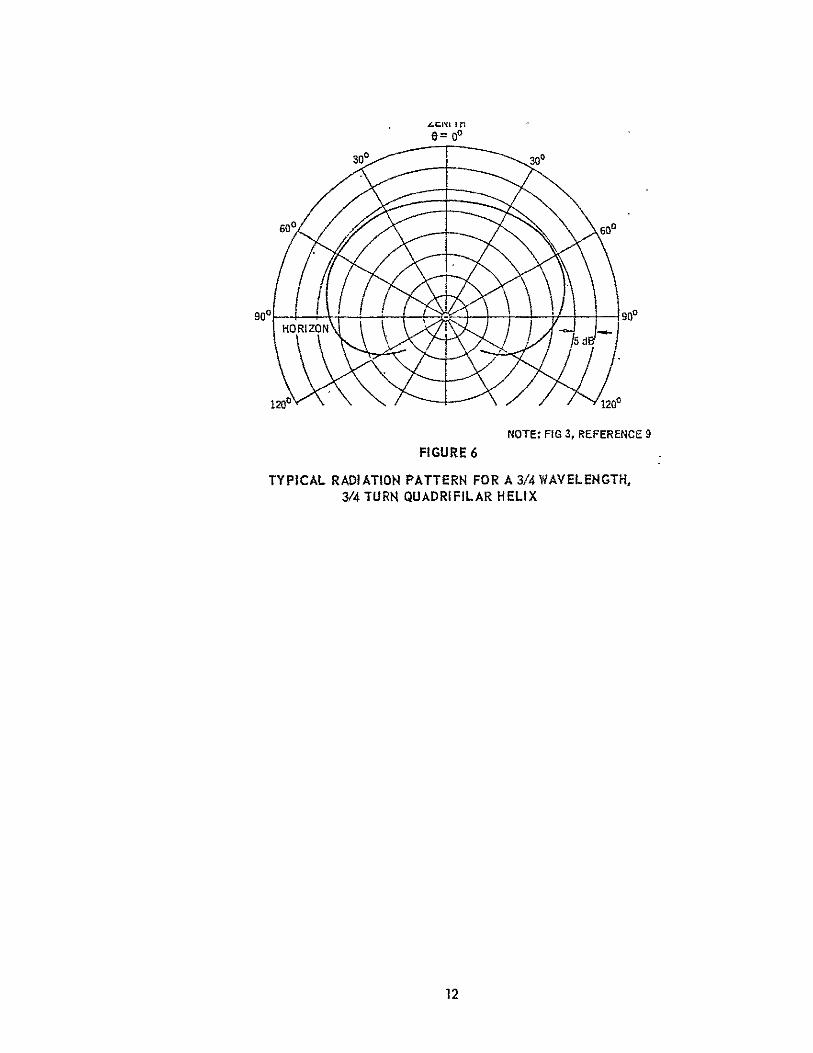
Quadrifilar helix antenna. - The quadrifilar helix antenna can takenumerous forms (References 3 thru 9). Of these 3/4 X - 3/4 turn version
was selected as a spacecraft receiving antenna candidate.(Reference 9) Figure 5 shows a sketch of this antenna configuration. The radiation patterns of a 3/4 A - 3/4 turn quadrifilar helix antenna (Reference 9) have a low axial
ratio and excellent pattern symmetry. This antenna may also be arrayed to
control the elevation pattern shape as demonstrated by a two element arraydesign described and supported by test data in Reference 9. Data from an arrayof two elements (Reference 9) shows a main beam symmetry of 1 dB peak to peakor less. Comparison of the expected radiation pattern (Figure 6), using thecalculated directivity and an estimated efficiency of -1.5 dB (71%), with
the required pattern (Reference 1) shows a positive performance margin of .09
dB at e = 32.50 and 1.51 dB at e-= 96.5'.
The volume required for this antenna is a cylinder 6.1 to 7.6 cm (2.4 to3.0 in.) in diameter and 38.6 cm (15.2 in.) long.
Antenna Selection'
The parameters used to evaluate and compare the performance of thecandidate antennas are summarized in Table I.
The Lindenblad antenna radiation pattern directivity iswell below(approximately 9.7 dB) that of the ideal antenna radiation characteristics.Calculations for two element arrays did not show any improvement. Further,
7
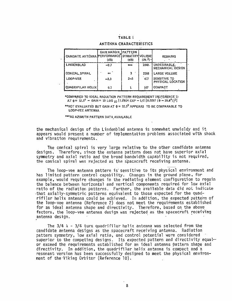
TABLE I
ANTENNA CHARACTEaISTICS
GAIN MARGIN PATTERN CANIDATE ANTENNA PERFOtAANCE SYMMETRV VOLUME REMARKS
(dB) (dB) (IN) -
LINDENBLAD -9.7 1040- UNDESIRABLE, MECHANICAL DESIGN
CONICALSPIRAL ** 3 2268 LARGE VOLUME
LOOP-VEE -3.3 2-3 477 SENSITIVE TO PHYSICAL LOCATION
QUADRIFILAR HELIX 0.1 1. 107 COMPACT
*COMPARED TO IDEAL RADIATION PATTERN REQUIREMENT (REFERENCE 1) AT 0 = 32.50 - GAIN = 10 LOG 10 1.t804 EXP - 1/2 (0.0297 (9 -- 39.61) 121
"NOT EVALUATED BUT GAIN AT 0 = 32.50 APPEARS TO BE COMPARABLE TO LOOP-VEE ANTENNA
***NO AZIMUTH PATTERN DATA AVAILABLE
the mechanical design of the Lindenblad antenna is somewhat unwieldy and itappears would present a number of implementation problems associated with shockand vibration requirements.
The conical spiral is very large relative to the other candidate antennadesigns, Therefore, since-the antenna pattern does not have superior axialsymmetry and axial ratio and the broad bandwidth capability is not required,the conical spiral was rejected as the spacecraft receiving antenna.
The loop-vee antenna pattern is sensitive to its physical environment andhas limited pattern control capability. Changes in the ground plane, forexample, would require changes in the radiating element configuration to regainthe balance between horizontal and vertical components required for low axialratio of the radiation patterns. Further, the available data did not indicate-that axially-symmetric patterns equivalent to those expected .for the quadrifilar helix antenna could be achieved. In addition, the expected pattern ofthe loop-vee antenna (Reference 2) does not meet the requitements establishedfor an ideal antenna shape and directivity. Therefore, based on the abovefactors, the loop-vee antenna design was rejected as the spacecraft receivingantenna design.
The 3/4 X - 3/4 turn quadrifilar helix antenna was selected from thecandidate antenna designs as the spacecraft receiving antenna. Radiationpattern symmetry, low axial ratio, and control potential were consideredsuperior to the competing designs. Its expected pattern and directivity equalor exceed the requirements established for an ideal antenna pattern shape anddirectivity. In addition, the quadrifilar helix antenna is compact and aresonant-version has been successfully designed to meet the physical environment of the-Viking Orbiter (Reference 10).
B
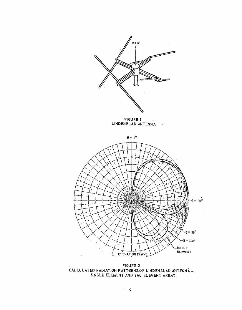
FIGURE 1LINDENBLAD ANTENNA
o = o
3= goo
- .j 1200
ELEMENT•AELEVAT ON-r--PLANE,
FIGURE 2 CALCULATED RADIATION PATTERNSOF LINDENBLAD ANTENNA -
SINGLE ELEMENT AND TWO ELEMENT ARRAY
9
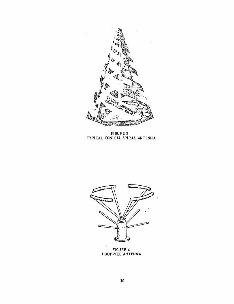
FIGURE 3TYPICAL CONICAL SPIRAL ANTENNA
FIGURE 4LOOP-VEE ANTENNA
*10

o =00
'-- 0.1 A0 STYROFOAM FORn TO SUPPORT HELIX ELEMENTS
I'~ -'BALUN
I WRAP LENGTH \\ - 3/4 TURN
LENGTH IS (PITCH DETERMINED FUNCTION OF BY ELEMENT LENGTH-PARTICULAR r 1 MINUS RADIAL)TO BALUN DESIGN " , M R T
nJI
k :Ii! ,. 0l ELEMENTLENGTH
ELEMENT LENGTH -0.75IL, S ELEMENT WIDTH/DIAMETER
HELIX ELEMENT l0.02 Xo =
TERMINATION ON I1 NOTE: (Ao CENTER FREQ. SUPPORT FORM 11 WAVELENGTH) IS OPEN CIRCUIT
TO 900 HYBRID
FIGURE 5 QUADRIFILAR HELIX ANTENNA
3/4 WAVELENGTH, 3/4 TURN
11
oe= o 300 300
NOTE: FIG 3, REFERENCE 9 FIGURE 6
TYPICAL RADIATION PATTERN FOR A 3/4 WAVELENGTH, 3/4 TURN QUADRIFILAR HELIX
12
MODEL ANTENNA TESTS
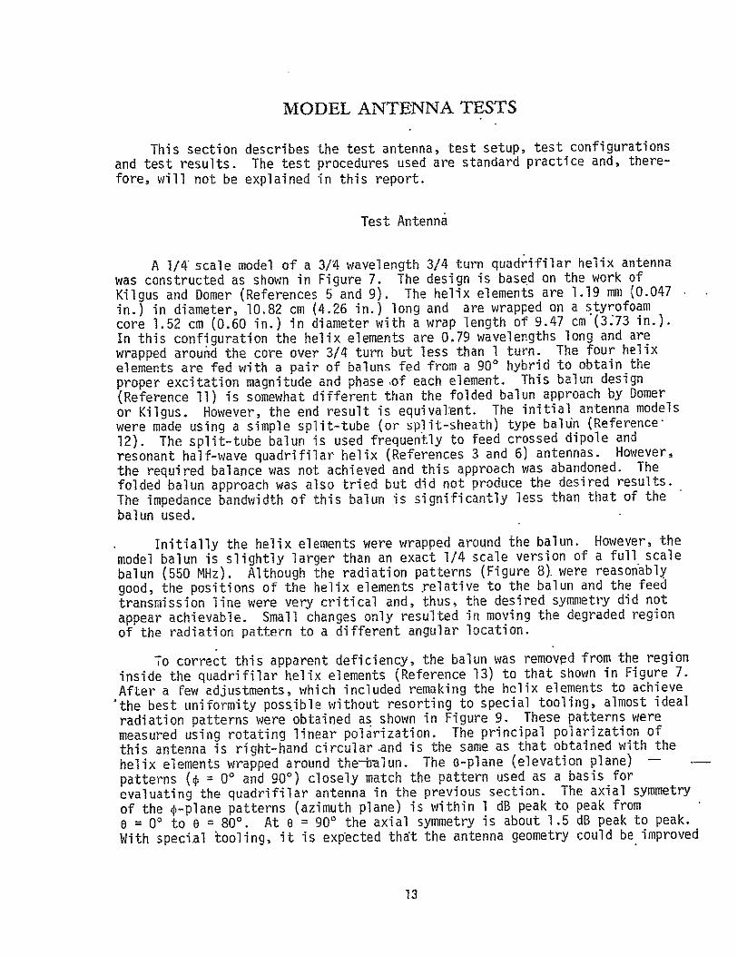
This section describes the test antenna, test setup, test configurationsand test results. The test procedures used are standard practice and, therefore, will not be explained in this report.
Test Antenna
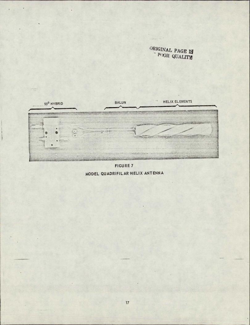
A I/ scale model of a 3/4 wavelength 3/4 turn quadrifilar helix antennawas constructed as shown in Figure 7. The design is based on the work ofKilgus and Domer (References 5 and 9). The helix elements are 1.19 mm (0.047in.) in diameter, 10.82 cm (4.26 in.) long and are wrapped on a styrofoamcore 1.52 cm (0.60 in.) in diameter with a wrap length of 9.47 cm*(373 in.).Inthis configuration the helix elements are 0.79 wavelengths long and arewrapped around the core over 3/4 turn but less than 1 turn. The four helixelements are fed with a pair of baluns fed from a 900 hybrid to obtain theproper excitation magnitude and phaseof each element. This balun design(Reference 11) is somewhat different than the folded balun approach by Domeror Kilgus. However, the end result is equivalent. The initial antenna modelswere made using a simple split-tube (or split-sheath) type baldn (Reference12). The split-tube balun is used frequently to feed crossed dipole andresonant half-wave quadrifilar helix (References 3 and 6) antennas. However,the required balance was not achieved and this approach was abandoned. Thefolded balun approach was also tried but did not produce the desired results.The impedance bandwidth of this balun is significantly less than that of thebalun used.
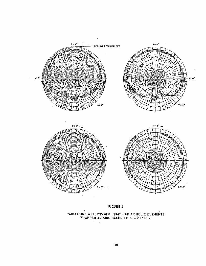
Initially the helix elements were wrapped around the balun. However, themodel balun is slightly larger than an exact 1/4 scale version of a full scalebalun (550 MHz). Although the radiation patterns (Figure 8). were reasonablygood, the positions of the helix elements relative to the balun and the feedtransmission line were very critical and, thus, the desired symmetry did notappear achievable. Small changes only resulted in moving the degraded regionof the radiation pattern to a different angular location.
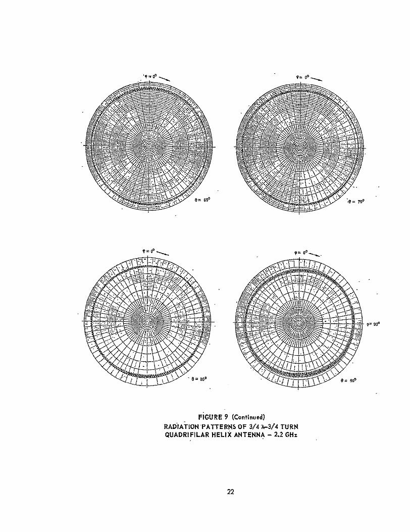
To correct this apparent deficiency, the balun was removed from the regioninside the quadrifilar helix elements (Reference 13) to that shown in Figure 7.After a few adjustments, which included remaking the helix elements to achieve'the best uniformity possible without resorting to special tooling, almost idealradiation patterns were obtained as shown in Figure 9. These patterns weremeasured using rotating linear polarization. The principal polarization ofthis antenna is right-hand circular.and is the same as that obtained with thehelix elements wrapped around the-dijun. The e-plane (elevation plane)
patterns (. = 0' and 90°) closely match the pattern used as a basis forevaluating the quadrifilar antenna in the previous section. The axial symmetryof the p-plane patterns (azimuth plane) is within 1 dB peak to peak fromo = 00 to e = 800. At e = 900 the axial symmetry is about 1.5 dB peak to peak.
With special tooling, it is expected that the antenna geometry could be improved
13

enough to achieve an axial symmetry of 1 dB peak to peak or less. The worstaxial ratio from e = 00 to e = 90 is about 2.5 dB at e = 90'. From a = 00 to 6 = 800 the axial ratio varies from 0 dB (or verylow) to about 1.5 dB. From S = 900 to 0 = 1200 the worst axial ratio is only about 5 dB. The peakdirectivity (circular polarization) of the model antenna is 3.7 dB and thepeak gain is 0.5 dB compared to a standard gain horn (Scientific Altantic -SGH 1.7). The efficiency (directivity/gain) is 48% (-2.2 dB). The lowefficiency is due to the increased losses of the coax used at the frequency-fthe model antenna designs (2.2 GHz). The efficiency at full scale (550 MHz)is expected to be about 71% (-1.5 dB) (Reference 14). With the improvedefficiency the expected peak gain of a full scale antenna would be 2.2 dB.
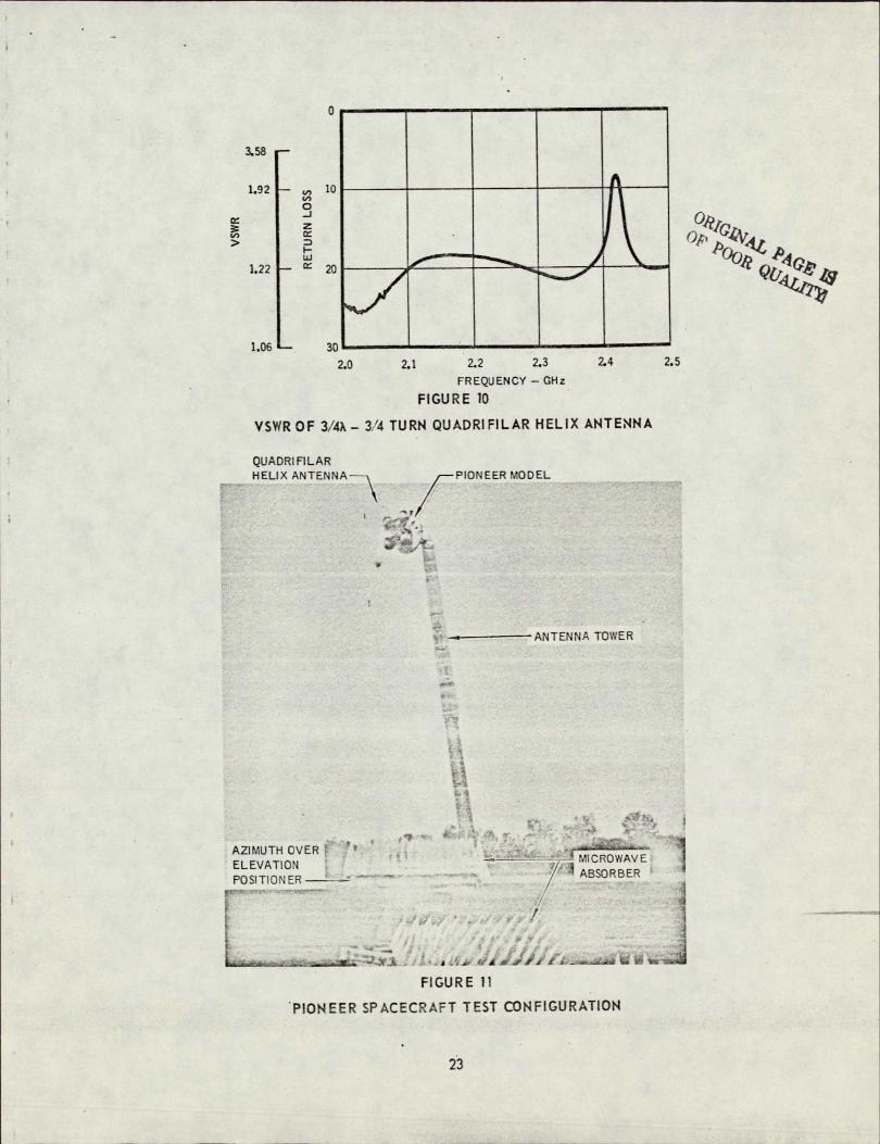
The voltage standing wave ratio (VSWR) of the model antenna is shown inFigure 10. It was measured with an HP Network Analyzer system. The VSWR isabout 1.29:1 at 2.2 GHz and improves at both higher and lowerfrequencies. Thehighest VSWR is 2.32:1 at 2.42 GHz and would be quite acceptable.
The radiation pattern and VSWR data described above demonstrates the merits of the quadrifilar helix as an axially symmetric antenna for a spacecraft receiving antenna. Both symmetry and axial ratio are excellent. Therefore, the performance of this antenna should be more than adequate to evaluatethe effects of the Pioneer spacecraft on the symmetry of its radiation pattern.
Test Setup
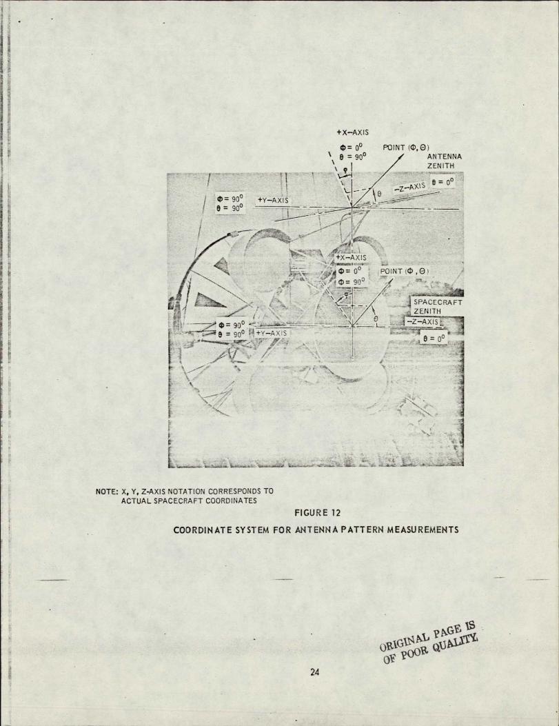
The test setup consisted of the Pioneer spacecraft model mounted on anantenna pattern tower, Figure 11, which supports the spacecraft spin axis7.3 m (24 ft) above the ground. Figure 12 shows the coordinate system,relative to the spacecraft, used for measuring the radiation patterns. Thiscoordinate system corresponds to that used for the model antenna design tests and permits direct comparison of patterns with similar coordinate designations., In this test setup, the probe can be rotated about its axis to measure conical plane (or roll plane)patterns (i-plane, i.e., e fixed and 4 variable) from o = 0' to 0 - 180', or it can be held in a fixed rotational position (e.g.,4 = 00 or 4 = 900) and the tower rotated to measure elevation plane patterns(0-plane, i.e., * fixed and o variable) which include the spacecraft axis ofsymmetry. The radiation patterns were measured using a rotating linearpolarization with a transmission distance of 11.9 m (39 ft). The VSWR was 'measured using a HP slotted line, a HP 415 Standing Wave Indicator and a HP616 B Signal Generator.
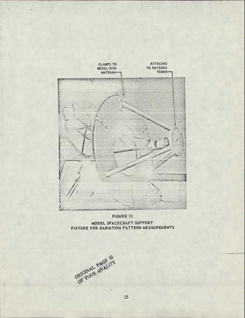
The Pioneer spacecraft model was attached to the antenna tower by meansof a support fixture clamped to the dish antenna (Figure 13). The circularplate just beyond the dish antenna feed mates with the antenna tower arborplate. This mounting arrangement takes advantage of the shadowing from thedish antenna and should minimize the effects of the tower and tower head.
14

Test Configurations
Four antenna locations were tested which essentially bracket the range offeasible locations.
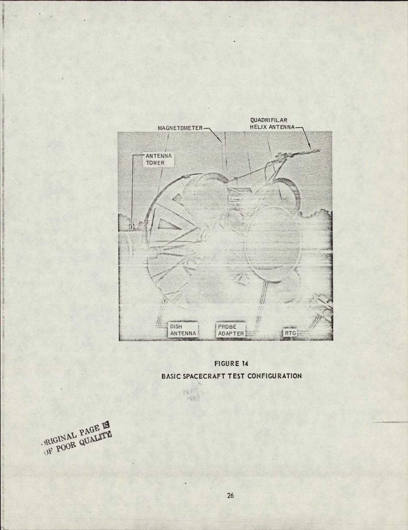
Configuration No. 1. - The basic test configuration was the quadrifilarhelix antenna mounted on the Pioneer spacecraft as shown in Figure 14; Thisconfiguration places the antenna essentially at the position established fora loop-vee antenna (Reference 14) by previous studies. The outer end ofquadrifilar helix antenna extends aft of the probe adapter ring 98 cm (38.6 in.)compared to 58.4 cm (23 in.) (Note: full scale dimensions) for the loop-veeantenna configuration. This antenna location places-the inner end of theantenna about 1/4 X from the junction of the tripod which supports the antennaon the spacecraft.
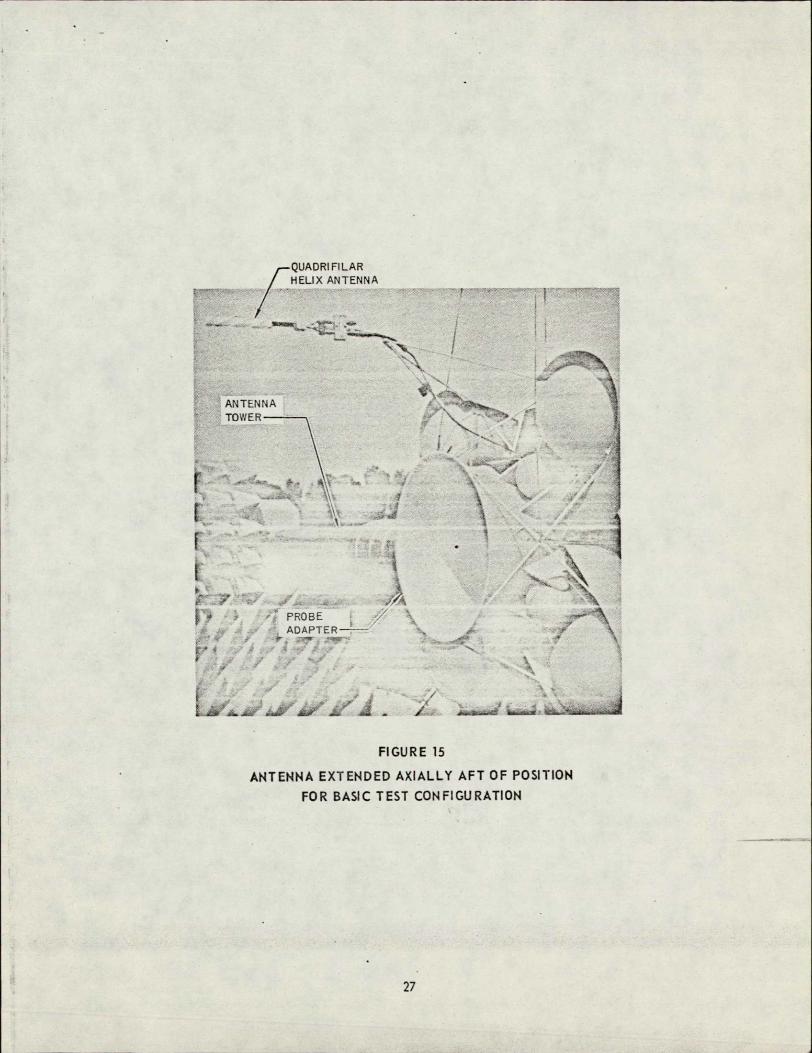
Configuration No. 2. - This configuration(Figure 15) consists of extending the end of the quadrifilar helix antenna to 1.42 m (56.0 in.) aft of theprobe adapter ring. This keeps the antenna outside an 180 (half angle) probelaunch clearance-cone established in Reference 2. This configuration would beexpected to produce some improvement in patterns because the reflected energy from the spacecraft would be received at a slightly lower gain level. Thehardware required to extend the antenna for this configuration would increasethe spacecraft weight about 0.60 kg (1.32 ibs).
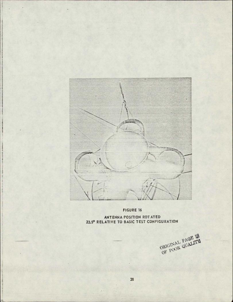
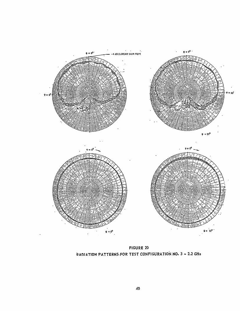
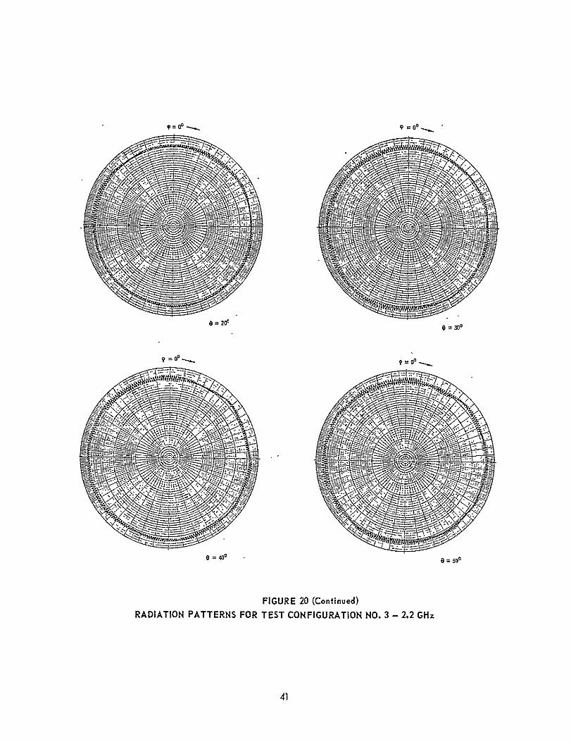
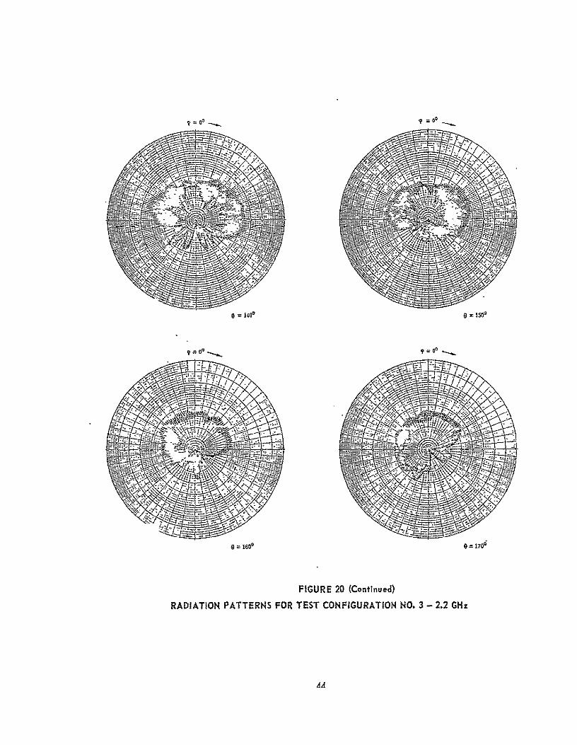
Configuration No. 3. - This configuration (Figure 16) is similar to thatof No. 1 with the antenna location rotated 22.50 (same radius) to place theantenna directly over one of the four tanks clustered around the probe adapter. This location provides the antenna with a different view of thespacecraft.
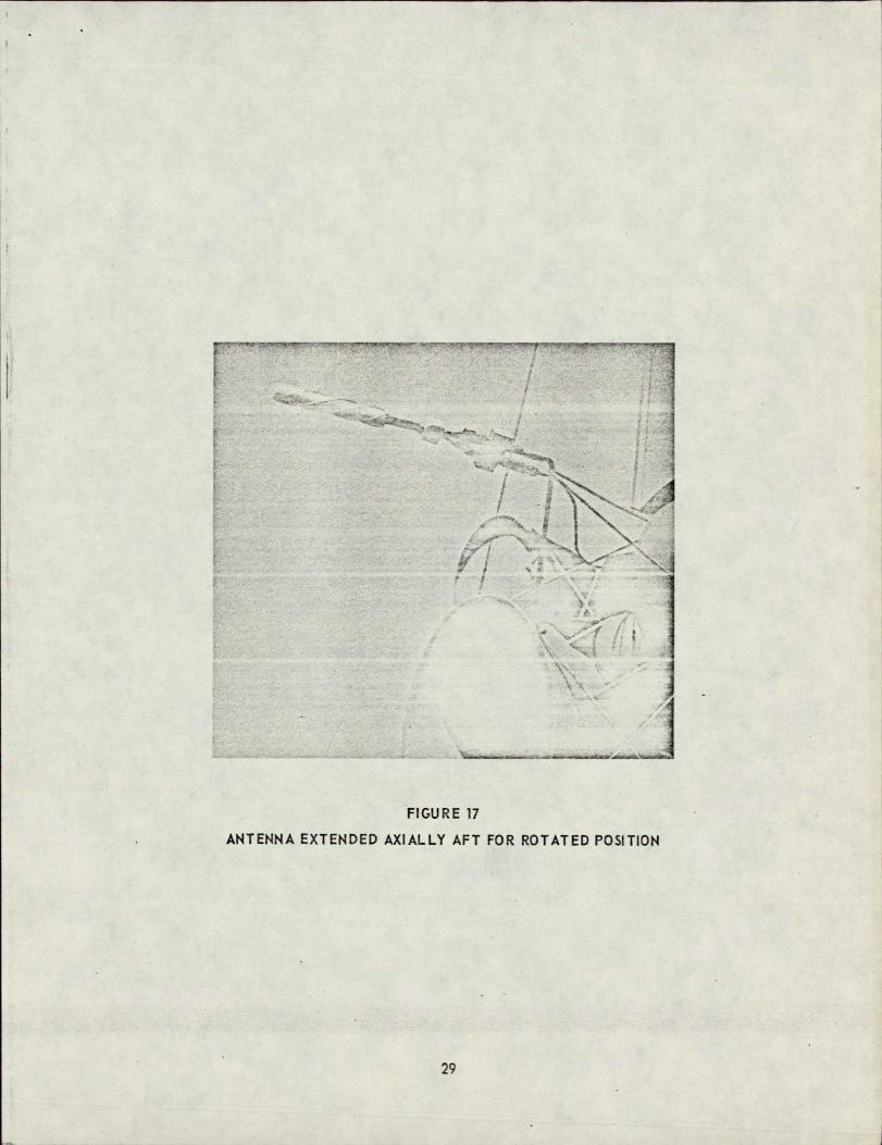
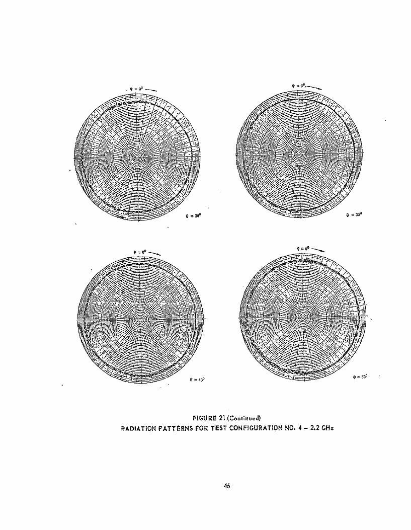
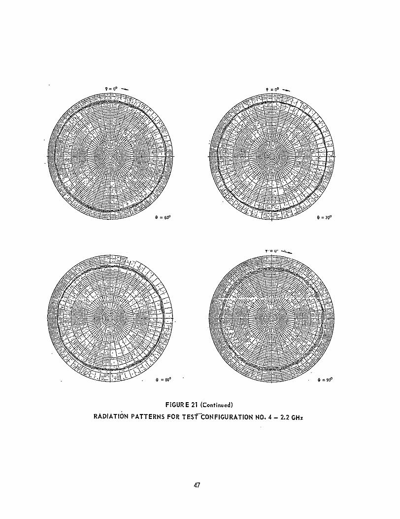
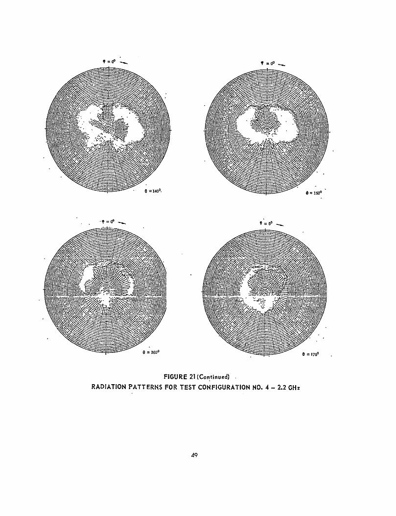
Configuration No. 4. - This configuration (Figure 17) extends the antenna,above the adapter ring essentially the same as Configuration No. 2 but with therotated location selected for Configuration No. 3. This configuration wouldincrease the spacecraft weight about the same as for Configuration No. 2, about0.60 kg (1.32 Ibs).
Test Results
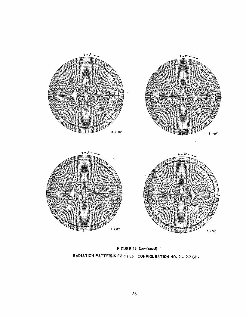
Ratiation Patterns. - The radiation patterns of the respective testconfigurations are shown in Figures 18 through 21: The pattern measurement frequency was 2.2 GHz which corresponds to 550 MHz at full scale. A comparisonof these patterns with the basic ante=nna patterns (Figure 9) shows the effectsof reflections from various parts of the spacecraft. However, the patternchanges are not large enough to identify a particular spacecraft appendage(for example, the magnetometer or RTG's) or structural -feature as the cause.The axial ratio changes (0 to approximately ±2 dB) can be attributed to ageneral reflection level from the spacecraft of 15 to 30 dB below the directlyreceived level. A summary of roll plane pattern dissymmetry (peak to peak) and
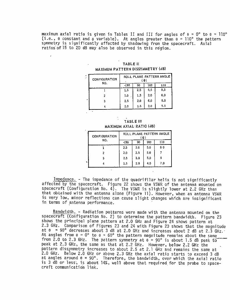
maximum axial ratio is given in Tables II and III for angles of e = 00 to e = 1100(i.e., o constant and variable). At angles greater than 0 = l100 the patternsymmetry is significantly affected by shadowing from the spacecraft. Axialratiosof 15 to 20 dB may also be observed in this region.
TABLE IIMAXIMUM PATTERN DISSYMMETRY (dB)
ROLL PLANE PATTERN ANGLE CONFIGURATION (9)
NO. <80 90 100 110
1 1.5 2.5 5.5 9.5
2 1.0 . 1.5 2.0 6.0
3 2.5 2.0 6.0 8.0
4 2.0 1.5 2.0 5.5
TABLE III MAXIMUM AXIAL RATIO (dB)
ROLL PLANE PATTERN ANGLE CONFIGURATION (9)
NO. <80 [ 90 100 110
1 2.5 3.0 5.0 80
2 2.0 2.5 5.0 7
3 2.3 3.0 5.0 9
4 1.5 2.0 4.0 7.0
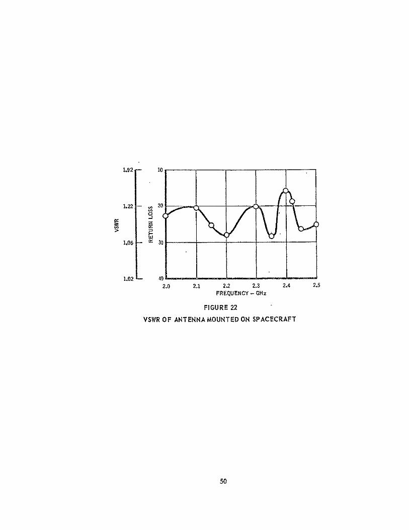
Impedance. - The impedance of the quadrifilar helix is not significantly affected by the spacecraft. Figure 22 shows the VSWR of the antenna mounted on spacecraft (Configuration No. 4). The VSWR is slightly lower at 2.2 GHz than that obtained with the antenna alone (Figure II). However, when an antenna VSWR is very low, minor reflections can cause slight changes which are insignificant in terms of antenna performance.
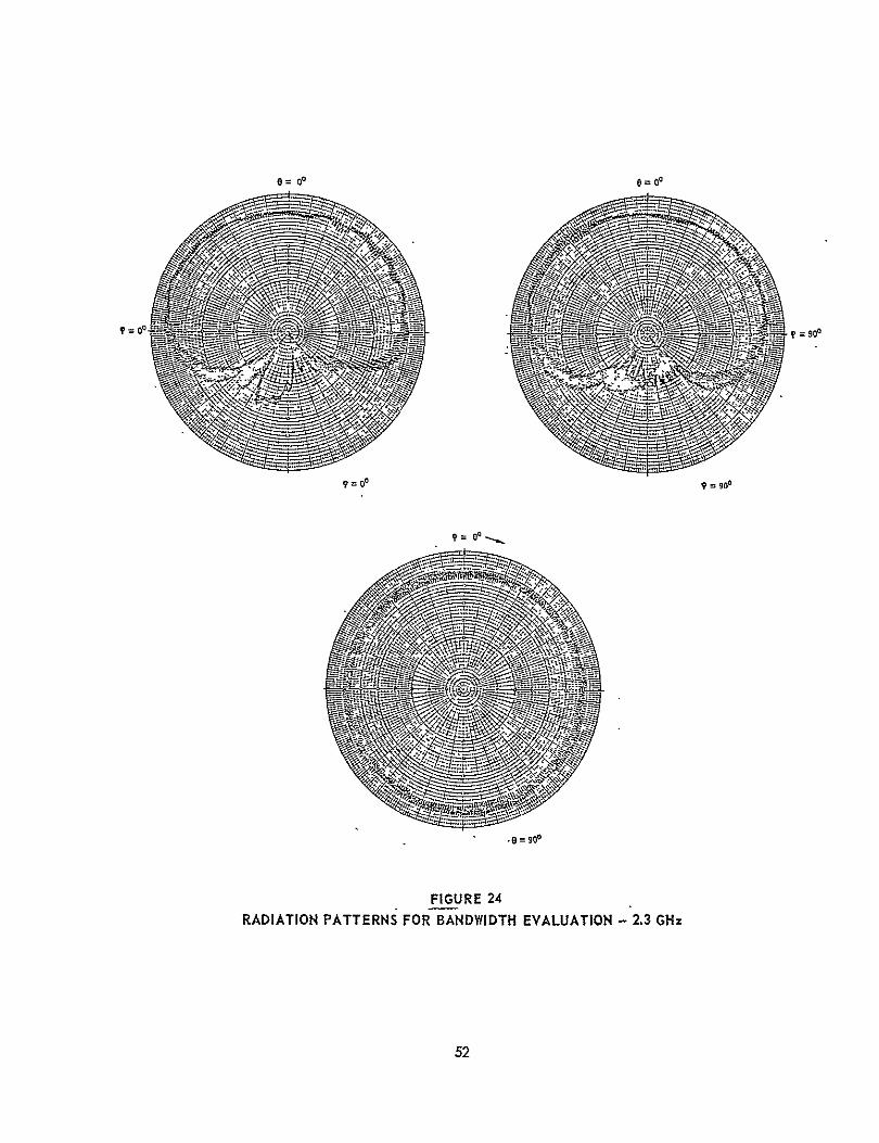
Bandwidth. - Radiation patterns were made with the antenna mounted on thespacecraft Configuration No. 2) to determine the pattern bandwidth. Figure 23shows the principal plane pattern at 2.0 GHz and Figure 24 shows pattern at2.3 GHz. Comparison of Figures 23 and 24 with Figure 20 shows that the magnitudeat 0 = 900 decreases about 3 dB at 2.0 GHz and increases about 2 dB at 2.3 GHz.-At angles from e = 00 to a = 600 the pattern magnitude remains about the samefrom 2.0 to 2.3 GHz. The pattern symmetry at e = 900 is about 1.5 dB peak t6_peak at 2.3 GHz, the same as that at 2.2 GHz. However, below 2.2 GHz thepattern dissymmetry increases to about 2.5 at 2.1 GHz and remains the same at2.0 GHz. Below 2.0 GHz or above 2.3 GHz the axial ratio starts to exceed 3 dBat angles around e = 900. Therefore, the bandwidth, over which the axial ratiois 3 dB or less-, is about 14%, well above that required for the probe to spacecraft communication link.
O)RIcwAL PAGEk IS
POOR QUALrr
HELIX ELEMENTSBALUN900 HYBRID
FIGURE 7
MODEL QUADRIFILARIHELIX ANTENNA
17
1.5dB (UNEAR GAIN REF.)
RADIATION PATTERNS WIlTH QUADRIFILAR HELIX ELEMENTSWRAPPED AROUND BALUN FEED - 2.17 GHz
18

0=SQ O=s
470 sop0~~
FIGURE 8 (Continued) RADIATION PATTERNS WITH QUADRIFLIAR HELIX ELEMENTS
WRAPPED AROUND BALUNFEED - 2.17 GHz
19

= 0e -0 -2.5 dB (UNEAR GAIN REF)
-=00 ,- .o ,
ft/ O0
FIGURE 9
RADIATION P.ATTERNS OF 3/4 A-3/4 TURNQUADRIFILAR HELIX ANTENNA - 2.2 GHz
90

23Q
FIGURE 9 (Continued)
RADIATION PATTERNS OF 3/4 X-3/4 TURN QUADRIFILAR HELIX ANTENNA - 2.2 GHz
21
-"
FiGURE 9 (Continued)RADIATION PATTERNS OF 3/4 i6-3/4 TURNQUADRIFILAR HELIX ANTENNA - 2.2 GHz
22
0
1.92 1
>~op I-.I L.22 - DO2
2.0 2.1 2.2 2.3 2.4 2.5 FREQUENCY - GHz
FIGURE 10
VSWROF 3/4- 3/4 TURN QUADRIFILAR HELIX ANTENNA
QUADRI FILARHEUX ANTENNA- PIONEER MODEL
S . ANTENNA TOWER
AZIMUTH OVER ELEVATION ELEVATIONa -- MICR WAVE
POABSORBER
FIGURE 11
PIONEER SPACECRAFT TEST CONFIGURATION
23
+X-AXIS
=e00 POINT (0.E)\ e0 I ANTENNA
} ! EN ITH
I0
/ =goo +Y-Axis
NI Y4k0 POINT (0, 0) A
I= -e9t I.~ -- "I ZAX15 ATAPtjF SPACECRAFTo900M+Y-AXIS
NOTE: X. Y, Z-AXIS NOTATION CORRESPONDS TO ACTUAL SPACECRAFT COORDINATES
FIGURE 12
COORDINATE SYSTEM FOR ANTENNA PATTERN MEASUREMENTS
24
CLAMPS TO ATTACHES MODEL DISH TO ANTENNA
ANTENNA TOWER
7AA
FIGURE 13
MODEL SPACECRAFT SUPPORTFIXTURE FOR RADIATION PATTERN MEASUREMENTS
25
QUADRIFILAR
MAGNETOMETER HELIX ANTENNA
"ANTENNA.
DISH |PROBE i 'I=-' . ANTENNAf AAPTE',R'. n " .
FIGURE 14
BASIC SPACECRAFT TEST CONFIGURATION
26
QUADRIFILAR HEUX ANTENNA
PROBE I
ADAPTER--
FIGURE 15
ANTENNA EXTENDED AXIALLY AFT OF POSITION
FOR BASIC TEST CONFIGURATION
27
f4
,~~ 7x +.
FIUR 16
ANTENN POSITONROATE
CNIU A25REATVTOBSCET
I; INo OYV9A
fv
28A
.., "77. - %
FIGURE 17
ANTENNA EXTENDED AXIALLY AFT FOR ROTATED POSITION
29

8= 400 =so
FIGUREJ8 (Continued)
RADIATION PATTERNS FOR TEST CONFIGURATION NO. 1 - 2,2 GHz
31

0~ =up, °
FIGURE 18 (Continued)
RADIATION PATTERNS FOR TEST CONFIGURATION NO. I 2.2 GHz
32

9= , 00
V= 000
FIGURE 18 (Continued)
RADIATION PATTERNS FOR TEST CONFIGURATION NO. I - 2.2 GHz
33
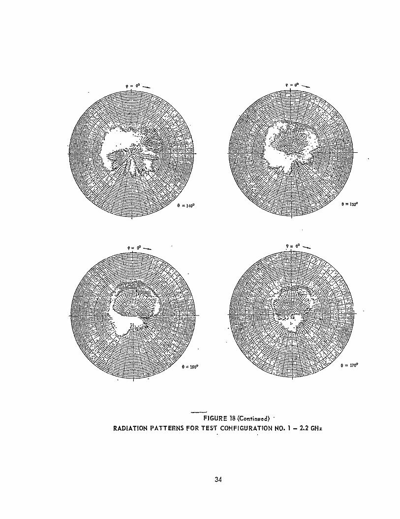
FIGURE 18 (Continued)
RADIATION PATTERNS FOR TEST CONFIGURATION NO.1 - 2.2 GHz
34

-525 dBIUNEAR GAIH REF.)
' op 9 go -
FIGURE'19 RADIATION PATTERNS FOR TEST CONFIGURATION NO. 2. - 2.2 GHz
35
8 00 0
200 0 =300
FIGURE 19 (Continued) RADIATION PATTERNS FOR'TEST CONFIGURATION NO. 2 2.2 GHz
36

°0 =60 O
FIGURE 19 (Continued)
RADIATION PATTERNS FOR TEST CONFIGURATION NO. 2 - 2.2 GHz
37

-4--'.,-~~ -s.1 -- 1&
FIGURE 19 (Continued) RADIATION PATTERNS FOR TEST CONFIGURATION NO. 2 - 2.2 GHz
38

-.- e =140°
e -1500
1600 8 1700
FIGURE 19 (Continued)
RADIATION PATTERNS FOR TEST CONFIGURATION NO. 2 - 2.2 GHz
39
= o -4dBMO° -4 dB,(LNEAX GAiN flEF) 4
9.09
FIGURE 20 RAnIATIOW PATTERNSPFOR TEST CONFIGURATION NO. 3 - 2.2 GM:
40
9 20' 9 300
9 43039 0
my,
FIGURE 20 (Continued)RADIATION PATTERNS FOR TEST CONFIGURATION NO.3 - 2.2 GHz
41

oSoo 70
oe=80 - -=.0
FIGURE 20 (Continued)
RADIATION PATTERNS FOR TEST CONFIUUKAIIUN NU. I Z.L Ur1z
42

o 1~' 0 130'
FIGURE 20 (ContinueOd)
RADIATION PATTERNS FOR -TEST CONFIGURATION NO. 3 - 2.2 GH:
43
0= 1706S=160
FIGURE 20 (Continued)
RADIATION PATTERNS FOR TEST CONFIGURATION NO 3 - 2.2 GHz
AA

-4dB (LINEAR GAIN REF) 00
9op
RADIATION
° 0 =o
FIGURE 21 PATTERNS FOR TEST CONFIGURATION NO. 4 2.2 GHz
10.
45
-- 40 0-5
FIGURE 21 (Continued)
RADIATION PATTERNS FOR TEST CONFIGURATION NO. 4 - 2.2 GHz
46
99 =00
-. A
FIGURE 21 (Continued)
RADIATION PATTERNS FOR TEST CONFIGURATION NO. 4 - 2.2 GHz
47

e~l~o 1300
FIGURE 21 (Continued)
RADIATION PATTERNS FOR TEST CONFIGURATION NO. 4 - 2.2 GHz
48
0 ? 9=00
.°
e=1600 0 1700
FIGURE 21 (Continued)
RADIATION PATTERNS FOR TEST CONFIGURATION NO. 4 - 2.2 GHz
4'9
1.92 10
1.22 20
1.02 - 4 2.0 M. 2.2 2.3 2.4
FREQUENCY - GHz
FIGURE 22 VSWR OF ANTEMNAMOUNTED ON SPACECRAFT
2.5
50

8= O0 8-00
00 -T=o
9=0 o 9=990
0090 go
-90
FIGURE 23
RADIATION PATTERNS FOR BANDWIDTH EVALUATION - 20 GHZ
51"
6=00 009
=00 9 =goo
ogo
FIGURE 24 RADIATION PATTERNS FOR BANDWIDTH EVALUATION - 2.3 GHz
52

CONCLUSIONS
A quadrifilar helix antenna has been selected for the Pioneer spacecraft. A 1/4 scale model of the quadrifilar helix antenna was constructed and tested. The results of these tests, radiation pattern and VSWR measurements, show that this antenna has excellent pattern symmetry, 1.5 dB peak to peak compared to a goal of 1 dB from e = 00 to e = 90' and an axial ratio maximum of 2.5 dB over the same angular region. Over much of this region the axial ratio is 0.5 dB or less. To improve on these results, it is believed that use of special precision tooling would be required-during the construction process to control the geometry of the quadrifilar helix elements more -precisely. Based on these test results, it can be concluded that the model antenna performance is ideal for evaluating the effects of the spacecraft on the axial symmetry of a receiving antenna.
The results of the radiation pattern measurements show that the antennalocation is not critical. Over the aft hemisphere (9 = 00 to e = 90) theworst pattern symmetry is 2.5 dB peak to peak and the maximum axial ratio is3 dB or less for all of the configurations tested. However, the patternsymmetry and axial ratio of the radiation patterns is improved-with the antennaslocated as far from the spacecraft-as possible.
The test results show that the spacecraft has no significant effect on theantenna impedance (VSWR) or bandwidth. Based on the test results obtainedduring this study, it is concluded that the quadrifilar helix antenna willprovide radiation patterns with good symmetry and low axial ratios at spacecraftlook angles over the aft hemisphere. The peak circular gain of the quadrifilarhelix antenna, when scaled to 550 MHz, should be about 2.2 dB based on anexpected efficiency of 71% (-1.5 dB) at the larger size..
53

REFERENCES
1. Hinrichs, C. A.: McDonnell Douglas Astronautics Company-East: "Preentry --Communications Study for Outer Planets Atmosphere Entry Probe", NASACR 137876, May 1976.
2. TRW Systems Group: Saturn Uranus Atmsopheric Entry Probe Mission Space-Craft System Definition Study. Final Report, Contract NAS 2-7297.15 July 1973.
3. Kilgus, C. C.: "Multielement Fractional Turn Helicies", IEEE Transactionson Antennas and Propogation, Vol. AP-16, July 1968, pp 499-501.
4. Kilgus, C. C.: "Resonant Quadrifilar Helix", IEEE Transactions on Antennas
and Propogation, Vol. AP-17, May 1969, pp 349-351.
5. Kilgus, C. C.: "Resonant Quadrifilar Helix Design", Microwave JournalVolume 13-12, December 1970, pp 49-54.
6. Kilgus, C. C.: "Spacecraft and Ground Station Applications of the ResonantQuadrifilar Helix", Digest of the 1974 International IEEE/AP-S Symposium,June 1974, pp 75-77.
7. Bucker, R. W., and Rickert, H. H.: "An S-Band Resonant Quadrifilar Antennafor Satellite Communication", Digest of the 1974 International IEEE/AP-SSymposium, June 1974, pp 78-82.
8. Kilgus, C. C.: "Shaped-Conical Radiation Pattern Performance of the BackfireQuadrifilar Helix", IEEE Transactions on Antennas and Propogation, AP-23,May 1975, pp 392-396.
9. Domer, F. R.: "Two-Element Quadrifilar Array, Naval Research Laboratory,NRL Report 7661, 8 March 1.974.
10. Frank, P. D.: Philco Ford Corporation, "Viking Orbiter 1975 AntennaSubsystems, Relay Antenna", Volume-3, JUP SubcontractNo. 953379,15 February 1974.
11.. Roberts, W. K.: "A New Wide-Band Balun", Proceedings of the IRE, pp 16281631, December 1957.
12. Jasik, H. (Editor): Antenna Engineering Handbook, McGraw-Hill Book Company, New York, 1961, pp 31-22 - 31-25
13. Shields, M. W.: "Final Report on SAS-C S-Band Antenna" Applied PhysicsLaboratory, Memo No. $2T-4-123, 31. January 1975.
14. C. C. Kilgus: Private Communi.cation..
?PMKWMNG PAGE BLANK NOT F1IIME
55

ACKNOWLEDGEMENTS
The author expresses his appreciation to E. D. McKee and R. M. Ousley ofthe McDonnell Aircraft Company Microwave Antenna Laboratory Staff for thefabrication and detailed modifications to the quadrifilar helix antenna modeland the radiation pattern and impedance measurements:
"""Q PA9I PLANK NoT PM)"
57