5 Highly Conductive Plastics – Custom-formulated ... · 5.2 Characteristics of the Hybrid...
14
43 5 Highly Conductive Plastics – Custom-formulated Functional Materials for Injection Mouldable Electronic Applications Walter Michaeli, Tobias Pfefferkorn and Jan Fragner 5.1 Introduction Electric and electronic products have gained increasing importance in a number of industries. Becoming ever more complex, they are being used in highly integrated assembly groups. In addition, there is a growing trend for miniaturisation, particularly in the fields of electronics, electrical engineering, communications engineering and automotive engineering [1]. Conductive components in electric and electronic products have to fulfil different requirements depending on their field of application. For example, a very high electrical conductivity is needed for plug-in connections, elements in transmission and engine control systems. Defined ranges of conductivity are required for control units, sensors and enclosures. For the latter application, electromagnetic shielding is also of importance. Lower electrical conductivity values are demanded for applications that have to prevent electrostatic charge. Polymers are typical insulation materials due to their extremely low electrical conductivity. Interest in using polymers for other electrical applications has increased due to advantageous properties such as weight, processibility and resistance to chemicals. Over the years, thermally and electrically conducting polymers have been developed by the addition of common fillers such as carbon black, graphite, metallic fibres, flakes or carbon fibres and, increasingly, nano-fillers such as carbon nano-tubes. These compounds have already been deployed successfully in a range of antistatic and electromagnetic shielding applications. In order to ensure a high degree of electrical conductivity, a high content of conductive fillers is required, which forms a close percolation network [2, 3]. For each material composition, a compromise has to be found regarding the amount of filler. Higher filler contents commonly have a negative influence on the mechanical properties and processability due to the considerable increase in melt viscosity.
Transcript of 5 Highly Conductive Plastics – Custom-formulated ... · 5.2 Characteristics of the Hybrid...

43
5 Highly Conductive Plastics – Custom-formulated Functional Materials for Injection Mouldable Electronic Applications
Walter Michaeli, Tobias Pfefferkorn and Jan Fragner
5.1 Introduction
Electric and electronic products have gained increasing importance in a number of industries. Becoming ever more complex, they are being used in highly integrated assembly groups. In addition, there is a growing trend for miniaturisation, particularly in the fields of electronics, electrical engineering, communications engineering and automotive engineering [1].
Conductive components in electric and electronic products have to fulfil different requirements depending on their field of application. For example, a very high electrical conductivity is needed for plug-in connections, elements in transmission and engine control systems. Defined ranges of conductivity are required for control units, sensors and enclosures. For the latter application, electromagnetic shielding is also of importance. Lower electrical conductivity values are demanded for applications that have to prevent electrostatic charge.
Polymers are typical insulation materials due to their extremely low electrical conductivity. Interest in using polymers for other electrical applications has increased due to advantageous properties such as weight, processibility and resistance to chemicals. Over the years, thermally and electrically conducting polymers have been developed by the addition of common fillers such as carbon black, graphite, metallic fibres, flakes or carbon fibres and, increasingly, nano-fillers such as carbon nano-tubes. These compounds have already been deployed successfully in a range of antistatic and electromagnetic shielding applications. In order to ensure a high degree of electrical conductivity, a high content of conductive fillers is required, which forms a close percolation network [2, 3].
For each material composition, a compromise has to be found regarding the amount of filler. Higher filler contents commonly have a negative influence on the mechanical properties and processability due to the considerable increase in melt viscosity.

44
Polymer Electronics – A Flexible Technology
Concurrently, the wear on machinery and mould is higher than for unfilled polymers. The material compositions used so far are unable to fulfil the demands of upcoming component functionality, particularly for thin-walled and miniaturised elements. Hence, functional components that require high electrical conductivity, are still typically produced in cost-intensive processing and assembly steps (e.g., insert moulding, hot stamping or metallising) [2, 4-7].
The filler content, and thus the electrical conductivity, can be increased significantly without decreasing the processability by using metal alloys that exhibit a low melting point [8-10]. These metal alloys are liquid in the processing phase and will not solidify before the cooling phase. This allows the production of complex moulded parts with definite electrical and thermal properties. As a result, material related disadvantages are reduced in comparison with highly filled moulding compounds.
The reference material under investigation consists of 15 wt% (56 vol%) polyamide 6 (PA6) (type 6NV12 by A. Schulman Inc, Akron, USA), 33 wt% of a low-melting tin/zinc alloy with a melting point of 199 °C and 52 wt% of fine copper fibres (average length: 0.65 mm, diameter: 35 µm), developed in cooperation with Siemens AG, Germany. This highly filled polymer/metal hybrid material allows passage conductivities of 105-7 × 10⁶ S/m and conductivities over the wall thickness of 103-105
Figure 5.1 Electrical conductivity in comparison to other materials and potential applications

45
Highly Conductive Plastics – Custom-formulated Functional Materials for Injection Mouldable Electronic Applications
S/m [10]. These values are comparable with conductivities of pure metals (Figure 5.1).
Thus, it becomes possible to produce conducting structures and junctions for plug-in connections and/or cables in a single processing step by means of an injection moulding process. Time-consuming joining and soldering processes can be avoided. Figure 5.1 shows some possible applications. Contact pins can be directly integrated into electrically conducting elements, and electromagnetic shielding, achieving modules that are more efficient at cooling devices and motors.
5.2 Characteristics of the Hybrid Compound Within the Injection Moulding Process
5.2.1 The Cavity Filling
The thermoplastic/metal compounds can be processed in conventional single or multi-component injection moulding processes. Due to the high metal content, the filling and freezing behaviour of the materials differs from that of unfilled thermoplastics. That is caused by both the solid and liquid filler. The tests were carried out using an injection moulding machine of the type Allrounder 320 S 500 - 150 (Arburg GmbH + Co KG, Lossburg, Germany), which has a screw diameter of 30 mm (L/D = 20). First, the effects on the flow properties of the new material are discussed, followed by the characterisation of local filler distribution. Unfilled and low-filled thermoplastics show a typical frontal flow during filling of the mould. This is typical for viscoelastic fluids, whereby a parabolic velocity profile is formed over the parts thickness [11, 12]. With increasing filler content, the velocity profile generally become more block-shaped [13-15]. These typical flow patterns can be determined by mould filling studies of unfilled PA6 and material exclusively filled with copper fibres (Figure 5.2). The evenness of the filling is slightly reduced by copper fibres due to the decreased melt elasticity. The highly filled thermoplastic/metal compound shows a significantly altered filling behaviour due to the high filler content of 85 wt%. Beside the significantly reduced melt elasticity of the compound; the rapid heat flow, increased thermal conductivity and the specific phase transition of the metal alloy are the main reasons for this behaviour.

46
Polymer Electronics – A Flexible Technology
5.2.2 The Morphological Structure
In addition to the flow behaviour, the morphological structure of the highly filled compound directly influences the property of the part being produced. The combination of copper fibres and metal alloys with low melting points forms a dense, three-dimensional metal network, as can be seen in Figure 5.3. The positive effect of the metal alloy can be demonstrated in a close up view of a cross section. Due to the fine dispersion of the alloy, and good affinity of copper fibres and alloy, the distance between metal particles can be significantly reduced. This explains the high passage conductivity observed in the range of 106 S/m (Figure 5.3). By contrast, polyamide exclusively filled with copper fibres achieved conductivity values that were approximately three powers of ten lower, even when the filling degree was the same.
Figure 5.3 also shows that there is no linear relationship between the quantity of filler content and conductivity. At a low filler content, the conductivity of the matrix polymer is dominant. With increasing fibre content, the contacts between the fibres increase and the specific conductivity escalates in a small window. The critical concentrations of volume required for this escalation – called the percolation threshold – range between 20-25 vol% for both the metal/thermoplastic hybrid material, and the polymer exclusively filled with copper. Above this concentration, the metal network becomes more dense to an extent where conductivity can be increased only marginally [3, 16-18].
Figure 5.2 Comparison of mould filling studies of different materials

47
Highly Conductive Plastics – Custom-formulated Functional Materials for Injection Mouldable Electronic Applications
5.2.3 Dependence of the Conductivity on Geometry, Material and
Process Condition
The measured conductivity is not constant and changes considerably if the resistance
is measured through the interior or over its thickness, thus including the surface.
Figure 5.3 Formation of a 3-dimensional network and the improved passage conductivity (CT = computed tomography)
Figure 5.4 Influence of the geometry (wall thickness) on the conductivity (h = wall thickness of the plate geometry shown in the figure on the right)
48
Polymer Electronics – A Flexible Technology
This is explained by the surface layer effect. Due to the flow conditions of solid filled polymers, the surfaces of the injection moulded parts contain hardly any filler material [17, 19]. This effect can be reduced significantly with a low-melting metal alloy but cannot be avoided completely. Further on, the conductivity depends on the flow path due to the flow conditions in the gating system and in the moulded part. Figure 5.4 shows that the electrical conductivity over the wall thickness rises almost linearly with increasing flow length, which correlates well with the local density of the part. Besides the increasing filler content, the outer layer effect is reduced towards the end of the flow path. The rate of increase varies depending on the geometry, the composition of the material and the process conditions. With an increasing plate thickness, the conductivity over the wall thickness shows less dependence on the part’s position.
Furthermore, the electrical properties can be adjusted by varying the matrix polymer and the filler distribution. Since the material concept allows for the use of almost any polymer matrix, the required material properties, for instance a high temperature resistance, can be provided by the use of polyphenylene sulfide (PPS) as a matrix polymer. The morphological structure, and thus the measured conductivity over the thickness, depend on the ratio of the melt temperatures and viscosities of both the polymer and metal alloy, whereas the passage conductivity is at a similarly high level of > 4 × 10⁵ S/m.
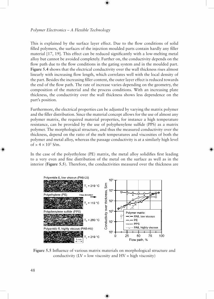
In the case of the polyethylene (PE) matrix, the metal alloy solidifies first leading to a very even and fine distribution of the metal on the surface as well as in the interior (Figure 5.5). Therefore, the conductivities measured over the thickness are
Figure 5.5 Influence of various matrix materials on morphological structure and conductivity (LV = low viscosity and HV = high viscosity)

49
Highly Conductive Plastics – Custom-formulated Functional Materials for Injection Mouldable Electronic Applications
Figure 5.6 Influence of the injection velocity on the electrical conductivity over the wall thickness
almost constant along the flow path. By contrast the polymer freezes first in the PPS compound. Thus, the pressure is transmitted by the metal alloy resulting in sizeable metal alloy agglomerates in the part’s centre and a high amount of the metallic phase that can be detected near the surface. Due to the big difference between polymer melting and mould temperature, the free flow cross-section decreases rapidly. This leads to a higher orientation of the filler material at the surface. The influence of the shear viscosity is analysed by comparing a low and highly viscous polyamide.
The latter shows very distinctive shear sections in the outer layers leading to conductivities over the thickness that are strongly dependent on the flow path. However, the viscosity itself has no significant influence on the distribution of the metal alloy. Freezing of the polymer at the same time or later than the metal alloy and a low viscosity of the material can considerably improve the level and homogeneity of conductivity.
The material properties are not only influenced by the composition of the material but also by the injection moulding process. Therefore, both the dosing and the injection parameters were systematically varied in the design of the experiments. The electrical passage conductivity is nearly constant in a broad process window due to the dense metallic network, whereas the conductivity measured over the thickness changes significantly by varying both the dosing and the injection parameters. For example, Figure 5.6 shows the influence of a low and high injection velocity on conductivity.

50
Polymer Electronics – A Flexible Technology
A lower injection velocity allows a longer filling phase, which reduces the formation of shear zones and hence improves the conductivity over the wall thickness.
5.2.4 Temperature Dependency on the Conductivity
Up to this point, the material properties have only been discussed at room temperature. However, in many fields of applications conductive polymers have to fulfil their functionalities (e.g., electrical conductivity) at elevated temperatures. In certain situations heating is produced from the outside, such as occur in ‘under the hood’ applications. Material warming can also occur under current load where the material is used as a conductor path in order to conduct electricity at a reasonably high current. In this process, the material is heated due to the electrical resistance of the material. It is important to consider if the conductive network would be damaged locally under thermal loading. Therefore, the time-dependent passage conductivity was determined by means of test specimens. The highest values measured at room temperature are slightly reduced until the glass transition temperature of polyamide (50-60 °C) is reached (Figure 5.7). Afterwards, the values remain constant at a high level and start decreasing at approximately 170 °C. The change in conductivity under heating is reversible, since the initial values are reached again after cooling.
The charging of samples with electric current leads to increasing material temperatures when choosing either smaller cross sections or higher currents (Figure 5.8). However, this stabilises after an initial steep increase in temperature. The final temperatures
Figure 5.7 Electrical conductivity in dependence on the part temperature

51
Highly Conductive Plastics – Custom-formulated Functional Materials for Injection Mouldable Electronic Applications
range between room temperature and approximately 50 °C. Higher temperatures can only be reached where a high current is combined with cross-sections under 5 mm2. Thereby, the test specimens could be made to fail when heated strongly. In order to estimate both the geometry and current load together, the current density is built showing a linear relationship with the material warming. In addition, sheathed conductors reached higher end temperatures (approximately 15%) throughout the tests due to the reduced heat dissipation of plastic sheathing.
5.2.5 Electromagnetic Shielding Effectiveness
In many applications, electrically conductive plastic compounds are also used for shielding of electromagnetic waves. Electromagnetic compatibility is becoming increasingly important as electrical systems extend further into daily life. Depending on the field of application the product must fulfil different kinds of marks, such as the CE mark [20]. These aims can be facilitated by electromagnetic shielded enclosures.
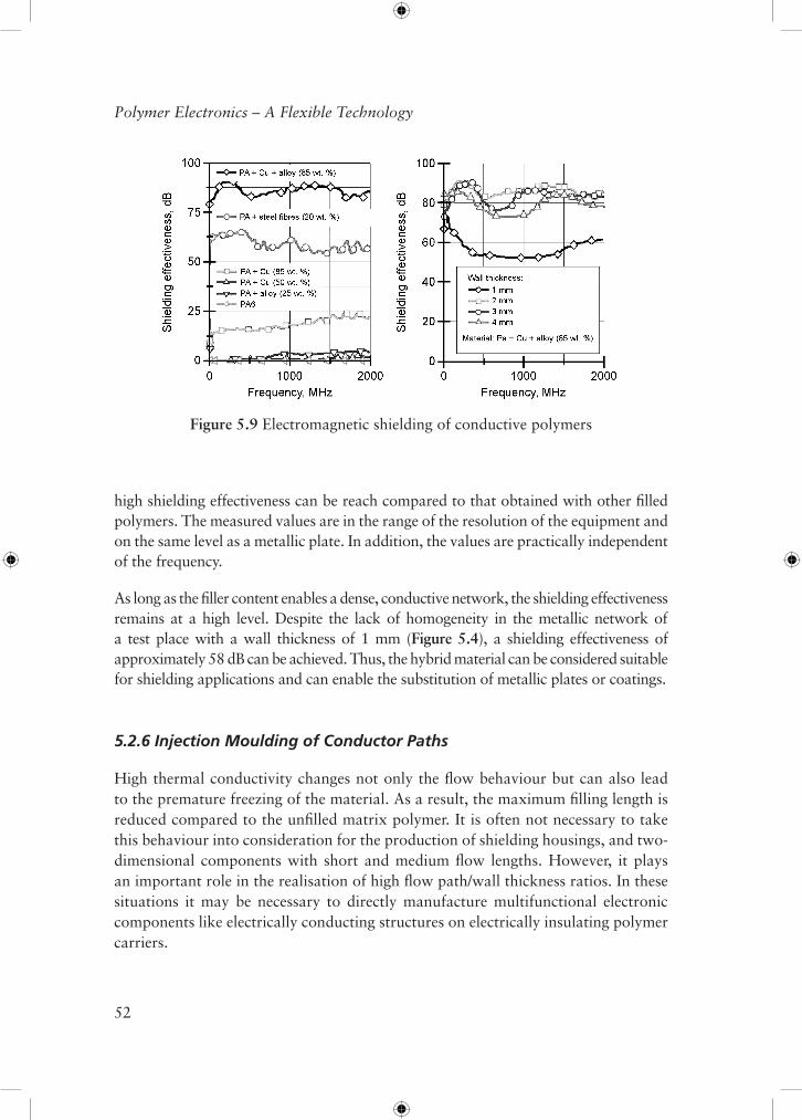
Plastics cannot alleviate the electromagnetic fields and waves due to their non-magnetic, insulating physical properties. A good shielding can only be achieved by conductive polymers, such as those filled with long steel fibres of 20 wt% [20, 21]. The combining of copper fibres with metal alloy is not only advantageous for electrical conductivity but also for electromagnetic shielding (Figure 5.9). To show this effect, the shielding of plates with a wall thickness of 2 mm was measured using transmission-line measuring equipment. Due to the pronounced metallic network of the hybrid material, a very
Figure 5.8 Material warming under current load
52
Polymer Electronics – A Flexible Technology
high shielding effectiveness can be reach compared to that obtained with other filled polymers. The measured values are in the range of the resolution of the equipment and on the same level as a metallic plate. In addition, the values are practically independent of the frequency.
As long as the filler content enables a dense, conductive network, the shielding effectiveness remains at a high level. Despite the lack of homogeneity in the metallic network of a test place with a wall thickness of 1 mm (Figure 5.4), a shielding effectiveness of approximately 58 dB can be achieved. Thus, the hybrid material can be considered suitable for shielding applications and can enable the substitution of metallic plates or coatings.
5.2.6 Injection Moulding of Conductor Paths
High thermal conductivity changes not only the flow behaviour but can also lead to the premature freezing of the material. As a result, the maximum filling length is reduced compared to the unfilled matrix polymer. It is often not necessary to take this behaviour into consideration for the production of shielding housings, and two-dimensional components with short and medium flow lengths. However, it plays an important role in the realisation of high flow path/wall thickness ratios. In these situations it may be necessary to directly manufacture multifunctional electronic components like electrically conducting structures on electrically insulating polymer carriers.
Figure 5.9 Electromagnetic shielding of conductive polymers

53
Highly Conductive Plastics – Custom-formulated Functional Materials for Injection Mouldable Electronic Applications
Altering the mould temperature can significantly influence the flow and freezing behaviour of polymer melts in the mould cavity [22]. In order to analyse the influence of the conductor cross-section on the flow length, conductor parts with different cross sections were injection moulded on unfilled polymer plates. In addition, the mould temperature was varied in a wide process window (Figure 5.10). It can be seen that a flow length of considerably more than 100 mm can be realised for a cross-section greater than 1 mm² with an oil-heated mould. Conductor cross-section sizes under 1 mm² only allow a flow length of less than 50 mm. Thus, the limit of the lowest conductor cross-section size is approximately 1 mm² due to the filler size used (length of copper fibres L = 0.3-0.8 mm). Furthermore, conductor paths with a greater height than width offer increased contact area with the mould, and therefore offer the preferred option. By means of an increased mould temperature of 180 °C the flow length can also be disproportionately improved.
Especially for the application of the material in conducting and/or shielding structures, the conductive elements and non-conductive carriers must be integrated in the same electronic system. In first preliminary tests the bond strength is tested using two-component tensile bars made of conducting compound and unfilled matrix polymer PA6. When applying the filled component to the unfilled polymer the stability only decreases marginally. The two components show good bond strength compared to conventional highly filled melts. Therefore, the compound is suitable for the employment in multi-component moulded assemblies.
Figure 5.10 Flow length in dependence on the conductor cross-section and the mould temperature

54
Polymer Electronics – A Flexible Technology
5.3 Conclusions and Outlook
The investigations presented show the high potential of the novel compounds for the use in moulded parts with high electrical conductivity. The material range stretches from carbon black compounds to metals and forms the transition between semiconductors and conductors.
The described thermoplastic/metal hybrid materials have a high potential for being employed in the production of complex electronic components with very high demands on the electrical conductivity.
Due to the injection moulding process moulded parts of highly filled material show a dependence of the distribution and direction of the filler material on the local position along the flow path and over the part’s thickness. Therefore, in the design of the moulded part it is important to consider not only global characteristic values but also the influence of the material composition, the process parameters as well as the geometries of gating system and cavity. This also makes it possible to systematically influence morphology and part properties during the compounding and injection moulding of the polymer/metal hybrid materials.
It can be briefly shown that the matrix polymer can be varied widely in order to adjust the compound properties for specific applications’ requirements. Thereby, a freezing of the polymer at the same time or later than the metal alloy and a low viscosity of the material can considerably improve the level and homogeneity of conductivity.
Moreover, the conductivities of the hybrid material are only slightly influenced by elevated temperatures. The conductivity is not considerably reduced until the softening temperature of approximately 200 °C is reached. As long as the cross-section is greater than 5 mm² at a comparatively low current load of approximately 10 A, the hybrid material does not heat up critically and can be used for conductor paths. Besides an outstanding electrical conductivity, an excellent shielding effectiveness is provided by the hybrid material due to the pronounced metallic network. This allows the material for being employed in the field of electromagnetic shielding applications.
High filling degrees and high thermal conductivity change the filling and freezing behavior of the material. This is particularly important for the production of conducting structures with high flow path/wall thickness ratios and may require an adjustment of the mould temperature control. First tests already point out that the minimum cross-section size is approximately 1 mm². Current research projects at the IKV are aimed at developing mould and process solutions for an optimised material processing of complex multi-component parts. Thereby, the use of inductive heating should be investigated at the IKV in order to further increase the flow distances.

55
Highly Conductive Plastics – Custom-formulated Functional Materials for Injection Mouldable Electronic Applications
Acknowledgements
The investigations set out in this report received financial support from the Federal Ministry of Economics and Technology (BMWi) by the Arbeitsgemeinschaft Industrieller Forschungsvereinigungen eV (AiF No. 15258 N), to whom we extend our thanks.
References
1. D. Drummer and R.Dörfler in Spritzgießen 2007, VDI-Verlag, Düsseldorf, Germany, 2007, p.141-157.
2. H.J. Mair and S. Roth, Elektrisch Leitende Kunststoffe, Carl Hanser Publishing, Munich, Germany, 1989.
3. A.K. Bledzki, L. Subocz and J. Subocz, Kunststoffe, 1992, 82, 3, 243.
4. B. Pfeiffer in the Proceedings of the OTTI Conference: Elektrisch Leitfaehige Kunststoffe, Regensburg, Germany, 2006.
5. J. Versieck in the Proceedings of the SPE Annual Technical Conference - ANTEC, Orlando, FL, USA, 2000, Paper No.290.
6. D.J. Jendritza, Auto & Elektronik, 2002, 3, 12.
7. K. Feldmann, 3D-MID Technologie, Carl Hanser Publishing, Munich, Germany, 2004.
8. S. Prollius and C. Hopmann, inventors; Foerderung Institut Kunststoff, assignee; DE 19,962,408, 2001.
9. E. Haberstroh, M. Hoelzel, M. Koch and E. Krampe, Kunststoffe, 2004, 94, 3, 106.
10. W. Michaeli and T. Pfefferkorn, Plastics, Rubber and Composites: Macromolecular Engineering, 2006, 35, 9, 380.
11. P. Thienel, Der Formfüllvorgang beim Spritzgießen von Thermoplasten, Rheinisch-Westfälische RWTH Aachen University, 1996. [PhD thesis]
12. G. Menges, W. Michaeli and P. Mohren, Anleitung zum Bau von Spritzgieß-Werkzeugen, Carl Hanser Verlag, Munich, Germany, 1999.

56
Polymer Electronics – A Flexible Technology
13. R. Schulze-Kadelbach, Fließverhalten Gefüllter Polymerschmelzen, Rheinisch-Westfälische Technische Hochschule Aachen, 1978. [PhD thesis]
14. P. Barth, Pulvermetallspritzgießen – Ein Beitrag zur Verarbeitung Ultrahoch-Fefüllter Kunststoffe, Rheinisch-Westfälische Technische Hochschule Aachen, 1988. [PhD thesis]
15. J.P. Greene and J.O. Wilkes, Polymer Engineering and Science, 1995, 35, 21, 1670.
16. G. Ruschau and R. Newnham, Journal of Composite Materials, 1992, 26, 18, 2727.
17. J.M. Knothe, Elektrische Eigenschaften von Spritzgegossenen Kunststofformteilen aus Leitfaehigen Compounds, RWTH Aachen University, Dissertation, 1996. [PhD thesis]
18. W-Z. Cai, S-T. Tu and J-M. Gong, Journal of Composite Materials, 2006, 40, 23, 2131.
19. D.M. Bigg, Advances in Polymer Technology, 1984, 4, 255.
20. U. Leute in the Proceedings of the OTTI Conference: Elektrisch Leitfaehige Kunststoffe, Regensburg, Germany, 2007.
21. S. Roth, Spritzgegossene Abschirmgehäuse aus Stahlfasergefüllten Thermoplasten – Materialeigenschaften, Verarbeitung und Gestaltung, Technical University Chemnitz, 2006. [PhD Thesis]
22. G. Wübken, Einfluss der Verarbeitungsbedingungen auf die innere Struktur thermoplastischer Spritzgussteile unter besonderer Berücksichtigung der Abkühlverhältnisse, RWTH Aachen University, 1978. [PhD thesis]


![Kyron MAX Sales E-mail Overview 9-22-14 [Read-Only]...2018/02/28 · Kyron MAX “XS” Series - Piper Plastics Inc. Confidential - KyronMAX XS Series XS-9260 XS-9160 Conductive Non-Conductive](https://static.fdocuments.us/doc/165x107/60d286df82df41664a083b3f/kyron-max-sales-e-mail-overview-9-22-14-read-only-20180228-kyron-max.jpg)