5-176 Saturated refrigerant-134a vapor at a saturation ... · PDF file5-176 Saturated...
34
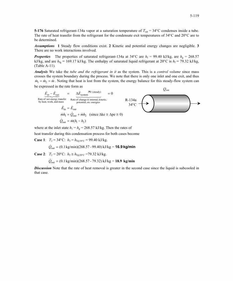
5-119 5-176 Saturated refrigerant-134a vapor at a saturation temperature of T sat = 34°C condenses inside a tube. The rate of heat transfer from the refrigerant for the condensate exit temperatures of 34°C and 20°C are to be determined. Assumptions 1 Steady flow conditions exist. 2 Kinetic and potential energy changes are negligible. 3 There are no work interactions involved. Properties The properties of saturated refrigerant-134a at 34°C are h f = 99.40 kJ/kg, are h g = 268.57 kJ/kg, and are h fg = 169.17 kJ/kg. The enthalpy of saturated liquid refrigerant at 20°C is h f = 79.32 kJ/kg, (Table A-11). Analysis We take the tube and the refrigerant in it as the system. This is a control volume since mass crosses the system boundary during the process. We note that there is only one inlet and one exit, and thus . Noting that heat is lost from the system, the energy balance for this steady-flow system can be expressed in the rate form as & & m m m 1 2 = = & Q out ) ( 0) pe ke (since 0 2 1 out 2 out 1 out in energies etc. potential, kinetic, internal, in change of Rate (steady) 0 system mass and work, heat, by nsfer energy tra net of Rate h h m Q h m Q h m E E E E E out in − = ≅ ∆ ≅ ∆ + = = = ∆ = − & & & & & & & 4 4 3 4 4 2 1 & 43 42 1 & & R-134a 34°C where at the inlet state h 1 = h g = 268.57 kJ/kg. Then the rates of heat transfer during this condensation process for both cases become Case 1: T 2 = 34°C: h 2 = h f@34°C = 99.40 kJ/kg. kg/min 16.9 = kJ/kg 99.40) - 8.57 kg/min)(26 1 . 0 ( out = Q & Case 2: T 2 = 20°C: h 2 ≅ h f@20°C =79.32 kJ/kg. kg/min 18.9 = kJ/kg 79.32) - 8.57 kg/min)(26 1 . 0 ( out = Q & Discussion Note that the rate of heat removal is greater in the second case since the liquid is subcooled in that case. PROPRIETARY MATERIAL . © 2006 The McGraw-Hill Companies, Inc. Limited distribution permitted only to teachers and
Transcript of 5-176 Saturated refrigerant-134a vapor at a saturation ... · PDF file5-176 Saturated...
5-119
5-176 Saturated refrigerant-134a vapor at a saturation temperature of Tsat = 34°C condenses inside a tube. The rate of heat transfer from the refrigerant for the condensate exit temperatures of 34°C and 20°C are to be determined. Assumptions 1 Steady flow conditions exist. 2 Kinetic and potential energy changes are negligible. 3 There are no work interactions involved. Properties The properties of saturated refrigerant-134a at 34°C are hf = 99.40 kJ/kg, are hg = 268.57 kJ/kg, and are hfg = 169.17 kJ/kg. The enthalpy of saturated liquid refrigerant at 20°C is hf = 79.32 kJ/kg, (Table A-11). Analysis We take the tube and the refrigerant in it as the system. This is a control volume since mass crosses the system boundary during the process. We note that there is only one inlet and one exit, and thus
. Noting that heat is lost from the system, the energy balance for this steady-flow system can be expressed in the rate form as & &m m m1 2= = &
Qout
)(
0)peke (since
0
21out
2out1
outin
energies etc. potential, kinetic, internal,in change of Rate
(steady) 0system
mass and work,heat,by nsferenergy tranet of Rate
hhmQ
hmQhm
EE
EEE outin
−=
≅∆≅∆+=
=
=∆=−
&&
&&&
&&
44 344 21&
43421&&
R-134a34°C
where at the inlet state h1 = hg = 268.57 kJ/kg. Then the rates of heat transfer during this condensation process for both cases become Case 1: T2 = 34°C: h2 = hf@34°C = 99.40 kJ/kg.
kg/min 16.9=kJ/kg 99.40)-8.57kg/min)(26 1.0(out =Q&
Case 2: T2 = 20°C: h2 ≅ hf@20°C =79.32 kJ/kg.
kg/min 18.9=kJ/kg 79.32)-8.57kg/min)(26 1.0(out =Q&
Discussion Note that the rate of heat removal is greater in the second case since the liquid is subcooled in that case.
PROPRIETARY MATERIAL. © 2006 The McGraw-Hill Companies, Inc. Limited distribution permitted only to teachers and educators for course preparation. If you are a student using this Manual, you are using it without permission.

5-120
5-177E A winterizing project is to reduce the infiltration rate of a house from 2.2 ACH to 1.1 ACH. The resulting cost savings are to be determined. Assumptions 1 The house is maintained at 72°F at all times. 2 The latent heat load during the heating season is negligible. 3 The infiltrating air is heated to 72°F before it exfiltrates. 4 Air is an ideal gas with constant specific heats at room temperature. 5 The changes in kinetic and potential energies are negligible. 6 Steady flow conditions exist. Properties The gas constant of air is 0.3704 psia.ft3/lbm⋅R (Table A-1E). The specific heat of air at room temperature is 0.24 Btu/lbm⋅°F (Table A-2E). Analysis The density of air at the outdoor conditions is
33
lbm/ft 0734.0R) 6.5/lbm.R)(49psia.ft 3704.0(
psia 5.13===
o
oo RT
Pρ
The volume of the house is 32
building ft 000,27ft) )(9ft 3000(ht)area)(HeigFloor ( ===V
We can view infiltration as a steady stream of air that is heated as it flows in an imaginary duct passing through the house. The energy balance for this imaginary steady-flow system can be expressed in the rate form as
Cold air 36.5°F
Warm air
72°F
)()(
0)peke (since
0
1212in
21in
outin
energies etc. potential, kinetic, internal,in change of Rate
(steady) 0system
mass and work,heat,by nsferenergy tranet of Rate
TTcTTcmQ
hmhmQ
EE
EEE
pp
outin
−=−=
≅∆≅∆=+
=
=∆=−
V&&&
&&&
&&
44 344 21&
43421&&
ρ
Warm air 72°F
The reduction in the infiltration rate is 2.2 – 1.1 = 1.1 ACH. The reduction in the sensible infiltration heat load corresponding to it is
therm/h0.18573=Btu/h 18,573=F36.5)-)(72ft 27,000F)(1.1/h)(Btu/lbm. )(0.24lbm/ft 0734.0(
))()((33
buildingsavedsaved on,infiltrati
°°=
−= oipo TTACHcQ Vρ&
since 1 therm = 100,000 Btu. The number of hours during a six month period is 6×30×24 = 4320 h. Noting that the furnace efficiency is 0.65 and the unit cost of natural gas is $1.24/therm, the energy and money saved during the 6-month period are
ar therms/ye1234=65h/year)/0. 4320 therm/h)(18573.0(
ciencyyear)/Effiper hours of No.)((savingsEnergy saved on,infiltrati
=
= Q&
$1530/year=
therm)ar)($1.24/ therms/ye1234(energy) ofcost Unit )(savingsEnergy (savingsCost
==
Therefore, reducing the infiltration rate by one-half will reduce the heating costs of this homeowner by $1530 per year.
PROPRIETARY MATERIAL. © 2006 The McGraw-Hill Companies, Inc. Limited distribution permitted only to teachers and educators for course preparation. If you are a student using this Manual, you are using it without permission.

5-121
5-178 Outdoors air at -5°C and 90 kPa enters the building at a rate of 35 L/s while the indoors is maintained at 20°C. The rate of sensible heat loss from the building due to infiltration is to be determined. Assumptions 1 The house is maintained at 20°C at all times. 2 The latent heat load is negligible. 3 The infiltrating air is heated to 20°C before it exfiltrates. 4 Air is an ideal gas with constant specific heats at room temperature. 5 The changes in kinetic and potential energies are negligible. 6 Steady flow conditions exist. Properties The gas constant of air is R = 0.287 kPa.m3/kg⋅K. The specific heat of air at room temperature is cp = 1.005 kJ/kg⋅°C (Table A-2). Analysis The density of air at the outdoor conditions is
33 kg/m 17.1
K) 273/kg.K)(-5kPa.m 287.0(kPa 90
=+
==o
oo RT
Pρ
We can view infiltration as a steady stream of air that is heated as it flows in an imaginary duct passing through the building. The energy balance for this imaginary steady-flow system can be expressed in the rate form as
Cold air -5°C
90 kPa 35 L/s
Warm air
20°C
)(
0)peke (since
0
12in
21in
outin
energies etc. potential, kinetic, internal,in change of Rate
(steady) 0system
mass and work,heat,by nsferenergy tranet of Rate
outin
TTcmQ
hmhmQ
EE
EEE
p −=
≅∆≅∆=+
=
=∆=−
&&
&&&
&&
44 344 21&
43421&&
Warm air 20°C
Then the sensible infiltration heat load corresponding to an infiltration rate of 35 L/s becomes
kW 1.029=
C(-5)]-C)[20kJ/kg. /s)(1.005m )(0.035kg/m 17.1(
)(33
oninfiltrati
°°=
−= oipairo TTcQ V&& ρ
Therefore, sensible heat will be lost at a rate of 1.029 kJ/s due to infiltration.
PROPRIETARY MATERIAL. © 2006 The McGraw-Hill Companies, Inc. Limited distribution permitted only to teachers and educators for course preparation. If you are a student using this Manual, you are using it without permission.

5-122
5-179 The maximum flow rate of a standard shower head can be reduced from 13.3 to 10.5 L/min by switching to low-flow shower heads. The ratio of the hot-to-cold water flow rates and the amount of electricity saved by a family of four per year by replacing the standard shower heads by the low-flow ones are to be determined. Assumptions 1 This is a steady-flow process since there is no change with time at any point and thus
. 2 The kinetic and potential energies are negligible, ∆ ∆m ECV CV and = 0 = 0 ke pe≅ ≅ 0 . 3 Heat losses from the system are negligible and thus . 4 There are no work interactions involved. 5 .Showers operate at maximum flow conditions during the entire shower. 6 Each member of the household takes a 5-min shower every day. 7 Water is an incompressible substance with constant properties. 8 The efficiency of the electric water heater is 100%.
&Q ≅ 0
Properties The density and specific heat of water at room temperature are ρ = 1 kg/L and c = 4.18 kJ/kg.°C (Table A-3). Analysis (a) We take the mixing chamber as the system. This is a control volume since mass crosses the system boundary during the process. We note that there are two inlets and one exit. The mass and energy balances for this steady-flow system can be expressed in the rate form as follows: Mass balance:
0
321outin
(steady) 0systemoutin
mmmmm
mmm&&&&&
&&&
=+→=
=∆=−
Energy balance:
)0 0, ,0 (since =
0
332211
outin
energies etc. potential, kinetic, internal,in change of Rate
(steady) 0system
mass and work,heat,by nsferenergy tranet of Rate
outin
≅≅=≅+
=
=∆=−
pekeWQhmhmhm
EE
EEE
&&&&&
&&
44 344 21&
43421&&
Mixture 3
Hot water
2
Cold water
1
Combining the mass and energy balances and rearranging,
& & ( & & )& ( ) & ( )m h m h m m hm h h m h h
1 1 2 2 1 2 3
2 2 3 1 3 1
+ = +− = −
Then the ratio of the mass flow rates of the hot water to cold water becomes
2.08=°−°−
=−−
=−−
=−−
=C)4255(C)1542(
)()(
32
13
32
13
32
13
1
2
TTTT
TTcTTc
hhhh
mm&
&
(b) The low-flow heads will save water at a rate of
kg/year 20,440=L/year) 40kg/L)(20,4 (1==
L/year 20,440=days/yr) 65persons)(3 .day)(4min/person L/min](5 10.5)-[(13.3=
savedsaved
saved
V
V&&
&
ρm
Then the energy saved per year becomes
kJ) 3600 =kWh 1 (since =kJ/year 2,307,000=
C15)-C)(42kJ/kg. .18kg/year)(4 (20,440==savedEnergy saved
kWh 641
°°∆Tcm&
Therefore, switching to low-flow shower heads will save about 641 kWh of electricity per year.
PROPRIETARY MATERIAL. © 2006 The McGraw-Hill Companies, Inc. Limited distribution permitted only to teachers and educators for course preparation. If you are a student using this Manual, you are using it without permission.

5-123
5-180 EES Problem 5-179 is reconsidered. The effect of the inlet temperature of cold water on the energy saved by using the low-flow showerhead as the inlet temperature varies from 10°C to 20°C is to be investigated. The electric energy savings is to be plotted against the water inlet temperature. Analysis The problem is solved using EES, and the results are tabulated and plotted below. "Knowns:" C_P = 4.18 [kJ/kg-K ] density=1[kg/L] {T_1 = 15 [C]} T_2 = 55 [C] T_3 = 42 [C] V_dot_old = 13.3 [L/min] V_dot_new = 10.5 [L/min] m_dot_1=1[kg/s] "We can set m_dot_1 = 1 without loss of generality." "Analysis:" "(a) We take the mixing chamber as the system. This is a control volume since mass crosses the system boundary during the process. We note that there are two inlets and one exit. The mass and energy balances for this steady-flow system can be expressed in the rate form as follows:" "Mass balance:" m_dot_in - m_dot_out = DELTAm_dot_sys DELTAm_dot_sys=0 m_dot_in =m_dot_1 + m_dot_2 m_dot_out = m_dot_3 "The ratio of the mass flow rates of the hot water to cold water is obtained by setting m_dot_1=1[kg/s]. Then m_dot_2 represents the ratio of m_dot_2/m_dot_1" "Energy balance:" E_dot_in - E_dot_out = DELTAE_dot_sys DELTAE_dot_sys=0 E_dot_in = m_dot_1*h_1 + m_dot_2*h_2 E_dot_out = m_dot_3*h_3 h_1 = C_P*T_1 h_2 = C_P*T_2 h_3 = C_P*T_3 "(b) The low-flow heads will save water at a rate of " V_dot_saved = (V_dot_old - V_dot_new)"L/min"*(5"min/person-day")*(4"persons")*(365"days/year") "[L/year]" m_dot_saved=density*V_dot_saved "[kg/year]" "Then the energy saved per year becomes" E_dot_saved=m_dot_saved*C_P*(T_3 - T_1)"kJ/year"*convert(kJ,kWh) "[kWh/year]" "Therefore, switching to low-flow shower heads will save about 641 kWh of electricity per year. " "Ratio of hot-to-cold water flow rates:" m_ratio = m_dot_2/m_dot_1
PROPRIETARY MATERIAL. © 2006 The McGraw-Hill Companies, Inc. Limited distribution permitted only to teachers and educators for course preparation. If you are a student using this Manual, you are using it without permission.

5-124
Esaved [kWh/year] T1 [C]
759.5 10 712 12
664.5 14 617.1 16 569.6 18 522.1 20
10 12 14 16 18 20500
550
600
650
700
750
800
T1 [C]
Esa
ved
[kW
h/ye
ar]
PROPRIETARY MATERIAL. © 2006 The McGraw-Hill Companies, Inc. Limited distribution permitted only to teachers and educators for course preparation. If you are a student using this Manual, you are using it without permission.

5-125
5-181 A fan is powered by a 0.5 hp motor, and delivers air at a rate of 85 m3/min. The highest possible air velocity at the fan exit is to be determined. Assumptions 1 This is a steady-flow process since there is no change with time at any point and thus
. 2 The inlet velocity and the change in potential energy are negligible, . 3 There are no heat and work interactions other than the electrical power consumed
by the fan motor. 4 The efficiencies of the motor and the fan are 100% since best possible operation is assumed. 5 Air is an ideal gas with constant specific heats at room temperature.
∆ ∆m ECV CV and = 00 and 01 ≅∆≅ peV
= 0
&
Properties The density of air is given to be ρ = 1.18 kg/m3. The constant pressure specific heat of air at room temperature is cp = 1.005 kJ/kg.°C (Table A-2). Analysis We take the fan-motor assembly as the system. This is a control volume since mass crosses the system boundary during the process. We note that there is only one inlet and one exit, and thus
. & &m m m1 2= =
The velocity of air leaving the fan will be highest when all of the entire electrical energy drawn by the motor is converted to kinetic energy, and the friction between the air layers is zero. In this best possible case, no energy will be converted to thermal energy, and thus the temperature change of air will be zero,
Then the energy balance for this steady-flow system can be expressed in the rate form as T T2 1= .
0)pe and 0 (since /2)+(
0
12
221ine,
outin
energies etc. potential, kinetic, internal,in change of Rate
(steady) 0system
mass and work,heat,by nsferenergy tranet of Rate
outin
≅∆≅=+
=
=∆=−
VVhmhmW
EE
EEE
&&&
&&
44 344 21&
43421&&
0.5 hp 85 m3/min
Noting that the temperature and thus enthalpy remains constant, the relation above simplifies further to
/222, VmW ine && =
where
kg/s 1.67=kg/min 100.3=/min)m )(85kg/m 18.1( 33== V&& ρm
Solving for V2 and substituting gives
m/s 21.1=
==
W1s/m 1
hp 1 W7.745
kg/s 67.1hp) 5.0(22 22
,2 m
WV ine
&
&
Discussion In reality, the velocity will be less because of the inefficiencies of the motor and the fan.
PROPRIETARY MATERIAL. © 2006 The McGraw-Hill Companies, Inc. Limited distribution permitted only to teachers and educators for course preparation. If you are a student using this Manual, you are using it without permission.

5-126
5-182 The average air velocity in the circular duct of an air-conditioning system is not to exceed 10 m/s. If the fan converts 70 percent of the electrical energy into kinetic energy, the size of the fan motor needed and the diameter of the main duct are to be determined. Assumptions 1 This is a steady-flow process since there is no change with time at any point and thus
. 2 The inlet velocity is negligible, ∆ ∆m ECV CV and = 0 = 0 .01 ≅V 3 There are no heat and work interactions other than the electrical power consumed by the fan motor. 4 Air is an ideal gas with constant specific heats at room temperature. Properties The density of air is given to be ρ = 1.20 kg/m3. The constant pressure specific heat of air at room temperature is cp = 1.005 kJ/kg.°C (Table A-2). Analysis We take the fan-motor assembly as the system. This is a control volume since mass crosses the system boundary during the process. We note that there is only one inlet and one exit, and thus
. The change in the kinetic energy of air as it is accelerated from zero to 10 m/s at a rate of 180 m& &m m m1 2= = &
3/s is
kW 18.0s/m 1000
kJ/kg 12
0m/s) 10()kg/s 6.3(2
=EK
kg/s 3.6=kg/min 216=/min)m )(180kg/m 20.1(
22
221
22
33
=
−=
−∆
==
VVm
m
&&
&& Vρ
10 m/s 180 m3/min
It is stated that this represents 70% of the electrical energy consumed by the motor. Then the total electrical power consumed by the motor is determined to be
0 70 7
018. & & &&
..W KE W KE
motor motor kW0.7
= → = = =∆∆ 0.257 kW
The diameter of the main duct is
m 0.618=
==→==
s 60min 1
m/s) 10(min)/m 180(44 )4/(
32
πππ
VDDVVAV V&&
Therefore, the motor should have a rated power of at least 0.257 kW, and the diameter of the duct should be at least 61.8 cm 5-183 An evacuated bottle is surrounded by atmospheric air. A valve is opened, and air is allowed to fill the bottle. The amount of heat transfer through the wall of the bottle when thermal and mechanical equilibrium is established is to be determined. Assumptions 1 This is an unsteady process since the conditions within the device are changing during the process, but it can be analyzed as a uniform-flow process since the state of fluid at the inlet remains constant. 2 Air is an ideal gas. 3 Kinetic and potential energies are negligible. 4 There are no work interactions involved. 5 The direction of heat transfer is to the air in the bottle (will be verified). Analysis We take the bottle as the system. It is a control volume since mass crosses the boundary. Noting that the microscopic energies of flowing and nonflowing fluids are represented by enthalpy h and internal energy u, respectively, the mass and energy balances for this uniform-flow system can be expressed as Mass balance: )0 (since initialout2systemoutin ===→∆=− mmmmmmm i
Energy balance:
)0pekeinitial2in
Change
system
mass and work,heat,by nsferenergy traNet
outin
≅≅==+
∆=−
umhmQ
EEE
ii
4342143421
(since out2
energies etc. potential,kinetic, internal,in
=≅ EEW
)( 22 ipTcTcm −= v
VV
000
00 PRT
RTPRT −=−=
P0 T0
V Evacuated
Combining the two balances: Q )( 22in ihum −=
But Ti = T2 = T0 and cp - cv = R. Substituting,
( )v 202in mTccm p −=−=Q
Therefore, Qout = P0V (Heat is lost from the tank)
PROPRIETARY MATERIAL. © 2006 The McGraw-Hill Companies, Inc. Limited distribution permitted only to teachers and educators for course preparation. If you are a student using this Manual, you are using it without permission.

5-127
5-184 An adiabatic air compressor is powered by a direct-coupled steam turbine, which is also driving a generator. The net power delivered to the generator is to be determined. Assumptions 1 This is a steady-flow process since there is no change with time. 2 Kinetic and potential energy changes are negligible. 3 The devices are adiabatic and thus heat transfer is negligible. 4 Air is an ideal gas with variable specific heats. Properties From the steam tables (Tables A-4 through 6)
and
( )( ) kJ/kg 2392.52392.10.92191.8192.0kPa 10
kJ/kg 3343.6C500MPa 12.5
444
4
33
3
=+=+=
==
=
°==
fgf hxhhxP
hTP
From the air table (Table A-17),
kJ/kg 628.07K 620
kJ/kg 295.17K 295
22
11
=→=
=→=
hT
hT
Steam turbine
Air comp
12.5 MPa 500°C 1 MPa
620 K
98 kPa 295 K
Analysis There is only one inlet and one exit for either device, and thus . We take either the turbine or the compressor as the system, which is a control volume since mass crosses the boundary. The energy balance for either steady-flow system can be expressed in the rate form as
outin mmm &&& ==
outin
energies etc. potential, kinetic, internal,in change of Rate
(steady) 0system
mass and work,heat,by nsferenergy tranet of Rate
outin 0
EE
EEE
&&
44 344 21&
43421&&
=
=∆=− 10 kPa
For the turbine and the compressor it becomes
Compressor: W m & & & & & (h m h W m hcomp, in air air comp, in air ) + = → = −1 2 2 h1
3 4Turbine: & & & & & (m h W m h W m h hsteam turb, out steam turb, out steam ) 3 4= + → = −
Substituting,
( )( )( )( ) kW 23,777kJ/kg 2392.53343.6kg/s 25
kW 3329kJ/kg 295.17628.07kg/s 10
outturb,
incomp,
=−=
=−=
W
W&
&
Therefore,
kW 20,448=−=−= 3329777,23incomp,outturb,outnet, WWW &&&
PROPRIETARY MATERIAL. © 2006 The McGraw-Hill Companies, Inc. Limited distribution permitted only to teachers and educators for course preparation. If you are a student using this Manual, you are using it without permission.
5-128
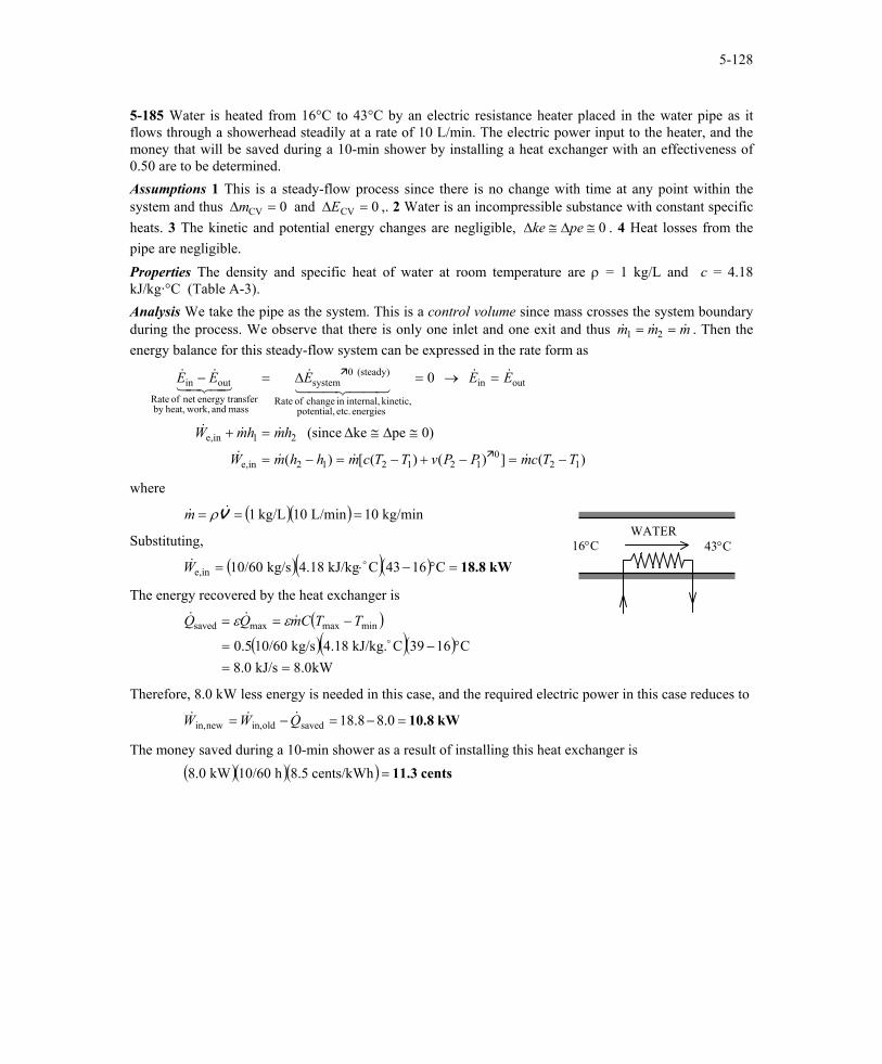
5-185 Water is heated from 16°C to 43°C by an electric resistance heater placed in the water pipe as it flows through a showerhead steadily at a rate of 10 L/min. The electric power input to the heater, and the money that will be saved during a 10-min shower by installing a heat exchanger with an effectiveness of 0.50 are to be determined. Assumptions 1 This is a steady-flow process since there is no change with time at any point within the system and thus ∆ ∆m ECV CV and = =0 0 ,. 2 Water is an incompressible substance with constant specific heats. 3 The kinetic and potential energy changes are negligible, ∆ ∆ke pe≅ ≅ 0 . 4 Heat losses from the pipe are negligible. Properties The density and specific heat of water at room temperature are ρ = 1 kg/L and c = 4.18 kJ/kg·°C (Table A-3). Analysis We take the pipe as the system. This is a control volume since mass crosses the system boundary during the process. We observe that there is only one inlet and one exit and thus m m . Then the energy balance for this steady-flow system can be expressed in the rate form as
& & m1 2= = &
)(])()([)(
0)peke (since
0
120
121212ine,
21ine,
outin
energies etc. potential, kinetic, internal,in change of Rate
(steady) 0system
mass and work,heat,by nsferenergy tranet of Rate
outin
TTcmPPvTTcmhhmW
hmhmW
EEEEE
−=−+−=−=
≅∆≅∆=+
=→=∆=−
&&&&
&&&
&&44 344 21
&43421&&
where
( )( ) kg/min 10L/min 10kg/L 1 === V&& ρmWATER
43°C16°CSubstituting,
( )( )( ) kW18.8 C1643CkJ/kg 4.18kg/s 10/60ine, =°−⋅= o&W
The energy recovered by the heat exchanger is
( )( )( )( )
kW8.0kJ/s 8.0C1639CkJ/kg. 4.18kg/s 10/600.5
minmaxmaxsaved
==°−=
−==o
&&& TTCmQQ εε
Therefore, 8.0 kW less energy is needed in this case, and the required electric power in this case reduces to
kW10.8 0.88.18savedoldin,newin, =−=−= QWW &&&
The money saved during a 10-min shower as a result of installing this heat exchanger is ( )( )( ) cents11.3 cents/kWh 8.5h 10/60kW 8.0 =
PROPRIETARY MATERIAL. © 2006 The McGraw-Hill Companies, Inc. Limited distribution permitted only to teachers and educators for course preparation. If you are a student using this Manual, you are using it without permission.
5-129
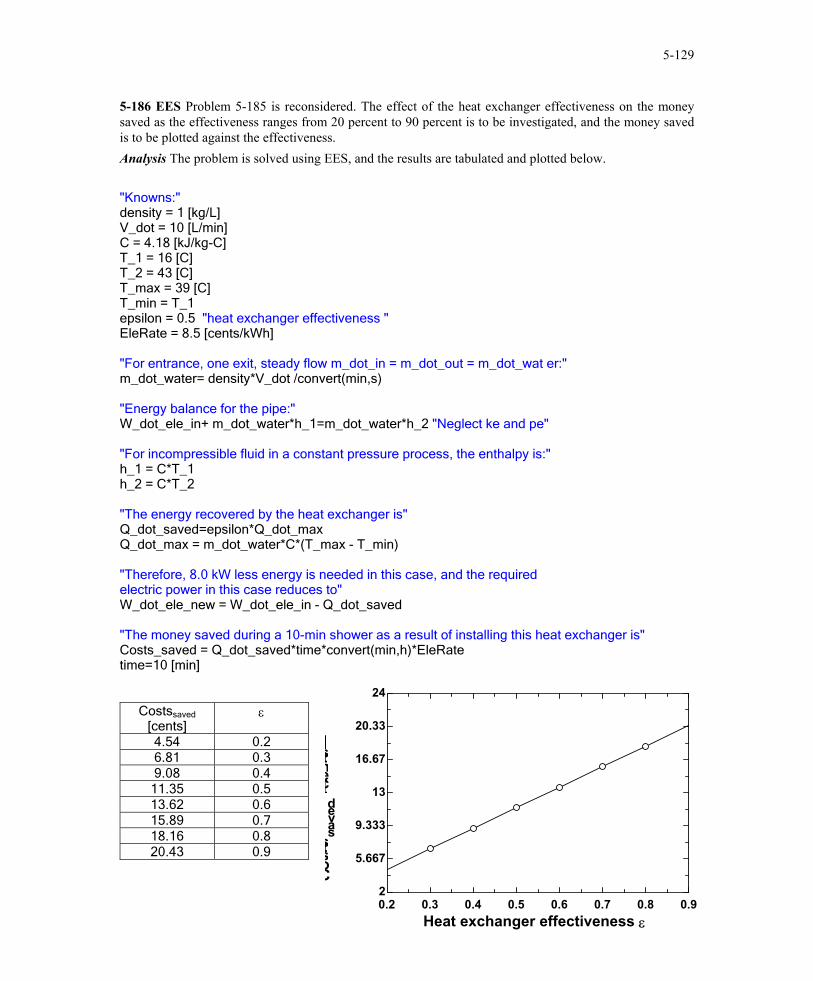
5-186 EES Problem 5-185 is reconsidered. The effect of the heat exchanger effectiveness on the money saved as the effectiveness ranges from 20 percent to 90 percent is to be investigated, and the money saved is to be plotted against the effectiveness. Analysis The problem is solved using EES, and the results are tabulated and plotted below. "Knowns:" density = 1 [kg/L] V_dot = 10 [L/min] C = 4.18 [kJ/kg-C] T_1 = 16 [C] T_2 = 43 [C] T_max = 39 [C] T_min = T_1 epsilon = 0.5 "heat exchanger effectiveness " EleRate = 8.5 [cents/kWh] "For entrance, one exit, steady flow m_dot_in = m_dot_out = m_dot_wat er:" m_dot_water= density*V_dot /convert(min,s) "Energy balance for the pipe:" W_dot_ele_in+ m_dot_water*h_1=m_dot_water*h_2 "Neglect ke and pe" "For incompressible fluid in a constant pressure process, the enthalpy is:" h_1 = C*T_1 h_2 = C*T_2 "The energy recovered by the heat exchanger is" Q_dot_saved=epsilon*Q_dot_max Q_dot_max = m_dot_water*C*(T_max - T_min) "Therefore, 8.0 kW less energy is needed in this case, and the required electric power in this case reduces to" W_dot_ele_new = W_dot_ele_in - Q_dot_saved "The money saved during a 10-min shower as a result of installing this heat exchanger is" Costs_saved = Q_dot_saved*time*convert(min,h)*EleRate time=10 [min]
Costssaved [cents]
ε
4.54 0.2 6.81 0.3 9.08 0.4
11.35 0.5 13.62 0.6 15.89 0.7 18.16 0.8 20.43 0.9
0.2 0.3 0.4 0.5 0.6 0.7 0.8 0.92
5.667
9.333
13
16.67
20.33
24
Heat exchanger effectiveness ε
Costssaved
[cents]
PROPRIETARY MATERIAL. © 2006 The McGraw-Hill Companies, Inc. Limited distribution permitted only to teachers and educators for course preparation. If you are a student using this Manual, you are using it without permission.

5-130
5-187 [Also solved by EES on enclosed CD] Steam expands in a turbine steadily. The mass flow rate of the steam, the exit velocity, and the power output are to be determined. Assumptions 1 This is a steady-flow process since there is no change with time. 2 Potential energy changes are negligible.
1 30 kJ/kg
Properties From the steam tables (Tables A-4 through 6)
and
( )( )( )( ) kJ/kg 2500.22345.50.95271.96
/kgm 5.89330.00102-6.20340.950.0010295.0
kPa 25
kJ/kg 3502.0/kgm 0.035655
C055MPa 10
22
322
2
2
1
31
1
1
=+=+==+=+=
==
==
°==
fgf
fgf
hxhhx
xP
hTP
vvv
v H2O
2
Analysis (a) The mass flow rate of the steam is
( )( ) kg/s 25.24=== 2311
1m 0.015m/s 60
/kgm 0.03565511 AVm
v&
(b) There is only one inlet and one exit, and thus & &m m m1 2 &= = . Then the exit velocity is determined from
m/s 1063===→=2
3
2
2222
2 m 0.14)/kgm 5.8933)(kg/s 25.24(1
Am
VAVmv
v
&&
(c) We take the turbine as the system, which is a control volume since mass crosses the boundary. The energy balance for this steady-flow system can be expressed in the rate form as
outin
energies etc. potential, kinetic, internal,in change of Rate
(steady) 0system
mass and work,heat,by nsferenergy tranet of Rate
outin 0
EE
EEE
&&
44 344 21&
43421&&
=
=∆=−
−+−−−=
≅∆++=+
2
0)pe (since /2)+()2/(2
12
212outout
222outout
211
VVhhmQW
VhmQWVhm
&&&
&&&&
Then the power output of the turbine is determined by substituting to be
( ) ( ) ( ) ( )
kW 10,330=
−+−−×−= 22
22
out /sm 1000kJ/kg 1
2m/s 60m/s 10633502.02500.2kg/s 25.24kJ/s 3025.24W&
PROPRIETARY MATERIAL. © 2006 The McGraw-Hill Companies, Inc. Limited distribution permitted only to teachers and educators for course preparation. If you are a student using this Manual, you are using it without permission.
5-131
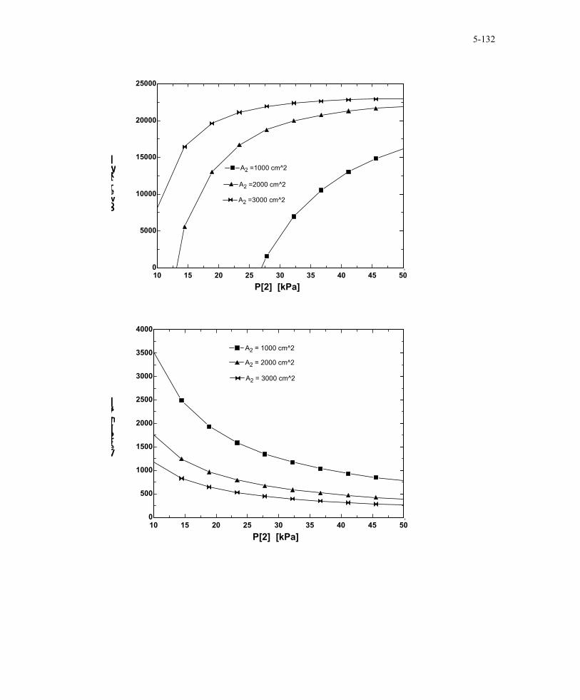
5-188 EES Problem 5-187 is reconsidered. The effects of turbine exit area and turbine exit pressure on the exit velocity and power output of the turbine as the exit pressure varies from 10 kPa to 50 kPa (with the same quality), and the exit area to varies from 1000 cm2 to 3000 cm2 is to be investigated. The exit velocity and the power output are to be plotted against the exit pressure for the exit areas of 1000, 2000, and 3000 cm2. Analysis The problem is solved using EES, and the results are tabulated and plotted below. Fluid$='Steam_IAPWS' A[1]=150 [cm^2] T[1]=550 [C] P[1]=10000 [kPa] Vel[1]= 60 [m/s] A[2]=1400 [cm^2] P[2]=25 [kPa] q_out = 30 [kJ/kg] m_dot = A[1]*Vel[1]/v[1]*convert(cm^2,m^2) v[1]=volume(Fluid$, T=T[1], P=P[1]) "specific volume of steam at state 1" Vel[2]=m_dot*v[2]/(A[2]*convert(cm^2,m^2)) v[2]=volume(Fluid$, x=0.95, P=P[2]) "specific volume of steam at state 2" T[2]=temperature(Fluid$, P=P[2], v=v[2]) "[C]" "not required, but good to know" "[conservation of Energy for steady-flow:" "Ein_dot - Eout_dot = DeltaE_dot" "For steady-flow, DeltaE_dot = 0" DELTAE_dot=0 "[kW]" "For the turbine as the control volume, neglecting the PE of each flow steam:" E_dot_in=E_dot_out h[1]=enthalpy(Fluid$,T=T[1], P=P[1]) E_dot_in=m_dot*(h[1]+ Vel[1]^2/2*Convert(m^2/s^2, kJ/kg)) h[2]=enthalpy(Fluid$,x=0.95, P=P[2]) E_dot_out=m_dot*(h[2]+ Vel[2]^2/2*Convert(m^2/s^2, kJ/kg))+ m_dot *q_out+ W_dot_out Power=W_dot_out Q_dot_out=m_dot*q_out
Power [kW] P2 [kPa] Vel2 [m/s] -54208 10 2513 -14781 14.44 1778 750.2 18.89 1382 8428 23.33 1134
12770 27.78 962.6 15452 32.22 837.6 17217 36.67 742.1 18432 41.11 666.7 19299 45.56 605.6 19935 50 555
PROPRIETARY MATERIAL. © 2006 The McGraw-Hill Companies, Inc. Limited distribution permitted only to teachers and educators for course preparation. If you are a student using this Manual, you are using it without permission.
5-132
10 15 20 25 30 35 40 45 500
5000
10000
15000
20000
25000
P[2] [kPa]
Power[kW]
A2 =1000 cm^2A2 =1000 cm^2
A2 =2000 cm^2A2 =2000 cm^2
A2 =3000 cm^2A2 =3000 cm^2
10 15 20 25 30 35 40 45 500
500
1000
1500
2000
2500
3000
3500
4000
P[2] [kPa]
Vel[2][m/s]
A2 = 1000 cm^2A2 = 1000 cm^2
A2 = 2000 cm^2A2 = 2000 cm^2
A2 = 3000 cm^2A2 = 3000 cm^2
PROPRIETARY MATERIAL. © 2006 The McGraw-Hill Companies, Inc. Limited distribution permitted only to teachers and educators for course preparation. If you are a student using this Manual, you are using it without permission.
5-133
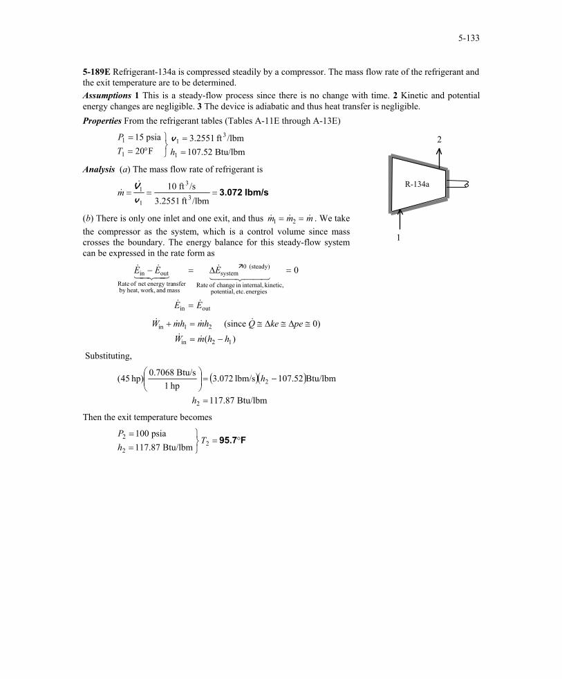
5-189E Refrigerant-134a is compressed steadily by a compressor. The mass flow rate of the refrigerant and the exit temperature are to be determined. Assumptions 1 This is a steady-flow process since there is no change with time. 2 Kinetic and potential energy changes are negligible. 3 The device is adiabatic and thus heat transfer is negligible. Properties From the refrigerant tables (Tables A-11E through A-13E)
Btu/lbm 107.52
/lbmft 3.2551F20psia 15
1
31
1
1
==
°==
hTP v 2
R-134a
Analysis (a) The mass flow rate of refrigerant is
lbm/s 3.072===/lbmft 3.2551
/sft 103
3
1
1
v
V&&m
(b) There is only one inlet and one exit, and thus & &m m m1 2 &= = . We take the compressor as the system, which is a control volume since mass crosses the boundary. The energy balance for this steady-flow system can be expressed in the rate form as
1
outin
energies etc. potential, kinetic, internal,in change of Rate
(steady) 0system
mass and work,heat,by nsferenergy tranet of Rate
outin 0
EE
EEE
&&
44 344 21&
43421&&
=
=∆=−
& & & &
& & ( )
W mh mh Q ke pe
W m h hin
in
(since 0)+ = ≅ ≅ ≅
= −1 2
2 1
∆ ∆
Substituting,
( )( )
Btu/lbm 117.87
Btu/lbm107.52lbm/s 3.072hp 1
Btu/s 0.7068hp) 45(
2
2
=
−=
h
h
Then the exit temperature becomes
F95.7°=
==
22
2
Btu/lbm 117.87psia 100
ThP
PROPRIETARY MATERIAL. © 2006 The McGraw-Hill Companies, Inc. Limited distribution permitted only to teachers and educators for course preparation. If you are a student using this Manual, you are using it without permission.

5-134
5-190 Air is preheated by the exhaust gases of a gas turbine in a regenerator. For a specified heat transfer rate, the exit temperature of air and the mass flow rate of exhaust gases are to be determined. Assumptions 1 This is a steady-flow process since there is no change with time. 2 Kinetic and potential energy changes are negligible. 3 There are no work interactions. 4 Heat loss from the regenerator to the surroundings is negligible and thus heat transfer from the hot fluid is equal to the heat transfer to the cold fluid. 5 Exhaust gases can be treated as air. 6 Air is an ideal gas with variable specific heats. Properties The gas constant of air is 0.287 kPa.m3/kg.K (Table A-1). The enthalpies of air are (Table A-17)
kJ/kg 02.607 K 600kJ/kg 95.821 K 800kJ/kg 74.555 K 550
44
33
11
=→==→==→=
hThThT
AIR
2
1
4
3
Exhaust Gases Analysis (a) We take the air side of the heat exchanger as the
system, which is a control volume since mass crosses the boundary. There is only one inlet and one exit, and thus
. The energy balance for this steady-flow system can be expressed in the rate form as & &m m m1 2= = &
)(
0)peke (since
0
12airin
2air1airin
outin
energies etc. potential, kinetic, internal,in change of Rate
(steady) 0system
mass and work,heat,by nsferenergy tranet of Rate
outin
hhmQ
WhmhmQ
EE
EEE
−=
≅∆≅∆==+
=
=∆=−
&&
&&&&
&&
44 344 21&
43421&&
Substituting, 3200 ( )( ) kJ/kg 554.71kg/s 800/60kJ/s 2 →−= h h2 = 794.71 kJ/kg
Then from Table A-17 we read T2 = 775.1 K (b) Treating the exhaust gases as an ideal gas, the mass flow rate of the exhaust gases is determined from the steady-flow energy relation applied only to the exhaust gases,
)(
0)peke (since
43exhaustout
4exhaustout3exhaust
outin
hhmQ
WhmQhm
EE
−=
≅∆≅∆=+=
=
&&
&&&&
&&
( ) kJ/kg 607.02-821.95kJ/s 3200 exhaustm&=
It yields kg/s 14.9=exhaustm&
PROPRIETARY MATERIAL. © 2006 The McGraw-Hill Companies, Inc. Limited distribution permitted only to teachers and educators for course preparation. If you are a student using this Manual, you are using it without permission.

5-135
5-191 Water is to be heated steadily from 20°C to 55°C by an electrical resistor inside an insulated pipe. The power rating of the resistance heater and the average velocity of the water are to be determined. Assumptions 1 This is a steady-flow process since there is no change with time at any point within the system and thus ∆ ∆m ECV CV and = =0 0 . 2 Water is an incompressible substance with constant specific heats. 3 The kinetic and potential energy changes are negligible, ∆ ∆ke pe≅ ≅ 0 . 4 The pipe is insulated and thus the heat losses are negligible. Properties The density and specific heat of water at room temperature are ρ = 1000 kg/m3 and c = 4.18 kJ/kg·°C (Table A-3). Analysis (a) We take the pipe as the system. This is a control volume since mass crosses the system boundary during the process. Also, there is only one inlet and one exit and thus m m . The energy balance for this steady-flow system can be expressed in the rate form as
& & m1 2= = &
( )120
1212ine,
out21ine,
outin
energies etc. potential, kinetic, internal,in change of Rate
(steady) 0system
mass and work,heat,by nsferenergy tranet of Rate
outin
])([)(
0)peke (since
0
TTcmPTTcmhhmW
QhmhmW
EE
EEE
−=∆+−=−=
≅∆≅∆≅=+
=
=∆=−
&&&&
&&&&
&&
44 344 21&
43421&&
v
WATER 30 L/min D = 5 cm
We ·
The mass flow rate of water through the pipe is
kg/min 30)/minm 0.030)(kg/m 1000( 331 === V&& ρm
Therefore,
kW73.2 C)2055)(CkJ/kg 4.18)(kg/s 30/60()( 12ine, =−⋅=−= oo&& TTcmW
(b) The average velocity of water through the pipe is determined from
m/min15.3 )m 0.025(π
/minm 0.0302
3
21
11 ====
rAV
πVV &&
PROPRIETARY MATERIAL. © 2006 The McGraw-Hill Companies, Inc. Limited distribution permitted only to teachers and educators for course preparation. If you are a student using this Manual, you are using it without permission.
5-136
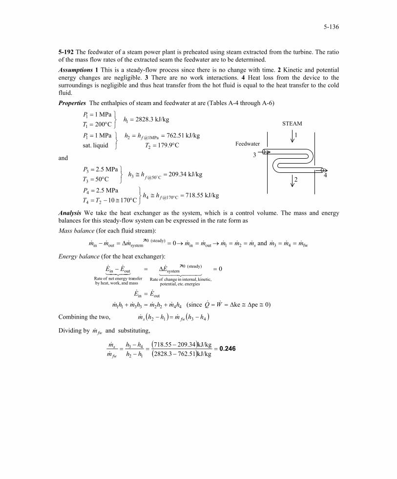
5-192 The feedwater of a steam power plant is preheated using steam extracted from the turbine. The ratio of the mass flow rates of the extracted seam the feedwater are to be determined. Assumptions 1 This is a steady-flow process since there is no change with time. 2 Kinetic and potential energy changes are negligible. 3 There are no work interactions. 4 Heat loss from the device to the surroundings is negligible and thus heat transfer from the hot fluid is equal to the heat transfer to the cold fluid. Properties The enthalpies of steam and feedwater at are (Tables A-4 through A-6)
C179.9kJ/kg 762.51
liquid sat.MPa 1
kJ/kg 2828.3C200
MPa 1
2
MPa1@21
11
1
°===
=
=
°==
ThhP
hTP
f
STEAM
2
1
4
Feedwater
3and
kJ/kg 718.55C17010
MPa 2.5
kJ/kg 209.34C50MPa 2.5
C170@424
4
C50@33
3
=≅
°≅−==
=≅
°==
°f
f
hhTT
P
hhTP
o
Analysis We take the heat exchanger as the system, which is a control volume. The mass and energy balances for this steady-flow system can be expressed in the rate form as Mass balance (for each fluid stream):
fw4321outin(steady) 0
systemoutin and 0 mmmmmmmmmmm s &&&&&&&&&&& ====→=→=∆=−
Energy balance (for the heat exchanger):
0)peke (since
0
44223311
outin
energies etc. potential, kinetic, internal,in change of Rate
(steady) 0system
mass and work,heat,by nsferenergy tranet of Rate
outin
≅∆≅∆==+=+
=
=∆=−
WQhmhmhmhm
EE
EEE
&&&&&&
&&
44 344 21&
43421&&
Combining the two, ( ) ( )4312 hhmhhm fws −=− &&
Dividing by and substituting, &mfw
( )( ) 0.246=
−−
=−−
=kJ/kg762.512828.3kJ/kg209.34718.55
12
43
hhhh
mm
fw
s&
&
PROPRIETARY MATERIAL. © 2006 The McGraw-Hill Companies, Inc. Limited distribution permitted only to teachers and educators for course preparation. If you are a student using this Manual, you are using it without permission.

5-137
5-193 A building is to be heated by a 30-kW electric resistance heater placed in a duct inside. The time it takes to raise the interior temperature from 14°C to 24°C, and the average mass flow rate of air as it passes through the heater in the duct are to be determined. Assumptions 1 Steady operating conditions exist. 2 Air is an ideal gas with constant specific heats at room temperature. 3 Kinetic and potential energy changes are negligible. 4 The heating duct is adiabatic, and thus heat transfer through it is negligible. 5 No air leaks in and out of the building. Properties The gas constant of air is 0.287 kPa.m3/kg.K (Table A-1). The specific heats of air at room temperature are cp = 1.005 and cv = 0.718 kJ/kg·K (Table A-2). Analysis (a) The total mass of air in the building is
( )( )( )( )
kg 461.3K 287K/kgmkPa 0.287
m 400kPa 953
3
1
11 =⋅⋅
==RTPm V .
We first take the entire building as our system, which is a closed system since no mass leaks in or out. The time required to raise the air temperature to 24°C is determined by applying the energy balance to this constant volume closed system:
( ) ( )12avg,outinfan,ine,
outinfan,ine,
energies etc. potential, kinetic, internal,in Change
system
mass and work,heat,by nsferenergy traNet
outin
0)=PE=KE (since
TTmcQWWt
UQWW
EEE
−=−+∆
∆∆∆=−+
∆=−
v&&&
4342143421
T1
T2 = T1 + 5°C
14°C → 24°C
V = 400 m3 P = 95 kPa
450 kJ/min
250 W
We
Solving for ∆t gives
( )s 146=
−+−⋅
=−+
−=∆
)kJ/s 450/60(kJ/s) 25.0()kJ/s 30(C)1424)(CkJ/kg 0.718)(kg 461.3(
outinfan,ine,
12avg,oo
&& QWWTTmc
t v
(b) We now take the heating duct as the system, which is a control volume since mass crosses the boundary. There is only one inlet and one exit, and thus & &m m m1 2 &= = . The energy balance for this adiabatic steady-flow system can be expressed in the rate form as
)()(
0)peke (since
0
1212infan,ine,
21infan,ine,
outin
energies etc. potential, kinetic, internal,in change of Rate
(steady) 0system
mass and work,heat,by nsferenergy tranet of Rate
outin
TTcmhhmWW
QhmhmWW
EE
EEE
p −=−=+
≅∆≅∆==++
=
=∆=−
&&&&
&&&&&
&&
44 344 21&
43421&&
Thus,
kg/s6.02 )C5)(CkJ/kg 1.005(
kJ/s 0.25)(30infan,ine, =⋅
+=
∆
+=
oo
&&&
TcWW
mp
PROPRIETARY MATERIAL. © 2006 The McGraw-Hill Companies, Inc. Limited distribution permitted only to teachers and educators for course preparation. If you are a student using this Manual, you are using it without permission.

5-138
5-194 [Also solved by EES on enclosed CD] An insulated cylinder equipped with an external spring initially contains air. The tank is connected to a supply line, and air is allowed to enter the cylinder until its volume doubles. The mass of the air that entered and the final temperature in the cylinder are to be determined. Assumptions 1 This is an unsteady process since the conditions within the device are changing during the process, but it can be analyzed as a uniform-flow process since the state of fluid at the inlet remains constant. 2 The expansion process is quasi-equilibrium. 3 Kinetic and potential energies are negligible. 4 The spring is a linear spring. 5 The device is insulated and thus heat transfer is negligible. 6 Air is an ideal gas with constant specific heats. Properties The gas constant of air is R = 0.287 kJ/kg·K (Table A-1). The specific heats of air at room temperature are cv = 0.718 and cp = 1.005 kJ/kg·K (Table A-2a). Also, u = cvT and h = cpT.
Fspring
Pi = 0.8 MPa Ti = 22°C
P = 200 kPa T1 = 22°C
V1 = 0.2 m3
Air
Analysis We take the cylinder as the system, which is a control volume since mass crosses the boundary. Noting that the microscopic energies of flowing and nonflowing fluids are represented by enthalpy h and internal energy u, respectively, the mass and energy balances for this uniform-flow system can be expressed as Mass balance: 12systemoutin mmmmmm i −=→∆=−
Energy balance:
)0peke (since 1122outb,
energies etc. potential, kinetic, internal,in Change
system
mass and work,heat,by nsferenergy traNet
outin
≅≅≅−+=
∆=−
QumumWhm
EEE
ii
4342143421
Combining the two relations, ( ) 1122,12 umumWhmm outbi −+=−
or, 1122,12 )( TcmTcmWTcmm outbip vv −+=−
The initial and the final masses in the tank are
( )( )( )( )
( )( )( ) 22
3
3
2
222
3
3
1
111
836.2K/kgmkPa 0.287
m 0.4kPa 600
kg 0.472K 295K/kgmkPa 0.287
m 0.2kPa 200
TTRTP
m
RTP
m
=⋅⋅
==
=⋅⋅
==
V
V
Then from the mass balance becomes m m mTi = − = −2 1
2
836 2 0 472. .
The spring is a linear spring, and thus the boundary work for this process can be determined from
( ) ( ) ( ) kJ 80m0.20.42
kPa6002002
312
21 =−+
=−+
== VVPP
AreaWb
Substituting into the energy balance, the final temperature of air T2 is determined to be
( )( ) ( )( ) ( )( )(295718.0472.0718.02.836295005.1472.02.83680 222
−
+
−−=− T
TT)
It yields T2 = 344.1 K
Thus, kg 2.430344.1836.2
T836.2
22 ===m
and mi = m2 - m1 = 2.430 - 0.472 = 1.96 kg
PROPRIETARY MATERIAL. © 2006 The McGraw-Hill Companies, Inc. Limited distribution permitted only to teachers and educators for course preparation. If you are a student using this Manual, you are using it without permission.
5-139
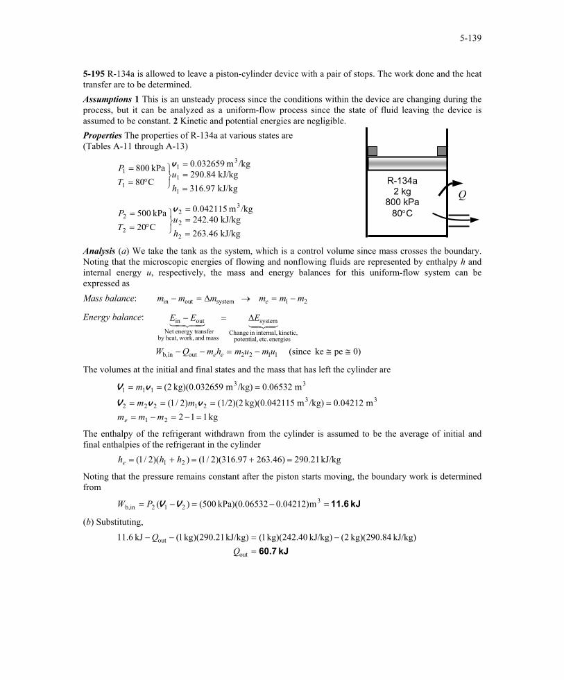
5-195 R-134a is allowed to leave a piston-cylinder device with a pair of stops. The work done and the heat transfer are to be determined. Assumptions 1 This is an unsteady process since the conditions within the device are changing during the process, but it can be analyzed as a uniform-flow process since the state of fluid leaving the device is assumed to be constant. 2 Kinetic and potential energies are negligible.
QR-134a
2 kg 800 kPa
80°C
Properties The properties of R-134a at various states are (Tables A-11 through A-13)
kJ/kg 97.316kJ/kg 84.290
/kgm 032659.0
C80kPa 800
1
1
31
1
1
===
°==
hu
TP v
kJ/kg 46.263kJ/kg 40.242
/kgm 042115.0
C20kPa 500
2
2
32
2
2
===
°==
hu
TP v
Analysis (a) We take the tank as the system, which is a control volume since mass crosses the boundary. Noting that the microscopic energies of flowing and nonflowing fluids are represented by enthalpy h and internal energy u, respectively, the mass and energy balances for this uniform-flow system can be expressed as Mass balance: 21systemoutin mmmmmm e −=→∆=−
Energy balance:
)0peke (since 1122outinb,
energies etc. potential, kinetic, internal,in Change
system
mass and work,heat,by nsferenergy traNet
outin
≅≅−=−−
∆=−
umumhmQW
EEE
ee
4342143421
The volumes at the initial and final states and the mass that has left the cylinder are
kg 112m 0.04212/kg)m 15kg)(0.0421 (1/2)(2)2/1(
m 0.06532/kg)m 59kg)(0.0326 (2
21
3321222
33111
=−=−=====
===
mmmmm
m
e
vvV
vV
The enthalpy of the refrigerant withdrawn from the cylinder is assumed to be the average of initial and final enthalpies of the refrigerant in the cylinder kJ/kg 21.290)46.26397.316)(2/1())(2/1( 21 =+=+= hhhe
Noting that the pressure remains constant after the piston starts moving, the boundary work is determined from
kJ 11.6=−=−= 3212inb, m)04212.006532.0(kPa) (500)( VVPW
(b) Substituting,
kJ 60.7=−=−−
out
out kJ/kg) kg)(290.84 2(kJ/kg) kg)(242.40 1(kJ/kg) kg)(290.21 1(kJ 6.11Q
Q
PROPRIETARY MATERIAL. © 2006 The McGraw-Hill Companies, Inc. Limited distribution permitted only to teachers and educators for course preparation. If you are a student using this Manual, you are using it without permission.
5-140
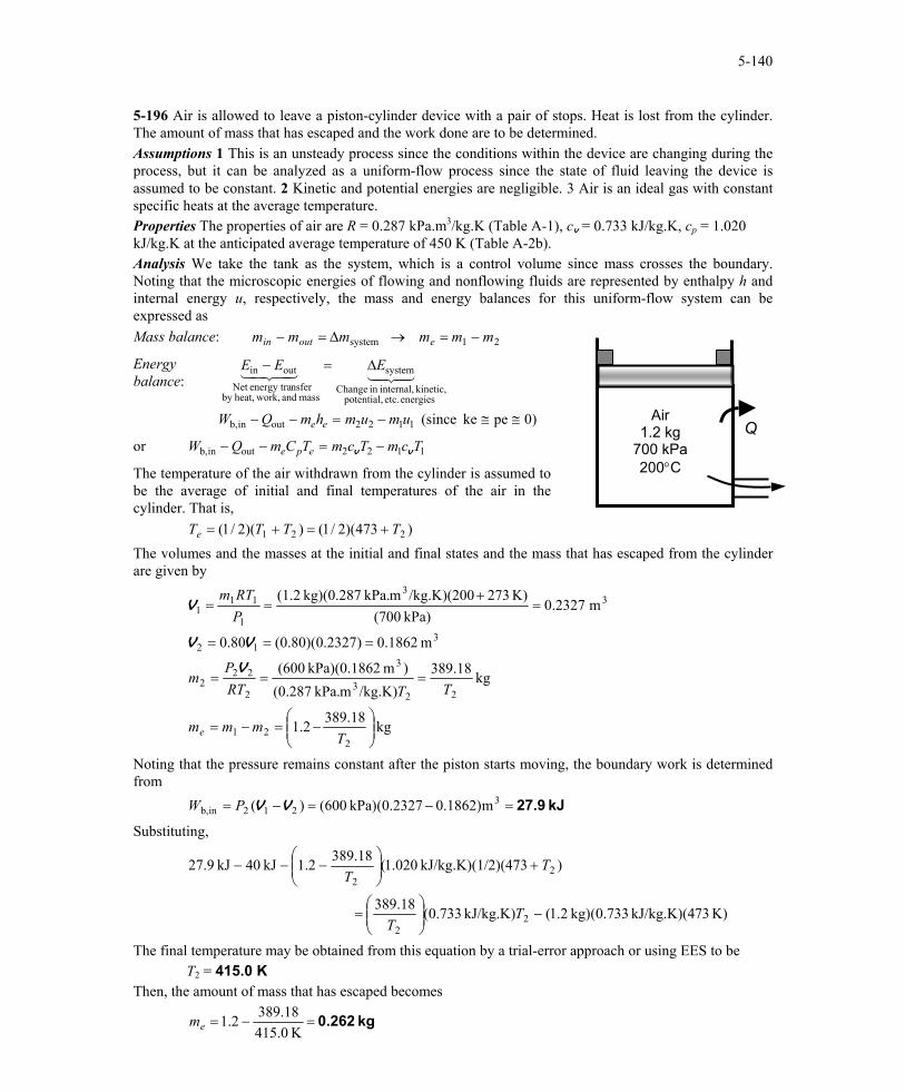
5-196 Air is allowed to leave a piston-cylinder device with a pair of stops. Heat is lost from the cylinder. The amount of mass that has escaped and the work done are to be determined. Assumptions 1 This is an unsteady process since the conditions within the device are changing during the process, but it can be analyzed as a uniform-flow process since the state of fluid leaving the device is assumed to be constant. 2 Kinetic and potential energies are negligible. 3 Air is an ideal gas with constant specific heats at the average temperature. Properties The properties of air are R = 0.287 kPa.m3/kg.K (Table A-1), cv = 0.733 kJ/kg.K, cp = 1.020 kJ/kg.K at the anticipated average temperature of 450 K (Table A-2b). Analysis We take the tank as the system, which is a control volume since mass crosses the boundary. Noting that the microscopic energies of flowing and nonflowing fluids are represented by enthalpy h and internal energy u, respectively, the mass and energy balances for this uniform-flow system can be expressed as Mass balance: 21system mmmmmm eoutin −=→∆=−
QAir
1.2 kg 700 kPa 200°C
Energy balance:
)0peke (since 1122outinb,
energies etc. potential, kinetic, internal,in Change
system
mass and work,heat,by nsferenergy traNet
outin
≅≅−=−−
∆=−
umumhmQW
EEE
ee
4342143421
or 1122outinb, TcmTcmTCmQW epe vv −=−−
The temperature of the air withdrawn from the cylinder is assumed to be the average of initial and final temperatures of the air in the cylinder. That is, )473)(2/1())(2/1( 221 TTTTe +=+= The volumes and the masses at the initial and final states and the mass that has escaped from the cylinder are given by
kg 18.3892.1
kg 18.389/kg.K)mkPa. (0.287
)m 2kPa)(0.186 (600
m 1862.0)2327.0)(80.0(80.0
m 2327.0kPa) (700
K) 273/kg.K)(200mkPa. kg)(0.287 (1.2
221
223
3
2
222
312
33
1
111
−=−=
===
===
=+
==
Tmmm
TTRTP
m
PRTm
e
V
VV
V
Noting that the pressure remains constant after the piston starts moving, the boundary work is determined from kJ 27.9=−=−= 3
212inb, m)1862.02327.0(kPa) (600)( VVPW
Substituting,
K) 73kJ/kg.K)(4 733.0(kg) 2.1(kJ/kg.K) 733.0(18.389
)/2)(473kJ/kg.K)(1 020.1(18.3892.1kJ 40kJ 9.27
22
22
−
=
+
−−−
TT
TT
The final temperature may be obtained from this equation by a trial-error approach or using EES to be T2 = 415.0 K Then, the amount of mass that has escaped becomes
kg 0.262=−=K 0.415
18.3892.1em
PROPRIETARY MATERIAL. © 2006 The McGraw-Hill Companies, Inc. Limited distribution permitted only to teachers and educators for course preparation. If you are a student using this Manual, you are using it without permission.

5-141
5-197 The pressures across a pump are measured. The mechanical efficiency of the pump and the temperature rise of water are to be determined. Assumptions 1 The flow is steady and incompressible. 2 The pump is driven by an external motor so that the heat generated by the motor is dissipated to the atmosphere. 3 The elevation difference between the inlet and outlet of the pump is negligible, z1 = z2. 4 The inlet and outlet diameters are the same and thus the inlet and exit velocities are equal, V1 = V2. Properties We take the density of water to be 1 kg/L = 1000 kg/m3 and its specific heat to be 4.18 kJ/kg · °C (Table A-3). Analysis (a) The mass flow rate of water through the pump is
kg/s 50L/s) kg/L)(50 1( === V&& ρm
The motor draws 15 kW of power and is 90 percent efficient. Thus the mechanical (shaft) power it delivers to the pump is
kW 5.13kW) 15)(90.0(electricmotorshaftpump, === WW && η
Motor
15 kW
Pump inlet
PUMP
To determine the mechanical efficiency of the pump, we need to know the increase in the mechanical energy of the fluid as it flows through the pump, which is
++−
++=−=∆ 1
211
2
222
inmech,outmech,fluidmech, 22gz
VPmgz
VPmEEE
ρρ&&&&&
Simplifying it for this case and substituting the given values,
kW 10mkPa 1
kJ 1kg/m 1000
kPa)100300(kg/s) 50(33
12fluidmech, =
⋅
−=
−=∆
ρPP
mE &&
Then the mechanical efficiency of the pump becomes
74.1%===∆
= 741.0kW 13.5
kW 10
shaftpump,
fluidmech,
W
Epump &
&η
(b) Of the 13.5-kW mechanical power supplied by the pump, only 10 kW is imparted to the fluid as mechanical energy. The remaining 3.5 kW is converted to thermal energy due to frictional effects, and this “lost” mechanical energy manifests itself as a heating effect in the fluid,
kW 5.3105.13fluidmech,shaftpump,lossmech, =−=∆−= EWE &&&
The temperature rise of water due to this mechanical inefficiency is determined from the thermal energy balance,
TcmuumE ∆=−= &&& )( 12lossmech,
Solving for ∆T,
C0.017°=⋅
==∆K)kJ/kg kg/s)(4.18 50(
kW 5.3lossmech,
cmE
T&
&
Therefore, the water will experience a temperature rise of 0.017°C, which is very small, as it flows through the pump. Discussion In an actual application, the temperature rise of water will probably be less since part of the heat generated will be transferred to the casing of the pump and from the casing to the surrounding air. If the entire pump motor were submerged in water, then the 1.5 kW dissipated to the air due to motor inefficiency would also be transferred to the surrounding water as heat. This would cause the water temperature to rise more.
PROPRIETARY MATERIAL. © 2006 The McGraw-Hill Companies, Inc. Limited distribution permitted only to teachers and educators for course preparation. If you are a student using this Manual, you are using it without permission.

5-142
5- 198 Heat is lost from the steam flowing in a nozzle. The exit velocity and the mass flow rate are to be determined. Assumptions 1 This is a steady-flow process since there is no change with time. 2 Potential energy change is negligible. 3 There are no work interactions. 75 kPa
Sat. vap.
q
STEAM 150°C 200 kPaAnalysis (a) We take the steam as the system, which is a
control volume since mass crosses the boundary. The energy balance for this steady-flow system can be expressed in the rate form as Energy balance:
0)pe since 22
0
out
22
2
21
1
outin
energies etc. potential, kinetic, internal,in change of Rate
(steady) 0system
mass and work,heat,by nsferenergy tranet of Rate
outin
≅∆≅+
+=
+
=
=∆=−
WQVhmVhm
EE
EEE
&&&&
&&
44 344 21&
43421&&
or )(2 out212 qhhV −−=
The properties of steam at the inlet and exit are (Table A-6)
kJ/kg 1.2769C150kPa 002
11
1 =
°==
hTP
kJ/kg 4.2662
/kgm 2172.2 vap.sat.
kPa 75
2
322
==
=
hP v
Substituting,
m/s 401.7=
−−=−−=
22out212/sm 1000
kJ/kg 1kJ/kg)264.26621.2769(2)(2 qhhV
(b) The mass flow rate of the steam is
kg/s 0.181=== m/s) )(401.7m (0.001/kgm 2.2172
11 2322
2VAm
v&
PROPRIETARY MATERIAL. © 2006 The McGraw-Hill Companies, Inc. Limited distribution permitted only to teachers and educators for course preparation. If you are a student using this Manual, you are using it without permission.

5-143
5-199 The turbocharger of an internal combustion engine consisting of a turbine, a compressor, and an aftercooler is considered. The temperature of the air at the compressor outlet and the minimum flow rate of ambient air are to be determined.
Cold air
Air
Exhaust gases Aftercooler
Turbine Compressor
Assumptions 1 All processes are steady since there is no change with time. 2 Kinetic and potential energy changes are negligible. 3 Air properties are used for exhaust gases. 4 Air is an ideal gas with constant specific heats. 5 The mechanical efficiency between the turbine and the compressor is 100%. 6 All devices are adiabatic. 7 The local atmospheric pressure is 100 kPa. Properties The constant pressure specific heats of exhaust gases, warm air, and cold ambient air are taken to be cp = 1.063, 1.008, and 1.005 kJ/kg·K, respectively (Table A-2b). Analysis (a) An energy balance on turbine gives
( ) kW 063.1350)KK)(400kJ/kg 3kg/s)(1.06 (0.02exh,2exh,1exh,exhT =−⋅=−= TTcmW p&&
This is also the power input to the compressor since the mechanical efficiency between the turbine and the compressor is assumed to be 100%. An energy balance on the compressor gives the air temperature at the compressor outlet
C 108.6 °=→−⋅=
−=
a,2a,2
a,1a,2a,aC
0)K5K)(kJ/kg 8kg/s)(1.00 (0.018kW 063.1
)(
TT
TTcmW p&&
(b) An energy balance on the aftercooler gives the mass flow rate of cold ambient air
kg/s 05161.0
C0)3C)(40kJ/kg (1.005C0)8C)(108.6kJ/kg 8kg/s)(1.00 (0.018
)()(
ca
ca
ca,1ca,2ca,caa,3a,2a,a
=°−°⋅=°−°⋅
−=−
mm
TTcmTTcm pp
&
&
&&
The volume flow rate may be determined if we first calculate specific volume of cold ambient air at the inlet of aftercooler. That is,
/kgm 8696.0kPa 100
K) 273K)(30kJ/kg 287.0( 3ca =
+⋅==
PRT
v
L/s 44.9/sm 0.0449 3 ==== /kg)m 8696.0kg/s)( 05161.0( 3caca vV m&&
PROPRIETARY MATERIAL. © 2006 The McGraw-Hill Companies, Inc. Limited distribution permitted only to teachers and educators for course preparation. If you are a student using this Manual, you are using it without permission.

5-144
Fundamentals of Engineering (FE) Exam Problems 5-200 Steam is accelerated by a nozzle steadily from a low velocity to a velocity of 210 m/s at a rate of 3.2 kg/s. If the temperature and pressure of the steam at the nozzle exit are 400°C and 2 MPa, the exit area of the nozzle is (a) 24.0 cm2 (b) 8.4 cm2 (c) 10.2 cm2 (d) 152 cm2 (e) 23.0 cm2 Answer (e) 23.0 cm2 Solution Solved by EES Software. Solutions can be verified by copying-and-pasting the following lines on a blank EES screen. (Similar problems and their solutions can be obtained easily by modifying numerical values). Vel_1=0 "m/s" Vel_2=210 "m/s" m=3.2 "kg/s" T2=400 "C" P2=2000 "kPa" "The rate form of energy balance is E_dot_in - E_dot_out = DELTAE_dot_cv" v2=VOLUME(Steam_IAPWS,T=T2,P=P2) m=(1/v2)*A2*Vel_2 "A2 in m^2" "Some Wrong Solutions with Common Mistakes:" R=0.4615 "kJ/kg.K" P2*v2ideal=R*(T2+273) m=(1/v2ideal)*W1_A2*Vel_2 "assuming ideal gas" P1*v2ideal=R*T2 m=(1/v2ideal)*W2_A2*Vel_2 "assuming ideal gas and using C" m=W3_A2*Vel_2 "not using specific volume" 5-201 Steam enters a diffuser steadily at 0.5 MPa, 300°C, and 122 m/s at a rate of 3.5 kg/s. The inlet area of the diffuser is (a) 15 cm2 (b) 50 cm2 (c) 105 cm2 (d) 150 cm2 (e) 190 cm2 Answer (b) 50 cm2 Solution Solved by EES Software. Solutions can be verified by copying-and-pasting the following lines on a blank EES screen. (Similar problems and their solutions can be obtained easily by modifying numerical values). Vel_1=122 "m/s" m=3.5 "kg/s" T1=300 "C" P1=500 "kPa" "The rate form of energy balance is E_dot_in - E_dot_out = DELTAE_dot_cv" v1=VOLUME(Steam_IAPWS,T=T1,P=P1) m=(1/v1)*A*Vel_1 "A in m^2" "Some Wrong Solutions with Common Mistakes:" R=0.4615 "kJ/kg.K"
PROPRIETARY MATERIAL. © 2006 The McGraw-Hill Companies, Inc. Limited distribution permitted only to teachers and educators for course preparation. If you are a student using this Manual, you are using it without permission.
5-145
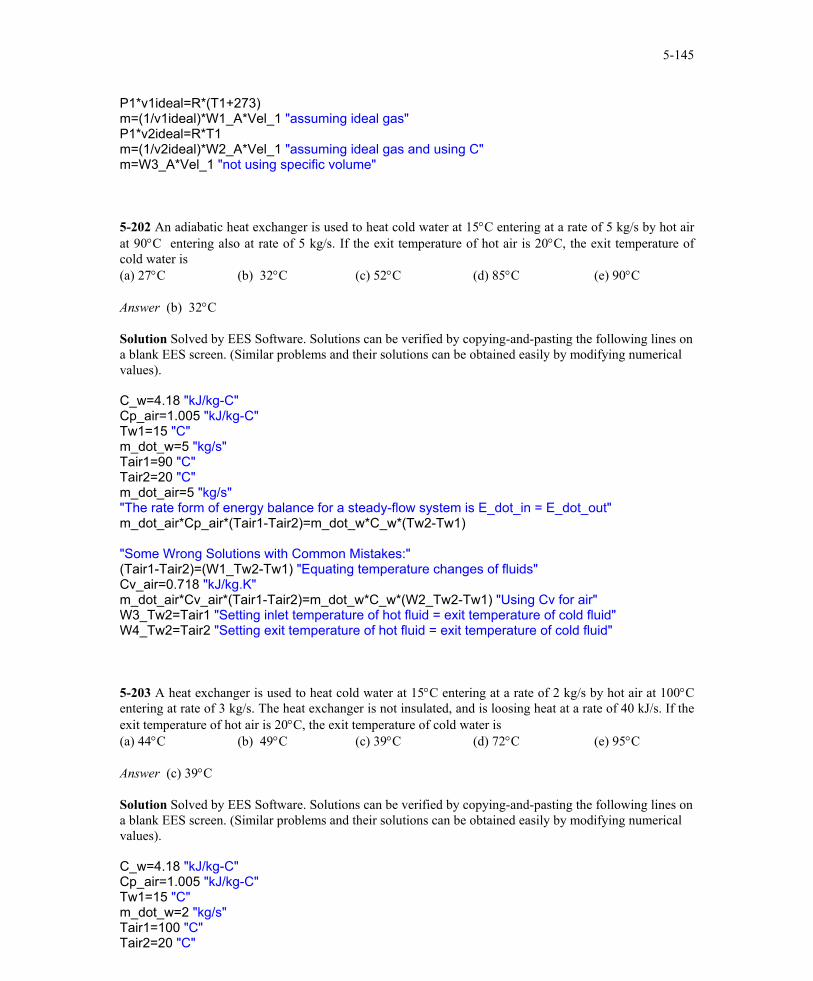
P1*v1ideal=R*(T1+273) m=(1/v1ideal)*W1_A*Vel_1 "assuming ideal gas" P1*v2ideal=R*T1 m=(1/v2ideal)*W2_A*Vel_1 "assuming ideal gas and using C" m=W3_A*Vel_1 "not using specific volume" 5-202 An adiabatic heat exchanger is used to heat cold water at 15°C entering at a rate of 5 kg/s by hot air at 90°C entering also at rate of 5 kg/s. If the exit temperature of hot air is 20°C, the exit temperature of cold water is (a) 27°C (b) 32°C (c) 52°C (d) 85°C (e) 90°C Answer (b) 32°C Solution Solved by EES Software. Solutions can be verified by copying-and-pasting the following lines on a blank EES screen. (Similar problems and their solutions can be obtained easily by modifying numerical values). C_w=4.18 "kJ/kg-C" Cp_air=1.005 "kJ/kg-C" Tw1=15 "C" m_dot_w=5 "kg/s" Tair1=90 "C" Tair2=20 "C" m_dot_air=5 "kg/s" "The rate form of energy balance for a steady-flow system is E_dot_in = E_dot_out" m_dot_air*Cp_air*(Tair1-Tair2)=m_dot_w*C_w*(Tw2-Tw1) "Some Wrong Solutions with Common Mistakes:" (Tair1-Tair2)=(W1_Tw2-Tw1) "Equating temperature changes of fluids" Cv_air=0.718 "kJ/kg.K" m_dot_air*Cv_air*(Tair1-Tair2)=m_dot_w*C_w*(W2_Tw2-Tw1) "Using Cv for air" W3_Tw2=Tair1 "Setting inlet temperature of hot fluid = exit temperature of cold fluid" W4_Tw2=Tair2 "Setting exit temperature of hot fluid = exit temperature of cold fluid"
5-203 A heat exchanger is used to heat cold water at 15°C entering at a rate of 2 kg/s by hot air at 100°C entering at rate of 3 kg/s. The heat exchanger is not insulated, and is loosing heat at a rate of 40 kJ/s. If the exit temperature of hot air is 20°C, the exit temperature of cold water is (a) 44°C (b) 49°C (c) 39°C (d) 72°C (e) 95°C Answer (c) 39°C Solution Solved by EES Software. Solutions can be verified by copying-and-pasting the following lines on a blank EES screen. (Similar problems and their solutions can be obtained easily by modifying numerical values). C_w=4.18 "kJ/kg-C" Cp_air=1.005 "kJ/kg-C" Tw1=15 "C" m_dot_w=2 "kg/s" Tair1=100 "C" Tair2=20 "C"
PROPRIETARY MATERIAL. © 2006 The McGraw-Hill Companies, Inc. Limited distribution permitted only to teachers and educators for course preparation. If you are a student using this Manual, you are using it without permission.

5-146
m_dot_air=3 "kg/s" Q_loss=40 "kJ/s" "The rate form of energy balance for a steady-flow system is E_dot_in = E_dot_out" m_dot_air*Cp_air*(Tair1-Tair2)=m_dot_w*C_w*(Tw2-Tw1)+Q_loss "Some Wrong Solutions with Common Mistakes:" m_dot_air*Cp_air*(Tair1-Tair2)=m_dot_w*C_w*(W1_Tw2-Tw1) "Not considering Q_loss" m_dot_air*Cp_air*(Tair1-Tair2)=m_dot_w*C_w*(W2_Tw2-Tw1)-Q_loss "Taking heat loss as heat gain" (Tair1-Tair2)=(W3_Tw2-Tw1) "Equating temperature changes of fluids" Cv_air=0.718 "kJ/kg.K" m_dot_air*Cv_air*(Tair1-Tair2)=m_dot_w*C_w*(W4_Tw2-Tw1)+Q_loss "Using Cv for air"
5-204 An adiabatic heat exchanger is used to heat cold water at 15°C entering at a rate of 5 kg/s by hot water at 90°C entering at rate of 4 kg/s. If the exit temperature of hot water is 50°C, the exit temperature of cold water is (a) 42°C (b) 47°C (c) 55°C (d) 78°C (e) 90°C Answer (b) 47°C Solution Solved by EES Software. Solutions can be verified by copying-and-pasting the following lines on a blank EES screen. (Similar problems and their solutions can be obtained easily by modifying numerical values). C_w=4.18 "kJ/kg-C" Tcold_1=15 "C" m_dot_cold=5 "kg/s" Thot_1=90 "C" Thot_2=50 "C" m_dot_hot=4 "kg/s" Q_loss=0 "kJ/s" "The rate form of energy balance for a steady-flow system is E_dot_in = E_dot_out" m_dot_hot*C_w*(Thot_1-Thot_2)=m_dot_cold*C_w*(Tcold_2-Tcold_1)+Q_loss "Some Wrong Solutions with Common Mistakes:" Thot_1-Thot_2=W1_Tcold_2-Tcold_1 "Equating temperature changes of fluids" W2_Tcold_2=90 "Taking exit temp of cold fluid=inlet temp of hot fluid" 5-205 In a shower, cold water at 10°C flowing at a rate of 5 kg/min is mixed with hot water at 60°C flowing at a rate of 2 kg/min. The exit temperature of the mixture will be (a) 24.3°C (b) 35.0°C (c) 40.0°C (d) 44.3°C (e) 55.2°C Answer (a) 24.3°C Solution Solved by EES Software. Solutions can be verified by copying-and-pasting the following lines on a blank EES screen. (Similar problems and their solutions can be obtained easily by modifying numerical values). C_w=4.18 "kJ/kg-C" Tcold_1=10 "C" m_dot_cold=5 "kg/min"
PROPRIETARY MATERIAL. © 2006 The McGraw-Hill Companies, Inc. Limited distribution permitted only to teachers and educators for course preparation. If you are a student using this Manual, you are using it without permission.

5-147
Thot_1=60 "C" m_dot_hot=2 "kg/min" "The rate form of energy balance for a steady-flow system is E_dot_in = E_dot_out" m_dot_hot*C_w*Thot_1+m_dot_cold*C_w*Tcold_1=(m_dot_hot+m_dot_cold)*C_w*Tmix "Some Wrong Solutions with Common Mistakes:" W1_Tmix=(Tcold_1+Thot_1)/2 "Taking the average temperature of inlet fluids" 5-206 In a heating system, cold outdoor air at 10°C flowing at a rate of 6 kg/min is mixed adiabatically with heated air at 70°C flowing at a rate of 3 kg/min. The exit temperature of the mixture is (a) 30°C (b) 40°C (c) 45°C (d) 55°C (e) 85°C Answer (a) 30°C Solution Solved by EES Software. Solutions can be verified by copying-and-pasting the following lines on a blank EES screen. (Similar problems and their solutions can be obtained easily by modifying numerical values). C_air=1.005 "kJ/kg-C" Tcold_1=10 "C" m_dot_cold=6 "kg/min" Thot_1=70 "C" m_dot_hot=3 "kg/min" "The rate form of energy balance for a steady-flow system is E_dot_in = E_dot_out" m_dot_hot*C_air*Thot_1+m_dot_cold*C_air*Tcold_1=(m_dot_hot+m_dot_cold)*C_air*Tmix "Some Wrong Solutions with Common Mistakes:" W1_Tmix=(Tcold_1+Thot_1)/2 "Taking the average temperature of inlet fluids" 5-207 Hot combustion gases (assumed to have the properties of air at room temperature) enter a gas turbine at 1 MPa and 1500 K at a rate of 0.1 kg/s, and exit at 0.2 MPa and 900 K. If heat is lost from the turbine to the surroundings at a rate of 15 kJ/s, the power output of the gas turbine is (a) 15 kW (b) 30 kW (c) 45 kW (d) 60 kW (e) 75 kW Answer (c) 45 kW Solution Solved by EES Software. Solutions can be verified by copying-and-pasting the following lines on a blank EES screen. (Similar problems and their solutions can be obtained easily by modifying numerical values). Cp_air=1.005 "kJ/kg-C" T1=1500 "K" T2=900 "K" m_dot=0.1 "kg/s" Q_dot_loss=15 "kJ/s" "The rate form of energy balance for a steady-flow system is E_dot_in = E_dot_out" W_dot_out+Q_dot_loss=m_dot*Cp_air*(T1-T2) "Alternative: Variable specific heats - using EES data" W_dot_outvariable+Q_dot_loss=m_dot*(ENTHALPY(Air,T=T1)-ENTHALPY(Air,T=T2)) "Some Wrong Solutions with Common Mistakes:" W1_Wout=m_dot*Cp_air*(T1-T2) "Disregarding heat loss" W2_Wout-Q_dot_loss=m_dot*Cp_air*(T1-T2) "Assuming heat gain instead of loss"
PROPRIETARY MATERIAL. © 2006 The McGraw-Hill Companies, Inc. Limited distribution permitted only to teachers and educators for course preparation. If you are a student using this Manual, you are using it without permission.
5-148
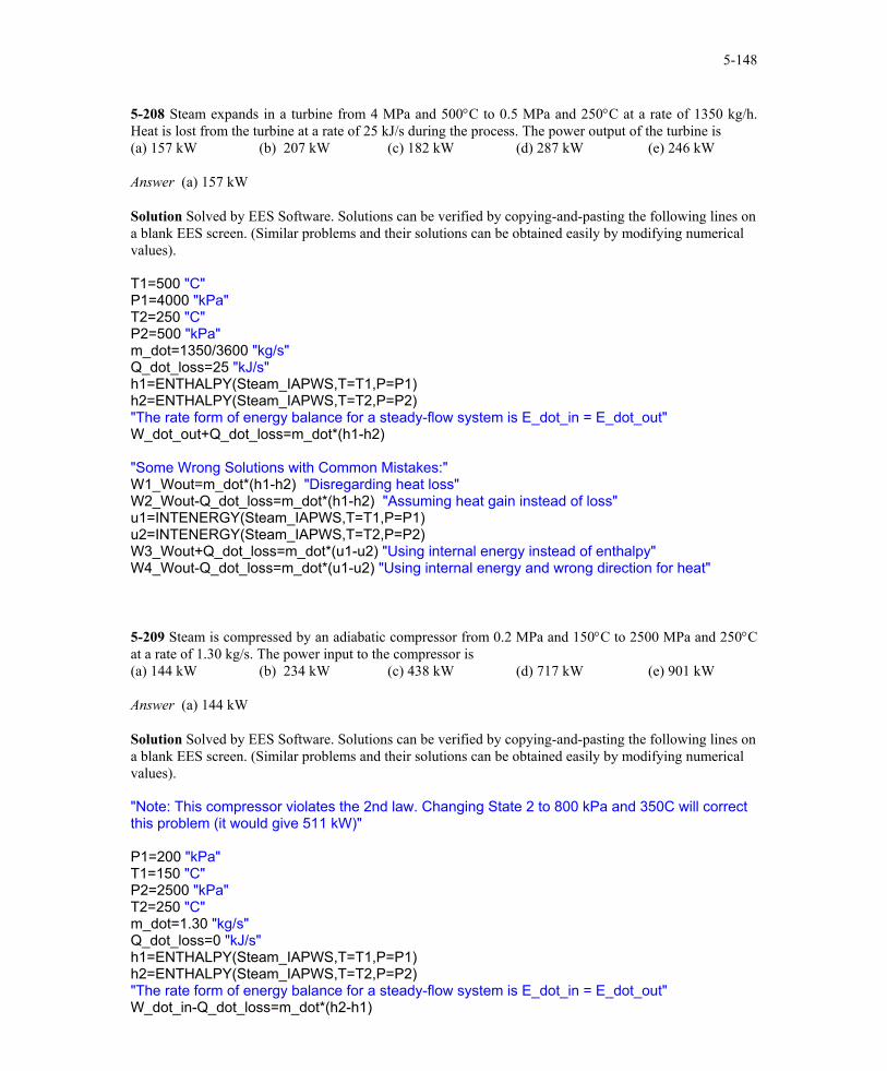
5-208 Steam expands in a turbine from 4 MPa and 500°C to 0.5 MPa and 250°C at a rate of 1350 kg/h. Heat is lost from the turbine at a rate of 25 kJ/s during the process. The power output of the turbine is (a) 157 kW (b) 207 kW (c) 182 kW (d) 287 kW (e) 246 kW Answer (a) 157 kW Solution Solved by EES Software. Solutions can be verified by copying-and-pasting the following lines on a blank EES screen. (Similar problems and their solutions can be obtained easily by modifying numerical values). T1=500 "C" P1=4000 "kPa" T2=250 "C" P2=500 "kPa" m_dot=1350/3600 "kg/s" Q_dot_loss=25 "kJ/s" h1=ENTHALPY(Steam_IAPWS,T=T1,P=P1) h2=ENTHALPY(Steam_IAPWS,T=T2,P=P2) "The rate form of energy balance for a steady-flow system is E_dot_in = E_dot_out" W_dot_out+Q_dot_loss=m_dot*(h1-h2) "Some Wrong Solutions with Common Mistakes:" W1_Wout=m_dot*(h1-h2) "Disregarding heat loss" W2_Wout-Q_dot_loss=m_dot*(h1-h2) "Assuming heat gain instead of loss" u1=INTENERGY(Steam_IAPWS,T=T1,P=P1) u2=INTENERGY(Steam_IAPWS,T=T2,P=P2) W3_Wout+Q_dot_loss=m_dot*(u1-u2) "Using internal energy instead of enthalpy" W4_Wout-Q_dot_loss=m_dot*(u1-u2) "Using internal energy and wrong direction for heat" 5-209 Steam is compressed by an adiabatic compressor from 0.2 MPa and 150°C to 2500 MPa and 250°C at a rate of 1.30 kg/s. The power input to the compressor is (a) 144 kW (b) 234 kW (c) 438 kW (d) 717 kW (e) 901 kW Answer (a) 144 kW Solution Solved by EES Software. Solutions can be verified by copying-and-pasting the following lines on a blank EES screen. (Similar problems and their solutions can be obtained easily by modifying numerical values). "Note: This compressor violates the 2nd law. Changing State 2 to 800 kPa and 350C will correct this problem (it would give 511 kW)" P1=200 "kPa" T1=150 "C" P2=2500 "kPa" T2=250 "C" m_dot=1.30 "kg/s" Q_dot_loss=0 "kJ/s" h1=ENTHALPY(Steam_IAPWS,T=T1,P=P1) h2=ENTHALPY(Steam_IAPWS,T=T2,P=P2) "The rate form of energy balance for a steady-flow system is E_dot_in = E_dot_out" W_dot_in-Q_dot_loss=m_dot*(h2-h1)
PROPRIETARY MATERIAL. © 2006 The McGraw-Hill Companies, Inc. Limited distribution permitted only to teachers and educators for course preparation. If you are a student using this Manual, you are using it without permission.

5-149
"Some Wrong Solutions with Common Mistakes:" W1_Win-Q_dot_loss=(h2-h1)/m_dot "Dividing by mass flow rate instead of multiplying" W2_Win-Q_dot_loss=h2-h1 "Not considering mass flow rate" u1=INTENERGY(Steam_IAPWS,T=T1,P=P1) u2=INTENERGY(Steam_IAPWS,T=T2,P=P2) W3_Win-Q_dot_loss=m_dot*(u2-u1) "Using internal energy instead of enthalpy" W4_Win-Q_dot_loss=u2-u1 "Using internal energy and ignoring mass flow rate" 5-210 Refrigerant-134a is compressed by a compressor from the saturated vapor state at 0.14 MPa to 1.2 MPa and 70°C at a rate of 0.108 kg/s. The refrigerant is cooled at a rate of 1.10 kJ/s during compression. The power input to the compressor is (a) 5.54 kW (b) 7.33 kW (c) 6.64 kW (d) 7.74 kW (e) 8.13 kW Answer (d) 7.74 kW Solution Solved by EES Software. Solutions can be verified by copying-and-pasting the following lines on a blank EES screen. (Similar problems and their solutions can be obtained easily by modifying numerical values). P1=140 "kPa" x1=1 P2=1200 "kPa" T2=70 "C" m_dot=0.108 "kg/s" Q_dot_loss=1.10 "kJ/s" h1=ENTHALPY(R134a,x=x1,P=P1) h2=ENTHALPY(R134a,T=T2,P=P2) "The rate form of energy balance for a steady-flow system is E_dot_in = E_dot_out" W_dot_in-Q_dot_loss=m_dot*(h2-h1) "Some Wrong Solutions with Common Mistakes:" W1_Win+Q_dot_loss=m_dot*(h2-h1) "Wrong direction for heat transfer" W2_Win =m_dot*(h2-h1) "Not considering heat loss" u1=INTENERGY(R134a,x=x1,P=P1) u2=INTENERGY(R134a,T=T2,P=P2) W3_Win-Q_dot_loss=m_dot*(u2-u1) "Using internal energy instead of enthalpy" W4_Win+Q_dot_loss=u2-u1 "Using internal energy and wrong direction for heat transfer" 5-211 Refrigerant-134a expands in an adiabatic turbine from 1.2 MPa and 100°C to 0.18 MPa and 50°C at a rate of 1.25 kg/s. The power output of the turbine is (a) 46.3 kW (b) 66.4 kW (c) 72.7 kW (d) 89.2 kW (e) 112.0 kW Answer (a) 46.3 kW Solution Solved by EES Software. Solutions can be verified by copying-and-pasting the following lines on a blank EES screen. (Similar problems and their solutions can be obtained easily by modifying numerical values). P1=1200 "kPa" T1=100 "C" P2=180 "kPa"
PROPRIETARY MATERIAL. © 2006 The McGraw-Hill Companies, Inc. Limited distribution permitted only to teachers and educators for course preparation. If you are a student using this Manual, you are using it without permission.
5-150
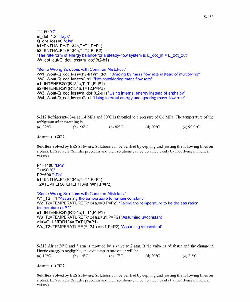
T2=50 "C" m_dot=1.25 "kg/s" Q_dot_loss=0 "kJ/s" h1=ENTHALPY(R134a,T=T1,P=P1) h2=ENTHALPY(R134a,T=T2,P=P2) "The rate form of energy balance for a steady-flow system is E_dot_in = E_dot_out" -W_dot_out-Q_dot_loss=m_dot*(h2-h1) "Some Wrong Solutions with Common Mistakes:" -W1_Wout-Q_dot_loss=(h2-h1)/m_dot "Dividing by mass flow rate instead of multiplying" -W2_Wout-Q_dot_loss=h2-h1 "Not considering mass flow rate" u1=INTENERGY(R134a,T=T1,P=P1) u2=INTENERGY(R134a,T=T2,P=P2) -W3_Wout-Q_dot_loss=m_dot*(u2-u1) "Using internal energy instead of enthalpy" -W4_Wout-Q_dot_loss=u2-u1 "Using internal energy and ignoring mass flow rate" 5-212 Refrigerant-134a at 1.4 MPa and 90°C is throttled to a pressure of 0.6 MPa. The temperature of the refrigerant after throttling is (a) 22°C (b) 56°C (c) 82°C (d) 80°C (e) 90.0°C Answer (d) 80°C Solution Solved by EES Software. Solutions can be verified by copying-and-pasting the following lines on a blank EES screen. (Similar problems and their solutions can be obtained easily by modifying numerical values). P1=1400 "kPa" T1=90 "C" P2=600 "kPa" h1=ENTHALPY(R134a,T=T1,P=P1) T2=TEMPERATURE(R134a,h=h1,P=P2) "Some Wrong Solutions with Common Mistakes:" W1_T2=T1 "Assuming the temperature to remain constant" W2_T2=TEMPERATURE(R134a,x=0,P=P2) "Taking the temperature to be the saturation temperature at P2" u1=INTENERGY(R134a,T=T1,P=P1) W3_T2=TEMPERATURE(R134a,u=u1,P=P2) "Assuming u=constant" v1=VOLUME(R134a,T=T1,P=P1) W4_T2=TEMPERATURE(R134a,v=v1,P=P2) "Assuming v=constant" 5-213 Air at 20°C and 5 atm is throttled by a valve to 2 atm. If the valve is adiabatic and the change in kinetic energy is negligible, the exit temperature of air will be (a) 10°C (b) 14°C (c) 17°C (d) 20°C (e) 24°C Answer (d) 20°C Solution Solved by EES Software. Solutions can be verified by copying-and-pasting the following lines on a blank EES screen. (Similar problems and their solutions can be obtained easily by modifying numerical values).
PROPRIETARY MATERIAL. © 2006 The McGraw-Hill Companies, Inc. Limited distribution permitted only to teachers and educators for course preparation. If you are a student using this Manual, you are using it without permission.
5-151
"The temperature of an ideal gas remains constant during throttling, and thus T2=T1" T1=20 "C" P1=5 "atm" P2=2 "atm" T2=T1 "C" "Some Wrong Solutions with Common Mistakes:" W1_T2=T1*P1/P2 "Assuming v=constant and using C" W2_T2=(T1+273)*P1/P2-273 "Assuming v=constant and using K" W3_T2=T1*P2/P1 "Assuming v=constant and pressures backwards and using C" W4_T2=(T1+273)*P2/P1 "Assuming v=constant and pressures backwards and using K"
5-214 Steam at 1 MPa and 300°C is throttled adiabatically to a pressure of 0.4 MPa. If the change in kinetic energy is negligible, the specific volume of the steam after throttling will be (a) 0.358 m3/kg (b) 0.233 m3/kg (c) 0.375 m3/kg (d) 0.646 m3/kg (e) 0.655 m3/kg Answer (d) 0.646 m3/kg Solution Solved by EES Software. Solutions can be verified by copying-and-pasting the following lines on a blank EES screen. (Similar problems and their solutions can be obtained easily by modifying numerical values). P1=1000 "kPa" T1=300 "C" P2=400 "kPa" h1=ENTHALPY(Steam_IAPWS,T=T1,P=P1) v2=VOLUME(Steam_IAPWS,h=h1,P=P2) "Some Wrong Solutions with Common Mistakes:" W1_v2=VOLUME(Steam_IAPWS,T=T1,P=P2) "Assuming the volume to remain constant" u1=INTENERGY(Steam,T=T1,P=P1) W2_v2=VOLUME(Steam_IAPWS,u=u1,P=P2) "Assuming u=constant" W3_v2=VOLUME(Steam_IAPWS,T=T1,P=P2) "Assuming T=constant" 5-215 Air is to be heated steadily by an 8-kW electric resistance heater as it flows through an insulated duct. If the air enters at 50°C at a rate of 2 kg/s, the exit temperature of air will be (a) 46.0°C (b) 50.0°C (c) 54.0°C (d) 55.4°C (e) 58.0°C Answer (c) 54.0°C Solution Solved by EES Software. Solutions can be verified by copying-and-pasting the following lines on a blank EES screen. (Similar problems and their solutions can be obtained easily by modifying numerical values). Cp=1.005 "kJ/kg-C" T1=50 "C" m_dot=2 "kg/s" W_dot_e=8 "kJ/s" W_dot_e=m_dot*Cp*(T2-T1) "Checking using data from EES table"
PROPRIETARY MATERIAL. © 2006 The McGraw-Hill Companies, Inc. Limited distribution permitted only to teachers and educators for course preparation. If you are a student using this Manual, you are using it without permission.
5-152
W_dot_e=m_dot*(ENTHALPY(Air,T=T_2table)-ENTHALPY(Air,T=T1)) "Some Wrong Solutions with Common Mistakes:" Cv=0.718 "kJ/kg.K" W_dot_e=Cp*(W1_T2-T1) "Not using mass flow rate" W_dot_e=m_dot*Cv*(W2_T2-T1) "Using Cv" W_dot_e=m_dot*Cp*W3_T2 "Ignoring T1" 5-216 Saturated water vapor at 50°C is to be condensed as it flows through a tube at a rate of 0.35 kg/s. The condensate leaves the tube as a saturated liquid at 50°C. The rate of heat transfer from the tube is (a) 73 kJ/s (b) 980 kJ/s (c) 2380 kJ/s (d) 834 kJ/s (e) 907 kJ/s Answer (d) 834 kJ/s Solution Solved by EES Software. Solutions can be verified by copying-and-pasting the following lines on a blank EES screen. (Similar problems and their solutions can be obtained easily by modifying numerical values). T1=50 "C" m_dot=0.35 "kg/s" h_f=ENTHALPY(Steam_IAPWS,T=T1,x=0) h_g=ENTHALPY(Steam_IAPWS,T=T1,x=1) h_fg=h_g-h_f Q_dot=m_dot*h_fg "Some Wrong Solutions with Common Mistakes:" W1_Q=m_dot*h_f "Using hf" W2_Q=m_dot*h_g "Using hg" W3_Q=h_fg "not using mass flow rate" W4_Q=m_dot*(h_f+h_g) "Adding hf and hg" 5-217, 5-218 Design and Essay Problems
PROPRIETARY MATERIAL. © 2006 The McGraw-Hill Companies, Inc. Limited distribution permitted only to teachers and educators for course preparation. If you are a student using this Manual, you are using it without permission.


![arXiv:hep-th/9910071v1 7 Oct 1999 · may not be BPS saturated. The issue of the BPS saturation requires a separate dynamical consideration [6]. A general theory of the BPS saturated](https://static.fdocuments.us/doc/165x107/601848e9d8e33e3e3b1f4525/arxivhep-th9910071v1-7-oct-1999-may-not-be-bps-saturated-the-issue-of-the-bps.jpg)