5-1 Chapter 5- Datapath and Control Computer Architecture and...
38
5-1 Chapter 5 - Datapath and Control Computer Architecture and Organization by M. Murdocca and V. Heuring © 2007 M. Murdocca and V. Heuring Computer Architecture and Organization Miles Murdocca and Vincent Heuring Chapter 5 – Datapath and Control
Transcript of 5-1 Chapter 5- Datapath and Control Computer Architecture and...

5-1 Chapter 5 - Datapath and Control
Computer Architecture and Organization by M. Murdocca and V. Heuring © 2007 M. Murdocca and V. Heuring
Computer Architecture andOrganization
Miles Murdocca and Vincent Heuring
Chapter 5 – Datapathand Control

5-2 Chapter 5 - Datapath and Control
Computer Architecture and Organization by M. Murdocca and V. Heuring © 2007 M. Murdocca and V. Heuring
Chapter Contents5.1 Basics of the Microarchitecture5.2 The Datapath5.3 The Control Section – Microprogrammed5.4 The Control Section – Hardwired5.5 Case Study: The VHDL Hardware Description Language5.6 Case Study: What Happens when a Computer Boots Up?

5-3 Chapter 5 - Datapath and Control
Computer Architecture and Organization by M. Murdocca and V. Heuring © 2007 M. Murdocca and V. Heuring
The Fetch-Execute Cycle• The steps that the control unit carries out in executing a
program are:
(1) Fetch the next instruction to be executed from memory.
(2) Decode the opcode.
(3) Read operand(s) from main memory, if any.
(4) Execute the instruction and store results, if any.
(5) Go to step 1.

5-4 Chapter 5 - Datapath and Control
Computer Architecture and Organization by M. Murdocca and V. Heuring © 2007 M. Murdocca and V. Heuring
High Level View of Microarchitecture• The microarchitecture consists of the control unit and the
programmer-visible registers, functional units such as theALU, and any additional registers that may be required bythe control unit.

5-5 Chapter 5 - Datapath and Control
Computer Architecture and Organization by M. Murdocca and V. Heuring © 2007 M. Murdocca and V. Heuring
A More Detailed View

5-6 Chapter 5 - Datapath and Control
Computer Architecture and Organization by M. Murdocca and V. Heuring © 2007 M. Murdocca and V. Heuring
ARC Instruction Subset

5-7 Chapter 5 - Datapath and Control
Computer Architecture and Organization by M. Murdocca and V. Heuring © 2007 M. Murdocca and V. Heuring
ARC Instruction Formats

5-8 Chapter 5 - Datapath and Control
Computer Architecture and Organization by M. Murdocca and V. Heuring © 2007 M. Murdocca and V. Heuring
ARCDatapath

5-9 Chapter 5 - Datapath and Control
Computer Architecture and Organization by M. Murdocca and V. Heuring © 2007 M. Murdocca and V. Heuring
ARC ALU Operations

5-10 Chapter 5 - Datapath and Control
Computer Architecture and Organization by M. Murdocca and V. Heuring © 2007 M. Murdocca and V. Heuring
Block Diagram of ALU

5-11 Chapter 5 - Datapath and Control
Computer Architecture and Organization by M. Murdocca and V. Heuring © 2007 M. Murdocca and V. Heuring
Gate-Level Layout of Barrel Shifter

5-12 Chapter 5 - Datapath and Control
Computer Architecture and Organization by M. Murdocca and V. Heuring © 2007 M. Murdocca and V. Heuring
Truth Table for (Most of the) ALU LUTs

5-13 Chapter 5 - Datapath and Control
Computer Architecture and Organization by M. Murdocca and V. Heuring © 2007 M. Murdocca and V. Heuring
Design of Register %r1

5-14 Chapter 5 - Datapath and Control
Computer Architecture and Organization by M. Murdocca and V. Heuring © 2007 M. Murdocca and V. Heuring
Outputs to Control Unit fromRegister %ir

5-15 Chapter 5 - Datapath and Control
Computer Architecture and Organization by M. Murdocca and V. Heuring © 2007 M. Murdocca and V. Heuring
Microarch-itecture ofthe ARC

5-16 Chapter 5 - Datapath and Control
Computer Architecture and Organization by M. Murdocca and V. Heuring © 2007 M. Murdocca and V. Heuring
Microword Format

5-17 Chapter 5 - Datapath and Control
Computer Architecture and Organization by M. Murdocca and V. Heuring © 2007 M. Murdocca and V. Heuring
Settings for the COND Field of theMicroword
5-18 Chapter 5 - Datapath and Control
Computer Architecture and Organization by M. Murdocca and V. Heuring © 2007 M. Murdocca and V. Heuring
DECODE Format for MicroinstructionAddress
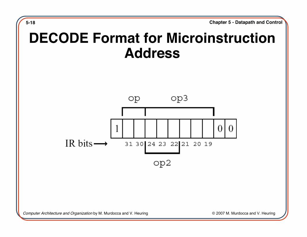
5-19 Chapter 5 - Datapath and Control
Computer Architecture and Organization by M. Murdocca and V. Heuring © 2007 M. Murdocca and V. Heuring
Timing Relationships for the Registers

5-20 Chapter 5 - Datapath and Control
Computer Architecture and Organization by M. Murdocca and V. Heuring © 2007 M. Murdocca and V. Heuring
PartialARC
Micro-program

5-21 Chapter 5 - Datapath and Control
Computer Architecture and Organization by M. Murdocca and V. Heuring © 2007 M. Murdocca and V. Heuring
Partial ARCMicroprogram
(cont’)

5-22 Chapter 5 - Datapath and Control
Computer Architecture and Organization by M. Murdocca and V. Heuring © 2007 M. Murdocca and V. Heuring
Translating the Microprogram0: R[ir] ← AND(R[pc],R[pc]); READ;
1: DECODE; /256-way jump according to opcode

5-23 Chapter 5 - Datapath and Control
Computer Architecture and Organization by M. Murdocca and V. Heuring © 2007 M. Murdocca and V. Heuring
Branch Decoding• Decoding tree for
branch instructionsshows correspondingmicroprogram lines:
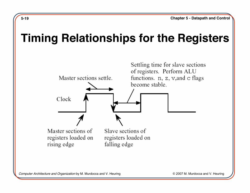
5-24 Chapter 5 - Datapath and Control
Computer Architecture and Organization by M. Murdocca and V. Heuring © 2007 M. Murdocca and V. Heuring
AssembledARC
Microprogram

5-25 Chapter 5 - Datapath and Control
Computer Architecture and Organization by M. Murdocca and V. Heuring © 2007 M. Murdocca and V. Heuring
AssembledARC
Microprogram(cont’)

5-26 Chapter 5 - Datapath and Control
Computer Architecture and Organization by M. Murdocca and V. Heuring © 2007 M. Murdocca and V. Heuring
Example: Add the subcc Instruction• Consider adding instruction subcc (subtract) to the ARC instruction set.subcc uses the Arithmetic format and op3 = 001100.

5-27 Chapter 5 - Datapath and Control
Computer Architecture and Organization by M. Murdocca and V. Heuring © 2007 M. Murdocca and V. Heuring
Branch Table• A branch table for trap handlers and interrupt service routines:

5-28 Chapter 5 - Datapath and Control
Computer Architecture and Organization by M. Murdocca and V. Heuring © 2007 M. Murdocca and V. Heuring
Microprogramming vs.Nanoprogramming
(a) Micropro-gramming,
(b) nano-programming.

5-29 Chapter 5 - Datapath and Control
Computer Architecture and Organization by M. Murdocca and V. Heuring © 2007 M. Murdocca and V. Heuring
Hardware Description Language
• HDL sequencefor a resettablemodulo 4counter.

5-30 Chapter 5 - Datapath and Control
Computer Architecture and Organization by M. Murdocca and V. Heuring © 2007 M. Murdocca and V. Heuring
Circuit Derived from HDL• Logic design for a modulo 4 counter described in HDL.

5-31 Chapter 5 - Datapath and Control
Computer Architecture and Organization by M. Murdocca and V. Heuring © 2007 M. Murdocca and V. Heuring
HDL forARC
• HDL description ofthe ARC controlunit.

5-32 Chapter 5 - Datapath and Control
Computer Architecture and Organization by M. Murdocca and V. Heuring © 2007 M. Murdocca and V. Heuring
HDL for ARC (cont’)

5-33 Chapter 5 - Datapath and Control
Computer Architecture and Organization by M. Murdocca and V. Heuring © 2007 M. Murdocca and V. Heuring
HDL ARCCircuit
• The hardwiredcontrol section ofthe ARC:generation of thecontrol signals.

5-34 Chapter 5 - Datapath and Control
Computer Architecture and Organization by M. Murdocca and V. Heuring © 2007 M. Murdocca and V. Heuring
HDL ARC Circuit (cont’)• Hardwired
controlsection ofthe ARC:signals fromthe datasection ofthe controlunit to thedatapath.
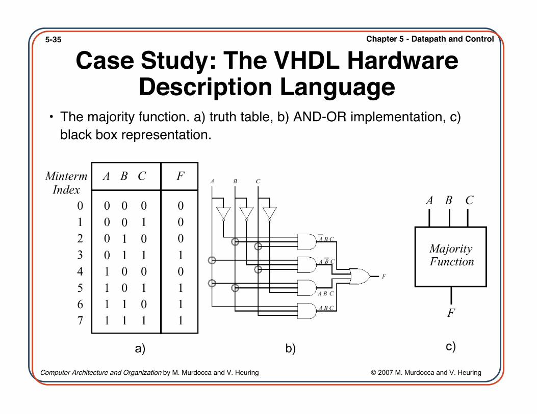
5-35 Chapter 5 - Datapath and Control
Computer Architecture and Organization by M. Murdocca and V. Heuring © 2007 M. Murdocca and V. Heuring
Case Study: The VHDL HardwareDescription Language
• The majority function. a) truth table, b) AND-OR implementation, c)black box representation.

5-36 Chapter 5 - Datapath and Control
Computer Architecture and Organization by M. Murdocca and V. Heuring © 2007 M. Murdocca and V. Heuring
VHDL SpecificationInterface specification for the majority component
-- Interfaceentity MAJORITY is port
(A_IN, B_IN, C_IN: in BIT F_OUT: out BIT);
end MAJORITY;Behavioral model for the majority component -- Body
architecture LOGIC_SPEC of MAJORITY isbegin-- compute the output using a Boolean expressionF_OUT <= (not A_IN and B_IN and C_IN) or
(A_IN and not B_IN and C_IN) or(A_IN and B_IN and not C_IN) or(A_IN and B_IN and C_IN) after 4 ns;
end LOGIC_SPEC;
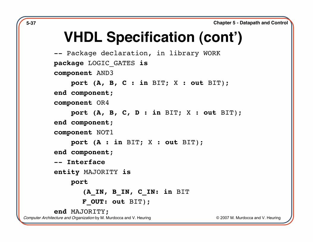
5-37 Chapter 5 - Datapath and Control
Computer Architecture and Organization by M. Murdocca and V. Heuring © 2007 M. Murdocca and V. Heuring
VHDL Specification (cont’)-- Package declaration, in library WORKpackage LOGIC_GATES iscomponent AND3 port (A, B, C : in BIT; X : out BIT);end component;component OR4 port (A, B, C, D : in BIT; X : out BIT);end component;component NOT1 port (A : in BIT; X : out BIT);end component;-- Interfaceentity MAJORITY is port
(A_IN, B_IN, C_IN: in BITF_OUT: out BIT);
end MAJORITY;

5-38 Chapter 5 - Datapath and Control
Computer Architecture and Organization by M. Murdocca and V. Heuring © 2007 M. Murdocca and V. Heuring
VHDL Specification (cont’)-- Body-- Uses components declared in package LOGIC_GATES-- in the WORK library-- import all the components in WORK.LOGIC_GATESuse WORK.LOGIC_GATES.allarchitecture LOGIC_SPEC of MAJORITY is-- declare signals used internally in MAJORITYsignal A_BAR, B_BAR, C_BAR, I1, I2, I3, I4: BIT;begin-- connect the logic gatesNOT_1 : NOT1 port map (A_IN, A_BAR);NOT_2 : NOT1 port map (B_IN, B_BAR);NOT_3 : NOT1 port map (C_IN, C_BAR);AND_1 : AND3 port map (A_BAR, B_IN, C_IN, I1);AND_2 : AND3 port map (A_IN, B_BAR, C_IN, I2);AND_3 : AND3 port map (A_IN, B_IN, C_BAR, I3);AND_4 : AND3 port map (A_IN, B_IN, C_IN, I4);OR_1 : OR3 port map (I1, I2, I3, I4, F_OUT);end LOGIC_SPEC;