4OI4 Engineering Design. 2 Objectives To provide an understanding of the steps involved in the...
47
4OI4 Engineering Design
-
Upload
alaina-eaton -
Category
Documents
-
view
212 -
download
0
Transcript of 4OI4 Engineering Design. 2 Objectives To provide an understanding of the steps involved in the...
4OI4Engineering Design

2
Objectives
• To provide an understanding of the steps involved in the design and prototyping of digital systems.
• To gain hands-on experience in design, simulation and implementation of digital systems.
• To familiarize with VHDL.

3
Expectations
• My expectation:– Speak up.
– Make the course as interactive as possible.
• Your expectations ?
4
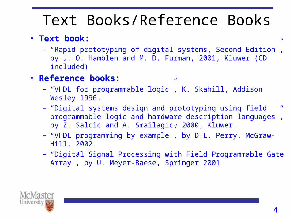
Text Books/Reference Books• Text book:
– “Rapid prototyping of digital systems, Second Edition”, by J. O. Hamblen and M. D. Furman, 2001, Kluwer (CD included)
• Reference books:– “VHDL for programmable logic”, K. Skahill, Addison Wesley 1996.
– “Digital systems design and prototyping using field programmable logic and hardware description languages”, by Z. Salcic and A. Smailagic, 2000, Kluwer.
– “VHDL programming by example”, by D.L. Perry, McGraw-Hill, 2002.
– “Digital Signal Processing with Field Programmable Gate Array”, by U. Meyer-Baese, Springer 2001
5
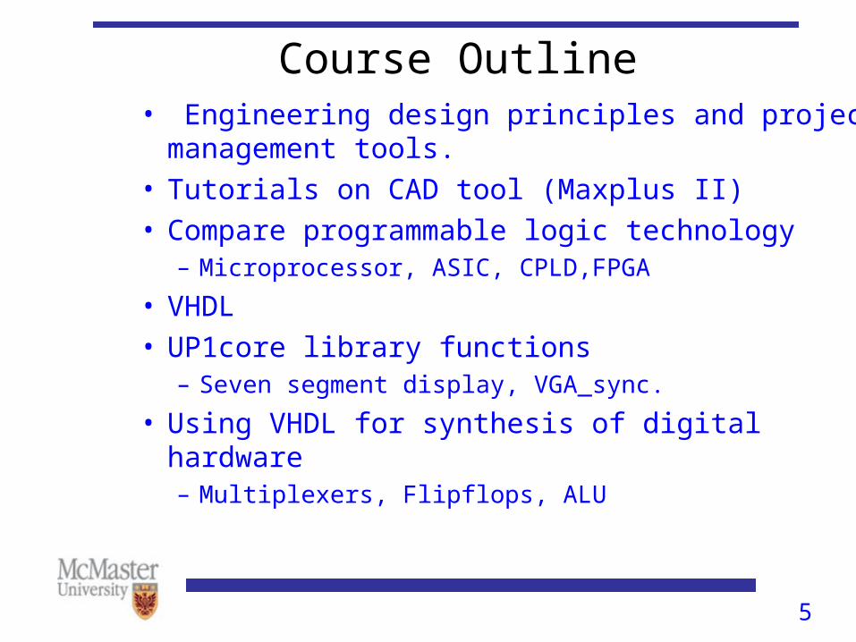
Course Outline• Engineering design principles and project management
tools.• Tutorials on CAD tool (Maxplus II)• Compare programmable logic technology
– Microprocessor, ASIC, CPLD,FPGA
• VHDL• UP1core library functions
– Seven segment display, VGA_sync.
• Using VHDL for synthesis of digital hardware– Multiplexers, Flipflops, ALU
6
Course Outline• VGA video signal – to generate a video image
using Altera UP1 board. • Keyboard and mouse interface to the Altera board.• Chapters 1,3,4,5,6,9,10 and 11 will be covered.

7
Project
• Students are supposed to complete a project in groups of two (or three)
• Every group can choose the subject of their project
• A typical project should involve the design of a digital system (e.g., FIR filter, a robot control system)
• The design should be entered into CAD tool (MAX+PLUS) using VHDL and be simulated to make sure it meets the specified requirements
• A hardware implementation of the project using the UP1 boards is required if the size of the design allows.
8
Students’ responsibilities for the project
• Form groups.• Choose a project. • Prepare a project proposal. • Work on the project.• Prepare a progress report.• Prepare a final report.
9
Lab location, time and facilities
• Lab: ITB , Room 143.• Lab hours: Mondayss and s, 2:30 to 5:30.• 8 UP1 and 2 UP2 boards in the lab.• Student can use the lab facility for their projects at
any time in the mornings and afternoons.• This is the only course using the room ITB-153.
10
CD -ROM
• Contains the MAX+PLUS II software from Altera.
• Contains the UP1core library functions(in booksoft directory)
• Contains the MAX+PLUS II manual (file Maxiigs.pdf in UG directory)
• Contains the UP1 manual (in booksoft\chap2 files univ.pdf and upds_ugs.pdf)
• Contains other useful information such as:– Application notes (from Altera) in An directory
– Application Briefs in Ab directory
– Data sheets in Ds directory
11
Project • Students are free to choose any interesting digital system.
• Perform preliminary research or literature survey.
• Design the system in VHDL and implement it on Altera UP1 or UP2 boards.
• The project should use between 10,000 and 200,000 logic gates.

12
Project Ideas • Visit the website of the text book http://users.ece.gatech.edu/~hamblen/book/book.htm• Exercises in chapters 7 to 13.• The following web page from University of Alberta has interesting projects
http://www.ece.ualberta.ca/~elliott/ee552/• Projects done in previous years
http://www.ece.mcmaster.ca/faculty/shirani/engde03/projects01.htm
http://www.ece.mcmaster.ca/faculty/shirani/engde03/projects02.htm

13
Project Ideas • Chapter 12 of the text book provides details of robot controlled by UP board. One or two groups can work on robot related projects.
• The application note (An) directory in the CD of the text book contains some interesting projects such as– ATP packet scheduler– Implementing cyclic code redundancy code checkers (CRCC)– Implementing RAM
• The application note on the Altera website has interesting projects:http://www.altera.com/literature/lit-an.html
14
List of Possible Projects • Video games implementation on UP board.• Motion estimation using FPGA• A train control system using UP board.• A robot controlled by UP board.
– IR proximity detector.– Line tracker sensor- program mail delivery robot .– Sonar ranging unit.– IR distance detector.
• Ping Pong or Frog game.• A high speed ATM switch using UP board. • Implementation of discrete cosine transform.• Neural networks.

15
Time Table• Two lab experiments – between Jan 15 and Feb 10.
The goal is to familiarize students with UP1 boards.
• By Jan 22 – Form groups of two and submit the names of project partners to the TA (Roman Kordasiewicz, [email protected]).
• By Jan 25, groups should be finalized.
• By Feb 13 – should be ready to submit project proposal and give a short presentation on the proposal.
• March 15 – Progress report ( 4 to 5 pages)

16
Time Table
• Mid April - Final presentation and report.
Forming groups
FebJan Mar April
LabProposal
ProgressReport Final report
Presentation

17
Assessment• Assignments 20 %• Proposal and Progress Report 20%
Project Proposal 8%
Proposal Presentation 5%
Progress Report 7%• Project 60%
– Final Report 15%– Presentation 5%– Project 40%
Functionally complete 20%
Design complexity 10%
Novelty 10%

18
Suggestions and requests
• Start working on the project as soon as possible
• Partition your project into modules and implement and test each module separately
• Do not take the UP boards out of the lab
• Do not play with equipment not related to this course which is in the lab
• Do not drink or eat in the lab
• Do not login on a computer and leave it idle
• If you are working late in the lab do not prop the door to the lab or to the building open
19
Contact Info• Instructor: Dr. S. Kumar• E-mail: [email protected]• Office hours: Thursday and Friday 10:00 to 1:00.• Office: CRL #204• Lab: ITB, Room 153• Lab hours: Thursday, Friday 2:30 to 5:30• TA: Roman Kordasiewicz Emails: [email protected]• Web page of the course: www.ece.mcmaster.ca/faculty/~kumars/Eng_design.htm
20
Outline• Project proposal• Engineering design process• Project management tools
– Work breakdown structure– Linear responsibility chart– Gantt chart

21
Project Proposal• Objectives : Clear and concise – up to 10 lines.• Resources:
People - Names and effective time
Facility/Equipment/Software/Funding.• Description: (4 pages maximum)
Motivation
Background and previous work
Project Details – Provide details of each milestone
and expected time for its completion.

22
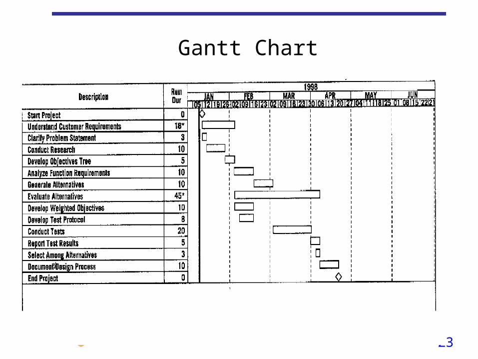
Project Proposal• Scheduling:
– Make use of Gantt Charts.
• Assumptions/Risks:
Examples: – Components may not arrive on time.– They may be too expensive.
• Deliverables:
Itemize each deliverable.• Summary: (Maximum 10 lines)
– Focus on expected end results.
23
Gantt Chart
24
Definition of Engineering Design
• The process of devising a system, component, or process to meet desired needs
25
Design Process• Example 1: Design of a juice container.
– Suppose you are in a design firm. Develop an attractive, unbreakable container for a juice maker.
• Example 2: Design of an optical fiber for Metro networks.
– Design an inexpensive optical fiber that is compatible with client’s network equipments.
• Example 3: Digital system design to fulfill the course requirement
26
Required product
Design specifications
Initial design
Simulation
Design correct?
Redesign
Prototype implementation
Testing
Meets specifications?
Finished product
Minor errors?
Make corrections
No
Yes
No
Yes
Yes
No
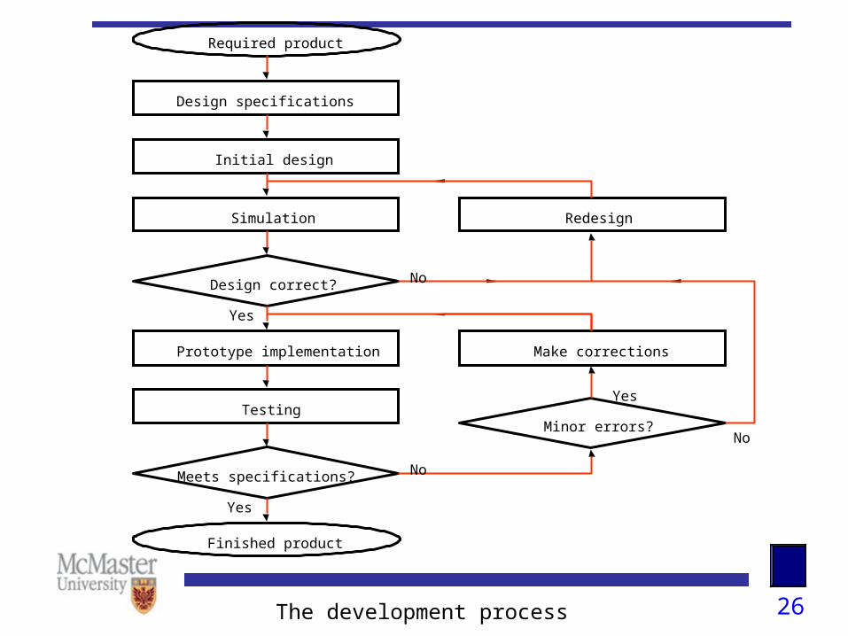
The development process

27
Design Process• Define specifications: essential features of the product are
identified.
– Specifications must be tight enough to ensure that the developed product will meet the general expectations, but not be unnecessarily constraining.

28
Design Process• Simulation: CAD tools are used to simulate the behavior of
the initial design to determine whether the obtained design meets the required specifications.
• If errors are found appropriate changes are made and verification is repeated through simulation.
• Usually all except subtle problems are discovered in this way.
• When simulation indicated that the design is correct, a prototype of the product is constructed.

29
Design Process• The prototype is thoroughly tested for conformance with the
specifications.
• Minor errors are often eliminated by making small corrections directly on the prototype.
• In the case of large errors, it is necessary to redesign the product.

30
Project Management• 3Ss of Project Management: scope, spending and
scheduling.
The project
must accomplish the goals (i.e. the design should
be successful),
must be completed within the resource limits
available,
must be done “on time”.
31
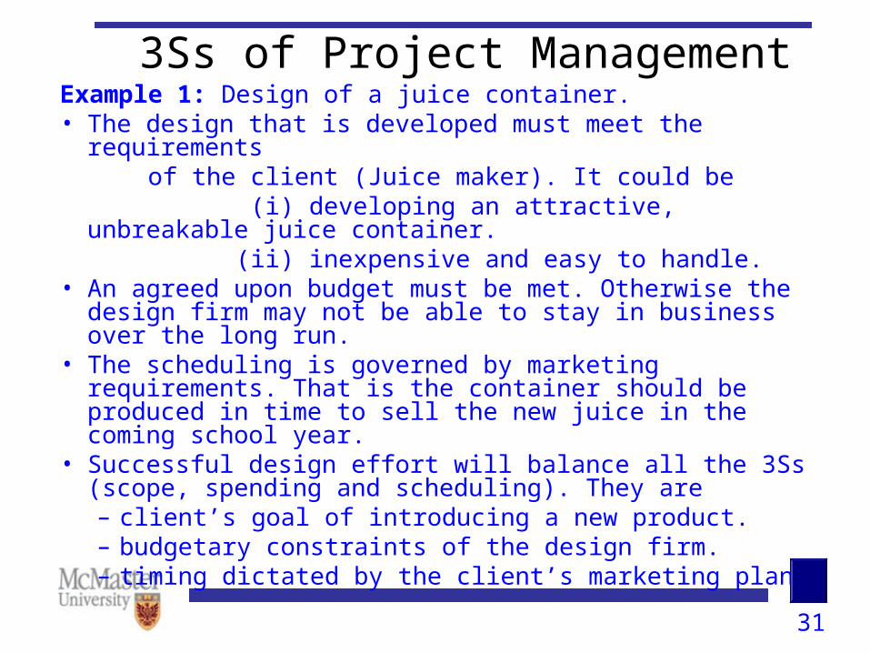
3Ss of Project ManagementExample 1: Design of a juice container.• The design that is developed must meet the requirements of the client (Juice maker). It could be (i) developing an attractive, unbreakable juice container. (ii) inexpensive and easy to handle.• An agreed upon budget must be met. Otherwise the design
firm may not be able to stay in business over the long run.• The scheduling is governed by marketing requirements. That
is the container should be produced in time to sell the new juice in the coming school year.
• Successful design effort will balance all the 3Ss (scope, spending and scheduling). They are– client’s goal of introducing a new product.– budgetary constraints of the design firm.– timing dictated by the client’s marketing plan.
32
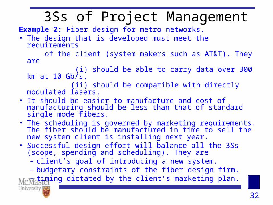
3Ss of Project ManagementExample 2: Fiber design for metro networks.• The design that is developed must meet the requirements of the client (system makers such as AT&T). They are (i) should be able to carry data over 300 km at 10 Gb/s. (ii) should be compatible with directly modulated lasers.• It should be easier to manufacture and cost of manufacturing
should be less than that of standard single mode fibers.• The scheduling is governed by marketing requirements. The
fiber should be manufactured in time to sell the new system client is installing next year.
• Successful design effort will balance all the 3Ss (scope, spending and scheduling). They are– client’s goal of introducing a new system.– budgetary constraints of the fiber design firm.– timing dictated by the client’s marketing plan.

33
3Ss of Project Management
Example 3: Student design to fulfill the course requirement.
• The design should be successful.
• The cost of hardware components should not exceed $X. Otherwise the department will not reimburse the cost.
• The scheduling is governed by the timing of the course (In our case it is April second week).

34
Project Management Tools: Work Breakdown Structure (WBS)
• WBS is the breakdown of the task into several subtasks. In our example of juice container design, at the top level, we could have the following subtasks:
– Understand customer requirements.
– Generate and list all the possible designs.
– Select among designs.– Document the design process.

35
Work Breakdown Structure (WBS)
Design a juicecontainer
Select among
designs
Understand customer
requirements
Generate and evaluate designs.
DocumentDesign process
Research consumerneeds
Research priordesigns
List all possibledesigns
Brainstorm ideas
Develop weights forobjectives & apply
Make initialselection
Review withclient
Draft finalreport
Review withclient
Final report

36
Work Breakdown Structure (WBS)
Design fiber forMetro networks
Test the designby doing lab expt.
Understand client’s
requirements
Generate and evaluate designs.
Do a field trialwith the client
Research client’sneeds
Research priordesigns
List all possibledesigns
Brainstorm ideas
Develop weights forobjectives & apply
Coordinate betweenexperimentalist and
fiber maker.
Review withclient
Coordinate Between in-house
Experimentalist andclient
Final report

37
Work Breakdown Structure (WBS)
• WBS is – Not an organization chart for completing a project.– Not a flow chart showing logical relationship
among tasks.– Not a listing of all the disciplines or skills required
to complete a task.– a break down of task, not of roles or people in an
organization.

38
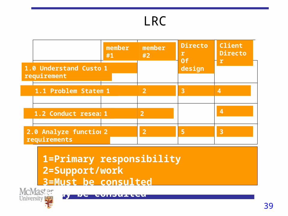
Project Management Tools: Linear Responsibility Chart (LRC)
• The design team has to decide who will take responsibility for each task. This is achieved by building linear responsibility chart (LRC).
• LRC is a very important document translating “what” of the WBS into “who” of responsibility.
• In LRC, the rows show the tasks and subtasks and the columns show the team member names. Roles of each participant for a particular task is shown in the intersection.
• Team leader need not always have the primary responsibility for every task.
• LRC can be used to let stakeholders in a project understand what they are expected to do.
39
LRC
1.0 Understand Custom.requirement
member #1
member #2
Director Of design
Client Director
1
2 43 1.1 Problem Statement 1
1=Primary responsibility 2=Support/work3=Must be consulted 4=May be consulted5=Review 6=Final approval
1.2 Conduct research 1 2 4
2.0 Analyze function requirements
2 2 5 3
40
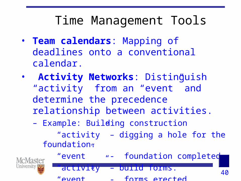
Time Management Tools
• Team calendars: Mapping of deadlines onto a conventional calendar.
• Activity Networks: Distinguish “activity” from an “event” and determine the precedence relationship between activities.– Example: Building construction
“activity” – digging a hole for the foundation.
“event” - foundation completed.
“activity” – build forms.
“event” - forms erected.

41
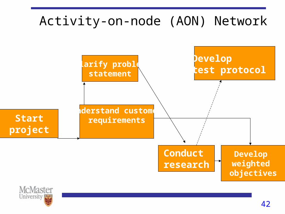
Time Management Tools: Activity Networks
• Represent an “activity” with a node and identify “event” with an arc that extends from a node.
• You can switch – i.e. “activity” is an arc and “event” is a node.
• Most of the project management software use “activity on node” convention called as AON networks.
• Activity network provides the logical relationships between various activities.
42
Activity-on-node (AON) Network
Startproject
Clarify problemstatement
Understand customer
requirements
Conduct research
Developtest protocol
Develop weighted objectives

43
Time Management Tools: Activity Networks
• Suppose the team is busy during some time interval, but idle during some other time. Some tasks can be delayed for the “idle” period. But some tasks can not be delayed.
• An activity for which we can delay the start time is said to have “slack”.
• “slack” is the time difference between the earliest date we can start that activity and the latest date on which we can start it without affecting the overall timing of the project.

44
Time Management Tools: Activity Networks
• Activities that have no slack are said to be on critical path .
• Identifying critical path and completion of activities on critical path is of central importance to the success of a project.
45
Time Management Tools: Gantt Chart
• The information incorporated into activity network can be displayed as a bar graph called as “Gantt chart”.
• This approach to scheduling is originated from Henry Gantt.
• For each activity, there is a start date and an end date that can be read from the time axis.

46
Gantt Chart
47
Summary
• Project proposal
• Engineering Design
• Project Management tools– WBS
– LRC
– Activity networks
– Gantt-charts