4K HDMI IP Video Wall Controller, IPVDS-500-ED User Manual manual IPVDS-500-ED V1.3... · 4K HDMI...
52
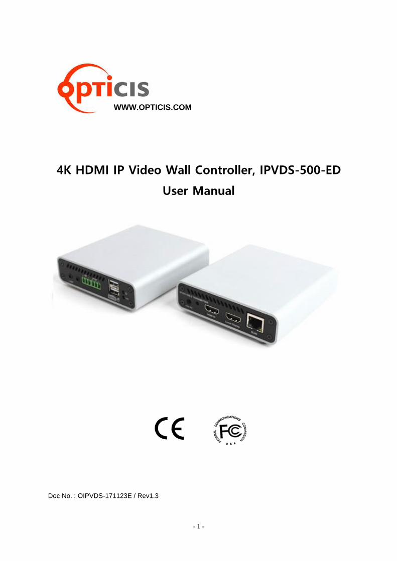
- 1 - 4K HDMI IP Video Wall Controller, IPVDS-500-ED User Manual Doc No. : OIPVDS-171123E / Rev1.3 WWW.OPTICIS.COM
Transcript of 4K HDMI IP Video Wall Controller, IPVDS-500-ED User Manual manual IPVDS-500-ED V1.3... · 4K HDMI...
- 1 -
4K HDMI IP Video Wall Controller, IPVDS-500-ED
User Manual
Doc No. : OIPVDS-171123E / Rev1.3
WWW.OPTICIS.COM

- 2 -
Table of contents
1. Product Description ..................................................................................................4
1.1 Main Features ....................................................................................................5
1.2 Supporting Video Resolution for Input/Output .........................................5
2. Shipping Group ..........................................................................................................6
3. System Requirement .................................................................................................7
4. Exterior Description ...................................................................................................8
5. Installation ..................................................................................................................9
5.1 Hardware Installation Procedure ...................................................................9
5.2 Reset and Factory Reset ................................................................................10
5.3 PC Program Installation ................................................................................10
6. Start IPVDS-500-ED .................................................................................................11
6.1 Log-in ................................................................................................................11
6.2 Menu Contents ................................................................................................12
6.2.1 Application Icon Menu ........................................................................12
6.2.2 Ribbon Menu .........................................................................................12
6.3 Layout Management ......................................................................................16
6.3.1 Layout Editing ........................................................................................17
Zoom in/out
Audio Setup
6.3.2 Preset Save .............................................................................................19
6.4 Display Placement ..........................................................................................21
6.4.1 Display Layout Edit ...............................................................................22
Display Rotation
OSD
7. Context Menu ...........................................................................................................27

- 3 -
7.1 Layout Management Context Menu ...........................................................27
7.1.1 Encoder List Context Menu …....……………………………….………….27
Device Setup
Firmware Update
Set Source Name
Encoder Crop Feature
7.1.2 Video Wall Context Menu…………………………………………………...31
Remove Encoder
Split Merged Cell
Add Black Mask
Bring/Send Layer
Set Location Name
Delete Location Name
7.2 Display Placement Context Menu ...............................................................35
7.2.1 Decoder List Context Menu ................................................................35
Device Setup
Firmware Update
7.2.2 Video Wall Context Menu ...................................................................36
Remove Decoder
Decoder Layout Setup(Display Setup)
Bezel/Resolution/Stretch Type
8. Additional Feature ...................................................................................................39
8.1 Scheduling Feature .........................................................................................39
8.2 Multiple Video Wall ........................................................................................42
8.3 Plug-in Feature ................................................................................................46
9. Product Specification ..............................................................................................47
10. Troubleshooting .....................................................................................................48
11. Warranty ..................................................................................................................50

- 4 -
1. Product Description
IPVDS-500-ED, 4K HDMI IP Video Wall Controller, is an integrated control solution that plays
multi-source of audio/video (such as PC, Media player, DVD, or Blu-ray) on the video wall system
and multiple individual displays simutaneously.
This solution offers advanced video/audio matrix feature as well as control of video wall system
which divide high quality video source(4K30Hz or 1080p60Hz) into multiple video walls with using
IPVDS-500-E(encoder) and IPVDS-500-D(decoder) on IP network. IPVDS-500 enables convenient
system configuration and control for AV system integrator and installer, and cost-efficiency
compared to complicated matrix system. For these reasons, solution using IPVDS-500-ED provides
optimal soltion not only to large video wall system like control room, security, traffic control
system, but also to general venues like conference room, classroom, presentation room, and
worship service.
Program provided for system control offers preview function for source devices, and various
display configuration like merging, overlaying, clearing of displays on the layout management
with allocating audio/video sources with drag and drop operation of mouse.
Figure 1. Connection Diagram

- 5 -
1.1 Main Features
- TCP/IP based IP network: Gigabit Ethernet
- Up to 4K resolution (3840x2160 at 30Hz) or 1080p at 60Hz.
- Up to 256 displays (16x16, 4x64, 1x256 and etc) Video wall and multi-source support
- Supports analog/HDMI audio input and output
- Fast switching time / Low video latency
- Transmit HDMI/DVI video, USB, RS-232, Audio, DIO signal vid IP network
- Provides HDMI loop-thru port for Local display
- Provides merge, overlay and split features on Layout Management
- Support preset mode for user defined layout (save/load)
- Provides scheduling action with preset function (sequential/weekly mode)
- M:N virtual matrix supported
- Provides mounting bracket (model: OPSCB): VESA 75,100 standard (optional)
- Provides 1U rack, 4 in 1 rack & Power rack, PR5V-16: 16* 5V output (optional)
IPVDS-500 Control PC Application
- PC application for controlling Video wall and individual displays
- Provides drag and drop operation for host allocation and preview
- Provide allocate, merge, split, overlay function on Layout Management
- Provides preview screen before applying it to actual displays
- Provide total of 99 pre-sets for user defined layout (save/load)
- Provides pre-set scheduling function in Sequential (dwell time based) / Weekly mode (hourly/weekly based)
- Bezel compensation in 0.1mm unit
Figure 2. PC Application
- Application
Control Room / Traffic Control System / Security and Education / Digital Signage / Pro AV Field
1.2 Supporting Video Resolution for Input / Output
1) Supports HDMI 1.4, 3840x2160p/24/25/30Hz
2) Supports HDMI 1.4/HDTV, 1920x1080p60Hz
3) Supports VESA digital, 1920x1200p60Hz

- 6 -
2. Shipping Group
□ IPVDS-500-ED □ Power Adapter □ HDMI cable 1.2m □ Mini-USB cable □ User Manual
2.1 General Specification
- IPVDS-500-E: TX (Encoder) or IPVDS-500-D: RX (Decoder)
- AC / DC power adaptor: One (1) unit of 5V / 2A
- One (1) HDMI male to male cable (1.2m)
- One (1) Mini-USB Cable for PC
- User manual
2.2 Optional Specification
- RS-232 cable: DB-9 male to 3pin terminal block
- Mounting bracket (OPSCB) complying with VESA 75, 100 standard
- 1U rack (4 in 1 rack) and power rack (PR5V-16, 16*5V output)
- 7 -
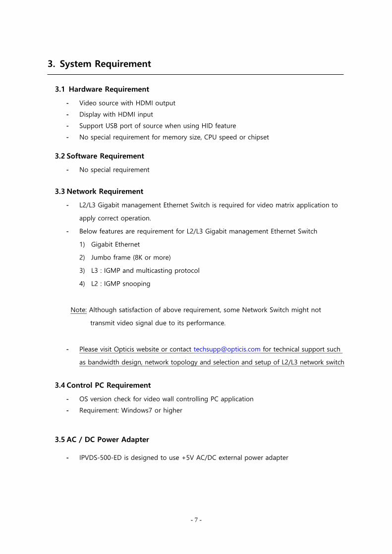
3. System Requirement
3.1 Hardware Requirement
- Video source with HDMI output
- Display with HDMI input
- Support USB port of source when using HID feature
- No special requirement for memory size, CPU speed or chipset
3.2 Software Requirement
- No special requirement
3.3 Network Requirement
- L2/L3 Gigabit management Ethernet Switch is required for video matrix application to
apply correct operation.
- Below features are requirement for L2/L3 Gigabit management Ethernet Switch
1) Gigabit Ethernet
2) Jumbo frame (8K or more)
3) L3 : IGMP and multicasting protocol
4) L2 : IGMP snooping
Note: Although satisfaction of above requirement, some Network Switch might not
transmit video signal due to its performance.
- Please visit Opticis website or contact [email protected] for technical support such
as bandwidth design, network topology and selection and setup of L2/L3 network switch
3.4 Control PC Requirement
- OS version check for video wall controlling PC application
- Requirement: Windows7 or higher
3.5 AC / DC Power Adapter
- IPVDS-500-ED is designed to use +5V AC/DC external power adapter

- 8 -
4. Exterior Description
4.1 IPVDS-500-E, Encoder
Figure. 3 Encoder Front Panel Figure. 4 Encoder Back Panel
USB IN : Connection with PC USB port for use of keyboard and mouse(HID)
L-IN : Line input port. Connection with line out audio
DIO / RS-232 : Optional
USB A: Connection of Keyboard / Mouse. (support F/W Upgrade)
Power Jack(5V, 3.5mm) : 5V DC power input
Reset : Reset button. (Factory reset when pressing more than 5 seconds)
HDMI IN (Source) : Video source input
Local Display (Monitor) : HDMI output for the local display
RJ-45 (LAN) : Connection with RJ-45 network cable (CAT5e / CAT6)
L/R/C Switch : TBD
4.2 IPVDS-500-D, Decoder
Figure. 5 Decoder Front Panel Figure. 6 Decoder Back Panel
L-OUT : Audio Line out port
DIO / RS-232 : Optional
Dual USB A : Connection of remote Keyboard / Mouse (F/W Upgrade support)
Power Jack(5V, 3.5mm) : 5V DC power input
Reset : Reset button. (Factory reset when pressing more than 5 seconds)
HDMI OUT : HDMI output for the display
RJ-45 (LAN) : Connection with RJ-45 network cable (CAT5e / CAT6)
Note1: If replacement of video source is needed, power reset of both encoder and decoder is
required as re-connecting +5V power adapter.

- 9 -
4.3 LED Indication
IPVDS-500-ED indicates power and network status with 2 LED on the front panel.
- Power status LED (RED)
‘Blinking’ Booting, Initializing status
‘ON’ Completion of booting, working status
- Link LED (Green)
‘Blinking’ Ready to work with network connection, waiting for source status
‘ON’ Connection with network link (encoder and decoder)
‘OFF’ Disconnection with network link (encoder and decoder)
5. Installation
5.1 Hardware Installation Procedure
Important: Please follow below procedure. If not installed properly, it can suffer malfunction.
Step 1
Unpack the package.
Step 2
Turn on Source, Display, Network Switch (L2/L3).
Step 3
Turn on the PC for Video Wall control application and connect LAN cable (CAT5e / CAT6)
to network switch.
Step 4
Connect HDMI cable from display source to HDMI IN port of IPVDS-500-E (TX).
Step 5 (Optional)
Connect supplied USB cable in IPVDS-500-E (TX) to USB port in PC.
This step can be skipped if you don’t need local/remote control of keyboard and mouse.
Step 6 (Optional)
Connect HDMI cable from display output of HDMI monitor to IPVDS-500-E (TX).
Step 7
Connect LAN cable (CAT5e/6) from IPVDS-500-E (Tx) TO RJ45 port of network switch.
- 10 -
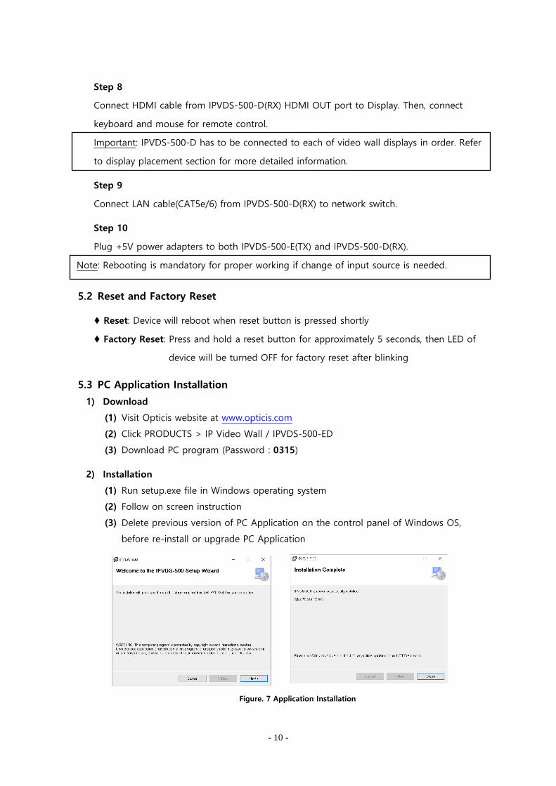
Step 8
Connect HDMI cable from IPVDS-500-D(RX) HDMI OUT port to Display. Then, connect
keyboard and mouse for remote control.
Important: IPVDS-500-D has to be connected to each of video wall displays in order. Refer
to display placement section for more detailed information.
Step 9
Connect LAN cable(CAT5e/6) from IPVDS-500-D(RX) to network switch.
Step 10
Plug +5V power adapters to both IPVDS-500-E(TX) and IPVDS-500-D(RX).
Note: Rebooting is mandatory for proper working if change of input source is needed.
5.2 Reset and Factory Reset
♦ Reset: Device will reboot when reset button is pressed shortly
♦ Factory Reset: Press and hold a reset button for approximately 5 seconds, then LED of
device will be turned OFF for factory reset after blinking
5.3 PC Application Installation
1) Download
(1) Visit Opticis website at www.opticis.com
(2) Click PRODUCTS > IP Video Wall / IPVDS-500-ED
(3) Download PC program (Password : 0315)
2) Installation
(1) Run setup.exe file in Windows operating system
(2) Follow on screen instruction
(3) Delete previous version of PC Application on the control panel of Windows OS,
before re-install or upgrade PC Application
Figure. 7 Application Installation

- 11 -
6. Start Video Wall
IPVDS-500 allows convenient use of its features with IPVDS-500 Video Wall control PC Application.
User can merge, split, overlay and clear video source for Video Wall by dragging & dropping the
mouse for host allocation. Not only that user can also check and confirm preview screen on the
layout management before applying it to the display.
6.1 Log-in
(1) Run IPVDS-500 PC Application
(2) Insert Password & confirm password for administrator (ID: admin) when first-time
log-in
(3) Log-in with admin ID and its password
(4) To log-in with different ID, restart the PC App. or click Log-out button
Figure. 8 Log-in Screen
Note: After launching PC App, it will automatically search for the device and have you log-in
when it is done with searching.
- 12 -
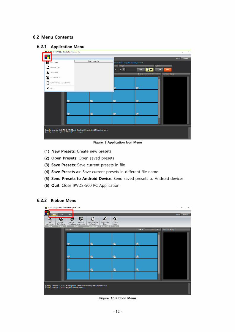
6.2 Menu Contents
6.2.1 Application Menu
Figure. 9 Application Icon Menu
(1) New Presets: Create new presets
(2) Open Presets: Open saved presets
(3) Save Presets: Save current presets in file
(4) Save Presets as: Save current presets in different file name
(5) Send Presets to Android Device: Send saved presets to Android devices
(6) Quit: Close IPVDS-500 PC Application
6.2.2 Ribbon Menu
Figure. 10 Ribbon Menu
- 13 -
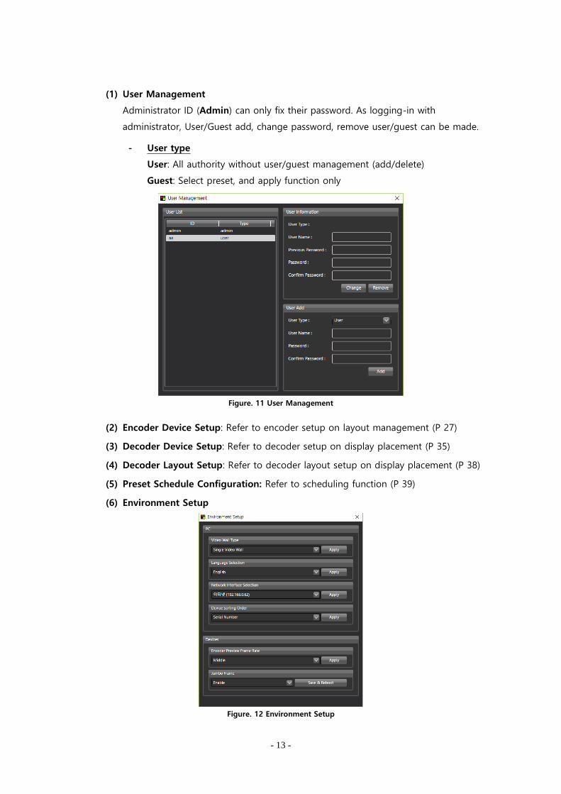
(1) User Management
Administrator ID (Admin) can only fix their password. As logging-in with
administrator, User/Guest add, change password, remove user/guest can be made.
- User type
User: All authority without user/guest management (add/delete)
Guest: Select preset, and apply function only
Figure. 11 User Management
(2) Encoder Device Setup: Refer to encoder setup on layout management (P 27)
(3) Decoder Device Setup: Refer to decoder setup on display placement (P 35)
(4) Decoder Layout Setup: Refer to decoder layout setup on display placement (P 38)
(5) Preset Schedule Configuration: Refer to scheduling function (P 39)
(6) Environment Setup
Figure. 12 Environment Setup

- 14 -
Video Wall Type
Select ‘Single Video Wall’ (Default) or ‘Multiple Video Wall’ (Pro)
In order to use Pro version, license key is required.
To obtain license key, contact [email protected] or [email protected]
Figure. 13 Pro Version License
Language
Select ‘English’ or ‘Korean’
Network Interface Selection
If there are more than one network interface for the Control PC that IPVDS-500
PC App has installed, problem can be occurred when searching or operating.
Appointing correct network interface can solve this problem.
Device Sorting Order
Appoint sorting order of searched devices.
When decoder is automatically sorted, it will be placed automatically as its order,
default setup is ‘serial number’.
Encoder Preview Frame Rate
Change preview frame rate in ‘Low/Mid/High’
Users who want to use KVM function in priority, has to select it as ‘Low’ as
preview frame rate is related to HID (Keyboard & Mouse) function.
Jumbo Frame
This option decides MTU size, and video quality will be affective when disabled.
‘Enabled’ 8000 byte
‘Disabled’ 1500 byte
(7) Firmware Update
Step 1
Run Firmware Update.

- 15 -
Step 2
Select ‘All Decoders’, ‘All Encoders’ or specific device need to be updated.
Note: Change IP address and Gateway from control panel, if IP address and gateway of PC and
desired device don’t match.
Step 3
Click Browse button, and open particular firmware file to update.
Note: User can check firmware version of selected device from right space.
Step 4
Click ‘Upload’ button, and make sure power adapter is connected firmly.
LED will flash while updating and device will automatically reboot when update is done.
Note: Pop-up message will appear when update is done. (approximately 5 minutes)
Figure. 14 Firmware Update Window
Note : Firmware update with USB flash drive
Step 1: Save firmware file (IPVDS-500-X-xxxxxx.tgz) in USB flash drive.
Step 2: Insert USB flash drive in USB port of IPVDS-500 device.
Step 3: Plug-in +5V power adapter.
Step 4: While booting, device will search for the firmware file which has saved in USB
flash drive, and it will start updating if file exist in USB flash drive.
Step 5: While updating, LED will be blink, and it will reboot when update is completed.
Update will take approximately 5 minutes and make sure power adapter is
not disconnected during update.
(8) View: Adjust size of device list, layout, and log record on IPVDS-500 PC application.
(9) Help: Check version of IPVDS-500 PC application

- 16 -
6.3 Layout Management
Figure. 15 Layout Management
Encoder List
- Search: Search IPVDS-500-ED on the network
- Encoder device list that is connected to the IP network
- Check preview scene of Video sources connected
- Assign preview screen for Video Wall layout with drag and drop
Video Wall
- Assign encoder devices, edit layout for video wall in rows and columns
- Audio ON/OFF
Display Placement
- Change display layout, move to setup page for decoder assign and change
Preset
- Save current edited video wall layout
- Load layout that had saved previously
- Start preset scheduling button ( )
Actions
- Clear button will empty all the encoder that has assigned in video wall region
- Apply button will apply current video wall setup, which can be check on
preview screen, to the video wall and individual displays
- 17 -
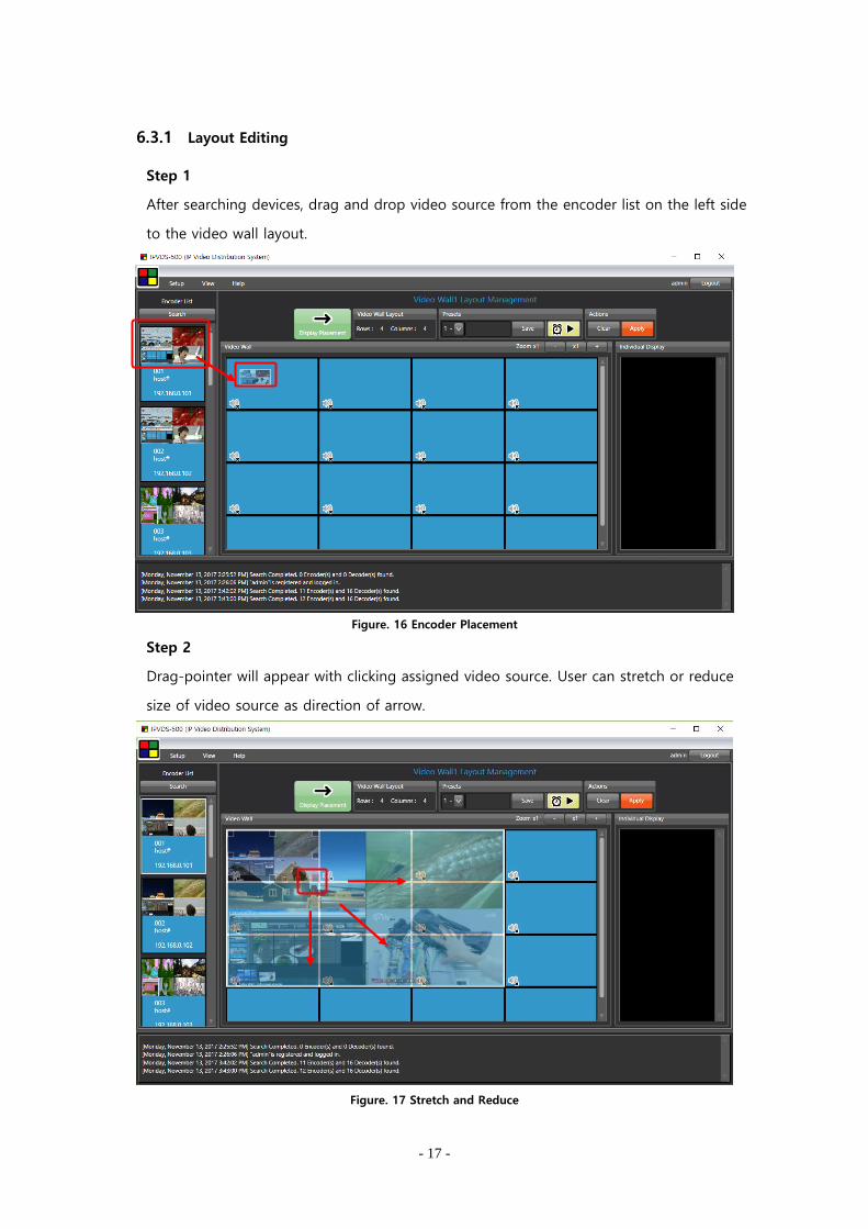
6.3.1 Layout Editing
Step 1
After searching devices, drag and drop video source from the encoder list on the left side
to the video wall layout.
Figure. 16 Encoder Placement
Step 2
Drag-pointer will appear with clicking assigned video source. User can stretch or reduce
size of video source as direction of arrow.
Figure. 17 Stretch and Reduce
- 18 -
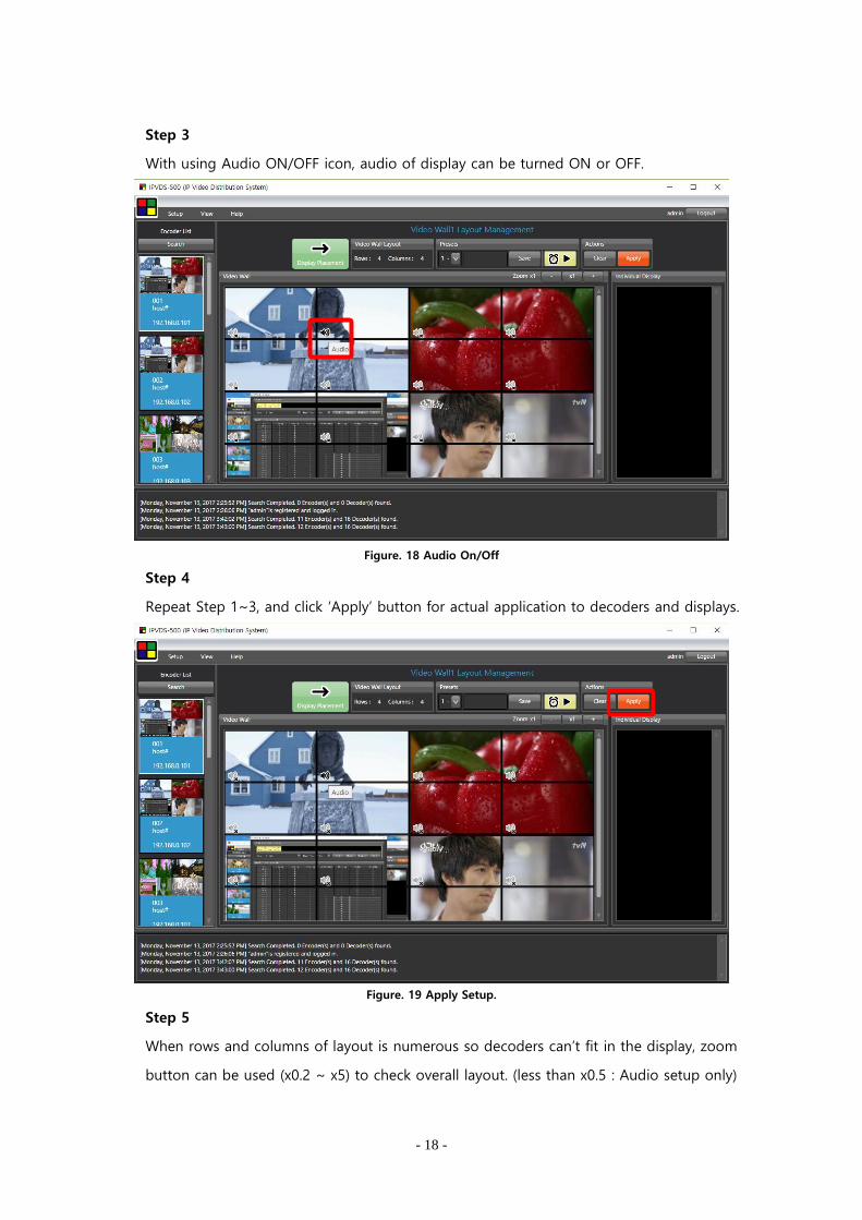
Step 3
With using Audio ON/OFF icon, audio of display can be turned ON or OFF.
Figure. 18 Audio On/Off
Step 4
Repeat Step 1~3, and click ‘Apply’ button for actual application to decoders and displays.
Figure. 19 Apply Setup.
Step 5
When rows and columns of layout is numerous so decoders can’t fit in the display, zoom
button can be used (x0.2 ~ x5) to check overall layout. (less than x0.5 : Audio setup only)

- 19 -
6.3.2 Preset Save
Step 1
Type name of current preset, and click ‘Save’ button to save current display placement.
Figure. 20 Preset Save
Step 2
If select non-saved preset number, video wall placement will be initialized, and it will
become editable status. Place sources and save as Step 1.
Presets can be saved up to 99.
Figure. 21 Change Preset
Clear

- 20 -
Step 3
As selecting particular preset number, user can load saved video wall layout.
Click ‘Apply’ button to have current preset to decoder devices and displays.
Figure. 22 Apply Setup
Step 4
When user re-launch IPVDS-500 application, last saved preset will be loaded if user
save preset setup with ‘Save Presets’ from icon menu.
Figure. 23 Save Preset File
- 21 -
6.4 Display Placement
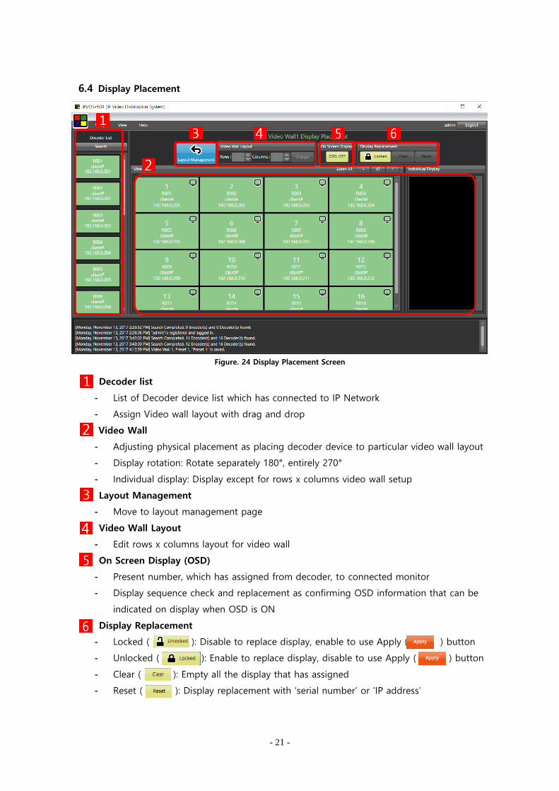
Figure. 24 Display Placement Screen
Decoder list
- List of Decoder device list which has connected to IP Network
- Assign Video wall layout with drag and drop
Video Wall
- Adjusting physical placement as placing decoder device to particular video wall layout
- Display rotation: Rotate separately 180°, entirely 270°
- Individual display: Display except for rows x columns video wall setup
Layout Management
- Move to layout management page
Video Wall Layout
- Edit rows x columns layout for video wall
On Screen Display (OSD)
- Present number, which has assigned from decoder, to connected monitor
- Display sequence check and replacement as confirming OSD information that can be
indicated on display when OSD is ON
Display Replacement
- Locked ( ): Disable to replace display, enable to use Apply ( ) button
- Unlocked ( ): Enable to replace display, disable to use Apply ( ) button
- Clear ( b ): Empty all the display that has assigned
- Reset ( ): Display replacement with ‘serial number’ or ‘IP address’

- 22 -
6.4.1 Edit Display Layout
Step 1
Change display layout to desired rows and columns (Default: 4x4)
Figure. 25 Change Video Wall Layout
Step 2
Replace decoder placement to desired place with drag and drop when ‘unlocked’
Figure. 26 Change Decoder Placement

- 23 -
Assigned decoder can be removed separately or entirely with mouse right click, and listed
decoder under search button can be place with drag and drop.
Figure. 27 Remove Decoder
‘Clear’ button will empty all decoder which has assigned to layout, and ‘Reset’ button will
automatically place decoders with ‘serial number’ or ‘IP address’ as environment setup.
Figure. 28 Display Replacement
Sequence of automatic placement
Drag & Drop

- 24 -
Step 3
With clicking Display rotation button on upper right hand corner, display will be rotated
clockwise. One click will rotate 180°, and one more click will rotate 270°.
180°: For separate display. Display will rotate 180°
270°: For entire display. Entire display on the layout will rotate 270°
Monitor need to be rotated 90° for normal screen output
Figure. 29 Separate Display – 180° Clockwise Rotation
Figure. 30 Entire Display – 270° Clockwise Rotation
- 25 -
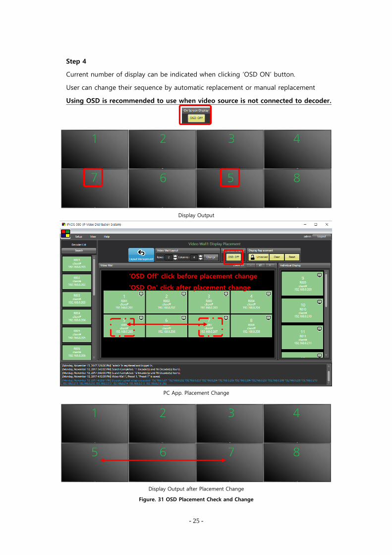
Step 4
Current number of display can be indicated when clicking ‘OSD ON’ button.
User can change their sequence by automatic replacement or manual replacement
Using OSD is recommended to use when video source is not connected to decoder.
Display Output
PC App. Placement Change
Display Output after Placement Change
Figure. 31 OSD Placement Check and Change
‘OSD Off’ click before placement change
‘OSD On’ click after placement change

- 26 -
Step 5
Display placement is disabled when it is Display replacement is ‘Locked’
‘Layout management’ button will lead user to main screen for layout management.
Figure. 32 Layout Locked
Step 6
When coming back to layout management page after changing display placement,
following window will pop up. If click no, change from display placement will not be
applied. If click yes, change will be applied
Step 7
After Step 6, decoder placement and connection is done. Check 6.3 Layout Management
and connect video sources.

- 27 -
7. Context Menu
7.1 Layout Management Context Menu
7.1.1 Encoder List Context Menu
Figure. 33 Layout Management Context Menu
(1) Device setup.
a) Network information setup
DHCP IP(dynamic) / STATIC IP(static)
Device name : Set the name of encoder device
English (No Korean), Special symbol(+,-,_,#), maximum 20 character
Will be applied after save and restart.
Figure. 34 Encoder Device Setup – Network Management
- 28 -
b) Bitrate Setup
Transmission speed : Image quality and network condition
50/100/150/200(Default)/Best [Mbps]
It is recommended to set all encoders have same Bitrate
Apply Save & Reboot
Figure. 35 Encoder Device Setup – Bitrate Setup
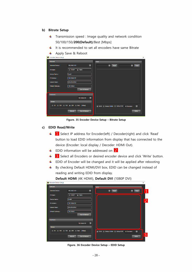
c) EDID Read/Write
Select IP address for Encoder(left) / Decoder(right) and click ‘Read’
button to load EDID information from display that has connected to the
device (Encoder: local display / Decoder: HDMI Out).
EDID information will be addressed on
Select all Encoders or desired encoder device and click ‘Write’ button.
EDID of Encoder will be changed and it will be applied after rebooting
By checking Default HDMI/DVI box, EDID can be changed instead of
reading and writing EDID from display.
Default HDMI (4K HDMI), Default DVI (1080P DVI)
Figure. 36 Encoder Device Setup – EDID Setup

- 29 -
(2) Firmware Update
6.2.2 Refer to Ribbon menu (7) Firmware update (page 14).
(3) Source Name Setup
Set the video source name
English, Korean, Special symbol, maximum 20 characters
Source name will be appeared on the upper right corner of each display
Figure. 37 Source Name Setup
(4) Source Name Remove / All Source Name Remove
Remove source name separately, or entirely
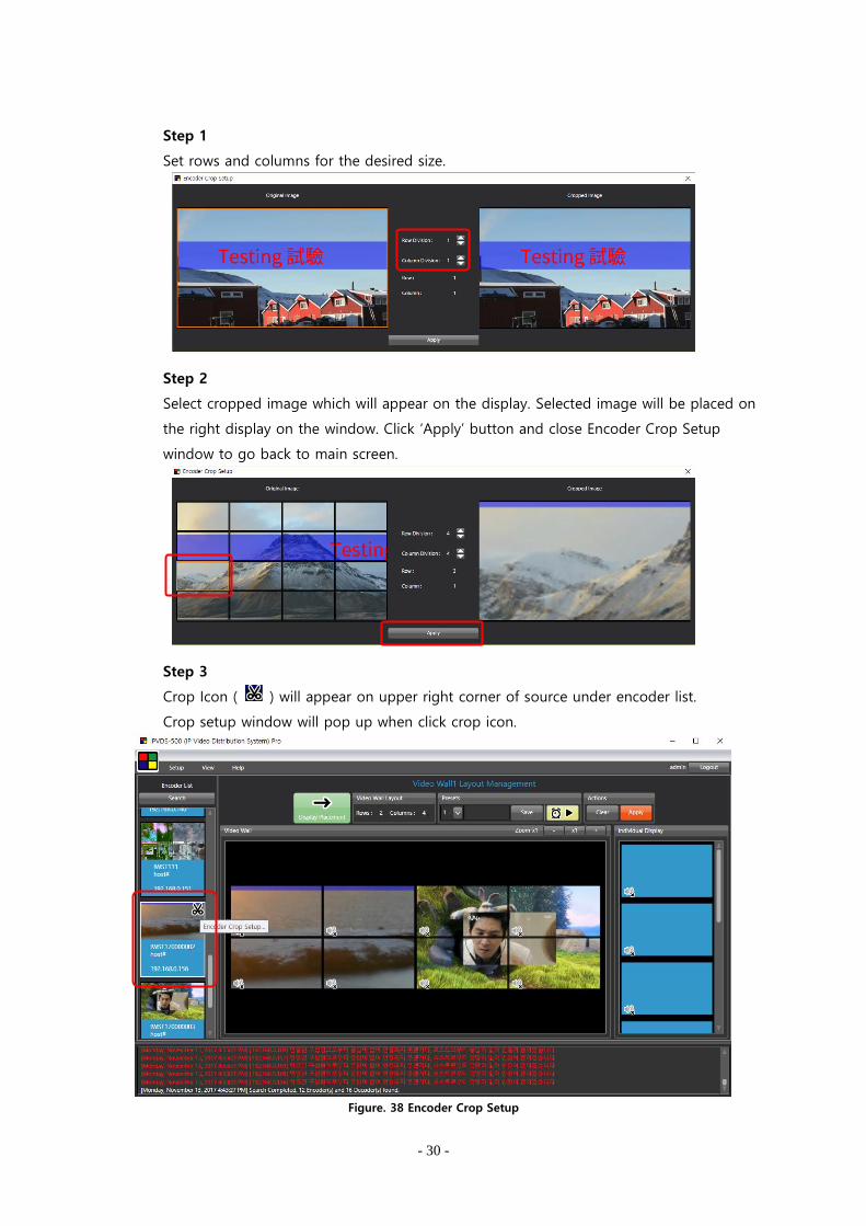
(5) Encoder Crop Setup
Crop an image in rows and columns (max 256, 16x16 ~ 4x64 ~ 1x256) and select
Transmit selected image from display source
Note 1. Crop setup requires IPVDS-500 Pro version update to use.
Note 2. Crop setup will not apply to local display.
- 30 -
Step 1
Set rows and columns for the desired size.
Step 2
Select cropped image which will appear on the display. Selected image will be placed on
the right display on the window. Click ‘Apply’ button and close Encoder Crop Setup
window to go back to main screen.
Step 3
Crop Icon ( ) will appear on upper right corner of source under encoder list.
Crop setup window will pop up when click crop icon.
Figure. 38 Encoder Crop Setup
- 31 -
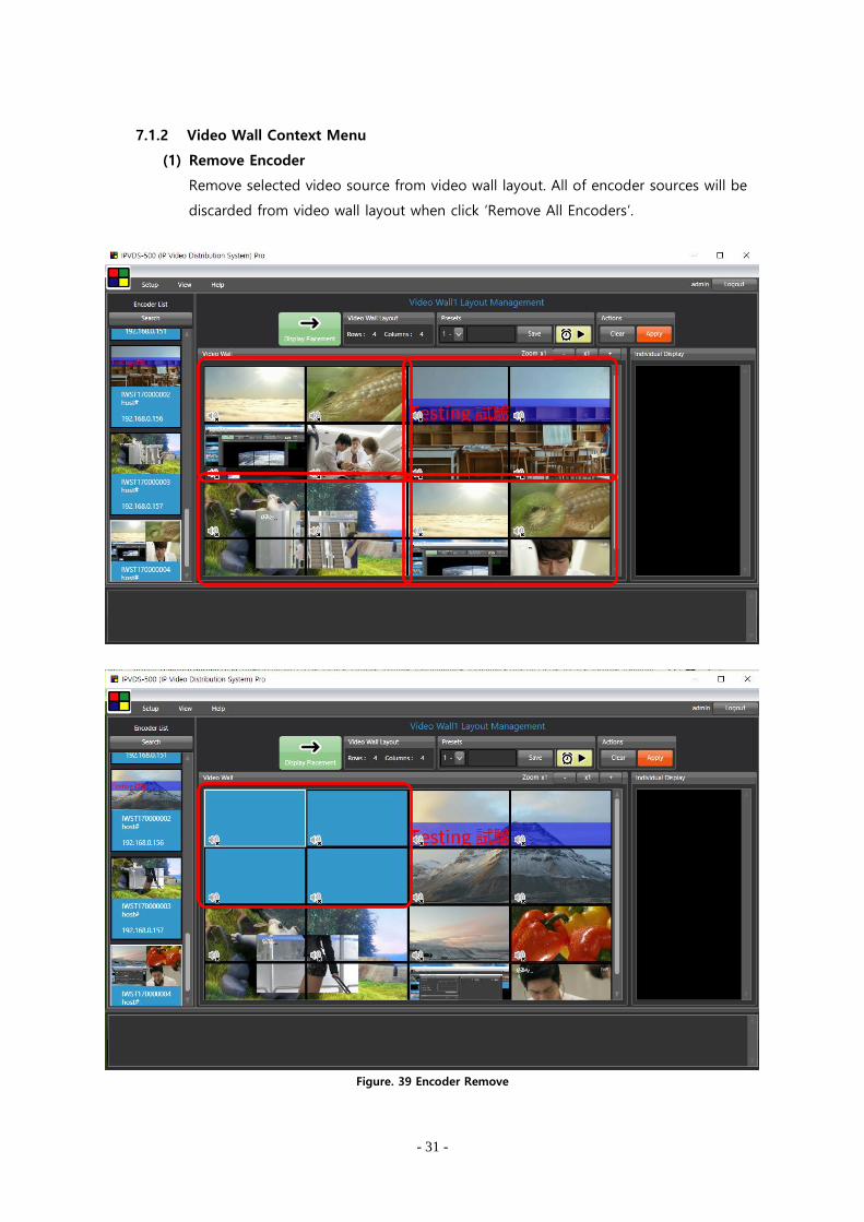
7.1.2 Video Wall Context Menu
(1) Remove Encoder
Remove selected video source from video wall layout. All of encoder sources will be
discarded from video wall layout when click ‘Remove All Encoders’.
Figure. 39 Encoder Remove

- 32 -
(2) Split Merged Cells
Change stretched video wall source (M x N) to 1 x 1 video source.
After change, 1 x 1 video source will be placed on upper left corner of existing cells.
Figure. 40 M x N Merge
Figure. 41 Split Merged Cell

- 33 -
(3) Add Black Mask
Replace selected cell to black mask.
When applied, selected display will switch over to black-out state.
Black mask can be removed with ‘Encoder Remove’ button.
Figure. 42 Add Black Mask
(4) Bring/Send Layer
Bring and send overlaid layer to front and/or back.
Foremost source will appear on the display.
Figure. 43 Layer Overlay
Source #1
Source #2
Overlay
- 34 -
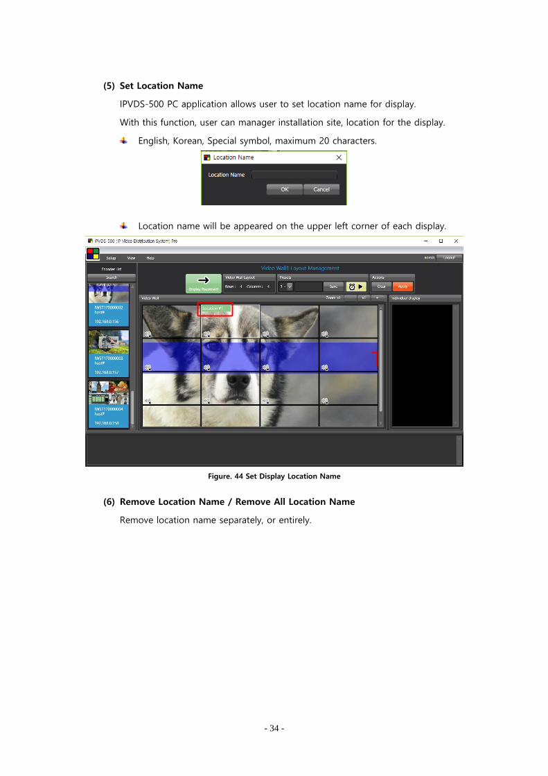
(5) Set Location Name
IPVDS-500 PC application allows user to set location name for display.
With this function, user can manager installation site, location for the display.
English, Korean, Special symbol, maximum 20 characters.
Location name will be appeared on the upper left corner of each display.
Figure. 44 Set Display Location Name
(6) Remove Location Name / Remove All Location Name
Remove location name separately, or entirely.

- 35 -
7.2 Display Placement Context Menu
7.2.1 Decoder List Context Menu
Figure. 45 Display Placement Context Menu
(1) Device Setup
a) Network Information Setup
DHCP IP(dynamic) / STATIC IP(static)
Device name : set decoder device name
English (no Korean), Special symbol (+,-,_,#), Maximum 20 characters
Will be applied after save and restart
Figure. 46 Decoder Device Setup – Network Setup
b) Restart
Restart of selected or entire decoder
(2) Firmware Update
6.2.2 Refer to Ribbon menu (7) Firmware update (page 14).
- 36 -
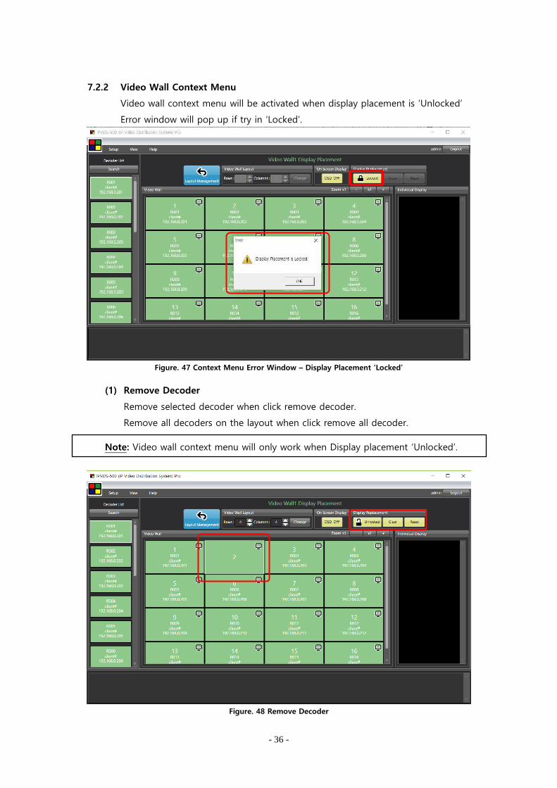
7.2.2 Video Wall Context Menu
Video wall context menu will be activated when display placement is ‘Unlocked’
Error window will pop up if try in ‘Locked’.
Figure. 47 Context Menu Error Window – Display Placement ‘Locked’
(1) Remove Decoder
Remove selected decoder when click remove decoder.
Remove all decoders on the layout when click remove all decoder.
Note: Video wall context menu will only work when Display placement ‘Unlocked’.
Figure. 48 Remove Decoder
- 37 -
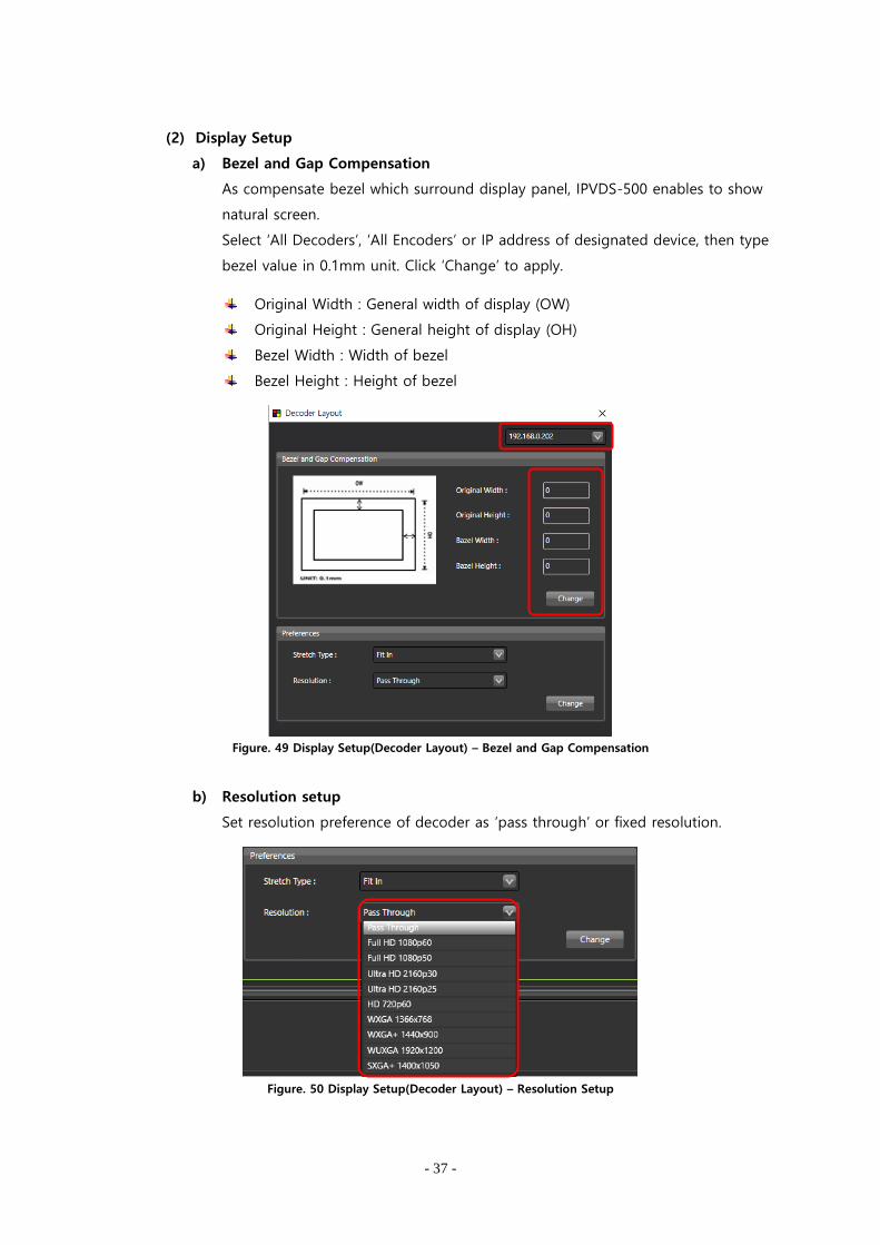
(2) Display Setup
a) Bezel and Gap Compensation
As compensate bezel which surround display panel, IPVDS-500 enables to show
natural screen.
Select ‘All Decoders’, ‘All Encoders’ or IP address of designated device, then type
bezel value in 0.1mm unit. Click ‘Change’ to apply.
Original Width : General width of display (OW)
Original Height : General height of display (OH)
Bezel Width : Width of bezel
Bezel Height : Height of bezel
Figure. 49 Display Setup(Decoder Layout) – Bezel and Gap Compensation
b) Resolution setup
Set resolution preference of decoder as ‘pass through’ or fixed resolution.
Figure. 50 Display Setup(Decoder Layout) – Resolution Setup

- 38 -
c) Display Fit in/Stretch out
Use ‘Fit it’ and ‘Stretch out’ feature for atypical ratio on decoder layout setup.
‘Fit in’ : Reduce or increase size of original source to fit in to the display
‘Stretch out’ : Maintain original ratio as cutting video source to the display
Figure. 51 Placing Video Source to 1 Row 2 Columns
Original Video Source
‘Fit In’ Setup – Display Source Fit into the Display
‘Stretch Out’ Setup – Cut Out of Bottom Part of Display Source
Figure. 52 Display Output Screen
- 39 -
8. Additional features
8.1 Scheduling feature
IPVDS-500 can automatically operate as saved preset schedule. There are two different
preset schedule options; Sequence Preset Schedule, Weekly Preset Schedule.
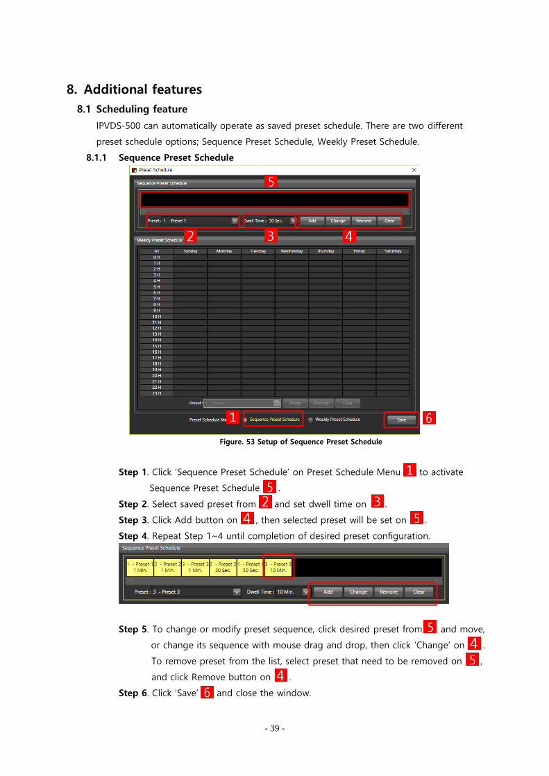
8.1.1 Sequence Preset Schedule
Figure. 53 Setup of Sequence Preset Schedule
Step 1. Click ‘Sequence Preset Schedule’ on Preset Schedule Menu to activate
Sequence Preset Schedule .
Step 2. Select saved preset from and set dwell time on .
Step 3. Click Add button on , then selected preset will be set on .
Step 4. Repeat Step 1~4 until completion of desired preset configuration.
Step 5. To change or modify preset sequence, click desired preset from and move,
or change its sequence with mouse drag and drop, then click ‘Change’ on .
To remove preset from the list, select preset that need to be removed on ,
and click Remove button on .
Step 6. Click ‘Save’ and close the window.

- 40 -
8.1.2 Weekly Preset Schedule
Figure. 54 Weekly Preset Schedule
Step 1. Click ‘Weekly Preset Schedule’ on Preset Schedule Menu to activate
Weekly Preset Schedule.
Step 2. Click designated time schedule or drag and select region on .
Step 3. Select saved preset from .
Step 4. Click ‘Assign’ button on to assign selected preset on that region.
Step 5. To change or modify, click ‘Unassign’ on to empty selected region, or click
‘Clear’ to empty the entire region.
Step 6. Repeat Step 2~4 to make desired weekly schedule and click ‘Save’ and
close the window.

- 41 -
8.1.3 Operate Scheduling
Once ‘Sequence Schedule’ or ‘Weekly Schedule’ setup is done, user can operate
scheduling feature with ‘Start Preset Scheduling’ button on layout management.
Figure. 55 Start Preset Scheduling
Once Preset Scheduling is activated, ‘Start Preset Scheduling’ icon will be changed,
And click ‘Stop Preset Scheduling’ icon( ) to deactivate.
Note: All other function is disabled when using Preset Scheduling.
Important: Control PC has to be connected to the network to use Preset Scheduling.
- 42 -
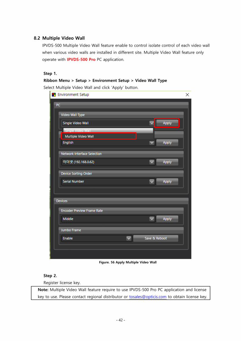
8.2 Multiple Video Wall
IPVDS-500 Multiple Video Wall feature enable to control isolate control of each video wall
when various video walls are installed in different site. Multiple Video Wall feature only
operate with IPVDS-500 Pro PC application.
Step 1.
Ribbon Menu > Setup > Environment Setup > Video Wall Type
Select Multiple Video Wall and click ‘Apply’ button.
Figure. 56 Apply Multiple Video Wall
Step 2.
Register license key.
Note: Multiple Video Wall feature require to use IPVDS-500 Pro PC application and license
key to use. Please contact regional distributor or [email protected] to obtain license key.

- 43 -
Step 3.
Now, IPVDS-500 PC application will be changed to IPVDS-500 Pro, and user can select
and set different video wall on .
Figure. 57 Pro Version Start-Up Page
Step 4.
Click ‘Configure’ button to load device assignment window. Click ‘Search’ button to
load all the encoder and decoder device on the network.
Figure. 58 Device Assignment Window
- 44 -
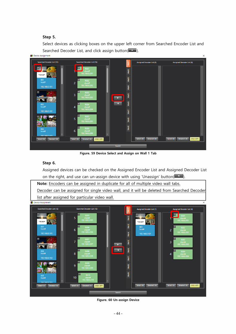
Step 5.
Select devices as clicking boxes on the upper left corner from Searched Encoder List and
Searched Decoder List, and click assign button( ).
Figure. 59 Device Select and Assign on Wall 1 Tab
Step 6.
Assigned devices can be checked on the Assigned Encoder List and Assigned Decoder List
on the right, and use can un-assign device with using ‘Unassign’ button( ).
Note: Encoders can be assigned in duplicate for all of multiple video wall tabs.
Decoder can be assigned for single video wall, and it will be deleted from Searched Decoder
list after assigned for particular video wall.
Figure. 60 Un-assign Device
- 45 -
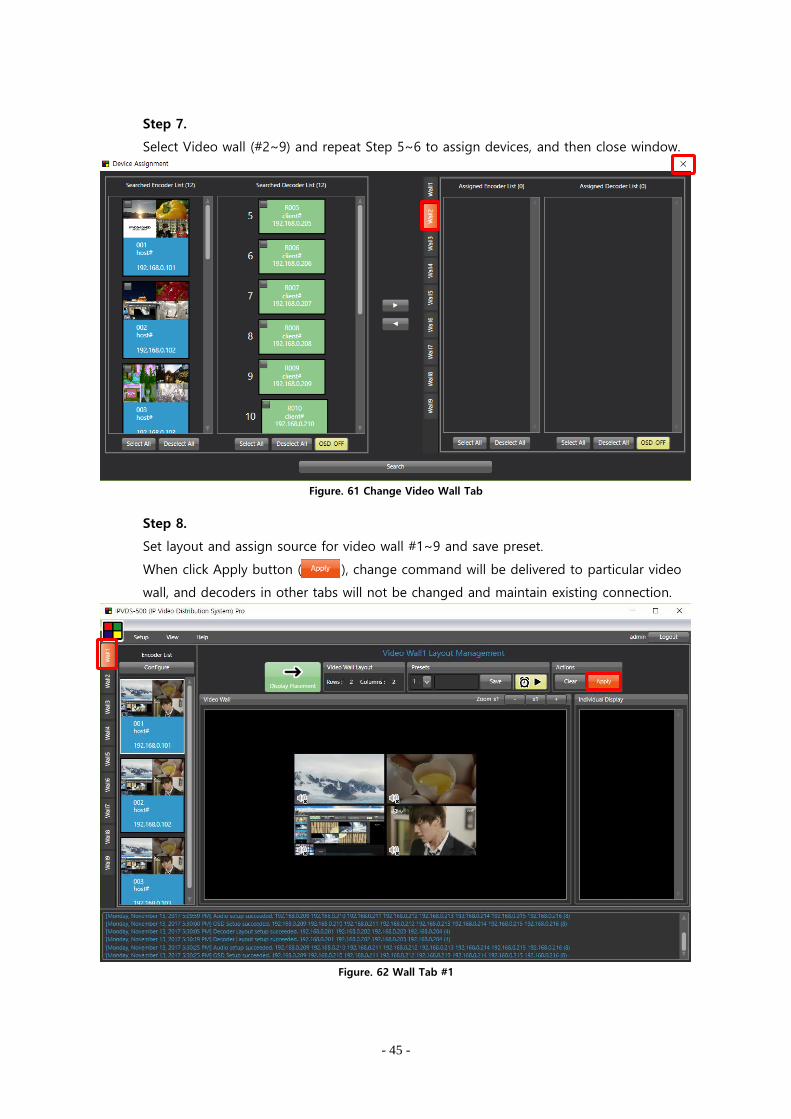
Step 7.
Select Video wall (#2~9) and repeat Step 5~6 to assign devices, and then close window.
Figure. 61 Change Video Wall Tab
Step 8.
Set layout and assign source for video wall #1~9 and save preset.
When click Apply button ( ), change command will be delivered to particular video
wall, and decoders in other tabs will not be changed and maintain existing connection.
Figure. 62 Wall Tab #1
- 46 -
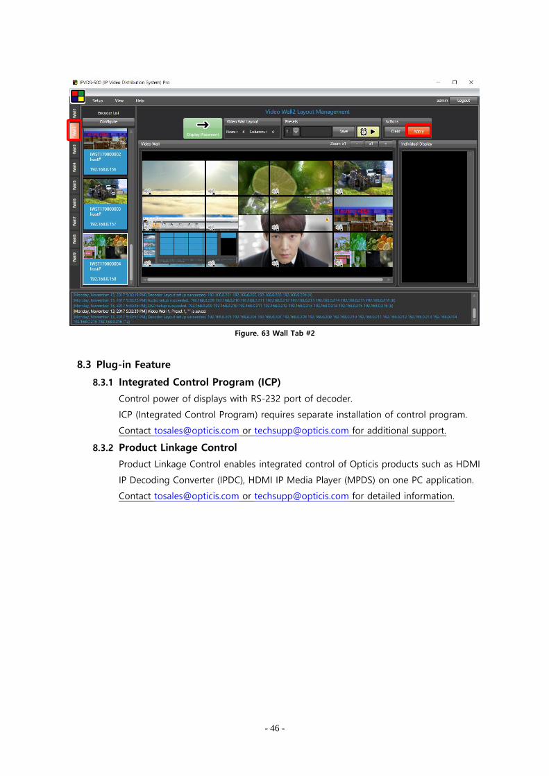
Figure. 63 Wall Tab #2
8.3 Plug-in Feature
8.3.1 Integrated Control Program (ICP)
Control power of displays with RS-232 port of decoder.
ICP (Integrated Control Program) requires separate installation of control program.
Contact [email protected] or [email protected] for additional support.
8.3.2 Product Linkage Control
Product Linkage Control enables integrated control of Opticis products such as HDMI
IP Decoding Converter (IPDC), HDMI IP Media Player (MPDS) on one PC application.
Contact [email protected] or [email protected] for detailed information.
- 47 -
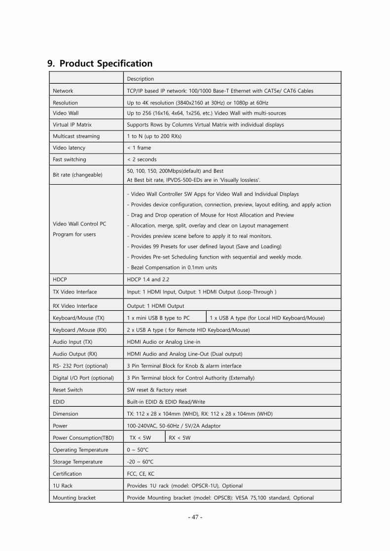
9. Product Specification
Description
Network TCP/IP based IP network: 100/1000 Base-T Ethernet with CAT5e/ CAT6 Cables
Resolution Up to 4K resolution (3840x2160 at 30Hz) or 1080p at 60Hz
Video Wall Up to 256 (16x16, 4x64, 1x256, etc.) Video Wall with multi-sources
Virtual IP Matrix Supports Rows by Columns Virtual Matrix with individual displays
Multicast streaming 1 to N (up to 200 RXs)
Video latency < 1 frame
Fast switching < 2 seconds
Bit rate (changeable) 50, 100, 150, 200Mbps(default) and Best
At Best bit rate, IPVDS-500-EDs are in ‘Visually lossless’.
Video Wall Control PC
Program for users
- Video Wall Controller SW Apps for Video Wall and Individual Displays
- Provides device configuration, connection, preview, layout editing, and apply action
- Drag and Drop operation of Mouse for Host Allocation and Preview
- Allocation, merge, split, overlay and clear on Layout management
- Provides preview scene before to apply it to real monitors.
- Provides 99 Presets for user defined layout (Save and Loading)
- Provides Pre-set Scheduling function with sequential and weekly mode.
- Bezel Compensation in 0.1mm units
HDCP HDCP 1.4 and 2.2
TX Video Interface Input: 1 HDMI Input, Output: 1 HDMI Output (Loop-Through )
RX Video Interface Output: 1 HDMI Output
Keyboard/Mouse (TX) 1 x mini USB B type to PC 1 x USB A type (for Local HID Keyboard/Mouse)
Keyboard /Mouse (RX) 2 x USB A type ( for Remote HID Keyboard/Mouse)
Audio Input (TX) HDMI Audio or Analog Line-in
Audio Output (RX) HDMI Audio and Analog Line-Out (Dual output)
RS- 232 Port (optional) 3 Pin Terminal Block for Knob & alarm interface
Digital I/O Port (optional) 3 Pin Terminal block for Control Authority (Externally)
Reset Switch SW reset & Factory reset
EDID Built-in EDID & EDID Read/Write
Dimension TX: 112 x 28 x 104mm (WHD), RX: 112 x 28 x 104mm (WHD)
Power 100-240VAC, 50-60Hz / 5V/2A Adaptor
Power Consumption(TBD) TX < 5W RX < 5W
Operating Temperature 0 ~ 50°C
Storage Temperature -20 ~ 60°C
Certification FCC, CE, KC
1U Rack Provides 1U rack (model: OPSCR-1U), Optional
Mounting bracket Provide Mounting bracket (model: OPSCB): VESA 75,100 standard, Optional
- 48 -
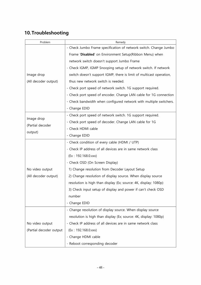
10. Troubleshooting
Problem Remedy
Image drop
(All decoder output)
- Check Jumbo Frame specification of network switch. Change Jumbo
Frame ‘Disabled’ on Environment Setup(Ribbon Menu) when
network switch doesn’t support Jumbo Frame
- Check IGMP, IGMP Snooping setup of network switch. If network
switch doesn’t support IGMP, there is limit of multicast operation,
thus new network switch is needed.
- Check port speed of network switch. 1G support required.
- Check port speed of encoder. Change LAN cable for 1G connection
- Check bandwidth when configured network with multiple switchers.
- Change EDID
Image drop
(Partial decoder
output)
- Check port speed of network switch. 1G support required.
- Check port speed of decoder. Change LAN cable for 1G
- Check HDMI cable
- Change EDID
No video output
(All decoder output)
- Check condition of every cable (HDMI / UTP)
- Check IP address of all devices are in same network class
(Ex : 192.168.0.xxx)
- Check OSD (On Screen Display)
1) Change resolution from Decoder Layout Setup
2) Change resolution of display source. When display source
resolution is high than display (Ex; source: 4K, display: 1080p)
3) Check input setup of display and power if can’t check OSD
number
- Change EDID
No video output
(Partial decoder output
- Change resolution of display source. When display source
resolution is high than display (Ex; source: 4K, display: 1080p)
- Check IP address of all devices are in same network class
(Ex : 192.168.0.xxx)
- Change HDMI cable
- Reboot corresponding decoder
- 49 -
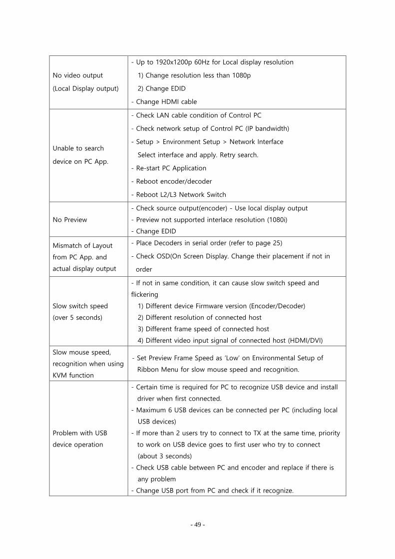
No video output
(Local Display output)
- Up to 1920x1200p 60Hz for Local display resolution
1) Change resolution less than 1080p
2) Change EDID
- Change HDMI cable
Unable to search
device on PC App.
- Check LAN cable condition of Control PC
- Check network setup of Control PC (IP bandwidth)
- Setup > Environment Setup > Network Interface
Select interface and apply. Retry search.
- Re-start PC Application
- Reboot encoder/decoder
- Reboot L2/L3 Network Switch
No Preview
- Check source output(encoder) - Use local display output
- Preview not supported interlace resolution (1080i)
- Change EDID
Mismatch of Layout
from PC App. and
actual display output
- Place Decoders in serial order (refer to page 25)
- Check OSD(On Screen Display. Change their placement if not in
order
Slow switch speed
(over 5 seconds)
- If not in same condition, it can cause slow switch speed and
flickering
1) Different device Firmware version (Encoder/Decoder)
2) Different resolution of connected host
3) Different frame speed of connected host
4) Different video input signal of connected host (HDMI/DVI)
Slow mouse speed,
recognition when using
KVM function
- Set Preview Frame Speed as ‘Low’ on Environmental Setup of
Ribbon Menu for slow mouse speed and recognition.
Problem with USB
device operation
- Certain time is required for PC to recognize USB device and install
driver when first connected.
- Maximum 6 USB devices can be connected per PC (including local
USB devices)
- If more than 2 users try to connect to TX at the same time, priority
to work on USB device goes to first user who try to connect
(about 3 seconds)
- Check USB cable between PC and encoder and replace if there is
any problem
- Change USB port from PC and check if it recognize.

- 50 -
11. Warranty
1 (One) Year Warranty
Opticis warrants IPVDS-500-ED, HDMI IP Video Wall controller to be free from defects in
workmanship and material, under normal use and service, for a period of one(1) year from the
date of purchase from Opticis or authorized resellers.
To request repair or service from Opticis, customer shall not open the product, nor place any part
of IPVDS-500 without assistance from Opticis. Keep serial number sticker on the device.
Opticis has no responsibility for any software, firmware, information or memory data of customer
contained in, stored on, or integrated with any returned to Opticis for repair
(Under warranty or not)
1. Free Repair
- Faulty IPVDS-500 under normal use in warranty in period
2. Customer Paid Repair
- Faulty IPVDS-500 but out of warranty period
- Faulty caused by negligence and/or intention of customer
- Faulty caused by voluntary alternation or repair without approval from Opticis
- Faulty caused by natural calamities
- Faulty caused by connection with other faulty device
If a product does not work as warranted during applicable warranty period, Opticis shall, at its
option and expense, repair the defective product or part, deliver to customer an equivalent
product or part to replace the defective item refund to purchase price for the defective product.
All products that are replaced will become the property of Opticis. Replacement products may be
new or reconditioned.
Dispose of Old Electrical & Electronic Equipment
(Applicable in the European Union and other European countries with separate systems)
- 51 -
This symbol on the product or on its packaging indicates that this product shall not be
treated as household waste. Instead it shall be handed over to the applicable
collection point for the recycling of electrical and electronic equipment. By ensuring
this product is disposed of correctly, you will help prevent potential negative
consequences for the environment and human health, which could otherwise be
caused by inappropriate waste handling of this product.
The recycling of materials will help to conserve natural resources. For more detailed information about
recycling of this product, please contact your local city office, your household waste disposal service
or the shop where you purchased the product.

- 52 -
Please visit Opticis website, www.opticis.com
or contact [email protected] or [email protected]
if you need any technical support or additional support.
Opticis Headquater
7F SPG Dream Building
166, Jeongjail-ro,
Bundang-gu,
Seongnam-si, Gyeonggi-do, 13558
Tel: +82 (31) 719-8033 Fax: +82 (31) 719-8032