4G Lte DT Optim Planning Atoll
71
LOGO 1 Alfin Hikmaturokhman.,ST.,MT
description
4G LTE DT
Transcript of 4G Lte DT Optim Planning Atoll

LOGO
1Alfin Hikmaturokhman.,ST.,MT

LOGO
RF Planning Tools
Asset AircommNetact Tornado Planet Ev / Mentum PlanetAtollU-netTCP (Tems Cell Planner)ZXPOS CNS
Alfin Hikmaturokhman,MT 2

LOGO
RF Planning Tools
Alfin Hikmaturokhman,MT 3

LOGO
Training Program
• Atoll Overview
• Modelling Lte Network in Atoll
• Step by Step to Start the Lte Atoll Project
• Make Coverage Prediction
• Prediction Analysis
• Neighbour Planning
• PCI Planning
• Capacity Planning
Alfin Hikmaturokhman,MT 4

LOGO
Atoll General Concepts Multi-technology tool
2G (GSM/GPRS/EDGE), 3G (W-CDMA/UMTS HSPA, CDMA2000 1xRTT 1xEV-DO, TD-SCDMA), 4G (LTE), WiMAX 802.16d and 802.16e, microwave links
Open, scalable and flexible architecture
Largest third-party product offering available on the market Dynamic simulators, propagation models, etc.
Ergonomic and user-friendly GUI Windows-based tool Copy/paste and export/import of radio/geo data in/from standard applications
Flexibility in data management Display, sorts, filters
Slide 5 of 61Alfin Hikmaturokhman,MT

LOGO
LTE Workflow in AtollLTE Workflow in AtollOpen an existing project or create a new
one
Prediction study reports
Traffic maps
Network configuration- Add network elements- Change parameters
User-defined values
Automatic or manual neighbour allocation
Basic predictions(Best server, signal level)
Monte-Carlo simulations
Signal quality and throughput predictions
Cell load conditions
Subscriber lists
And/or
Frequency plan analysis
Automatic or manual frequency planning
Automatic or manual physical cell ID planning
6Alfin Hikmaturokhman,MT

LOGO
Atoll ProjectAs in any RF tool, the following information is needed to create a project in Atoll.Geodata FDD or TDDSpectrum: frequency band and channel bandwidthPropagation ModelSite, Cell, Transmitter info Bearer infoOther LTE Parameters
Alfin Hikmaturokhman,MT 7

LOGO
Launch Atool & User Interface
8Alfin Hikmaturokhman,MT

LOGOGet Started
9Alfin Hikmaturokhman,MT

LOGO
Alfin Hikmaturokhman,MT 10

LOGO Setting Project Area
11Alfin Hikmaturokhman,MT

LOGOImport Map
12Alfin Hikmaturokhman,MT

LOGOImport Raster Map
Generally the following data maps need to be imported in Atoll: heights (map of the altitude above sea level), clutter classes (type of land used) and vectors (vector maps). The import order is optional.
Generally the following data maps need to be imported in Atoll: heights (map of the altitude above sea level), clutter classes (type of land used) and vectors (vector maps). The import order is optional.
13Alfin Hikmaturokhman,MT

LOGO
Import Clutter DataClick File->Import, open the index.txt file for clutter data, select Clutter Classes, click OK.
14Alfin Hikmaturokhman,MT

LOGO
Import DTM DataClick File->Import, open the index.txt file for DTM data, select Altitudes, click OK.
15Alfin Hikmaturokhman,MT

LOGOContd..
Vector index ->VectorsVector index ->Vectors
16Alfin Hikmaturokhman,MT

LOGO
Antenna Patterns Antenna patterns can be imported into Atoll, or manually added.
17Alfin Hikmaturokhman,MT

LOGO Set Antenna
18Alfin Hikmaturokhman,MT

LOGO
Horizontal and Vertical Patern
Alfin Hikmaturokhman,MT 19

LOGO
Input Lte PARAMETER
Alfin Hikmaturokhman,MT 20
LOGO
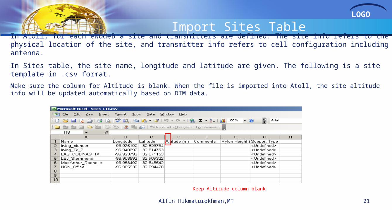
Import Sites TableIn Atoll, for each eNodeB a site and transmitters are defined. The site info refers to the physical location of the site, and transmitter info refers to cell configuration including antenna.
In Sites table, the site name, longitude and latitude are given. The following is a site template in .csv format.
Make sure the column for Altitude is blank. When the file is imported into Atoll, the site altitude info will be updated automatically based on DTM data.
Keep Altitude column blank
21Alfin Hikmaturokhman,MT
LOGO
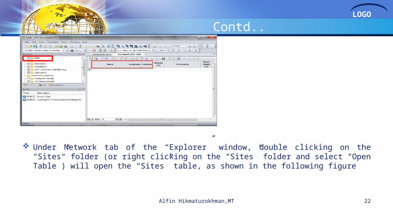
Contd..
Under Network tab of the “Explorer” window, double clicking on the “Sites” folder (or right clicking on the “Sites” folder and select “Open Table”) will open the “Sites” table, as shown in the following figure
Alfin Hikmaturokhman,MT 22

LOGO
Contd..
Alfin Hikmaturokhman,MT 23

LOGOTransmitters parameters setting
Double click on the “Transmitters” folder in Network tab (or right click on “Transmitters” and select “Open Table”) to open the “Transmitters” table, as shown in the following figure.
Alfin Hikmaturokhman,MT 24

LOGO
Contd..
Alfin Hikmaturokhman,MT 25

LOGO
Contd..
Alfin Hikmaturokhman,MT 26

LOGO
Add new sites The steps for importing the network data into Atoll have been introduced above. Atoll also
provides another method to add new sites directly in the Map Window.
Atoll adds the corresponding information into the data sheets
Alfin Hikmaturokhman,MT 27
LOGO
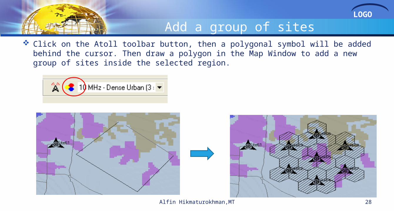
Add a group of sites Click on the Atoll toolbar button, then a polygonal symbol will be added behind the cursor. Then
draw a polygon in the Map Window to add a new group of sites inside the selected region.
Alfin Hikmaturokhman,MT 28

LOGOSet the propagation model for each transmitter
Open the “Transmitters” tab and select the propagation model in pull-down menu of the “Main propagation model” field
Alfin Hikmaturokhman,MT 29

LOGO
Atoll integrates many propagation models including Okuruma-Hata, Cost-Hata, SPM (Standard Propagation Model), ITU370, ITU526, ITU 529, Longley-Rice, Erceg-Greenstein (SUI), Sakagami Extended (3.5 GHz) and WLL models.
Alfin Hikmaturokhman,MT 30

LOGO
Contd.. If all transmitters use the same propagation model, then the quickest way is to
define the model in the “Transmitters properties” dialog box. In the “Propagation” tab, select the propagation model.
Alfin Hikmaturokhman,MT 31

LOGO
Frequency Bands setting
Under Parameters tab, click ->Network Settings-> Bands to open the table for band and channel definition.
Make sure the required spectrum is defined correctly. If it is not defined, It can be added in the table manually
Alfin Hikmaturokhman,MT 32

LOGO
Contd..
Alfin Hikmaturokhman,MT 33

LOGO
Cells setting
In Atoll, Cell represents a channel/carrier and its property, so it’s possible for user to configure a LTE network with multicarrier.
In an LTE project, cells must also be added to each transmitter. A cell refers to the characteristics of an RF channel on a transmitter.
Alfin Hikmaturokhman,MT 34

LOGO
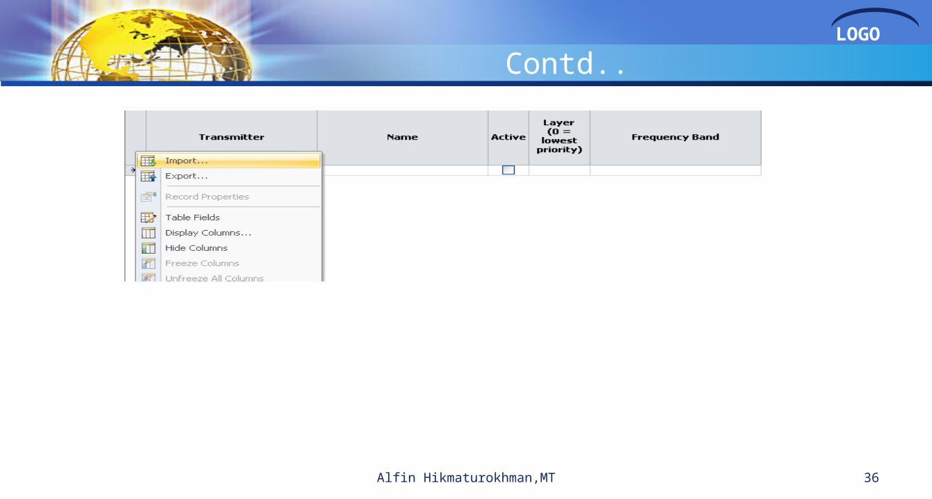
Cells Table To open the “Cells table”, right click on “Transmitters” in the Network tab and
select “Cells->Open Table”, as seen in the following figure. The cells for a site can be added only after the transmitter info is available in Atoll
Alfin Hikmaturokhman,MT 35
LOGO
Contd..
Alfin Hikmaturokhman,MT 36
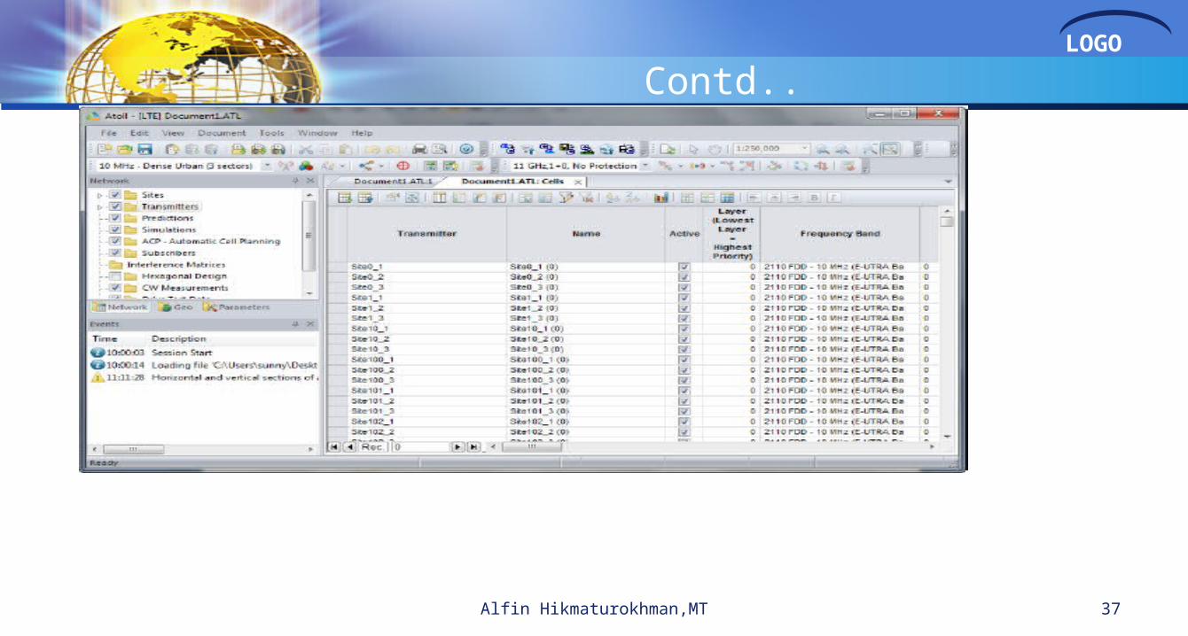
LOGO
Contd..
Alfin Hikmaturokhman,MT 37

LOGO
MIMO Systems in Atoll LTE Base stations and user equipment support MIMO systems
Gains graphs available in reception equipment
Numbers of transmission and reception antenna ports at base station and terminal
Antenna diversity modes in Atoll LTE Multiple Input Multiple Outputs (MIMO) systems
• Transmit/Receive Diversity (also called Space-Time Coding (STC) or Matrix A MIMO in other standards)– More than one transmission antenna to send the same data– Improvement of CINR Higher bearer Higher throughput– Usually used in coverage areas with bad CINR conditions
• Single-User MIMO (SU-MIMO) or Spatial Multiplexing (SM) (also called Matrix B MIMO in other standards)– More than one transmission antenna to send different data streams on each antenna– Improvement of throughput for a given CINR– Usually used in coverage areas with good CINR conditions
• Adaptive MIMO Switch (AMS)– Technique to switch from SM to Tx/Rx Diversity as CINR conditions get worse than a given threshold
38Alfin Hikmaturokhman,MT

LOGO
MIMO Settings Atoll allows users setting parameters related to MIMO according to their
requirement to simulate MIMO technology. In Parameters-> Network Settings -> Reception Equipment -> Default Cell
Equipment/Default UE Equipment.
Alfin Hikmaturokhman,MT 39

LOGO
Contd.. Right click on Transmitter folder in Network tab and select Open Table to set the
number of reception/transmission antennas for MIMO transmitter as seen in below figure.
Alfin Hikmaturokhman,MT 40

LOGO
Contd.. In Parameters -> LTE Parameters ->Terminals to set Antenna Diversity Support
as MIMO for terminal using MIMO,
Alfin Hikmaturokhman,MT 41

LOGO
Contd.. Cell in Network tab and select “Open Table” to set UL/DL diversity support types
for cell using MIMO
Alfin Hikmaturokhman,MT 42
cv
cv
cvc

LOGO
Smart Antenna Settings Open the properties dialogue of smart antenna models (Parameters tab -> Radio Network
Equipment -> Smart Antenna Models) to check the number of elements and single element pattern has been defined.
Alfin Hikmaturokhman,MT 43

LOGO
Contd..
In Transmitter table, select Smart Antenna Equipment for each sector
Alfin Hikmaturokhman,MT 44

LOGO
Contd.. Enable AAS capability on both sector side and terminal side. Cells table:
Alfin Hikmaturokhman,MT 45

LOGO
Contd..
Terminal properties:
Alfin Hikmaturokhman,MT 46

LOGO
Alfin Hikmaturokhman,MT 47
Coverage Predictions

LOGO
Create New PredictionTo create a new prediction, click Predictions->New, select the desired prediction study and click OK.
The new study is added in the Predictions folder. Click the new study-> Calculate, the prediction should be performed. Check the box on the left of the study to show the results.
48Alfin Hikmaturokhman,MT

LOGO
Contd..
Alfin Hikmaturokhman,MT 49

LOGO
Setting the Computation Zone
If there is no computation zone defined, the pathloss matrices for all transmitters will be calculated, based on the calculation radius and the signal threshold.
If the user wants to calculate the pathloss matrices only for a specific region, a Computation Zone can either be imported or directly drawn in the Map Window.
Alfin Hikmaturokhman,MT 50

LOGO
Define ZonesTo define a Computation zone, click the zone->Draw, an draw the polygon on the maps. It can also be imported. The defined zone can be deleted, edited, and exported if desired.
51Alfin Hikmaturokhman,MT

LOGO
Neighbours Allocation
Alfin Hikmaturokhman,MT 52

LOGOManually Allocation Feature
Right click on the “Transmitters” folder in the Network tab and select “Neighbours-> Intra Technology Neighbours”.
Alfin Hikmaturokhman,MT 53
LOGO
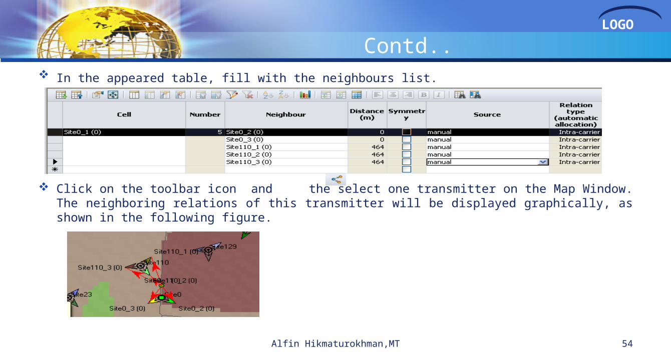
Contd.. In the appeared table, fill with the neighbours list.
Click on the toolbar icon and the select one transmitter on the Map Window. The neighboring relations of this transmitter will be displayed graphically, as shown in the following figure.
Alfin Hikmaturokhman,MT 54

LOGO
Contd..
Masukan neighbour site 129_1, 129_2, 129_3
Alfin Hikmaturokhman,MT 55
LOGO
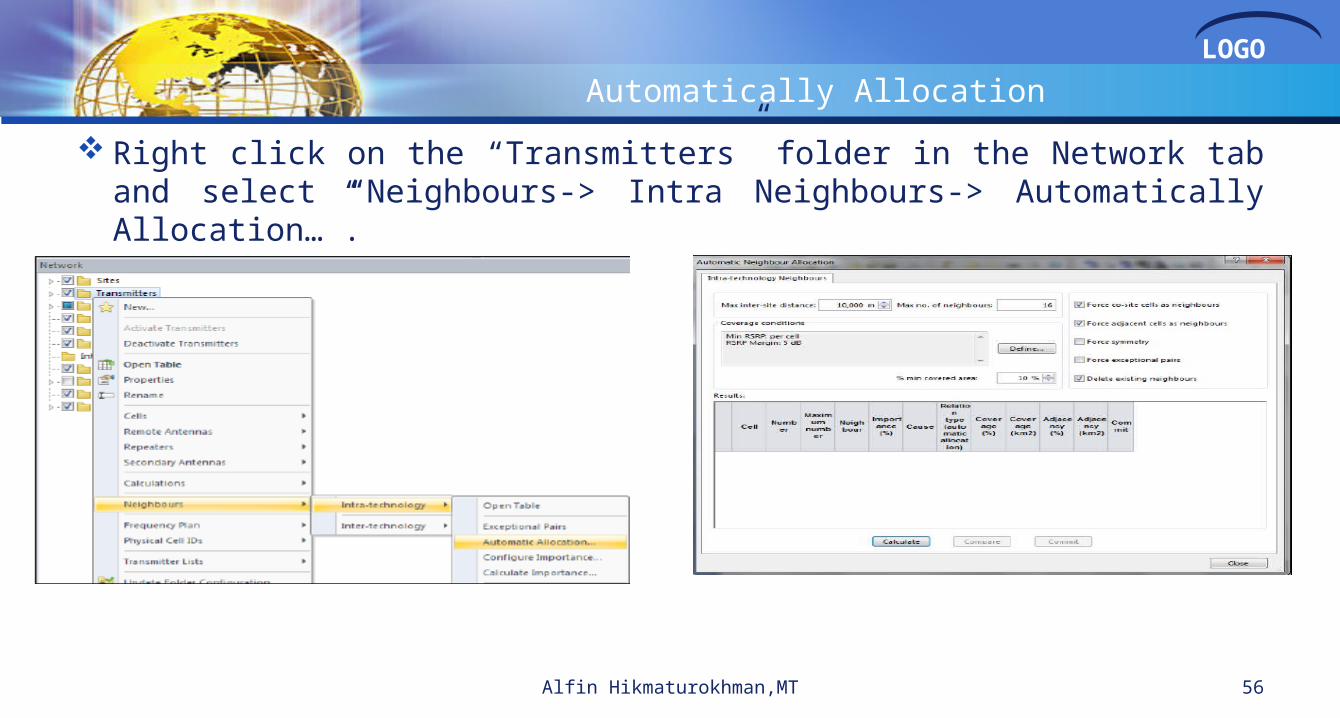
Automatically Allocation
Right click on the “Transmitters” folder in the Network tab and select “Neighbours-> Intra Neighbours-> Automatically Allocation…”.
Alfin Hikmaturokhman,MT 56

LOGO
Contd.. The automatic allocation results will be displayed in the same dialog box.
According to the results, the user may choose to commit the automatic neighbour allocation list by clicking on the “Commit” button.
Alfin Hikmaturokhman,MT 57
LOGO
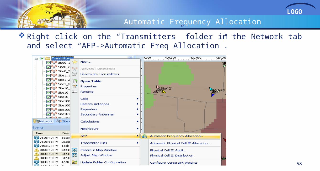
Automatic Frequency Allocation
Right click on the “Transmitters” folder in the Network tab and select “AFP->Automatic Freq Allocation”.
Alfin Hikmaturokhman,MT 58

LOGO
Contd.. Click on Calculate button in the bottom of dialog box to start the frequency
allocation. The allocation result will displayed in the same dialog box, the result could be committed to the cells table by clicking on Commit button.
Alfin Hikmaturokhman,MT 59

LOGO
contd Open the Cells table to check the updated the Channel Allocation Status will be
automatically changed to Allocated
Alfin Hikmaturokhman,MT 60
LOGO
Physical Cell ID Allocation
Alfin Hikmaturokhman,MT 61

LOGO
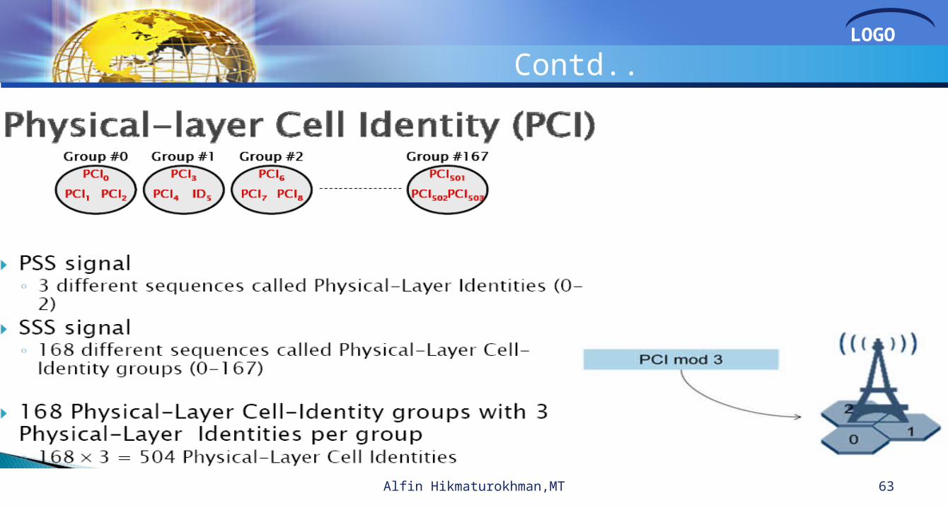
PCI Planning
Alfin Hikmaturokhman,MT 62
LOGO
Contd..
Alfin Hikmaturokhman,MT 63

LOGO
Contd..
Alfin Hikmaturokhman,MT 64

LOGO
Example : PCI Planning
There are 504 PCI availableFor Macro eNode B we use 0-443 (148 site’s)For IBS eNode B we reserve 444-503 for PCI Planning (20
site’s)
65Alfin Hikmaturokhman,MT

LOGO
Manual PCI Allocation
Right click on the “Transmitters” folder in the Network tab and select “Cells->Open Table”, input the PCI in the Physical Cell ID column as below
Alfin Hikmaturokhman,MT 66

LOGO
Automatic PCI Allocation
Right click on the “Transmitters” folder in the Network tab and select “Cells->Physical Cell IDs->Automatic Allocation
Alfin Hikmaturokhman,MT 67

LOGO
Channel Search Tool
Alfin Hikmaturokhman,MT 68

LOGO
Physical Cell ID Search Tool
Alfin Hikmaturokhman,MT 69

LOGO
PCI Allocation Audit
Alfin Hikmaturokhman,MT 70

LOGO
Alfin Hikmaturokhman.,ST.,MT
71Alfin Hikmaturokhman.,ST.,MT


![ACC Optim Report[1]](https://static.fdocuments.us/doc/165x107/577d23a01a28ab4e1e9a511b/acc-optim-report1.jpg)