
4G++: Advanced Performance Boosting -...
31
4G++: Advanced Performance Boosting Techniques in 4 th Generation Wireless Systems A National Telecommunication Regulatory Authority Funded Project Deliverable D3.1 Work Package 3 Channel-Aware Radio Resource Management and Scheduling in LTE and LTE-Advanced Systems List of Contributors (in alphabetical order): Name Title Role Amira Affifi External RA Main author of sections 2 and 3 (provided as a paper sent for review). Khaled Elsayed PI Co-author and reviewer of sections 2-5, editor of overall document. Mahmoud Ismail Lead Researcher Co-author and reviewer of sections 4 and 5. Rana Abd El-Aal RA Main author of sections 4 and 5.
Transcript of 4G++: Advanced Performance Boosting -...

4G++: Advanced Performance Boosting
Techniques in 4th
Generation Wireless Systems
A National Telecommunication Regulatory
Authority Funded Project
Deliverable D3.1
Work Package 3
Channel-Aware Radio Resource Management and
Scheduling in LTE and LTE-Advanced Systems
List of Contributors (in alphabetical order):
Name Title Role
Amira Affifi External RA Main author of sections 2 and 3 (provided as a paper sent for
review).
Khaled Elsayed PI Co-author and reviewer of sections 2-5, editor of overall
document.
Mahmoud Ismail Lead
Researcher
Co-author and reviewer of sections 4 and 5.
Rana Abd El-Aal RA Main author of sections 4 and 5.

D3.1: Channel-Aware RRM and Scheduling in LTE Page 2 of 31 Revision: 1.0
Abstract
This document provides an overview of the radio resource management functions in LTE/LTE-A as tackled
in the 4G++ project work package 3. The 4G++ project addresses two particular areas: LTE uplink
scheduling under QoS constraints and Coordinate Radio Resource Management for Coordinated Multipoint
Transmission systems.
List of Abbreviations
3GPP The Third Generation Partnership Project
AC Admission Control
AMC Adaptive Modulation and Coding
BS Base Station
CA Carrier aggregation
CoMP Coordinated Multi-Point
CS Coordinated Scheduling
CSI Channel State Information
DCS Dynamic cell selection
DL Downlink
eNB Evolved node B (Similar to the base station)
FPC Fractional Power Control
HARQ Hybrid Automatic Repeat Request
ICSGC Improved color-sensitive graph coloring
IRC Interference rejection combining
JP Joint Processing
LA Link Adaptation
LTE Long-Term Evolution
MRC Maximal Ratio Combining
OFA Orthogonal Frequency Allocation
OFDMA Orthogonal Frequency-Division Multiple Access
PHR Power Headroom Reports
PRB Physical Resource Block
PS Packet Scheduling
PUSCH Physical uplink shared channel
QoS quality-of-service
RA Resource Allocation
RB Resource Block
RFO Reuse Factor of One
RRE Remote Radio Equipment
RRM Radio Resource Management
SC-FDMA Single-Carrier Frequency Division Multiple Access
SDMA Space Division Multiple Access
SINR Signal to interference plus noise ratio
SLNR Signal to leakage plus noise ratio
SoN Self-Organizing Network

D3.1: Channel-Aware RRM and Scheduling in LTE Page 3 of 31 Revision: 1.0
SR Scheduling Request
UE User Equipment
UL Uplink

D3.1: Channel-Aware RRM and Scheduling in LTE Page 4 of 31 Revision: 1.0
Table of Contents
Abstract ....................................................................................................................................2
List of Abbreviations ................................................................................................................2
Table of Contents .....................................................................................................................4
List of Figures ..........................................................................................................................6
List of Tables ............................................................................................................................6
1 Introduction .......................................................................................................................7
2 LTE Uplink Scheduling: Problem Definition and Survey ................................................8
2.1 Problem Definition ................................................................................................................ 8
2.1.1 RRM Functionalities ................................................................................................................. 8
2.1.2 RRM Constraints and Challenges.............................................................................................. 8
2.1.3 Inputs to the RRM ................................................................................................................... 10
2.1.4 Formulation of LTE Uplink Scheduling Problem ................................................................... 10
2.2 Related Work ....................................................................................................................... 11
2.2.1 Channel Dependant Scheduling............................................................................................... 11
2.2.2 QoS Oriented Scheduling ........................................................................................................ 13
2.2.3 Uplink Power Control and Interference Coordination ............................................................. 15
3 Proposed LTE Uplink Scheduling Scheme .....................................................................18
4 Coordinated Radio Resource Allocation in CoMP .........................................................19
4.1 CoMP Schemes ................................................................................................................... 20
4.1.1 CoMP Transmission Schemes ................................................................................................. 20
4.1.2 CoMP Reception Schemes ...................................................................................................... 21
4.2 CoMP Resource Allocation Schemes ................................................................................. 22
4.2.1 Downlink CoMP Schemes ...................................................................................................... 22
4.2.2 Uplink CoMP Schemes ........................................................................................................... 23
5 Proposed Coordinated Resource Allocation Scheme in CoMP ......................................25
5.1 System Model ...................................................................................................................... 25
5.2 Efficient Suboptimal RA strategy ....................................................................................... 25
5.3 Complexity Evaluation ........................................................................................................ 26
5.4 Stopping Criteria ................................................................................................................. 26

D3.1: Channel-Aware RRM and Scheduling in LTE Page 5 of 31 Revision: 1.0
5.4.1 The Optimal SLNR Threshold ................................................................................................ 26
5.4.2 Marginal Utility ....................................................................................................................... 27
5.4.3 Marginal Utility with look-ahead criteria ................................................................................ 27
5.5 Simulation Results ............................................................................................................... 28
References ..............................................................................................................................28

D3.1: Channel-Aware RRM and Scheduling in LTE Page 6 of 31 Revision: 1.0
List of Figures
Figure 1: The RRM Design Problem Visualization ........................................................................................... 9
Figure 2: Contiguous Assignment of RBs in SC-FDMA ................................................................................... 9
Figure 3: UE-eNB Signalling ........................................................................................................................... 10
Figure 4: Cell scenario with several RRE ........................................................................................................ 19
Figure 5: Joint Processing CoMP ..................................................................................................................... 21
Figure 6: Dynamic Cell Selection CoMP ......................................................................................................... 21
Figure 7: Coordinated Scheduling CoMP ........................................................................................................ 21
Figure 8: Static Cell Clustering Example ......................................................................................................... 23
Figure 9: CoMP Cell Paradigm ........................................................................................................................ 25
Figure 10: Marginal Utility with Look-ahead Flow Chart ............................................................................... 28
Figure 11: Throughput Comparison for Different Stopping Approaches ........................................................ 28
List of Tables
No table of figures entries found.

D3.1: Channel-Aware RRM and Scheduling in LTE Page 7 of 31 Revision: 1.0
1 Introduction
As the services provided to mobile users become more demanding, the mobile telecommunications systems
must evolve to meet these expectations. The Third Generation Partnership Project (3GPP) is specifying the
Long Term Evolution (LTE) and LTE-Advanced as new radio access technology and network architecture
for providing considerable performance improvement at a reduced cost. This work package proposes a radio
resource management (RRM) scheme within the LTE/LTE-A framework. Specifically, we address two main
interesting problems: uplink scheduling with quality-of-service (QoS) constraints, and resource allocation in
coordinated scheduling for coordinated multipoint transmission (CoMP) systems.
To reach LTE's design goals set by 3GPP, LTE's new radio access technology and network architecture must
be exploited when addressing the RRM design problem. The RRM functionalities include Admission
Control (AC), Packet Scheduling (PS) including Hybrid Automatic Repeat Request (HARQ), and fast Link
Adaptation (LA) including Adaptive Modulation and Coding (AMC) and Fractional Power Control (FPC).
The RRM design problem can be summarized as providing these functionalities under the constraints
introduced by the used technology such as contiguity constraint of SC-FDMA, and the constraints introduced
by the design goals such as improving spectral efficiency and QoS provisioning. The goals of the first task
in this work package is to investigate, proposes, and evaluate schemes for channel-aware scheduling in the
uplink direction in LTE/LTE-Advanced. An important objective is to reduce interference in the uplink by
using the minimum possible power at cell edges. Moreover, in CoMP systems the current state of the art is
that the serving eNB selects resource blocks and power and provides this information to the cluster of eNB’s
that collaboratively transmitting to the UE. This is not optimum from the capacity point of view since other
cells could have quite different links. Therefore, the objective of the second task is to make the allocation
decision based on max sum rate seen collectively by the cluster not just the serving eNB.
This report is comprised of the following parts:
– An extended survey of LTE uplink scheduling schemes
– Initial model of LTE uplink scheduling scheme supplied as a paper currently under review
– A survey of resource allocation in CoMP
– Initial model of a coordinated resource allocation scheme in CoMP and results
D3.1: Channel-Aware RRM and Scheduling in LTE Page 8 of 31 Revision: 1.0
2 LTE Uplink Scheduling: Problem Definition and Survey
2.1 Problem Definition
The 3GPP LTE standard was specified based on a set of requirements and design targets. To achieve these
targets the LTE used new technologies such as multi-carrier, multiple antennae and packet switched radio
interface. While these technologies help improve system performance, they impose new constraints and
challenges for the design and implementation problem.
To exploit the new dimensions of frequency and space introduced by OFDM and MIMO respectively, cross
layer techniques between the physical layer and the link layers should be implemented. Some of these
techniques which exploit the frequency dimension include channel dependant scheduling, dynamic link
adaptation and power control. It is noted that optimizing the RRM functionalities depend on the physical
layer configurations and constraints.
In addition to the constraints and requirements introduced by the standard specifications and the
technologies used, the RRM design must consider the requirements and constraints of the different types of
applications or what is known as providing the appropriate QoS to the appropriate traffic type. Proportional
to the importance of this issue is its complexity as more diverse applications with different requirements are
introduced.
2.1.1 RRM Functionalities
As radio resources are scarce and at the same time the number of users and their demands increase,
managing the radio resources becomes a crucial point in the performance of any wireless network. The two
main resources that need management are the transmission bandwidth and uplink power. The RRM
functionalities are:
– Admission Control: This function ensures that a new user is not allowed to join the network unless
there is enough resources to meet its QoS requirements. This function is performed only during EPS
bearer establishment.
– Scheduling transmission bandwidth: The number of users is larger than the available bandwidth. The
scheduler function is to determine each TTI which users to be served, the transmission bandwidth
allocated to each user and the location of this bandwidth in the spectrum.
– Link Adaptation: The link adaptation determines the transport format of the packets for each user,
i.e. it assigns a modulation and coding scheme. It also performs power control to have the users
operate at a target SINR.
The overall RRM design is depicted in Figure 1.
2.1.2 RRM Constraints and Challenges
The implementation of the above RRM functionalities must meet the requirements of the system and users
while respecting the constraints of the technologies.
The constraints on the scheduler can be summarized as (1) the number of available PRBs, (2) for each PRB
at most one user can be assigned. For the link adaptation functionality the constraints are (1) the available
modulation schemes, (2) the available code rates, (3) the maximum transmission power.
SC-FDMA was chosen as the uplink transmission scheme for LTE. This adds a constraint on the scheduler
functionality that the PRBs allocated to one user must be contiguous in frequency as shown in Figure 2.

D3.1: Channel-Aware RRM and Scheduling in LTE Page 9 of 31 Revision: 1.0
Figure 1: The RRM Design Problem Visualization
Figure 2: Contiguous Assignment of RBs in SC-FDMA
One of the main requirements the RRM functionalities must meet are those related to the QoS parameters.
The RRM functionalities should provide each user with the QoS the connection was established based on.
This includes meeting the guaranteed bit rate, maximum tolerated packet delay and maximum tolerated
packet loss ratio.
Channel Estimation and
SINR calculation
SINR to CQI mapping
Time Domain Scheduler
Frequency Domain Scheduler
AMC
Power Control
QoS parameters
BSR
PHR
CQ
I S
INR
S
RS
TX BW
Allocation
MCS
TPC Commands

D3.1: Channel-Aware RRM and Scheduling in LTE Page 10 of 31 Revision: 1.0
Besides the constraints and requirements the RRM functionalities must address the issues of system
performance. Design of RRM algorithms should consider issues such as maximizing spectral efficiency and
overall system throughput, minimizing inter-cell interference and providing fairness among users.
2.1.3 Inputs to the RRM
To serve its purpose the RRM is provided with inputs to help it take informed decisions.
The channel conditions which are required for the link adaptation and scheduling can be estimated for the
whole bandwidth for each user with the help of the channel sounding reference signals. The SINR is
calculated for the SRS’s and then mapped to a CQI. For the downlink the UE sends CSI reports to the eNB.
To distinguish active users with data in their buffers from idle users, each user with data pending in its
buffers sends a one bit Scheduling Request (SR) to the eNB informing it with the need for UL grants.
The information about the amount of data available at each user’s buffers is collected by means of buffer
status reports.
The UE sends Power Headroom Reports (PHR) to the eNB to inform it about the amount of available power
the UE have which is used in the power control and scheduling functionalities of the RRM. The PHR can
also be used to estimate the downlink pathloss. The signalling between the UE-eNB is conceptually depicted
in Figure 1.
Figure 3: UE-eNB Signalling
2.1.4 Formulation of LTE Uplink Scheduling Problem
We provide the formulation for the uplink scheduling problem a mathematical optimization problem and
discuss that in the general form, it is an NP-hard problem.
Let the number of users in the system be given by N and the number of resources blocks C. Let ni , be the
achievable rate of RB },,2,1{ Cn when allocated to user },,2,1{ Ni i. Similarly, let nip , be the
uplink power transmitted by user i on RB n to achieve rate ni , and let }1,0{, ni indicate whether RB n
TPC
MCS
SRS
BSR
UE eNB
Buffer 1
Buffer 2
Buffer 3
Buffer 4
SR
UL Grant
RRM PHR

D3.1: Channel-Aware RRM and Scheduling in LTE Page 11 of 31 Revision: 1.0
is allocated to user i . Define Max
iP as the maximum allowed total power by user i . Let t refer to a specific
frame. The uplink scheduler determines at each scheduling instant t the matrix ][)( ,nit . The uplink
scheduling problem can be formulated as the following optimization problem:
N
i
C
n
ninit1 1
,,maxarg)(
(1)
Subject to
}1,0{, ni (2)
N
i
ni Cn1
, },,2,1{,1 (3)
Cnnmminini ,,3,2,1,1,, (4)
1,,3,2,1,1,, nnmminini (5)
},,2,1{,1
,, NiPp Max
i
C
n
nini
(6)
The constraint (3) insures that a RB is allocated to only one user, while constraints (4) and (5) take into
account the allocation contiguity for user i as mandated by SC-FDMA in the LTE uplink. On the other hand
constraint (6) puts an upper bound on maximum transmission power for user i . Further constraints can be
added, for example, if at any frame the rate seen by user i is required to be greater than a certain rate ir , this
can be captured by i
C
n
nini r1
,, . Alternatively, the rates for the different users can be required to satisfy
certain fairness constraints.
Another interesting constraint is handling HARQ retransmission, assuming synchronous non-adaptive
HARQ and that user i has scheduled retransmissions, then the scheduler should reserve certain blocks for the
user which can be captured by setting the constraint 1, ni for those RB’s that has been allocated in the
original transmission for the user.
As can be seen this formulation results in an ILP for the resource assignment problem and the solution is an
NP-complete problem. Solutions using ILP solvers can be tractable for small values of N and C. In our work
we design heuristics to obtain good solutions for the different types of problems. In addition, we handle the
constraints on users’ rates with fairness and delay constraints along with limiting uplink power.
2.2 Related Work
2.2.1 Channel Dependant Scheduling
Frequency Domain Packet Scheduling also known as Channel Dependant Scheduling exploits the multiuser
diversity to increase spectral efficiency and throughput. What is seen as a bad channel for one user is most
likely to be a good channel for another user. The scheduling decision is the assignment of resource blocks to
users in such a way as to maximize a utility function based on throughput. The channels for each user are

D3.1: Channel-Aware RRM and Scheduling in LTE Page 12 of 31 Revision: 1.0
obtained by providing the SRS to a channel estimation algorithm. For simulation purposes perfect channel
knowledge is assumed in the majority of the literature addressing this problem.
2.2.1.1 Heuristic Algorithms for Channel Dependant Scheduling
The following work tackled the channel dependant scheduling from a heuristic point of view to decrease
computational complexity and provide a cost efficient implementation.
S. Lee et al. in [1] evolved the conventional Round Robin algorithm and introduced four algorithms to
address the problem of uplink scheduling in the LTE.
– Algorithm 1: Carrier by Carrier in turn. Round robin on the RBs starting from RB number 1, the RB
is assigned to the user with the highest metric on the RB without violating the contiguity constraint.
– Algorithm 2: Largest Metric Value RB First. Same as algorithm 1 but instead of starting with RB
number 1 start with the RB with the highest metric value, the in-between RBs are assigned to the
same user.
– Algorithm 3: Riding Peaks. The idea is based that there is correlation between adjacent RBs i.e. if
for a user a certain RB has high metric it is with high probability that the neighboring RBs will also
have high metrics. Same as algorithm 2 look at the highest metric value RB first, the RB is assigned
to user i if the RB is adjacent to the previously assigned RBs of user i or user i has no RBs assigned
yet. Otherwise it is not allocated and we move on to the next RB.
– Algorithm 4: RB Grouping. Algorithm 3 is expected to yield good results if the frequency domain
exhibits high correlation between two adjacent RBs. However correlation in the frequency domain is
not strong which implies that even though we have an overall frequency correlation the granularity
of this correlation is not necessarily as small as one RB. To deal with this issue of small scale
variations the unit of consideration will be RB group. A RB group is a number of contiguous RBs
viewed as one block together.
In [2] a Search Tree Based packet scheduling algorithm is proposed. The idea is to draw a binary tree where
each node has 2 branches the maximum utility and the second maximum utility. Allocation is decided at the
end where the path with the highest overall global utility is chosen. In the simulations the bandwidth is
assumed equal and fixed for all UEs therefore neglecting the adaptive transmission bandwidth problem,
imperfect channel knowledge is considered through considering HARQ retransmissions, and open loop
power control is implemented.
In [3] three heuristic algorithms were proposed. First Maximum Expansion algorithm assigns resources
starting from the highest metric value and expanding the allocation on both sides, the allocation for a UE is
stopped whenever another UE with a higher metric is found. The second algorithm Recursive Maximum
Expansion is similar to the first one except that it performs a recursive search of the maximum. Minimum
Area Difference to the Envelope is a more computationally expensive algorithm than the previous two
however gives closer results to the optimal solution. This algorithm aims at minimizing the difference
between its cumulative metric and the envelope metric. Improvements over Round Robin algorithm have
been shown.
In [4] the authors combine the work of [2] and [3] and propose two improvements for the Recursive
Maximum Expansion Algorithm. The first algorithm give higher flexibility in the RB expansion by not
limiting the expansion only to the maximum but having it to be within a threshold, while the second
algorithm Improved Tree Based Recursive Maximum Expansion gives even more flexibility in the expansion
by considering the highest and second highest metric deriving a binary search tree. Results show that with a
little higher complexity around 15% gain in spectral efficiency is obtained compared with conventional
Recursive Maximum Expansion.

D3.1: Channel-Aware RRM and Scheduling in LTE Page 13 of 31 Revision: 1.0
The authors in [5] looked at the problem from a different view by focusing on investigating different
scheduling metrics, mainly a combination of two metrics throughput based in the time domain and SINR
based in the frequency domain. Scheduling metrics affect the priority of the users. Evaluations are based on a
RRM framework with open loop power control and AMC.
A Heuristic Localized Gradient Algorithm is discussed in [6]. The algorithm simplifies the optimal
Localized Gradient Algorithm by following a simple heuristic in allocating the RBs to the users while
maintaining the required allocation constraint and taking retransmission requests into consideration. The
basic idea is to search for the RB-user pair with the highest metric value and assigning this RB to this user, if
the user has previous allocations that is not contiguous to the new allocation, all in-between RBs are assigned
to the user. The HLGA is compared to a reference algorithm LGA which defines and solves an optimization
problem. In [7] the authors examined the performance of the HLGA when dynamic traffic models are
assumed. To solve the problem of different buffer occupancies and therefore different users' requirements, a
procedure called 'pruning' is introduced. The pruning procedure states that RBs are first assigned to users
according to the HLGA regardless of their traffic requirement. Extra RBs allocated to users are then
reallocated to either neighboring users in the spectrum or users with no assignments. Pruning is performed
on edge RBs to preserve the contiguity constraint.
2.2.1.2 Optimization Problem of Channel Dependant Scheduling
The channel dependant scheduling problem was addressed as an optimization problem to obtain an optimal
solution. As these solutions usually need high computation resources they are mostly used as a benchmark
and reference for other suboptimal or heuristic solutions. In [6] and [8], the authors discussed the
optimization problem and provided suboptimal algorithms to solve it.
In [6] the gradient metric was chosen as the scheduling metric for the scheme. The utility function is a
strictly concave smooth utility function. An integer programming assignment problem is formulated with a
contiguity constraint. The integer programming optimal solution assumes perfect channel knowledge, in case
of measurement delays and estimation errors, the selection rule occasionally picks rates that do not match the
channel capacity. Synchronous non adaptive HARQ is assumed to take care of these errors and therefore a
constraint is added to allocate to the users having HARQ processes operating on certain RBs those same RBs
until successful transmission is achieved. In this case the solution provided is not the optimal one.
In [8] a general LTE UL FDPS problem is formulated. The problem defines a profit function which is a
general term used to represent various scheduling policies. The aim is to schedule the RBs in a time slot such
that the profit is maximized. The LTE UL FDPS problem is shown to be NP-hard and therefore two
approximation algorithms are introduced which computes solutions close to the optimum. The first heuristic
algorithm is a greedy strategy based algorithm which divides the LTE UL FDPS problem into several sub
problems according to the profit and then apply a greedy method to each problem. The second algorithm is
based on a local ratio technique.
The aforementioned algorithms have all assumed full buffer traffic model, fixed traffic classes and only
focusing on increasing overall throughput with no regards to interference on other cells.
2.2.2 QoS Oriented Scheduling
QoS oriented scheduling considers in addition to increasing throughput, per-flow metrics such as packet loss
and packet delay. In today’s wireless networks, more diverse applications, such as video and interactive
gaming, are introduced leading to different QoS requirements. The scheduling scheme should consider these
variations when assigning resources. QoS parameters including maximum allowed packet delay, maximum
allowed packet drop ratio, priority and guaranteed bit rate GBR must be respected. In the channel dependant
scheduling problem, the utility function is usually a function of the overall rate is to be maximized under the

D3.1: Channel-Aware RRM and Scheduling in LTE Page 14 of 31 Revision: 1.0
contiguity constraint. When QoS classes are accounted for in the resource assignment, this will add further
constraints on the scheduler.
2.2.2.1 Downlink QoS Oriented Scheduling
The following papers discussed QoS-oriented scheduling but from the downlink point of view. Downlink
scheduling is a simpler problem than the uplink as the contiguity constraint is removed. Another issue that is
different in the downlink from the uplink is that the HOL packet delay in the downlink is available at the
eNB while in the uplink it is either estimated or the buffer status is used instead.
The authors in [9] expanded the channel dependant scheduling problem to include buffer status awareness.
AMC is also implemented where, the MCS is chosen depending on the CQI reported by the UE. Proportional
fairness is achieved by preferring users with good channel conditions to be scheduled but at the same time if
the user is scheduled frequently the priority of the user is decreased. A priority function is proposed to
achieve four objectives 1) maximize system throughput 2) decrease packet drop ratio 3) keep certain fairness
among users 4) guarantee QoS of multimedia services. The priority is a function of the buffer status, the
instantaneous data rate, the average data rate, priority of the service class and GBR for RT services. For each
subband the priority function is calculated for all the users and the subband is allocated to the user with the
highest priority on this subband.
In [10] a decoupled time and frequency domain scheduler is proposed. The time domain scheduler helps in
reducing the complexity of the frequency domain scheduler by minimizing the set of schedulable users.
Users are added to the set of schedulable users if they satisfy that they have data to be transmitted and that
the data has passed either the buffer amount threshold or the head of line threshold. The schedulable users
are then prioritized according to a set target bit rate. The frequency domain scheduler then selects for PRB k
the user n that maximizes a chosen metric. Three metrics are investigated
1) Proportional Fair:
, -
, -
where , - is the past average throughput of user n and , - is the estimated achievable throughput for
user n on PRB k
2) Proportional Fair Scheduled:
, -
, -
where , - is an estimate of the user throughput if user n was scheduled every sub-frame.
3) Carrier Over Interference to Average.
, -
∑ , -
where , - is an estimation of the SINR on the kth PRB of the n
th user. The denominator describes the
average channel quality of the user.
In [11] the authors propose a delay prioritized scheduling algorithm consisting of three steps. Step 1 the
algorithm computes for each user the remaining time of the HOL packet delay to approach the delay
threshold. Step 2 the user with the lowest difference between the HOL delay and the threshold is chosen.
Step 3 finds the RB with the highest gain for the selected user and assigns the RB to it.
D3.1: Channel-Aware RRM and Scheduling in LTE Page 15 of 31 Revision: 1.0
In [12] a similar approach is adopted where the users are classified into three categories according to their
HOL packet delay and then the packet scheduler allocates RBs to corresponding users according to their
priorities.
2.2.2.2 Uplink QoS Oriented Scheduling
The QoS oriented scheduling was discussed in the uplink in the following papers.
In [13] two algorithms are proposed which consider the end to end packet delay constraint in addition to the
contiguity constraint imposed in LTE uplink scheduling. The first algorithm goes through each RB and
assigns it to a user taking into account the contiguity constraint if the maximum delay and minimum
throughput requirements are satisfied for all the users. Otherwise it assigns first the users with critical delay
or throughput as long as RBs are available and do not violate the contiguity constraint. The second algorithm
differs from the first one in the use of a different metric value and that RBs are not assigned in order but with
respect to users with critical delay requirement. Both algorithms tend to assign one block per user and
therefore are not efficient in the case when the number of users is smaller than the number of RBs, also in
both algorithms some users may never be assigned RBs.
In [14] the constraint of the queuing delay is studied under the goal to minimize power transmission. An
optimization problem is formulated and a suboptimal algorithm is proposed and evaluated.
2.2.3 Uplink Power Control and Interference Coordination
The problem of power control is closely associated with inter-cell interference. An optimum transmission
power is the power that can maximize system throughput. System throughput is a function of the cell
throughput and the inter-cell interference. The higher the transmission power the higher the cell throughput
but also the higher the inter-cell interference and subsequently the inter-cell interference decrease the
throughput for the neighboring cells. So basically power control objective is to achieve a transmission power
that maximizes user and cell throughput but at a reasonable inter-cell interference level. The argument for
this concept is that if all eNB’s control the level of interference they cause to neighboring cells, then each
individual eNB will also receive limited interference from its neighbors resulting in an overall good
performance. This behavior is desirable as it is in synchrony with the concept of self-organization (SoN) that
is being promoted by 3GPP and other forums to enhance the configuration, optimization, and operations of
future wireless networks [15] [16].
The LTE uplink power control mechanism constitutes of a closed loop component operating around an open
loop point of operation. The open loop component is derived based on a parameterized power control
scheme. Conventional power control schemes assume full compensation for the pathloss where all users are
received with the same SINR, which means that the higher the pathloss the higher the transmission power.
Since the pathloss to the serving eNb is inversely proportional to the pathloss to the neighbouring eNB’s, the
conventional power control scheme with full compensation could lead to high inter-cell interference levels.
The uplink power equation as stated in the 3GPP LTE standard allows the use of Fractional Power Control
(FPC) where users with higher pathloss operate at a lower SINR requirement. To further improve the
performance in terms of interference a closed loop component is added to the open loop. The closed loop
component is left to the implementation of the vendor where usually it is associated with a SINR or
interference target.
While the open loop term determines the tradeoff between cell capacity and cell outage by compensating for
slow variations, the closed loop term affect the long term performance tradeoff between inter-cell
interference and system throughput by compensating for fast variations.
D3.1: Channel-Aware RRM and Scheduling in LTE Page 16 of 31 Revision: 1.0
2.2.3.1 Performance Evaluation of the LTE Uplink Power Control mechanism
In [17] and [18] the authors have evaluated the performance of the uplink power control mechanism defined
in the LTE standard.
The authors in [17] evaluates the FPC equation and studies the effect of the different parameters on the
interference levels and the SINR which gives an indication on the throughput. The paper’s focus was only on
the open loop power control therefore depending on the aim of the PC scheme whether it is to increase
capacity or to improve outage performance, a choice for the different parameters of the open loop power
control equation was made to achieve that.
While [17] focused on the open loop performance, [18] evaluated the performance of both the open loop and
closed loop power control mechanisms. Investigations of the different parameter sets to give (a) high bit rate
and (b) high capacity have been done.
2.2.3.2 Uplink Power Control and ICIC
The following work studied the uplink power control problem and proposed power control techniques but
neglected the effect of some RRM functionalities.
In [19] the author designed and implemented a closed loop power control scheme in combination with the
fractional pathloss compensation factor. An investigation for the different values of the pathloss
compensation factor has been provided as well as a choice for the optimal value that gives best cell edge and
mean user throughput. The SINR Target is set by the eNB as the target SINR that a UE should be using. The
SINR Target affects two parameters, the throughput and the interference. A mathematical model for setting
the SINR Target based on the pathloss is described. The proposed model assigns a higher SINR Target for
users with low pathloss therefore allowing these users to transmit at a higher power. Implementing this
model will decrease the inter-cell interference but at the expense of lower throughput for the cell edge users.
In [20] the author studied the open loop power control and introduced two closed loop power control
algorithms to enhance the performance.
The first algorithm is designed to set the transmission power spectral density according to the tradeoff
between the UE’s generated signal and interference powers to achieve a higher SINR for this UE. The
algorithm calculates the total interference generated by a UE and compares it to an interference limit. While
the interference spectral density limit is equal to all users the interference limit is dependent on the allocated
bandwidth to the users, but the author assumes equal bandwidth allocation to all users in the simulation. The
transmitting power spectral density is set using the interference spectral density limit.
A further modification is introduced by adding a factor similar to the pathloss compensation, to tune the
pathloss of the UE to the neighbouring eNBs. The two pathloss terms (pathloss between UE and serving
eNB, and pathloss between UE and neighbouring eNBs) with their compensation factors are combined in a
formula to obtain the transmitting power spectral density.
The second algorithm is designed to set the transmission power according to a throughput measure. While a
user may represent a better tradeoff between signal and interference powers, it is not necessary to represent a
better tradeoff between gain in throughput and interference. For each user two parameters are calculated, the
gain to the system calculated as the increase in throughput due to the increase in power, and the cost to the
system calculated as the increase in interference due to the increase in power. To calculate the increase in
throughput an estimate of the interference this user is experiencing is estimated. An “interference budget” of
the cell is managed by allowing iteratively one UE to increase its transmission power by one step until the
target interference is met. The UE will be chosen based on the gain/cost criteria.

D3.1: Channel-Aware RRM and Scheduling in LTE Page 17 of 31 Revision: 1.0
In [21] an uplink radio resource management scheme is proposed with an emphasis on admission control,
packet scheduling and handover. The admission control algorithm is based on fractional power control. The
admission decision for a new user is based on the availability of enough PRBs to satisfy his QoS
requirements. To calculate the number of PRBs required for fulfilling the requested GBR, the open loop
fractional power control equation is used. The number of required PRBs of existing users is obtained by
using the average number of PRBs allocated to these users by the packet scheduler.
The admission control algorithm is then combined with a packet scheduler. The packet scheduling is done in
two phases: Time Domain and Frequency Domain. The time domain scheduler prioritizes the users
according to their GBR requirements giving higher priority to the user further below his GBR and then
selects N users to input to the frequency domain scheduler. The frequency domain scheduler allocates
flexible number of PRBs to the users by using an adaptive transmission bandwidth based scheduling which
aims at maximizing the sum of a frequency domain metric. QoS is included in the frequency domain by
weighting the frequency domain metric according to the QoS requirements. The combined admission control
and packet scheduling is evaluated for different traffic profiles.

D3.1: Channel-Aware RRM and Scheduling in LTE Page 18 of 31 Revision: 1.0
3 Proposed LTE Uplink Scheduling Scheme
The 4G++ project team working on the uplink scheduling scheme devised a QoS based uplink scheduling
scheme combining uplink power control and was documented in the paper titled “A Radio Resource
Management Framework for the 3GPP LTE Uplink”. This paper is attached as a PDF and is currently under
review.
D3.1: Channel-Aware RRM and Scheduling in LTE Page 19 of 31 Revision: 1.0
4 Coordinated Radio Resource Allocation in CoMP
The capacity of wireless cellular networks is mainly restricted by interference. In cellular systems, a
geographical region is divided into cells. These handle interference through the use of pre-defined frequency
reuse patterns so that near cell-edge users belonging to adjacent cells do not share similar frequencies.
Recently, as bandwidth progressively becomes a more scarce resource, and future cellular networks shift
gradually closer to the maximal frequency reuse of unity. Consequently, the Radio Resource Management
(RRM) as well as scheduling will play an essential role in upcoming future networks.
Coordinated multi-point (CoMP) transmission is one of the candidate techniques for Long Term Evolution-
Advanced (LTE-A) systems to increase the average cell throughput and cell-edge user throughput in both the
uplink and downlink. The basic idea of CoMP is to eliminate the interference through cooperation between
neighbor cells and turns interference from neighbor cells into useful signal. Although CoMP naturally
increases the system complexity, it provides significant capacity and coverage benefits, making it worth a
more detailed consideration. In this survey, different CoMP systems are investigated. The aim of this survey
is to study different RRM, power control, and scheduling methods for interference mitigation together with
CoMP to achieve a considerable gain in terms of capacity and cell-edge user throughput [22].
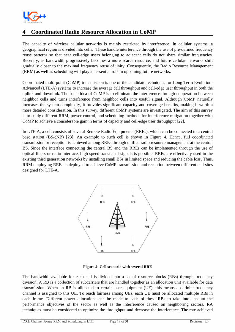
In LTE-A, a cell consists of several Remote Radio Equipments (RREs), which can be connected to a central
base station (BS/eNB) [23]. An example to such cell is shown in Figure 4. Hence, full coordinated
transmission or reception is achieved among RREs through unified radio resource management at the central
BS. Since the interface connecting the central BS and the RREs can be implemented through the use of
optical fibers or radio interface, high-speed transfer of signals is possible. RREs are effectively used in the
existing third generation networks by installing small BSs in limited space and reducing the cable loss. Thus,
RRM employing RREs is deployed to achieve CoMP transmission and reception between different cell sites
designed for LTE-A.
Figure 4: Cell scenario with several RRE
The bandwidth available for each cell is divided into a set of resource blocks (RBs) through frequency
division. A RB is a collection of subcarriers that are handled together as an allocation unit available for data
transmission. When an RB is allocated to certain user equipment (UE), this means a definite frequency
channel is assigned to this UE. To reach fairness among UEs, each UE must be allocated multiple RBs in
each frame. Different power allocations can be made to each of these RBs to take into account the
performance objectives of the sector as well as the interference caused on neighboring sectors. RA
techniques must be considered to optimize the throughput and decrease the interference. The rate achieved

D3.1: Channel-Aware RRM and Scheduling in LTE Page 20 of 31 Revision: 1.0
by a UE depends on: the downlink channel environment of the UE, the number of RBs allocated to each UE,
the power allocated to each RB, and the implemented interference approach [24].
In [25], RB optimization was explored considering a single RB. Two sectors and two UEs were considered
such that each sector serves one UE. The purpose was to maximize the sum rate for both UEs. The
conclusion was that the optimal power allocation is binary; either both sectors transmit with full power or
just one of them transmits at full power and the other is turned off.
In the case of multiple RBs, an algorithm must determine which RB should be allocated to a specific UE and
how much power should be allocated to each of the scheduled RBs given the overall power limitation. An
optimization problem should be solved to maximize the sum rate subject to power and bandwidth constraints
while taking into consideration the interference between sectors. In [25], a model with two sectors and
multiple RBs was considered. It was shown that if one RB is used by both sectors, then all RBs need to be
used by both sectors (i.e. a frequency reuse of 1). Similarly, if one RB is used by exactly one sector, then all
RBs need to be used by exactly one sector. Moreover, it was stated that uniform power allocation is optimal,
which is not clearly proved. It might be optimum in case of one user per sector (the very simplified case
assumed in the paper); however, more study is required in order to prove that it is optimal in case of the
existence of more than one user that needs to be served simultaneously. Hence, in the general case (multi-
user case); optimal power allocation may or may not be uniform.
4.1 CoMP Schemes
CoMP is a technology introduced for LTE-Advanced to meet the requirement of IMT-Advanced. CoMP
systems are able to exchange data, control information and Channel State Information (CSI) between all
RREs under the command of the eNB and, consequently, coordinate interference. In other words, the RREs
will coordinate together to serve the UEs in order to reduce the interference. The main objectives of CoMP
are to mitigate the interference, provide high spectral efficiency over the entire cell area, and increase the
overall throughput especially the cell-edge throughput [24].
4.1.1 CoMP Transmission Schemes
In the downlink (DL) of CoMP systems, several approaches are often considered. The first approach is Joint
Processing (JP) where the data is made available at each RRE and is transmitted from several RREs
simultaneously to each UE. Other approaches include; Dynamic cell selection (DCS) and Coordinated
Scheduling (CS) where, in both cases, the data is transmitted from one RRE at a time with scheduling
decisions being made with coordination between RREs.
4.1.1.1 Joint Processing (JP)
Multiple RREs work as a distributed antenna array under coordination of the eNB. Each UE may receive
useful signals from multiple RREs. In other words, multiple RREs are allowed to transmit the data to a
single UE simultaneously over the same RB (i.e. from the serving RRE and non serving RREs as well). The
main target of JP is to improve the coverage and the cell edge user throughput by maximizing the Signal-to-
interference-plus-noise ratio (SINR). The RREs’ outputs are chosen in ways to minimize the interference,
and hence to increase the downlink system capacity. When the interference is mitigated, the links can operate
in the high SINR regime. This enables the cellular network to enjoy the great spectral efficiency
improvement associated with using multiple RREs. Moreover, by using the multiple coherent transmissions,
the cell-edge user throughput will be enhanced. Figure 5 shows JP in the DL. JP requires the exchange of UE
data among RREs as well as UE channel information and consequently, requires significant backhaul
resources; high requirements in terms of signaling and measurements, as well as high speed links or
dedicated radio links are needed [24]. In [22] a JP scheme has been proposed and it has been shown that this
scheme can bring significant gains to both the average cell throughput and the cell-edge user throughput.

D3.1: Channel-Aware RRM and Scheduling in LTE Page 21 of 31 Revision: 1.0
Figure 5: Joint Processing CoMP
4.1.1.2 Dynamic Cell Selection (DCS)
In this approach, the data is transmitted from a single RRE. However, the decision of which RRE should
transmit is done jointly. For example, the RRE with the minimum path loss could be selected through fast
scheduling. Figure 6 illustrates the DCS idea. The data must be available at all cooperative RREs, but only
the selected one sends the data, and the others will be muted. Since; the best RRE is selected and also the UE
does not receive interference from the other neighbouring RREs, the SINR will be improved and the
throughput will be enhanced.
Dynamic fast selection is done
based on path loss
Figure 6: Dynamic Cell Selection CoMP
4.1.1.3 Coordinated Scheduling (CS)
In this case, a transmission to a scheduled UE is performed by a unique RRE (each UE receives the data
from a single RRE), see Figure 7 for reference. But; the RREs coordinate their transmissions using
scheduling and transmission weights that are jointly adapted for all UEs in order to reduce the unnecessary
interference. So, the cell-edge user throughput can be improved due to the increase in the received SINR.
The basic difference between this approach and the DCS is that it is not based on path-loss. It has many
different algorithms for scheduling so as to reduce the interference [24].
Interference coordination
Figure 7: Coordinated Scheduling CoMP
4.1.2 CoMP Reception Schemes
In CoMP reception in the uplink (UL), the physical uplink shared channel (PUSCH) is received at multiple
cells. In this case, maximal ratio combining (MRC) is used at multiple RREs. CoMP has reception schemes

D3.1: Channel-Aware RRM and Scheduling in LTE Page 22 of 31 Revision: 1.0
such as interference rejection combining and coordinated scheduling reception. In [24], the cell throughput
and cell edge user throughput performance were evaluated for CoMP reception schemes.
4.1.2.1 Interference Rejection Combining (IRC)
In this approach, multiple UEs transmit the PUSCH simultaneously using the same RB; however, received
weights are generated so that the received SINR or signal power after combining at the central BS is
maximized. The minimum mean squared error (MMSE) or zero forcing (ZF) algorithms are typically used to
combine the received PUSCHs at multiple cell sites. Cell-edge user throughput is improved due to the
increase in the received signal power [24].
4.1.2.2 Coordinated Scheduling Reception
In this case, only one UE transmits the PUSCH using an RB based on the coordinated scheduling among
cells in CoMP reception. Using this approach, the cell-edge user throughput will be improved as shown in
[24].
4.2 CoMP Resource Allocation Schemes
Finding an optimal RA for CoMP schemes so as to maximize the sum rate is a very complicated problem.
Hence, many suboptimal strategies have been proposed.
4.2.1 Downlink CoMP Schemes
CoMP appears as a promising technology to boost system throughput and to allow for an efficient RA. In
[26], a model was proposed that addresses the downlink of a CS system. The model is as follows: each eNB
has several geographically distant RREs. All signal processing is accomplished at the eNB. A group of
adjacent RREs are called a group cell, and they serve UEs within their coverage area. An SINR matrix is
formulated for all available RBs, the row vectors denote user flags and the column vectors denote carrier
flags. Elements in the matrix denote the SINR value of a certain user over a certain subcarrier. The RB is
assumed to be K subcarriers. The maximum consecutive K elements in the SINR matrix are chosen. Assume
those elements are in the ith row and span the jth through the (j+k)th columns. This means that the ith UE
will be allocated the jth through the (j+k)th subcarriers. After this allocation step, those elements will be
cleared to zeros in the matrix until the UE releases those subcarriers (RB).
Although simulation results in [26] showed that this technique provides high gains in terms of throughput
and reduces the blocking probability, this technique does not maintain fairness among users; For example, if
a certain user has a very good channel, all subcarriers (RBs) might be allocated to him/her and the other
users will not get a chance to be served. Moreover, since the throughput is calculated as a sum rate, then it
will never show the exact distribution of RBs among users. Consequently, a necessary update to this
technique is to limit the number of RBs allocated to each user to a certain threshold. By this, other users will
get a chance to be served even if they face bad channels.
In [27], RA algorithms that exploit coordination in the DL of CoMP systems to improve system throughput
have been proposed. Spatial multiplexing techniques have been applied for joint data transmission. In
particular, Space Division Multiple Access (SDMA) and precoding techniques have been used to achieve
throughput gains by exploiting the spatial degrees of freedom. The scheduling algorithm proposed was for JP
CoMP systems in which users are multiplexed via SDMA schemes. In such systems, the transmission quality
considerably degrades if users with spatially correlated channels are to be served over the same RB. Hence,
the target of the work presented in [27] is to serve UEs that are highly correlated over different RBs so as to
reduce interference. The approach presented uses zero forcing SDMA precoding schemes by deciding, for

D3.1: Channel-Aware RRM and Scheduling in LTE Page 23 of 31 Revision: 1.0
each RB, which users are to be served to maximize the performance. It was shown that quite high throughput
gains are achieved through the proposed RA algorithms.
In [28], carrier assignment in the DL JP CoMP has been investigated through the use of Carrier aggregation
(CA). Carrier assignment problem has been abstracted into a graph coloring problem, and an improved
color-sensitive graph coloring (ICSGC) algorithm has been proposed to find out a suboptimal solution. The
ICSGC algorithm has shown high gains in terms of total throughput.
In [29], a JP CoMP in the DL is proposed where the BSs are grouped together in a static cluster. Several
cluster strategies are investigated as well. Results have been provided for various system loads for different
static cell clustering approaches. An example to a static cell clustering is shown in Figure 8. In this example
each cluster consists of three hexagonal cells. It has been assumed that each UE belongs to only one cluster
and it is served by all BSs within the same cluster. The model addressed assumes that there is no
coordination between clusters.
Cluster 3
Cluster1 Cluster 2
Figure 8: Static Cell Clustering Example
The model proposed in [29] is a centralized model, where there is a central scheduler available in each
cluster. The central scheduler in each cluster has the knowledge of the CSI of all UEs being served by the
same cluster and it is responsible for managing all resources of the cluster. Therefore, one of the cells of the
cluster is preconfigured in the proposed architecture as master cell. All other cells within the cluster act as
slaves. Once the central scheduler has allocated the resources to the scheduled UEs, the information of the
resource allocation is distributed to the rest of the BSs. The results show that the JP CoMP with static cell
clustering can really enhance the system throughput significantly.
In [30], a DL JP CoMP transmission approach of an LTE-A operating in real time has been implemented and
evaluated. Since the first requirement of JP CoMP is that the physical layer and radio front-ends are tightly
synchronized, a precise clock reference has been obtained from the global positioning system (GPS). Many
features besides clock synchronization have been addressed, such as; synchronous data exchange between
the base stations; cell-specific pilots; feedback of multi-cell CSI; and precoder design. The proposed model
consists of a group of BSs forming a cluster in which each BS in the cooperation cluster has the same CSI
and data available, and it can compute independently from other BSs. In order to evaluate the proposed trial,
Interference-limited transmission experiments have been conducted using optimum combining with
interference-aware link adaptation and cross-wise interference cancellation between the cells. It has been
proved that JP CoMP can improve the total throughput in real implementations.
4.2.2 Uplink CoMP Schemes
In [31], a heuristic approach for a model of an UL transmission of a multi-cell system has been studied. Its
objective is maximizing the sum rate subject to specific power constraints as well as minimizing the total
power needed to meet a sum-rate target. Those two objectives are achieved by optimizing the SINR targets

D3.1: Channel-Aware RRM and Scheduling in LTE Page 24 of 31 Revision: 1.0
in multiple cells so as to minimize the total power and also to maximize the sum rate. Setting SINR targets is
an efficient mean to control fairness and multi-cell throughput performance. Also there is no delay due to
setting the SINR targets since CoMP systems allow the adjustment of these SINR targets on a time scale that
is similar to scheduling and power control. Significant gains of the joint SINR target and power optimization
is achieved depending on the degree of fairness imposed.
In [32], a heuristic UL scheduling scheme in CoMP has been proposed, in which UEs are connected to RREs
deployed throughout the cell and a central BS. Results show that systems with RREs achieve better
throughput than systems with conventional BS while allowing edge users better chances of accessing the
resources.
In [33], a real implementation of Uplink CoMP has been introduced. Many challenges have been addressed
such as multi-cell synchronization and multi-cell channel estimation. The model addressed is an outdoor
deployment of two cooperating BSs and two UEs. It has been proved that the Uplink concept do in fact yield
significant spectral efficiency gains.

D3.1: Channel-Aware RRM and Scheduling in LTE Page 25 of 31 Revision: 1.0
5 Proposed Coordinated Resource Allocation Scheme in CoMP
This sections presents a sophisticated Resource Allocation (RA) technique based on Signal-to-Leakage-plus-
Noise-Ratio (SLNR) for LTE-Advanced. In addition, it compares the proposed strategy to the RA based on
Signal-to-Interference-plus-Noise-Ratio (SINR) strategy. This report provides a comprehensive comparison
between two RA strategies; the first strategy is our proposed scheme based on SLNR, and the second one is
scheme addressed in [27] based on SINR. Both strategies are analyzed through simulations. Both algorithms
take advantage of coordination in the downlink of CoMP system to control the interference and improve the
overall performance. Furthermore, it discusses the complexity evaluation for both strategies. It is shown that
the RA strategy based on SLNR achieves an improved performance compared to [27].
5.1 System Model
The CoMP cell model consists of one eNB, M RREs under its control, and serves K UEs. A CoMP cell
paradigm is shown in Figure 9. There exists N Resource Blocks (RBs) in the system and each of them may
be assigned to one or more UEs. Uniform Power Allocation among RBs is considered and the overall
transmit power available on each RRE p is uniformly divided among the N RBs. So, the power allocated to
each RB is simply: pn = p/N.
Figure 9: CoMP Cell Paradigm
In this system, the major link measurement considered is the Signal-to-Leakage-plus-Noise-Ratio (SLNR) of
the UEs in the system. The SLNR β considered at UE k can be expressed as:
| |
∑ | |
| |
, (7)
where * + , is the channel vector (i.e. Which models the connection between the UE and
all M RREs of the CoMP cell) , is the weighting vector for the link connecting all the RREs of the CoMP
cell and the UE, and is the Additive White Gaussian Noise.
In [27], CS-CoMP model was also studied; the major metric considered was the SINR measured at each UE.
In contrast, our proposed model considers SLNR as a major metric, which greatly reduce complexity and so
it is considered more suitable for real cellular systems.
5.2 Efficient Suboptimal RA strategy
For each CoMP cell, the scheduler will select a group of UEs to be given data over the same RB. The group
of UEs sharing the same RB will be called UE-set (S). Scheduling decisions can be taken to determine
dynamically which UEs can simultaneously use the same RB.

D3.1: Channel-Aware RRM and Scheduling in LTE Page 26 of 31 Revision: 1.0
The weighting vector will be set in order to maximize (7).
The UE-set will be formulated in the following manner:
a. The UE with maximum SLNR will be added initially to the UE-set.
argk max { },
b. Leakage value vector from UE-set in the direction of the rest of UEs will be calculated.
| | ,
c. The UE with the smallest amount of leakage will be added to the UE-set.
args min { }
d. Repeat from step b till the minimum overall leakage value reaches a certain threshold or
repeat from step b till the number of UEs in the set reaches certain value.
5.3 Complexity Evaluation
When it comes to complexity, SLNR strategy is way enhanced than SINR strategy. Maximizing the SLNR
metric for each user simply needs m iterations, where m is the number of RREs. This is for the reason that
maximizing the SLNR for each user is an independent process (i.e. each user has only m possibilities, and
its SLNR value is not function of other users). Consequently, the complexity of maximizing the SLNR
metric for each user is of order m.
On the contrary, maximizing the SINR metric is very exhaustive process, as the SINR for each UE cannot be
optimized independently. This is because the interference at each UE is dependent on the other UEs’ links.
Thus, to optimize the SINR metric for a certain UE, it should try linking with all possible links (m
possibilities). Moreover, for each possibility it should try linking other users with all possible links.
Accordingly, the complexity of maximizing the SINR metric for each user is of order:
Complexity order
( ) ,
( )
( ) , otherwise
In [27], the SINR metric was not maximized (because as described above it is an extremely complicated
process). However, the weights corresponding to the maximum channel gain have been selected, and then
the SINR metric has been computed.
5.4 Stopping Criteria
Choosing the stopping criteria is extremely important step as it directly reflects on the throughput. So to
guarantee the throughput enhancement the following stopping criteria was investigated.
5.4.1 The Optimal SLNR Threshold
The optimal SLNR threshold is the value that is responsible for terminating the RA strategy as described in
the previous section. The relationship between the optimal SLNR threshold and the number of UEs per cell
is assumed to be linear. The precise equation is provided in the Appendix.
The RA strategy based on SLNR assures stopping when achieving nearly the highest throughput per RB. On
the other hand, the RA strategy based on SINR terminates when the throughput decreases which does not
assure achieving the highest value. For example, consider the scenario where three users are grouped and if a

D3.1: Channel-Aware RRM and Scheduling in LTE Page 27 of 31 Revision: 1.0
fourth UE is added, the total throughput will decrease (SINR strategy will come to an end here). However,
adding the fourth UE may be useful if by adding a fifth one; the total throughput will increase more than it
was when the group had only three UEs. Such scenario is expected to occur. As for adding a new UE to the
group sharing the same RB, there is a throughput loss as well as a throughput gain and both values depend
on the channel environment.
5.4.2 Marginal Utility
In this method a utility function is defined as the log function. In this stopping approach, a condition is
checked so as to allow sharing the RB (to allow grouping). This condition is:
+
,
(8)
In which, is the utility function of the UE that is recently added to the set,
is the Utility of
UEs previously in the group computed after adding the new UE, and is the Utility of the set
computed before adding the new UE. If equation (8) is satisfied then the UE will be added; otherwise the
grouping will be terminated.
This approach is efficient and provides high overall throughput gains but it doesn't take into consideration
the case when the throughput drops at once while it has not reached the maximum throughput (critical peak
that is supposed to be reached) and so the algorithm might terminate before reaching the highest achievable
throughput.
5.4.3 Marginal Utility with look-ahead criteria
In this method, the same marginal utility condition is used. However, if the condition is not fulfilled, there is
an extra possibility to add the UE to the set via constructing a temporary set that includes the original set plus
(where is the user that may or may not be added to the set. Then another user ( ) will be
selected and the marginal condition will be checked for the temporary set with . If it is still not
satisfied then the algorithm will terminate with the original set (not the temporary). However, if the condition
is fulfilled then the algorithm will terminate with a new set which is the temporary set and .The
algorithm is described in more details in Figure 10.

D3.1: Channel-Aware RRM and Scheduling in LTE Page 28 of 31 Revision: 1.0
Temp set = UE set + UE i
UE i+1
UE set UE i
o/p set = UE set + UE i
Not Satisfied
Marginal Utility condition
Satisfied
Marginal Utility condition
o/p set = Temp set + UE i+1Satisfied
o/p set = UE set
Not Satisfied
Figure 10: Marginal Utility with Look-ahead Flow Chart
5.5 Simulation Results
The proposed strategy achieves high throughput gains as shown in Figure 11.
Figure 11: Throughput Comparison for Different Stopping Approaches
As shown, The RA strategy based on SLNR with threshold presents performance about an average of 50%
higher than that of the SINR strategy. It is basically due to the perfect choice of the stopping threshold and
also for the reason that the weights are determined more accurately so as to maximize the SLNR metric for
all UEs. SLNR strategy with marginal utility with look-ahead criteria presents a gain of an average of
approximately 45% higher than that of the SINR strategy, and finally SLNR strategy based on marginal
utility only presents a gain of an average of approximately 35% compared to that of the SINR strategy.
References

D3.1: Channel-Aware RRM and Scheduling in LTE Page 29 of 31 Revision: 1.0
[1] S. Lee, I. Pefkianakis, A. Meyerson, S. Xu, and S. Lu, "Proportional Fair Frequency-Domain Packet
Scheduling for 3GPP LTE Uplink," in Proc INFOCOM., 2009, pp. 2611-2615.
[2] F. D. Calabrese et al., "Search-Tree Based Uplink Channel Aware Packet Scheduling for UTRAN
LTE," in Proc VTC Spring., 2008, pp. 1949-1953.
[3] L. Temino, G. Berardinelli, S. Frattasi, and P. E. Mogensen, "Channel-aware scheduling algorithms for
SC-FDMA in LTE uplink," in Proc PIMRC., 2008, pp. 1-6.
[4] F. Liu, X. She, L. Chen, and H. Otsuka, "Improved Recursive Maximum Expansion Scheduling
Algorithms for Uplink Single Carrier FDMA System," in Proc VTC Spring., 2010, pp. 1-5.
[5] F. D. Calabrese, C. Rosa, K. I. Pedersen, and P. E. Mogensen, "Performance of Proportional Fair
Frequency and Time Domain Scheduling in LTE Uplink," in Proc European Wireless., 2009, pp. 271-
275.
[6] M. Al-Rawi, R. Jantti, J. Torsner, and M. Sagfors, "Opportunistic Uplink Scheduling for 3G LTE
Systems," in Proc 4th IEEE Innovations in Information Technology., 2007, pp. 705-709.
[7] M. Al-Rawi, R. Jantti, J. Torsner, and M. Sagfors, "On the performance of heuristic opportunistic
scheduling in the uplink of 3G LTE networks," in Proc PIMRC., 2008, pp. 1-6.
[8] H. Yang, F. Ren, C. Lin, and J. Zhang, "Frequency-Domain Packet Scheduling for 3GPP LTE Uplink,"
in Proc INFOCOM., 2010, pp. 2597-2605.
[9] Y. Lin and G. Yue, "Channel-Adapted and Buffer-Aware Packet Scheduling in LTE Wireless
Communication System," in Proc WiCOM., 2008, pp. 1-4.
[10] G. Monghal, K. I. Pedersen, I. Z. Kovacs, and P. E. Mogensen, "QoS Oriented Time and Frequency
Domain Packet Schedulers for The UTRAN Long Term Evolution," in Proc VTC Spring., 2008, pp.
2532-2536.
[11] K. Sandrasegaran, H. A. M., and R. Basukala, "Delay-Prioritized Scheduling (DPS) for Real Time
Traffic in 3GPPLTE System," in Proc WCNC., 2010, pp. 1-6.
[12] Y. Qian, C. Ren, S. Tang, and M. Chen, "Multi-service QoS guaranteed based downlink cross-layer
resource block allocation algorithm in LTE systems," in Proc WCNC., 2009, pp. 1-4.
[13] O. Delgado and B. Jaumard, "Scheduling and Resource Allocation in LTE Uplink with a Delay
Requirement," in Proc CNSR., 2010, pp. 268-275.
[14] Z. Li, C. Yin, and G. Yue, "Delay-Bounded Power-Efficient Packet Scheduling for Uplink Systems of
LTE," in Proc WiCOM., 2009, pp. 1-4.
[15] Next Generation Mobile Networks Forum, "Recommendation on SON and O&M Requirements," 2008.
[16] Third Generation Partnership Project, "Self-Organizing Networks (SON): Concepts and Requirements,"
2009.

D3.1: Channel-Aware RRM and Scheduling in LTE Page 30 of 31 Revision: 1.0
[17] C. U. Castellanos et al., "Performance of Uplink Fractional Power Control in UTRAN LTE," in Proc
VTC Spring., 2008, pp. 2517-2521.
[18] A. Simonsson and A. Furuskar, "Uplink Power Control in LTE - Overview and Performance," in Proc
VTC Fall., 2008, pp. 1-5.
[19] B. Muhammad, "Closed Loop Power Control for LTE Uplink," Blekinge Institute of Technology,
Master Thesis 2008.
[20] N. J. Quintero, "Advanced Power Control for UTRAN LTE Uplink," Department of Electronic
Systems, Aalborg University, Master Thesis 2008.
[21] M. Anas, "Uplink Radio Resource Management for QoS Provisioning in Long Term Evolution With
Emphasis on Admission Control and Handover," Aalborg University, PhD Thesis 2009.
[22] Qixing Wang, Dajie Jiang, Guangyi Liu, and Zhigang Yan, "Coordinated Multiple Points Transmission
for LTE-Advanced Systems," in Proc. 5th Int. Conf. Wireless Communications, Networking and Mobile
Computing WiCom '09., 2009, pp. 1-4.
[23] S. Parkvall et al., "LTE-Advanced - Evolving LTE towards IMT-Advanced," in Proc. VTC 2008-Fall
Vehicular Technology Conf. IEEE 68th., 2008, pp. 1-5.
[24] Y. Kishiyama, A. Morimoto, D. Nishikawa, and M. Tanno, "Coordinated Multipoint
Transmission/Reception Techniques for LTE-Advanced," IEEE Wireless Communications, vol. 17, no.
3, 2010.
[25] P. Hosein, "Coordinated Radio Resource Management for the LTE Downlink: The Two-Sector Case,"
in Proc. IEEE Int Communications (ICC) Conf., 2010, pp. 1-5.
[26] Hui Zhang, Xiaodong Xu, Jingya Li, and Xiaofeng Tao, "Subcarrier Resource Optimization for
Cooperated Multipoint Transmission," International Journal of Distributed Sensor Networks, vol. 2010,
2010.
[27] R. L. Batista, R. B. dos Santos, T. F. Maciel, W. C. Freitas, and F. R. Cavalcanti, "Performance
Evaluation for Resource Allocation Algorithms in CoMP Systems," in Proc. IEEE 72nd Vehicular
Technology Conf. Fall (VTC 2010-Fall)., 2010, pp. 1-5.
[28] Hongliang Bian, Caili Guo, and Chunyan Feng, "An ICSGC algorithm for carrier assignment in
downlink coordinated multi-point with carrier aggregation," in Proc. 2nd IEEE Int Network
Infrastructure and Digital Content Conf., 2010, pp. 934-938.
[29] S. Brueck, Lu Zhao, J. Giese, and M. A. Amin, "Centralized scheduling for joint transmission
coordinated multi-point in LTE-Advanced," in Proc. Int Smart Antennas (WSA) ITG Workshop., 2010,
pp. 177-184.
[30] V. Jungnickel et al., "Coordinated Multipoint Trials in the Downlink," in Proc. IEEE GLOBECOM
Workshops., 2009, pp. 1-7.
[31] G. Fodor, M. Johansson, and P. Soldati, "Near Optimum Power Control Under Fairness Constraints in
D3.1: Channel-Aware RRM and Scheduling in LTE Page 31 of 31 Revision: 1.0
CoMP Systems," in Proc. IEEE Global Telecommunications Conf. GLOBECOM 2009., 2009, pp. 1-8.
[32] Elias Yaacoub and Zaher Dawy, "Uplink scheduling in LTE systems using distributed base stations,"
European Transactions on Telecommunications, vol. 21, no. 6, pp. 532-543, 2010.
[33] M. Grieger, P. Marsch, Zhijun Rong, and G. Fettweis, "Field trial results for a coordinated multi-point
(CoMP) uplink in cellular systems," in Proc. Int Smart Antennas (WSA) ITG Workshop., 2010, pp. 46-
51.