4:Combinational logic circuitsCombinational logic circuit Combinational circuits consists of logic...
24
4:Combinational logic circuits 3 July 2014 1
Transcript of 4:Combinational logic circuitsCombinational logic circuit Combinational circuits consists of logic...
4:Combinational logic circuits
3 July 2014 1
overviewWhat is combinational logic circuit ?
Examples of combinational logic circuits
Binary-adder
Binary-subtractor
Binary-multiplier
Decoders
Multiplexers
3 July 2014 2
Learning Objectives
Explore the application of Boolean algebra in the
design of electronic circuits. The basic elements of
circuits are gates. Each type of gate implements a
Boolean operation.
We will study combinational circuits - the circuits
whose output depends only on the input and not on
the current state of the circuit (no memory).
3
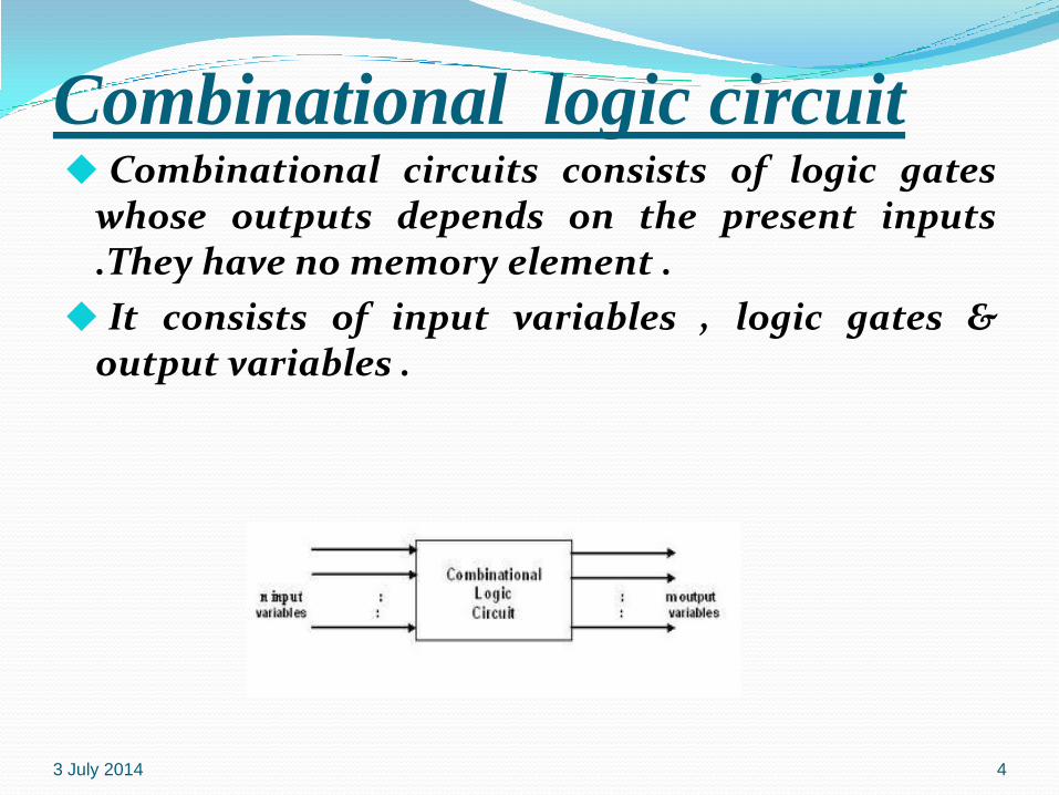
Combinational logic circuit Combinational circuits consists of logic gates
whose outputs depends on the present inputs.They have no memory element .
It consists of input variables , logic gates &output variables .
3 July 2014 4
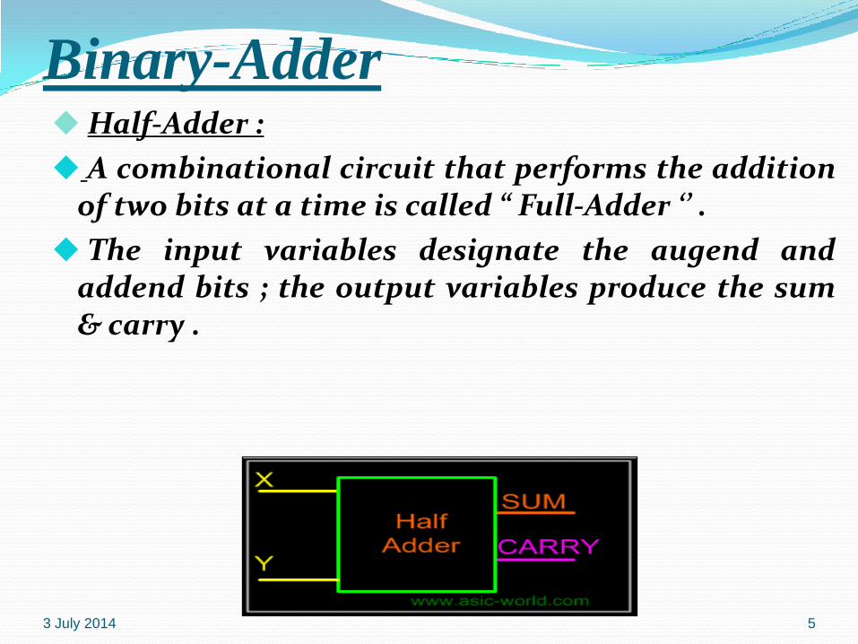
Binary-AdderHalf-Adder :
A combinational circuit that performs the additionof two bits at a time is called “ Full-Adder ‘’ .
The input variables designate the augend andaddend bits ; the output variables produce the sum& carry .
3 July 2014 5
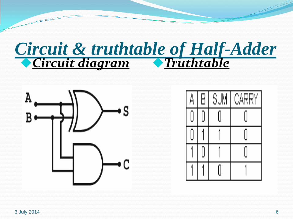
Circuit & truthtable of Half-AdderCircuit diagram Truthtable
3 July 2014 6
3 July 2014 7
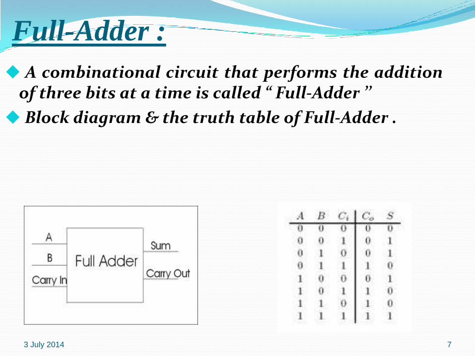
Full-Adder :
A combinational circuit that performs the additionof three bits at a time is called “ Full-Adder ’’
Block diagram & the truth table of Full-Adder .
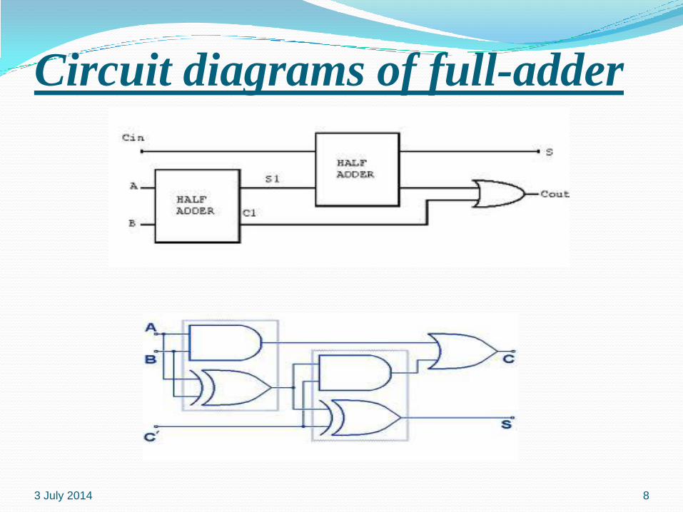
Circuit diagrams of full-adder
3 July 2014 8
Binary-Adder A Binary-Adder is a digital circuit that produces
the arthimatic sum of two binary numbers at atime .
It can also construct by cascading no of full-adders we get a N-bit binary-adder circuit .
An N-bit adder requires n full-adders with eachoutput carry connected to the input carry to thenext full-adder .
3 July 2014 9
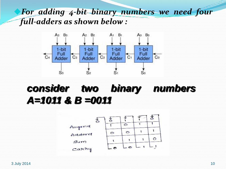
For adding 4-bit binary numbers we need fourfull-adders as shown below :
3 July 2014 10
consider two binary numbers
A=1011 & B =0011
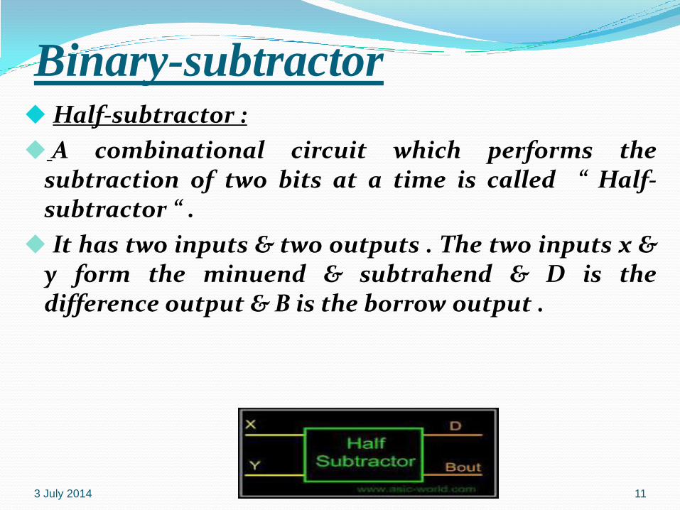
Binary-subtractorHalf-subtractor :
A combinational circuit which performs thesubtraction of two bits at a time is called “ Half-subtractor “ .
It has two inputs & two outputs . The two inputs x &y form the minuend & subtrahend & D is thedifference output & B is the borrow output .
3 July 2014 11
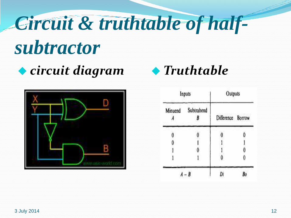
Circuit & truthtable of half-
subtractor circuit diagram Truthtable
3 July 2014 12
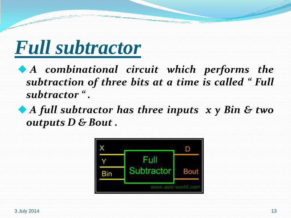
Full subtractor A combinational circuit which performs the
subtraction of three bits at a time is called “ Fullsubtractor “ .
A full subtractor has three inputs x y Bin & twooutputs D & Bout .
3 July 2014 13
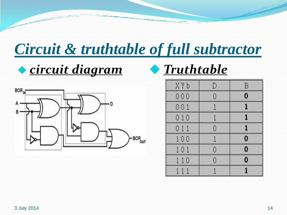
Circuit & truthtable of full subtractor
circuit diagram Truthtable
3 July 2014 14
Binary-subtractor The subtraction can be done by taking the 2’s
compliment of B and adding it to A .
2’s compliment can be obtained by taking the 1’scompliment and adding 1 to least significant bit .
1’s compliment can be obtained by changing 1’sinto 0’s & 0’s into 1’s .
3 July 2014 15
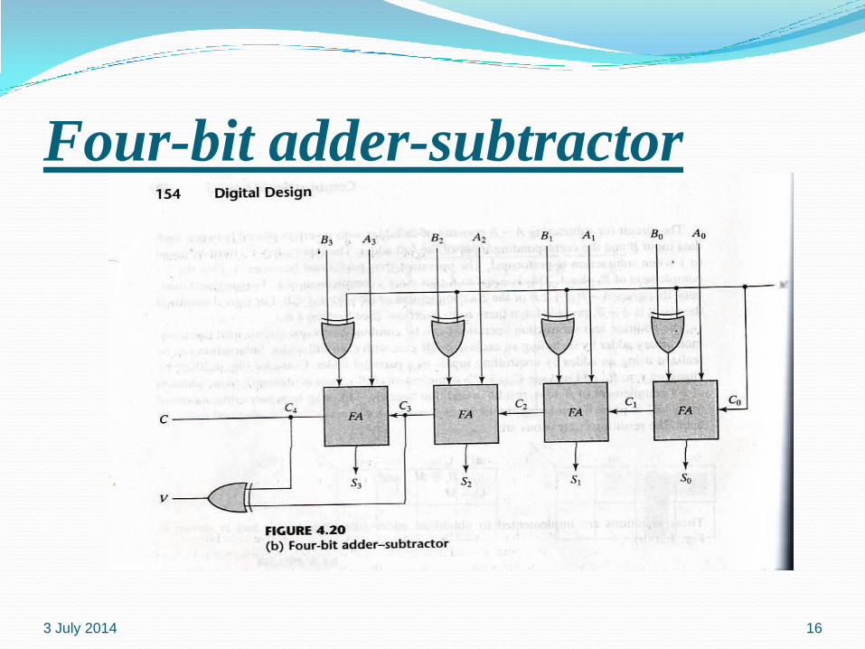
Four-bit adder-subtractor
3 July 2014 16
Continues…..
In this circuit the mode input m controls theoperation . When m=0 , the circuit is an addercircuit . When m=1, the circuit becomes asubtractor .
The c & v are two outputs . C is for carry & v is foroverflow . If v=0 after an addition or subtraction,then no overflow occurred and the n-bit result iscorrect . If v=1 , then the result of the operationcontains n+1 bits .
3 July 2014 17
Binary-multiplier
3 July 2014 18
The multiplication of binary numbers isperformed in the same way as multiplication ofdecimal numbers .
If we take the multiplication of 2-bit numbers .The multiplicand bits are B1 & B0 , themultiplier bits are A1 & A0 and the product isC3,C2,C1,C0 .
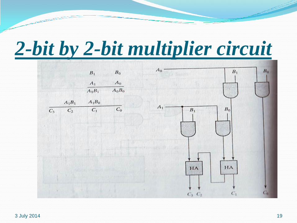
2-bit by 2-bit multiplier circuit
3 July 2014 19
Decoders A decoder is a combinational circuit that
converts binary information from n input lines toa maximum of 2n unique output lines .
Generally a decoder is called as n to m linedecoder .
A decoder is used to convert binary form to anyother desired form .
3 July 2014 20
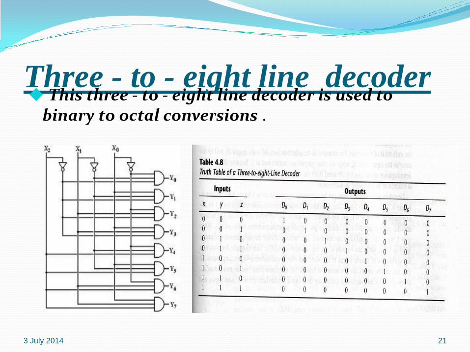
Three - to - eight line decoder This three - to - eight line decoder is used to
binary to octal conversions .
3 July 2014 21
Multiplexermultiplexer is a combinational circuit that
selects binary information from one of manyinput lines and directs it to a single output line .
Normally there are 2n input lines and n selectionlines whose bit combinations determines whichinput is selected .
A multiplexer is also called ‘ Data selector ’
3 July 2014 22
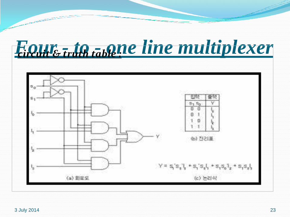
Four - to - one line multiplexercircuit & truth table :
3 July 2014 23

THANK YOU3 July 2014 24