49th ICFA Advanced Beam Dynamics Workshop Electron cloud Induced Instabilities… · 2010-10-13 ·...
31
49th ICFA Advanced Beam Dynamics Workshop Electron cloud Induced Instabilities, Non-Linear Beam Dynamics, and Emittance Growth G. Dugan, Cornell University ECLOUD’10 WORKSHOP 10/8/10 10/13/2010
Transcript of 49th ICFA Advanced Beam Dynamics Workshop Electron cloud Induced Instabilities… · 2010-10-13 ·...

49th ICFA Advanced Beam Dynamics Workshop
Electron cloud Induced Instabilities, Non-Linear
Beam Dynamics, and Emittance Growth
G. Dugan, Cornell University
ECLOUD’10 WORKSHOP
10/8/10
10/13/2010

49th ICFA Advanced Beam Dynamics Workshop
Electron clouds and particle beams
• You have heard about how electron clouds are formed and can
build up in the vacuum chambers of accelerators.
• The high-energy particle beam in the accelerator has to share
the “vacuum” chamber with the electron cloud, and does not
like it.
• Note that the dominant effects are present for positively
charged beams (e.g., protons, positrons), since in these cases
10/13/2010
charged beams (e.g., protons, positrons), since in these cases
the beam attracts the electron cloud and can be strongly
influenced by it.
• In this talk, we will discuss the effects that electron clouds can
have on the dynamics of particle beams in accelerators. The
emphasis will be on positron beams and experiments at CESR.

49th ICFA Advanced Beam Dynamics Workshop
Accelerators
• An accelerator is a device used to produce a beam of
high-energy particles
September 24, 2010 ECLOUD`10 - Cornell University 3

49th ICFA Advanced Beam Dynamics Workshop
Cornell Electron Storage Ring
• The Cornell Electron Storage Ring (CESR) is a circular
accelerator of a type called a “synchrotron”.
• The particles in the beam (positrons) travel at very close to
light speed in roughly circular orbits of circumference about
760 m. •The bending magnets
(dipoles) provide the
bending needed for a
circular orbits.
•The focusing magnets
September 24, 2010 ECLOUD`10 - Cornell University 4
•The focusing magnets
(quadrupoles) provide the
restoring forces needed for
stable oscillations.
•The RF cavity provides
energy to the beam.

49th ICFA Advanced Beam Dynamics Workshop
Particle beam oscillations
• The particles in the beam (positrons), traveling in
approximately plane circular orbits within a vacuum chamber,
execute small-amplitude oscillations about the plane:
Circular orbit (~ 760 m in CESR)
Beam particle
10/13/2010
Circular orbit (~ 760 m in CESR)
Oscillation (amplitude << 1 mm)
In the accelerator, the focusing forces which provide the
stability for the oscillations are provided by the quadrupole
magnets, arranged in a “lattice”.
Vacuum chamber not shown
49th ICFA Advanced Beam Dynamics Workshop
Particle beam dynamics
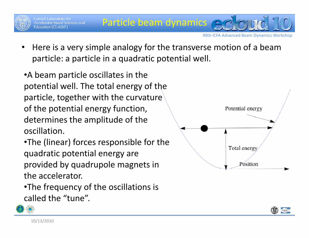
• Here is a very simple analogy for the transverse motion of a beam
particle: a particle in a quadratic potential well.
•A beam particle oscillates in the
potential well. The total energy of the
particle, together with the curvature
of the potential energy function,
determines the amplitude of the
10/13/2010
determines the amplitude of the
oscillation.
•The (linear) forces responsible for the
quadratic potential energy are
provided by quadrupole magnets in
the accelerator.
•The frequency of the oscillations is
called the “tune”.

49th ICFA Advanced Beam Dynamics Workshop
Phase space and emittance
• A plot of the position vs. velocity of the particle as measured at some
point in the ring, on subsequent turns, is called a “phase space” plot.
• Over many cycles of the oscillation, if the forces are linear, the particle
will trace out an ellipse in phase space.
• The area contained within the ellipse is related to the amplitude of
the oscillations, and is called the “emittance”.
• At different points in the ring, the orientation and shape of the ellipse
will be different, but the area will always be the same. will be different, but the area will always be the same.
September 24, 2010 ECLOUD`10 - Cornell University 7
Dots represent the position and velocity
of a beam particle at point A in the ring,
on each turn
Area=emittance
A
Beam particlePhase plot
at point A

49th ICFA Advanced Beam Dynamics Workshop
Beam quality: emittance
• When we have a collection of beam particles with different emittances in the accelerator, the projection of the collection’s points onto the position axis is the beam position distribution at that point in the ring. It is determined by the average emittance.
• For many applications, the beam
Phase plot
at point A
• For many applications, the beam size should be kept as small as possible: hence the average emittance should be as low as possible.
• The most important reason to control the electron cloud in accelerators is to prevent any growth in the emittance.
10/13/2010
Beam size at point A
Beam distribution
at point A
49th ICFA Advanced Beam Dynamics Workshop
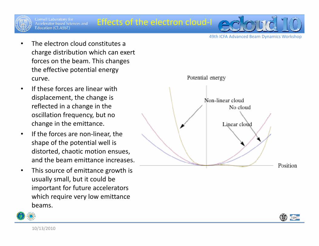
Effects of the electron cloud-I
• The electron cloud constitutes a
charge distribution which can exert
forces on the beam. This changes
the effective potential energy
curve.
• If these forces are linear with
displacement, the change is
reflected in a change in the
oscillation frequency, but no
change in the emittance. change in the emittance.
• If the forces are non-linear, the
shape of the potential well is
distorted, chaotic motion ensues,
and the beam emittance increases.
• This source of emittance growth is
usually small, but it could be
important for future accelerators
which require very low emittance
beams.
10/13/2010

49th ICFA Advanced Beam Dynamics Workshop
Effects of the electron cloud-II
•The electron cloud can move under
the influence of the fields of the beam,
so that the beam and the cloud
interact dynamically.
•The beam-cloud interaction will result
in each system undergoing oscillations
driven by the other system.
• If this mutual interaction is strong
10/13/2010
• If this mutual interaction is strong
enough, unstable motion of the beam
can result, increasing its emittance and
possibly even driving it into the
vacuum chamber walls.
•In plasma physics terminology, this is
called a “two-stream instability”.

49th ICFA Advanced Beam Dynamics Workshop
Effects of the electron cloud
Summarizing the effects of the electron cloud on the beam:
1. At low cloud densities, the linear forces exerted by the cloud change the
oscillation frequency (tune) of the beam.
2. At higher densities, the smaller non-linear forces can cause chaotic motion of
the beam particles, leading to growth in the emittance (and size) of the beam.
3. At still higher densities, the mutual dynamic interaction between the beam
and the cloud can cause the beam’s motion to become unstable, leading to very
large growth in the emittance and possibly also loss of the beam from the
10/13/2010
large growth in the emittance and possibly also loss of the beam from the
vacuum chamber.
• Effect 2 can be observed by precise measurements of the beam size in the
presence of the cloud.
• We will look a little more closely at effects 1 and 3, and how they can be
measured in CESR-TA.

49th ICFA Advanced Beam Dynamics Workshop
Bunches and trains
• It is important to understand how the beam is
“formatted” in CESR.
• The circulating beam is a string of “bunches”
which form a “train”. Each bunch is a collection
of around 1010 beam particles. The length of a
bunch is about 2 cm (~ 0.1 x 10⁻⁹ s), and they are
typically separated by about 4.2 m (14 x 10-9 s).
• The bunches can be “loaded” to form trains of
Bunch length
•from 1 to ~ 500 bunches.
• In a given experiment, the number of particles in
a bunch, the bunch spacing, and the number of
bunches in a train can be varied.
• In the experiments I will describe at CESR, the
length of the train is much less than the
circumference, so there is a big “gap” after each
train.
10/13/2010
Bunches in the train
z
49th ICFA Advanced Beam Dynamics Workshop
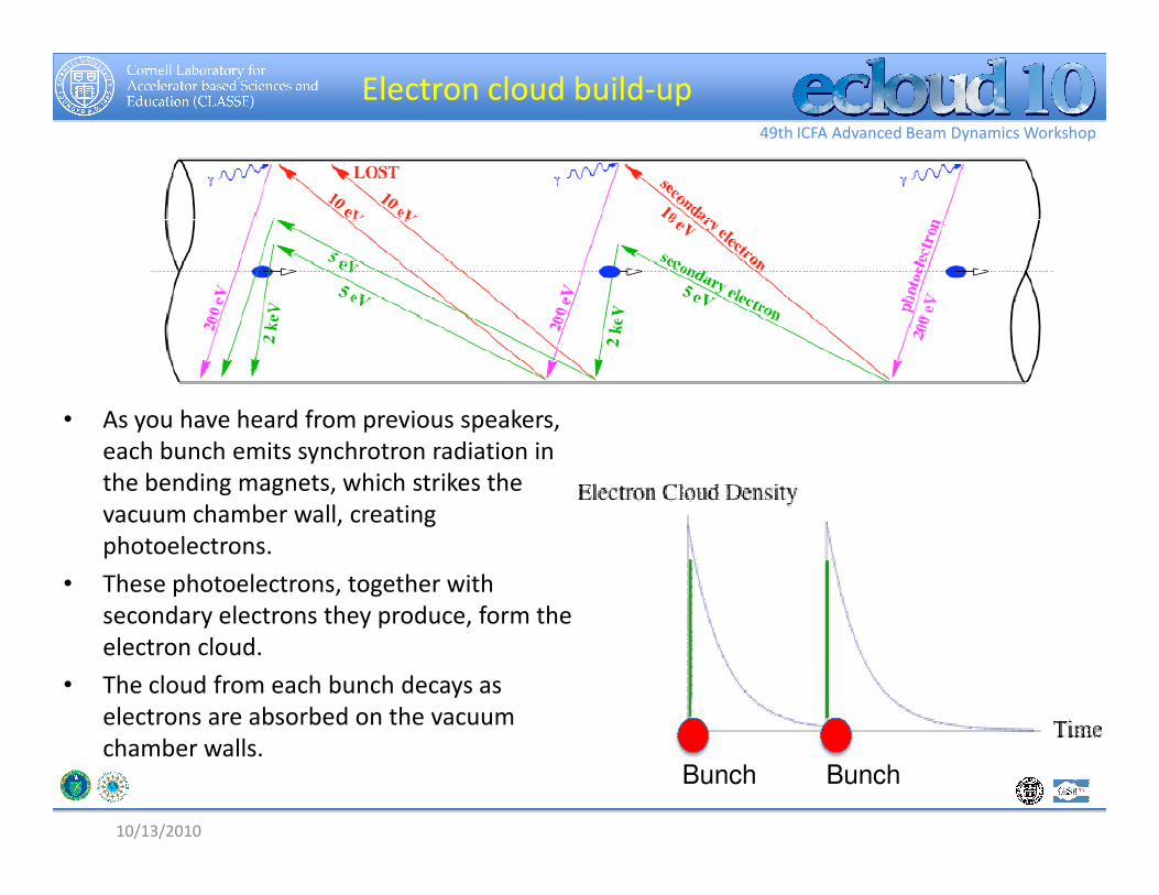
Electron cloud build-up
• As you have heard from previous speakers,
each bunch emits synchrotron radiation in each bunch emits synchrotron radiation in
the bending magnets, which strikes the
vacuum chamber wall, creating
photoelectrons.
• These photoelectrons, together with
secondary electrons they produce, form the
electron cloud.
• The cloud from each bunch decays as
electrons are absorbed on the vacuum
chamber walls.
10/13/2010
Bunch Bunch

49th ICFA Advanced Beam Dynamics Workshop
Electron cloud build-up
• If the bunches are closer
together than the cloud decay
time, the electron cloud builds
up along the train, so that
each later bunch in the train
sees the electron cloud
generated by previous Bunches
generated by previous
bunches.
• Hence the effects of the cloud
on the beam are greater for
bunches later in the train,
than for earlier bunches.
10/13/2010
• The change in oscillation
frequency (“tune shift”) due
to the electron cloud is
related to the cloud density,
and it will increase for each
later bunch in the train.
Bunches
49th ICFA Advanced Beam Dynamics Workshop
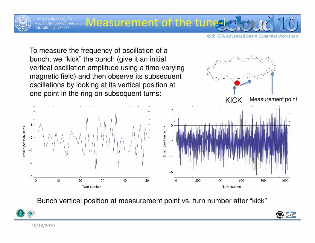
Measurement of the tune-I
To measure the frequency of oscillation of a
bunch, we “kick” the bunch (give it an initial
vertical oscillation amplitude using a time-varying
magnetic field) and then observe its subsequent
oscillations by looking at its vertical position at
one point in the ring on subsequent turns:Measurement pointKICK
10/13/2010
Bunch vertical position at measurement point vs. turn number after “kick”

49th ICFA Advanced Beam Dynamics Workshop
Measurement of the tune-II
We then Fourier analyze the motion to extract the characteristic
oscillation frequency:
Vertical oscillation frequency
10/13/2010
We do this for each bunch in the train. The change in frequency along
the train is due in part to the influence of the electron cloud’s electric
fields, which are building up during the train.

49th ICFA Advanced Beam Dynamics Workshop
Cloud buildup along a train at CesrTA
The electron cloud builds up during a 45-bunch train, resulting in an
increase in the vertical oscillation frequency with bunch number. We can
compare the data (black) with a calculation (red) from an electron cloud
simulation program (POSINST).
Electron cloud builds up during
the train

49th ICFA Advanced Beam Dynamics Workshop
A 21 bunch train, followed by witnesses
SEY=2.0SEY=.2.2SEY=1.8
Electron cloud decay
Electron cloud builds up during the train
Electron cloud decay
after the train is
measured using “witness
bunches” placed at
different times after the
train, to probe the cloud
at that time.
49th ICFA Advanced Beam Dynamics Workshop
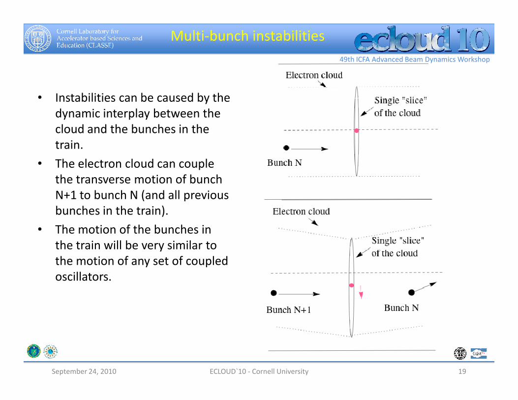
Multi-bunch instabilities
• Instabilities can be caused by the
dynamic interplay between the
cloud and the bunches in the
train.
• The electron cloud can couple
the transverse motion of bunch
N+1 to bunch N (and all previous N+1 to bunch N (and all previous
bunches in the train).
• The motion of the bunches in
the train will be very similar to
the motion of any set of coupled
oscillators.
September 24, 2010 19ECLOUD`10 - Cornell University

49th ICFA Advanced Beam Dynamics Workshop
Normal modes for 2 bunches
• For the simplest case of two
evenly-spaced bunches in the
ring, there will be two normal
modes of oscillation: the
“m=0” mode in which the two
bunches oscillate in phase,
and the “m=1” mode in which
the two bunches oscillate out
of phase.
m=0
September 24, 2010 ECLOUD`10 - Cornell University 20
of phase.
• Each mode will have a
specific frequency,
determined in part by the
electron cloud’s electric fields.
• Depending on the relative
phase of the bunches and the
oscillating electron cloud, one
or both of the modes may be
unstable.
m=1

49th ICFA Advanced Beam Dynamics Workshop
-Example of a multi-bunch instability
Here is an example of a calculation of an electron-cloud driven
horizontal multi-bunch instability in Cesr-TA.
The estimate is done for a train of 63 bunches with 42 ns
spacing, 0.5 mA/bunch, positrons.
The most unstable mode has a growth time of about 8.5 ms.
10/13/2010
Horizontal growth rate vs. mode numberSnapshot of the most unstable mode

49th ICFA Advanced Beam Dynamics Workshop
Single-bunch instabilities-I
• To control instabilities, we can use feedback systems, in which we
detect the motion of each bunch and apply a “kick” to cancel out
the detected motion.
• Multi-bunch instabilities have a growth time which is low enough
that they can typically be stabilized by state-of-the-art transverse
feedback systems.
• For this reason, they are not a major concern.• For this reason, they are not a major concern.
• However, the electron cloud can also give rise to single-bunch
instabilities, which occur within a single bunch.
• In positron storage rings, the short bunches mean that these
instabilities have a very high frequency spectrum, with rapid
growth times, and typically cannot be controlled by conventional
feedback.
September 24, 2010 ECLOUD`10 - Cornell University 22

49th ICFA Advanced Beam Dynamics Workshop
Single-bunch instabilities-II
• In a single-bunch instability, the electron
cloud couples the motion of the “head” of
the bunch with the “tail”.
• A unique feature of this interaction is that
the “head” of the bunch “pinches” the cloud
due to the attraction between the beam and
the cloud.
• The “tail” then gets a much stronger kick
than the “head”.
Bunch length
HEADTAIL
Direction
of motion
than the “head”.
September 24, 2010 23ECLOUD`10 - Cornell University

49th ICFA Advanced Beam Dynamics Workshop
Cloud pinch
Here is a result from a
cloud simulation
program (POSINST)
showing the increase
in cloud density
during the passage of
bunch 17 (in a 20
bunch train) through a
slice of the cloud.
TAILHEAD
Beam number density
Electron cloud density near the beam
September 24, 2010 ECLOUD`10 - Cornell University 24
•Thus the tail of the bunch can be driven by motion of the head, amplified
by the “pinched” electron cloud.
•Since the tail and head have the same vertical oscillation frequency, the
tail is driven on resonance and a large amplitude could be expected to
develop rapidly.
•However, in a circular machine, the beam particles in the head and the tail
exchange places due to their synchrotron motion.

49th ICFA Advanced Beam Dynamics Workshop
Synchrotron motion
• The beam particles have a range of beam
energies typically ~ 0.1% about the mean
energy.
• The transit time of a beam particle around
the ring depends on its energy.
• The radiofrequency (RF) cavities in the ring
provide a time-dependent energy gain or
loss which results in stable oscillations of
energy of each particle about the mean
Energy-
time phase
space
TAIL
HEAD
energy of each particle about the mean
energy of the beam. The frequency of these
oscillations is called the “synchrotron
frequency”.
• The dependence of the transit time on
energy and the energy oscillation results in
the exchange of particles between the head
and the tail at twice the synchrotron
frequency.
September 24, 2010 ECLOUD`10 - Cornell University 25
HEAD
TAIL
After ½ of a
synchrotron
period

49th ICFA Advanced Beam Dynamics Workshop
Head-tail modes
• The head-tail exchange tends to
stabilize the motion, especially if
the tune also has some
dependence on the energy
(“chromaticity”), but with
sufficiently high density clouds,
instability can still occur.
• The head and tail motion is
m=0
• The head and tail motion is
described in terms of normal
modes, just as for two bunches.
In one mode, the head and tail
are in-phase; in the other mode,
they are out-of-phase.
• One or both of the normal
modes may be unstable.
September 24, 2010 ECLOUD`10 - Cornell University 26
m=1
49th ICFA Advanced Beam Dynamics Workshop
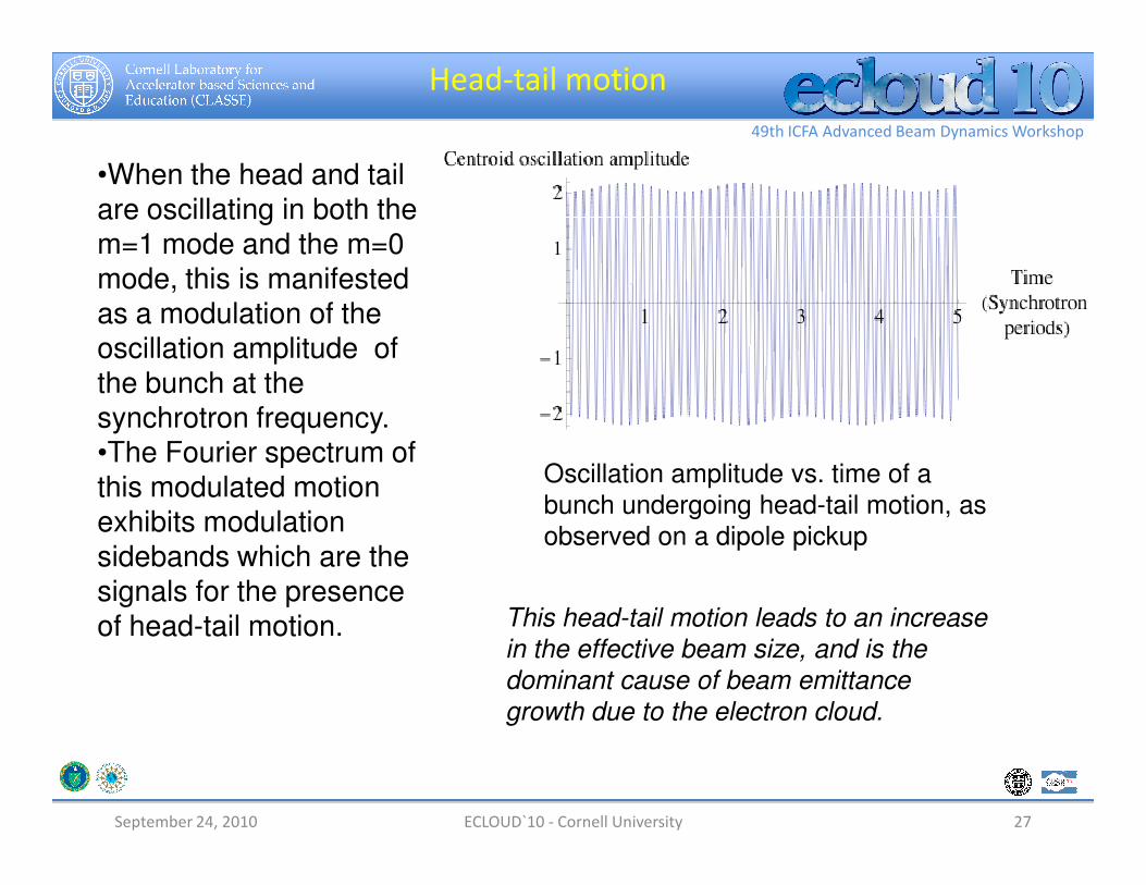
Head-tail motion
•When the head and tail are oscillating in both the m=1 mode and the m=0 mode, this is manifested as a modulation of the oscillation amplitude of the bunch at the synchrotron frequency. •The Fourier spectrum of
September 24, 2010 ECLOUD`10 - Cornell University 27
•The Fourier spectrum of this modulated motion exhibits modulation sidebands which are the signals for the presence of head-tail motion.
Oscillation amplitude vs. time of a
bunch undergoing head-tail motion, as
observed on a dipole pickup
This head-tail motion leads to an increase
in the effective beam size, and is the
dominant cause of beam emittance
growth due to the electron cloud.

49th ICFA Advanced Beam Dynamics Workshop
Synchrotron sidebands
• Fourier spectrum of a bunch undergoing head-tail motion
Spectral line due to vertical oscillation;
frequency ~ 222 kHz
Synchrotron frequency ~ 25 kHz Synchrotron
(modulation)
sideband
September 24, 2010 ECLOUD`10 - Cornell University 28
sideband

49th ICFA Advanced Beam Dynamics Workshop
When the electron cloud induces head-tail motion, we see the appearance and
subsequent growth of these modulation sidebands along the bunch train
Synchrotron sideband growth along the
train
Beam size
growth is
also
observed,
typically
coincident
with the
sidebands.
10/13/2010

49th ICFA Advanced Beam Dynamics Workshop
• At low cloud densities, the linear forces exerted by the electron
cloud change the oscillation frequency (tune) of the beam. We
can use the measured tune shifts to test models which predict the
growth of the electron cloud.
• At higher cloud densities, the smaller non-linear forces can cause
chaotic motion of the beam particles, leading to growth in the
emittance of the beam. This emittance growth may be small, but
Conclusions - I
September 24, 2010 ECLOUD`10 - Cornell University 30
emittance of the beam. This emittance growth may be small, but
could be important for future accelerators which require very low
emittance beams.
•At still higher densities, the mutual dynamic interaction between
the beam and the cloud can cause the beam’s motion to become
unstable, leading to very large growth in the emittance and
possibly also loss of the beam from the vacuum chamber.

49th ICFA Advanced Beam Dynamics Workshop
• Instabilities can involve the coupling of one bunch in a train to the
other (multi-bunch instabilities), or the coupling of particles in the tail
of one bunch to those in the head of the same bunch (single-bunch
instabilities). Both varieties will be produced by the electron cloud.
• Multi-bunch instabilities typically have slow growth times and can be
controlled by conventional beam feedback systems.
• Single-bunch instabilities are more dangerous and not easily
controllable. They can lead to rapid emittance growth.
Conclusions
September 24, 2010 ECLOUD`10 - Cornell University 31
controllable. They can lead to rapid emittance growth.
• In the design of measures to mitigate the development of the
electron cloud in existing or future accelerators, the design
requirement usually taken is to be below the threshold for the onset
of single-bunch instabilities.
• In some future machines, non-linear emittance growth may also be
important. This is a subject of active study.