49th CIRP Conference on Manufacturing Systems (CIRP-CMS ... · 49th CIRP Conference on...
6
Available online at www.sciencedirect.com Procedia CIRP 00 (2016) 000–000 www.elsevier.com/locate/procedia 49th CIRP Conference on Manufacturing Systems (CIRP-CMS 2016) A systematic approach to OPC UA information model design Florian Pauker a,* , Thomas Fr ¨ uhwirth b , Burkhard Kittl a , Wolfgang Kastner b a Institute for Production Engineering and Laser Technology - TU Wien, Karlsplatz 13, 1040 Vienna, Austria b Institute of Computer Aided Automation - TU Wien, Karlsplatz 13, 1040 Vienna, Austria * Florian Pauker. Tel.: +43-158801-311-382; Fax: +43-158801-311-99; E-mail address: [email protected] Abstract Current trends in manufacturing focus on the use of Information and Communication Technologies (ICT). The physical world and its virtual representation are increasingly converging, which leads to Cyber-Physical Production Systems (CPPS) in the manufacturing environment. CPPS synergize conventional production technology as well as ICT, allowing machines and products to exchange information, trigger actions and control other components autonomously. Therefore, seamless communication between physical objects of the shop floor and various computer systems is required. The Reference Architecture Model Industrie 4.0 (RAMI4.0) provided by the Plattform Industrie 4.0 specifies requirements for CPPS consisting of Industrie 4.0-components. In such systems, a major goal is to enable communication of I4.0 components among each other via industrial networks. For this purpose, RAMI4.0 suggests that each component has a virtual representation and uses Service-Oriented Architecture (SOA) based communication with I4.0-semantics. This paper describes a systematic approach to OPC Unified Architecture (OPC UA) information model for representing the static and dynamic behavior of manufacturing systems. Moreover, the approach is generic in the sense that it can be used to define information models for multiple target technologies, such as OPC UA, MTConnect and others. It even allows to reuse large parts of the generated models for similar manufacturing utilities and various target technologies. Therefore, we first present a concept for system analysis and design by using the Unified Modeling Language (UML), which is widely accepted for interdisciplinary work. The information gathered is then transformed to OPC UA information models which serves as target technology in this paper. The purpose of this approach is to simplify the process of defining virtual representations of manufacturing systems. Applying the presented concept allows transformation of classic manufacturing systems into CPPS with SOA-based communication and semantically rich virtual representations of individual components. It is therefore well suited to meet the requirements specified by RAMI4.0. c 2016 The Authors. Published by Elsevier B.V. Peer-review under responsibility of Scientific committee of the 49th CIRP Conference on Manufacturing Systems (CIRP-CMS 2016). Keywords: OPC UA; MDA; CPPS; SOA; information model; RAMI4.0; virtual representation 1. Introduction Current manufacturing systems are faced with increasing use of Information and Communication Technologies (ICT). One of the most significant developments in that field are Cyber- Physical Systems (CPS). CPS are a new generation of sys- tems with integrated computational and physical capabilities [1]. They are characterized by a combination of real (physical) objects with information processing (virtual) objects which can communicate via (industrial) communication networks [2]. The introduction of CPS into the manufacturing environ- ment leads to Cyber-Physical Production Systems (CPPS). CPPS synergize conventional production technology and ICT, allowing machines and products to exchange information, trig- ger actions and control other components autonomously. This includes information exchange across all levels of production, from sensor to processes through machines up to production and logistics networks [3]. Several R&D topics arise from the design and implemen- tation of CPPS. The most important ones are to create stan- dardized interfaces for vertical and horizontal data exchange through value added networks and define the ”virtual twin” (i.e., the virtual representation of a physical object) of a man- ufacturing system. To realize the idea of flexible production systems, new methods are required which support the fusion of the virtual and real sub-systems. These methods have to be robust and fit for the future to be useful in rapid changing environments, such as modern production facilities. [4]. The Reference Architecture Model Industrie 4.0 (RAMI4.0) [5] pro- vided by the Platform Industrie 4.0 offers solutions to the pre- viously named challenges. It defines a Reference Architecture Model, which precisely describes Industrie 4.0 compliant pro- duction equipment. In addition, RAMI4.0 describes future pro- duction networks consisting of Industrie 4.0 components (I4.0- components). These I4.0-components have Service-Oriented Architecture (SOA) communication capabilities and a virtual 2212-8271 c 2016 The Authors. Published by Elsevier B.V. Peer-review under responsibility of Scientific committee of the 49th CIRP Conference on Manufacturing Systems (CIRP-CMS 2016).
Transcript of 49th CIRP Conference on Manufacturing Systems (CIRP-CMS ... · 49th CIRP Conference on...

Available online at www.sciencedirect.com
Procedia CIRP 00 (2016) 000–000www.elsevier.com/locate/procedia
49th CIRP Conference on Manufacturing Systems (CIRP-CMS 2016)
A systematic approach to OPC UA information model designFlorian Paukera,*, Thomas Fruhwirthb, Burkhard Kittla, Wolfgang Kastnerb
aInstitute for Production Engineering and Laser Technology - TU Wien, Karlsplatz 13, 1040 Vienna, AustriabInstitute of Computer Aided Automation - TU Wien, Karlsplatz 13, 1040 Vienna, Austria
∗ Florian Pauker. Tel.: +43-158801-311-382; Fax: +43-158801-311-99; E-mail address: [email protected]
Abstract
Current trends in manufacturing focus on the use of Information and Communication Technologies (ICT). The physical world and its virtualrepresentation are increasingly converging, which leads to Cyber-Physical Production Systems (CPPS) in the manufacturing environment. CPPSsynergize conventional production technology as well as ICT, allowing machines and products to exchange information, trigger actions andcontrol other components autonomously. Therefore, seamless communication between physical objects of the shop floor and various computersystems is required. The Reference Architecture Model Industrie 4.0 (RAMI4.0) provided by the Plattform Industrie 4.0 specifies requirementsfor CPPS consisting of Industrie 4.0-components. In such systems, a major goal is to enable communication of I4.0 components among eachother via industrial networks. For this purpose, RAMI4.0 suggests that each component has a virtual representation and uses Service-OrientedArchitecture (SOA) based communication with I4.0-semantics. This paper describes a systematic approach to OPC Unified Architecture (OPCUA) information model for representing the static and dynamic behavior of manufacturing systems. Moreover, the approach is generic in the sensethat it can be used to define information models for multiple target technologies, such as OPC UA, MTConnect and others. It even allows to reuselarge parts of the generated models for similar manufacturing utilities and various target technologies. Therefore, we first present a concept forsystem analysis and design by using the Unified Modeling Language (UML), which is widely accepted for interdisciplinary work. The informationgathered is then transformed to OPC UA information models which serves as target technology in this paper. The purpose of this approach is tosimplify the process of defining virtual representations of manufacturing systems. Applying the presented concept allows transformation of classicmanufacturing systems into CPPS with SOA-based communication and semantically rich virtual representations of individual components. It istherefore well suited to meet the requirements specified by RAMI4.0.c© 2016 The Authors. Published by Elsevier B.V.Peer-review under responsibility of Scientific committee of the 49th CIRP Conference on Manufacturing Systems (CIRP-CMS 2016).
Keywords: OPC UA; MDA; CPPS; SOA; information model; RAMI4.0; virtual representation
1. Introduction
Current manufacturing systems are faced with increasing useof Information and Communication Technologies (ICT). Oneof the most significant developments in that field are Cyber-Physical Systems (CPS). CPS are a new generation of sys-tems with integrated computational and physical capabilities[1]. They are characterized by a combination of real (physical)objects with information processing (virtual) objects which cancommunicate via (industrial) communication networks [2].
The introduction of CPS into the manufacturing environ-ment leads to Cyber-Physical Production Systems (CPPS).CPPS synergize conventional production technology and ICT,allowing machines and products to exchange information, trig-ger actions and control other components autonomously. Thisincludes information exchange across all levels of production,from sensor to processes through machines up to productionand logistics networks [3].
Several R&D topics arise from the design and implemen-tation of CPPS. The most important ones are to create stan-dardized interfaces for vertical and horizontal data exchangethrough value added networks and define the ”virtual twin”(i.e., the virtual representation of a physical object) of a man-ufacturing system. To realize the idea of flexible productionsystems, new methods are required which support the fusionof the virtual and real sub-systems. These methods have tobe robust and fit for the future to be useful in rapid changingenvironments, such as modern production facilities. [4]. TheReference Architecture Model Industrie 4.0 (RAMI4.0) [5] pro-vided by the Platform Industrie 4.0 offers solutions to the pre-viously named challenges. It defines a Reference ArchitectureModel, which precisely describes Industrie 4.0 compliant pro-duction equipment. In addition, RAMI4.0 describes future pro-duction networks consisting of Industrie 4.0 components (I4.0-components). These I4.0-components have Service-OrientedArchitecture (SOA) communication capabilities and a virtual
2212-8271 c© 2016 The Authors. Published by Elsevier B.V.Peer-review under responsibility of Scientific committee of the 49th CIRP Conference on Manufacturing Systems (CIRP-CMS 2016).

2 Florian Pauker / Procedia CIRP 00 (2016) 000–000
representation which adds semantic information to the physicalobject. Semantic describes the relation between signifiers (e.g.words) and their denotation, what they stand for.
This semantic is necessary, because the exchange of in-formation between two or more I4.0-components requires un-equivocal semantics. RAMI4.0 suggest OPC UA, because itcan be used for both, communication as well as to define vir-tual representations. OPC UA is the newest standard providedby the OPC Foundation, because of its communication capabil-ities.
In complex manufacturing systems several different entitiesare cooperating and each one needs a digital description (infor-mation model) in a semantic way.
While the Unified Modelling Language (UML) is estab-lished as the major modeling language in software develop-ment, there are several standards being used in the manufac-turing environment. For each of them, the model and the codemust be written and maintained separately, which requires highmanual effort.
Model-driven techniques, which are already used to designcomplex software systems tremendously simplify the processof information model design. The main concept of a model-driven approach is to separate the functional description andthe implementation [6]. Thus, it is not necessary to repeat theprocess of defining an application or the system’s functionalityand behavior each time a new communication technology (OPCUA, for example) comes along.
This paper describes a model driven approach to OPC UAinformation model design for the virtual representation of sys-tems. It thereby focuses on the manufacturing environment.The paper precisely specifies the workflow needed to generatethese virtual representations. This workflow briefly introducesthe necessary diagrams and tools for modeling and code gener-ation.
The remainder of the paper is structured as follows: Chap-ter 2 gives an introduction to the current standardization ef-forts, the ”RAMI4.0 ” (chapter 2.1). The connection betweenRAMI4.0 and OPC UA and UML is also described (Chapter2.2 & 2.3). Chapter 2.4 explains the basics of the MDA. Chap-ter 3 presents a model driven approach for OPC UA informa-tion model design. It describes all MDA phases in detail, in-cluding requirements analysis, platform independent modeling,platform specific modeling (OPC UA information modeling)and code generation. Chapter 4 summarizes the paper and givesan overview of the next steps to be done in the future.
2. State of the art and basic technologies
2.1. Reference Architecture Model RAMI4.0
The German Industrie 4.0 platform, consisting of Zentralver-band Elektrotechnik- und Elektronikindustrie e.V (ZVEI),Verband Deutscher Maschinen- und Anlagenbau (VDMA),and Bundesverband Informationswirtschaft, Telekommunika-tion und neue Medien (BITKOM), has published a first versionof a Reference Architecture Model for Industrie 4.0 (RAMI4.0)[5] which precisely describes Industrie 4.0-compliant produc-tion equipment.
RAMI4.0, consists of a three-dimensional coordinate systemthat describes all necessary aspects of Industrie 4.0.
The right horizontal axis shows the hierarchy levels knownfrom IEC 62264 [7] standard for enterprise IT and control sys-tems. These levels represent the different entities grouped bythe functionality which can be found in factories.
In addition to the hierarchical levels defined by IEC 62264,the layers labelled ”Product” representing a workiece and Con-nected World (the connection to the Internet of Things and In-ternet of Services) were defined to represent all hierarchical lev-els in an Industrie 4.0 environment.
Fig. 1. Reference Architecture Model RAMI4.0 [8]
On the left horizontal axis, the life cycle of facilities andproducts is shown. These different life cycle phases are basedon IEC 62890 for life-cycle management. The differnce be-tween instance and type are clearly described by RAMI4.0. Atype becomes an instance when the design and prototyping iscompleted and the product is ready for beeing manufactured.
The layers on the vertical axis describe the decompositionof a machine into its properties structured layer by layer. Theserepresentations originate from ICT, where properties of com-plex systems are usually broken down into layers.
Within these three axes, all crucial aspects of Industrie 4.0can be mapped, allowing objects such as machines to be classi-fied according to the model. Highly flexible Industrie 4.0 con-cepts can thus be described and implemented using RAMI4.0.
The reference architectural model allows for step-by-stepmigration from the present into the future world of Industrie4.0. Cross-vendor data exchange is necessary for communica-tion between machines or between machines and workpieces.This requires unified semantics including a common syntax fordata. RAMI4.0 proposes OPC UA for realizing such communi-cation.
2.2. OPC Unified Architecture - OPC UA
OPC Unified Architecture (OPC UA) [9] is the latest OPCstandard specification provided by the OPC Foundation. It isused for interconnectivity in state-of-the-art industrial automa-tion technology [10].
Classic OPC is implemented in almost all industrial automa-tion systems and, thus, well accepted. The three major improve-ments of the UA are platform independence, the capability toexchange data beyond local networks and the specification of ageneric information model, which is a basis for domain specific

Florian Pauker / Procedia CIRP 00 (2016) 000–000 3
information models [11]. Therefore it is widely accepted as anenabling technology for Industrie 4.0.
The OPC UA specification consists of 13 parts. The firstseven parts are related to the core specifications e.g. the con-cept, security model, address space model, services, informa-tion model, service mappings and profiles. The parts eight to
OPC UA Alarm and Conditions
(Part 9)
OPC UA Data Access
(Part 8)
OPC UA Programs (Part 10)
OPC UA Historical Access
(Part11)
Information models from other domains or organizations
Vendor-specfic, proprietary information models
OPC UA base information model (Part 5)
Fig. 2. OPC UA
thirteen are related to access type specifications like data ac-cess, alarms and conditions, programs, historical access, dis-covery and aggregates. The most important ones necessary foruser-specific information models are depicted in Fig. 2. Theaddress space model defined in Part 3 of the specification [12]is the meta model of OPC UA. The base component of the metamodel are nodes. Several node classes are defined specializingthe base node class (e.g. objects, variables, etc.). Each node hasa set of attributes depending on the node class. Some attributesare mandatory and some are optional. For example, each nodeclass requires a ”NodeId” uniquely identifying the node, whilethe ”Description” is optional [13].
Besides the communication part, data modeling is the sec-ond fundament of OPC UA. In [9], the base principals of UAmodeling are listed as follows:
• Using object-oriented techniques with type hierarchies andinheritance.• Type information is provided and can be accessed the same
way as an instance.• Full meshed network of nodes allows to connect the infor-
mation in different ways.• Extensibility of the type hierarchies as well as the refer-
ences types between nodes.• No limitations of modeling in order to allow an appropriate
information model design.• OPC UA information modeling is always done on the
server.
These principals allow to generate simple, but also very com-plex, OPC UA information models.
2.3. Unified Modeling Language - UML
The Unified Modeling Language (UML) specified by theObject Management Group (OMG), is a graphical language forvisualization, specification and documentation of artefacts ofsoftware systems [14]. UML is nowadays not only accepted asmajor modeling language for IT-software design, but is also of-ten used as a tool for interdisciplinary work. UML’s priority isto specify terms and relationships between them in form of socalled ”models” [15]. The latest specification, UML 2.5, hasmany types of diagrams which are broadly grouped into twocategories: structural and behavioral diagrams [16]. Behavioraldiagrams include dynamic diagrams, e.g. sequence diagram or
state-chart diagram, including a few that represent special as-pects of interactions. Structural diagrams like class diagrams,object diagrams, etc. are used to model static information.
To manage complexity, UML is organized into languageunits comprising a set of modeling elements [17]. The corelanguage units for the later described MDA approach are theclass, state-chart, component and use-case models.
2.4. Model-driven Architecture - MDA
In the Model-driven Architecture (MDA) models are thecentral elements of the software development process. Theaim is to derive platform-specific models from platform-independent models using a highly automated process. Thisreduces the effort of software development and the adaptationto new technologies [6]. Any additions and changes to themodel will be automatically reflected the next time the codeis generated. MDA models can then be used for the produc-tion of documentation, acquisition specifications, system speci-fications, technology artifacts (e.g. source code) and executablesystems [18]. Currently the main disadvantages of MDA is, thatavailable tools are not able to automatically generate 100% ofthe code. So there is always a need to adapt the code manuallyafter the generation process.
UML is the preferred modeling language for MDA. Themost important advantage of using UML for Model-driven-Architecture is that it proposes a format for information ex-change between tools and applications. Aside from UML,XML Metadata Interchange (XMI) [19] and the Meta-ObjectFacility (MOF) [20] are the most important standards related toMDA.
MDA defines three levels of abstraction. The ComputerIndependent Model (CIM), the Platform Independent Model(PIM) and the Platform Specific Model (PSM) [21].
A CIM is also often referred to as domain model because ituses a vocabulary that is familiar to the Subject Matter Experts(SMEs) [22]. It shows exactly what the system will do, butdo not respect technology-specific information, to remain in-dependent of the system implementation [23]. The CIM playsan important role to close the gap between domain experts andthe information technologists responsible for implementing thesystem [23].
A PIM specifies the system in more detail but still maintainsa sufficient degree of generality to allow its mapping to one ormore platforms. Usually this is done by defining a set of ser-vices, which do not consider technical details. The realizationof these services in a platform specific way is done with othermodels [23].
A PSM combines the specifications defined in the PIM withthe details required to stipulate how a system uses a particu-lar type of platform. The PSM has to contain all relevant in-formation, i.e. the static structure and dynamic behavior of thesystem, using different Domain Specific Languages (DSL). Au-tomated tools may be used to perform the PIM-PSM translation[21,23].
3. MDA approach to OPC UA information model design
The approach presented in this paper is depicted in Fig. 3.It offers a MDA based method using UML class, state-chart,
4 Florian Pauker / Procedia CIRP 00 (2016) 000–000
Platform Instance
MTConnect PSM
CIM
OPC UA PSM
R- PIM
dynamic system description
System analysis
User
Domain expert
know-how
know-how
Mapping
static system description
Information
MachineToolType
SafetyDoors :: FolderType
[Mandatory]
Organizes
ClampingSystems :: FolderType
[Mandatory]
Organizes
WorkingSpaceStateMachine :: FinateStateMachineType
SafetyDoor ::SafetyDoorType
[MandatoryPlaceholder]
ClampingSystem ::ClampingSystemType[OptionalPlaceholder]
OPC UA information model
Res
tric
ito
ns
Instantiation
Crea teO bjectSetti ng s setti ngs = new CreateObjectS ettings ()
{
ParentN odeId = O bj ec tI ds .O bj ec tsF older ,
ReferenceTypeId = ReferenceTypeIds.O rg aniz es,
RequestedN odeId = new N odeI d("Controllers", Insta nc eN am espa ceIndex),
BrowseN ame = new Q ual ifi edN ame ("Controllers", Insta nc eN am espa ceIndex),
TypeD efinitionId = O bj ec tTypeIds.FolderTy pe
};
Crea teO bject(Server.DefaultRequestContext, setti ng s);
// Crea te an Air Conditioner Controll er
setti ng s = new CreateObjectS ettings ()
{
ParentN odeId = new N odeI d("Controllers", Insta nc eN am espa ceIndex),
ReferenceTypeId = ReferenceTypeIds.O rg aniz es,
RequestedN odeId = new N odeI d("AirCondi ti oner1", Insta nc eN am espa ceIndex),
BrowseN ame = new Q ual ifi edN ame ("AirCondi ti oner1", Insta nc eN am espa ceIndex),
TypeD efinitionId = new N odeI d(yourorga ni sation.BA.O bj ec tTypes.AirCondi ti onerControllerTy pe ,
TypeN am espa ceIndex)
};
Crea teO bject(Server.DefaultRequestContext, setti ng s);
// Crea te a F urna ce Controller
setti ng s = new CreateObjectS ettings ()
{
ParentN odeId = new N odeI d("Controllers", Insta nc eN am espa ceIndex),
ReferenceTypeId = ReferenceTypeIds.O rg aniz es,
RequestedN odeId = new N odeI d("Furnac e1", Insta nc eN am espa ceIndex),
BrowseN ame = new Q ual ifi edN ame ("Furnac e1", Insta nc eN am espa ceIndex),
TypeD efinitionId = new N odeI d(yourorga ni sation.BA.O bj ec tTypes.Furnac eControl lerType, TypeN am espa ceIndex)
};
Crea teO bject(Server.DefaultRequestContext, setti ng s);
Generation
Release
Entity
OPC UA adress space model
Mo
del
to
Mo
del
Tran
sfo
rmat
ion
Manual instantiation
Man
ual
Tran
sfo
rmat
ion
UML-UseCase diagram
UML-Component diagram
Domain
UML-Classdiagram
UML-Statediagram
Info
rmat
ion
Code
Ontology
API
Fig. 3. MDA based workflow for OPC UA information model design
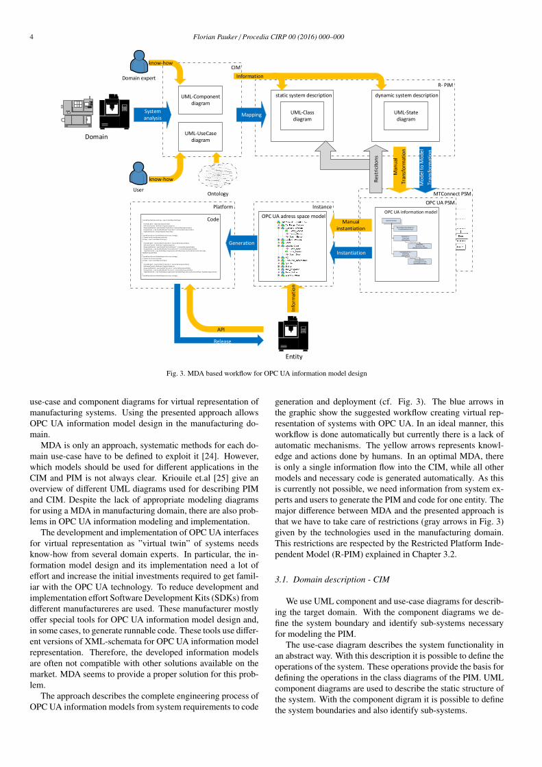
use-case and component diagrams for virtual representation ofmanufacturing systems. Using the presented approach allowsOPC UA information model design in the manufacturing do-main.
MDA is only an approach, systematic methods for each do-main use-case have to be defined to exploit it [24]. However,which models should be used for different applications in theCIM and PIM is not always clear. Kriouile et.al [25] give anoverview of different UML diagrams used for describing PIMand CIM. Despite the lack of appropriate modeling diagramsfor using a MDA in manufacturing domain, there are also prob-lems in OPC UA information modeling and implementation.
The development and implementation of OPC UA interfacesfor virtual representation as ”virtual twin” of systems needsknow-how from several domain experts. In particular, the in-formation model design and its implementation need a lot ofeffort and increase the initial investments required to get famil-iar with the OPC UA technology. To reduce development andimplementation effort Software Development Kits (SDKs) fromdifferent manufactureres are used. These manufacturer mostlyoffer special tools for OPC UA information model design and,in some cases, to generate runnable code. These tools use differ-ent versions of XML-schemata for OPC UA information modelrepresentation. Therefore, the developed information modelsare often not compatible with other solutions available on themarket. MDA seems to provide a proper solution for this prob-lem.
The approach describes the complete engineering process ofOPC UA information models from system requirements to code
generation and deployment (cf. Fig. 3). The blue arrows inthe graphic show the suggested workflow creating virtual rep-resentation of systems with OPC UA. In an ideal manner, thisworkflow is done automatically but currently there is a lack ofautomatic mechanisms. The yellow arrows represents knowl-edge and actions done by humans. In an optimal MDA, thereis only a single information flow into the CIM, while all othermodels and necessary code is generated automatically. As thisis currently not possible, we need information from system ex-perts and users to generate the PIM and code for one entity. Themajor difference between MDA and the presented approach isthat we have to take care of restrictions (gray arrows in Fig. 3)given by the technologies used in the manufacturing domain.This restrictions are respected by the Restricted Platform Inde-pendent Model (R-PIM) explained in Chapter 3.2.
3.1. Domain description - CIM
We use UML component and use-case diagrams for describ-ing the target domain. With the component diagrams we de-fine the system boundary and identify sub-systems necessaryfor modeling the PIM.
The use-case diagram describes the system functionality inan abstract way. With this description it is possible to define theoperations of the system. These operations provide the basis fordefining the operations in the class diagrams of the PIM. UMLcomponent diagrams are used to describe the static structure ofthe system. With the component digram it is possible to definethe system boundaries and also identify sub-systems.
Florian Pauker / Procedia CIRP 00 (2016) 000–000 5
In a subsequent step, the interfaces between the different sys-tems can be described in detail. The components defined in thediagram are the basis for the classes defined in the PIM.
The CIM to PIM transformation is currently done manuallyand requires additional knowledge from domain experts andsystem users (cf. Fig. 3).
3.2. Restricted platform independent description - R-PIM
The presented approach uses UML-class diagrams andUML-state charts to specify the dynamic behavior of manu-facturing systems. The main elements are classes with re-lated attributes and operations and the relationships betweenthe classes. To identify the classes, attributes and operationsnecessary for the UML class diagramm we use, in additionto the information defined in the CIM, object-oriented mod-eling methods such as Object-Oriented Software Engineering(OOSE) [26] or the Object Modeling Technique (OMT) [27].
Many manufacturing systems are event-driven, which meansthat they wait for the occurrence of some external or internalevents. After recognizing the event, such systems perform-ing the appropriate action, e.g. changing outputs or generatingother events that trigger internal software functions. With role-based scenarios, sub-systems are described and help to definethe dynamic behavior of the system with state diagrams. UMLstate charts are used to display these transitions from one stateto another. These diagrams consist of states, and transitionswith optional guards between them [28].
Established platform specific technologies (e.g. OPC UA,MTConnect) have been examined and a set of restrictions forplatform independent modeling were defined. These restric-tions lead to a R-PIM model which is not specialized for onlyone PSM, but with particular attention to OPC UA because ofits role in the current I4.0 initiatives. To model the restrictionsa meta-meta model may be used which is currently undefinedand has to be defined in future steps. A simple example for arestriction is given by multiple inheritances, which may be de-fined in UML. In C# or other implementing languages used inPSM multiple inheritances can not be implemented and so is arestriction for the R-PIM.
The R-PIM model is extended with additional informationneeded for the specific PSMs. This information transform theR-PIM into an annotated R-PIM. Each node in OPC UA hasthe mandatory attributes NodeId, NodeClass, BrowseName andDisplayName. Thus each class of the PIM is annotated withthese four parameters to meet the OPC UA requirements.
3.3. Transformation of R-PIM to PSM
Currently the transformation from UML to OPC UA is donemanually but there are already solutions available for automatedtransformation. Rohjans et al. [29] describe an automatic trans-formation of UML-class diagrams to OPC UA address spacemodels for power systems. They have developed a tool called”CIMBaT” [30] for automatic code design. This solution onlyallows to model the static behavior of the system.
A solution where the static structure as well as the dynamicbehavior of a system, including restrictions, can be describedand transformed into platform specific applications is currentlydeveloped at the TU Wien. For transformation of UML to OPCUA, transformation rules are required, which have been devel-
MTConnect
MTConnect PSM
R-PIM OPC UA PSM
M1Models
UML OPC UA
M2Meta
Models
MOFM3
Meta-Meta-Models
M0
Manufacturing System
CodeTransformation
.NETMapping Mapping
Transformation
Fig. 4. Transformation process PIM to PSM
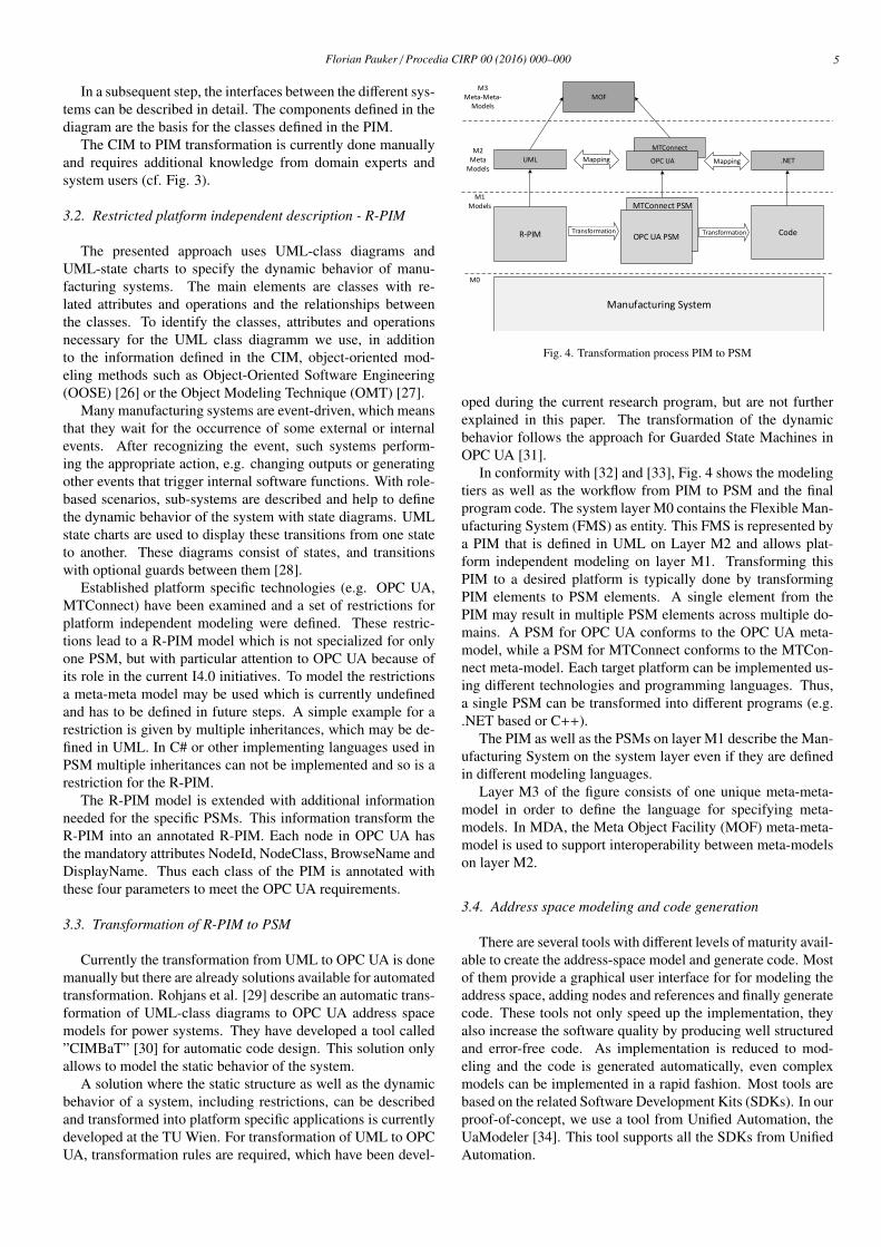
oped during the current research program, but are not furtherexplained in this paper. The transformation of the dynamicbehavior follows the approach for Guarded State Machines inOPC UA [31].
In conformity with [32] and [33], Fig. 4 shows the modelingtiers as well as the workflow from PIM to PSM and the finalprogram code. The system layer M0 contains the Flexible Man-ufacturing System (FMS) as entity. This FMS is represented bya PIM that is defined in UML on Layer M2 and allows plat-form independent modeling on layer M1. Transforming thisPIM to a desired platform is typically done by transformingPIM elements to PSM elements. A single element from thePIM may result in multiple PSM elements across multiple do-mains. A PSM for OPC UA conforms to the OPC UA meta-model, while a PSM for MTConnect conforms to the MTCon-nect meta-model. Each target platform can be implemented us-ing different technologies and programming languages. Thus,a single PSM can be transformed into different programs (e.g..NET based or C++).
The PIM as well as the PSMs on layer M1 describe the Man-ufacturing System on the system layer even if they are definedin different modeling languages.
Layer M3 of the figure consists of one unique meta-meta-model in order to define the language for specifying meta-models. In MDA, the Meta Object Facility (MOF) meta-meta-model is used to support interoperability between meta-modelson layer M2.
3.4. Address space modeling and code generation
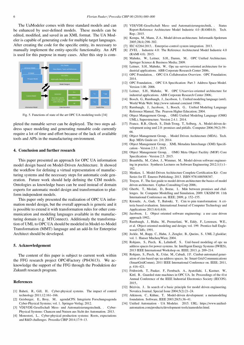
There are several tools with different levels of maturity avail-able to create the address-space model and generate code. Mostof them provide a graphical user interface for for modeling theaddress space, adding nodes and references and finally generatecode. These tools not only speed up the implementation, theyalso increase the software quality by producing well structuredand error-free code. As implementation is reduced to mod-eling and the code is generated automatically, even complexmodels can be implemented in a rapid fashion. Most tools arebased on the related Software Development Kits (SDKs). In ourproof-of-concept, we use a tool from Unified Automation, theUaModeler [34]. This tool supports all the SDKs from UnifiedAutomation.
6 Florian Pauker / Procedia CIRP 00 (2016) 000–000
The UaModeler comes with three standard models and canbe enhanced by user-defined models. These models can beedited, modified, and saved in an XML format. The UA Mod-eler is capable of generating code for multiple target languages.After creating the code for the specific entity, its necessary tomanually implement the entity-specific functionality. An APIis used for this purpose in many cases. After this step is com-
Information Model Source Files
*.c *.cpp
*.h *.cs
Code Generator
Generator
Generates code for custom models to be
used in the SDK
C++
ANSI C
C#
Model Designer
GUI, Display
View Objects, Types and References
GUI, Editor
Add/modify Objects, Types and References
Custom Model
UA Server Model
DI Model
PLCopen Model
Fig. 5. Functions of state of the art OPC UA modeling tools [34]
pleted the runnable server can be deployed. The two steps ad-dress space modeling and generating runnable code currentlyrequire a lot of time and effort because of the lack of availabletools and APIs in the manufacturing environment.
4. Conclusion and further research
This paper presented an approach for OPC UA informationmodel design based on Model-Driven Architecture. It showedthe workflow for defining a virtual representation of manufac-turing systems and the necessary steps for automatic code gen-eration. Future work should help defining the CIM models.Ontologies as knowledge bases can be used instead of domainexperts for automatic model design and transformation to plat-form independent models.
This paper only presented the realization of OPC UA infor-mation model design, but the overall approach is generic and itis possible to extend it with transformation rules for other com-munication and modeling languages available in the manufac-turing domain (e.g. MTConnect). Additionaly the transforma-tion of UML to OPC UA should be modeled in Model-to-ModelTransformation (MMT) language and an add-In for EnterpriseArchitect should be developed.
5. Acknowledgement
The content of this paper is subject to current work withinthe FFG research project OPC4Factory (P843613). We ac-knowledge the support of the FFG through the Produktion derZukunft research program.
References
[1] Baheti, R., Gill, H.. Cyber-physical systems. The impact of controltechnology 2011;12:161–166.
[2] Geisberger, E., Broy, M.. agendaCPS: Integrierte ForschungsagendaCyber-Physical Systems; vol. 1. Springer-Verlag; 2012.
[3] VDI/VDE-Gesellschaft Mess- und Automatisierungstechnik, . Cyber-Physical Systems: Chancen und Nutzen aus Sicht der Automation. 2013.
[4] Monostori, L.. Cyber-physical production systems: Roots, expectationsand R&D challenges. Procedia CIRP 2014;17:9–13.
[5] VDI/VDE-Gesellschaft Mess- und Automatisierungstechnik, . StatusReport-Reference Architecture Model Industrie 4.0 (RAMI4.0). Tech.Rep.; 2015.
[6] Kempa, M., Mann, Z.A.. Model driven architecture. Informatik-Spektrum2005;28(4):298–302.
[7] IEC 62264:2013, . Enterprise-control system integration. 2013.[8] ZVEI, . Industrie 4.0: The Reference Architectural Model Industrie 4.0
(RAMI 4.0). 2015.[9] Mahnke, W., Leitner, S.H., Damm, M.. OPC Unified Architecture.
Springer Science & Business Media; 2009.[10] Leitner, S.H., Mahnke, W.. Opc ua–service-oriented architecture for in-
dustrial applications. ABB Corporate Research Center 2006;.[11] OPC Foundation, . OPC-UA Collaboration Overview. OPC Foundation;
2014.[12] OPC Foundation, . OPC UA Specification: Part 3 Address Space Model.
Version 1.00. 2006.[13] Leitner, S.H., Mahnke, W.. OPC UAservice-oriented architecture for
industrial applications. ABB Corporate Research Center 2006;.[14] Booch, G., Rumbaugh, J., Jacobson, I.. Unified modeling language (uml).
World Wide Web: http://www rational com/uml 1998;.[15] Rumbaugh, J., Jacobson, I., Booch, G.. Unified Modeling Language
Reference Manual, The. Pearson Higher Education; 2004.[16] Object Management Group, . OMG Unified Modeling Language (OMG
UML), Superstructure. Version 2.4.1. 2014.[17] France, R.B., Ghosh, S., Dinh-Trong, T., Solberg, A.. Model-driven de-
velopment using uml 2.0: promises and pitfalls. Computer 2006;39(2):59–66.
[18] Object Management Group, . Model Driven Architecture (MDA). Tech.Rep. MDA Guide rev. 2.0; 2014.
[19] Object Management Group, . XML Metadata Interchange (XMI) Specifi-cation - Version 2.5.1. 2015.
[20] Object Management Group, . OMG Meta Object Facility (MOF) CoreSpecification - Version 2.5. 2015.
[21] Brambilla, M., Cabot, J., Wimmer, M.. Model-driven software engineer-ing in practice. Synthesis Lectures on Software Engineering 2012;1(1):1–182.
[22] Menken, I.. Model-Driven Architecture Complete Certification Kit - CoreSeries for IT. Emereo Publishing; 2013. ISBN 9781488508387.
[23] Truyen, F.. The fast guide to model driven architecture the basics of modeldriven architecture. Cephas Consulting Corp 2006;.
[24] Gherbi, T., Meslati, D., Borne, I.. Mde between promises and chal-lenges. In: Computer Modelling and Simulation, 2009. UKSIM’09. 11thInternational Conference on. IEEE; 2009, p. 152–155.
[25] Kriouile, A., Gadi, T., Balouki, Y.. Cim to pim transformation: A cri-teria based evaluation. International Journal of Computer Technology andApplications 2013;4(4):616.
[26] Jacobson, I.. Object oriented software engineering: a use case drivenapproach 1992;.
[27] Rumbaugh, J., Blaha, M., Premerlani, W., Eddy, F., Lorensen, W.E.,et al. Object-oriented modeling and design; vol. 199. Prentice-hall Engle-wood Cliffs; 1991.
[28] Jeckle, M., Rupp, C., Hahn, J., Zengler, B., Queins, S.. UML 2 glasklar;vol. 1. Hanser Mnchen/Wien; 2004.
[29] Rohjans, S., Piech, K., Lehnhoff, S.. Uml-based modeling of opc uaaddress spaces for power systems. In: Intelligent Energy Systems (IWIES),2013 IEEE International Workshop on. IEEE; 2013, p. 209–214.
[30] Rohjans, S., Piech, K., Uslar, M., Cabadi, J.F.. Cimbat-automated gener-ation of cim-based opc ua-address spaces. In: Smart Grid Communications(SmartGridComm), 2011 IEEE International Conference on. IEEE; 2011,p. 416–421.
[31] Fruhwirth, T., Pauker, F., Fernbach, A., Ayatollahi, I., Kastner, W.,Kittl, B.. Guarded state machines in OPC UA. In: Proceedings of the 41stAnnual Conference of the IEEE Industrial Electronics Society (IECON).2015,.
[32] Bezivin, J.. In search of a basic principle for model driven engineering.Novatica Journal, Special Issue 2004;5(2):21–24.
[33] Atkinson, C., Kuhne, T.. Model-driven development: a metamodelingfoundation. Software, IEEE 2003;20(5):36–41.
[34] Unified Automation - UA Modeler. 2015. URL: https://www.unified-automation.com/products/development-tools/uamodeler.html.