CHAPTER 6 ANCIENT ROME and THE RISE OF CHRISTIANITY 509 B.C. – A.D. 476.

Chapter 5Chapter 5
SynchronizationSynchronizationSynchronizationSynchronization

• Introduction
• Clock synchronization
• Logical clocks
• Global state
OUTLINE
• Global state
• Mutual exclusion
• Election algorithms
• Deadlocks in
distributed systems
Concurrent Processes
• Cooperating processes
• Competitive processes

Physical Clocks
• Problems with un-synchronized clocks
• Implementing computer clocks
Clock Synchronization
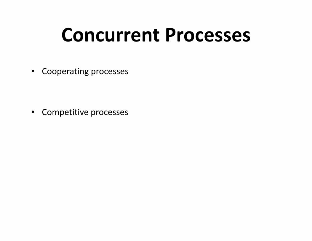
Drifting of Computer Clocks
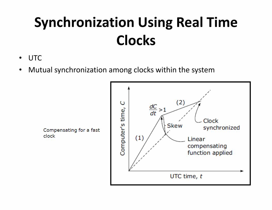
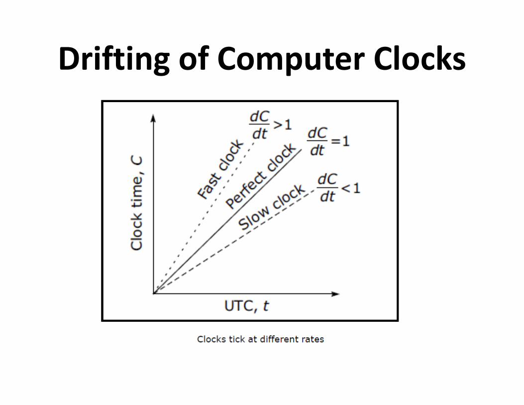
Synchronization Using Real Time
Clocks • UTC
• Mutual synchronization among clocks within the system

Issues in Clock Synchronization
• Ability for each node to read the other node’s clock value
• Time must never run backwards
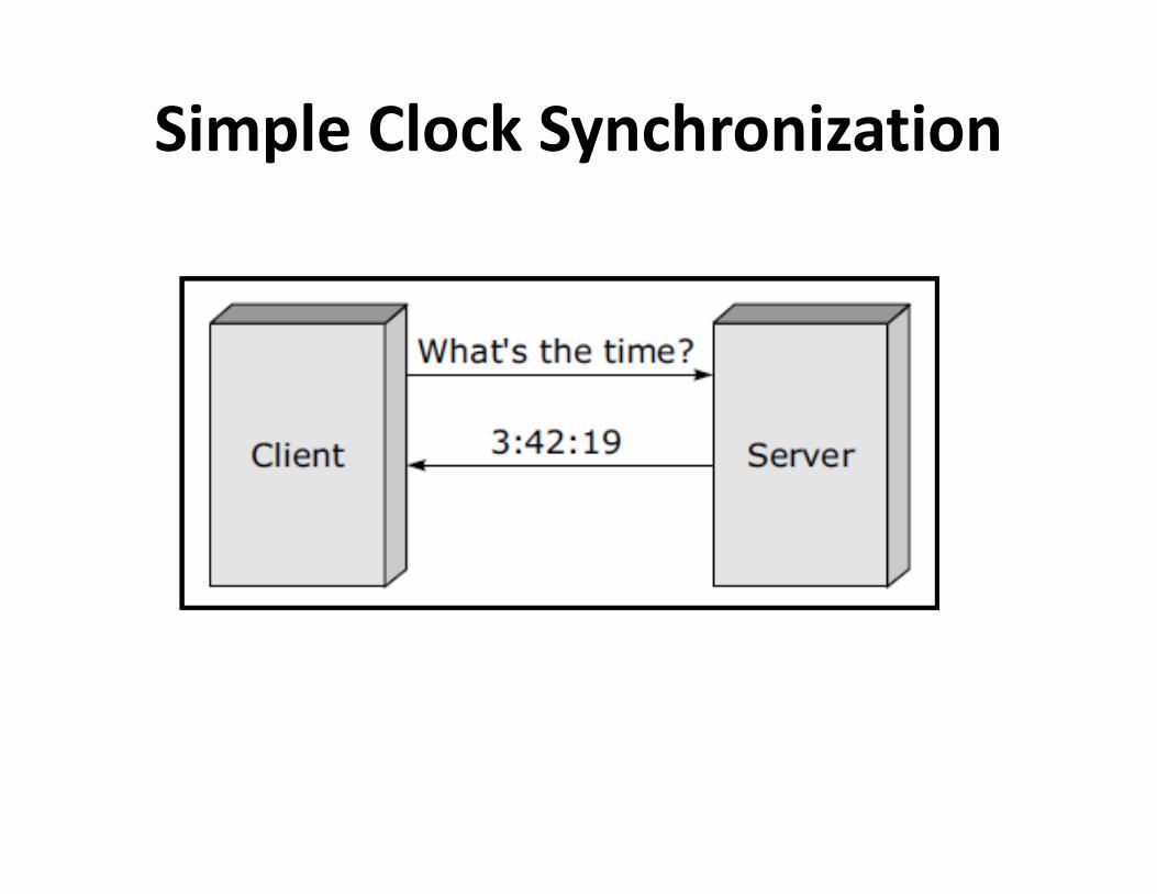
Simple Clock Synchronization
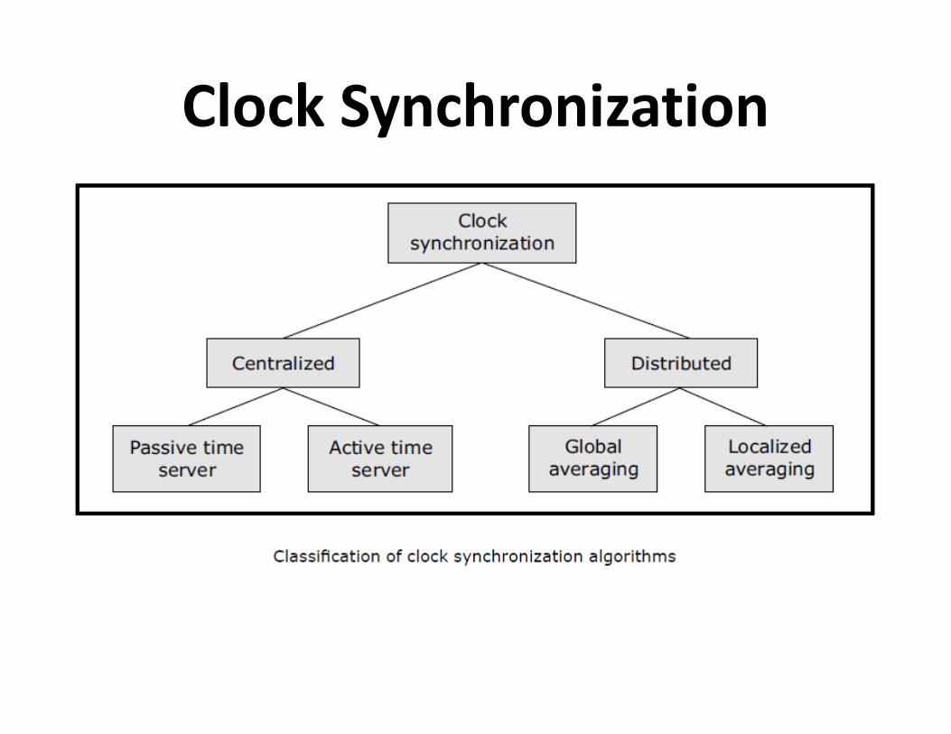
Clock Synchronization

Centralized Algorithms-1• Passive time server
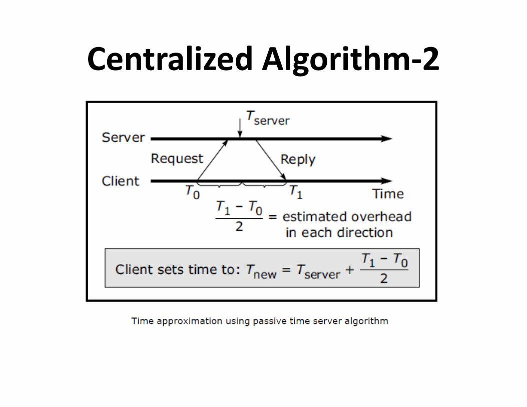
Centralized Algorithm-2
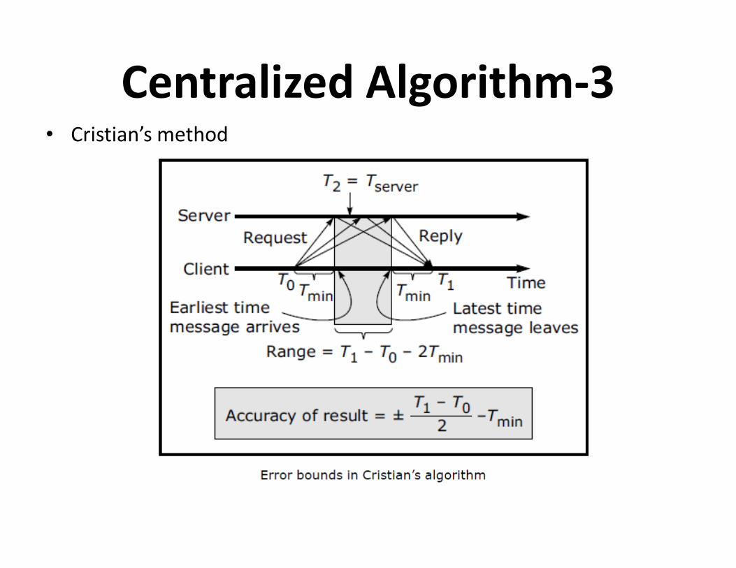
Centralized Algorithm-3• Cristian’s method
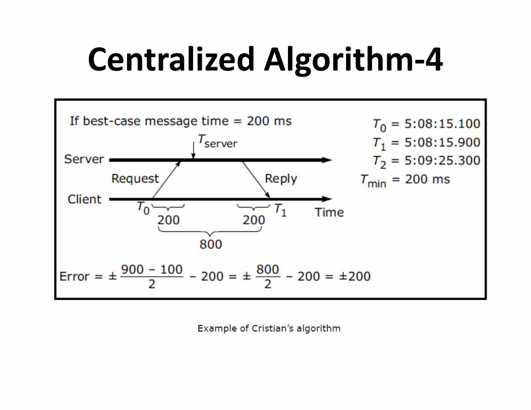
Centralized Algorithm-4
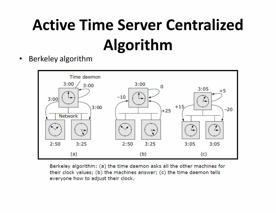
Active Time Server Centralized
Algorithm • Berkeley algorithm
Distributed Algorithms
• Characteristics
– Relevant information is distributed across machines
– Processes make decisions based only on local information
– Single points of failure must be avoided
– No common or global clock is available – No common or global clock is available
• Global averaging distributed algorithm
• Localized averaging distributed algorithm
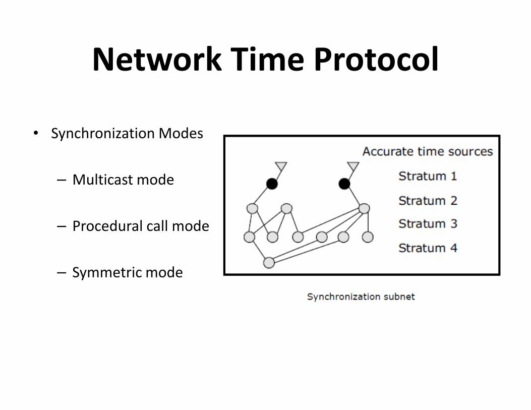
Network Time Protocol
• Synchronization Modes
– Multicast mode
– Procedural call mode
– Symmetric mode

Simple Network Time Protocol-1

Simple Network Time Protocol-2
Use of Synchronized Clocks
• At-most-once message delivery semantics
• Clock-based file system cache consistency
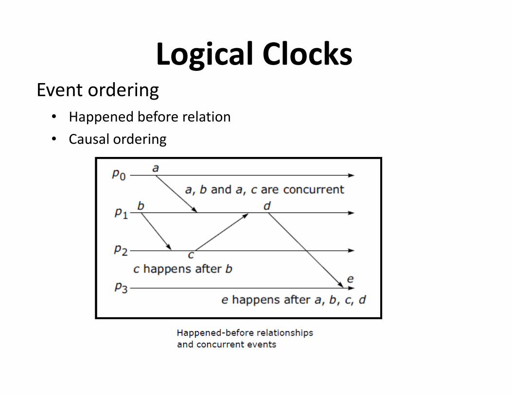
Event ordering
• Happened before relation
• Causal ordering
Logical Clocks
Lamport’s Idea of Logical Clocks
• Processes that don't interact don't matter (need a common
clock)
• Event ordering is key, rather than true time
• Absolute correctness is less important than consistency
(logical versus physical clocks)
Implementation of Logical Clocks
Conditions for correct functioning:
• C1: If a and b are two events in the same process, and a→ b, then we demand that C(a) < C(b).
• C2: If a corresponds to sending a message m, and b corresponds to receiving that message, then also C(a) < C(b).
• C3: A clock C associated with the process P must always go forward, never backwards. Hence corrections to a logical clock must be always made by adding a positive value , never subtracting from it.

Lamport’s Implementation Rules
• IR1:
– Each process P increments C by any two successive events.
This IR ensures that condition C1 is satisfied.
• IR2: • IR2:
– If event a is sending of a message m by process P, the
message m contains a timestamp Tm- C(a) and upon
receiving the message m by another process P, it sets its
clock C to a value greater or equal to its present value but
greater than Tm. This IR ensures that condition C2 is met.

Implementation Using Counters
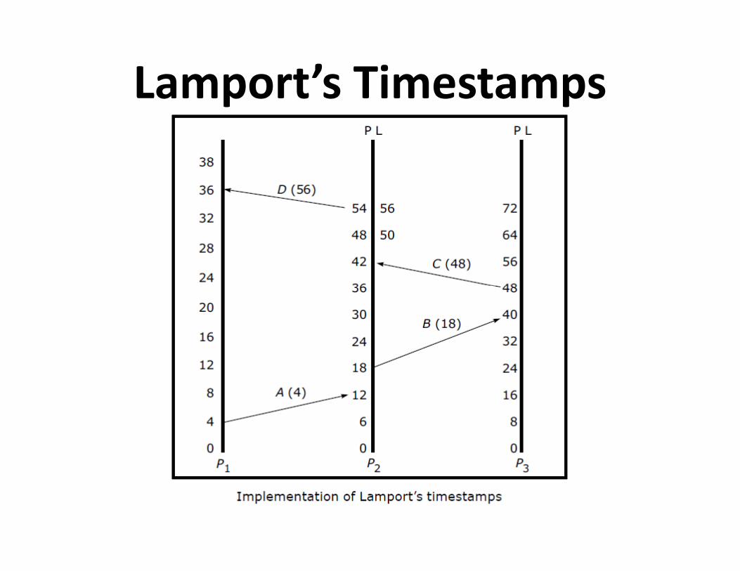
Lamport’s Timestamps

Position of Logical Clocks in
Middleware
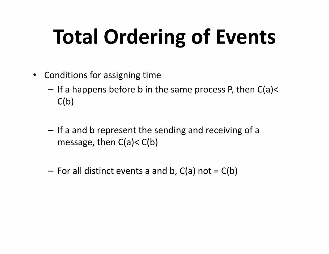
Total Ordering of Events
• Conditions for assigning time
– If a happens before b in the same process P, then C(a)<
C(b)
– If a and b represent the sending and receiving of a – If a and b represent the sending and receiving of a
message, then C(a)< C(b)
– For all distinct events a and b, C(a) not = C(b)

Totally Ordered Multicasting
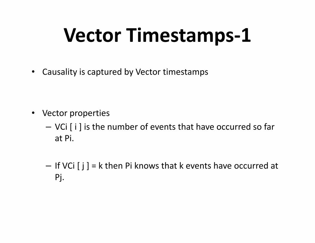
Vector Timestamps-1
• Causality is captured by Vector timestamps
• Vector properties
– VCi [ i ] is the number of events that have occurred so far – VCi [ i ] is the number of events that have occurred so far
at Pi.
– If VCi [ j ] = k then Pi knows that k events have occurred at
Pj.

Vector Timestamps-2

Global StateRecording global state
• By Chandy and Lamport
• Recording global state ( current state )
• Termination detection
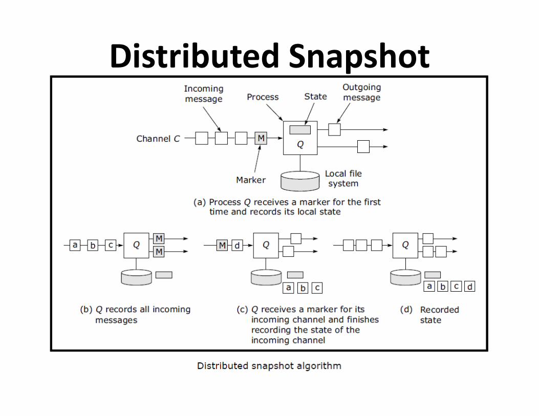
Distributed Snapshot

Mutual exclusion algorithms
– Centralized Algorithm
– Distributed Algorithm
Mutual Exclusion
– Distributed Algorithm
– Token Ring Algorithm

Centralized Mutual Exclusion
Algorithm • Messages used
– Request-R
– Grant-G
– Release-R
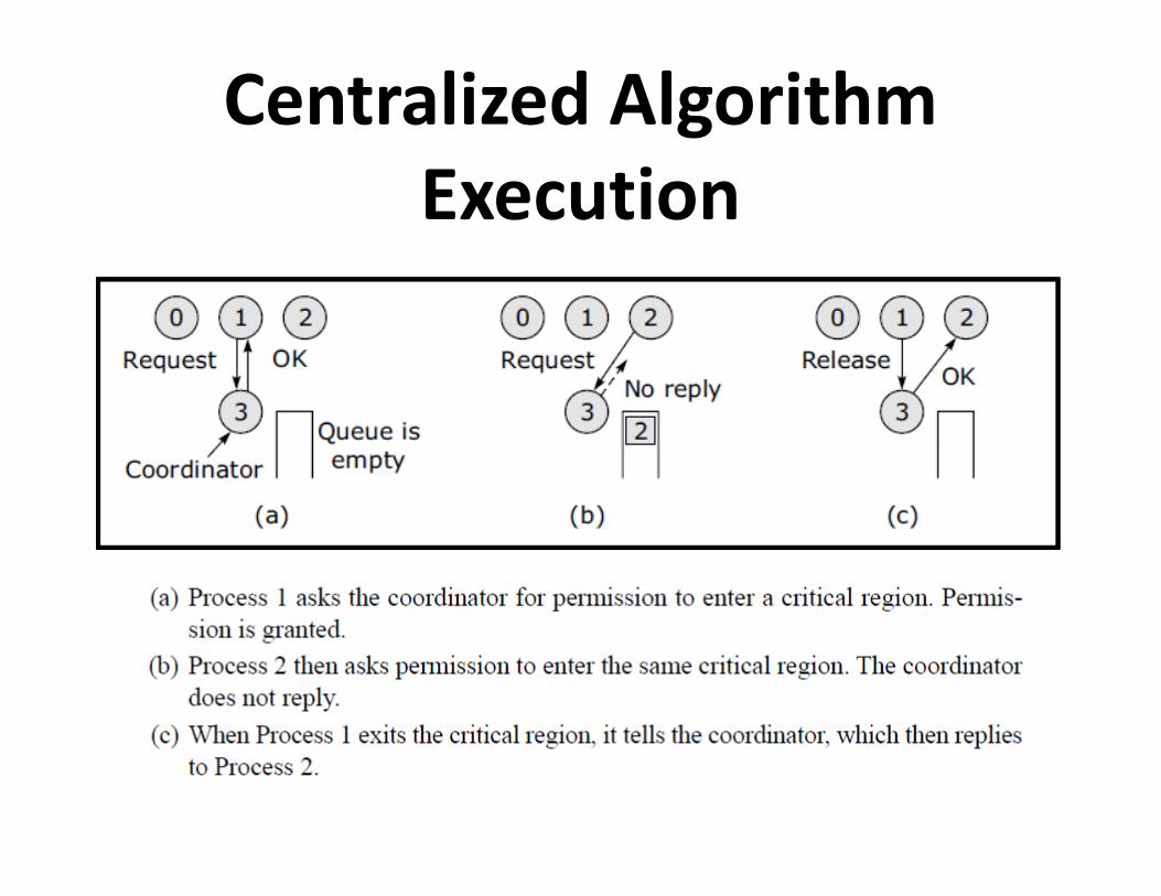
Centralized Algorithm
Execution

Distributed Algorithm
Execution

Token Ring Algorithm Execution

Comparison
Election Algorithms • Goals
– Attempt to locate the process with the highest process number and designate it as the coordinator and tell all the active processes about this coordinator
– To allow a recovered leader to re-establish control (or at – To allow a recovered leader to re-establish control (or at least, to identify the current leader)
• Algorithms
– Bully algorithm
– Ring algorithm
The Bully Algorithm
• Messages
– Election (E)—announce an election
– Reply (R) — acknowledge election msg– Reply (R) — acknowledge election msg
– Coordinator ( C) — announce new coordinator

Bully Algorithm - Example
0
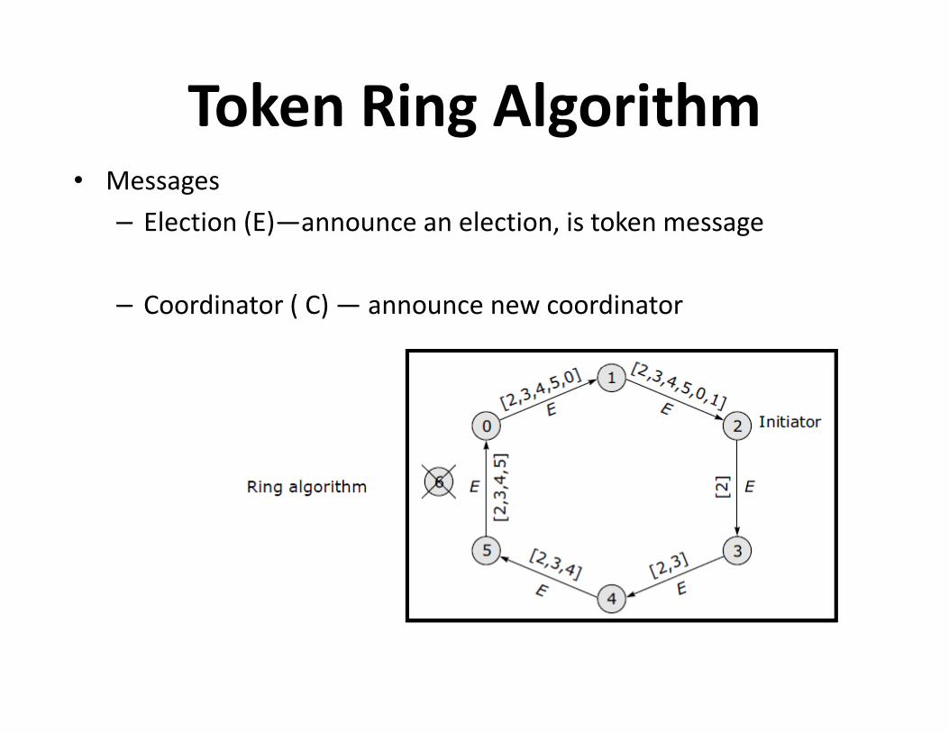
Token Ring Algorithm• Messages
– Election (E)—announce an election, is token message
– Coordinator ( C) — announce new coordinator
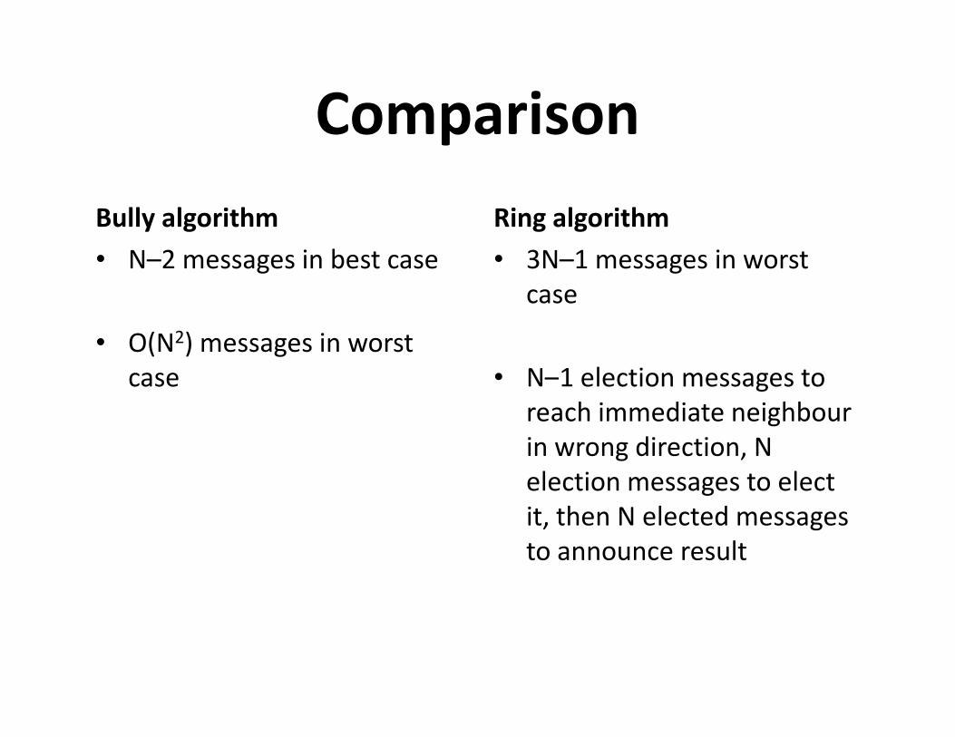
Comparison
Bully algorithm
• N–2 messages in best case
• O(N2) messages in worst
case
Ring algorithm
• 3N–1 messages in worst
case
• N–1 election messages to case • N–1 election messages to
reach immediate neighbour
in wrong direction, N
election messages to elect
it, then N elected messages
to announce result

Election in a Wireless Network

Basic concepts
• Resources
– Preemptable resources
Deadlocks in Distributed Systems
– Non-preemptable resources
• Sequence of events: request, allocate, and release
• Request →Allocate →Use →Release

Distributed Deadlocks
• Types
– Communication deadlocks
– Resource deadlocks
• Necessary and sufficient conditions for deadlock to occur• Necessary and sufficient conditions for deadlock to occur
– Mutual exclusion condition
– Hold and wait condition
– No preemption condition
– Circular wait condition

Concept of Cycle

Deadlock Modelling
Basic terminologies
– Directed graphs
– Path – Path
– Cycle
– Reachable set
– Knot
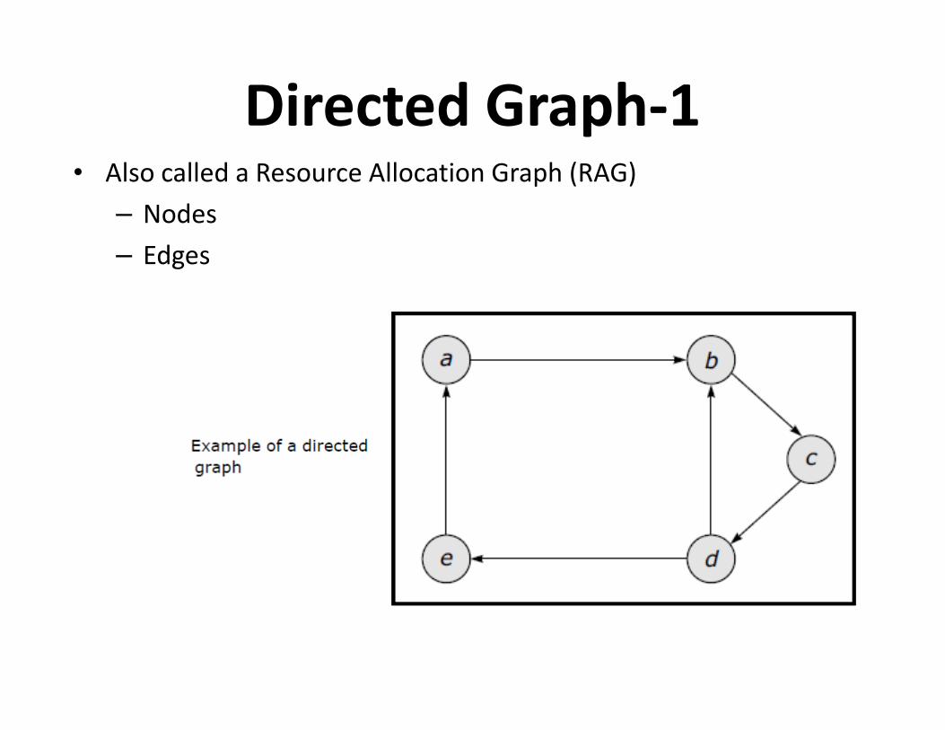
Directed Graph-1 • Also called a Resource Allocation Graph (RAG)
– Nodes
– Edges

Directed Graph-2

Elements of RAG
• Process node
• Resource node
• Assignment edge• Assignment edge
• Request edge
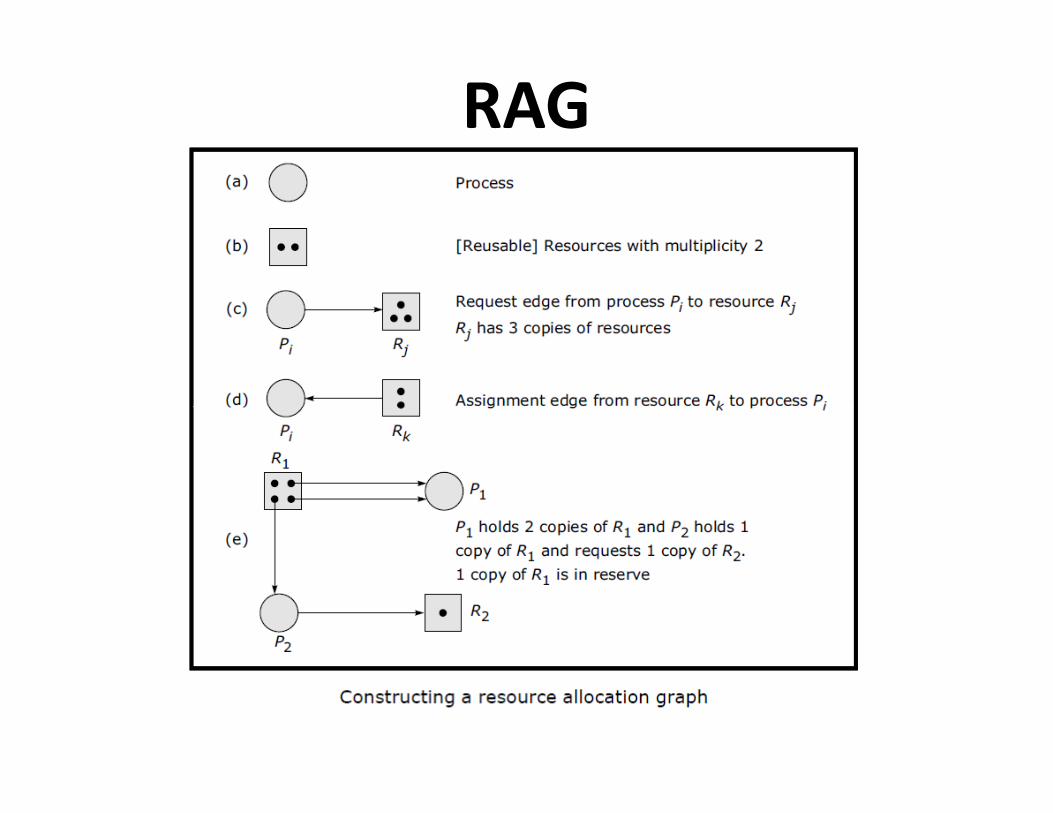
RAG

RAG Example
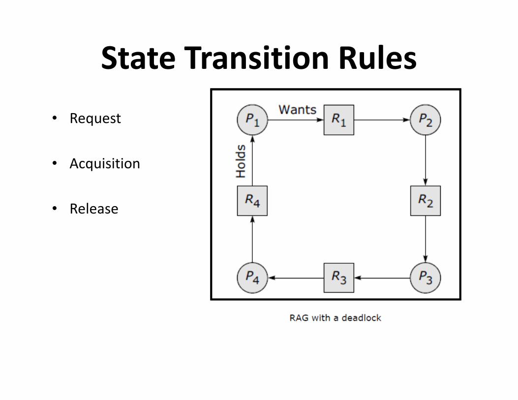
State Transition Rules
• Request
• Acquisition
• Release • Release
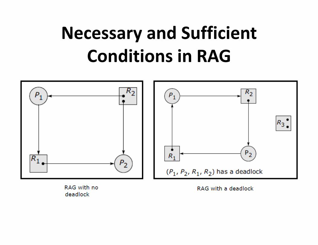
Necessary and Sufficient
Conditions in RAG
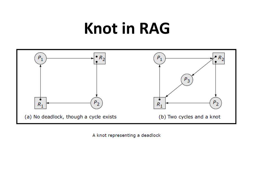
Knot in RAG

Wait For Graph : WFG-1

Wait For Graph : WFG-2
• If graph contains no cycles ⇒ no deadlock
• If graph contains a cycle ⇒
– if only one instance per resource type, then deadlock
– if several instances per resource type, possibility of
deadlock

Handling Deadlock in Distributed
Systems
• The ostrich algorithm (ignore the problem, most common
approach)
• Avoidance (avoid deadlocks by allocating resources carefully)• Avoidance (avoid deadlocks by allocating resources carefully)
• Prevention (make deadlocks structurally impossible)
• Detection (let deadlocks occur, detect them, and then try to
recover)

Notion of Safety • Deadlock
– No forward progress can be made.
• Unsafe state
– A state which does not have a safe sequence and that may allow
a deadlock to occur.
• Safe state • Safe state
– A state is safe if it is not in a deadlock state, and if a sequence of
processes exist such that there are enough resources for the
first process to finish, and as each process finishes and releases
its resources there are enough for the next process to finish.
• Safe sequence
– For a particular safe state, there can be many process orderings.
Any ordering of the processes which can guarantee the
completion of all processes is called a safe sequence.
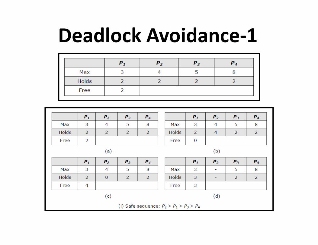
Deadlock Avoidance-1
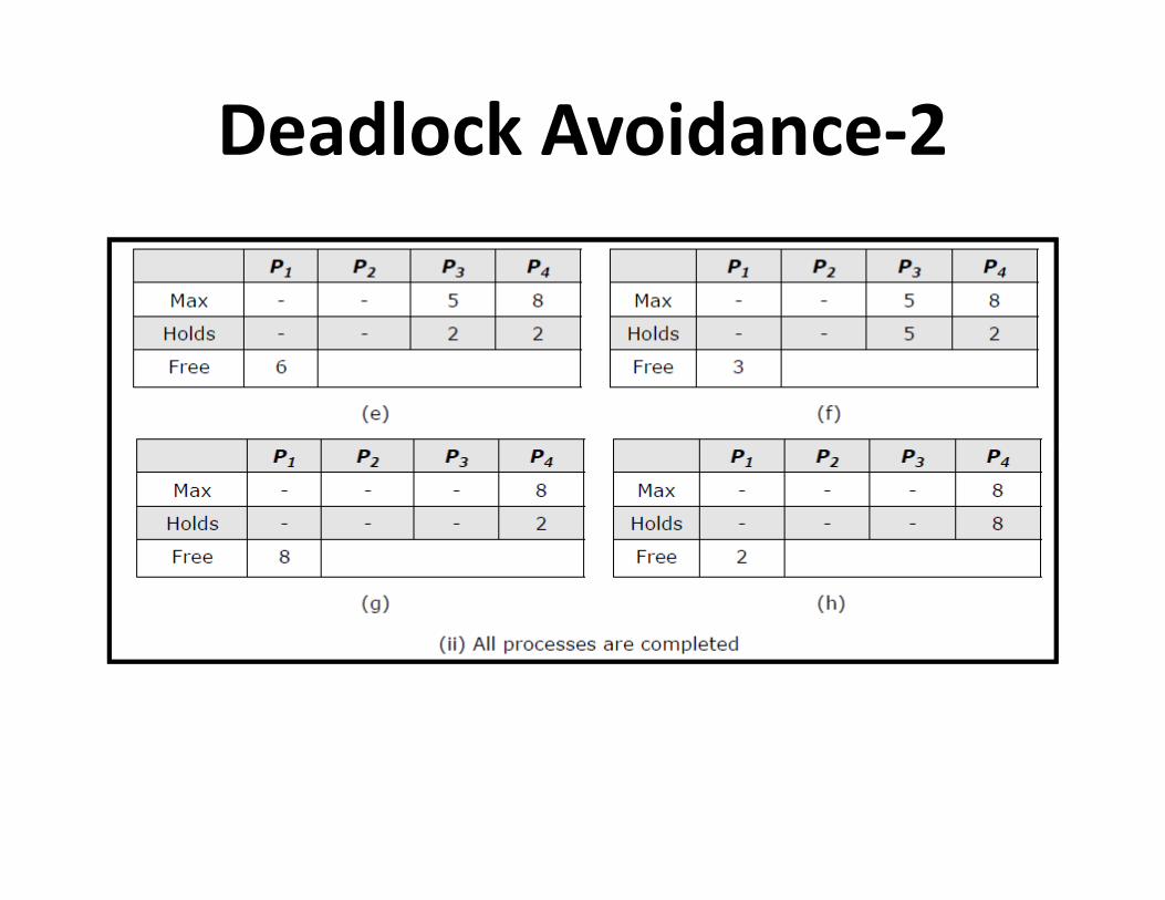
Deadlock Avoidance-2

Another Example of Resource
Allocation
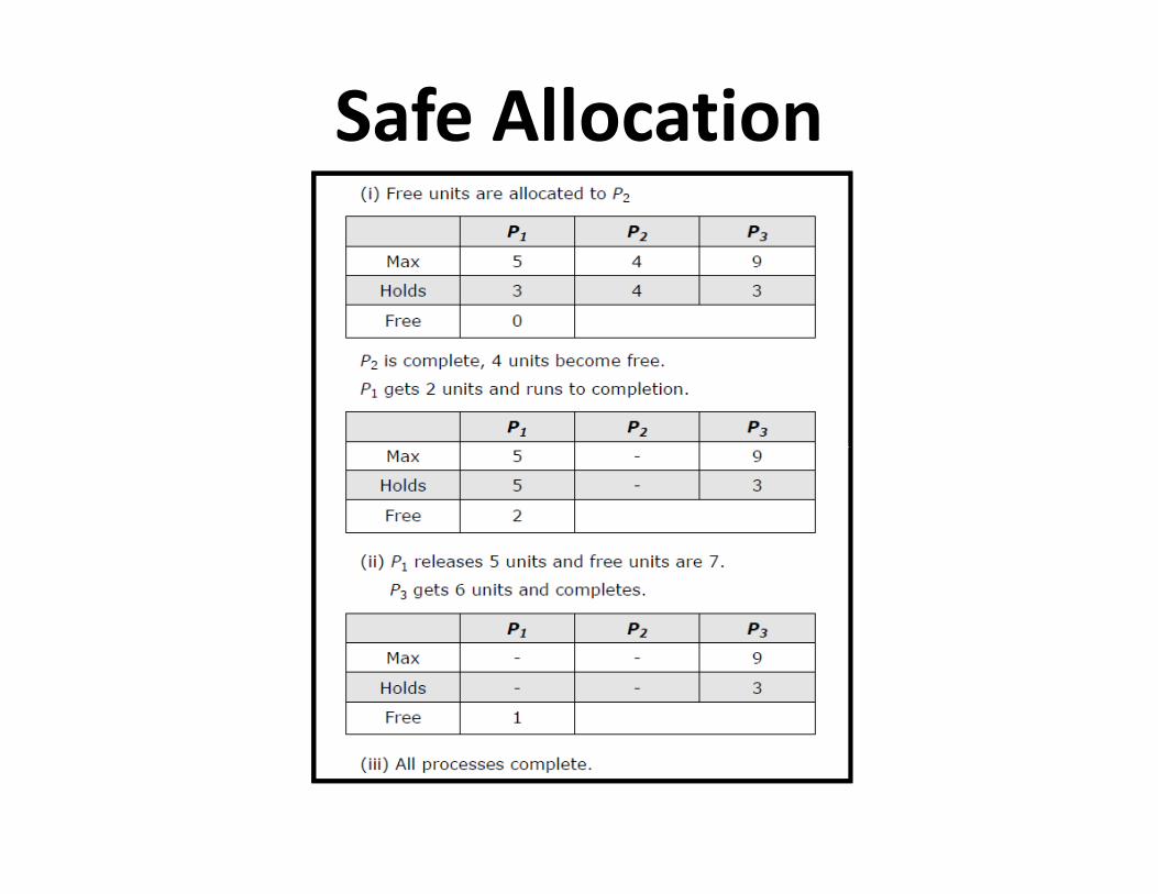
Safe Allocation

Unsafe Allocation

Distributed Deadlock Prevention
• Collective requests (denies the hold and wait condition)
• Ordered requests (denies the circular wait condition)• Ordered requests (denies the circular wait condition)
• Preemption (denies the no preemption condition)
Schemes for Killing Transactions
• Wait-die
• Wound-wait

Wait-die – If an old process
wants a resource
held by a young
process, the old one
will wait.
– If a young process
wants a resource
held by an old
process, the young
process will be
killed.
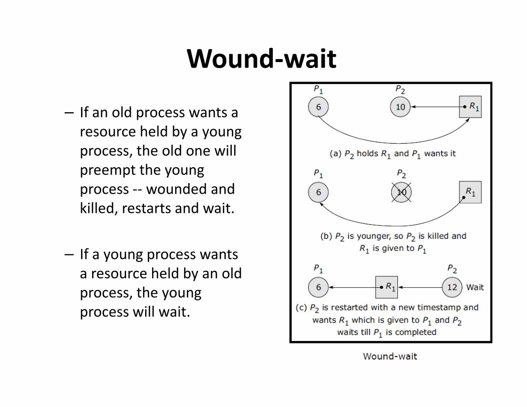
Wound-wait
– If an old process wants a
resource held by a young
process, the old one will
preempt the young
process -- wounded and
killed, restarts and wait.killed, restarts and wait.
– If a young process wants
a resource held by an old
process, the young
process will wait.

Distributed Deadlock Detection-1
• Features
• Correctness in terms of progress and safety
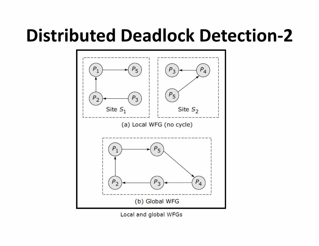
Distributed Deadlock Detection-2
Deadlock Detection Techniques
• Centralized control
• Hierarchical control
• Distributed control • Distributed control

Centralized Control
• Local deadlock
• Global WFG
• Message transfer • Message transfer
– Continuous transfer
– Periodic transfer
– Transfer on request
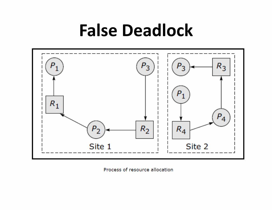
False Deadlock
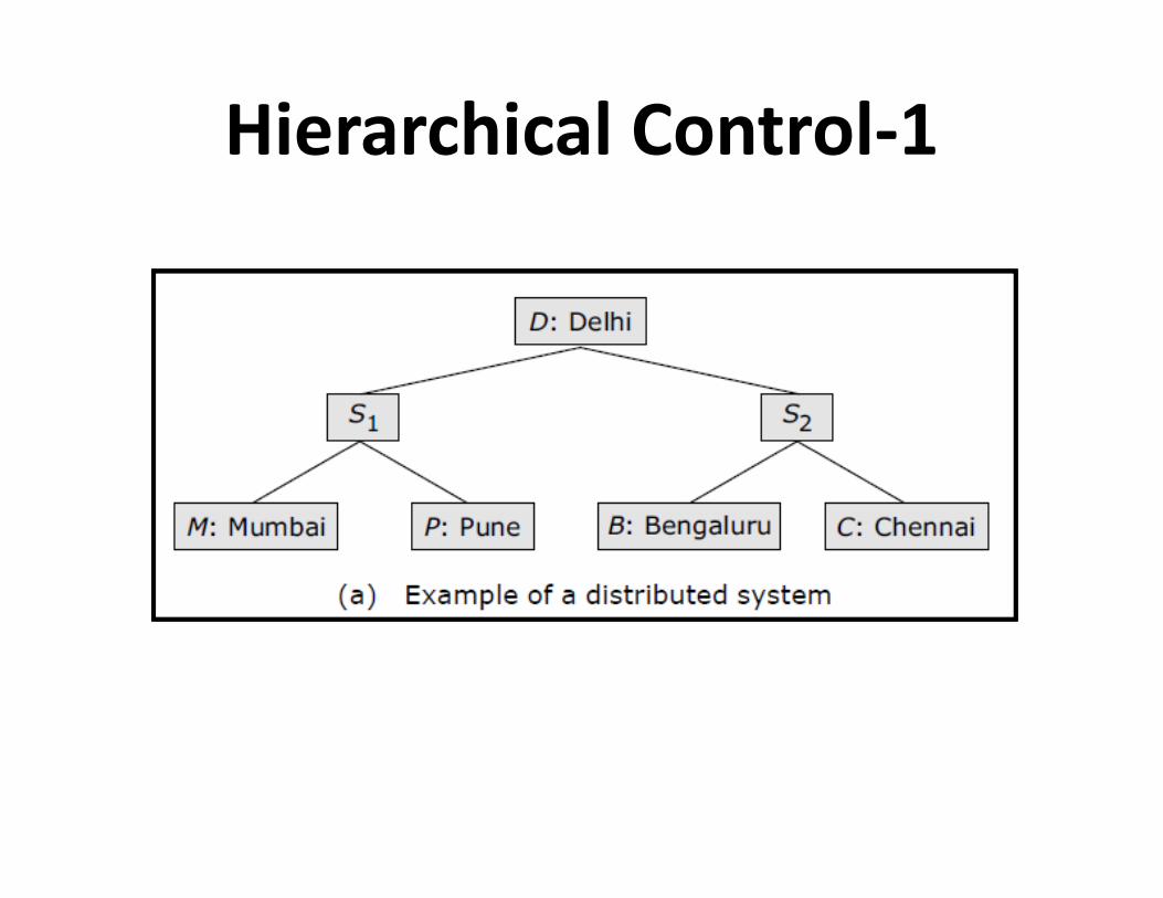
Hierarchical Control-1

Hierarchical Control-2
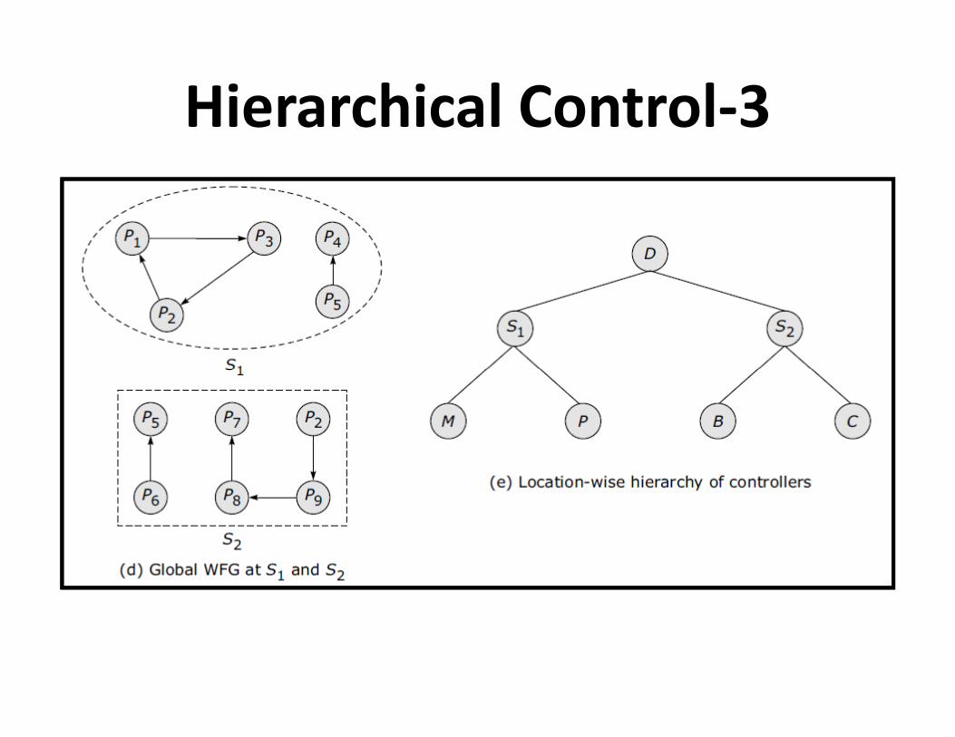
Hierarchical Control-3
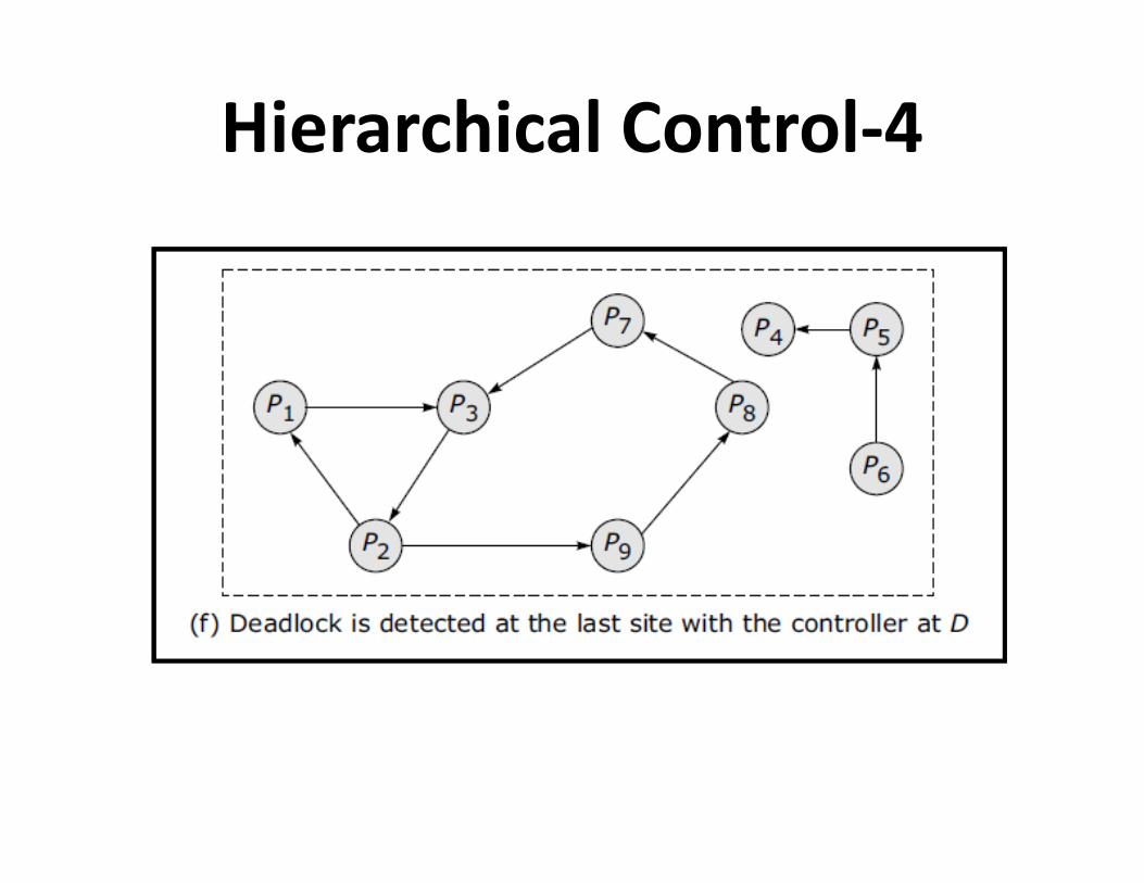
Hierarchical Control-4
Distributed Deadlock Detection
• WFG based distributed approach
• Probe based distributed algorithm• Probe based distributed algorithm

WFG-based Distributed Approach

Probe-based Distributed
Algorithm• The Chandy-Misra-Haas algorithm
Distributed Deadlock Recovery
• Recovery through preemption
• Recovery through rollback
• Recovery through killing processes
Issues in Recovery from Deadlock
• Selection of victims
• Minimization of recovery costs• Minimization of recovery costs
• Prevention of starvation
• Use of transaction mechanism