47 ATEX SERIES · INTERPUMPGROUP Modello Model Modèle Modell Modelo Modelo Portata Flow rate...
36
INTERPUMPGROUP Modello Model Modèle Modell Modelo Modelo Portata Flow rate Débit Förderstrom Caudal Fluxo Pressione Pressure Pression Druck Presión Pressão g/m rpm t/m upm r/m r/m Potenza Power Puissance Leistung Potencia Poder Peso Weight Poids Gewicht Peso Peso Inlet l/min gpm bar MPa psi Hp kW Kg Ibs °C Lt. WS133 STD. 13 3.43 120 12 1750 1450 4.0 2.94 14.0 30.8 40 1.1 WS171 STD. 13 3.43 170 17 2465 1450 5.5 4.04 14.5 31.9 40 1.1 WS101 STD. 15 3.96 100 10 1450 1450 4.0 2.94 14.0 30.8 40 1.1 WS131 STD. 15 3.96 130 13 1885 1450 5.5 4.04 14.5 31.9 40 1.1 WS151 STD. 15 3.96 150 15 2175 1450 5.5 4.04 14.5 31.9 40 1.1 WS201 STD. 15 3.96 200 20 2900 1450 7.5 5.51 14.5 31.9 40 1.1 WS251 STD. 15 3.96 250 25 3600 1450 10.0 7.35 14.5 31.9 40 1.1 WS92 STD. 18 4.75 90 9 1300 1450 4.0 2.94 14.0 30.8 40 1.1 WS162 STD. 18 4.75 160 16 2320 1450 7.5 5.51 14.5 31.9 40 1.1 WS132 STD. 18.7 4.94 120 12 1750 1450 5.5 4.04 14.5 31.9 40 1.1 WS82 STD. 21 5.55 80 8 1160 1450 4.0 2.94 14.0 30.8 40 1.1 WS102 STD. 21 5.55 100 10 1450 1450 5.5 4.04 14.5 31.9 40 1.1 WS152 STD. 21 5.55 150 15 2175 1450 7.5 5.51 14.5 31.9 40 1.1 WS202 STD. 21 5.55 200 20 2900 1450 10.0 7.35 14.5 31.9 40 1.1 WS252 STD. 21 5.55 250 25 3600 1450 14.0 10.29 14.5 31.9 40 1.1 WS1625 STD. 25 6.60 160 16 2320 1450 10.5 7.72 15.0 33.0 40 1.1 WS1630 STD. 30 7.92 160 16 2320 1450 12.5 9.50 15.0 33.0 40 1.1 I GB F LIBRETTO DATI TECNICI TECHNICAL SPECIFICATIONS BOOKLET MANUEL DES CARACTÉRISTIQUES TECHNIQUES D E P TECHNISCHES DATENBLATT FOLLETO DE DATOS TÉCNICOS FOLHETO DOS DADOS TÉCNICOS Questo libretto deve essere letto e compreso in accordo al manuale generico “Istruzioni d’uso e manutenzione” e al manuale “Protezione antideflagrante ATEX”. This booklet must be read and understood according to the generic “Use and Maintenance” manual and the “ATEX explosion protection” manual. Lire et s'assurer d'avoir compris ce manuel, ainsi que celui des “Instructions pour l'utilisation et l'entretien” et le manuel “Protection antidéflagrante - Réglementation ATEX”. Dieses Datenblatt muss lt. der allgemeinen “Betriebs- und Wartungsanleitung” und der Anleitung “ATEX-Explosionsschutz" gelesen und verstanden werden. Este folleto se ha de leer y entender de acuerdo con el manual general de “Instrucciones de uso y mantenimiento” y el manual de “Protección antideflagrante ATEX”. Este folheto deve ser lido e compreendido de acordo com o manual geral “Instruções de uso e manutenção” e o manual “Proteção contra explosão ATEX”. 47 ATEX SERIES II 2G Ex h IIC T4 Gb II 2D Ex h IIIC T135°C Db
Transcript of 47 ATEX SERIES · INTERPUMPGROUP Modello Model Modèle Modell Modelo Modelo Portata Flow rate...

INTERPUMPGROUP
ModelloModel
ModèleModellModeloModelo
PortataFlow rate
Débit Förderstrom
CaudalFluxo
PressionePressurePression
DruckPresiónPressão
g/mrpmt/mupmr/mr/m
PotenzaPower
PuissanceLeistungPotencia
Poder
PesoWeightPoids
GewichtPesoPeso
Inlet
l/min gpm bar MPa psi Hp kW Kg Ibs °C Lt.
WS133 STD. 13 3.43 120 12 1750 1450 4.0 2.94 14.0 30.8 40 1.1
WS171 STD. 13 3.43 170 17 2465 1450 5.5 4.04 14.5 31.9 40 1.1
WS101 STD. 15 3.96 100 10 1450 1450 4.0 2.94 14.0 30.8 40 1.1
WS131 STD. 15 3.96 130 13 1885 1450 5.5 4.04 14.5 31.9 40 1.1
WS151 STD. 15 3.96 150 15 2175 1450 5.5 4.04 14.5 31.9 40 1.1
WS201 STD. 15 3.96 200 20 2900 1450 7.5 5.51 14.5 31.9 40 1.1
WS251 STD. 15 3.96 250 25 3600 1450 10.0 7.35 14.5 31.9 40 1.1
WS92 STD. 18 4.75 90 9 1300 1450 4.0 2.94 14.0 30.8 40 1.1
WS162 STD. 18 4.75 160 16 2320 1450 7.5 5.51 14.5 31.9 40 1.1
WS132 STD. 18.7 4.94 120 12 1750 1450 5.5 4.04 14.5 31.9 40 1.1
WS82 STD. 21 5.55 80 8 1160 1450 4.0 2.94 14.0 30.8 40 1.1
WS102 STD. 21 5.55 100 10 1450 1450 5.5 4.04 14.5 31.9 40 1.1
WS152 STD. 21 5.55 150 15 2175 1450 7.5 5.51 14.5 31.9 40 1.1
WS202 STD. 21 5.55 200 20 2900 1450 10.0 7.35 14.5 31.9 40 1.1
WS252 STD. 21 5.55 250 25 3600 1450 14.0 10.29 14.5 31.9 40 1.1
WS1625 STD. 25 6.60 160 16 2320 1450 10.5 7.72 15.0 33.0 40 1.1
WS1630 STD. 30 7.92 160 16 2320 1450 12.5 9.50 15.0 33.0 40 1.1
IGBF
LIBRETTO DATI TECNICITECHNICAL SPECIFICATIONS BOOKLET
MANUEL DES CARACTÉRISTIQUES TECHNIQUES
DEP
TECHNISCHES DATENBLATTFOLLETO DE DATOS TÉCNICOS
FOLHETO DOS DADOS TÉCNICOS
Questo libretto deve essere letto e compreso in accordo al manuale generico “Istruzioni d’uso e manutenzione” e al manuale “Protezione antideflagrante ATEX”.
This booklet must be read and understood according to the generic “Use and Maintenance” manual and the “ATEX explosionprotection” manual.
Lire et s'assurer d'avoir compris ce manuel, ainsi que celui des “Instructions pour l'utilisation et l'entretien” et le manuel“Protection antidéflagrante - Réglementation ATEX”.
Dieses Datenblatt muss lt. der allgemeinen “Betriebs- und Wartungsanleitung” und der Anleitung “ATEX-Explosionsschutz" gelesenund verstanden werden.
Este folleto se ha de leer y entender de acuerdo con el manual general de “Instrucciones de uso y mantenimiento” y el manual de “Protección antideflagrante ATEX”.
Este folheto deve ser lido e compreendido de acordo com o manual geral “Instruções de uso e manutenção” e o manual “Proteçãocontra explosão ATEX”.
47 ATEX SERIESII 2G Ex h IIC T4 Gb
II 2D Ex h IIIC T135°C Db

ModelloModel
ModèleModellModeloModelo
PortataFlow rate
Débit Förderstrom
CaudalFluxo
PressionePressurePression
DruckPresiónPressão
g/mrpmt/mupmr/mr/m
PotenzaPower
PuissanceLeistungPotencia
Poder
PesoWeightPoids
GewichtPesoPeso
Inlet
L/min gpm bar MPa psi Hp kW Kg Ibs °C Lt.
W913 STD. 15 3.96 130 13 1885 1750 5.5 4.04 14.0 30.8 40 1.1
W921 STD. 15 3.96 200 20 2900 1750 7.5 5.51 14.5 31.9 40 1.1
W928T9281
STD. 15 3.96 275 27.5 4000 1750 11.0 8.08 14.5 31.9 40 1.1
W912 STD. 18 4.75 100 10 1450 1750 5.0 3.67 14.0 30.8 40 1.1
W916 STD. 18 4.75 160 16 2320 1750 7.5 5.51 14.5 31.9 40 1.1
W914 STD. 21 5.55 100 10 1450 1750 5.5 4.04 14.5 31.9 40 1.1
W922 STD. 21 5.55 200 20 2900 1750 10.0 7.35 14.5 31.9 40 1.1
TS1630 STD. 30 7.92 160 16 2320 1750 12.5 9.20 15.0 33.0 40 1.1
TS1636 STD. 36 9.51 160 16 2320 1750 15.011.0
215.0 33.0 40 1.1
HT4715 HT 15 3.96 160 16 2320 1450 6.2 4.56 14.5 31.9 85 1.1
VHT4715 VHT 15 3.96 160 16 2320 1450 6.2 4.56 14.5 31.9 110 1.1
HT4718 HT 18 4.75 160 16 2320 1450 7.5 5.51 14.5 31.9 85 1.1
VHT4718 VHT 18 4.75 160 16 2320 1450 7.5 5.51 14.5 31.9 110 1.1
HT4721 HT 21 5.55 140 14 2030 1450 7,5 5.51 14.5 31.9 85 1.1
VHT4721 VHT 21 5.55 140 14 2030 1450 7.5 5.51 14.5 31.9 110 1.1
HT4723 HT 23 6.07 160 16 2320 1450 10.0 7.35 14.5 31.9 85 1.1
VHT4723 VHT 23 6.07 160 16 2320 1450 10.0 7.35 14.5 31.9 110 1.1
SSE2013 SS 13 3.43 200 20 2900 1450 6.8 5.00 12.8 28.2 85 1.1
SSE2015 SS 15 3.96 200 20 2900 1450 7.8 5.73 12.8 28.2 85 1.1
SSE1518 SS 18 4.75 150 15 2175 1450 7.0 5.14 12.8 28.2 85 1.1
SSE2021 SS 21 5.55 200 20 2900 1450 10.9 8.01 12.8 28.2 85 1.1
SSU2015 SS 15 3.96 200 20 2900 1750 7.8 5.73 12.8 28.2 85 1.1
SSU2018 SS 18 4.75 200 20 2900 1750 9.4 6.91 12.8 28.2 85 1.1
SSU1521 SS 21 5.55 150 15 2175 1750 7.5 5.51 12.8 28.2 85 1.1
1

2

DIS
. C
OD
. 47
.95
26
.00
SE
RIE
47
3

212019181716151413121110987654321
POS
47.0
215.
3547
.021
9.35
47.0
206.
3547
.021
0.35
47.0
218.
3547
.023
0.35
47.0
204.
3547
.021
7.35
90.3
922.
00
98.2
107.
00
47.0
100.
22
90.9
126.
00
90.1
625.
00
91.8
378.
00
90.3
913.
00
47.1
513.
22
99.3
039.
00
36.7
032.
01
98.2
220.
0098
.222
2.00
90.3
847.
00
36.2
002.
51
94.7
376.
00
36.2
001.
76
36.2
003.
66
90.3
841.
00
96.7
020.
00
99.3
206.
00
47.1
201.
4147
.120
2.41
COD
.
Alb.
ecc
. C.
10 -
WS1
71Al
b. e
cc. C.
10 -
WS1
33 W
913
W92
1Al
b. e
cc. C.
12 -
WS1
51 W
S201
W91
6Al
b. e
cc. C.
12 -
WS1
31Al
b. e
cc. C.
12 -
WS1
01 W
912
Alb.
ecc
. C.
13 -
W91
4 W
922
Alb.
ecc
. C.
16 -
WS1
02Al
b. e
cc. C.
16 -
WS8
2 W
S152
WS2
02
OR D
.133
.02x
2.62
NBR
70S
H 3
525
Tapp
o co
n as
ta G
3/8
”x64
Cart
er p
ompa
Bocc
ola
D.
22.0
x25.
0x30
.0
Anel
lo r
ad. D
. 22
.0x3
2.0x
2.5
2
Cusc
inet
to a
rul
li
OR D
. 67
.95x
2.62
NBR
70S
H 3
268
Cope
rchi
o la
tera
le la
to s
pia
Vite
M8x
16 U
NI
5931
Gr.
Val
vola
d’a
spira
z. /
man
data
1
Tapp
o M
24x2
x16.
5 -
BRAS
S
4
Tapp
o M
24x2
x16.
5 -
NIC
KEL
5
OR D
. 20
.29x
2.62
NBR
90S
H 3
081
4 5
Gui
da v
alvo
la
1
Mol
la D
m. 9.
4x14
.8
1
Valv
ola
sfer
ica
1
Sede
val
vola
1
OR D
. 17
.13x
2.62
NBR
70S
H 3
068
1
Ros
etta
D.
8.4x
15.0
x1.5
Vite
M8x
70 U
NI
5737
Test
ata
D.
pom
pa 2
0-22
-BR
ASS
Test
ata
D.
pom
pa 2
0-22
-N
ICKE
L
DES
CRIZ
ION
E –
DES
CRIP
TIO
N -
KIT
111133221866666666881NR
46454443424140393837363534
333231302928272625242322POS
47.2
169.
70
47.1
000.
51
90.2
705.
00
47.0
805.
70
90.3
616.
00
90.1
648.
00
97.5
678.
0097
.568
0.00
47.1
510.
22
47.2
195.
66
96.7
280.
00
90.5
067.
00
47.0
404.
09
96.7
286.
00
90.0
755.
00
99.3
099.
00
90.3
585.
00
98.2
036.
00
98.2
266.
00
47.1
601.
22
99.1
912.
00
47.0
300.
01
47.0
504.
66
97.7
380.
00
91.4
892.
00
90.0
557.
00
COD
.
Anel
lo in
term
edio
D.
20
2
8 71
Anel
lo d
i tes
ta D
. 20
7 2
8
An.
ten.
alt.
D.
20x3
5x7.
5/4.
5 H
P28
69
Anel
lodi
fon
doD
. 20
x35
10 2
8
OR D
. 34
.65x
1.78
NBR
70S
H 2
137
10 2
8
Anel
lo r
ad. D
. 30
.0x5
5.0x
7.0
3
Spes
sore
0.1
mm
.Sp
esso
re 0
.3 m
m.
Cope
rchi
o la
tera
le la
to P
TO
Vite
fis
sagg
io p
isto
ne
6
Ros
etta
D.
14.0
x18.
5x0.
5
6
Anel
lo a
ntie
st. D
. 11
.0x1
4.0x
1.5
6
Pist
one
D.
20x5
0
Ros
etta
D.
14.0
x28.
0x0.
5
6
Anel
lo d
’arr
esto
J45
Vite
ser
ragg
io b
iella
OR D
. 10
.82x
1.78
NBR
70S
H 2
043
6
Tapp
o G
1/4
”x8
per
sond
a D
. 6
Tapp
o G
3/4
”x16
Cope
rchi
o po
ster
iore
Vite
M 6
x30
UN
I 59
31
Biel
la c
ompl
eta
Gui
da p
isto
ne
Spin
otto
D.
13x3
5
Ling
uett
a 8.
0x7.
0x35
.0
Anel
lo d
’arr
esto
A12
DES
CRIZ
ION
E –
DES
CRIP
TIO
N -
KIT
333331-133333164111533316NR
5956555453525150494847POS
98.2
887.
00
90.2
710.
00
96.7
380.
00
98.2
100.
00
96.7
514.
00
98.2
176.
00
90.3
877.
00
70.2
118.
01
99.1
809.
00
96.6
939.
50
90.2
704.
00
COD
.
Targ
hett
a in
d. m
essa
a t
erra
An.
ten.
alt.
D.
20.0
x35.
0x8.
7 LP
28 6
9
Ros
etta
D.
17.5
x23.
0x1.
5
Tapp
o G
3/8
”x13
Ros
etta
D.
21.5
x27.
0x1.
5
Tapp
o G
1/2
”x10
OR D
. 39
.34x
2.62
NBR
70S
H 3
156
Spia
live
llo o
lio
Vite
M 6
x10
UN
I 59
31
Ros
etta
D.
6.4x
11.0
x0.7
An.
RES
TOP
D.
20.0
x35.
0x5.
5.0/
2.0
28 6
9 71
DES
CRIZ
ION
E –
DES
CRIP
TIO
N -
KIT
13111111113NR
Nr.
Pcs
.
Po
sizi
on
i in
clu
seP
osi
tio
ns
incl
ud
ed
KIT
Nr.
KIT
RIC
AM
BI
-S
PA
RE
KIT
S
6
4 -
56
-7
8(1
1)
KIT
1
316
KIT
2
241
KIT
3
3
31
-3
43
6 -
37
38
KIT
6
6
9 -
10
KIT
4
OT
TO
NE
BR
AS
S
6
9 -
10
KIT
5
NIC
KE
L
645
KIT
7
PIS
TO
NE
-P
IST
ON
D. 2
0
3
42
-4
3
KIT
10
1
42
-4
34
4 -
45
46
-4
75
6
KIT
28
3
44
-4
75
6
KIT
69
3
46
-4
7
KIT
71
NIC
KE
L
OT
TO
NE
BR
AS
S
WS2
01 W
916
WS1
52 W
S202
W
921
W92
2
WS8
2 W
S101
WS1
33 W
912
W91
3 W
S102
WS1
31 W
S151
WS1
71 W
914
PIS
TO
NE
–P
ISTO
N D
. 20
WS
82
-W
S1
01
-W
S1
33
-W
91
2W
91
3 -
WS
10
2 -
WS
13
1 -
WS
15
1W
S1
71
-W
S2
01
-W
91
6 -
WS
15
2W
S2
02
-W
92
1 -
W9
14
-W
92
2
4

DIS
. C
OD
. 47
.95
26
.00
SE
RIE
47
5

25242322212019181716151413121110987654321
POS
47.0
504.
66
97.7
380.
00
91.4
892.
00
90.0
557.
00
47.0
206.
3547
.021
8.35
90.3
922.
00
98.2
107.
00
47.0
100.
22
90.9
126.
00
90.1
625.
00
91.8
378.
00
90.3
913.
00
47.1
513.
22
99.3
039.
00
36.7
032.
01
98.2
220.
0098
.222
2.00
90.3
847.
00
36.2
002.
51
94.7
376.
00
36.2
001.
76
36.2
003.
66
90.3
841.
00
96.7
020.
00
99.3
206.
00
47.1
201.
4147
.120
2.41
COD
.
Gui
da p
isto
ne
Spin
otto
D.
13x3
5
Ling
uett
a 8.
0x7.
0x35
.0
Anel
lo d
’arr
esto
A12
Alb.
ecc
. C.
12 -
WS1
32 W
S162
Alb.
ecc
. C.
12 -
WS9
2
OR D
.133
.02x
2.62
NBR
70S
H 3
525
Tapp
o co
n as
ta G
3/8
”x64
Cart
er p
ompa
Bocc
ola
D.
22.0
x25.
0x30
.0
Anel
lo r
ad. D
. 22
.0x3
2.0x
2.5
2
Cusc
inet
to a
rul
li
OR D
. 67
.95x
2.62
NBR
70S
H 3
268
Cope
rchi
o la
tera
le la
to s
pia
Vite
M8x
16 U
NI
5931
Gr.
Val
vola
d’a
spira
z. /
man
data
1
Tapp
o M
24x2
x16.
5 -
BRAS
S
4Ta
ppo
M24
x2x1
6.5
-N
ICKE
L
5
OR D
. 20
.29x
2.62
NBR
90S
H 3
081
4 5
Gui
da v
alvo
la
1
Mol
la D
m. 9.
4x14
.8
1
Valv
ola
sfer
ica
1
Sede
val
vola
1
OR D
. 17
.13x
2.62
NBR
70S
H 3
068
1
Ros
etta
D.
8.4x
15.0
x1.5
Vite
M8x
70 U
NI
5737
Test
ata
pom
pa D
. 20
-22
-BR
ASS
Test
ata
pom
pa D
. 20
-22
-N
ICKE
L
DES
CRIZ
ION
E –
DES
CRIP
TIO
N -
KIT
3316111133221866666666881NR
5150494847464544434241403938373635343332313029282726POS
90.3
877.
00
70.2
118.
01
99.1
809.
00
96.6
939.
50
90.2
730.
00
47.2
170.
70
46.1
000.
51
90.2
725.
00
47.0
806.
70
90.3
616.
00
90.1
648.
00
97.5
678.
0097
.568
0.00
47.1
510.
22
47.2
195.
66
96.7
280.
00
90.5
067.
00
47.0
405.
09
96.7
286.
00
90.0
755.
00
99.3
099.
00
90.3
585.
00
98.2
036.
00
98.2
266.
00
47.1
601.
22
99.1
912.
00
47.0
300.
01
COD
.
OR D
. 39
.34x
2.62
NBR
70S
H 3
156
Spia
live
llo o
lio
Vite
M 6
x10
UN
I 59
31
Ros
etta
D.
6.4x
11.0
x0.7
An.
RES
TOP
D.
22.0
x35.
0x5.
5/2.
029
148
149
Anel
lo in
term
edio
D.
22
29
149
Anel
lo d
i tes
ta D
. 22
11 2
9
An.
ten.
alt.
D.
22.0
x35.
0x7.
0/4.
5 H
P29
148
Anel
lodi
fon
doD
. 22
x35
14 2
9
OR D
. 34
.65x
1.78
NBR
70S
H 2
137
14
29
Anel
lo r
ad. D
. 30
.0x5
5.0x
7.0
3
Spes
sore
0.1
mm
.Sp
esso
re 0
.3 m
m.
Cope
rchi
o la
tera
le la
to P
TO
Vite
fis
sagg
io p
isto
ne
6
Ros
etta
D.
14.0
x18.
5x0.
5
6
Anel
lo a
ntie
st. D
. 11
.0x1
4.0x
1.5
6
Pist
one
D.
22x5
0
Ros
etta
D.
14.0
x28.
0x0.
5
6
Anel
lo d
’arr
esto
J45
Vite
ser
ragg
io b
iella
OR D
. 10
.82x
1.78
NBR
70S
H 2
043
6
Tapp
o G
1/4
”x8
per
sond
a D
. 6
Tapp
o G
3/4
”x16
Cope
rchi
o po
ster
iore
Vite
M6x
30 U
NI
5931
Biel
la c
ompl
eta
DES
CRIZ
ION
E –
DES
CRIP
TIO
N -
KIT
11113333331-13333316411153NR
595655545352POS
98.2
887.
00
90.2
728.
00
96.7
380.
00
98.2
100.
00
96.7
514.
00
98.2
176.
00
COD
.
Targ
hett
a in
d. m
essa
a t
erra
An.
ten.
alt.
D.
22.0
x35.
0x8.
8 LP
29 1
48
Ros
etta
D.
17.5
x23.
0x1.
5
Tapp
o G
3/8
”x13
Ros
etta
D.
21.5
x27.
0x1.
5
Tapp
o G
1/2
”x10
DES
CRIZ
ION
E –
DES
CRIP
TIO
N -
KIT
131111NR
Nr.
Pcs
.
Po
sizi
on
i in
clu
seP
osi
tio
ns
incl
ud
ed
KIT
Nr.
KIT
RIC
AM
BI
-S
PA
RE
KIT
S
6
4 -
56
-7
8(1
1)
KIT
1
316
KIT
2
241
KIT
3
3
31
-3
43
6 -
37
38
KIT
6
6
9 -
10
KIT
4
OT
TO
NE
BR
AS
S
6
9 -
10
KIT
5
NIC
KE
L
645
KIT
11
PIS
TO
NE
-P
IST
ON
D. 2
2
3
42
-4
3
KIT
14
1
42
-4
34
4 -
45
46
-4
75
6
KIT
29
3
44
-4
75
6
KIT
14
8
3
46
-4
7
KIT
14
9
NIC
KE
L
OT
TO
NE
BR
AS
S
WS1
62
WS9
2 W
S132
PIS
TO
NE
-P
IST
ON
D.
22
WS
92
-W
S1
32
-W
S1
62
6

DIS
. C
OD
. 47
.95
28
.00
SE
RIE
47
7

28272625242322212019181716151413121110987654321
POS
47.1
601.
22
99.1
912.
00
47.0
300.
01
47.0
506.
66
97.7
380.
00
91.4
892.
00
90.0
557.
00
47.0
217.
35
90.3
922.
00
98.2
107.
00
47.0
100.
22
90.9
126.
00
90.1
625.
00
91.8
378.
00
90.3
913.
00
47.1
513.
22
99.3
039.
00
36.7
032.
01
98.2
224.
00
90.3
847.
00
36.2
002.
51
94.7
376.
00
36.2
001.
76
36.2
003.
66
90.3
841.
00
96.7
020.
00
99.3
206.
00
47.1
214.
41
COD
.
Cope
rchi
o po
ster
iore
Vite
M6x
30 U
NI
5931
Biel
la c
ompl
eta
Gui
da p
isto
ne
Spin
otto
D.
13x3
5
Ling
uett
a 8.
0x7.
0x35
.0
Anel
lo d
’arr
esto
A12
Alb.
ecc
. C.
16
OR D
. 13
3.02
x2.6
2 N
BR S
H. 70
352
5
Tapp
o co
n as
ta G
3/8
”x64
Cart
er p
ompa
Bocc
ola
D.
22.0
x25.
0x30
.0
Anel
lo r
ad. D
. 22
.0x3
2.0x
2.5
2
Cusc
inet
to a
rul
li
OR D
. 67
.95x
2.62
NBR
70S
H 3
268
Cope
rchi
o la
tera
le la
to s
pia
Vite
M 8
x16
UN
I 59
31
Gr.
Val
vola
d’a
spira
z. /
man
data
1
Tapp
o M
24x
1.5x
17.5
-N
ICKE
L
10
6
OR D
. 20
.29x
2.62
NBR
90S
H 3
081
106
Gui
da v
alvo
la
1
Mol
la D
m. 9.
4x14
.8
1
Valv
ola
sfer
ica
1
Sede
val
vola
1
OR D
. 17
.13x
2.62
NBR
70S
H 3
068
1
Ros
etta
D.
8.4x
15.0
x1.5
Vite
M8x
70 U
NI
5737
Test
ata
pom
pa D
. 16
–N
ICKE
L
DES
CRIZ
ION
E –
DES
CRIP
TIO
N -
KIT
1533316111133221866666666881NR
5453525150494847464544434241403938373635343332313029POS
98.2
100.
00
96.7
514.
00
98.2
176.
00
90.3
877.
00
70.2
118.
01
99.1
809.
00
96.6
939.
50
90.2
643.
00
47.2
172.
70
47.1
003.
51
90.2
642.
00
47.0
808.
70
90.3
616.
00
90.1
648.
00
97.5
678.
0097
.568
0.00
47.1
510.
22
47.2
196.
66
90.3
577.
00
90.5
033.
00
47.0
408.
56
47.2
117.
47
90.0
755.
00
99.3
099.
00
90.3
585.
00
98.2
036.
00
98.2
266.
00
COD
.
Tapp
o G
3/8
”x13
Ros
etta
D.
21.5
x27.
0x1.
5
Tapp
o G
1/2
”x10
OR D
. 39
.34x
2.62
NBR
70S
H 3
156
Spia
live
llo o
lio
Vite
M 6
x10
UN
I 59
31
Ros
etta
D.
6.4x
11.0
x0.7
An.
RES
TOP
D.
16.0
x30.
0x7.
3/4.
0 109
112
Anel
lo in
term
edio
D.
16
110
112
Anel
lo d
i tes
ta D
. 16
1
08 1
12
An.
ten.
alt.
D.
16.0
x30.
0x7.
0/4.
0 H
P10
9 11
2
Anel
lodi
fon
doD
. 16
11
1 11
2
OR D
. 34
.65x
1.78
NBR
70S
H 2
137 11
1 11
2
Anel
lo r
ad. D
. 30
x55x
7
3
Spes
sore
0.1
mm
.Sp
esso
re 0
.3 m
m.
Cope
rchi
o la
tera
le la
to P
TO
Vite
fis
sagg
io p
isto
ne
107
OR D
. 7.
66x1
.78
NBR
70S
H 2
031
1
07
Anel
lo a
ntie
st. D
. 8x
11x1
.5
107
Pist
one
D.
16x4
9
Anel
lo d
i pro
tezi
one
Anel
lo d
’arr
esto
J45
Vite
ser
ragg
io b
iella
OR D
. 10
.82x
1.78
NBR
70S
H 2
043
Tapp
o G
1/4
”x8
per
sond
a D
. 6
Tapp
o G
3/4
”x16
DES
CRIZ
ION
E –
DES
CRIP
TIO
N -
KIT
11111113333331-13333316111NR
595655POS
98.2
887.
00
90.2
644.
00
96.7
380.
00
COD
.
Targ
hett
a in
d. m
essa
a t
erra
An.
ten.
alt.
D
. 16
.0x3
0.0x
8.3
LP 109
112
Ros
etta
D.
17.5
x23.
0x1.
5
DES
CRIZ
ION
E –
DES
CRIP
TIO
N -
KIT
131NR
Nr.
Pcs
.
Po
sizi
on
i in
clu
seP
osi
tio
ns
incl
ud
ed
KIT
Nr.
KIT
RIC
AM
BI
-S
PA
RE
KIT
S
6
4 -
56
-7
8(1
1)
KIT
1
316
KIT
2
241
KIT
3
6
9 -
10
KIT
10
6
3
36
-3
73
8
KIT
10
7
645
KIT
10
8
3
44
-4
75
6
KIT
10
9
346
KIT
11
0
3
42
-4
3
KIT
11
1
1
42
-4
34
4 -
45
46
-4
75
6
KIT
11
2
W9
28
-T
92
81
8

DIS
. C
OD
. 47
.95
34
.00
SE
RIE
47
9

28272625242322212019181716151413121110987654321
POS
47.1
601.
22
99.1
912.
00
47.0
300.
01
47.0
504.
66
97.7
380.
00
91.4
892.
00
90.0
557.
00
47.0
217.
3547
.021
8.35
90.3
922.
00
98.2
107.
00
47.0
100.
22
90.9
126.
00
90.1
625.
00
91.8
378.
00
90.3
913.
00
47.1
513.
22
99.3
039.
00
36.7
032.
01
98.2
228.
00
90.3
847.
00
36.2
002.
51
94.7
376.
00
36.2
001.
76
36.2
003.
66
90.3
841.
00
96.7
020.
00
99.3
206.
00
47.1
217.
41
COD
.
Cope
rchi
o po
ster
iore
Vite
M 6
x30
UN
I 59
31
Biel
la c
ompl
eta
Gui
da p
isto
ne
Spin
otto
D.
13x3
5
Ling
uett
a 8.
0x7.
0x35
.0
Anel
lo d
’arr
esto
A12
Alb.
ecc
. C.
16 -
WS2
52Al
b. e
cc. C.
12 -
WS2
51
OR D
. 13
3.02
x2.6
2 N
BR S
H. 70
352
5
Tapp
o co
n as
ta G
3/8
”x64
Cart
er p
ompa
Bocc
ola
D.
22.0
x25.
0x30
.0
Anel
lo r
ad. D
. 22
.0x3
2.0x
2.5
2
Cusc
inet
to a
rul
li
OR D
. 67
.95x
2.62
NBR
70S
H 3
268
Cope
rchi
o la
tera
le la
to s
pia
Vite
M 8
x16
UN
I 59
31
Gr.
Val
vola
d’a
spira
z. /
man
data
1
Tapp
o M
24x
1.5x
17.5
1
06
OR D
. 20
.29x
2.62
NBR
90S
H 3
081
106
Gui
da v
alvo
la
1
Mol
la D
m. 9.
4x14
.8
1
Valv
ola
sfer
ica
1
Sede
val
vola
1
OR D
. 17
.13x
2.62
NBR
70S
H 3
068
1
Ros
etta
D.
8.4x
15.0
x1.5
Vite
M8x
70 U
NI
5737
Test
ata
pom
pa D
. 20
DES
CRIZ
ION
E –
DES
CRIP
TIO
N -
KIT
1533316111133221866666666881NR
5453525150494847464544434241403938373635343332313029POS
98.2
100.
00
96.7
514.
00
98.2
176.
00
90.3
877.
00
70.2
118.
01
99.1
809.
00
96.6
939.
50
90.2
704.
00
47.2
169.
70
47.1
000.
51
90.2
705.
00
47.0
805.
70
90.3
616.
00
90.1
648.
00
97.5
678.
0097
.568
0.00
47.1
510.
22
47.2
195.
66
90.7
280.
00
90.5
067.
00
47.0
404.
09
96.7
286.
00
90.0
755.
00
99.3
099.
00
90.3
585.
00
98.2
036.
00
98.2
266.
00
COD
.
Tapp
o G
3/8
”x13
Ros
etta
D.
21.5
x27.
0x1.
5
Tapp
o G
1/2
”x10
OR D
. 39
.34x
2.62
NBR
70S
H 3
156
Spia
live
llo o
lio
Vite
M6x
10 U
NI
5931
Ros
etta
D.
6.4x
11.0
x0.7
An.
RES
TOP
D.
20.0
x35.
0x5.
5/2.
0 28 6
9 71
Anel
lo in
term
edio
D.
20
2
8 71
Anel
lo d
i tes
ta D
. 20
7 2
8
An.
ten.
alt.
D
. 20
.0x3
5.0x
7.5/
4.5
HP
28 6
9
Anel
lodi
fon
doD
. 20
10 2
8
OR D
. 34
.65x
1.78
NBR
70S
H 2
137
10 2
8
Anel
lo r
ad. D
. 30
.0x5
5.0x
7.0
3
Spes
sore
0.1
mm
.Sp
esso
re 0
.3 m
m.
Cope
rchi
o la
tera
le la
to P
TO
Vite
fis
sagg
io p
isto
ne
6
Ros
etta
D.
14.0
x18.
5x0.
5
6
Anel
lo a
ntie
st. D
. 11
.0x1
4.0x
1.5
6
Pist
one
D.
20x5
0
Ros
etta
D.
14.0
x28.
0x0.
5
6
Anel
lo d
’arr
esto
J45
Vite
ser
ragg
io b
iella
OR D
. 10
.82x
1.78
NBR
SH
. 70
2043
6
Tapp
o G
1/4
”x8
per
sond
a D
. 6
Tapp
o G
3/4
”x16
DES
CRIZ
ION
E –
DES
CRIP
TIO
N -
KIT
11111113333331-13333316411NR
595655POS
98.2
887.
00
90.2
710.
00
96.7
380.
00
COD
.
Targ
hett
a in
d. m
essa
a t
erra
An.
ten.
alt.
D.
20.0
x35.
0x8.
7 LP
28 6
9
Ros
etta
D.
17.5
x23.
0x1.
5
DES
CRIZ
ION
E –
DES
CRIP
TIO
N -
KIT
131NR
Nr.
Pcs
.
Po
sizi
on
i in
clu
seP
osi
tio
ns
incl
ud
ed
KIT
Nr.
KIT
RIC
AM
BI
-S
PA
RE
KIT
S
6
4 -
56
-7
8(1
1)
KIT
1
316
KIT
2
241
KIT
3
3
31
-3
43
6 -
37
38
KIT
6
645
KIT
7
3
42
-4
3
KIT
10
1
42
-4
34
4 -
45
46
-4
75
6
KIT
28
3
44
-4
75
6
KIT
69
3
46
-4
7
KIT
71
WS
25
1 -
WS
25
2
10

DIS
. C
OD
. 47
.95
40
.00
SE
RIE
47
11

27262524232221201918171615141312111098765421
POS
99.1
912.
00
47.0
300.
01
47.0
504.
66
97.7
380.
00
91.4
892.
00
90.0
557.
00
47.0
217.
3547
.022
3.35
90.3
922.
00
98.2
107.
00
47.0
100.
22
90.9
126.
00
90.1
625.
00
91.8
378.
00
90.3
913.
00
47.1
513.
22
99.3
039.
00
36.7
127.
01
98.2
300.
00
90.3
864.
00
36.2
035.
51
94.7
388.
00
36.2
034.
76
36.2
033.
66
90.3
857.
00
99.3
220.
00
47.1
230.
41
COD
.
Vite
M 6
x30
UN
I 59
31
Biel
la c
ompl
eta
Gui
da p
isto
ne
Spin
otto
D.
13x3
5
Ling
uett
a 8.
0x7.
0x35
.0
Anel
lo d
’arr
esto
A12
Alb.
ecc
. C.
16 -
WS1
625
TS16
30Al
b. e
cc. C.
19 -
WS1
630
TS16
36
OR D
.133
.02x
2.62
NBR
70S
H 3
525
Tapp
o co
n as
ta G
3/8
”x64
Cart
er p
ompa
Bocc
ola
D.
22.0
x25.
0x30
.0
Anel
lo r
ad. D
. 22
.0x3
2.0x
2.5
2
Cusc
inet
to a
rul
li
OR D
. 67
.95x
2.62
NBR
70S
H 3
268
Cope
rchi
o la
tera
le la
to s
pia
Vite
M 8
x16
UN
I 59
31
Gr.
Val
vola
d’a
spira
z. /
man
data
169
Tapp
o M
32x1
.5x1
7.5
OR D
. 28
.25x
2.62
NBR
90S
H 3
112
Gui
da v
alvo
la
169
Mol
la D
m. 10
.0x1
8.5
1
69
Valv
ola
sfer
ica
169
Sede
val
vola
169
OR D
. 23
.81x
2.62
NBR
70S
H 1
3216
9
Vite
M 8
x75
UN
I 59
31
Test
ata
D.
22
DES
CRIZ
ION
E –
DES
CRIP
TIO
N -
KIT
53331611113322186666666681NR
52515049484746454443424140393837363534333231302928POS
98.2
268.
00
90.3
877.
00
70.2
118.
01
99.1
809.
00
96.6
939.
50
90.2
730.
00
47.2
170.
70
46.1
000.
51
90.2
725.
00
47.0
806.
70
90.3
616.
00
90.1
648.
00
97.5
678.
0097
.568
0.00
47.1
510.
22
47.2
195.
66
90.7
280.
00
90.5
067.
00
47.0
405.
09
96.7
286.
00
90.0
755.
00
99.3
099.
00
90.3
585.
00
98.2
036.
00
98.2
266.
00
47.1
601.
22
COD
.
Tapp
o G
3/4
”x16
OR D
. 39
.34x
2.62
NBR
70S
H 3
156
Spia
live
llo o
lio
Vite
M 6
x10
UN
I 59
31
Ros
etta
D.
6.4x
11.0
x0.7
An.
RES
TOP
D.
22.0
x35.
0x5.
5/2.
029
148
149
Anel
lo in
term
edio
D.
22
29
149
Anel
lo d
i tes
ta D
. 22
11 2
9
An.
ten.
alt.
D.
22.0
x35.
0x7.
0/4.
5 H
P29
148
Anel
lodi
fon
doD
. 22
14 2
9
OR D
. 34
.65x
1.78
NBR
70S
H 2
137
14 2
9
Anel
lo r
ad. D
. 30
.0x5
5.0x
7.0
3
Spes
sore
0.1
mm
.Sp
esso
re 0
.3 m
m.
Cope
rchi
o la
tera
le la
to P
TO
Vite
fis
sagg
io p
isto
ne
6
Ros
etta
D.
14.0
x18.
5x0.
5
6
Anel
lo a
ntie
st. D
. 11
.0x1
4.0x
1.5
6
Pist
one
D.
22x5
0
Ros
etta
D.
14.0
x28.
0x0.
5
6
Anel
lo d
’arr
esto
J45
Vite
ser
ragg
io b
iella
OR D
. 10
.82x
1.78
NBR
70S
H 2
043
6
Tapp
o G
1/4
”x8
per
sond
a D
. 6
Tapp
o G
3/4
”x16
Cope
rchi
o po
ster
iore
DES
CRIZ
ION
E –
DES
CRIP
TIO
N -
KIT
111113333331-133333164111NR
5756555453POS
98.2
887.
00
90.2
728.
00
96.7
380.
00
98.2
100.
00
96.7
700.
00
COD
.
Targ
hett
a in
d. m
essa
a t
erra
An.
ten.
alt.
D.
22x3
5x8.
8 LP
29
148
Ros
etta
D.
17.5
x23.
0x1.
5
Tapp
o G
3/8
”x13
Ros
etta
D.
26.5
x32.
0x1.
5
DES
CRIZ
ION
E –
DES
CRIP
TIO
N -
KIT
13111NR
Nr.
Pcs
.
Po
sizi
on
i in
clu
seP
osi
tio
ns
incl
ud
ed
KIT
Nr.
KIT
RIC
AM
BI
–S
PA
RE
KIT
S
316
KIT
2
341
KIT
3
3
31
-3
43
6 -
37
38
KIT
6
645
KIT
11
3
42
-4
3
KIT
14
1
42
-4
34
4 -
45
46
-4
75
6
KIT
29
3
44
-4
75
6
KIT
14
8
3
46
-4
7
KIT
14
9
6
4 -
56
-7
8(1
1)
KIT
16
9
WS
16
30
-W
S1
62
5T
S1
63
0 -
TS
16
36
12

DIS
. C
OD
. 47
.95
23
.00
SE
RIE
47
13

242322212019181716151413121110987654321
POS
97.7
380.
00
91.4
892.
00
90.0
557.
00
47.0
219.
3547
.021
8.35
47.0
217.
35
90.3
922.
00
98.2
107.
00
47.0
100.
22
90.9
126.
00
90.1
625.
00
91.8
378.
00
90.3
913.
00
47.1
513.
22
99.3
038.
00
36.7
130.
01
98.2
230.
00
90.3
847.
00
36.2
025.
51
94.7
373.
00
36.2
001.
76
36.2
036.
66
90.3
841.
00
96.7
022.
00
99.3
207.
00
47.1
219.
36
COD
.
Spin
otto
D.
13x3
5
Ling
uett
a 8.
0x7.
0x35
.0
Anel
lo d
’arr
esto
A12
Alb.
ecc
. C.
10 -
SSU
2015
SSE
2013
Alb.
ecc
. C.
12-
SSU
2018
SSU
1521
SSE2
015
SSE1
518
Alb.
ecc
. C.
16 -
SSE2
021
OR D
.133
.02x
2.62
NBR
70S
H 3
525
Tapp
o co
n as
ta G
3/8
”x64
Cart
er p
ompa
Bocc
ola
D.
22.0
x25.
0x30
.0
Anel
lo r
ad. D
. 22
.0x3
2.0x
2.5
2
Cusc
inet
to a
rul
li
OR D
. 67
.95x
2.62
NBR
70S
H 3
268
Cope
rchi
o la
tera
le la
to s
pia
Vite
M8x
16 U
NI
5931
Gr.
Val
vola
d’a
spira
z. /
man
data
192
Tapp
o M
24x
2x16
.5
OR D
. 20
.29x
2.62
NBR
90S
H 3
081
Gui
da v
alvo
la
192
Mol
la D
m. 9.
4x14
.8
19
2
Valv
ola
sfer
ica
192
Sede
val
vola
192
OR D
. 17
.13x
2.62
NBR
70S
H 3
068
192
Ros
etta
D.
8.4x
15.0
x1.5
Vite
M8x
70 U
NI
5737
Test
ata
pom
pa D
. 20
-22
DES
CRIZ
ION
E –
DES
CRIP
TIO
N -
KIT
316111133221866666666881NR
454443424140393837363534333231302928272625POS
96.6
939.
50
90.2
262.
0090
.231
0.00
47.2
176.
6647
.217
7.66
90.2
250.
0090
.230
0.00
47.0
815.
6647
.081
6.66
90.3
616.
00
90.1
648.
00
97.5
678.
0097
.568
0.00
47.1
510.
22
47.2
197.
66
90.5
067.
00
47.0
404.
0947
.040
5.09
90.7
287.
00
99.3
099.
00
90.3
585.
00
98.2
036.
00
98.2
266.
00
47.1
601.
22
99.1
913.
00
47.0
300.
01
47.0
507.
66
COD
.
Ros
etta
D.
6.4x
11.0
x0.7
An.
ten.
alt.
D.
20.0
x35.
0x9.
0 H
P 23
8 23
9An
. te
n. a
lt. D
. 22
.0x3
5.0x
9.0
HP
202
240
Anel
lo in
term
edio
D.
20
2
39An
ello
inte
rmed
io D
. 22
2
40
An.
ten.
alt.
D
. 20
.0x2
6.15
LP
2
38 2
39
An.
ten.
alt.
D
. 22
.0x2
8.15
LP
2
02 2
40
Anel
lodi
fon
doD
. 20
2
39An
ello
di f
ondo
D. 22
2
40
OR D
. 34
.65x
1.78
NBR
70S
H 2
137 23
9 24
0
Anel
lo r
ad. D
. 30
.0x5
5.0x
7.0
3
Spes
sore
0.1
mm
.Sp
esso
re 0
.3 m
m.
Cope
rchi
o la
tera
le la
to P
TO
Vite
fis
sagg
io p
isto
ne
Anel
lo a
ntie
st. D
. 11
.0x1
4.0x
1.5
Pist
one
D.
20x5
0Pi
ston
e D
. 22
x50
Ros
etta
D.
14.0
x28.
0x0.
5
Vite
ser
ragg
io b
iella
OR D
. 10
.82x
1.78
NBR
70S
H 2
043
Tapp
o G
1/4
”x8
per
sond
a D
. 6
Tapp
o G
3/4
”x16
Cope
rchi
o po
ster
iore
Vite
M6x
30 U
NI
5931
Biel
la c
ompl
eta
Gui
da p
isto
ne
DES
CRIZ
ION
E –
DES
CRIP
TIO
N -
KIT
1333331-1333364111533NR
58515049484746POS
98.2
887.
00
98.2
100.
66
98.2
180.
00
90.0
755.
00
90.3
877.
00
70.2
118.
01
99.1
809.
00
COD
.
Targ
hett
a in
d. m
essa
a t
erra
Tapp
o G
3/8
”x13
Tapp
o G
1/2
”X10
Anel
lo d
’arr
esto
J45
OR D
. 39
.34x
2.62
NBR
70S
H 3
156
Spia
live
llo o
lio
Vite
M6x
10 U
NI
5931
DES
CRIZ
ION
E –
DES
CRIP
TIO
N -
KIT
1111111NR
Nr.
Pcs
.
Po
sizi
on
i in
clu
seP
osi
tio
ns
incl
ud
ed
KIT
Nr.
KIT
RIC
AM
BI
-S
PA
RE
KIT
S
316
KIT
2
239
KIT
3
6
4 -
56
-7
8(1
1)
KIT
19
2
3
42
-4
4
KIT
23
8
PIS
TO
NE
-P
IST
ON
D. 2
0
1
40
-4
14
2 -
43
44
KIT
23
9
3
42
-4
4
KIT
20
2
PIS
TO
NE
-P
IST
ON
D. 2
2
1
40
-4
14
2 -
43
44
KIT
24
0S
SE
20
13
-S
SE
20
15
-S
SE
15
18
-S
SE
20
21
SS
U2
01
5 -
SS
U2
01
8 -
SS
U1
52
1
SSE2
013
SSE2
015
SSE2
021
SSU
2015
SSU
2018
PIS
TO
NE
–P
ISTO
N D
. 20
SSE1
518
SSU
1521
PIS
TO
NE
–P
ISTO
N D
. 22
14

DIS
. C
OD
. 47
.95
30
.00
SE
RIE
47
15

2625242322212019181716151413121110987654321
POS
47.0
504.
66
97.7
380.
00
90.0
557.
00
91.4
892.
00
47.0
219.
3547
.021
8.35
47.0
221.
3547
.022
4.35
90.3
922.
00
98.2
107.
00
47.0
100.
22
90.9
126.
00
90.1
625.
00
91.8
378.
00
90.3
913.
00
47.1
513.
22
99.3
039.
00
36.7
232.
01
98.2
222.
00
90.3
847.
00
36.2
002.
51
94.7
376.
00
36.2
001.
76
36.2
003.
66
90.3
400.
00
90.5
105.
00
96.7
020.
00
99.3
206.
00
47.1
209.
41
COD
.
Gui
da p
isto
ne
Spin
otto
D.
13x3
5
Anel
lo d
’arr
esto
A12
Ling
uett
a 9.
0x7.
0x35
.0
Albe
ro e
cc. C.
10 -
HT4
715
Albe
ro e
cc. C.
12 -
HT4
718
Albe
ro e
cc. C.
14 -
HT4
721
Albe
ro e
cc. C.
15 -
HT4
723
OR D
.133
.02x
2.62
NBR
70S
H 3
525
Tapp
o co
n as
ta G
3/8
”x64
Cart
er p
ompa
Bocc
ola
D.
22.0
x25.
0x30
.0
Anel
lo r
ad. D
. 22
.0x3
2.0x
2.5
2
Cusc
inet
to a
rul
li
OR D
. 67
.95x
2.62
NBR
70S
H 3
268
Cope
rchi
o la
tera
le la
to s
pia
Vite
M8x
16 U
NI
5931
Gr.
val
vola
asp
irazi
one
/ m
anda
ta
201
Tapp
o M
24x
2x16
.5
5
OR D
. 20
.29x
2.62
NBR
90S
H 3
081
5
Gui
da v
alvo
la
201
Mol
la D
m. 9.
4x14
.8 I
NO
X
201
Valv
ola
sfer
ica
201
Sede
val
vola
201
An.
ten.
D. 17
.1x2
2.3x
1.8
NBR
20
1
Anel
lo a
ntie
st. D
. 17
.4x2
1.9x
1.8
2
01
Ros
etta
D.
8.4x
15.0
x1.5
Vite
M8x
70 U
NI
5737
Test
ata
pom
pa D
. 22
DES
CRIZ
ION
E –
DES
CRIP
TIO
N -
KIT
33611111332218666666666881NR
575655545352514746454443424140393837363533323130292827POS
90.3
877.
00
90.0
755.
00
70.2
118.
01
96.7
380.
00
98.2
099.
00
96.7
514.
00
98.2
179.
00
90.2
310.
00
47.2
175.
70
90.2
300.
00
47.0
814.
70
90.3
616.
00
90.1
648.
00
97.5
678.
0097
.568
0.00
47.1
510.
22
47.2
195.
66
96.7
280.
00
90.5
067.
00
47.0
405.
09
96.7
286.
00
99.3
099.
00
90.3
585.
00
98.2
036.
00
98.2
266.
00
47.1
601.
22
99.1
912.
00
47.0
300.
01
COD
.
OR D
. 39
.34x
2.62
NBR
70S
H 3
156
Anel
lo d
’arr
esto
J45
Spia
live
llo o
lio
Ros
etta
D.
17.5
x23.
0x1.
5
Tapp
o G
3/8
”x13
Ros
etta
D.
21.5
x27.
0x1.
5
Tapp
o G
1/2
”x10
An.
ten.
alt.
D.
22.0
x35.
0x9.
0 H
P 202
203
Anel
lo in
term
edio
D.
20
2
03
An.
ten.
alt.
D
. 22
.0x2
8.15
LP
2
02 2
03
Anel
lodi
fon
doD
. 22
2
03
OR D
. 34
.65x
1.78
NBR
70S
H 2
137
2
03
Anel
lo r
ad. D
. 30
.0x5
5.0x
7.0
3
Spes
sore
0.1
mm
.Sp
esso
re 0
.3 m
m.
Cope
rchi
o la
tera
le la
to P
TO
Vite
fis
sagg
io p
isto
ne
6
Ros
etta
D.
14.0
x18.
5x0.
5
6
Anel
lo a
ntie
st. D
. 11
.0x1
4.0x
1.5
6
Pist
one
D.
22x5
0
Ros
etta
D.
14.0
x28.
0x0.
5
6
Vite
ser
ragg
io b
iella
OR D
. 10
.82x
1.78
NBR
70S
H 2
043
Tapp
o G
1/4
”x8
per
sond
a D
. 6
Tapp
o G
3/4
”x16
Cope
rchi
o po
ster
iore
Vite
M6x
30 U
NI
5931
Biel
la c
ompl
eta
DES
CRIZ
ION
E –
DES
CRIP
TIO
N -
KIT
1111111333331-1333336111153NR
61605958POS
96.6
939.
50
99.1
809.
00
90.3
585.
00
98.2
887.
00
COD
.
Ros
etta
D.
6.4x
11.0
x0.7
Vite
M6x
10 U
NI
5931
OR D
. 10
.82x
1.78
HBN
R 7
0SH
204
36
Targ
hett
a in
d. m
essa
a t
erra
DES
CRIZ
ION
E –
DES
CRIP
TIO
N -
KIT
1131NR
Nr.
Pcs
.
Po
sizi
on
i in
clu
seP
osi
tio
ns
incl
ud
ed
KIT
Nr.
KIT
RIC
AM
BI
-S
PA
RE
KIT
S
317
KIT
2
242
KIT
3
6
10
-1
1
KIT
5
3
35
-3
73
8 -
39
59
KIT
6
6
4 -
5 -
67
-8
-9
(12
)
KIT
20
1
3
45
-4
7
KIT
20
2
1
43
-4
44
5 -
46
47
KIT
20
3
HT
47
15
-H
T4
71
8H
T4
72
1 -
HT
47
23
16

DIS
. C
OD
. 47
.95
30
.00
SE
RIE
47
17

2625242322212019181716151413121110987654321
POS
47.0
504.
66
97.7
380.
00
90.0
557.
00
91.4
892.
00
47.0
219.
3547
.021
8.35
47.0
221.
3547
.022
4.35
90.3
922.
00
98.2
107.
00
47.0
100.
22
90.9
126.
00
90.1
625.
00
91.8
378.
00
90.3
913.
00
47.1
513.
22
99.3
039.
00
36.7
261.
01
98.2
222.
00
90.3
847.
50
36.2
002.
51
94.7
376.
00
36.2
001.
76
36.2
003.
66
90.3
401.
00
90.5
105.
00
96.7
020.
00
99.3
206.
00
47.1
209.
41
COD
.
Gui
da p
isto
ne
Spin
otto
D.
13x3
5
Anel
lo d
’arr
esto
A12
Ling
uett
a 9.
0x7.
0x35
.0
Albe
ro e
cc. C.
10 -
VHT4
715
Albe
ro e
cc. C.
12 -
VHT4
718
Albe
ro e
cc. C.
14 -
VHT4
721
Albe
ro e
cc. C.
15 -
VHT4
723
OR D
.133
.02x
2.62
NBR
70S
H 3
525
Tapp
o co
n as
ta G
3/8
”x64
Cart
er p
ompa
Bocc
ola
D.
22.0
x25.
0x30
.0
Anel
lo r
ad. D
. 22
.0x3
2.0x
2.5
2
Cusc
inet
to a
rul
li
OR D
. 67
.95x
2.62
NBR
70S
H 3
268
Cope
rchi
o la
tera
le la
to s
pia
Vite
M8x
16 U
NI
5931
Gr.
val
vola
asp
irazi
one
/ m
anda
ta
370
Tapp
o M
24x
2x16
.5
367
OR D
. 20
.29x
2.62
HN
BR 9
0SH
308
1 367
Gui
da v
alvo
la
370
Mol
la D
m. 9.
4x14
.8 I
NO
X
370
Valv
ola
sfer
ica
370
Sede
val
vola
370
An.
ten.
D. 17
.1x2
2.3x
1.8
HN
BR
37
0
Anel
lo a
ntie
st. D
. 17
.4x2
1.9x
1.8
3
70
Ros
etta
D.
8.4x
15.0
x1.5
Vite
M8x
70 U
NI
5737
Test
ata
pom
pa D
. 22
DES
CRIZ
ION
E –
DES
CRIP
TIO
N -
KIT
33611111332218666666666881NR
575655545352514746454443424140393837363533323130292827POS
90.3
877.
00
90.0
755.
00
70.2
118.
01
96.7
380.
00
98.2
099.
00
96.7
514.
00
98.2
179.
00
90.2
310.
00
47.2
175.
70
90.2
300.
00
47.0
814.
70
90.3
616.
50
90.1
648.
00
97.5
678.
0097
.568
0.00
47.1
510.
22
47.2
195.
66
96.7
280.
00
90.5
067.
00
47.0
405.
09
96.7
286.
00
99.3
099.
00
90.3
585.
00
98.2
036.
00
98.2
266.
00
47.1
601.
22
99.1
912.
00
47.0
300.
01
COD
.
OR D
. 39
.34x
2.62
NBR
70S
H 3
156
Anel
lo d
’arr
esto
J45
Spia
live
llo o
lio
Ros
etta
D.
17.5
x23.
0x1.
5
Tapp
o G
3/8
”x13
Ros
etta
D.
21.5
x27.
0x1.
5
Tapp
o G
1/2
”x10
An.
ten.
alt.
D.
22.0
x35.
0x9.
0 H
P 202
369
Anel
lo in
term
edio
D.
20
3
69
An.
ten.
alt.
D
. 22
.0x2
8.15
LP
2
02-3
69
Anel
lodi
fon
doD
. 22
3
69
OR D
. 34
.65x
1.78
HN
BR 7
0SH
213
7 3
69
Anel
lo r
ad. D
. 30
.0x5
5.0x
7.0
3
Spes
sore
0.1
mm
.Sp
esso
re 0
.3 m
m.
Cope
rchi
o la
tera
le la
to P
TO
Vite
fis
sagg
io p
isto
ne
3
68
Ros
etta
D.
14.0
x18.
5x0.
5
368
Anel
lo a
ntie
st. D
. 11
.0x1
4.0x
1.5
368
Pist
one
D.
22x5
0
Ros
etta
D.
14.0
x28.
0x0.
5
368
Vite
ser
ragg
io b
iella
OR D
. 10
.82x
1.78
NBR
70S
H 2
043
Tapp
o G
1/4
”x8
per
sond
a D
. 6
Tapp
o G
3/4
”x16
Cope
rchi
o po
ster
iore
Vite
M6x
30 U
NI
5931
Biel
la c
ompl
eta
DES
CRIZ
ION
E –
DES
CRIP
TIO
N -
KIT
1111111333331-1333336111153NR
61605958POS
96.6
939.
50
99.1
809.
00
90.3
585.
50
98.2
887.
00
COD
.
Ros
etta
D.
6.4x
11.0
x0.7
Vite
M6x
10 U
NI
5931
OR D
. 10
.82x
1.78
HBN
R 7
0SH
204
3 368
Targ
hett
a in
d. m
essa
a t
erra
DES
CRIZ
ION
E –
DES
CRIP
TIO
N -
KIT
1131NR
Nr.
Pcs
.
Po
sizi
on
i in
clu
seP
osi
tio
ns
incl
ud
ed
KIT
Nr.
KIT
RIC
AM
BI
-S
PA
RE
KIT
S
317
KIT
2
242
KIT
3
3
45
-4
7
KIT
20
2
6
10
-1
1
KIT
36
7
3
35
-3
73
8 -
39
59
KIT
36
8
1
43
-4
44
5 -
46
47
KIT
36
9
6
4 -
5 -
67
-8
-9
(12
)
KIT
37
0
VH
T4
71
5 -
VH
T4
71
8V
HT
47
21
-V
HT
47
23
18

WS92WS101 – WS162WS133 – WS171 W912 – WS201W913 – W916
WS131 – W921WS132 – W914WS151 – W922
WS82WS102WS152WS202
DIMENSIONI D’INGOMBRO – OVERALL DIMENSIONS – DIMENSIONS D’ENCOMBREMENTRAUMBEDARF – DIMENSIONES TOTALES – DIMENSÕES
COD. DIS. 47.2142.00
COD. DIS. 47.2143.00
19

WS251WS252
WS1625WS1630TS1630TS1636
DIMENSIONI D’INGOMBRO – OVERALL DIMENSIONS – DIMENSIONS D’ENCOMBREMENTRAUMBEDARF – DIMENSIONES TOTALES – DIMENSÕES
COD. DIS. 47.2146.00
COD. DIS. 47.9610.00
20

W928T9281
DIMENSIONI D’INGOMBRO – OVERALL DIMENSIONS – DIMENSIONS D’ENCOMBREMENTRAUMBEDARF – DIMENSIONES TOTALES – DIMENSÕES
COD. DIS. 47.2146.00
COD. DIS. 47.9603.00 SS
21

DIMENSIONI D’INGOMBRO – OVERALL DIMENSIONS – DIMENSIONS D’ENCOMBREMENTRAUMBEDARF – DIMENSIONES TOTALES – DIMENSÕES
COD. DIS. 47.9602.00
HTVHT
22

2 - CAMBIO OLIO
2.1 – Il cambio dell’olio va eseguito con pompa a temperatura di lavoro.
2.2 – Posizionare un recipiente sotto il tappo di scarico olio (3).
2.3 – Rimuovere il tappo con asta (1) e successivamente il tappo di scarico (3).
2.5 – Riempire con olio nuovo fino al raggiungimento della mezzeria del tappo spia livello olio (2) e riavvitare il tappo con asta (1) .
2.4 – Attendere fino a quando tutto l’olio è uscito, quindi riavvitare il tappo di scarico (3) con la coppia torcente indicata su disegno esploso.
ATTENZIONE: L’olio esausto deve essere raccolto in recipienti e smaltito negli appositi centri in accordo alla normativa vigente. Non deve essere assolutamente disperso nell’ambiente.
Per il tipo di olio da utilizzare fare riferimento a quanto indicato sul libretto generico.
1 - OLIOPredisporre l’impianto in modo tale da non superare in nessun caso i 100°C (120°C per pompe in versione VHT) di temperatura dell’olio durante in funzionamento della pompa.Utilizzare una sonda di temperatura da infilare all’interno del tappo scarico olio (3) come indicato nel manuale “Protezione antideflagrante ATEX” nel punto 4.6.
3 – MESSA A TERRA
E’ necessario fissare un cavo di messa a terra alla pompa tramite la vite M6 INOX (4) e la rosetta dentellata INOX opportunamente segnalate dall’etichetta GIALLA come indicato nel manuale “Protezione antideflagrante ATEX”.
4 – MANUTENZIONEPer la manutenzione ordinaria e straordinaria vedere il manuale uso e manutenzione generico e il manuale “Protezione antideflagrante ATEX” .
ATTENZIONE: Sostituire i cuscinetti e relativi anelli di tenuta ogni 1500 ore di lavoro.
23

1 - OILSet up the plant so that the oil temperature does not exceed in any case 100°C (120°C for pumps in the VHT version) during the pump operation.Use a temperature probe to be inserted inside the oil drain plug (3) as indicated in the "ATEX explosion protection" manual in section 4.6.
2 – OIL CHANGING
2.1 – The oil change must be carried out with pump at operating temperature.
2.2 – Place a container under the oil drain plug (3).
2.3 – Remove the cap with dipstick (1) and then the drain plug (3).
2.5 – Fill with new oil until it reaches the middle of the oil sight glass cap (2) and screw the cap with dipstick (1).
2.4 – Wait until all the oil is out, then screw again the drain plug (3) with the torque shown on the exploded view drawing.
For the type of oil to use refer to what is indicated on the general use and maintenance manual.
ATTENTION: Waste oil must be collected in containers and disposed of in appropriate centers in accordance with local regulations. It must absolutely not be released into the environment.
3 – EARTHING
It is necessary to fix an earthing cable to the pump by means of the M6 stainless steel screw (4) and the stainless steel toothed washer properly marked by the YELLOW label as indicated in the "ATEX explosion protection" manual.
4 – MAINTENANCEFor ordinary and extraordinary maintenance see the general use and maintenance manual and the "ATEX explosion protection" manual.
ATTENTION: Replace the bearings and the related seal rings every 1500 hours of operation.
24
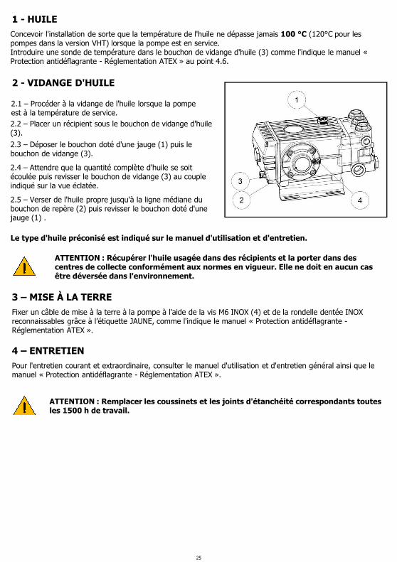
1 - HUILE
2 - VIDANGE D'HUILE
Concevoir l'installation de sorte que la température de l'huile ne dépasse jamais 100 °C (120°C pour les pompes dans la version VHT) lorsque la pompe est en service.Introduire une sonde de température dans le bouchon de vidange d'huile (3) comme l'indique le manuel « Protection antidéflagrante - Réglementation ATEX » au point 4.6.
2.1 – Procéder à la vidange de l'huile lorsque la pompe est à la température de service.2.2 – Placer un récipient sous le bouchon de vidange d'huile (3).
2.3 – Déposer le bouchon doté d'une jauge (1) puis le bouchon de vidange (3).
2.5 – Verser de l'huile propre jusqu'à la ligne médiane du bouchon de repère (2) puis revisser le bouchon doté d'une jauge (1) .
2.4 – Attendre que la quantité complète d'huile se soit écoulée puis revisser le bouchon de vidange (3) au couple indiqué sur la vue éclatée.
ATTENTION : Récupérer l'huile usagée dans des récipients et la porter dans des centres de collecte conformément aux normes en vigueur. Elle ne doit en aucun cas être déversée dans l'environnement.
Le type d'huile préconisé est indiqué sur le manuel d'utilisation et d'entretien.
3 – MISE À LA TERRE
Fixer un câble de mise à la terre à la pompe à l'aide de la vis M6 INOX (4) et de la rondelle dentée INOX reconnaissables grâce à l’étiquette JAUNE, comme l'indique le manuel « Protection antidéflagrante -Réglementation ATEX ».
4 – ENTRETIENPour l'entretien courant et extraordinaire, consulter le manuel d'utilisation et d'entretien général ainsi que le manuel « Protection antidéflagrante - Réglementation ATEX ».
ATTENTION : Remplacer les coussinets et les joints d'étanchéité correspondants toutes les 1500 h de travail.
25

1 - ÖL
2 - ÖLWECHSEL
Richten Sie die Anlage so ein, dass eine Öltemperatur von 100°C (120°C für Pumpen in VHT-Ausführung) beim Betrieb der Pumpe auf keinen Fall überschritten wird.Führen Sie gemäß Angaben unter 4.6. der Anleitung "ATEX-Explosionsschutz" einen Temperaturfühler in den Ölablassverschluss (3) ein.
2.1 – Nehmen Sie den Ölwechsel bei Pumpe auf Betriebstemperatur vor.2.2 – Stellen Sie einen Behälter unter den Ölablassverschluss (3).
2.3 – Entfernen Sie den Verschluss mit Ölmessstab (1) und anschließend den Ölablassverschluss (3).
2.5 – Füllen Sie neues Öl bis auf halbe Höhe des Ölstandverschlusses (2) und schrauben Sie den Verschluss mit Messstab (1) fest.
2.4 – Warten Sie, bis die gesamte Ölfüllung ausgelaufen ist, schrauben Sie dann den Ölablassverschluss (3) auf das in de Explosionszeichnung angegebene Anzugsmoment fest.
ACHTUNG: Altöl muss in geeigneten Behältern gesammelt und gemäß einschlägigen Bestimmungen den entsprechenden Wertstoffstellen zugeführt werden. Es darf auf keinen Fall in die Umwelt abgeleitet werden.
Verwenden Sie die in der allgemeinen Betriebs- und Wartungsanleitung angegebene Ölsorte.
3 – ERDUNG
Hierzu müssen Sie anhand der GELB etikettierten Edelstahlschraube M6 (4) und Zahnscheibe ein Erdungskabel an die Pumpe befestigen, siehe Anleitung "ATEX-Explosionsschutz”.
4 – WARTUNGFür die ordentliche und außerordentliche Wartung verweisen wir auf die allgemeine Betriebs- und Wartungsanleitung sowie auf die Anleitung "ATEX-Explosionsschutz”.
ACHTUNG: Wechseln Sie Lager und entsprechende Dichtringe alle 1500 Betriebsstunden aus.
26

1 - ACEITE
2- CAMBIO DE ACEITE
Preparar la instalación de manera que la temperatura del aceite no supere nunca los 100 °C (120°C para las bombas en la versión VHT) cuando la bomba esté funcionando.Introducir una sonda de temperatura dentro del tapón del aceite (3) como se indica en el punto 4.6 del manual de “Protección antideflagrante ATEX”.
2.1 – El cambio de aceite se debe efectuar cuando la bomba está a la temperatura de trabajo.2.2 – Colocar un recipiente debajo del tapón de descarga del aceite (3).
2.3 – Quitar el tapón con varilla (1) y, a continuación, el tapón de descarga (3).
2.5 – Llenar con aceite nuevo hasta que el nivel alcance la mediana del tapón indicador (2) y, a continuación, enroscar el tapón con varilla (1).
2.4 – Esperar a que el aceite se vacíe por completo antes de enroscar el tapón de descarga (3) con el par de apriete que se indica en el dibujo de despiece.
ATENCIÓN: Recoger el aceite agotado en un recipiente y entregarlo en un centro de eliminación de residuos como previsto por la normativa vigente. No verter en el medio ambiente.
Para saber qué tipo de aceite se debe utilizar, consultar el manual general de uso y mantenimiento.
3 – PUESTA A TIERRA
Es necesario fijar un cable de puesta a tierra a la bomba a través del tornillo M6 de acero inoxidable (4) y la arandela dentada de acero inoxidable indicados en la etiqueta AMARILLA, como figura en el manual de “Protección antideflagrante ATEX”.
4 – MANTENIMIENTOPara más información sobre el mantenimiento ordinario y extraordinario, consultar el manual general de uso y mantenimiento y el manual de “Protección antideflagrante ATEX”.
ATENCIÓN: Sustituir los cojinetes y los anillos de estanqueidad cada 1500 horas de trabajo.
27

1 - ÓLEO
2 - TROCA DE ÓLEO
Organize a instalação, de tal modo que não supere, de forma alguma, os 100°C (120°C para bombas na versão VHT) de temperatura do óleo durante o funcionamento da bomba.Use uma sonda de temperatura para ser inserida no interior do tampão de descarga do óleo (3), conforme indicado no manual "Proteção contra explosão ATEX", no ponto 4.6.
2.1. - A troca do óleo é realizada com bomba de temperatura de trabalho.2.2 – Posicione um recipiente abaixo do tampão de descarga do óleo (3).
2.3 – Remova o tampão com haste (1) e, sucessivamente, o tampão de descarga (3).
2.5 – Preencha com óleo novo até atingir o meio do tampão da luz do nível de óleo (2) e aperte o tampão com haste (1).
2.4 – Aguarde até que todo o óleo tenha saído, em seguida, aperte o tampão de descarga (3) com o torque indicado no desenho expandido.
ATENÇÃO: O óleo desgastado deve ser coletado em recipientes e descartado nos centros adequados, de acordo com as normas vigentes. Não deve ser, de forma nenhuma, disposto no meio ambiente.
Para o tipo de óleo a usar, consulte o indicado no manual de uso e manutenção genérico.
3 – ATERRAMENTO
É necessário fixar um cabo de aterramento na bomba, através dos parafusos M6 INOX (4) e a arruela serrilhada de INOX, devidamente assinalada pela etiqueta AMARELA, conforme indicado no manual "Proteção contra explosão ATEX".
4 – MANUTENÇÃOPara a manutenção ordinária e extraordinária, veja o manual de uso e manutenção genérico e o manual "Proteção contra explosão ATEX".
ATENÇÃO: Substitua os rolamentos e os relativos anéis de vedação a cada 1500 horas de funcionamento.
28

DICHIARAZIONE UE DI CONFORMITA’(Ai sensi dell’allegato X della Direttiva Europea 2014/34/UE - ATEX)
Il produttore INTERPUMP GROUP S.p.A. - Via E. Fermi, 25 - 42049 S. ILARIO D’ENZA (RE) - ItaliaDICHIARA sotto la propria esclusiva responsabilità che le pompe identificate e descritte come segue :
Denominazione : POMPA SERIE 47 Tipo : Pompa alternativa a pistoni per acqua ad alta pressioneMarchio di fabbrica : INTERPUMP GROUP Modelli : WS133; WS171; WS101; WS131; WS151; WS201; WS251; WS92; WS162; WS132
WS82; WS102; WS152; WS202; WS252; WS1630; WS1625; W913; W921; W928T9281; W912; W916; W914; W922; TS1636; TS1630; HT4715; HT4718; HT4718HT4721;VHT4715; VHT4718; VHT4721; VHT4723; SSE2013; SSE2015; SSE1518SSE2021; SSU2015; SSU2018; SSU1521
F/T : 47-ATX
Contrassegnate con gruppo II, categoria 2 GD, protezione EPL Gb/Db e con classe di temperatura T4/T135°C, quando ordinate come pompe ATEX, risultano essere conformi alla Direttiva 2014/34/UE ATEX e possono essere utilizzate in atmosfera potenzialmente esplosiva nei limiti delle zone classificate, nell’osservanza delle prestazioni dichiarate ed installate e utilizzate nel rispetto delle indicazioni del presente libretto, di quello generale e/o di quello specifico di ogni pompa.
II 2G Ex h IIC T4 GbII 2G Ex h IIIC T135°C Db
Il produttore utilizza tutte le misure necessarie per garantire che le pompe prodotte siano conformi a quanto dichiarato.
Norme europee applicate :UNI EN 1127-1:2011; UNI CEI ISO 80079-36:2016; UNI CEI ISO 80079-37:2016
Firma :
Fascicolo tecnico depositato presso DNV ITALIA ( N° 2460)
Il responsabile
Reggio Emilia, Novembre/2017
29

UE DECLARATION OF CONFORMITY(Pursuant to Annex X of the European Directive 2014/34/UE - ATEX)
The manufacturer INTERPUMP GROUP S.p.A. - Via E. Fermi, 25 - 42049 S.ILARIO D’ENZA (RE) - ItalyDECLARES under its sole responsibility that the pumps identified and described as follows:
Name : SERIES 47 PUMP Type : Reciprocating plunger pump for high pressure waterTrademark : INTERPUMP GROUP Models : WS133; WS171; WS101; WS131; WS151; WS201; WS251; WS92; WS162; WS132; WS82; WS102
WS152; WS202; WS252; WS1630; WS1625; W913; W921; W928; T9281; W912; W916; W914W922; TS1636; TS1630; HT4715; HT4718; HT4718; HT4721;VHT4715; VHT4718; VHT4721VHT4723; SSE2013; SSE2015; SSE1518; SSE2021; SSU2015; SSU2018; SSU1521
F/T : 47-ATX
Marked with group II, category 2 GD, EPL Gb/DB protection and temperature class T4/T135°C, when ordered as ATEX pumps, they are in conformity with the ATEX Directive 2014/34/UE and can be used in potentially explosive atmospheres within the limits of classified areas, in compliance with the declared performance and installed and used in accordance with the guidelines of this manual, of the general manual and/or the specific manual of each pump.
II 2G Ex h IIC T4 GbII 2G Ex h IIIC T135°C Db
The manufacturer uses all measures necessary to ensure that the pumps are produced in accordance with the statements.
European standards applied :UNI EN 1127-1:2011; UNI CEI ISO 80079-36:2016; UNI CEI ISO 80079-37:2016
Signature :
The technical file is deposited at DNV ITALIA ( N° 2460)
Manager
Reggio Emilia, November/2017
30

DÉCLARATION UE DE CONFORMITÉ(Aux termes de l’annexe X de la Directive européenne 2014/34/UE - ATEX)
Le fabricant INTERPUMP GROUP S.p.A. - Via E. Fermi, 25 - 42049 S.ILARIO D’ENZA (RE) - ItalieDÉCLARE, sous sa responsabilité exclusive, que les pompes identifiées et décrites ci-après :
Désignation : POMPE SÉRIE 47Type : Pompe alternative à pistons pour eau à haute pressionMarque : INTERPUMP GROUP Modèle : WS133; WS171; WS101; WS131; WS151; WS201; WS251; WS92; WS162; WS132; WS82
WS102; WS152; WS202; WS252; WS1630; WS1625; W913; W921; W928; T9281; W912W916; W914; W922; TS1636; TS1630; HT4715; HT4718; HT4718; HT4721;VHT4715VHT4718; VHT4721; VHT4723; SSE2013; SSE2015; SSE1518; SSE2021; SSU2015; SSU2018SSU1521
F/T : 47-ATX
Marquage groupe II, catégorie 2 GD, protection EPL Gb/Db et classe de température T4/T135°C, commandées comme pompes ATEX, elles résultent conformes à la Directive 2014/34/UE ATEX et peuvent être utilisées en atmosphère potentiellement explosible dans les limites des zones classées, dans le respect des performances déclarées, et installées et utilisées conformément aux indications fournies dans ce manuel, du manuel général et/ou du manuel spécifique à chaque pompe.
II 2G Ex h IIC T4 GbII 2G Ex h IIIC T135°C Db
Le fabricant utilise toutes les mesures nécessaires pour garantir que ses pompes soient conformes aux déclarations.
Normes européennes appliquées :UNI EN 1127-1:2011; UNI CEI ISO 80079-36:2016; UNI CEI ISO 80079-37:2016
Signature :
Fascicule technique déposé auprès de DNV ITALIA (N° 2460)
Le responsable
Reggio Emilia, Novembre/2017
31

UE-KONFORMITÄTSERKLÄRUNG(Gemäß Anhang X der Europäischen Richtlinie 2014/34/UE- ATEX)
Der Hersteller INTERPUMP GROUP S.p.A. - Via E. Fermi, 25 - 42049 S.ILARIO D’ENZA (RE) - ItalienERKLÄRT eigenverantwortlich, dass die wie folgt identifizierten und beschriebenen Pumpen:
Bezeichnung: PUMPE SERIE 47 Typ: Kolbenhubpumpe für HochdruckwasserHerstellermarke: INTERPUMP GROUP Modell: WS133; WS171; WS101; WS131; WS151; WS201; WS251; WS92; WS162; WS132; WS82
WS102; WS152; WS202; WS252; WS1630; WS1625; W913; W921; W928; T9281; W912W916; W914; W922; TS1636; TS1630; HT4715; HT4718; HT4718; HT4721; VHT4715VHT4718; VHT4721; VHT4723; SSE2013; SSE2015; SSE1518; SSE2021; SSU2015; SSU2018SSU1521
F/T : 47-ATX
Gekennzeichnet mit Gruppe II, Kategorie 2 GD, Schutz EPL Gb/Db und mit Temperaturklasse T4/T135°C, soweit als ATEX-Pumpen bestellt, die Richtlinie 2014/34/UE ATEX erfüllen und im Rahmen der klassifizierten Zonen, der erklärten Leistungen und einer den Angaben in diesem Datenblatt, in der allgemeinen bzw. pumpenspezifischen Anleitung entsprechenden Installation sowie Verwendung in explosionsgefährdeter Umgebung verwendet werden können.
II 2G Ex h IIC T4 GbII 2G Ex h IIIC T135°C Db
Der Hersteller trifft alle erforderlichen Maßnahmen, um die Konformität der hergestellten Pumpen mit der geleisteten Erklärung sicherzustellen.
Angewandte europäische Normen :UNI EN 1127-1:2011; UNI CEI ISO 80079-36:2016; UNI CEI ISO 80079-37:2016
Unterschrift :
Relevante technische Unterlagen bei DNV ITALIA (Nr. 2460) hinterlegt.
Der Geschäftsführer
Reggio Emilia, November/2017
32

DECLARACIÓN UE DE CONFORMIDAD(De acuerdo con el anexo X de la Directiva Europea 2014/34/UE - ATEX)
El fabricante INTERPUMP GROUP S.p.A. - Via E. Fermi, 25 - 42049 S.ILARIO D’ENZA (RE) - ItaliaDECLARA bajo su exclusiva responsabilidad que las bombas identificadas y descritas como se indica a continuación:
Denominación: BOMBA DE LA SERIE 47 Tipo: Bomba alternativa de pistones para agua a alta presiónMarca de fábrica: INTERPUMP GROUP Modelo: WS133; WS171; WS101; WS131; WS151; WS201; WS251; WS92; WS162; WS132; WS82
WS102; WS152; WS202; WS252; WS1630; WS1625; W913; W921; W928; T9281; W912W916; W914; W922; TS1636; TS1630; HT4715; HT4718; HT4718; HT4721; VHT4715VHT4718; VHT4721; VHT4723; SSE2013; SSE2015; SSE1518; SSE2021; SSU2015;SSU2018; SSU1521
F/T : 47-ATX
Marcadas con grupo II, categoría 2 GD, protección EPL Gb/Db y con clase de temperatura T4/T135 °C, cuando se solicitan como bombas ATEX, son conformes con la Directiva 2014/34/UE ATEX y se pueden utilizar en atmósfera potencialmente explosiva dentro de los límites de las zonas clasificadas, siempre y cuando se respeten las prestaciones declaradas e instaladas y se utilicen de acuerdo con cuanto indicado en este folleto, en el manual general y/o en el manual específico de cada bomba.
II 2G Ex h IIC T4 GbII 2G Ex h IIIC T135°C Db
El fabricante aplica todas las medidas necesarias para garantizar la conformidad de las bombas fabricadas con cuanto declarado.
Normas europeas aplicadas :UNI EN 1127-1:2011; UNI CEI ISO 80079-36:2016; UNI CEI ISO 80079-37:2016
Firma :
Fascículo técnico depositado en DNV ITALIA ( N° 2460)
El responsable
Reggio Emilia, Noviembre/2017
33

DECLARAÇÃO UE DE CONFORMIDADE(Nos termos do anexo X da Diretriz Europeia 2014/34/UE - ATEX)
O fabricante INTERPUMP GROUP S.p.a. - Via E. Fermi, 25 - 42049 S.ILARIO D’ENZA (RE) - ItáliaDECLARA sob exclusiva responsabilidade que as bombas identificadas e descritas a seguir:
Denominação: SÉRIE BOMBA DE 47Bomba: Bomba alternativa de pistões para água de alta pressãoMarca registrada: INTERPUMP GROUPModelo: WS133; WS171; WS101; WS131; WS151; WS201; WS251; WS92; WS162; WS132; WS82
WS102; WS152; WS202; WS252; WS1630; WS1625; W913; W921; W928; T9281; W912W916; W914; W922; TS1636; TS1630; HT4715; HT4718; HT4718; HT4721; VHT4715VHT4718; VHT4721; VHT4723; SSE2013; SSE2015; SSE1518; SSE2021; SSU2015;SSU2018; SSU1521
F/T : 47-ATX
Marcada como grupo II, categoria 2 GD, proteção EPL Gb/Db e com classe de temperatura T4/T135°C, quando solicitado como bombas ATEX, parecem estar em conformidade com a Diretriz 2014/34/UE ATEX e pode ser usada em atmosfera potencialmente explosiva, nos limites das áreas classificadas, de acordo com os desempenhos declarados e instalados e usados em relação às indicações do presente folheto, do geral e/ou do específico de cada bomba.
II 2G Ex h IIC T4 GbII 2G Ex h IIIC T135°C Db
O fabricante usa todas as medidas necessárias para garantir que as bombas produzidas estejam conforme o declarado.
Normas europeias aplicadas :UNI EN 1127-1:2011; UNI CEI ISO 80079-36:2016; UNI CEI ISO 80079-37:2016
Assinatura :
Fascículo técnico arquivado em DNV ITALIA (º 2460)
O responsável
Reggio Emilia, Novembro/2017
34

CO
D. 4
7.9
81
1.0
3 –
07
/18
VIA FERMI, 25 42049 S.ILARIO – REGGIO EMILIA (ITALY) TEL.+39 – 0522 - 904311 TELEFAX +39 – 0522 – 904444E-mail: [email protected] - http://www.interpumpgroup.it
Rev
isio
ne
4
INTERPUMPGROUP
Le informazioni presenti su questo documento possono essere variate senza preavviso.
The information contained in this document may change without notice.
Les informations présentes sur ce document peuvent être changées sans besoin de préavis.
Die in diesem Dokument enthaltenen Informationen können ohne Vorankündigung geändert werden.
La información contenida en el presente documento puede modificarse sin previo aviso.
As informações contidas neste documento poderão ser sujeitas a alterações sem aviso prévio.
COPYRIGHT The contents of this booklet are the property of INTERPUMP GROUP. Reproduction and divulgation, in whole or in part, are prohibited by law.
COPYRIGHT Le contenu de cette notice appartient à INTERPUMP GROUP : aux termes de la loi il est interdit de le reproduire et/ou de le divulguer, même partiellement.
COPYRIGHT Der Inhalt dieser Bedienungsanleitung ist Eigentum von INTERPUMP GROUP. Die auch nur teilweise Reproduktion und/oder Verbreitung ist gesetzlich verboten.
COPYRIGHT El contenido del presente manual es propiedad de INTERPUMP GROUP y está legalmente prohibida su reproducción y/o divulgación parcial o total.
COPYRIGHT Il contenuto di questo libretto è di proprietà di INTERPUMP GROUP, ne è vietata la riproduzione e/o la divulgazione, anche parziale, a termini di legge.
COPYRIGHT O conteúdo deste livro é de propriedade da INTERPUMP GROUP, e é proibida a sua reprodução e/ou a sua divulgação, mesmo parcial, nos termos da lei.