45842711-simulink-cdma
6
Simulink Implementation of a CDMA Smart Antenna System MOSTAFA HEFNAWI Department of Electrical and Computer Engineering Royal Military College of Canada Kingston, Ontario, K7K 7B4 CANADA Abstract: - The main objective of this paper is to develop a new software testbed to aid our research on various smart antenna (SA) technologies proposed for future generation wireless communication systems. These models can be used as a platform to test the use of DSPs/FPGs in new generation CDMA-SA systems and will allow to evaluate the array pattern (AP) and the Bit Error Rate (BER) performance over a range of communication channel conditions, e.g., whether the fading is flat or frequency selective, and how much interference the user is getting from other users. This goal is achieved through modeling and simulation using the rapid prototyping environment based on Mathworks Simulink [5]. BER and AP performances are evaluated for different models under various channel conditions to demonstrate the merits of the combined CDMA-SA system. Key-Words: - Smart antenna, Beamforming, DS-CDMA, Simulink, Rapid prototyping. 1 Introduction Multipath fading and system capacity limitations are major hurdles in the delivery of 3G data rates and services as envisioned in IMT-2000 [1]-[2]. Limits on RF spectrum allocation means that there is only a finite bandwidth in which a wireless system can operate, as such, increasing data rates and system capacity by increasing bandwidth is not an option. Further complicating the issue, CDMA techniques require strict power management and using a higher transmitting power, as a method of improving link performance is not a viable option. Recently there has been much interest in CDMA schemes that use Smart Antenna (SA) technology in 3G high-speed applications [3]-[4]. What makes this SA concept such an exciting prospect is the possibility of offering more efficient power control and reduced transmitting power which translates into increased coverage, increased system capacities and support for higher data rates. These SA systems can automatically track the desired signal and null the interfering signal by adjusting the gain and phase of weights, which control the output array element. Therefore, with combined CDMA-SA techniques, Multiple Access Interference (MAI) and multipath fading issues faced by CDMA systems are mitigated by the higher reception sensitivity and interference cancellation benefits of SA techniques, without impacting on the strict requirement for power control in CDMA systems. The main objective of this paper is to develop a new software testbed to aid our research on various smart antenna (SA) technologies proposed for future generation wireless CDMA systems. This goal is achieved through modeling and simulation using the rapid prototyping environment based on Mathworks Simulink [5]. Simulink provides a block diagram interface that is built on core MATLAB numeric, graphic, and programming functionalities. Simulink was chosen primarily for its collection of application-specific blocks that support multiple design disciplines, including 150 physical-layer communication system blocks for broadband wireless, broadcasting and satellite systems; and more specific to this work, an excellent “real world” mobile wideband CDMA model in the form of a complete UMTS WCDMA system operating over a multipath fading channel. However, the major design effort revolved around this study is the creation of new blocks that implement the different modules of a smart antenna system, namely, the antenna array and the adaptive algorithm blocks. These new created subsystems allow extending the capability of Simulink beyond the canned functionality of generic blocksets. 2 System Model A practical layout for implementation of CDMA-SA system using a P-element linear antenna array is depicted in Fig. 1. The user data are transmitted using MPSK modulation and spread using direct sequence CDMA (DS-CDMA) technique. Each user in the CDMA system is assigned a unique pseudorandom code sequence. The signals are received by the antenna array, despread and multiplied by the adaptation complex weight.
-
Upload
oscar-cruz -
Category
Documents
-
view
47 -
download
2
description
Como usar Simulin para CDMA
Transcript of 45842711-simulink-cdma

Simulink Implementation of a CDMA Smart Antenna System
MOSTAFA HEFNAWI Department of Electrical and Computer Engineering
Royal Military College of Canada Kingston, Ontario, K7K 7B4
CANADA
Abstract: - The main objective of this paper is to develop a new software testbed to aid our research on various smart antenna (SA) technologies proposed for future generation wireless communication systems. These models can be used as a platform to test the use of DSPs/FPGs in new generation CDMA-SA systems and will allow to evaluate the array pattern (AP) and the Bit Error Rate (BER) performance over a range of communication channel conditions, e.g., whether the fading is flat or frequency selective, and how much interference the user is getting from other users. This goal is achieved through modeling and simulation using the rapid prototyping environment based on Mathworks Simulink [5]. BER and AP performances are evaluated for different models under various channel conditions to demonstrate the merits of the combined CDMA-SA system. Key-Words: - Smart antenna, Beamforming, DS-CDMA, Simulink, Rapid prototyping. 1 Introduction Multipath fading and system capacity limitations are major hurdles in the delivery of 3G data rates and services as envisioned in IMT-2000 [1]-[2]. Limits on RF spectrum allocation means that there is only a finite bandwidth in which a wireless system can operate, as such, increasing data rates and system capacity by increasing bandwidth is not an option. Further complicating the issue, CDMA techniques require strict power management and using a higher transmitting power, as a method of improving link performance is not a viable option. Recently there has been much interest in CDMA schemes that use Smart Antenna (SA) technology in 3G high-speed applications [3]-[4]. What makes this SA concept such an exciting prospect is the possibility of offering more efficient power control and reduced transmitting power which translates into increased coverage, increased system capacities and support for higher data rates. These SA systems can automatically track the desired signal and null the interfering signal by adjusting the gain and phase of weights, which control the output array element. Therefore, with combined CDMA-SA techniques, Multiple Access Interference (MAI) and multipath fading issues faced by CDMA systems are mitigated by the higher reception sensitivity and interference cancellation benefits of SA techniques, without impacting on the strict requirement for power control in CDMA systems. The main objective of this paper is to develop a new software testbed to aid our research on various smart antenna (SA) technologies proposed for future
generation wireless CDMA systems. This goal is achieved through modeling and simulation using the rapid prototyping environment based on Mathworks Simulink [5]. Simulink provides a block diagram interface that is built on core MATLAB numeric, graphic, and programming functionalities. Simulink was chosen primarily for its collection of application-specific blocks that support multiple design disciplines, including 150 physical-layer communication system blocks for broadband wireless, broadcasting and satellite systems; and more specific to this work, an excellent “real world” mobile wideband CDMA model in the form of a complete UMTS WCDMA system operating over a multipath fading channel. However, the major design effort revolved around this study is the creation of new blocks that implement the different modules of a smart antenna system, namely, the antenna array and the adaptive algorithm blocks. These new created subsystems allow extending the capability of Simulink beyond the canned functionality of generic blocksets.
2 System Model A practical layout for implementation of CDMA-SA system using a P-element linear antenna array is depicted in Fig. 1. The user data are transmitted using MPSK modulation and spread using direct sequence CDMA (DS-CDMA) technique. Each user in the CDMA system is assigned a unique pseudorandom code sequence. The signals are received by the antenna array, despread and multiplied by the adaptation complex weight.

Fig. 1 Block diagram of a CDMA-SA System The weighted signals are then summed to form the array output. The receiver is equipped with a P-element linear antenna array. The received baseband signal at the p-th element of the antenna array output (before despreading operation) is given by
)()()()(1 1
,,,, tnatstbtx pK
k
L
llk
plklkklkk
p +−−= ∑ ∑= =
αττ (1)
where L is the number of paths for each user, )(mbk is the k-th user’s data symbol, lk ,α is the
complex fading coefficient for the l-th path of the k-th user, )(tsk is the spreading waveform of the k-th user, lk ,τ is the time delay of the l-th path of the k-
th user. )(tn p is an additive White Gaussian Noise (AWGN). p
lka , is the p-th entity of the k-th user’s array response vector in the impinging direction
lk ,θ of the l-th path,
lka , =Τ−−−
⎥⎦⎤
⎢⎣⎡ lklk
Pjj ee ,,sin)1(sin .......1
θπθπ (2)
The k-th user’s spreading waveform is
∑=
=N
nkk thncts
1)()()( (3)
where N
nk nc1
)(=
is the k-th user's spreading code, N
is the processing gain and )(th is a rectangular chip pulse in the interval ],0[ cT . In order to pick out the desired user’s signal, a digital matched filter containing the PN code 1c is
applied to each element of the array to provide the sampled output )(my p . For simplicity, we assume that the paths from each mobile reach the antenna array with the same Direction Of Arrival (DOA), i.e. klk θθ =, . The beamformer needs to provide the desired user (k=1) with a beamforming weight vector to adjust the gain and the phase of the array to form the beam towards 1θ ,
1θw [ ]Τ= Pwww ......21 (4) The antenna array output can then be expressed as
=)(my Hw1θ )(my (5)
Where ])(.............)()([)( 21 mymymymy P= (6)
3 Simulink Implementation of
CDMA-SA Fig.2 shows the CDMA-SA Simulink model created in this study. The model can be divided into five main modules: Transmitter, Channel, Receiver, Interfering Users and Control/Display. Moreover, Given that the response of a bandpass system to a bandpass signal is identical to the response of the equivalent baseband system to the equivalent baseband signal, all modeling in this paper was done at the baseband because modeling at the baseband level is much simpler and faster than modeling at the bandpass level.
Data
MPSK
Spread
Desired user
*1w
*4w
*3w
*2w
Despread
Despread
Despread
Despread
Px
xx
M
2
1
∑
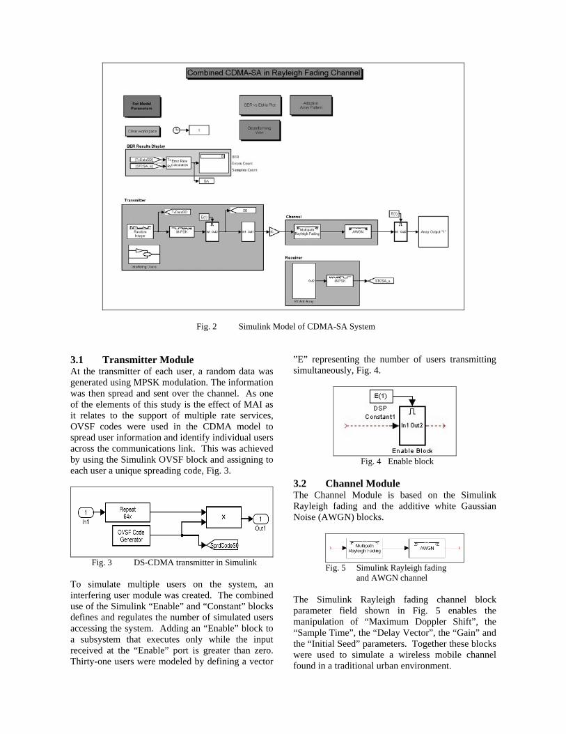
Fig. 2 Simulink Model of CDMA-SA System
3.1 Transmitter Module At the transmitter of each user, a random data was generated using MPSK modulation. The information was then spread and sent over the channel. As one of the elements of this study is the effect of MAI as it relates to the support of multiple rate services, OVSF codes were used in the CDMA model to spread user information and identify individual users across the communications link. This was achieved by using the Simulink OVSF block and assigning to each user a unique spreading code, Fig. 3.
Fig. 3 DS-CDMA transmitter in Simulink
To simulate multiple users on the system, an interfering user module was created. The combined use of the Simulink “Enable” and “Constant” blocks defines and regulates the number of simulated users accessing the system. Adding an “Enable” block to a subsystem that executes only while the input received at the “Enable” port is greater than zero. Thirty-one users were modeled by defining a vector
”E” representing the number of users transmitting simultaneously, Fig. 4.
Fig. 4 Enable block
3.2 Channel Module The Channel Module is based on the Simulink Rayleigh fading and the additive white Gaussian Noise (AWGN) blocks.
Fig. 5 Simulink Rayleigh fading
and AWGN channel The Simulink Rayleigh fading channel block parameter field shown in Fig. 5 enables the manipulation of “Maximum Doppler Shift”, the “Sample Time”, the “Delay Vector”, the “Gain” and the “Initial Seed” parameters. Together these blocks were used to simulate a wireless mobile channel found in a traditional urban environment.

Fig. 6 Simulink Rayleigh Fading Channel Block
By defining the number of reflected multipath components and their relative delays and powers it was possible to define whether the channel is undergoing flat or frequency selective fading. 3.3 Receiver Module Based on the operation of an SA system as described in the introduction the beamforming component was implemented by creating two subsystems, an antenna array subsystem and an adaptive processing subsystem. • Antenna Array Implementation A Simulink “Complex Phase Shift” block was used to produce phase shifted versions of the signal that represented the copies of the signal that would be incident on each element at the receiver, as shown in Fig. 7. It was then possible to define the impinging angles of each signal from the individual users transmitting across the channel from the perspective of each receiver array element by using Simulink “Go To” blocks. • Adaptive Processing Implementation The adaptive processing component of the SA technique was implemented using the Simulink Least Mean-Square (LMS) blocks, Fig. 8. The LMS algorithm was chosen for its simplicity and the fact that it could sufficiently model the adaptive processing component of the SA system for the purposes of this study.
Fig. 7 Simulink implementation of a
linear antenna array
Fig. 8 SA adaptive algorithm Block
• Display and Control Modules The two-performance criterions used to gauge the system performance are the Bit-Error-Rate (BER) and the adaptive antenna array pattern (AP). The Control/Display Module consists of the “Set Model Parameters”, the “Array Pattern Plot”, the “BER vs. Eb/No Plot”, and the “BER Results Display”. The parameters used to define the model simulation scenarios, i.e. those defined in the “Set Model Parameter” block are summarized in Table 1.

Table 1 Model Parameters
PARAMETER Description Flat
Fading Frequency Selective
PG processing gain 64,
128, 256
64, 128, 256
Delay Vector
Relative delay between the signal of interest and the delayed version arriving at the receiver where Tc = Chip period.
[0 Tc] [0 10*Tc]
Gain Vector (dB)
The relative gain that is assigned to the signal of interest and the delayed version.
[0 –5] [0 –5]
Doppler (Hz)
Positive scalar representing the maximum Doppler shift.
10 10
4 Simulation Results For this study, the following assumptions were made: 1) each user was given unique user code; 2) there is a perfect power control; 3) a 2-ray fading channel; and 3) a slow fading channel, i.e. the Doppler effect was minimal. 4.1 Simulation results of CDMA model
without smart antenna Fig. 9 shows the BER performance of the CDMA model (without SA) for different processing gains (PGs) over a flat and a frequency selective fading channels.
0 2 4 6 8 10 1210 -4
10 -3
10 -2
10 -1
10 0
Eb/No (dB)
BE
R
C
PG=64PG=128PG=256
Flat Fading
Frequency Selective Fading
Fig. 9 BER performance of CDMA system over
flat and frequency selective fading channels It is shown that increasing the PG results in a better performance across the flat fading channel and does
not result in any significant improvement in performance over a frequency selective channel. Moreover, it is noted that in the frequency selective case there was an overall degradation in link performance caused by Inter-Symbol Interference (ISI) distortions. This validation results accurately reflect the expected behavior of a CDMA system operating in a multipath fading environment. Validation of the ability of the CDMA model (without SA) to simulate the effects of MAI is shown in Fig. 10. It is noted that increasing the number of interfering users results in a degradation in the system performance. This impairment in the system performance is mainly due to the loss of orthogonality caused by the multipath fading channel. These results validate the model’s ability to simulate the MAI effects.
0 2 4 6 8 10 12 14 16 18 2010-4
10-3
10-2
10-1
100
Eb/No (dB)
CDMA Bit Error Probability Plot
2 Users14 Users22 Users30 Users
BER
Fig. 10 CDMA Model BER Performance Plot for
Multiple Users
4.2 Simulation Results of the combined CDMA-SA Model
The CDMA-SA model was run using the parameters defined in Table 2. Fig. 11 and Fig. 12 show array patterns with signal’s DOA of 20 and 40 degrees, respectively. For both DOAs it is shown that the main lobe is oriented toward the desired signal’s DOA and nulls have been created towards interferers’ DOAs. In other words, the adaptive antenna array is able to track the signals of interest and reduce the effect of multipath fading and interferences.

Table 2 CDMA-SA Model Parameters
PARAMETER VALUE Antenna Array Elements 16 PG 64 Delay Vector [0 Tc/10] Gain Vector (dB) [0 –5] Doppler (Hz) 10 Desired User DOA (degrees) 20o and 40o Interfering Users DOA Vector (degrees) [30 -60 -50 -40 -30 -20 -10 0 10]
Eb/No (dB) 0 –20 for the BER and 0 dB for the array pattern plots
-60 -40 -20 0 20 40 60 80 100-60
-50
-40
-30
-20
-10
0
Angle [Deg.]
Gai
n (d
B)
Fig. 11 Array patterns for signal’s DOA=20 deg.
-60 -40 -20 0 20 40 60 80 100-80
-70
-60
-50
-40
-30
-20
-10
0
Angle [Deg.]
Gai
n (d
B)
Fig. 12 Array patterns for signal’s DOA=40 deg.
On the other hand, Fig. 13 shows a BER performance comparison of the CDMA-SA and the CDMA only systems under MAI condition with 30 interferers. It is shown that the combined CDMA-SA technique, when compared with the CDMA only technique, performed better in environments with an SNR <20dB. However, as the SNR increases the performance gains fell to that delivered by the CDMA technique.
0 2 4 6 8 10 12 14 16 18 2010
-2
10-1
100
Eb/No (dB)
CDMACDMA-SA
BER
Fig. 13 BER Performance Comparison of CDMA-
SA and CDMA systems with 30 MAI 5 Conclusion The main goals of this paper were to implement a CDMA and CDMA-SA wireless schemes in a Simulink environment and use these models to evaluate their performance. The main purpose of the CDMA model was to provide a baseline reference for performance and system capacity so that an assessment of the effectiveness of the smart antenna technique could be made. Through simulation it was shown that, in environments with an SNR <20dB, the combined CDMA-SA technique provided superior performance at higher system loads, providing substantial improvement in link performance and system capacities, above that possible with the traditional CDMA technique. References: [1] M.R. Karim, and Mohsen Sarraf, W-CDMA
and cdma2000 for 3G Mobile Networks, McGraw-Hill, 2002.
[2] Tero Ojanperä and Ramjee Prasan, Wideband CDMA for Third Generation Mobile Communications, Artech House1998.
[3] J. Liberti and T.S. Rapparport, Smart Antennas for Wireless Communications: IS-95 & 3G CDMA, Englewood Cliffs, NJ, Prentice Hall, 1999.
[4] M. Hefnawi, G. Y. Delisle, “Smart Antenna System for Wideband CDMA Signals ,” IEEE International Symposium on Antenna and Propagation , July 2001, pp. 22-25.
[5] The MathWorks Inc., http://www.mathworks.com.