4.5” Suspension Systembds-suspension.com/instructions/014446.pdf4.5” Suspension System Jeep...
16
4.5” Suspension System Jeep Wrangler JK | 2007-2014 Rev. 081414 491 W. Garfield Ave., Coldwater, MI 49036 . Phone: 517-279-2135 • Web/live chat: www.bds-suspension.com . E-mail: [email protected] BDS PART #014446
Transcript of 4.5” Suspension Systembds-suspension.com/instructions/014446.pdf4.5” Suspension System Jeep...
4.5” Suspension System
Jeep Wrangler JK | 2007-2014
Rev. 081414
491 W. Garfield Ave., Coldwater, MI 49036 . Phone: 517-279-2135 • Web/live chat: www.bds-suspension.com . E-mail: [email protected]
BDS PART #014446
2 | 014446
Read And Understand All Instructions And Warnings Prior To Installation Of System And Operation Of Vehicle.
FOR YOUR SAFETYCertain BDS Suspension products are intended to improve off-road performance. For your safety and the safety of your passengers, take the following precautions.
• HANDLING - Modified vehicles will likely handle differently than a factory equipped vehicle.
• ROLLOVERS - Extreme care must be used to prevent loss of control or vehicle rollover.
• DRIVE SAFELY - If you do fail to drive your modified vehicle safely, it may result in serious injury or death.
• DON’T MIX SYSTEMS - We do not recommend the combined use of suspension lifts, body lifts, or other lifting devices.
• STAY SOBER - You should never operate your modified vehicle under the influence of alcohol or drugs.
• OBEY THE LAW - Always drive your modified vehicle at reduced speeds to ensure your ability to control your vehicle under all driving conditions. Always wear your seat belt.
RECOMMENDATIONS• PROFESSIONAL INSTALLATION - BDS Suspension recommends that this system be installed by a professional technician.
• PROFESSIONAL KNOWLEDGE - Disassembly/reassembly procedures and post installation checks must be known to install this system.
• SPECIAL LITERATURE REQUIRED - OE Service Manual for model/year of vehicle. Refer to manual for proper disassembly/reassembly procedures of OE and related components.
• OE RECOMMENDATIONS - Adhere to recommendations when replacement fasteners, retainers and keepers are called out in the OE manual.
• LARGER RIM AND TIRE COMBINATIONS - These may increase leverage on suspension, steering, and related components. When selecting combinations larger than OE, consider the additional stress you could be inducing on the OE and related components.
• DRIVE LINE VIBRATION - After installation vehicles may experience drive line vibrations. Angles may require tuning, slider on shaft may require replacement, shafts may need to be lengthened or trued, and U-joints may need to be replaced.
• SHOP SAFETY - Secure and properly block vehicle prior to installation of components. Always wear safety glasses when using power tools.
• WITH A HOIST - If installation is to be performed without a hoist, we recommend rear alterations first.
• AMOUNT OF LIFT - Due to payload options and initial ride height variances, the amount of lift is a base figure. Final ride height dimensions may vary in accordance to original vehicle attitude. Always measure the attitude prior to beginning installation.
AFTER THE INSTALLATION, BEFORE YOU DRIVE• Check all fasteners for proper torque.
• Checktoensureforadequateclearancebetweenallrotating,mobile,fixed,andheatedmembers.
• Verifyclearancebetweenexhaustandbrakelines,fuellines,fueltank,floorboardsandwiringharness.
• Checksteeringgearforclearance.Testandinspectbrakesystem.
• Performsteeringsweeptoensurefrontbrakehoseshaveadequateslackanddonotcontactanyrotating,mobileorheatedmembers.
• Inspectrearbrakehosesatfullextensionforadequateslack.
• Failuretoperformhosecheck/replacementmayresultincomponentfailure.
• Longerreplacementhoses,ifneededcanbepurchasedfromalocalpartssupplier.
• Performheadlightcheckandadjustment.
• Re-torqueallfastenersafter500miles.Alwaysinspectfastenersandcomponentsduringroutineservicing.
NOTAPPLICABLETOALLBDSSUSPENSIONSYSTEMS
014446 | 3
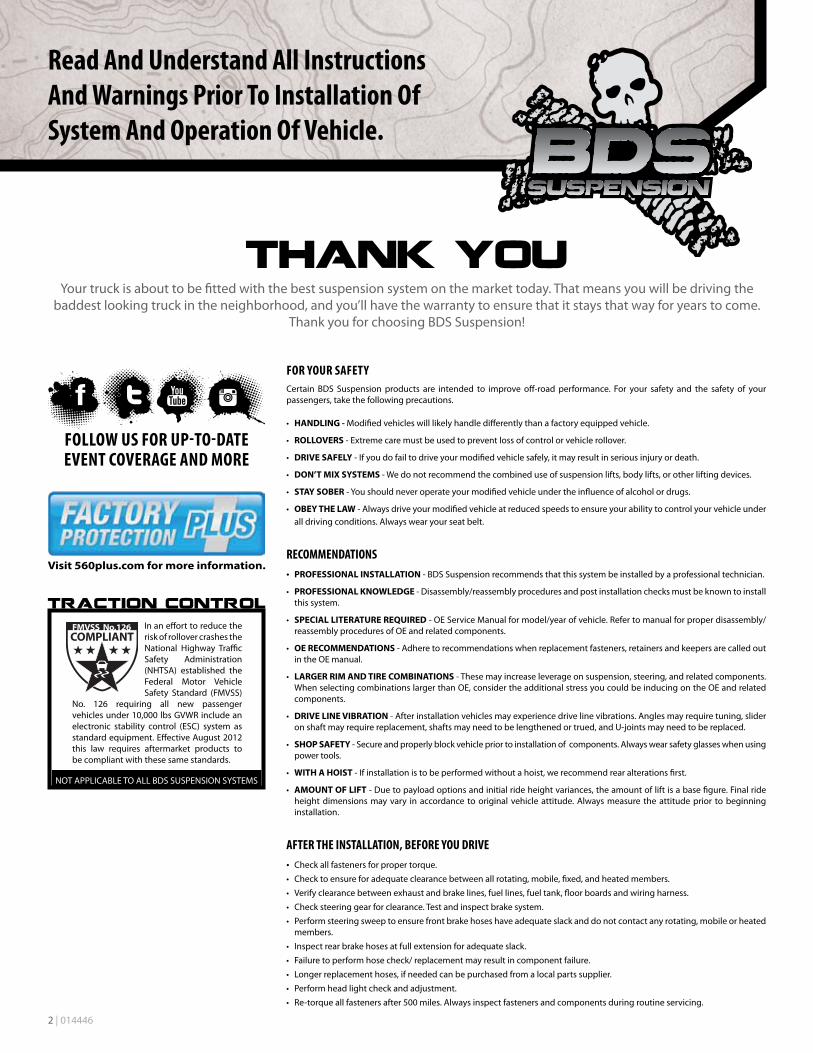
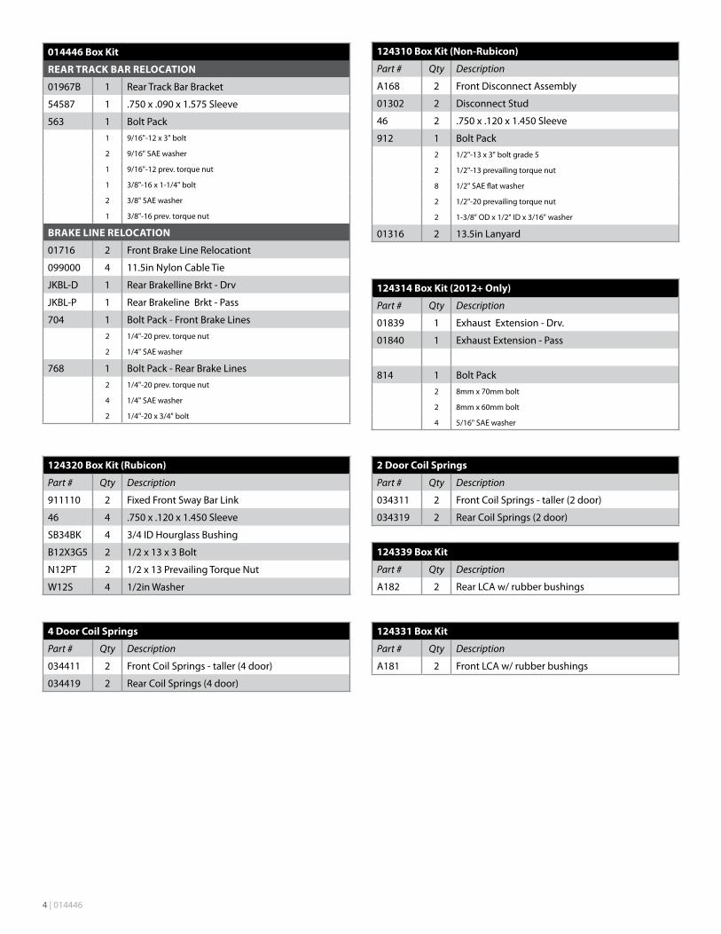
014446 Box Kit
FRONT TRACK BAR RELOCATION BRACKET
01964B 1 Front Track Bar Bracket
69 1 .75x.083x1.375Sleeve
01393B 1 Support Bracket
562 1 BoltPack2 7/16"-14 x 1" bolt
3 7/16" SAE washer
2 7/16"-14 prev. torque nut
1 9/16"-12 x 3" bolt
2 9/16” SAE washer
1 9/16”-12 prev. torque nut
1 1/2"-13 square nut
1 1/2"-13 x 1" bolt
1 1/2" SAE washer
645 1 BoltPack1 9/16"-12 x 3-1/2" bolt
2 9/16" SAE washer
1 9/16"-12 prev. torque nut
2 3/8"-16x1-1/4"bolt
4 3/8"SAEwasher
2 3/8"-16prev.torquenut
014446 Box Kit
Part # Qty Description
084402R 1 DroppedPitmanArm
W96S 4 Trans. Skid Spacer Washer
A187 2 Rear Adjustable Flex UCA
Front and Rear Bump Stops
3396 2 3in x 3in Front Extension
438 1 FrontBumpStopBoltPack1 3/8"-16x1-1/4"self-tappingbolt
2 3/8"USSwasher
2 3/8"-16x3-1/2"bolt
763 1 RearBumpStopBoltPack2 5/16"-18x1-1/4"bolt
2 5/16"-18x7/8"bolt
4 5/16"-18prev.torquenut
8 5/16"SAEwasher
01928B 2 Rear Bump Stop Extension
REAR SWAY BAR LINKS
92025 2 Sway Bar Extension
SB58BK 4 5/8IDHourglassBushing
62147 4 .625x.075x1.375Sleeve
758 1 BoltPack2 12mm-1.75x60mmbolt
2 12mm-1.75prev.torquenut
4 1/2" SAE washer
#1425H-4”LiftKitShownwithOptionalAdjustableLowerControlArms
4 | 014446
124310 Box Kit (Non-Rubicon)
Part # Qty Description
A168 2 Front Disconnect Assembly
01302 2 Disconnect Stud
46 2 .750x.120x1.450Sleeve
912 1 BoltPack2 1/2"-13x3"boltgrade5
2 1/2"-13 prevailing torque nut
8 1/2" SAE flat washer
2 1/2"-20 prevailing torque nut
2 1-3/8"ODx1/2"IDx3/16"washer
01316 2 13.5inLanyard
124320 Box Kit (Rubicon)
Part # Qty Description
911110 2 FixedFrontSwayBarLink
46 4 .750x.120x1.450Sleeve
SB34BK 4 3/4IDHourglassBushing
B12X3G5 2 1/2 x 13 x 3 Bolt
N12PT 2 1/2x13PrevailingTorqueNut
W12S 4 1/2in Washer
124314 Box Kit (2012+ Only)
Part # Qty Description
01839 1 Exhaust Extension - Drv.
01840 1 ExhaustExtension-Pass
814 1 BoltPack2 8mmx70mmbolt
2 8mmx60mmbolt
4 5/16"SAEwasher
124339 Box Kit
Part # Qty Description
A182 2 RearLCAw/rubberbushings
2 Door Coil Springs
Part # Qty Description
034311 2 Front Coil Springs - taller (2 door)
034319 2 Rear Coil Springs (2 door)
4 Door Coil Springs
Part # Qty Description
034411 2 Front Coil Springs - taller (4 door)
034419 2 Rear Coil Springs (4 door)
124331 Box Kit
Part # Qty Description
A181 2 FrontLCAw/rubberbushings
014446 Box Kit
REAR TRACK BAR RELOCATION
01967B 1 Rear Track Bar Bracket
54587 1 .750x.090x1.575Sleeve
563 1 BoltPack1 9/16"-12 x 3" bolt
2 9/16" SAE washer
1 9/16"-12 prev. torque nut
1 3/8"-16x1-1/4"bolt
2 3/8"SAEwasher
1 3/8"-16prev.torquenut
BRAKE LINE RELOCATION
01716 2 FrontBrakeLineRelocationt
099000 4 11.5inNylonCableTie
JKBL-D 1 Rear Brakelline Brkt - Drv
JKBL-P 1 RearBrakelineBrkt-Pass
704 1 BoltPack-FrontBrakeLines2 1/4"-20 prev. torque nut
2 1/4" SAE washer
768 1 BoltPack-RearBrakeLines2 1/4"-20 prev. torque nut
4 1/4" SAE washer
2 1/4"-20 x 3/4" bolt
014446 | 5
PRE-INSTALLATION NOTES1. Stock wheels cannot be re-installed due to interference with the rear sway bar links.
2. If Fox 2.0 series shocks are being installed. BDS front (104002) and rear (104006) stainless steel brake lines are recommended.
INSTALLATION INSTRUCTIONS1. Parkthevehicleonaclean,flatsurfaceandblocktherearwheelsforsafety.
2. Measure from the center of the wheel up to the bottom edge of the wheel opening and record below:
LF______RF______LR______RR______
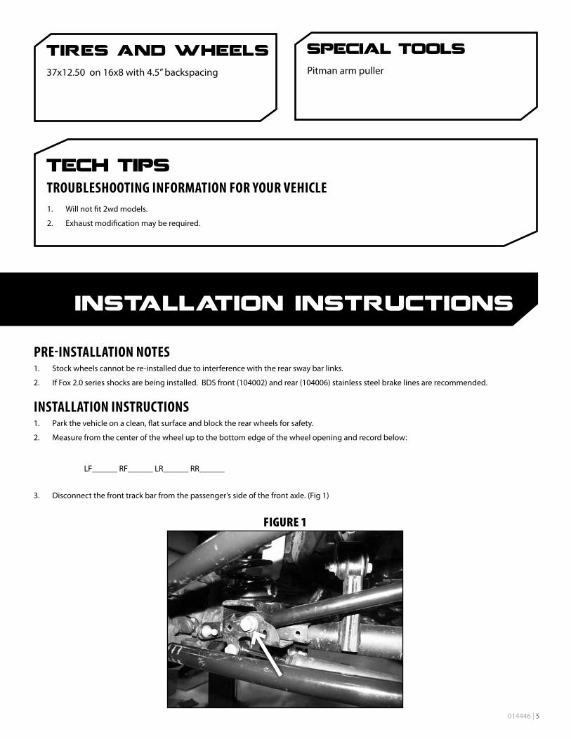
3. Disconnect the front track bar from the passenger’s side of the front axle. (Fig 1)
Figure 1
37x12.50on16x8with4.5”backspacing Pitmanarmpuller
1. Will not fit 2wd models.
2. Exhaust modification may be required.
6 | 014446
4. Raise the front of the vehicle and support the frame with jack stands behind the front lower control arm pockets.
5. Remove the wheels. Remove the 3 bolts mounting the transmission skid plate and remove it from the vehicle.
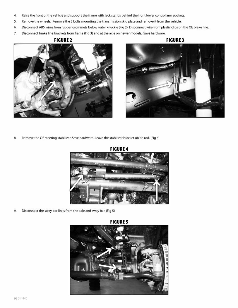
6. Disconnect ABS wires from rubber grommets below outer knuckle (Fig 2). Disconnect wire from plastic clips on the OE brake line.
7. Disconnect brake line brackets from frame (Fig 3) and at the axle on newer models. Save hardware.
Figure 2
Figure 3
8. RemovetheOEsteeringstabilizer.Savehardware.Leavethestabilizerbracketontierod.(Fig4)
Figure 4
9. Disconnecttheswaybarlinksfromtheaxleandswaybar.(Fig5)
Figure 5
014446 | 7
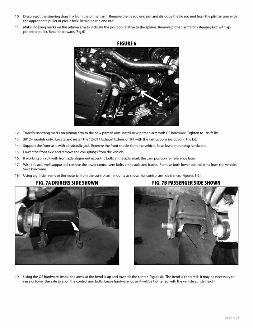
10. Disconnect the steering drag link from the pitman arm. Remove the tie rod end nut and dislodge the tie rod end from the pitman arm with the appropriate puller or pickle fork. Retain tie rod end nut.
11. Make indexing marks on the pitman arm to indicate the position relative to the splines. Remove pitman arm from steering box with ap-propriate puller. Retain hardware. (Fig 6)
Figure 6
12. Transferindexingmarksonpitmanarmtothenewpitmanarm.InstallnewpitmanarmwithOEhardware.Tightento185ft-lbs.
13. 2012+modelsonly:Locateandinstallthe124314ExhaustExtensionKitwiththeinstructionsincludedinthekit.
14. Support the front axle with a hydraulic jack. Remove the front shocks from the vehicle. Save lower mounting hardware.
15. Lowerthefrontaxleandremovethecoilspringsfromthevehicle.
16. IfworkingonaJKwithfrontaxlealignmenteccentricboltsattheaxle,markthecampositionforreferencelater.
17. With the axle well supported, remove the lower control arm bolts at the axle and frame. Remove both lower control arms from the vehicle. Save hardware.
18. Using a grinder, remove the material from the control arm mounts as shown for control arm clearance. (Figures 1-2).
Fig. 7a Drivers siDe showN
Fig. 7b PasseNger siDe showN
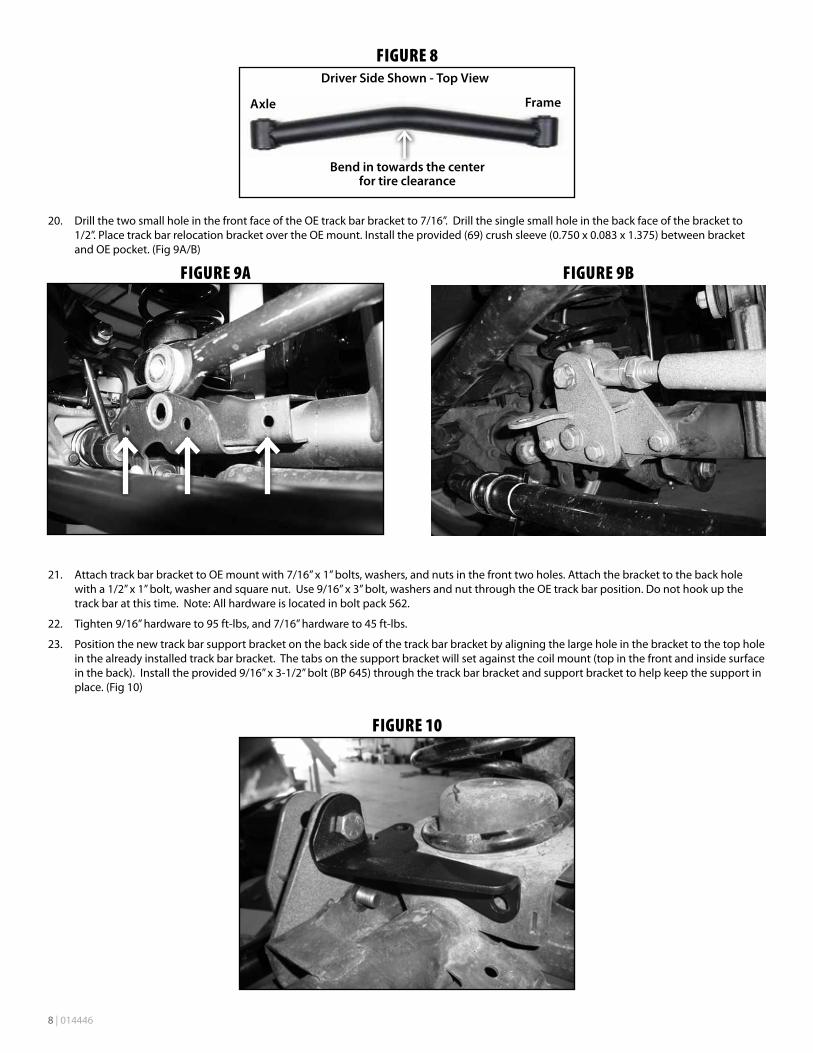
19. UsingtheOEhardware,installthearmssothebendisupandtowardsthecenter(Figure8).Thebendiscentered.Itmaybenecessarytoraiseorlowertheaxletoalignthecontrolarmbolts.Leavehardwareloose,itwillbetightenedwiththevehicleatrideheight.
8 | 014446
Figure 8
Axle
Bend in towards the center for tire clearance
Driver Side Shown - Top View
Frame
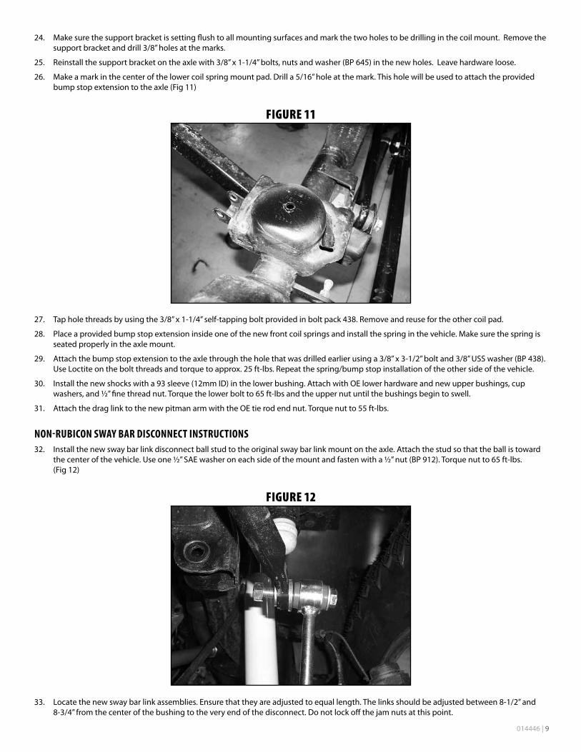
20. Drill the two small hole in the front face of the OE track bar bracket to 7/16”. Drill the single small hole in the back face of the bracket to 1/2”.PlacetrackbarrelocationbracketovertheOEmount.Installtheprovided(69)crushsleeve(0.750x0.083x1.375)betweenbracketand OE pocket. (Fig 9A/B)
Figure 9a
Figure 9b
21. Attach track bar bracket to OE mount with 7/16” x 1” bolts, washers, and nuts in the front two holes. Attach the bracket to the back hole with a 1/2” x 1” bolt, washer and square nut. Use 9/16” x 3” bolt, washers and nut through the OE track bar position. Do not hook up the trackbaratthistime.Note:Allhardwareislocatedinboltpack 562.
22. Tighten9/16”hardwareto95ft-lbs,and7/16”hardwareto45ft-lbs.
23. Positionthenewtrackbarsupportbracketonthebacksideofthetrackbarbracketbyaligningthelargeholeinthebrackettothetopholein the already installed track bar bracket. The tabs on the support bracket will set against the coil mount (top in the front and inside surface intheback).Installtheprovided9/16”x3-1/2”bolt(BP645)throughthetrackbarbracketandsupportbrackettohelpkeepthesupportinplace. (Fig 10)
Figure 10
014446 | 9
24. Make sure the support bracket is setting flush to all mounting surfaces and mark the two holes to be drilling in the coil mount. Remove the supportbracketanddrill3/8”holesatthemarks.
25. Reinstallthesupportbracketontheaxlewith3/8”x1-1/4”bolts,nutsandwasher(BP645)inthenewholes.Leavehardwareloose.
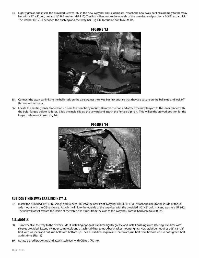
26. Makeamarkinthecenterofthelowercoilspringmountpad.Drilla5/16”holeatthemark.Thisholewillbeusedtoattachtheprovidedbump stop extension to the axle (Fig 11)
Figure 11
27. Tapholethreadsbyusingthe3/8”x1-1/4”self-tappingboltprovidedinboltpack438.Removeandreusefortheothercoilpad.
28. Placeaprovidedbumpstopextensioninsideoneofthenewfrontcoilspringsandinstallthespringinthevehicle.Makesurethespringisseated properly in the axle mount.
29. Attachthebumpstopextensiontotheaxlethroughtheholethatwasdrilledearlierusinga3/8”x3-1/2”boltand3/8”USSwasher(BP438).UseLoctiteontheboltthreadsandtorquetoapprox.25ft-lbs.Repeatthespring/bumpstopinstallationoftheothersideofthevehicle.
30. Install the new shocks with a 93 sleeve (12mm ID) in the lower bushing. Attach with OE lower hardware and new upper bushings, cup washers,and½”finethreadnut.Torquethelowerboltto65ft-lbsandtheuppernutuntilthebushingsbegintoswell.
31. AttachthedraglinktothenewpitmanarmwiththeOEtierodendnut.Torquenutto55ft-lbs.
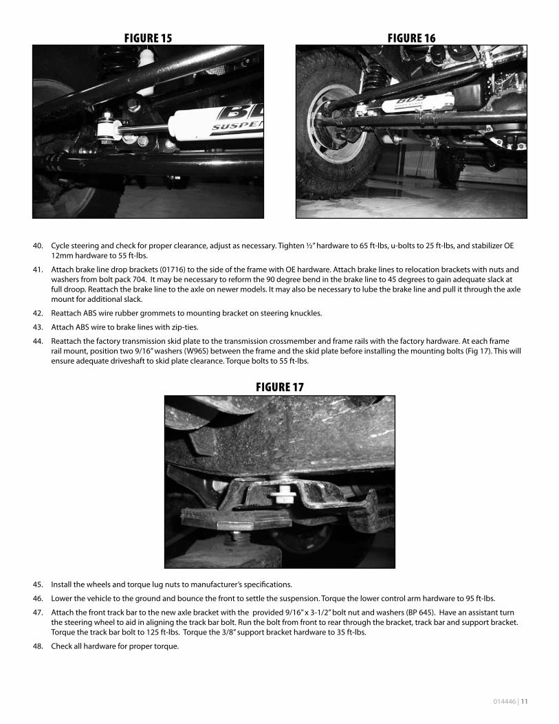
NON-RUBICON SWAY BAR DISCONNECT INSTRUCTIONS32. Install the new sway bar link disconnect ball stud to the original sway bar link mount on the axle. Attach the stud so that the ball is toward
thecenterofthevehicle.Useone½”SAEwasheroneachsideofthemountandfastenwitha½”nut(BP912).Torquenutto65ft-lbs.(Fig 12)
Figure 12
33. Locatethenewswaybarlinkassemblies.Ensurethattheyareadjustedtoequallength.Thelinksshouldbeadjustedbetween8-1/2”and8-3/4”fromthecenterofthebushingtotheveryendofthedisconnect.Donotlockoffthejamnutsatthispoint.
10 | 014446
34. Lightlygreaseandinstalltheprovidedsleeves(46)inthenewswaybarlinksassemblies.Attachthenewswaybarlinkassemblytotheswaybarwitha½”x3”bolt,nutand½”SAEwashers(BP912).Thelinkwillmounttotheoutsideoftheswaybarandpositiona1-3/8”extrathick1/2”washer(BP912)betweenthebushingandtheswaybar(Fig13).Torque½”boltto65ft-lbs.
Figure 13
35. Connect the sway bar links to the ball studs on the axle. Adjust the sway bar link ends so that they are square on the ball stud and lock off the jam nut securely.
36. Locatetheexistinginnerfenderboltupnearthefrontbodymount.Removetheboltandattachthenewlanyardtotheinnerfenderwiththe bolt. Torque bolt to 10 ft-lbs. Slide the male clip up the lanyard and attach the female clip to it. This will be the stowed position for the lanyard when not in use. (Fig 14)
Figure 14
RUBICON FIxED SWAY BAR LINK INSTALL37. Install the provided 3/4” ID bushings and sleeves (46) into the new front sway bar links (911110). Attach the links to the inside of the OE
axlemountwiththeOEhardware.Attachthelinktotheoutsideoftheswaybarwiththeprovided1/2”x3”bolt,nutandwashers(BP912).The link will offset toward the inside of the vehicle as it runs from the axle to the sway bar. Torque hardware to 60 ft-lbs.
ALL MODELS38. Turn wheel all the way to the driver’s side. If installing optional stabilizer, lightly grease and install bushings into steering stabilizer with
sleeves provided. Extend cylinder completely and attach stabilizer to trackbar bracket mounting tab. New stabilizer requires a ½” x 2-1/2” bolt with washers and nut, run bolt from bottom up. The OE stabilizer requires OE hardware, run bolt from bottom up. Do not tighten bolt atthistime.(Fig15)
39. Rotate tie rod bracket up and attach stabilizer with OE nut. (Fig 16)
014446 | 11
Figure 15
Figure 16
40. Cyclesteeringandcheckforproperclearance,adjustasnecessary.Tighten½”hardwareto65ft-lbs,u-boltsto25ft-lbs,andstabilizerOE12mmhardwareto55ft-lbs.
41. Attach brake line drop brackets (01716) to the side of the frame with OE hardware. Attach brake lines to relocation brackets with nuts and washersfromboltpack704.Itmaybenecessarytoreformthe90degreebendinthebrakelineto45degreestogainadequateslackatfull droop. Reattach the brake line to the axle on newer models. It may also be necessary to lube the brake line and pull it through the axle mount for additional slack.
42. Reattach ABS wire rubber grommets to mounting bracket on steering knuckles.
43. Attach ABS wire to brake lines with zip-ties.
44. Reattach the factory transmission skid plate to the transmission crossmember and frame rails with the factory hardware. At each frame rail mount, position two 9/16” washers (W96S) between the frame and the skid plate before installing the mounting bolts (Fig 17). This will ensureadequatedriveshafttoskidplateclearance.Torqueboltsto55ft-lbs.
Figure 17
45. Install the wheels and torque lug nuts to manufacturer’s specifications.
46. Lowerthevehicletothegroundandbouncethefronttosettlethesuspension.Torquethelowercontrolarmhardwareto95ft-lbs.
47. Attachthefronttrackbartothenewaxlebracketwiththeprovided9/16”x3-1/2”boltnutandwashers(BP645).Haveanassistantturnthe steering wheel to aid in aligning the track bar bolt. Run the bolt from front to rear through the bracket, track bar and support bracket. Torquethetrackbarboltto125ft-lbs.Torquethe3/8”supportbrackethardwareto35ft-lbs.
48. Check all hardware for proper torque.
12 | 014446
REAR INSTALLATION49. Block the front wheels for safety.
50. Mark track bar to indicate which end goes into the frame. Remove the rear track bar from vehicle. Retain hardware.
51. Raise the rear of the vehicle and support the frame with jack stands in front of the lower control arm mounts.
52. Remove the wheels.
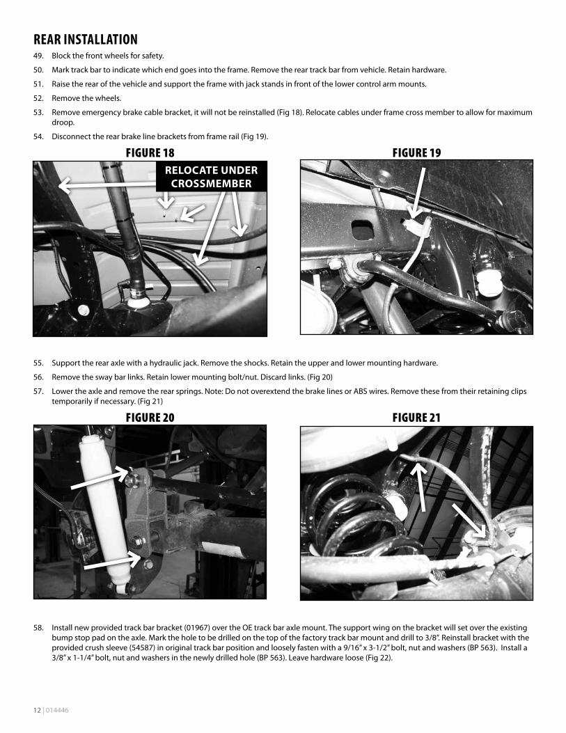
53. Removeemergencybrakecablebracket,itwillnotbereinstalled(Fig18).Relocatecablesunderframecrossmembertoallowformaximumdroop.
54. Disconnect the rear brake line brackets from frame rail (Fig 19).
Figure 18 RELOCATE UNDER
CROSSMEMBER
Figure 19
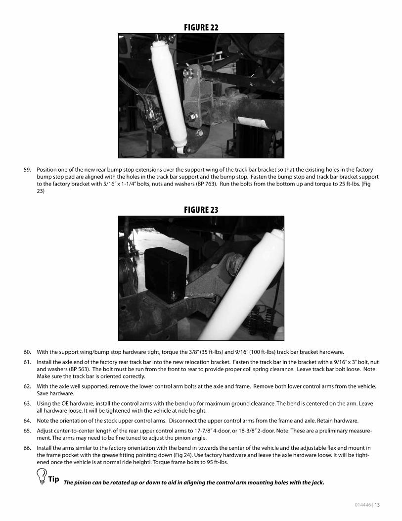
55. Support the rear axle with a hydraulic jack. Remove the shocks. Retain the upper and lower mounting hardware.
56. Remove the sway bar links. Retain lower mounting bolt/nut. Discard links. (Fig 20)
57. Lowertheaxleandremovetherearsprings.Note:DonotoverextendthebrakelinesorABSwires.Removethesefromtheirretainingclipstemporarily if necessary. (Fig 21)
Figure 20
Figure 21
58. Install new provided track bar bracket (01967) over the OE track bar axle mount. The support wing on the bracket will set over the existing bumpstoppadontheaxle.Marktheholetobedrilledonthetopofthefactorytrackbarmountanddrillto3/8”.Reinstallbracketwiththeprovidedcrushsleeve(54587)inoriginaltrackbarpositionandlooselyfastenwitha9/16”x3-1/2”bolt,nutandwashers(BP563).Installa3/8”x1-1/4”bolt,nutandwashersinthenewlydrilledhole(BP563).Leavehardwareloose(Fig22).
014446 | 13
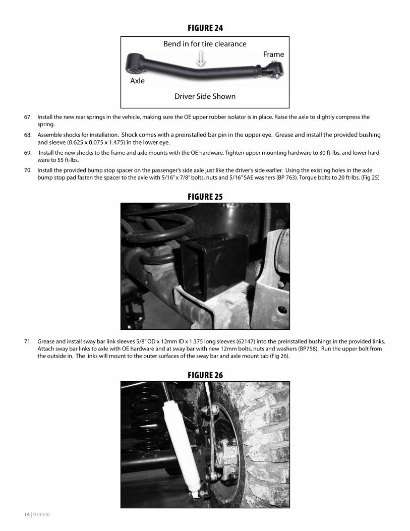
Figure 22
59. Positiononeofthenewrearbumpstopextensionsoverthesupportwingofthetrackbarbracketsothattheexistingholesinthefactorybump stop pad are aligned with the holes in the track bar support and the bump stop. Fasten the bump stop and track bar bracket support tothefactorybracketwith5/16”x1-1/4”bolts,nutsandwashers(BP763).Runtheboltsfromthebottomupandtorqueto25ft-lbs.(Fig23)
Figure 23
60. Withthesupportwing/bumpstophardwaretight,torquethe3/8”(35ft-lbs)and9/16”(100ft-lbs)trackbarbrackethardware.
61. Install the axle end of the factory rear track bar into the new relocation bracket. Fasten the track bar in the bracket with a 9/16” x 3” bolt, nut andwashers(BP563).Theboltmustberunfromthefronttoreartoprovidepropercoilspringclearance.Leavetrackbarboltloose.Note:Make sure the track bar is oriented correctly.
62. With the axle well supported, remove the lower control arm bolts at the axle and frame. Remove both lower control arms from the vehicle. Save hardware.
63. UsingtheOEhardware,installthecontrolarmswiththebendupformaximumgroundclearance.Thebendiscenteredonthearm.Leaveall hardware loose. It will be tightened with the vehicle at ride height.
64. Note the orientation of the stock upper control arms. Disconnect the upper control arms from the frame and axle. Retain hardware.
65. Adjustcenter-to-centerlengthoftherearuppercontrolarmsto17-7/8”4-door,or18-3/8”2-door.Note:Theseareapreliminarymeasure-ment. The arms may need to be fine tuned to adjust the pinion angle.
66. Install the arms similar to the factory orientation with the bend in towards the center of the vehicle and the adjustable flex end mount in the frame pocket with the grease fitting pointing down (Fig 24). Use factory hardware.and leave the axle hardware loose. It will be tight-enedoncethevehicleisatnormalrideheightl.Torqueframeboltsto95ft-lbs.
The pinion can be rotated up or down to aid in aligning the control arm mounting holes with the jack.
14 | 014446
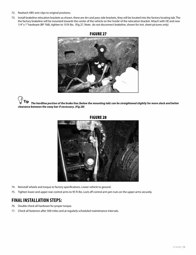
Figure 24
Driver Side Shown
Bend in for tire clearanceFrame
Axle
67. Install the new rear springs in the vehicle, making sure the OE upper rubber isolator is in place. Raise the axle to slightly compress the spring.
68. Assemble shocks for installation. Shock comes with a preinstalled bar pin in the upper eye. Grease and install the provided bushing andsleeve(0.625x0.075x1.475)inthelowereye.
69. Install the new shocks to the frame and axle mounts with the OE hardware. Tighten upper mounting hardware to 30 ft-lbs, and lower hard-wareto55ft-lbs.
70. Install the provided bump stop spacer on the passenger’s side axle just like the driver’s side earlier. Using the existing holes in the axle bumpstoppadfastenthespacertotheaxlewith5/16”x7/8”bolts,nutsand5/16”SAEwashers(BP763).Torqueboltsto20ft-lbs.(Fig25)
Figure 25
71. Greaseandinstallswaybarlinksleeves5/8”ODx12mmIDx1.375longsleeves(62147)intothepreinstalledbushingsintheprovidedlinks.AttachswaybarlinkstoaxlewithOEhardwareandatswaybarwithnew12mmbolts,nutsandwashers(BP758).Runtheupperboltfromthe outside in. The links will mount to the outer surfaces of the sway bar and axle mount tab (Fig 26).
Figure 26
014446 | 15
72. Reattach ABS wire clips to original positions.
73. Install brakeline relocation brackets as shown, there are drv and pass side brackets, they will be located into the factory locating tab. The the factory brakeline will be mounted towards the center of the vehicle on the ‘inside’ of the relocation bracket. Attach with OE and new 1/4”x1”hardware(BP768),tightento10ft-lbs.(Fig27,Note:donotdisconnectbrakeline,shownforinst.sheetpicturesonly)
Figure 27
The hardline portion of the brake line (below the mounting tab) can be straightened slightly for more slack and better clearance between the sway bar if necessary. (Fig 28)
Figure 28
74. Reinstallwheelsandtorquetofactoryspecifications.Lowervehicletoground.
75. Tightenlowerandupperrearcontrolarmsto95ft-lbs.Lockoffcontrolarmjamnutsontheupperarmssecurely.
FINAL INSTALLATION STEPS:76. Double check all hardware for proper torque.
77. Checkallfastenersafter500milesandatregularlyscheduledmaintenanceintervals.
16 | 014446
Thank you for choosing BDS Suspension.For questions, technical support and warranty issues relating to this BDS Suspension product, please contact your distributor/installer
before contacting BDS Suspension directly.