
4321 4325.output
56
* GB784728 (A) Description: GB784728 (A) ? 1957-10-16 Adjusting fabric squeezing rollers in liquid treating machines Description of GB784728 (A) PATENT SPECIFICATION 784,728 f f i Date of Application and filing Complete Specification Aug 4, 1955. No 22484/55. (Patent of Addition to No 629,310 dated March 12, 1947) Complete Specification Published Oct 16, 1957. Index at acceptance: Class 15 ( 1), All. International Classification: -D 06 b. COMPLETE SPECIFICATION Adjusting Fabric Squeezing Rnll W,, Cm SPECIFICA'TON No 784,728 In the heading on page l, for g(patent of Addition to 194 %" 1 read U, (patent of Addition to 1 No 629,5 i O dated ?eb, THE p ATENT OFF Ie 3 ' 4th Februar Y, 1958 , ucscribed _ ireatmg fabrics with liquids, wherein the weighting of the upper nip rollet is effected by hydraulic means, and we further described the utilisation of such hydraulic means to
Transcript of 4321 4325.output

* GB784728 (A)
Description: GB784728 (A) ? 1957-10-16
Adjusting fabric squeezing rollers in liquid treating machines
Description of GB784728 (A)
PATENT SPECIFICATION 784,728 f f i Date of Application and filing Complete Specification Aug 4, 1955. No 22484/55. (Patent of Addition to No 629,310 dated March 12, 1947) Complete Specification Published Oct 16, 1957. Index at acceptance: Class 15 ( 1), All. International Classification: -D 06 b. COMPLETE SPECIFICATION Adjusting Fabric Squeezing Rnll W,, Cm SPECIFICA'TON No 784,728 In the heading on page l, for g(patent of Addition to 194 %" 1 read U,(patent of Addition to 1 No 629,5 i O dated ?eb, THE p ATENT OFF Ie 3 ' 4th Februar Y, 1958 , ucscribed _ ireatmg fabrics with liquids, wherein the weighting of the upper nip rollet is effected by hydraulic means, and we further described the utilisation of such hydraulic means to raise and/or to support the weight of, or to lower on to a fixed support one end of the lower nip roller in order that the bearing at that end of the roller shaft can be removed and a space or gap provided between the rollers to permit of the fabric being introduced or removed We further described how in the case of a machine employing a carrier roller to guide the fabric up to the nip rollers, the hydraulic system can be utilised to support the weight of or to lower on to a fixed support one end of the carrier roller. In certain machines for treating fabrics with liquid, such as milling and scouring machines, in which the fabric is treated in rope form, there are frequently provided in front of the nip rollers, a pair of laterally-spaced vertical rollers between which the rope of fabric passes and which serve to guide the fabric in a correct path between the nip rollers. According to the present invention, pneumatic means are substituted

for the said hydraulic means It will be appreciated, therefore, that where a pump is provided in accordance with our said prior specification, a compressor will now be substituted therefor It has been found that when treating some fabrics, a substantial amount of resilience is neceslPrice 3 s 6 d l 1 o 629,310 12, 19 47) '. dated l March 12, )s 55/:L(Z) /5658 15 o /58 P _, amnine there is u rear of the nip rollers a trough or spout down which the fabric passes and which has a lid pivoted at the end adjacent to the nip 65 rollers and weighted at its free end to cause it to press upon the fabric and retard its progress through the trough The weighting of the trough lid has hitherto been effected by means of dead weights and levers, or by spring 70 means, and also by utilising the hydraulic system as described in our Patent Specification No 646,616 In accordance with the present invention, the weighting may be effected by the pneumatic system referred to above 75 The draft board through which the fabric passes to the nip rollers may also be balanced by pneumatic means. In order that the invention may be clearly understood and readily carried into effect, 80 apparatus incorporating the pneumatic means will now be described, by way of example only, with reference to the accompanying drawings, in which:Figure 1 shows diagrammatically the rele 85 vant parts of a milling or scouring machine. Figure 2 being a detail front view looking in the direction of the arrow 2 in Figure 1. Referring to the drawings, the fabric indicated at a, is led up from the liquid-contain go ing vessel through the usual draft board b and over the carrier roller c to the nip rollers d d', from whence it passes down the usual trough or spout e, this being provided with a lid f pivoted at l' 95 The top roller d of the nip rollers is loaded DB ( PATENT SPECIFICATION 7.4,728 X Date of Application and filing Complete Specification Aug4, 1955. No 22484/55. (Patent of Addition to No 629,310 dated March 12, 1947) \ v t D Complete Specification Published Oct16, 1957. Index at acceptance: Class 15 ( 1), All. International Classification: -DO 6 b. COMPLETE SPECIFICATION Adjusting Fabric Squeezing Rollers in Liquid Treating Machines We, SELLERS & Co (HUDDERSFIELD) LIMITED, of Engine Bridge Works, Chapel Hill, Huddersfield, in the County of York, a Company registered under the Laws of Great Britain, and ERIC ROBERT SELLERS, also of the above address, a British Subject, do hereby

declare the invention, for which we pray that a patent may be granted to us, and the method by which it is to be performed, to be particularly described in and by the following statement:- This invention relates to improvements in or modifications of the invention described and claimed in the specification of our prior Patent No 629,310. in our said prior specification we described a machine for treating fabrics with liquids, wherein the weighting of the upper) nip rollet is effected by hydraulic means, and we further described the utilisation of such hydraulic means to raise and/or to support the weight of, or to lower on to a fixed support one end of the lower nip roller in order that the bearing at that end of the roller shaft can be removed and a space or gap provided between the rollers to permit of the fabric being introduced or removed We further described how in the case of a machine employing a carrier roller to guide the fabric up to the nip rollers, the hydraulic system can be utilised to support the weight of or to lower on to a fixed support one end of the carrier roller. In certain machines for treating fabrics with liquid, such as milling and scouring machines, in which the fabric is treated in rope form, there are frequently provided in front of the nip tollers, a pair of laterally-spaced vertical rollers between which the rope of fabric passes and which serve to guide the fabric in a correct path between the nip rollers. According to the present invention, pneumatic means are substituted for the said hydraulic means It will be appreciated, therefore, that where a pump is provided in accordance with our said prior specification, a compressor will now be substituted therefor It has been found that when treating some fabrics, a substantial amount of resilience is neceslPrice 3 s 6 d l sary in the pressure exerted between the rollers, and as hydraulic means can be regarded as substantially incompressible for most practical purposes, the hydraulic means described in our said specification are not entirely satisfactory The substitution of pneumatic means, however, overcomes this difficulty. Furthermore, the pneumatic means may also be used to enable the distance between the vertical guide rollers to be adjusted, and, if desired, to hold the said rollers yieldingly in position. In a milling or scouring machine there is provided in rear of the nip rollers a trough or spout down which the fabric passes and which has a lid pivoted at the end adjacent to the nip rollers and weighted at its free end to cause it to press upon the fabric and retard its progress through the trough The weighting of the trough lid has hitherto been effected by means of dead weights and levers, or by spring means, and
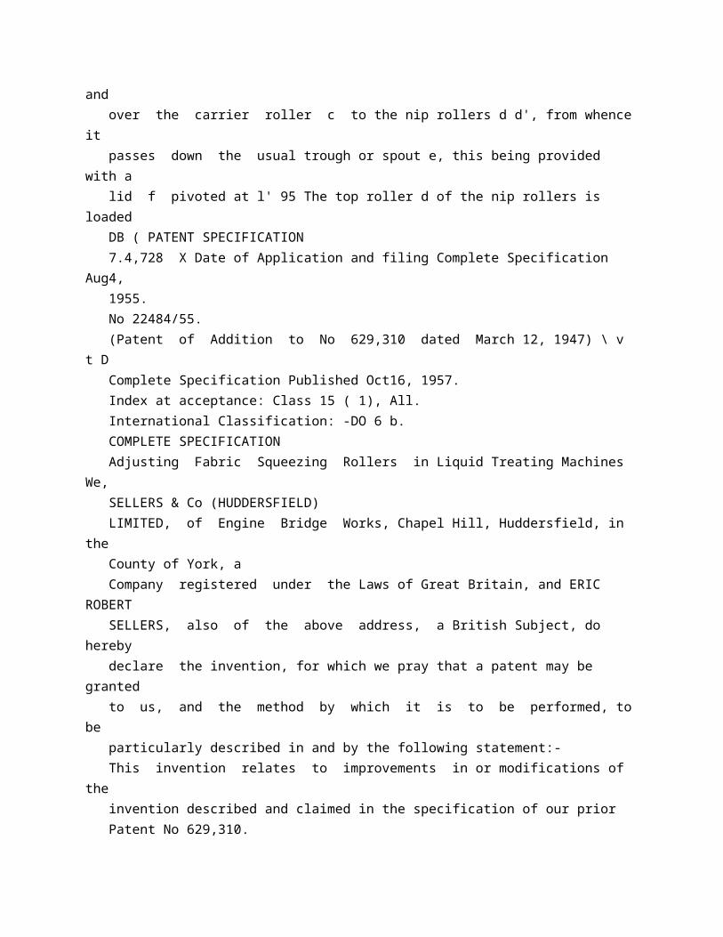
also by utilising the hydraulic system as described in our l Patent Specification No 646,616 In accordance with the present invention, the weighting may be effected by the pneumatic system referred to above. The draft board through which the fabric passes to the nip rollers may also be balanced by pneumatic means. In order that the invention may be clearly understood and readily carried into effect, apparatus incorporating the pneumatic means will now be described, by way of example only, with reference to the accompanying drawings, in which:Figure 1 shows diagrammatically the relevant parts of a milling or scouring machine. Figure 2 being a detail front view looking in the direction of the arrow 2 in Figure 1. Referring to the drawings, the fabric indicated at a, is led up from the liquid-containing vessel through the usual draft board b and over the carrier roller c to the nip rollers d, d', from whence it passes down the usual trough or spout e, this being provided with a lid f pivoted at fl. The top roller d of the nip rollers is loaded 784,728 by means of a lever such as h and pneumatic cylinder i, and the lid f of the trough or spout is loaded by means of a lever j pivoted at j and operated by a pneumatic cylinder k The draft board b is shown as being carried by a lever mn pivoted at mn' and connected to the rod of a piston working in a pneumatic cylinder n, thus enabling the said draft board to be balanced against any desired pressure. Where as is frequently the case, there are provided in front of the nip rollers a pair of laterally-spaced rollers p, p, between which the rope of fabric passes, and which serve to guide the fabric in a correct path between the nip rollers, we arrange as shown in Figure 2, to provide pneumatic cylinders p', p' to enable the distance between such vertical guide rollers to be adjusted and/or to hold them yieldingly in position.
* Sitemap * Accessibility * Legal notice * Terms of use * Last updated: 08.04.2015 * Worldwide Database * 5.8.23.4; 93p
* GB784729 (A)

Description: GB784729 (A) ? 1957-10-16
Improvements in or relating to liquid level indicating system
Description of GB784729 (A)
COMPLETE SPECIFICATION Improvements in or relating to Liquid Level Indicating System We, THE ARO EQUIPMENT CORPORATION, a corporation organised under the laws of the State of Ohio, United States of America, of City of Bryan, State of Ohio, United States of America, do hereby declare the invention, for which we pray that a patent may be granted to us, anvil the method by which it is to be performed, to be particularly described in and by the following statement: This invention relates to a contents gauge for liquid containers, and more particularly to an improved transducer construction in combination with an electrically operated indicator. The present invention relates to a liquid level indicating system comprising a container having liquid therein a transducer responsive to change in hydrostatic pressure in said container, and an indicator electrically responsive to pressure changes in said transducer, said transducer comprising a generally cylindrical housing divided into upper and lower chambers by means of a diaphragm having a thin flexible marginal wall, yieldable means urging said diaphragm downwardly, means connecting said lower chamber with said container, thereby subjecting said diaphragm to hydro static pressure opposing said yieldable means, and a potentiometer mounted in said lower chamber having a wiper actuated by the rise and fall of said diaphragm to vary the flow of current to the indicator. The primary object of the invention is to provide a lightweight, rugged liquid level contents gauge of improved accuracy. Another object is to provide a gauge of this type including a differential pressure transducer having a diaphragm which is extremely sensitive to relatively small pressure changes and so constructed as to withstand excess pressure overloads without adversely affecting the accuracy thereof. Another object is to provide a gauge of this type for use with liquid oxygen containers capable of maintaining its accuracy after continued

exposure to oxygen. Another object is to provide a contents gauge including a transducer having an improved potentiometer that compensates for all non-linearities of the system, including the shape of the tank. A further object is to provide a contents gauge for a liquid oxygen converter system which is adapted to operate at pressures up to 5GO pounds per square inch and over a temperature range of from minus 65 F. to plus 160 F. These and other objects will become apparcnt from the following description when read in conjunction with the accompanying drawings, in which: Figure 1 is a diagrammatic view showing a liquid oxygen tanlr with a liquid level gauge constructed in accordance with the invention in combination therewith; Figure 2 is a transverse sectional view through the transducer constructed in accordance with the invention; Figure 3 is a perspective view of the resis- tance coil employed in rhe potentiometer of the transducer; Figure 4 is an electrical circuit diagram for the gauge of the invention; and Figure 5 is a sectional view through the novel diaphragm employed in the transducer with its normal operating travel shown in broken lines. The gauging system of the invention consists of a low power DC ratiometer indicator and a potentiometer which is actuated by a highly sensitive diaphragm responsive to the hydrostatic head of liquid in the container. The resistance winding of the potentiometer is designed to correct for all system non-linearities. The shape of the tank and the transmissions of the hydrostatic force from one component to another through the entire system contribute to these non-linearities. The combined effects of all of these factors may be determined experimentally. The resistance winding is made on a card or core of such shape as to provide the amount of resistance required to compensate for these non-linearities, thus making the response of the indicator directly proportional to the volume of fluid in the container. The diaphragm in the transducer serves as the motor. The difference in pressure on opposite sides of the diaphragm produces a force proportional to the dilfferential pressure and the active area of the diaphragm. The diaphragm is shaped like a cup, having a flat relatively stiff bottom and an outwardly-flaring thin-Sexi- ble side wall which provides a long travel and negligible spring force. A convolution at the upper edge of the diaphragm rolls up and down the adjacent wall of the transducer housing as the diaphragm travels. The

total force on the diaphragm should be great enough so that all frictional or hysteresis forces are negligible. The area of the diaphragm there fore, must be large enough to produce such a ratio between the differential pressure and the hysteresis or frictional forces. The force developed by the diaphragm acts against a spring which results in compression or displacement. The ideal spring has a displacement that is a linear function of the applied force only and is not dependent upon temperature. The free length of this spring is also critical because this sets the zero reading of the calibration. Since accurate springs are difficult to manufacture, means must be pro- vided for compensating for this deviation and this may be done, as indicated, by varying the resistance of the potentiometer. With all of the non-lineari-ies compensated for, the same applied pressure always preduces the same contact position between the wiper of the potentiometer and the resistance coil over which it slides. Referring to Figure 1, the liquid container designated by the numeral 10 contains liquid in the bottom and gas above the liquid level. In a fuel container the gas might be air or a mixture of air and volatilized fuel. In the particular form of the invention illustrated both the liquid and the gas are oxygen. In order to keep the liquid oxygen in the liquid state the container must be suitably insulated, and preferably is of the double-walled vacuum type. An outlet conduit 12 leads from the liquid phase through the bottom of the container and a conduit 14 connects to the gaseous phase through the top of the container. The pressure differential transducer 20 is mounted in the line 16 wiaich connects at one end to the outlet conduit 12 and at the other end to the conduit 14 near the container. Electrical conductors connect the transducer 20 to the iMi- cator 22 which is preferably a permanent magnet rotor ratiometer. Thus, the indicator 22 may be mounted conveniently at a point remote from the tank and transducer. The indicator connects to a DC power source P, which is grounded. In the power system shown, operation on a 28 volt DC circuit proved to be satisfactory. The transducer 20 is shown in detail in Figure 2 and comprises a housing consisting of an upper shell 30 and a lower shell 32, each having an outwardly extending circumferential -flan,e. The flanges are secured together by means of bolts 34 extending therethrough. The housing is preferably made from lightweight material, such as aluminium, but the walls are heavy enough to withstand the pressure of the system to which the transducer is connected. Weight is particuiarty important where the instrument is designed for use with a liquid container adapted to be mounted in aircr^t. A pressure
sensitive diaphragm 36 is sand-.-t-iched between the flanges of the upper and lov.er shells of the housing and serves as a gasket to seal the space within the housing. The diaphragm divides the housing into an upper chamber and a lower chamber. The r'iai--agm, shown in enlarged view in Figure 5, is moulded into the shape cf a cup, having a bottom 44, outwardly-flaring side wall 42 and an outwardly-extending horizontal flange 35 which is confined between the flanges of the upper and lover shells of the housing, as previously mentioned. The walls of the diaphragm are very thin, preferably around 0.010 inch, to provide a minimum hysteresis loss under flaure. The thickness of the diaphrag ,l may be as low as .005 inch where the container is small, or the differential pressure is low. The flare in the side wall 42 is important since straight sides permit the doubledover portion of the side wall to rub against itself and increase resistance of the diaphragm to pressure. The diaphragm is preferably moulded from a heat setting or vulcanizable material wEch, after vulcanizing, is resilient at temperatures ranging from minus 65 F. to 160 F. For increased strength the diaphragm may be reinforced as with a fabric insert. The resilient material must also be chemically resistant to oxygen (if used with an oxygen container) and it must have a good tensile strength and low permanent set. We prefer to use a silicone rubber composition for diaphragms in liquid oxygen systems since silicone compositions remain flexible over a wide temperature range. These compositions are well known and can be purchased commercially. The silicone compositions are also desirable in that they are highly chemically resistant. Other elasLo-ners, such as natural rubber, are suitable. IIo-:ever, natural rubber will oxidize rather quickly and this necessitates changing the diaphragm frequently. For gasoline systems the elastomer must be of the synthetic variety resistant to hydrocarbons. The interior configuration of the upper shell 30 is critical and is designed to correspond exactly to the cup shape of the diaphragm 36 when inverted. This configuration for the shell protects the diaphragm from damage due to an excess build up of pressure in the lower chamber of the transducer. The normal range of distension below and above the clamped flange 38 is shoovn in Figure 5 in the broken lines. If, for some reason, a sudden surge Of liquid from the container distends the diaphragm beyond the upper limit of its normal travel, no darnage is inflicted because the load is taken by the rigid inner wall of the shell 30, to which the diaphragm conforms precisely. Theoretically, therefore, the over-pressure is limited only by the strength of the housing. The liquid oxygen system illustrated normally operates around 300

pounds per square inch and the transducer housing, therefore, is designed for operation at 500 pounds per square inch, which includes the safety factor. A tapped opening 46 in the top of the upper shell 30 is adapted to connect to the line 16 leading to the gaseous phase in the container, and a similar opening 48 in the bottom of the lower shell 32 is adapted to connect with the line leading to the liquid phase in the container. The gaseous phase, therefore, exerts pressure on the top side of the diaphragm and the liquid phase on the bottom side. In a system where the tank is vented it is not necessary to provide a connection to the upper chamber of the housing. The diaphragm 36 is too thin to be selfsupporting and, consequently, a pair of metal plates 50 and 52 are disposed on either side of the bottom portion 44 of the diaphragm while guide rod 54 maintains the diaphragm coaxial with the housing. The rod 54 is threaded at its lower end, which extends through a central opening in the plates and the diaphragm, and is secured thereto by means of a pair of nuts 60 and 62, one on either side of the upper and lower plates 50 and 52. The upper end of the rod 54 slides in a bearing 64 threadedly engaged in the lower portion of the opening 46. The lower end of the rod 54 screws into a tapped opening in the head 66 of the rod 68, which is adapted to move axially in a bearing 70 mounted within the upper portion of the op en- ing 48. The clearance between the rods 54 and 68 and their respective bearings is sufficient to permit gasified liquid oxygen to flow from the openings 46, 48 to the interior of the housing. Openings of capillary size are employed in connecting the container to the spaces above and below the diaphragm to prevent rapid fluctuations of the indicator needle due to sudden changes in hydrostatic head. It will be understood that separate openings in the housing may be provided instead of the space surrounding shafts 54 and 68. A coil spring 74, within the upper chamber, is secured to the outside diameter of the bearing 64 all its upper end and to the nut 60 at its lower end. This spring is adapted to be compressed by the upward movement of the diaphragm due to differential pressure, or the hydrostatic head. The characteristics of importance for the spring 74 are free length, spring rate and linearity. The free length is determined by the number of coils and their spacing. The spring rate is a function of the number of active turns, coil diameter, wire diameter and modulus of the material. Linearity is affected by any change in the number of active turns, as for example, when some coils collapse on adjacent turns before the end of the stroke. This is particularly true at the ends. The non-linearity thus introduced may be compensated for in the design of

the potentiometer. The potentiometer, which varies the electrical resistance in the circuit in which the indicator 22 is incorporated, consists of a pointer or wiper 110 and a potentiometer card 80. The card 80 consists of a core 88, preferably made of copper so as to permit conducting heat from the coil windings to the shell of the transducer. The core 88 is of such configuration as to vary the length, and consequently the resistance, of the wire wound thereon to compensate for the non-linearity of the system. The type of indicator determines the power requirements of the potentiometer. The wire is made from a high resistance alloy having an insulating coating, and the core 88 is suitably coated with a dielectric varnish before the wire is wound thereon. Conductor taps 100, 102 and 104 connect to the resistance card at the top, the centre and the bottom, respectively, for making connections to the ratiometer 22, as best shown in the wiring diagram of Figure 4. The opposite ends of the taps connect to the inner ends of leads 106 mounted in insulating plugs 108 screwed into tapped holes in the angular wall of the lower shell 32 of the housing. The conductors from the indicator connect to the ends of the leads 106 extending outside the housing. The edge 86 of the resistance winding is scraped bare so as to provide good electric contact and a minimum of friction with the conductive slider or wiper 110 of the potentiometer which travels linearly up and down the resistance in response to differential pressure. The complete circuit shown in Figure 4 is standard for instruments of this nature. The circuit is particularly well adapted for an instrument which is to be used in conjunction with liquid oxygen or other material that tends to corrode the potentiometer windings and, therefore, change the resistance. The particular circuit illustrated in Figure 4 causes the current flowing through each of the three coils C in the ratiometer to be affected equally in the event the resistance is increased, as for example, due to a corrosive film on the conductor. Consequently, the accuracy of the instrument is not adversely affected by considsable contact resistance. The wiper 110 is mounted cantilever fashion on a flat arm 112 fixed to a leaf spring 114 which is secured to the side wall of the shell 32 by means of a lug 116. Thus, the wiper is grounded. A rectangular opening 111 extends through the arm 112 to permit the rod 68 to pass therethrough. Because the arm 112 pivots an the spring 114 there is lateral movement with respect to the rod 68, hence the opening 111 is elongated. The opening also is of smaller width than the diameter of the head 66 and the arm is urged into firm yielding contact with the bottom of the head by the spring 114, thus moving the wiper upwardly as the rod 68 ascends due to pressure on the diaphragm.

OPERATION The unit is designed to measure the volume due to change in the hydrostatic head of the liquid in the container. As the hydrostatic head increases, the liquid oxygen which fills the lower portion of the transducer by flowing through line 12 exerts a pressure on the underside of the diaphragm 36, causing it to rise against the compressive force of spring 74. As the diaphragm rises, the rod 68 rises with it because they are connected through rod 54, and the spring 114 urges the wiper 110 upwardly to keep it in firm contact with the head 66. The single bend or convolution 40 at the top of the diaphragm, as best shown in Figure 5, rolls along the tapered sides of the upper shell 30. It will be understood that the long travel of the diaphragm is not achieved by stretching the material. The construction allows a negligible spring rate for the diaphragm itself since the only energy absorbed is that necessary to form the top bend at the top of the convolution. The normal length of travel is that in which the bend moves from the flange edge 38 and along the flaring side 42 to the bortom portion 44 of the diaphragm. Further travel in either direction will straighten out the bend and introduce restoring forces. Therefore, the normal measuring travel is restricted to the pose'irons where a natural bend is formed, as indicated in Figure 5. Resistance to over-pressure is accomplished by forming the upper shell 30 on the low pressure side to the free shape of the diaphragm. On over-pressure the bend or convolution 40 is straightened out and the diaphragm conforms precisely to the shape of the shell. It will be noted that by reason of the diaphragm design there is a change in effective area as the diaphragm ascends or descends, in accordance with the length of side wall 42 out of contact with the shell. This change in diameter of the effective area can be compensated by appropriately shaping the potentiometer card. As already mentioned, there is also an energy loss due to hysteresis in the diaphragm material at the bend. This hysteresis loss is in effect equivalent to mechanical friction resisting diaphragm motion in either direction. The hysteresis loss ma7 be minimized by employing a very thin material having a composition which is flexible over a wide temperature range, sucn as silicone rubber. In a system having a container adapted to hold 20 liters of liquid oxygen, the change in pressure due tO hydrostatic head will range from zero to 0.6 pounds per square inch. Consequently, the diaphragm must be very sensitive to changes in pressure if it is to travel over the distance indicated to provide a comparatively wide swing of the wiper 110. In large tanks, or where

the liquid in the tank is of high gravity, tliis problem is not so difficult because the range of pressures due to hydrostatic head is much wider. As the diaphragm moves vertically, the wiper 110 slides along the conductive edge 86 of the resistance card 80 to vary the electrical resistance in the circuits containing the ratiometer coils C, Figure 4. The change in resistance modifies the current in the coils, thus causing the indicator needle to swing in the direction of the most highly energized coil. As shown in Figure 1, the indicator needle is adapted to swing through an arc of 180 , zero indicating empty and 180 indicating full. When the wiper is in contact with the top winding af the resistance card 80, the current is proportioned among the three coils in such manner as to cause the needle to rest on the full mark on the indicator dial. When all of the resistance is in the other side of the circuit, the current ratio among the three coils changes so that the needle swings around to the empty mark on the dial. When the wiper contact coincides ;.with the tap 102 at midpoint between tile top and bottom of the resistance card, the indicator needle will stand at 90o, the half-full mark, because in such case the current in each coil is balanced. The small resistance indicated by the letters Rl and R. in Figure 4 are provided to permit adjustment of the indicator needle to the zero degree and 1GO" positions when the tank is empty and full. B7 running the wiper the full length of the card and supplying additional taps at either end, the indicator needle will swing through an arc of 3605. An apparatus constructed in accordance with this invention for use with a 20 liter liquid oxygen container was found to be accurate within plus or minus 2% of the liquid content. Suitable adjustment for the rate and length of the spring 74 may be made by adjusting the position of the lower rod 68 on the upper rod 54. A flat is provided on the end of the rod 68 which projects outside the case to permit adjustment by turning the head 66 up or down on the threaded end of the rod 54. Although we have described our invention primarily with reference to a small container for liquid oxygen, it 5 apparent that the invention is capable of use with other types of containers. It will also be apparent to those skilled in the art that other arrangements of the elements and constructions therefor are possible without departing from the score of the appended claims. What we claim is : 1. A liquid level indicating system comprising a container having a liquid therein, a transducer responsive to change in hydrostatic pressure in said container, and an indicator electrically responsive

to pressure changes in said transducer, said transducer comprising a generally cylindrical housing divided into upper and lower chambers by means of a diaphragm having a thin flexible marginal wall, yieldable means urging said diaphragm downwardly, means connecting said lower chamber with said container, thereby subjecting said diaphragm to hydrostatic pressure opposing said yieldable means, and a potentioz meter mounted in said lower chamber having a wiper actuated by the rise and fall of said diaphragm to vary the flow of current to the indicator. 2. A system according to Claim 1 in which said diaphragm is cup-shaped and said upper chamber has a cup shape corresponding to that of the diaphragm when inverted, the side wall of said cup-shaped diaphragm having a convolution at its upper edge adapted to roll up and down the side wall of said upper chamber as said diaphragm rises and falls due to change in pressure. 3. A system according to Claim 1 wherein said transducer comprises a generally cylindrical housing having an upper and a lower shell, and a cup-shaped diaphragm made from thin rubber4ike material havmg a stiffened bottom, an outwardly flaring side wall and a circumferential flange extending from said side wall and sandwiched between said upper and lower shells, said upper shell having an internal cup shape corresponding to that of the diaphragm when inverted, the side wall of said diaphragm having a convolution at its upper edge adapted to move up and down the side wall of said upper shell as the bottom of the diaphragm rises and falls due to change in pressure. 4. A system according to Claim 1, 2 or 3 in which the liquid in the container is oxygen and the diaphragm is made from a rubber-like compound having low hysteresis loss and good low temperature stability. 5. A system according to any of the preceding claims in which the diaphragm is made from a silicone rubber composition. 6. A system according to any of the preceding claims wherein the potentiometer mounted in said lower chamber has a non-linear variable resistance to compensate for non-linearities in other portions of the system. 7. A liquid level indicating system comprising a container having liquid therein, a transducer responsive to change in hydrostatic pressure in said container and an indicator electrically responsive to pressure changes in said - transducer, said transducer comprising a generally cylindrical housing having an upper and a lower shell, a cup-shaped diaphragm made from thin rubber-like material having a stiffened bottom, an outwardly flaring side wall and a circumferential flange extending from said side wall and sandwiched between said upper and leo'vet shells, said upper shell having gn internal cup shape

corresponding to that of the diaphragm when inverted, the side wall of said diaphragm having a convolution at its upper edge adapted to move up and down the side wall of said upper shell as the bottom of the diaphragm rises and falls due to change in pressure, yieldable means urging said diaphragm bottom downwardly, means connecting said lower chamber with said container, thereby subjecting said diaphragm to hydrostatic pressure opposing said yieldable means, a potentiometer mounted in said lower shell including a wiper arm, said wiper arm being mounted on a leaf spring and having an opening therethrough spaced from said spring, and an axially disposed rod fixed to said diaphragm bottom extending into said lower chamber through said opening in the spring and carrying a stop, said spring biasing said arm upwardly against said stop, whereby the wiper moves up and down with said rod and diaphragm to vary the flow of current to the indicator. 8. A system according to Claim 7 in which said diaphragm bottom is stiffened by a pair of plates, one disposed on either side thereof. 9. A liquid level indicating system
* Sitemap * Accessibility * Legal notice * Terms of use * Last updated: 08.04.2015 * Worldwide Database * 5.8.23.4; 93p
* GB784730 (A)
Description: GB784730 (A) ? 1957-10-16
Controlling means for rotary machines
Description of GB784730 (A)
A high quality text as facsimile in your desired language may be available amongst the following family members:
CH324481 (A) DE1031225 (B) FR1141904 (A) CH324481 (A) DE1031225 (B) FR1141904 (A) less
Translate this text into Tooltip
[83][(1)__Select language] Translate this text into
The EPO does not accept any responsibility for the accuracy of data and information originating from other authorities than the EPO; in particular, the EPO does not guarantee that they are complete, up-to-date or fit for specific purposes.
PATENT SPECIFICATION 784573 O Date of Application and filing Complete Specification Sept 2, 1955. No 25322/55. Application mode in Switzerland on Sept 3, 1954. Application made in Switzerland on Aug 24, 1955. Complete Specification Published Oct 16, 1957. Index at Acceptance:-Classes 23, P 3 A, P 9 D( 1: 3); 65 ( 1), A( 2 A: 2 B: 2 D: 2 F: 6); 80 ( 4), R 1; and ( 3), H 2 DX. International Classification: -BO 4 b E 05 f F 03 b F 06 p. COMPLETE SPECIFICATION Controlling Means for Rotary Machines We, CIBA LIMITED, a body corporate organized according to the laws of Switzerland, of Basle, Switzerland, do hereby declare the invention, for which we pray that a patent may be granted to us, and the method by which it is to be performed, to be particularly described in and by the following statement:- The present invention relates to controlling means for rotary machines. In industry rotary machines are used for various purposes the shafts of which continue to rotate by inertia after the driving force has been interrupted and which have parts, especially covers, which for safety in operation should not be moved, for example opened, until the machines are at a standstill In the following description and claims the word " open " as applied to this part is intended to mean the position which is only desired while the shaft of the machine is stopped The above is a requirement; for example, with some mixing and grinding machines and especially with centrifuges, in the case of which there is considerable danger of injury if opening of the cover can take place during operation The present invention is of especial advantage for use with relatively large centrifuges, which are of wide application in industry and most of which have a fairly heavy cover which owing to its weight is difficult to open by hand In the following description the invention will be considered in greater
detail as applied to centrifuges. In the case of centrifuges it is of importance to maintain the cover closed during operation, not only owing to the possibility of injury to operatives but also on other grounds, for example for avoidance of spraying out of liquids and of penetration of foreign bodies or additional material for centrifuging during the operation, which would lead to unsymmetrical loading and thus to the possibility of damage to the machine A further difficulty arises in the case of centrifuges that when the drive is stopped they would take much too long to come to a standstill if left to themselves so that an lPl effective braking must be employed There is therefore a requirement in the case of centrifuges for a simple and safe means which renders possible a simplification by rendering largely 50 automatic the necessary operations in starting and stopping The present invention provides controlling means for rotary machines the shafts of which continue to rotate by inertia after the driving 55 force has been interrupted and which have a movable part intended to be closed during rotation of the shaft and opened only when the shaft is stopped, said controlling means comprising a fluid pressure system for opening 60 said part and for controlling the closing thereof, means operated by a mechanical connection with the shaft and adapted to interrupt the application of opening fluid pressure while the shaft is rotating and means operated 65 by the fluid pressure used to open said part and by fluid pressure produced in closing said part and adapted to interrupt the supply of motive power to the machine. As operating fluid there can be employed for 70 example in the means provided by the present invention, water from a water supply line A particularly simple modification is provided, however, by the use of compressed air Since in chemical plant compressed air lines are 75 normally available for various purposes, the use of compressed air is generally possible without additional expense. Fluid pressure may be used for both the control and the drive of the machine 80 In conjunction with the means of the present invention, the problem can also be solved advantageously and in a simple manner, of measuring the number of revolutions per minute of a centrifuge This can take place 85 by means of a pump coupled to the shaft of the centrifuge, advantageously a gear pump, which circulates a pressure medium, advantageously oil, in a circuit provided with a restrictor, and a pressure gauge which 90 measures the pressure thereby produced The pressure gauge, which can be a normal mano784,730 meter, is then calibrated so that it gives a direct reading of the number of revolutions per minute of the centrifuge. For driving the centrifuge an electric motor can also be used In view of the difficulty of protecting the motor against the corrosive

influences of the atmosphere and of liquids which may be present, it may be more advantageous to drive the centrifuge with a water turbine, for example of the type of the Pelton turbine Such turbines can easily be provided with a braking device, which may consist for example of a set of turbine blades adapted to drive in the direction contrary to the normal running direction and on which fluid can impinge from a separate nozzle, or more simply by admission of a pressure fluid to the back of the already existing blades through a separate nozzle, or finally by deflecting the driving water stream so as to impinge on to the back of the blades These turbines in addition possess the advantage of entailing no additional danger in spaces subject to the occurrence of explosions, they allow alteration of the speed of rotating during the operation and render possible a large number of startings and stoppings within a particular time interval, because the heat normally produced in braking is dissipated in the water. The present invention is however also applicable when the drive is conducted by means of electric motors using a braking system of known type, for example a mechanical system, or by suitable wiring of the electric motor itself for braking of the centrifuge. In a preferred embodiment of the invention, especially in the case of fluid pressure driven centrifuges, the method of operation for starting and stopping can be particularly simply arranged when two coupled four-way cocks are used of which one controls the raising and lowering of the cover and the other the redirection of the driving energy from driving to braking By a combination of the two control means, the advantage is provided that on the one hand the centrifuge is only opened when it has come to a standstill and that on the other hand a reversal of the direction of rotation of the centrifuge is prevented once it has come to a standstill and the cover is open. The invention is illustrated diagraimmatically in the accompanying drawing in which: Fig 1 shows the lay-out of a centrifuge system with fluid pressure operation and Fig 2 shows the lay-out of a centrifuge system with combined electrical and fluid pressure operation. Referring to Fig 1, a centrifuge is shown at 10 Its cover 11 is provided with a rigidly attached lever 12 and can be pivoted about a shaft 13 The lever 12 is connected by a rod 14 with a piston 16 in a cylinder 15. The drive of the centrifuge takes place by means of a turbine 17 This comprises blades 18, the driving sides of which can be struck by water under pressure from a combined nozzle and valve 19 and the rear sides 20 of which can be struck by water under pressure from a similar nozzle valve 21 The driving nozzle 70 19 is controlled by a piston 25 working in a cylinder 22, and the braking nozzle 21 by a piston 26 working in a cylinder 23 Springs 24 urge the two pistons into the

closed positions of the corresponding valves when the air 75 in the cylinders is not under compression No means are illustrated in Fig 1 for the supply of water for the driving and braking ot the turbine. With the driving shaft is also coupled a 80 gear pump 27 When the centrifuge is in operation, this pumps oil from an oil reservoir 28, through a restrictor 29 and back into the oil reservoir 28 The restrictor operates as a resistance in the oil pumping circuit and the 85 pressure thereby produced is measured by a manometer 30 By suitable calibration of the manometer the number of revolutions per minute of the centrifuge can be read off directly at any particular moment 90 The nozzles 19 and 21 are controlled by compressed air which is transmitted from a supply line 40, by way of an air filter 49, a release valve 33, a four-way cock 31, conduits 41 and 42 respectively and restrictors 36, to 95 th cylinders 22 and 23 respectively. The opening and closing of the cover 11 are likewise effected by compressed air from the supply line 40, transmitted by way of the air filter 49, a four-way cock 32 (which is 100 coupled to the cock 31), and either a valve 35 (which is controlled as described below), a restrictor 37 and a conduit 43 or a conduit 44 respectively to the cylinder 15 A valve 34 is provided which is operated by oil-pressure in 105 the oil line of the manometer 30 by connection with a conduit 45 This valve opens a nozzle 39 when a sufficient oil pressure prevails in the manometer oil line and thus, in conjunction with a variable restrictor 38, pre 110 vents opening of the valve 35. The method of operation of the arrangement shown in Fig 1 is as follows:The indicated positions of the parts, in particular of the four-way cocks 31 and 32, corre 115 spond to the running of the centrifuge Compressed air is conveyed to the cylinder 22 and the valve at 19 is open On the other hand no air pressure is exerted in the cylinder 23 because passage is open through the conduit 120 42 and the cock 31 to the atmosphere The cover is maintained closed under its own weight and owing to the air pressure maintained in the lower part of the cylinder 15 The manometer 30 indicates an oil pressure result 125 ing from rotation of the pump 27. To stop the centrifuge, the coupled fourwray cocks 31 and 32 are turned through 90 ' in a clock-wise direction On account of the pressure prevailing in the oil line of the mano 130 784,730 3 meter, the valve 34 remains open so long as the centrifuge is rotating to any appreciable extent Compressed air passing through the restrictor 38 thus escapes through the nozzle 39 The valve 35 remains closed and thus the cover is not yet lifted nor the valve 33 shifted to the " out " position indicated by a broken line, since the compressed air, re-directed by the cock 32 only proceeds as far as the valve 35 On the other hand the turning of the cock 31 has the immediate effect that
the driving nozzle valve 19 is closed and the braking nozzle valve 21 opened When, as a result of the braking effect, the centrifuge has practically come to a standstill, the valve 34, which has become relieved of pressure, closes and by the closure of the nozzle 39 the controlling pressure at the valve 35 rises until the valve 35 opens Compressed air from the supply line 40 now passes by way of the turned cock 32 through the restrictor 37 on the one hand into the pressure control line of the release valve 33 and on the other hand by way of the conduit 43 into the upper part of the cylinder 16 thereby causing opening of the cover 11 The release valve 33 which is now in the broken line position releases the compression in the cylinder 23 and thus interrupts the braking action upon the centrifuge. As a result of a sudden fall in pressure in the compressed air supply line, the cover may fall under its own weight, but it can only do so slowly owing to the restrictor 37 On starting to use the centrifuge again the coupled cocks 31 and 32 are turned into their original positions as illustrated, but again the cover only falls slowly because the air contained in the upper part of the cylinder 15 takes time to escape through the restrictor 37 During the time of closing of the cover a pressure is simultaneously exerted on the release valve 33 so that during this time compressed air cannot pass through the cock 31 into the cylinder 22 and therefore rotation of the centrifuge cannot be commenced until the cover is closed. Owing to double control by the valves 34 and 35 on the one hand and the release valve 33 on the other hand, provision is made for a fully automatic stopping procedure, with the guarantee that in spite of the simultaneous turning of the coupled cocks 31 and 32, the opening of the cover can only take place after the centrifuge has come practically to a standstill and moreover the centrifuge can only be started up again after the cover has closed. Moreover, owing to the fact that the cover is automatically raised when the machine comes to a standstill, reversal of the rotation by continuation of the braking effect is also prevented, which is only possible with difficulty in the case of hand operated Pelton nozzles. Referring to Fig 2, the parts 10 to 16, 32, 37, 40, 43, 44 and 49 are analogous to the corresponding parts shown in Fig 1 In this case, however, the centrifuge itself is operated by an electric motor 60 driven by 380 volt 3phase current fed through a solenoid switch 61 operated by a 220 volt control line To the shaft of the centrifuge is mechanically attached 70 an electric switch 52 which is closed while the centrifuge is revolving but when the centrifuge comes to a standstill interrupts the electrical connection between conductors 58 and 59 Instead of the four-way cock 31 75 shown in Fig 1 there is used in the case of Fig 2 an electric hand switch 54 and instead of fluid
pressure braking mechanical braking is used by means not illustrated Furthermore the pneumatic valve 35 of Fig 1 is replaced 80 by a solenoid valve 51 and the release valve 33 of Fig 1 by a pressure controlled switch 53 which interrupts the 220 volt control current as soon as fluid pressure is exerted in the conduit 43 Finally, Fig 2 shows another valve 85 >'0 which only allows compressed air to pass from the conduit 44 through the conduit 48 to the lower part of the cylinder 15 when the cover is completely closed This has the advantage that the cover 11 closes under its 90 own weight only, with a corresponding reduc. tion in danger to operatives by being caught by the closing cover. The method of operation of the arrangement according to Fig 2 is in the main 95 analogous to that of Fig 1 In this case also the positions of the parts shown in the drawing correspond to running of the centrifuge under power except for switches 54 and 61 which are shown in open position in order to 100 indicate their switch character better but which are actually closed at this moment To stop the centrifuge, the four-way cock 32 is turned through 90 in an anticlockwise direction and the hand switch 54 thrown off Until the 105 centrifuge has come to a standstill, the 220 volt control circuit remains made by way of the solenoid valve 51, the switch 52 and the conductors 58 and 59 and the solenoid valve 51 does not allow compressed air for lifting 110 of the cover to pass into the conduit 43 As soon as the machine has come to a standstill, the solenoid valve 51 is reversed Simultaneously with the raising of the cover, the pressure controlled switch 53, to which com 115 pressed air is now supplied, interrupts the current passing to the hand switch 54 While the cover is open and during the closing of the cover, the electric motor therefore cannot be started up by actuation of the hand switch 54 120 It is obvious that the restrictors 37 may be omitted in both Fig 1 and 2, if other parts through which the fluid has to pass, for example cock 32 are made sufficiently narrow as compared with the area of the piston 16 125 Furthermore, it appears from Fig 1 that valve 35, which is closed when the centrifuge is running, prevents any opening of the cover 11 by hand because subatmospheric pressure would be produced above piston 16 thus preventing 130 784,730 -3 784,730 any substantial movement of piston 16 even without superatmospheric pressure being applied to its lower surface On the other hand the lay-out of Fig 1 requires a completely tight fitting of piston 16 and valve 35 because otherwise pressure would slowly build up in conduit 43 thus leading to a reversal of valve 33. In Fig 2 the same does not apply because conduit 43 is directly connected with the atmosphere while the centrifuge is running and therefore the cover might be opened by hand immediately after reversal
of the cock 32, although this can hardly be done in view of the heavy weight of the cover.
* Sitemap * Accessibility * Legal notice * Terms of use * Last updated: 08.04.2015 * Worldwide Database * 5.8.23.4; 93p
* GB784731 (A)
Description: GB784731 (A) ? 1957-10-16
Reverse gear for the control of the movement of the under-carriage of anautomatic welding machine
Description of GB784731 (A)
PATENT SPECIFICATION 754 731 Date of application and filing Complete Specification: Sept 5, 1955. No 23439/55. Application made in Czechoslovakia on Sept 4, 1954. Complete Specification Published: Oct16, 1957. Index at acceptance:-Classes 79 ( 2), C 1 X; and 80 ( 2), D 6 C 2. International Classification:-B 62 d F 06 h. COMPLETE SPECIFICATION Reverse Gear for the Control of the Movement of the UnderCarriage of an Automatic Welding Machine We, CKD CESKA LIPA, NARODNI PODNIK, of Ceskd Lipa, Czechoslovakia, a Czechoslovak National Corporation, and MARTIN MOSNY, of Bratislava, Czechoslovakia, a Czechoslovak Citizen, do hereby declare the invention, for which we pray that a patent may be granted to us, and the method by which it is to be performed, to be particularly described in and by the following statement:The present invention relates to travelling automatic welding machines of the kind comprising a carriage which carries the welding mechanism and a motor both for the advancing of the welding wire and for the drive of the

carriage The torque is transmitted from the driving motor to the driven wheels of the carriage by means of a transmission gearing which must be designed to allow travel in a forward and in a backward direction as well as disengagement of the drive Due to the rough handling to which such welding machines are often exposed, the transmission members must be of robust constructions, yet reliable in service, which requirements can only be fulfilled by a simple design. Therefore, a travelling automatic welding machine wherein the carriage of the machine derives its drive through a mechanical transmission from a driving motor mounted on the machine, is characterised in that the transmission comprises a two part shaft arranged at right angles to the wheel axles, both parts being coupled in such a manner that one part transmits the torque to the other part, yet is free to be moved in an axial direction, that the part of the shaft which is not free to move in an axial direction is in operational connection with the wheels of the carriage to be driven, that the shiftable parts of the shaft carries two bevel gears fixed on the shaft a certain distance apart and arranged at opposite sides of a driving bevel gear at the end of a shaft extending at right angles to the two-part shaft and being in driving connection with the driving motor, and that spring means are provided to move the shiftable part of the shaft away from the fixed part thereof, and control means for ad 50 justing the shaft's axial position against the action of the said spring means, the mutual arrangement of the driving bevel gear and the driven bevel gears mounted on the shiftable shaft being such that the driven bevel 55 gears can be brought into a position where none of them engages the driving bevel gear, or can be brought alternatively in engagement with the driving bevel gear for a drive of the carriage wheels in the one or the other 60 direction. In order that the invention may be clearly understood, an embodiment thereof will now be described by way of example with reference to the accompanying drawings, wherein 65 Fig 1 shows diagrammatically a longitudinal section through the carriage along the line A-A of Fig 2, Fig 2 is a corresponding plan view, Fig 3 shows on an enlarged scale a detail, and Fig 4 is a section along the line 70 B-B of Fig 3. Figs 1 and 2 show only the carriage; the welding devices and the driving motor, which are carried by the carriage, are not illustrated The drive shaft 1, which is driven 75 by the motor, extends in a vertical direction and is provided at its lower end with a driving bevel gear 2 A shaft, consisting of two parts 5 and 6, is arranged at right angles to the wheel axles of the carriage The one 80 part 6 of the shaft is mounted free to rotate, but so that it cannot be shifted in an axial direction It forms a worm 7 which is in mesh with a worm wheel 8 The worm wheel is mounted on the wheel axle 9 so 85 that it
causes, when rotated the wheel axles to rotate, but is free to be shifted along the wheel axle 9, i e in a transverse direction. The other part 5 of the said shaft is also rotatably mounted, but so that it can be dis 90 placed in an axial direction It carries two bevel gears 3 and 4 which are fixed to shaft at a certain distance from the driving bevel gear 2 The distance between the driven bevel gears 3 and 4 and the distance through which the part 5 of the shaft can be shifted are made such that in a central position neither gear 3 nor gear 4 engages the driving gear 2 so that the drive is disengaged, whilst, when the shaft 5 is shifted axially into one end position, the bevel gear 3 is engaged, and when the shaft 5 is shifted in the other end position an engagement of the bevel gear 4 takes place, with the result that the shaft 5 is turned in the one or the other direction. The adjacent ends of the two parts 5 and 6 of the shaft are provided each with an axial bore A helical spring 10 is disposed in the two opposite bores, which spring urges both parts 5, 6 of the shaft to move apart Moreover, the said ends are cut to form engaging dogs so as to cause part 6 to rotate when part 5 is rotated, yet to allow a shifting of the part 5 in an axial direction At the other end of the shiftable part 5, a cam 12 is provided, and the spring 10 urges the shaft 5 into contact with the camway of this cam. The cam 12 is pivotally mounted and provided with a handle 13 for its turning, and the cam-way is so designed that in the one central position a of the handle (Fig 2 the bevel gear 2 is disengaged from the driving gears 3 and 4, whilst in position c the gear 3 is engaged and in position b the gear 4 In order to reduce friction between the free end of the shaft 5 and the camway, a ball 11 is interposed between these two members All members of the power transmission are enclosed by a casing 15, and a ball 14 is located between the end of the part 6 of the shaft and the casing to take axial forces exerted by the worm drive The casing 15 has at its lower part a sleeve 16 with an internal screw thread, and through this sleeve extends a screw 17 spindle with hand wheel 18, By means of this arrangement, it is possible to shift the driving members in a transverse direction for an adjustment of the welding mechanism which is mounted on the central part 19 of the casing. It will be appreciated that the described arrangement is simple in its design and capable of being manufactured at low cost, yet allows in a simple manner to stop the machine or to adjust it for forward or backward travel.
* Sitemap * Accessibility * Legal notice

* Terms of use * Last updated: 08.04.2015 * Worldwide Database * 5.8.23.4; 93p
* GB784732 (A)
Description: GB784732 (A) ? 1957-10-16
Improvements relating to continuous production of corrugated reinforcedplastic material
Description of GB784732 (A)
A high quality text as facsimile in your desired language may be available amongst the following family members:
BE541391 (A) FR1087950 (A) FR67883 (E) BE541391 (A) FR1087950 (A) FR67883 (E) less Translate this text into Tooltip
[83][(1)__Select language] Translate this text into
The EPO does not accept any responsibility for the accuracy of data and information originating from other authorities than the EPO; in particular, the EPO does not guarantee that they are complete, up-to-date or fit for specific purposes.
PATENT SPECIFICATION 784,732 Date of Application and filing Complete Specification Sept 6, 1955. l E F No25495155. Application made in Italy on Sept 28, 1954. (Patent of-Addition to No 748,368 dated Aug 31, 1953) Complete Specification Published Oct 16, 1957. Index at Acceptance: -Class 87 ( 2), AIR 14 (C 2: D), A( 1 U 2 AX: IX: 2 D 1 X). International Classification: -B 29 d, g. COMPLETE SPECIFICATION
Improvements, relating to Continuous Production of Corrugated Reinforced Plastic Material We, MONTECATINI SOCIETA GENERALE PER LINDUSTRIA MINERARIA E CHIMICA, a Body Corporate organised and existing under the Laws of Italy, of 18, Via Filippo Turati. Milan, Italy, do hereby declare the invention, for which we pray that a patent may be granted to us, and the method by which it is to be performed, to be particularly described in and by the following statement:- Our Patent Specification No 748,368 filed on 31st August, 1953, describes and claims a method of and apparatus for continuous production of corrugated laminates from fibrous material, particularly glass mats held together by chemical bonding materials. These mats are impregnated with a polyester resin and passed, while covered with two protecting viscose sheets, through a corrugating apparatus, nearly entirely enclosed in a heating chamber in which the resin is cured. At the exit from the chamber the viscose sheets are stripped off and the laminate obtained is trimmed. It has however been found that when some types of mats which are in appearance very spongy and have stitches (of the mattress type) through their thickness that replace the normal binder for fibrous glass, are treated by the method according to the above mentioned patent application they yield faulty laminates in as much as, in correspondence of the stitches, crazing occurs such as to impair the homogeneity and the mechanical properties of the laminates Such crazing depends among other things on the high quantity of heat which is evolved during the exothermic polymerizing or curing reaction In fact, the material of the outer surface, being in direct contact with heated curing environment, cures and shrinks before the inner material, so that the latter, in the following curing stages, creates at the points of higher resin concentration, corresponding to the locations of the stitches, a stress which causes breaking of the outer surface. The present invention provides an improved method to overcome the above-mentioned difficulties, while affording remarkable technical and economic advantages. This method consists essentially in carrying out in a continuous manner cold corrugation of the impregnated mat, with subsequent seasoning or complete curing in moderate heat or at room temperature in air. However, the improved or modified method is applicable to any type of mat, that is, also to mats held together by suitable chemical binders and which have no stitches, with the advantage of saving heat. Another characteristic of the method according to the present

invention is the simultaneous use of a catalyzed resin and an accelerated resin so as to allow curing of the resin in short time and without heating Since the simultaneous use of catalysed and accelerated resins involves a very short life of the fluid mixture, which can be of a few minutes only, it is necessary to employ an impregnating system which allows this difficulty to be overcome, that is, a system allowing the employment of such an impregnating bath that same does not set during the total time needed for the impregnating operation and passage to the corrugating means, This mode of impregnation is realized, for example, according to the present invention, by introducing the mat vertically between two horizontal rolls, over which are supplied two continuous, enclosing viscose sheets, and spraying by suitable means on to the sheet passing over one of the rolls the catalysed resin and on to the sheet passing over the other roll the accelerated resin, so that the mat acts as separator and prevents immediate mixing of the two resins. The mixing of the catalyzed and accelerated resins takes place while the mat passes between the impregnating rolls (which serve also as squeezers) and continues until the curing of the mixture starts. An embodiment of means for carrying out the invention will be described by way of example, and without limitation, with reference to the accompanying drawing. 784,732 As shown in the drawing, the means comprise a reel 1 for supplying the mat continuously and rolls 2 for applying a slight tension to the mat and directing it into the nip of impregnating rolls 3, 31 Continuous bands of viscose are supplied from reels 4, 41 respectively over the surfaces of the impregnating rolls 3, 31 Resin is supplied by suitable spraying means so as to form beads 5, 51 respectively between one side of the mat and the viscose band passing from the reel 4 over the roll 3, and between the other side of the mat and the viscose band passing from the reel 41 over the roll 31. One of the resin beads 5, 51 consists of a catalyzed resin and the other of an accelerated resin, these resins being separately supplied by pressure of air or other gas from the tanks 6, 61 respectively. The mat thus impregnated passes them to corrugating apparatus which is of the type described in the above-mentioned patent specification, from which, however, it differs only for the fact that it is not enclosed in a chamber which is heated During the passing of the mat through said apparatus, formation of the corrugations and curing of the compounded resin takes place without heating: the curing of the resin, not being enhanced by heat, takes place more slowly so that local overheating, which causes the formation of the objectionable craze cracks when heating and shaping are simultaneously employed, cannot occur.

The corrugated laminate which comes out of the shaping machine requires a subsequent seasoning, by which curing of the laminate is completed This seasoning can be carried out either by leaving the laminate to stand for some time (about two days) at room temperature or by causing it to pass, as soon as it emerges from the corrugating machine, first on a fiat metal chute, which allows the removal of part of the heat evolved during the exothermic reaction, and then through a chamber heated at 80-90 C When the laminate is completely cured, the two viscose sheets are stripped off. The following examples are given:EXAMPLE 1 The resin required for the impregnation is divided into two portions To the first an accelerator consisting of dimethyl-aniline is added in proportion of 0 5 % by weight To the second portion 1 % by weight of a catalyst consisting of benzoyl peroxide is added. Said mixtures are sprayed, as above described, onto impregnating rolls, over which the two viscose sheets arrive and between which the mat is introduced vertically. The mat thus impregnated and covered by the viscose sheets passes between two chains of rolls as described in the above-mentioned patent specification, between which the shaping takes place The period of time for which the mat stays between the two chains is about minutes The corrugated laminate, after shaping, is completely cured either by causing it to slide on a flat metal chute and then passing it through a chamber heated at 80-90 C for 10 minutes, or by allowing it to season in air at room temperature. The completely cured corrugated laminate is finally freed from the viscose sheets. EXAMPLE 2 The method is carried out as described in 75 Example 1, except that one portion of the resin is accelerated with 6 % cobalt naphthenate in proportion of 0 5 % by weight and the other portion is catalyzed with methyl-ethyl-ketone peroxide in proportion of 2 % by weight 80 The period of time for which the impregnated mat stays in the mold is 30 minutes, and the complete curing in the heated chamber requires 10 minutes.
* Sitemap * Accessibility * Legal notice * Terms of use * Last updated: 08.04.2015 * Worldwide Database * 5.8.23.4; 93p