4320 Manual Ver: 1 - Slaughter · PDF fileLake Forest, IL 60045 USA Product Name: ... EN...
93
Item 99-10522-01, Ver, 1.16
-
Upload
truongtuyen -
Category
Documents
-
view
220 -
download
0
Transcript of 4320 Manual Ver: 1 - Slaughter · PDF fileLake Forest, IL 60045 USA Product Name: ... EN...
Item 99-10522-01, Ver, 1.16

DECLARATION OF CONFORMITY
Manufacturer: Slaughter Company, Inc.
Address: 28105 N. Keith Dr.
Lake Forest, IL 60045 USA
Product Name: AC/DC Hipot with IR, Ground Bond, Functional Run
and Line Leakage Testers
Model Number: 6330
Conforms to the following Standards:
Safety: UL 61010-1:2012, UL 61010-2-030:2012
CAN/CSA-C22.2 NO. 61010-1-12
CAN/CSA-C22.2 NO. 61010-2-030-12
EN 61010-1:2010, EN 61010-2-030:2010 EN
61010-031:2002+A1
IEC 61010-1:2010, IEC 61010-2-030:2010
IEC 61010-31:2002+A1
EMC: EN61326-1:2006(EN55011:1998/A2:2002 Class A, EN
61000-3-2 :2006, EN61000-3-
3:1995/A1:2001/A2:2005,
EN61000-4-2:1995/A2:2000, EN61000-4-3:2002, EN61000-
4-4:2004, EN61000-4-5:1995/A1:2000, EN61000-4-6:2003,
EN61000-4-8:1993/A1:2000, EN61000-4-11:2004)
Supplementary Information
The product herewith complies with the requirements of the Low Voltage
Directive 2014/35/EU, the EMC Directive 2014/30/EU and the RoHS Directive
2011/65/EU with respect to the following substances: Lead (Pb), Mercury (Hg),
Cadmium (Cd), Hexavalent chromium (Cr (VI)), Polybrominated biphenyls (PBB),
Polybrominated diphenyl ethers (PBDE), Deca-BDE included.
Last two digits of the year the CE mark was first affixed: 08
The technical file and other documentation are on file with Associated
Research, Inc.
______________________________
Joseph Guerriero, President
Slaughter Company, Inc.
Lake Forest, Illinois USA
July 20, 2017, 2017

Warranty Policy
Slaughter Company, certifies that the instrument listed in this manual meets or exceeds
published manufacturing specifications. This instrument was calibrated using standards
that are traceable to the National Institute of Standards and Technology (NIST).
Your new instrument is warranted to be free from defects in workmanship and material
for a period of (1) year from date of shipment. You must return the “Owners Registration
Card” provided within (15) days from receipt of your instrument.
Slaughter Company recommends that your instrument be calibrated on a twelve-month
cycle. Instruments purchased and used in North America only, may have their warranty
extended in one year increments to a maximum of (3) years provided they are returned to
Slaughter Company at least annually for calibration and inspection. The annual
calibration and inspection must be performed annually every year following receipt of the
instrument. Any instrument not calibrated and inspected annually will not be eligible for
extended warranty status. This extended warranty is non-transferable and is offered only
to the original purchaser. A return material authorization (RMA) must be obtained from
Slaughter Company. Please contact our Customer Support Center at 1-800-504-0055 to
obtain an RMA number. Damages sustained as a result of improper packaging will not be
honored. Transportation costs for the return of the instrument for warranty service must
be prepaid by the customer. Slaughter Company will assume the return freight costs
when returning the instrument to the customer. The return method will be at the
discretion of Slaughter Company.
Except as provided herein, Slaughter Company makes no warranties to the purchaser of
this instrument and all other warranties, express or implied (including, without limitation,
merchantability or fitness for a particular purpose) are hereby excluded, disclaimed and
waived.
Any non-authorized modifications, tampering or physical damage will void your
warranty. Elimination of any connections in the earth grounding system or bypassing any
safety systems will void this warranty. This warranty does not cover batteries or
accessories not of Slaughter Company manufacture. Parts used must be parts that are
recommended by Slaughter Company as an acceptable specified part. Use of non-
authorized parts in the repair of this instrument will void the warranty.

i
TABLE OF CONTENTS
SECTION 1 OPERATORS MANUAL ............................................................................1
SAFETY ...........................................................................................................................2
INTRODUCTION ............................................................................................................7
SPECIFICATIONS ........................................................................................................13
CONTROLS ...................................................................................................................20
INSTALLATION ...........................................................................................................24
QUICK START ..............................................................................................................27
OPERATION .................................................................................................................30
BUS REMOTE INTERFACE: RS-232 ..........................................................................66
OPTIONS .......................................................................................................................72
SECTION 2 SERVICE MANUAL .................................................................................74
CALIBRATION .............................................................................................................75
PARTS ............................................................................................................................86


SECTION 1
OPERATORS MANUAL
2
SAFETY PRECAUTIONS REQUIRED FOR HIGH VOLTAGE
TESTING!
GENERAL
This product and its related documentation must be reviewed for familiarization with
safety markings and instructions before operation.
This product is a Safety Class I instrument (provided with a protective earth terminal).
Before applying power verify that the instrument is set to the correct line voltage (115 or
230) and the correct fuse is installed.
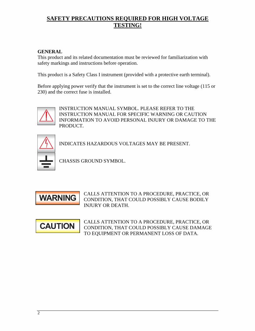
INSTRUCTION MANUAL SYMBOL. PLEASE REFER TO THE
INSTRUCTION MANUAL FOR SPECIFIC WARNING OR CAUTION
INFORMATION TO AVOID PERSONAL INJURY OR DAMAGE TO THE
PRODUCT.
INDICATES HAZARDOUS VOLTAGES MAY BE PRESENT.
CHASSIS GROUND SYMBOL.
CALLS ATTENTION TO A PROCEDURE, PRACTICE, OR
CONDITION, THAT COULD POSSIBLY CAUSE BODILY
INJURY OR DEATH.
CALLS ATTENTION TO A PROCEDURE, PRACTICE, OR
CONDITION, THAT COULD POSSIBLY CAUSE DAMAGE
TO EQUIPMENT OR PERMANENT LOSS OF DATA.

3
A Hipot produces voltages and currents which can cause harmful or fatal electric
shock. To prevent accidental injury or death, these safety procedures must be strictly
observed when handling and using the test instrument.
SERVICE AND MAINTENANCE
User Service
To prevent electric shock do not remove the instrument cover. There are no user
serviceable parts inside. Routine maintenance or cleaning of internal parts is not
necessary. Any external cleaning should be done with a clean dry or slightly damp cloth.
Avoid the use of cleaning agents or chemicals to prevent any foreign liquid from entering
the cabinet through ventilation holes or damaging controls and switches, also some
chemicals may damage plastic parts or lettering. Schematics, when provided, are for
reference only. Any replacement cables and high voltage components should be acquired
directly from Slaughter Company, Inc. Refer servicing to a Slaughter Company, Inc.
authorized service center.
SLAUGHTER COMPANY, INC.
28105 N. KEITH DRIVE
LAKE FOREST, IL 60045-4546 U.S.A.
PHONE: 1 (847) 932-3662
1 (800) 504-0055 FAX: 1 (847) 932-3665
E-MAIL : [email protected]
www.hipot.com
Service Interval
The instrument and its power cord, test leads, and accessories must be returned at least
once a year to a Slaughter Company authorized service center for calibration and
inspection of safety related components. Slaughter Company will not be held liable for
injuries suffered if the instrument is not returned for its annual safety check and
maintained properly.
User Modifications
Unauthorized user modifications will void your warranty. Slaughter Company will not
be responsible for any injuries sustained due to unauthorized equipment modifications or
use of parts not specified by Slaughter Company. Instruments returned to Slaughter
Company with unsafe modifications will be returned to their original operating condition
at your expense.
TEST STATION
Location
Select an area away from the main stream of activity which employees do not walk
through in performing their normal duties. If this is not practical because of production
line flow, then the area should be roped off and marked for HIGH VOLTAGE
TESTING. No employees other than the test operators should be allowed inside.

4
If benches are placed back-to-back, be especially careful about the use of the bench
opposite the test station. Signs should be posted: "DANGER - HIGH VOLTAGE
TEST IN PROGRESS - UNAUTHORIZED PERSONNEL KEEP AWAY."
Power
Dielectric Voltage-Withstand Test Equipment must be connected to a good ground. Be
certain that the power wiring to the test bench is properly polarized and that the proper
low resistance bonding to ground is in place.
Power to the test station should be arranged so that it can be shut off by one prominently
marked switch located at the entrance to the test area. In the event of an emergency,
anyone can cut off the power before entering the test area to offer assistance.
The mains plug is used as the disconnecting device and shall
remain readily operable. The socket-outlet shall be installed near
the equipment and shall be easily accessible.
Do not replace the power supply cord with an improperly rated
cord. For North American: A UL listed and CSA labeled power
cord must be used with the instrument in the United States and
Canada. The power cord must include a NEMA5-15 style male plug, SVT or SJT cord
sets, and be rated for at least 125VAC, 10A, number 16 gauge (or 125VAC, 15A, number
14 gauge) wire or larger, and the length of the cord does not exceed 2 m must be used.
For European: A certified power supply cord not lighter than light PVC sheathed flexible
cord according to IEC 60227, designation H03 VV-F or H03 VVH2-F (for equipment
mass not exceeding 3 kg), or H05 VV-F or H05 VVH2-F2 (for equipment mass
exceeding 3 kg), and be rated for at least 3G 0.75 mm² (for rated current up to 10 A) or
3G 1.0mm² (for rated current over 10 A up to 16 A) wire or larger, and the length of the
cord does not exceed 2 m must be used.
Work Area
Perform the tests on a non-conducting table or workbench, if possible.
There should not be any metal in the work area between the operator and the location
where products being tested will be positioned.
Position the tester so the operator does not have to reach over the product under test to
activate or adjust the tester. If the product or component being tested is small, it may be
possible to construct guards or an enclosure, made of a non-conducting material such as
clear acrylic, such that the item being tested is within the guards or enclosure during the
test, and fit them with switches so that the tester will not operate unless the guards are in
place or the enclosure closed.
Keep the area clean and uncluttered. All test equipment and test leads not absolutely
necessary for the test should be removed from the test bench and put away. It should be
clear to both the operator and to any observers which product is being tested, and which
ones are waiting to be tested or have already been tested.
Do not perform Hipot tests in a combustible atmosphere or in any area where
combustible materials are present.
5
TEST OPERATOR
Qualifications
This instrument generates voltages and currents which can cause harmful or fatal
electric shock and must only be operated by a skilled worker trained in its use.
The operator should understand the electrical fundamentals of voltage, current, and
resistance.
Safety Procedures
Operators should be thoroughly trained to follow these and all other applicable safety
rules and procedures before they begin a test. Defeating any safety system should be
treated as a serious offense and should result in severe penalties, such as removal from
the Hipot testing job. Allowing unauthorized personnel in the area during a test should
also be dealt with as a serious offense.
Dress
Operators should not wear jewelry which could accidentally complete a circuit.
Medical Restrictions
This instrument should not be operated by personnel with heart ailments or devices such
as pacemakers.
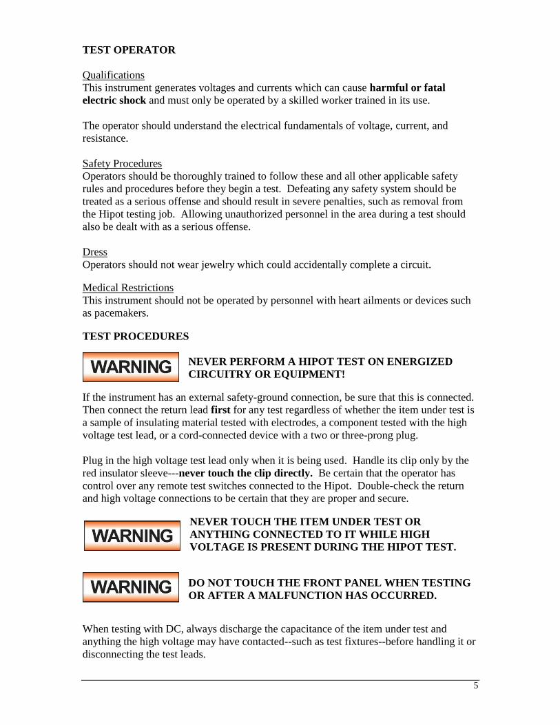
TEST PROCEDURES
NEVER PERFORM A HIPOT TEST ON ENERGIZED
CIRCUITRY OR EQUIPMENT!
If the instrument has an external safety-ground connection, be sure that this is connected.
Then connect the return lead first for any test regardless of whether the item under test is
a sample of insulating material tested with electrodes, a component tested with the high
voltage test lead, or a cord-connected device with a two or three-prong plug.
Plug in the high voltage test lead only when it is being used. Handle its clip only by the
red insulator sleeve---never touch the clip directly. Be certain that the operator has
control over any remote test switches connected to the Hipot. Double-check the return
and high voltage connections to be certain that they are proper and secure.
NEVER TOUCH THE ITEM UNDER TEST OR
ANYTHING CONNECTED TO IT WHILE HIGH
VOLTAGE IS PRESENT DURING THE HIPOT TEST.
DO NOT TOUCH THE FRONT PANEL WHEN TESTING
OR AFTER A MALFUNCTION HAS OCCURRED.
When testing with DC, always discharge the capacitance of the item under test and
anything the high voltage may have contacted--such as test fixtures--before handling it or
disconnecting the test leads.
6
HOT STICK probes can be used to discharge any capacitance in the item under test as a
further safety precaution. A hot stick is a non-conducting rod about two feet long with a
metal probe at the end which is connected to a wire. To discharge the device under test,
two hot sticks are required. First connect both probe wires to a good earth ground. Then
touch one probe tip to the same place the return lead was connected. While holding the
first probe in place, touch the second probe tip to the same place where the high voltage
lead was connected.
KEY SAFETY POINTS TO REMEMBER
Keep unqualified and unauthorized personnel away from the test area.
Arrange the test station in a safe and orderly manner.
Never touch the product or connections during a test.
In case of any problem, turn off the high voltage first.
Properly discharge any item tested with DC before touching connections.

7
GLOSSARY OF TERMS
(as used in this manual)
Alternating Current, AC: Current which reverses direction on a regular basis, commonly in the
U.S.A. 60 times per second, in other countries 50 times per second.
Breakdown: The failure of insulation to effectively prevent the flow of current, sometimes evident by
arcing. If voltage is gradually raised, breakdown will begin suddenly at a certain voltage level. Current
flow is not directly proportional to voltage. Once breakdown current has flown, especially for a period of
time, a repeated application of voltage will often show breakdown beginning at a lower voltage than
initially.
Conductor: A solid or liquid material which has the ability to let current pass through it, and which has
a volume resistivity of no more than 103 ohm-cm.
Current: The movement of electrons through a conductor. Current is measured in amperes,
milliamperes, microamperes, nanoamperes, or picoamperes. Symbol = I
Dielectric: An insulating material which is positioned between two conductive materials in such a way
that a charge or voltage may appear across the two conductive materials.
Direct Current, DC: Current which flows in one direction only. The source of direct current is said
to be polarized and has one terminal which is always at a higher potential than the other.
Insulation: Gas, liquid or solid material which has a volume resistivity of at least 1012 ohm-cm and is
used for the purpose of resisting current flow between conductors.
Leakage: AC or DC current flow through insulation and over its surfaces, and AC current flow through
a capacitance. Current flow is directly proportional to voltage. The insulation and/or capacitance is
thought of as a constant impedance, unless breakdown occurs.
Measuring Device (MD): A resistive and capacitive network used to simulate the impedance of the
human body during Line Leakage testing.
Resistance: That property of a substance which impedes current and results in the dissipation of power
in the form of heat. The practical unit of resistance is the ohm. Symbol = R
Trip Point: The minimum current flow required to cause an indication of unacceptable performance
during a dielectric voltage-withstand test.
Voltage: Electrical pressure, the force which causes current through an electrical conductor.
Symbol = V

8
INTRODUCTION
The importance of testing.... User safety
In an era of soaring liability costs, original manufacturers of electrical and electronic
products must make sure every item is as safe as possible. All products must be designed
and built to prevent electric shock, even when users abuse the equipment or bypass built-
in safety features.
To meet recognized safety standards, one common test is the "dielectric voltage-
withstand test". Safety agencies which require compliance safety testing at both the
initial product design stage and for routine production line testing include: Underwriters
Laboratories, Inc. (UL), the Canadian Standards Association (CSA), the International
Electrotechnical Commission (IEC), the British Standards Institution (BSI), the
Association of German Electrical Engineers (VDE), the Japanese Standards Association
(JSI). These same agencies may also require that an insulation resistance test and high
current ground bond test be performed.
The Dielectric Withstand (Hipot) Test....
The principle behind a dielectric voltage-withstand test is simple: if a product will
function when exposed to extremely adverse conditions, it can be assumed that the
product will function in normal operating circumstances.
The most common applications of the dielectric-withstand test are:
Design (performance) Testing.... determining design adequacy to meet service
conditions.
Production Line Testing.... detecting defects in material or workmanship during
processing.
Acceptance Testing.... proving minimum insulation requirements of purchased parts.
Repair Service Testing.... determine reliability and safety of equipment repairs.
During a dielectric voltage-withstand test, an electrical devise is exposed to a voltage
significantly higher than it normally encounters. The high voltage is continued for a
given period of time.
If stray current flow remains within specified limits during the time the component is
tested, the device is assumed to be safe under normal conditions.
The equipment used for this test, a dielectric-withstand tester, is often called a "Hipot"
(for high potential tester). The "rule of thumb" for testing is to subject the product to
twice its normal operating voltage, plus 1,000 volts. However, specific products may be
tested at much higher voltages than 2X operating voltages + 1,000 volts.
For example, a product designed to operate in the range between 100 to 240 volts can be
tested between 1,000 to 4,000 volts, or higher. Most "double insulated" products are
tested at voltages much higher than the "rule of thumb."
9
Testing during development and prototype stages is more stringent than production line
testing because the basic design of the product is evaluated. Design tests are usually
performed on only a few samples of the product. Production line tests are performed on
every item as it comes off the production line.
The Hipot tester must also maintain an output voltage between 100% and 120% of
specification. The output voltage of the Hipot must have a sinusoidal waveform with a
frequency between 40 to 70 Hz and has a peak waveform value that is not less than 1.3
and not more than 1.5 times the root-mean-square value.
Advantages and Disadvantages of AC Testing and DC Testing.... Please check with the Compliance Agency you are working with to see which of the two
types of voltages you are authorized to use. In some cases, a Compliance Agency will
allow either AC or DC testing. However, in other cases the Compliance Agency only
allows for an AC test. If you are unsure which specification you must comply with,
please contact our SALES DEPARTMENT at 1-800-504-0055.
AC testing characteristics
Most items that are Hipot tested have some amount of distributed capacitance. An AC
voltage cannot charge this capacitance so it continually reads the reactive current that
flows when an AC voltage is applied to a capacitive load.
AC testing advantages
1. AC testing is generally more accepted by safety agencies than DC testing. The
main reason for this is that most items being Hipot tested will operate at AC
voltages. AC Hipot testing offers the advantage of stressing the insulation
alternately in both polarities, which more closely simulates stresses the product will
normally see.
2. Since AC testing cannot charge a capacitive load the current reading remains
consistent from the initial application of the voltage, to the end of the test. There is
no need to gradually bring up the voltage since no stabilization is required to
monitor the current reading. Unless the product is sensitive to a sudden application
of voltage, the operator can immediately apply full voltage and read current without
any wait time.
3. Since AC voltage cannot charge a load there is no need to discharge the item under
test after the test.
AC testing disadvantages
1. Again, since AC cannot charge the item under test, reactive current is constantly
flowing. In many cases, the reactive component of the current can be much greater
than the real component due to actual leakage. This can make it very difficult to
detect products that have excessively high leakage current.
10
2. The Hipot has supply reactive and leakage current continuously. This may require a
current output that is actually much higher than is really required to monitor leakage
current, and in most cases is usually much higher than would be needed with a DC
tester. This can present increased safety risks as operators are exposed to higher
currents.
DC testing characteristics
During DC Hipot testing the item under test is charged. The capacitance that causes
reactive current in AC testing will now result in charging current, which exponentially
drops to zero during DC testing.
DC testing advantages
1. Once the item under test is fully charged the only current flowing is the true leakage
current. The DC Hipot tester clearly displays only the true leakage of the product
under test.
2. Since the charging current only needs to be applied momentarily, the output power
requirements of the DC Hipot tester can typically be much less than what would be
required in an AC tester.
DC testing disadvantages
1. Unless the item being tested has virtually no capacitance, it is necessary to raise the
voltage gradually from zero to the full test voltage. The more capacitive the item
the more slowly the voltage must be raised. This is important since most DC Hipots
have failure shut-off circuitry, which will indicate a failure almost immediately if
the total current reaches the leakage threshold during the initial charging of the
product under test.
2. Since a DC Hipot does charge the item under test, it becomes necessary to discharge
the item after the test.
3. A DC Hipot test only charges the insulation in one polarity. This becomes a
concern when testing products that will be used with AC voltages. As such, some
safety agencies do not accept DC testing as an alternative to AC testing.
4. When performing AC Hipot tests, the product under test is actually tested with peak
voltages that the Hipot meter does not display. This is not the case with DC testing
since a sine wave is not generated when testing with a DC voltage. In order to
compensate for this fact, most safety agencies require that the equivalent DC test be
performed at a higher voltage than the AC test. The multiplying factor is somewhat
inconsistent between agencies, which can cause confusion.
The Insulation Resistance Test....
Some dielectric analyzers today come with a built-in insulation resistance tester.
Typically, the IR function provides test voltages from 500 to 1,000 volts DC and
measures resistance from kilohms to gigohms. BABT, TÜV, and VDE are agencies that
may, under certain conditions, require an IR test on the product before a Hipot test is

11
performed. IR testing typically is not done on the production line, but as a performance
design test.
The IR test is very similar to the Hipot test. Instead of the go/no go indication that you
get with a Hipot test, the IR test indicates an insulation value, usually in Megohms.
Typically the higher the IR value, the better the condition of the insulation. The
measured value represents the equivalent resistance of all the insulation between the two
test points, and any component resistance which might also be connected between the
two points. The connections to perform the IR test are the same as the Hipot test.
Although the IR test can predict insulation condition, it does not replace the need to
perform a Dielectric Withstand test.
TYPES OF FAILURES DETECTABLE ONLY WITH A HIPOT TEST
Weak Insulating Materials
Pinholes in Insulation
Inadequate Spacing of Components
Pinched Insulation
Why Perform a Ground Bond Test….
Ground Bond testing is done to ensure that a low resistance path exists between the safety
ground pin of a three-wire line cord and exposed metal of the device under test. Ideally,
if a live wire inside the item under test became loose and contacted the chassis, the fault
current would flow through the low resistance safety ground, and protect the user.
The need for high current bonding (i.e. 30A or 60A) as apposed to low current go-no go
type testers, is the result of the line voltage breakers’ high current characteristics. Safety
grounding circuits must withstand the line voltage breaker’s current rating in order to
maintain safe voltage potentials on the chassis of the faulty device. Verifying the
integrity of the grounding circuit at high currents ensures that the line breaker will open
before the grounding circuit wires fail.
The Line Leakage Test….
The Line Leakage test measures the amount of leakage current that is produced while a
product is running. The test is unique in that it is performed while the DUT is running,
thus an external power supply is required to perform the test properly. Usually the user
needs to supply the voltage source to power the DUT.
Line Leakage tests use impedance models called measuring devices (MD’s) to measure
how much leakage current is being produced by a DUT under several conditions: normal,
reversed input polarity, open neutral, and open ground. Performing a Line Leakage test
gives manufacturers the opportunity to know how much leakage current a user will be
subjected to under a variety of different circumstances.
Line Leakage testing is commonly performed as a design/type test during new product
development. Configuration “G-L” represents an earth leakage test which measures the
leakage current from the DUT’s protective earth ground back to the system neutral.

12
Why Perform a Functional Run Test….
Functional Run testing, although not considered to be an electrical safety test, is
worthwhile to perform for a variety of reasons. The Functional Run test is primarily used
to determine if a DUT runs properly after it has been subjected to a battery of electrical
safety tests. Usually the test monitors various parameters including: input voltage, input
current, input power, and input power factor. Test operators can use the information
gained from the Functional Run test to determine if a DUT is operating properly before
the unit is shipped to a customer. This is beneficial since there is no electrical safety test
that can conclude if a product will power up and operate properly.
IF YOU SHOULD HAVE ANY QUESTIONS RELATING TO THE OPERATION
OF YOUR INSTRUMENT CALL 1 (800) 504-0055 IN THE U.S.A.
13
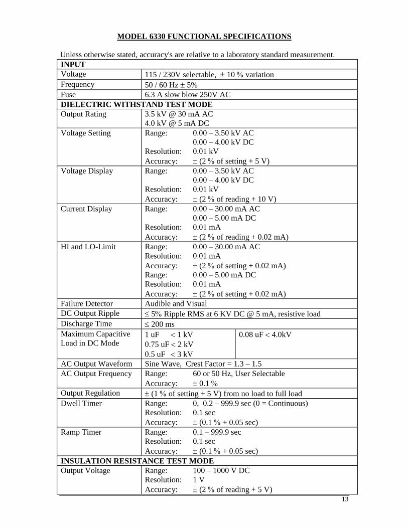
MODEL 6330 FUNCTIONAL SPECIFICATIONS
Unless otherwise stated, accuracy's are relative to a laboratory standard measurement.
INPUT
Voltage 115 / 230V selectable, 10 variation
Frequency 50 / 60 Hz 5%
Fuse 6.3 A slow blow 250V AC
DIELECTRIC WITHSTAND TEST MODE
Output Rating 3.5 kV @ 30 mA AC
4.0 kV @ 5 mA DC
Voltage Setting Range: 0.00 – 3.50 kV AC
0.00 – 4.00 kV DC
Resolution: 0.01 kV
Accuracy: (2 of setting + 5 V)
Voltage Display Range: 0.00 – 3.50 kV AC
0.00 – 4.00 kV DC
Resolution: 0.01 kV
Accuracy: (2 of reading + 10 V)
Current Display Range: 0.00 – 30.00 mA AC
0.00 – 5.00 mA DC
Resolution: 0.01 mA
Accuracy: (2 of reading + 0.02 mA)
HI and LO-Limit Range: 0.00 – 30.00 mA AC
Resolution: 0.01 mA
Accuracy: (2 of setting + 0.02 mA)
Range: 0.00 – 5.00 mA DC
Resolution: 0.01 mA
Accuracy: (2 of setting + 0.02 mA)
Failure Detector Audible and Visual
DC Output Ripple 5 Ripple RMS at 6 KV DC @ 5 mA, resistive load
Discharge Time 200 ms
Maximum Capacitive
Load in DC Mode 1 uF 1 kV
0.75 uF 2 kV
0.5 uF 3 kV
0.08 uF 4.0kV
AC Output Waveform Sine Wave, Crest Factor = 1.3 – 1.5
AC Output Frequency Range: 60 or 50 Hz, User Selectable
Accuracy: 0.1
Output Regulation (1 of setting + 5 V) from no load to full load
Dwell Timer Range: 0, 0.2 – 999.9 sec (0 = Continuous)
Resolution: 0.1 sec
Accuracy: (0.1 + 0.05 sec)
Ramp Timer Range: 0.1 – 999.9 sec
Resolution: 0.1 sec
Accuracy: (0.1 + 0.05 sec)
INSULATION RESISTANCE TEST MODE
Output Voltage Range: 100 – 1000 V DC
Resolution: 1 V
Accuracy: (2 of reading + 5 V)
14
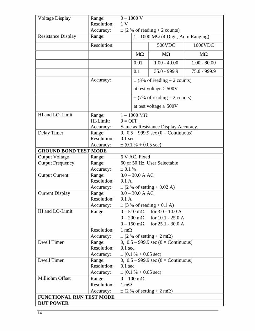
Voltage Display Range: 0 – 1000 V
Resolution: 1 V
Accuracy: (2 of reading + 2 counts)
Resistance Display Range: 1 - 1000 M (4 Digit, Auto Ranging)
Resolution: 500VDC 1000VDC
M M M
0.01 1.00 - 40.00 1.00 - 80.00
0.1 35.0 - 999.9 75.0 - 999.9
Accuracy: (3 of reading 2 counts)
at test voltage > 500V
(7 of reading 2 counts)
at test voltage 500V
HI and LO-Limit Range: 1 – 1000 M
HI-Limit: 0 = OFF
Accuracy: Same as Resistance Display Accuracy.
Delay Timer Range: 0, 0.5 – 999.9 sec (0 = Continuous)
Resolution: 0.1 sec
Accuracy: (0.1 + 0.05 sec)
GROUND BOND TEST MODE
Output Voltage Range: 6 V AC, Fixed
Output Frequency Range: 60 or 50 Hz, User Selectable
Accuracy: 0.1
Output Current Range: 3.0 – 30.0 A AC
Resolution: 0.1 A
Accuracy: (2 of setting + 0.02 A)
Current Display Range: 0.0 – 30.0 A AC
Resolution: 0.1 A
Accuracy: (3 of reading + 0.1 A)
HI and LO-Limit Range: 0 – 510 m for 3.0 - 10.0 A
0 – 200 m for 10.1 - 25.0 A
0 – 150 m for 25.1 - 30.0 A
Resolution: 1 m
Accuracy: (2 of setting + 2 m
Dwell Timer Range: 0, 0.5 – 999.9 sec (0 = Continuous)
Resolution: 0.1 sec
Accuracy: (0.1 + 0.05 sec)
Dwell Timer Range: 0, 0.5 – 999.9 sec (0 = Continuous)
Resolution: 0.1 sec
Accuracy: (0.1 + 0.05 sec)
Milliohm Offset Range: 0 – 100 m
Resolution: 1 m
Accuracy: (2 of setting + 2 m
FUNCTIONAL RUN TEST MODE
DUT POWER

15
AC Voltage 0 - 277.0 V, Single phase unbalanced, 0 - 30.0 A maximum
Current 30 A maximum continuous
Power Rating 8400 W maximum
DUT Protection Short Circuit current 50 A < 3 s, Inrush Current 180 A Response
time 10 us.
SETTINGS
Range Resolution Accuracy
HI and LO Limit AC
Voltage, V 0.0 - 277.0 0.1
± (1.5% of setting + 0.2
V), 60.0-277 V
HI and LO Limit AC
Current, A 0.0 - 30.0 0.1
± (2% of setting + 2
counts)
HI and LO Limit AC Power,
W 0 - 8400 1
± (5% of setting + 6
counts)
HI and LO Limit Power
Factor 0.000 - 1.000 0.001
W/VA, calculated and
displayed to three
significant digits
HI and LO Limit Leakage
Current
0.00 - 10.00, Hi-
Limit 0=OFF 0.01
± (2% of setting + 2
counts)
Delay Time, second 0.2 - 999.9
0.1 ± (0.1% + 0.05 sec) Dwell Time, second
0, 0.1 - 999.9
(0=continuous)
MEASUREMENT
Range Resolution Accuracy
Voltage, Vac 0.0 - 277.0 0.1 ± (1.5% of reading + 2
counts), 60.0~277 V
Current, Aac 0.0 - 30.0 0.1 ± (2% of reading + 2
counts)
Power, Watts 0 - 8400 1 ± (5% of reading + 6
counts)
Power, Factor 0.000 - 1.000 0.001
W/VA, calculated and
displayed to three
significant digits
Leakage Current, mA 0.00 - 10.00 0.01 ± (2% of reading + 2
counts)
MD Circuit Leakage Current measuring resistance = 2K Ω±1%
Timer, second 0.0 - 999.9 0.1 ± (0.1% of reading +
0.05 sec)
LINE LEAKAGE
DUT
DUT Input Power
Rating 0 - 277.0 V, Single phase unbalanced, 30 A maximum
Current 30 A maximum continuous
DUT Protection Short Circuit current 50 A < 3 s , Inrush Current 180 A Response
time 10 us.
SETTINGS
HI and LO Limit, uA Range 0-6000 uA, Resolution 1 uA, Hi-Limit 0=OFF
Delay Time, second Range 0, 1.0-999.9 (0=continuous), Resolution 0.1 s.
Compliance Standards A UL544NP, UL484, UL923, UL471, UL867, UL697

16
B IEC60990 Fig4 U2, IEC 60950-1, IEC60335-1,
IEC60598-1, IEC60065, IEC61010
C UL2601-1, IEC60601-1
X External MD(1K Ohm)
F Frequency check, External MD(1K Ohm)
Line Condition NEUTRAL, REVERSE, GROUND
Probe G - L
CURRENT MEASURMENT
Frequency Range DC to 1MHz
Leakage Current Range (RMS) 0uA - 6000uA
Resolution 1uA
Accuracy DC, 15KHz to 100KHz ±(2% of reading + 3µA)
>100KHz to 1MHz ±5% of reading(100uA-6000uA)
LINE VOLTAGE MEASUREMENT
Range 0.0-277.0 VAC
Resolution 0.1 V
Accuracy ± (1.5% of reading +0.2 V), 60.0-277.0 V
External MD Basic measuring element 1K Ω
MD A - C,X components Accuracy: Resistance ± 1% Capacitance ± 5%
MD Voltage Limit Maximum 30 V peak or 30 VDC
GENERAL SPECIFICATIONS
Safety Agency Listing CE, cTUVus, RoHS2
PLC Remote Control Input: Test, Reset, Interlock, Recall Memory 1 - 6
Output: Pass, Fail, Test-in-Process
Memory 20 memories, 10 steps per memory
All steps are linkable
Single step mode
Security Key Lock capability to avoid unauthorized access to all test
parameters. Memory Lock capability to avoid unauthorized
access to memory locations.
Line Cord Detachable 6 ft (1.8 m) power cable terminated in a three-prong
grounding plug.
Mechanical Tilt up front feet.
430 mm(W)×133 mm(H)×500 mm(D)/ 22Kg
Environmental Operating Temperature : 32 - 104F (0 - 40C)
Relative Humidity: 0 to 80%
Calibration Traceable to National Institute of Standards and Technology
(NIST). Calibration controlled by software. Adjustments are
made through front panel keypad in a restricted access
calibration mode. Calibration information stored in non-volatile
memory.
Why use the term “Counts”?
Slaughter publishes some specifications using COUNTS which allows us to provide a
better indication of the tester’s capabilities across measurement ranges. A COUNT refers
to the lowest resolution of the display for a given measurement range. For example, if the
resolution for voltage is 1V then 2 counts = 2V.

17
KEY FEATURES & BENEFITS OF MODEL 6330
1. Tamper proof front panel controls.
This makes it possible to limit user access to the setup screens so that only authorized
personnel can change test parameters.
2. Multiple Test Memories.
The 6330 provides twenty test memories with ten steps per memory. This is beneficial
for manufacturers testing multiple products on one production line.
3. Low-current sense.
The low current sense feature monitors the minimum level of current flow, thus
ensuring that the DUT is properly connected and that the Hipot test is being
performed.
4. Simple Menu Control.
All parameters for the setups can be adjusted through a simple menu driven program.
The easy to follow setup screens ensure that the operator correctly sets up all test
parameters.
5. Electronic dwell settings.
The electronic dwell control helps keep test results consistent by ensuring that the test
duration is the same for each product tested.
6. Electronic ramping.
Electronic ramping provides a gradual and timed method to increase output voltage to
the DUT, minimizing any damage from quickly over-applying high voltage to sensitive
DUTs.
7. Front panel LCD.
A front panel LCD allows the operator to monitor the test. The display holds the
results after a test item failure so that the operator can easily review the test results.
Failure indications are clearly displayed.
8. No load setup of trip current and output voltage.
This provides the operator with an easy and safe way to set trip currents and output
voltages since parameters are set without the high voltage present.
9. Storage of test program.
The 6330 powers up with the same parameters that were used during the last test to
avoid operator set up errors.
10. Output voltage fine adjustment.
To make the 6330 usable in all types of applications, the operator can manually bring
the voltage up or down in 10 volt increments by simply pressing the up and down
arrow keys. This makes it very easy to adjust the output voltage even while the
instrument is in the dwell mode so you can analyze test results at different voltages.
18
11. Software calibration control.
The 6330 is calibrated through the front panel keypad. All calibration information is
stored in non-volatile memory. This allows the instrument to be completely calibrated
without removing any covers and exposing the technician to hazardous voltages.
12. Current monitoring.
The LCD display allows monitoring of current down to 10 microamps AC and 10
microamps DC. This allows the 6330 to be used even when test requirements only
allow a very low level of acceptable leakage current.
13. Line and load regulation.
This system maintains the output voltage to within 1% from no load to full load and
over the line voltage range to ensure that test results remain consistent and within
safety agency requirements.
14. PLC remote inputs and outputs.
The standard 9- pin interfaces provide outputs for Pass, Fail, and Test in Process.
Inputs include Test, Reset, Interlock, and Memory Recall. This gives the user all the
basic remotes required to configure the instrument through simple PLC relay control.
15. Flashing high voltage indicator.
A flashing LED located directly over the high voltage terminal clearly indicates when
high voltage is active to provide maximum operator safety.
16. Single Step Test Mode.
In this mode, the 6330 can be configured to perform each test individually as a single
step. This provides the manufacturers flexibility in configuring their testing
procedure.
17. Insulation Resistance and Ground Bond Test Modes.
This allows the operator to perform an Insulation Resistance or Ground Bond tests
with the Dielectric Withstand (Hipot) test, thus eliminating the need for a separate
pieces of test equipment when IR and Ground Bond testing is required.
18. Continuous Duty Cycle Ratings.
An advantage over other instruments in its class, the 6330 does not have any
requirement to be shut down during the day even when used at full output.
19. Milliohm Offset Capability.
This feature minimizes the effect of test lead or test fixture resistance.
20. Adjustable Output Current and Milliohm Trip Currents.
The 6330 is versatile enough to meet a wide variety of safety agency specifications.
21. Key Lockout.
When enabled, Key Lockout disables all front panel keys except TEST and RESET.
22. Memory Lock

19
Memory Lock is a sub-function of Key Lockout. When enabled, the operator will only
have access to the TEST and RESET keys. When disabled, the operator will be able to
toggle between memory locations but not alter them.
23. Fail Stop ON/OFF Mode.
This allows the 6330 to be configured to continue testing after detecting a failure. All
pass/fail results are displayed at the completion of the test cycle.

20
FRONT PANEL CONTROLS
1. RESET BUTTON: This is a momentary contact switch used to reset the
instrument. If an out-of-range reading is detected during a test, the red failure lamp
within the button will light. To reset the system for the next test, press and release
this button. This button may also be used to abort a test in progress.
2. TEST BUTTON: This is a momentary contact switch used to start a test. Press the
green button to turn on the high voltage output when in test mode. The indicator
lamp within the button will light when test expires with pass condition.
3. LCD DISPLAY: The Liquid Crystal Display is the main readout for the operator
and programmer of the test settings and test results.
4. LOCK: This LED indicates that the Lock feature has been enabled.
5. BUS REMOTE INDICATOR: N/A
6. FAULT CONDITION INDICATORS: These LED’s indicate that the Neutral,
Reverse, and Ground Line Conditions have been activated during a Line Leakage
test.
7. CURRENT OUTPUT TERMINAL: This terminal is used for the connection of
the detachable 5-foot (1.52 m) red high current test lead. This terminal is always
used when performing a Ground Bond test.
8. POWER SWITCH: Rocker-style switch with international ON ( ) and OFF (0)
markings.
9. SET KEY: Use this key to advance forward through the setup menus.
10. DOWN ARROW (): Use this key to decrease the numeric values in the setup
mode. This key is also used to toggle ON/OFF functions. Also may be used to
decrease output voltage during a test in 10-volt increments.
8
1 2
9 1110 12
3
13 1514
4 5 6 7

21
11. UP ARROW (): Use this key to increase the numeric values in the setup mode.
This key is also used to toggle ON/OFF functions. Also may be used to increase
output voltage during a test in 10-volt increments.
12. EXIT KEY: Use this key when you desire to enter the test mode to initiate a test.
Also the key uses to enter the System menu parameters and to exit from the System
menu.
13. HIGH VOLTAGE OUTPUT TERMINAL: For the connection of the detachable
6-foot (1.8 m) red high voltage test lead. The silicone rubber insulation is flexible
for easy handling and is rated at 30KVDC. The terminal is recessed for safety when
this lead is not being used.
14. HIGH VOLTAGE ARROW (LED INDICATOR): This indicator flashes to warn
the operator that high voltage is present at the high voltage output terminal.
15. RETURN OUTPUT TERMINAL: For the connection of the detachable 5 foot
(1.52 m) black return test lead. This terminal is always used when performing a test.

22
REAR PANEL CONTROLS
1. EXTERNAL MD: Provides an access port for a custom measuring device. The port
may be activated during Line Leakage testing from the instrument’s menu system.
The operator must supply the appropriate measuring device as none is provided.
2. POWER CONTROL: N/A
3. FUSE RECEPTACLE: To change the fuse unplug the power (mains) cord and turn
the fuse cap counter clockwise to remove the fuse.
4. CALIBRATION ENABLE KEY: To enter the calibration mode press this key
while the instrument is being powered ON.
5. SIGNAL INPUT: 9 pin D subminiature male connector for remote control of TEST,
RESET, AND INTERLOCK functions as well as remote memory tests selection.
6. SIGNAL OUTPUT: 9 pin D subminiature female connector for monitoring PASS,
FAIL, and PROCESSING output relay signals.
7. DUT POWER INPUT: Provides the line and neutral connections for an input
power source to be used during Functional Run and Line Leakage testing. This input
requires connection to a U.S. style single phase unbalanced power supply.
8. DUT POWER OUTPUT: Provides the line and neutral connections from the 6330
to the DUT during Functional Run and Line Leakage testing. Provides the high
voltage connections to the DUT during ACW, DCW and IR testing if the DUT
OUTPUT and DUT-HV parameters are turned ON. Please refer to the Adapter Box
Connection section for details on connecting the adapter box between the instrument
and the device under test.
9. GND CONNECTION: This terminal is wired in parallel with the Current Output
terminal during a Ground Bond test and may be used in place of the front panel
7 8
1
1311109 12 14
2 3 4 5 6

23
connection. During a Line Leakage test this connection provides a connection to one
side of the measuring device (MD). Please refer to the Instrument Connections
section for details on connecting the instrument and the device under test.
10. CASE CONNECTION: This terminal is wired in parallel with the Return terminal
during a Ground Bond test and may be used in place of the front panel connection.
During a Line Leakage test this connection provides a connection to one side of the
measuring device (MD). During ACW, DCW or IR testing this terminal provides
the return connection. Please refer to the Instrument Connections section for
details on connecting the instrument and the device under test.
11. CHASSIS GROUND (EARTH) TERMINAL: This safety terminal should be
connected to a good earth ground before operation.
12. INPUT POWER RECEPTACLE: Standard IEC 320 connector for connection to a
standard NEMA style line power (mains) cord.
13. VOLTAGE SELECT SWITCH: Line voltage selection is set by the position of
the switch. In the left position, it is set for 115-volt operation, in the right position it
is set for 230-volt operation.
14. THERMAL FAN: To cool the instrument.

24
INSTALLATION
Introduction This section contains information for the unpacking, inspection, preparation for use and
storage of your Slaughter Company, Inc., product.
Unpacking and Inspection
Your instrument was shipped in a custom foam insulated container that complies with
ASTM D4169-92a Assurance Level II Distribution Cycle 13 Performance Test Sequence.
If the shipping carton is damaged, inspect the contents for visible damage such as dents,
scratches, or broken meters. If the instrument is damaged, notify the carrier and the
Slaughter Company customer support department immediately. Please save the shipping
carton and packing material for the carrier’s inspection. Our customer support
department will assist you in the repair or replacement of your instrument. Please do not
return your product without first notifying us and receiving an RMA (return materials
authorization) number.
Safe Lifting and Carrying Instructions
Proper methods of lifting and carrying can help to protect against injury. Follow the
recommendations below to ensure that instruments are handled in a safe manner.
Determine if the instrument can be lifted by one individual or requires additional
support.
Make sure that your balance is centered and your feet are properly spaced,
shoulder width apart behind the instrument.
Bend at the knees and make sure your back is straight.
Grip the instrument with your fingers and palms and do not lift unless your back
is straight.
Lift up with your legs, not your back.
Keep the instrument close to your body while carrying.
Lower the instrument by bending your knees. Keep you back straight.
Contents of the Carton
Inside the carton should be the following:
Description SLA Part Number

25
6330 Compliance Tester 6330 Hipot, Continuity, Ground
Bond, IR, Run and Line Leakage
102-055-913 High Voltage Lead (6ft.)
125-013-001 Input Power Cable (6ft.)
99-10457-01 Cable Assembly High Current
Return Lead
99-10468-01 High Current Output Lead
99-10009-01 High Current Clip with 6 ft Lead
99-10008-01 Ground Return Clip with 6 ft Lead
99-10469-01 LLT DUT Input Cable LINE
99-10470-01 LLT DUT Input Cable NEUTRAL
99-10471-01 LLT DUT HV Output Cable LINE
99-10472-01 LLT DUT HV Output Cable
NEUTRAL
99-10040-01 Interlock
99-10467-01 Adaptor Box
99-10106-01 Fuse
99-10573-01 RS-232 Cable Assembly
*The Line Cord listed is American. Other combinations of the Line Cord are available
upon request.
Only accessories which meet the manufacturer’s specification
shall be used.
Preparation for Use
Power Requirements and Line Voltage Selection
This instrument requires a power source of either 115 volts AC ±
10%, 47-63 Hz single phase or 230 volts AC ±10%, 47-63 Hz
single phase. Please check the rear panel to be sure the proper
switch setting is selected for your line voltage requirements before turning your
instrument on. In addition, please be sure the correct fuse is selected and installed while
the instrument is in the off position.
Do not switch the line voltage selector switch located on the rear
panel while the instrument is on or operating. This may cause
internal damage and represents a safety risk to the operator.
NOTE
For operation at 115 Volts AC and 230 Volts AC use a 6.3 A slow blow fuse.

26
Power Cable
BEFORE CONNECTING POWER TO THIS
INSTRUMENT, THE PROTECTIVE GROUND (EARTH)
TERMINALS OF THIS INSTRUMENT MUST BE
CONNECTED TO THE PROTECTIVE CONDUCTOR OF THE LINE (MAINS)
POWER CORD. THE MAIN PLUG SHALL ONLY BE INSERTED IN A
SOCKET OUTLET (RECEPTACLE) PROVIDED WITH A PROTECTIVE
GROUND (EARTH) CONTACT. THIS PROTECTIVE GROUND (EARTH)
MUST NOT BE DEFEATED BY THE USE OF AN EXTENSION CORD (POWER
CABLE) WITHOUT A PROTECTIVE CONDUCTOR (GROUNDING).
This instrument is shipped with a three-wire power cable. When this cable is connected
to an appropriate AC power source, this cable connects the chassis to earth ground. The
type of power cable shipped with each instruments depends on the country of destination.
Operating Environment This equipment is intended for indoor use only. The equipment has been evaluated
according to Installation Category II and Pollution Degree 2 as specified in IEC 664.
This instrument may be operated within the following environmental conditions:
Temperature………….41° - 104° F (5° - 40° C)
Relative humidity …….0 - 80%
Altitude ………………6,560 feet (2,000 meters)
Do not block any ventilation openings to prevent over heating of
the equipment. Keep the ventilation slits uncovered during
operation. Failure to do so could cause the instrument to overheat
and may damage internal components.
If the instrument is used in a matter not specified by the manufacturer, the protection
provided by the instrument may be impaired.
STORAGE AND SHIPMENT
Environment
This instrument may be stored or shipped in environments with the following limits:
Temperature.................-40° - 167° F (-40° - 75°C)
Altitude............................ 50,000 feet (15,240 meters)
The instrument should also be protected against temperature extremes which may cause
condensation within the instrument.
Field Installation of Options
There are no field installable options on the model 6330.

27
QUICK START
This Quick Start Guide assumes the operator has some familiarity with Hipot testing and
desires to use the "default" settings on the instrument. The default settings shown will
remain in memory unless you choose to override them with your own test program. The
instrument default settings are as follows:
DEFAULTS
Input Voltage: 115 or 230 volts AC country specific
(rear panel switch selectable)
System parameters:
PLC Remote: OFF
Single Step: OFF
Fail Stop: ON
Lock: OFF
Memory Lock: ON
Alarm Volume: 5
DUT HV-SET: ON
Test Parameters:
Memory Position: 1
Step Position: 1
Test Mode: AC
Voltage: 1.24 kV
HI-Limit: 10.00 mA
LO-Limit: 0.00 mA
Ramp: 0.1 s
Dwell: 1.0 s
Freq.: 60 Hz
Connect: OFF
DUT OUTPUT: ON

28
a). Unpack this instrument from its special shipping container.
b). Locate a suitable testing area and be sure you have read all
safety instructions for the operation of the instrument and
suggestions on the test area set-up in the SAFETY section of this
manual. Locate a three prong grounded outlet. Be sure the outlet has been tested for
proper wiring before connecting the instrument to it.
c). Check to be sure the correct input line voltage has been selected
on the rear panel. Either 115 volts AC or 230 volts AC. Connect
the power input plug into its socket on the rear panel of the
instrument. Connect the male end of the plug to the outlet receptacle.
Please be sure that the safety ground on the power line cord is not defeated and
that you are connecting to a grounded power source.
d). Turn on the POWER switch located on the lower left hand side of the front panel.
Upon powering the instrument up a POWER ON SELF TEST (POST) will automatically
be performed. This test will check for the condition of the ram chips, pcb's and other
critical components. In addition, you will see the Slaughter Company name, Model
Number, and current software version briefly appear on the LCD readout and then clear
itself.
You should then see the default parameters on the LCD meter as follows:
These abbreviated parameters stand for the following:
1 - 1: Indicates the memory and step location of the current settings.
Set: This is the parameter settings review screen
1.0s: The dwell timer is set to a test duration of 1 second.
1.24kVAC: The test voltage is set to 1,240 volts AC.
10.00mA: The high leakage current trip point is set to 10 milliamps.
If you wish to not use any one of these parameters you must change your parameters.
Please refer to the Operation Instructions section in this manual for further details.
e). If the instrument defaults are acceptable then be sure to connect the appropriate test
leads to the device under test (DUT) or test fixture. Be sure to connect this safety ground
to a suitable known good ground before energizing this instrument and then connect the
return lead first (black) to the test fixture or item followed by the high voltage output lead.
f). Please check your connections to be sure they are making good contact and that the test
station or area is clear of debris and other personnel.
SLAUGHTER
6330 Ver: 1.00
ACW Set 1.0s
1-1 1.24kV 10.00mA
29
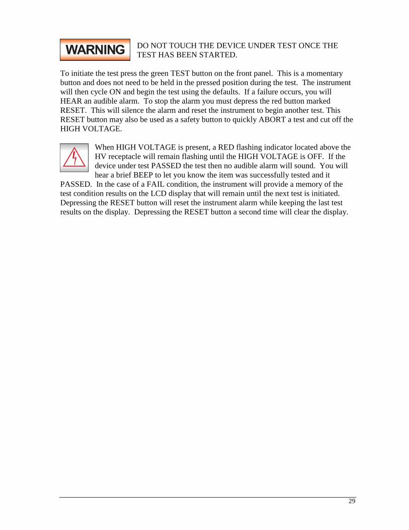
DO NOT TOUCH THE DEVICE UNDER TEST ONCE THE
TEST HAS BEEN STARTED.
To initiate the test press the green TEST button on the front panel. This is a momentary
button and does not need to be held in the pressed position during the test. The instrument
will then cycle ON and begin the test using the defaults. If a failure occurs, you will
HEAR an audible alarm. To stop the alarm you must depress the red button marked
RESET. This will silence the alarm and reset the instrument to begin another test. This
RESET button may also be used as a safety button to quickly ABORT a test and cut off the
HIGH VOLTAGE.
When HIGH VOLTAGE is present, a RED flashing indicator located above the
HV receptacle will remain flashing until the HIGH VOLTAGE is OFF. If the
device under test PASSED the test then no audible alarm will sound. You will
hear a brief BEEP to let you know the item was successfully tested and it
PASSED. In the case of a FAIL condition, the instrument will provide a memory of the
test condition results on the LCD display that will remain until the next test is initiated.
Depressing the RESET button will reset the instrument alarm while keeping the last test
results on the display. Depressing the RESET button a second time will clear the display.

30
OPERATION INSTRUCTIONS FOR MODEL 6330
POWER UP Check to be sure the correct input line voltage has been selected on the rear panel, either
115 volts AC or 230 volts AC. Connect the power input plug into its socket on the rear
panel of the instrument. Connect the male end of the plug to the outlet receptacle.
Be sure that the safety ground on the power line cord is not
defeated and that you are connecting to a grounded power source.
Connect the rear panel chassis ground for additional safety.
Turn on the POWER switch located on the lower left hand side of the front panel. Upon
powering the instrument up, a POWER ON SELF TEST (POST) will be automatically
performed. This test will check for the condition of the instrument’s critical components.
In addition the display will show the following message, with the actual model number
and software version number:
The instrument will recall the last memory program that was active and the display will
show the parameters that were programmed into that memory. The instrument is now
ready for operation.
SETUP PROCEDURE
1. Memory configuration
The model 6330 is equipped with 20 memory programs numbered 1 through 20. Each
memory location contains 10 separate steps that can be connected sequentially to the next
consecutive step. Only one test can be selected for each step.
Memory 1-10 Step 1-10
AC
DC
IR
GND
RUN
LLT
To recall a memory program press the SET key, then press the Up () or Down () arrow
keys until the specific memory you wish to recall is displayed. Please see procedures
below for details. Pressing the EXIT key will activate selected memory position. To start
a test, press the TEST button.
2. To select the Memory location
SLAUGHTER
6330 Ver: 1.00

31
Press the SET key once. The blinking underscore symbol appears directly under digit that
represents memory location. The blinking cursor indicates that the parameter is being
edited. The display shows:
or
or
Use the Up () or Down () arrow keys to select memory locations 1 through 10.
After selecting the memory, press the SET key to view the settings that have been
recalled from memory or to make any changes to these settings. Once you have entered
all the test data such as test function and parameters of that function, as outlined in the
below procedures, press the EXIT key to store any changes and return to the test mode.
3. To select the Step location
Press the SET key twice. The blinking underscore symbol appears directly under digit
that represents step location. The blinking cursor indicates that the parameter is being
edited. The display shows:
or
or
Use the Up () or Down () arrow keys to select step locations 1 through 20, then press
the EXIT key to store the current setting and return to the test mode, or press the SET key
to advance to the next parameter.
4. To set the test type
To change the Test type on the model 6330, please press the SET key three times until
the display shows:
ACW Memory
XXX.Xs
XX-XX X.XXkV XX.XXmA
or DCW Memory XXX.Xs
XX-XX X.XXkV XX.XXmA
IR Memory XXX.Xs
XX-XX XXXXV XXXXMΩ
or GND Memory XXX.Xs
XX-XX XXXmΩ XX.XXA
RUN Memory XXX.Xs
XX-XX XXXV XX.XXA
or LLT Memory XXX.Xs
XX-XX XXXV XX.XXA
ACW Step XXX.Xs
XX-XX X.XXkV XX.XXmA
or DCW Step XXX.Xs
XX-XX X.XXkV XX.XXmA
IR Step
XXX.Xs
XX-XX XXXXV XXXXMΩ
or GND Step XXX.Xs
XX-XX XXXmΩ XX.XXA
RUN Step XXX.Xs
XX-XX XXXV XX.XXA
or LLT Step XXX.Xs
XX-XX XXXV XX.XXA
Mode = AC or Mode = DC

32
or
or
Press the Up () or Down () arrow keys to toggle the test selection between AC, DC,
IR, GND, RUN, and LLT modes; then press the EXIT key to store the setting and return
to the selected test mode or press the SET key if the parameters of the selected test need
to be changed.
5. AC and DC dielectric withstand test modes setting (ACW/DCW)
5.1. To set the Output Voltage
Press the SET key until the display shows:
Use the Up () or Down () arrow keys to enter the desired test voltage, then press the
SET key to advance to the next parameter or press the EXIT key to store the setting and
return to the test mode. The maximum voltage which may be entered is 3.50kV AC or
4.00kV DC. Any attempt to set the value outside these limits will cause the instrument to
signal an ERROR by producing two short beeps. Pressing the Down () arrow key when
Voltage = 0.00kV also will cause the instrument to signal an ERROR by producing two
short beeps.
5.2. To set the High Leakage Current Limit
Press the SET key until the display shows:
Use the Up () or Down () arrow keys to enter the leakage current high limit setting,
then press the SET key to advance to the next parameter or press the EXIT key to store
the setting and return to the test mode. The unit of measure is in milliamperes with
20.00mA AC and 5.00mA DC as the maximum setting and with 0.00mA AC and DC as
minimum setting. The High Leakage Current Limit will act as the high “trip point” for
the Hipot test. If the measured leakage current exceeds the value, the test will fail. Any
attempt to set the value above this limit will cause the instrument to signal an ERROR by
producing two short beeps.
5.3. To set the Low Leakage Current Limit
Press the SET key until the display shows:
Mode = IR
or Mode = GND
Mode = RUN
or Mode = LLT
Voltage = X.XXkV
HI-Limit = XX.XXmA

33
Use the Up () or Down () arrow keys to enter the leakage current low limit setting,
then press the SET key to advance to the next parameter or press the EXIT key to store
the setting and return to the test mode. The unit of measure is milliamperes with
30.00mA AC and 5.00mA DC as the maximum setting and with 0.00mA AC and DC as
the minimum setting. The Low Leakage Current Limit will act as the low “trip point” for
the Hipot test. If the measured leakage current does not exceed this value, the test will
fail. Any attempt to set the value below this limit will cause the instrument to signal an
ERROR by producing two short beeps.
5.4. To set the Ramp time
Press the SET key until the display shows:
Use the Up () or Down () arrow keys to enter the ramp time setting, then press the
SET key to advance to the next parameter or press the EXIT key to store the setting and
return to the test mode. The minimum ramp time setting is 0.1 seconds, the maximum
ramp time setting is 999.9 seconds. Any attempt to set the values outside these limits will
cause the instrument to signal an ERROR by producing two short beeps.
5.5. To set the Dwell time
Press the SET key until the display shows:
Use the Up () or Down () arrow keys to enter the desired dwell time, then press the
SET key to advance to the next parameter or press the EXIT key to store the setting and
return to the test mode. If the dwell time is set to 0.0s, the instrument will operate in a
continuous ON mode when the TEST button is pressed. The instrument will stop when
the DUT (Device Under Test) goes into failure or the RESET button is pressed. The
actual minimum dwell time setting is 0.2 seconds. The maximum dwell time setting is
999.9 seconds. Any attempt to set the value more than 999.9s or less than 0.0s will cause
the instrument to indicate an ERROR by producing two short beeps.
5.6. To set the Frequency 50/60 Hz (For AC mode only)
Please press the SET key until the display shows:
Press the Up () or Down () arrow keys to toggle the frequency setting to 50 or 60
Hertz, then press the SET key to advance to the next parameter or press the EXIT key to
store the setting and return to the test mode.
5.7. To set the DUT OUTPUT ON
LO-Limit = XX.XXmA
Ramp = XXX.Xs
Dwell = XXX.Xs
Freq. = 60Hz
or Freq. = 50Hz

34
Press the SET key until the display shows:
DUT Output = OFF
or DUT Output = ON
Press the Up () or Down () arrow keys to toggle the DUT OUTPUT mode to ON or
OFF, then press the SET key to advance to the next parameter or press the EXIT key to
store the setting and return to the first parameter. If DUT OUTPUT is set to ON the
Output Power connections will become live during testing. These terminals may be used
to apply high voltage to the DUT from the rear panel. If DUT OUTPUT is set to OFF
voltage and current will only be present on the front panel connections.
5.8. To set the Connect mode ON/OFF
Press the SET key until the display shows:
Press the Up () or Down () arrow keys to toggle the connect mode to ON or OFF, then
press the SET key to advance to the next parameter or press the EXIT key to store the
setting and return to the first parameter. If Connect is set to ON the next step in the
sequence will be executed. If Connect is set to OFF the test sequence will stop at this
step. If step 10 is set to ON the test process will be connected to the first step of the next
memory. Step 10 of the memory 20 does not have Connect ON/OFF option.
6. IR insulation resistance test mode setting
6.1. To set the Output Voltage
Press the SET key until the display shows:
Use the Up () or Down () arrow keys to enter the desired test voltage, then press the
SET key to advance to the next parameter or press the EXIT key to store the setting and
return to the test mode. The maximum voltage which may be entered is 1000 Volts DC
and the minimum voltage is 100Volts DC. Any attempt to set the value above this limit
will cause the instrument to indicate an ERROR by producing two short beeps.
6.2. To set the High Resistance Limit
Press the SET key until the display shows:
Use the Up () or Down () arrow keys to enter the desired resistance high limit setting,
then press the SET key to advance to the next parameter or press the EXIT key to store
the setting and return to the test mode. The unit of measure is in Megohms with 0M -
1000M range of setting. Any attempt to set the value above this limit will cause the
instrument to indicate an ERROR by producing two short beeps. A measured value above
Connect = OFF
or Connect = ON
Voltage = XXXXV
HI-Limit = XXXXM
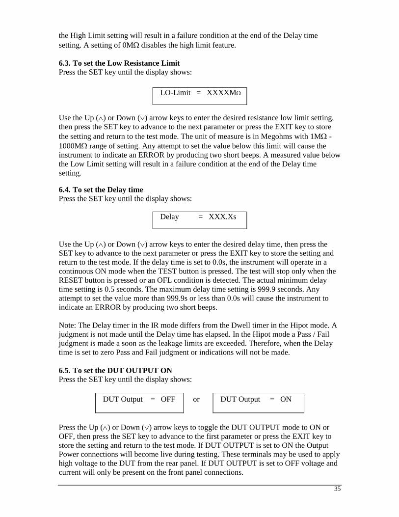
35
the High Limit setting will result in a failure condition at the end of the Delay time
setting. A setting of 0M disables the high limit feature.
6.3. To set the Low Resistance Limit
Press the SET key until the display shows:
Use the Up () or Down () arrow keys to enter the desired resistance low limit setting,
then press the SET key to advance to the next parameter or press the EXIT key to store
the setting and return to the test mode. The unit of measure is in Megohms with 1M -
1000M range of setting. Any attempt to set the value below this limit will cause the
instrument to indicate an ERROR by producing two short beeps. A measured value below
the Low Limit setting will result in a failure condition at the end of the Delay time
setting.
6.4. To set the Delay time
Press the SET key until the display shows:
Use the Up () or Down () arrow keys to enter the desired delay time, then press the
SET key to advance to the next parameter or press the EXIT key to store the setting and
return to the test mode. If the delay time is set to 0.0s, the instrument will operate in a
continuous ON mode when the TEST button is pressed. The test will stop only when the
RESET button is pressed or an OFL condition is detected. The actual minimum delay
time setting is 0.5 seconds. The maximum delay time setting is 999.9 seconds. Any
attempt to set the value more than 999.9s or less than 0.0s will cause the instrument to
indicate an ERROR by producing two short beeps.
Note: The Delay timer in the IR mode differs from the Dwell timer in the Hipot mode. A
judgment is not made until the Delay time has elapsed. In the Hipot mode a Pass / Fail
judgment is made a soon as the leakage limits are exceeded. Therefore, when the Delay
time is set to zero Pass and Fail judgment or indications will not be made.
6.5. To set the DUT OUTPUT ON
Press the SET key until the display shows:
DUT Output = OFF
or DUT Output = ON
Press the Up () or Down () arrow keys to toggle the DUT OUTPUT mode to ON or
OFF, then press the SET key to advance to the first parameter or press the EXIT key to
store the setting and return to the test mode. If DUT OUTPUT is set to ON the Output
Power connections will become live during testing. These terminals may be used to apply
high voltage to the DUT from the rear panel. If DUT OUTPUT is set to OFF voltage and
current will only be present on the front panel connections.
LO-Limit = XXXXM
Delay = XXX.Xs

36
6.6. To set the Connect mode ON/OFF
Press the SET key until the display shows:
Press the Up () or Down () arrow keys to toggle the connect mode to ON or OFF, then
press the SET key to advance to the next parameter or press the EXIT key to store the
setting and return to the test mode. If Connect is set to ON the next step in the sequence
will be executed. If Connect is set to OFF the test sequence will stop at this step. If step
10 is set to ON the test process will be connected to the first step of the next memory.
Step 10 of the memory 20 does not have Connect ON/OFF option.
7. GND Bond test mode setting
7.1. To set the Output Current
Press the SET key until the display shows:
Use the Up () or Down () arrow keys to enter the desired output current setting, then
press the SET key to advance to the next parameter or press the EXIT key to store the
current setting and return to the test mode. The unit of measure is in amperes with 3A –
30A range of setting. Any attempt to set the value outside these limits will cause the
instrument to indicate an ERROR message by producing two short beeps.
7.2. To set the High or Low Limits
Press the SET key until the display shows:
Use the Up () or Down () arrow keys to enter the desired value of the High or Low
Limits resistance trip point then press the SET key to advance to the next parameter or
press the EXIT key to store the setting and return to the test mode. The unit of measure is
in milliohms with a range of 0m - 510m at a current of 3.0A – 10.0A, 0m - 200m
at current of 10.1A – 25.0A, and 0m – 150mat current of 25.1A – 30.0A. Any
attempt to set the value outside this limits will cause the instrument to indicate an
ERROR message by producing two short beeps.
7.3. To set the Dwell time
Press the SET key until the display shows:
Use the Up () or Down () arrow keys to enter the desired dwell time, then press the
SET key to advance to the next parameter or press the EXIT key to store the setting and
return to the test mode. If the dwell time is set to 0.0s, the instrument will operate in a
Connect = OFF
or Connect = ON
Current = XX.XA
HI-Limit = XXXm
or LO-Limit = XXXm
Dwell = XXX.Xs
37
continuous ON mode when the TEST button is pressed. It will stop when the RESET
button is pressed or the DUT goes into failure. The actual minimum dwell time setting is
0.5 seconds. The maximum dwell time setting is 999.9 seconds. Any attempt to set the
value more than 999.9s or less than 0.0s will cause the instrument to indicate and
ERROR by producing two short beeps.
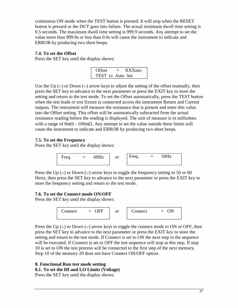
7.4. To set the Offset
Press the SET key until the display shows:
Use the Up () or Down () arrow keys to adjust the setting of the offset manually, then
press the SET key to advance to the next parameter or press the EXIT key to store the
setting and return to the test mode. To set the Offset automatically, press the TEST button
when the test leads or test fixture is connected across the instrument Return and Current
outputs. The instrument will measure the resistance that is present and enter this value
into the Offset setting. This offset will be automatically subtracted from the actual
resistance reading before the reading is displayed. The unit of measure is in milliohms
with a range of 0m - 100m. Any attempt to set the value outside these limits will
cause the instrument to indicate and ERROR by producing two short beeps.
7.5. To set the Frequency
Press the SET key until the display shows:
Press the Up () or Down () arrow keys to toggle the frequency setting to 50 or 60
Hertz, then press the SET key to advance to the next parameter or press the EXIT key to
store the frequency setting and return to the test mode.
7.6. To set the Connect mode ON/OFF
Press the SET key until the display shows:
Press the Up () or Down () arrow keys to toggle the connect mode to ON or OFF, then
press the SET key to advance to the next parameter or press the EXIT key to store the
setting and return to the test mode. If Connect is set to ON the next step in the sequence
will be executed. If Connect is set to OFF the test sequence will stop at this step. If step
10 is set to ON the test process will be connected to the first step of the next memory.
Step 10 of the memory 20 does not have Connect ON/OFF option.
8. Functional Run test mode setting
8.1. To set the HI and LO Limits (Voltage)
Press the SET key until the display shows:
Offset = XXXm
TEST to Auto Set
Freq. = 60Hz
or Freq. = 50Hz
Connect = OFF
or Connect = ON

38
Use the Up () or Down () arrow keys to enter the desired value of the High or Low
Limits voltage trip point then press the SET key to advance to the next parameter or press
the EXIT key to store the setting and return to the test mode. The unit of measure is 0 –
277 VAC. Any attempt to set the value outside these limits will cause the instrument to
indicate an ERROR by producing two short beeps.
8.2. To set the HI and LO Limits (Current)
Press the SET key until the display shows:
Use the Up () or Down () arrow keys to enter the desired value of the High or Low
Limits resistance trip point then press the SET key to advance to the next parameter or
press the EXIT key to store the setting and return to the test mode. The unit of measure is
0 – 30 amps. Any attempt to set the value outside these limits will cause the instrument to
indicate and ERROR by producing two short beeps.
8.3. To set the HI and LO Limits (Power)
Press the SET key until the display shows:
Use the Up () or Down () arrow keys to enter the desired value of the High or Low
Limits resistance trip point then press the SET key to advance to the next parameter or
press the EXIT key to store the setting and return to the test mode. The unit of measure is
0 – 8400 W. Any attempt to set the value outside these limits will cause the instrument to
indicate an ERROR by producing two short beeps.
8.4. To set the HI and LO Limits (Power Factor)
Press the SET key until the display shows:
Use the Up () or Down () arrow keys to enter the desired value of the High or Low
Limits resistance trip point then press the SET key to advance to the next parameter or
press the EXIT key to store the setting and return to the test mode. Power factor may be
set from 0 – 1. Power factor is indication of how resistive or reactive the DUT is. A
power factor of 1 corresponds to a purely resistive DUT whereas a power factor of 0
corresponds to a purely reactive DUT. Any attempt to set the value outside these limits
will cause the instrument to indicate an ERROR by producing two short beeps.
8.5. To set the HI and LO Limits (Leakage Current)
Press the SET key until the display shows:
Volt-HI = XXX V
or Volt-LO = XXX V
Amp-HI = XXX A
or Amp-LO = XXX A
Power-HI = XXX W
or Power-LO = XXX W
PF-HI = X.XXX
or PF-LO = X.XXX

39
Use the Up () or Down () arrow keys to enter the desired value of the High or Low
Limits resistance trip point then press the SET key to advance to the next parameter or
press the EXIT key to store the setting and return to the test mode. The unit of measure is
0 – 10.00 mA. Any attempt to set the value outside these limits will cause the instrument
to indicate an ERROR by producing two short beeps.
8.6. To set the Delay time
Press the SET key until the display shows:
Use the Up () or Down () arrow keys to enter the desired delay time, then press the
SET key to advance to the next parameter or press the EXIT key to store the setting and
return to the test mode. If the delay time is set to 0.0s, the instrument will operate in a
continuous ON mode when the TEST button is pressed. The test will stop only when the
RESET button is pressed or the OFL detected. The actual minimum delay time setting is
0.5 seconds. The maximum delay time setting is 999.9 seconds. Any attempt to set the
value more than 999.9s or less than 0.0s will cause the instrument to indicate an ERROR
by producing two short beeps.
Note: The Delay timer in the Functional Run test mode differs from the Dwell timer in
the Hipot mode. A judgment is not made until the Delay time has elapsed. Therefore,
when the Delay time is set to zero Pass and Fail judgment or indications will not be
made.
8.7. To set the Dwell time
Press the SET key until the display shows:
Use the Up () or Down () arrow keys to enter the desired dwell time, then press the
SET key to advance to the next parameter or press the EXIT key to store the setting and
return to the test mode. If the dwell time is set to 0.0s, the instrument will operate in a
continuous ON mode when the TEST button is pressed. It will stop when the RESET
button is pressed or the DUT goes into failure. The actual minimum dwell time setting is
0.5 seconds. The maximum dwell time setting is 999.9 seconds. Any attempt to set the
value more than 999.9s or less than 0.0s will cause the instrument to indicate an ERROR
by producing two short beeps.
8.8. To set the Connect mode ON/OFF
Press the SET key until the display shows:
Leakage-HI = XX.XXm
or Leakage-LO = XX.XXm
Delay = XXX.Xs
Dwell = XXX.Xs
Connect = OFF
or Connect = ON

40
Press the Up () or Down () arrow keys to toggle the connect mode to ON or OFF, then
press the SET key to advance to the next parameter or press the EXIT key to store the
setting and return to the test mode. If Connect is set to ON the next step in the sequence
will be executed. If Connect is set to OFF the test sequence will stop at this step. If step
10 is set to ON the test process will be connected to the first step of the next memory.
Step 10 of the memory 20 does not have Connect ON/OFF option.
9. Line Leakage test mode setting
9.1. To set the HI and LO Limits (Voltage)
Press the SET key until the display shows:
Please use the Up () or Down () arrow keys to enter the desired value of the High or
Low Limits voltage trip point then press the SET key to advance to the next parameter or
press the EXIT key to store the setting and return to the test mode. The unit of measure is
0 – 277 VAC. Any attempt to set the value outside these limits will cause the instrument
to indicate an ERROR by producing two short beeps.
9.2. To set the HI and LO Limits (Leakage Current)
Press the SET key until the display shows:
Please use the
Up () or Down () arrow keys to enter the desired value of the High or Low Limits
resistance trip point then press the SET key to advance to the next parameter or press the
EXIT key to store the setting and return to the test mode. The unit of measure is 0 – 10.00
mA. Any attempt to set the value outside these limits will cause the instrument to indicate
and ERROR by producing two short beeps.
9.3. To set the Line Condition
Press the SET key until the display shows:
Use the Up () or Down () arrow keys to select the desired Line Condition. The
available Line Conditions for the Line Leakage test are as follows:
Line 1 2 3 4 5 6 7 8
Neutral OPEN OPEN OPEN OPEN CLOSE CLOSE CLOSE CLOSE
Reverse OFF ON OFF ON OFF ON OFF ON
Ground OPEN OPEN CLOSE CLOSE OPEN OPEN CLOSE CLOSE
As the Line Condition is set, the corresponding LED’s on the front panel will illuminate.
These LED’s will signify which Line Condition is active for the test step. Press the SET
key to advance to the next parameter or press the EXIT key to store the setting and return
to the test mode.
Volt-HI = XXX V
or Volt-LO = XXX V
Leakage-HI = XXXXuA
or Leakage-LO =
XXXXuA
Line = 1

41
9.4. To set the Measuring Device (MD)
Press the SET key until display shows:
Use the Up () or Down () arrow keys to select the desired Measuring Device. The
available measuring devices are as follows:
Cross
Reference
Letter
Agency Specification Application
A UL544NP, UL484, UL923, UL471,
UL867, UL697
Non-Patient Medical Equipment
B IEC60990 Fig4 U2, IEC 60950-1,
IEC60335-1, IEC60598-1,
IEC60065, IEC61010
IT Equipment, Household
Appliances, Luminaries,
Laboratory Equipment
C UL2601-1, IEC60601-1 Medical Equipment
External User configurable User configurable
Frequency
Check
The Line Leakage test can be
configured to verify the bandwidth of
the leakage current “voltmeter.”
The selection is intended to be
used for meter verification only
and has no application for normal
testing.
Press the SET key to advance to the next parameter or press the EXIT key to store the
setting and return to the test mode.
Circuit Diagrams
The following diagrams show the equivalent circuit of the measuring devices. Leakage
current readings are generated by measuring the voltage drop across these networks and
dividing by the equivalent DC resistance. The voltmeter is placed across the entire
network of the measuring device A. The voltmeter is placed across the points indicated
by the solid black dots on measuring devices B and C. The points are specified by the
agencies that require a particular measuring device to meet their specification.
MD = A

42
9.5. To set the Delay time
Press the SET key until the display shows:
Use the Up () or Down () arrow keys to enter the desired delay time, then press the
SET key to advance to the next parameter or press the EXIT key to store the setting and
return to the test mode. If the delay time is set to 0.0s, the instrument will operate in a
continuous ON mode when the TEST button is pressed. The test will stop only when the
RESET button is pressed or the OFL detected. The actual minimum delay time setting is
0.5 seconds. The maximum delay time setting is 999.9 seconds. Any attempt to set the
Delay = XXX.Xs

43
value more than 999.9s or less than 0.0s will cause the instrument to indicate an ERROR
by producing two short beeps.
Note: The Delay timer in the Line Leakage mode differs from the Dwell timer in the
Hipot mode. A judgment is not made until the Delay time has elapsed. Therefore, when
the Delay time is set to zero Pass and Fail judgment or indications will not be made.
9.6. To set the Connect mode ON/OFF
Press the SET key until the display shows:
Press the Up () or Down () arrow keys to toggle the connect mode to ON or OFF, then
press the SET key to advance to the next parameter or press the EXIT key to store the
setting and return to the test mode. If Connect is set to ON the next step in the sequence
will be executed. If Connect is set to OFF the test sequence will stop at this step. If step
10 is set to ON the test process will be connected to the first step of the next memory.
Step 10 of the memory 20 does not have Connect ON/OFF option.
10. System Menu Parameters Setting
10.1. To set the PLC Remote ON/OFF
Press EXIT key once. The display shows:
Use the Up () or Down () arrow keys to change the PLC Remote setting, then press the
SET key to advance to the next parameter or press the EXIT key to store the setting and
return to the test mode. When the PLC Remote is turned ON the front panel TEST button
is disabled and a test may only be started through the rear panel I/O. If you attempt to
start a test from the front panel TEST button when the PLC Remote function is turned
ON the instrument will produce two short beeps and the following pop-up message will
be displayed:
Message will disappear after a few seconds or it can be cleared with the RESET button.
10.2. To set the Single Step ON/OFF
Press EXIT key once then press the SET key until the display shows:
Use the Up () or Down () arrow keys to change the Single Step setting, then press the
SET key to advance to the next parameter or press the EXIT key to store the setting and
return to the test mode.
Connect = OFF
or Connect = ON
PLC Remote = OFF
or PLC Remote = ON
PLC Remote ON
Single Step = OFF
or Single Step = ON

44
This function is used to temporarily override the automatic connection feature. When the
Single Step function is ON the instrument will pause after each step is completed, even
though the step Connect function is set to ON. To continue the test sequence, press the
TEST button. Each time the TEST button is pressed the next connected step will execute.
If you press the RESET button before completing all connected steps, it will return the
instrument to the original starting step. If a step fails and you wish to continue to the next
step, do not press the RESET button, press the TEST button.
10.3. To set the Fail Stop ON/OFF
Press EXIT key once then press the SET key until the display shows:
Use the Up () or Down () arrow keys to change the Fail Stop setting, then press the
SET key to advance to the next parameter or press the EXIT key to store the setting and
return to the test mode.
Fail Stop is a function that will stop a sequence of tests if a failure occurs. If this function
is turned OFF, the sequence of tests will continue to the end of the sequence regardless of
whether or not a failure has occurred. If the Fail Stop is ON and a failure occurs during
the test sequence, the red RESET button will light and a short alarm will sound but the
sequence will continue to the end. At the end of the test sequence, the red RESET button
will light and alarm will sound indicating failure during the sequence. Pressing the
RESET button will silence the alarm and reset the instrument.
10.4. Key Lock or Memory Lock setting
The model 6330 is equipped with two different levels of lockout selection. The first
selection is Key Lock. Within this selection, you can lockout all front panel control
functions except TEST and RESET. The second selection is Memory Lock and is used in
conjunction with the Key Lock. Within this selection, you can lockout all front panel
control functions except TEST, RESET and memory select.
Use the following chart to set the Key Lock and Memory Lock for your application.
To set the key Lock ON please press EXIT key once and then press the SET key until the
display shows:
Fail Stop = OFF
or Fail Stop = ON
Key Lock Memory Lock Accessible keys
OFF OFF All
OFF ON All
ON OFF TEST, RESET, and SET/Up-Down arrows
for memory selection
ON ON TEST and RESET
Lock = OFF
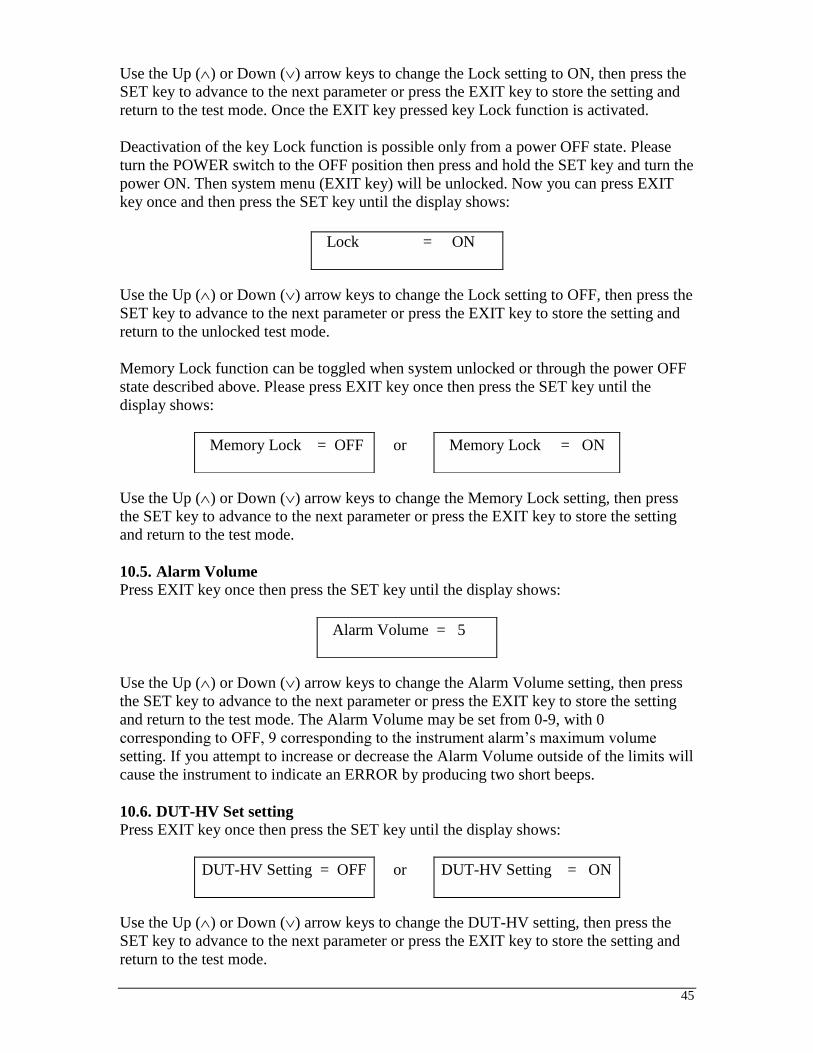
45
Use the Up () or Down () arrow keys to change the Lock setting to ON, then press the
SET key to advance to the next parameter or press the EXIT key to store the setting and
return to the test mode. Once the EXIT key pressed key Lock function is activated.
Deactivation of the key Lock function is possible only from a power OFF state. Please
turn the POWER switch to the OFF position then press and hold the SET key and turn the
power ON. Then system menu (EXIT key) will be unlocked. Now you can press EXIT
key once and then press the SET key until the display shows:
Use the Up () or Down () arrow keys to change the Lock setting to OFF, then press the
SET key to advance to the next parameter or press the EXIT key to store the setting and
return to the unlocked test mode.
Memory Lock function can be toggled when system unlocked or through the power OFF
state described above. Please press EXIT key once then press the SET key until the
display shows:
Use the Up () or Down () arrow keys to change the Memory Lock setting, then press
the SET key to advance to the next parameter or press the EXIT key to store the setting
and return to the test mode.
10.5. Alarm Volume
Press EXIT key once then press the SET key until the display shows:
Use the Up () or Down () arrow keys to change the Alarm Volume setting, then press
the SET key to advance to the next parameter or press the EXIT key to store the setting
and return to the test mode. The Alarm Volume may be set from 0-9, with 0
corresponding to OFF, 9 corresponding to the instrument alarm’s maximum volume
setting. If you attempt to increase or decrease the Alarm Volume outside of the limits will
cause the instrument to indicate an ERROR by producing two short beeps.
10.6. DUT-HV Set setting
Press EXIT key once then press the SET key until the display shows:
Use the Up () or Down () arrow keys to change the DUT-HV setting, then press the
SET key to advance to the next parameter or press the EXIT key to store the setting and
return to the test mode.
Lock = ON
Memory Lock = OFF
or Memory Lock = ON
Alarm Volume = 5
DUT-HV Setting = OFF
or DUT-HV Setting = ON

46
The DUT-HV Set setting will enable or disable the DUT Output relay when an AC or DC
Hipot test or an Insulation Resistance test is performed. This is a global parameter and
must be enabled for high voltage to be present at the rear panel terminals during the test.
There is also a DUT OUTPUT ON setting in each test’s parameter menu that must be
enabled.

47
OPERATING PROCEDURES
Instrument Connections
If the instruments defaults are acceptable then be sure to connect the appropriate test
leads to the device under test (DUT) or test fixture. Be sure to connect the safety ground
(on the rear panel) to a suitable known good ground before energizing this instrument.
Connect the return lead to the test fixture or the DUT first, followed by the high voltage
lead.
Check your connections to be sure they are making good contact and that the test station
or area is clear of debris or other personnel.
DO NOT TOUCH THE DEVICE UNDER TEST ONCE
THE TEST HAS BEEN STARTED.
Display
Follow the previously stated setup procedures to set the desired parameters. The display
will show the Dielectric Withstand test settings, the Insulation Resistance test settings,
the Ground Bond test settings, the Functional Run test settings or the Line Leakage test
settings depending on what has been selected.
The underscore character may be displayed after the step number, i.e. X – X_. This
indicates that there is another configured test step that will execute after the displayed
setup has completed. To view the next test setup please press the SET key twice then
press the Up arrow key. To return to the previous test please press the Down arrow key
and then EXIT key to return to the test mode.
1. AC or DC Dielectric Withstand Test Mode
1.1. To initiate a test, press the TEST button on the front panel. The red High Voltage
Arrow indicator will flash and the display will immediately show:
or
DCW Set XXX.Xs
XX-XX X.XXkV XX.XXmA
then
DCW Dwell XXX.Xs
XX-XX X.XXkV XX.XXmA
The instrument will continue to output the desired voltage for the duration of the selected
Ramp and Dwell times.
1.2. If the DUT has passed the test, the green TEST button will illuminate and a short
audible beep tone will activate. The display will show:
ACW Pass XXX.Xs
XX-XX X.XXkV XX.XXmA or DCW Pass XXX.Xs
XX-XX X.XXkV XX.XXmA
ACW Set XXX.Xs
XX-XX X.XXkV XX.XXmA then ACW Dwell XXX.Xs
XX-XX X.XXkV XX.XXmA
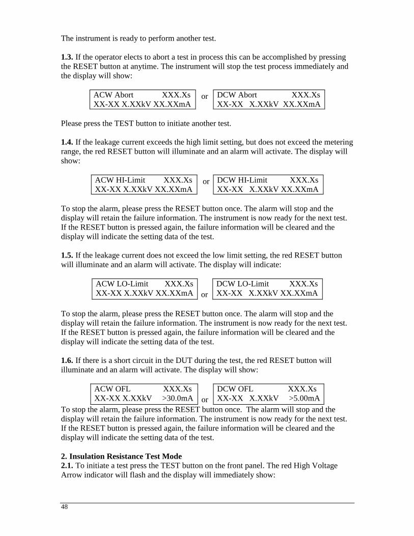
48
The instrument is ready to perform another test.
1.3. If the operator elects to abort a test in process this can be accomplished by pressing
the RESET button at anytime. The instrument will stop the test process immediately and
the display will show:
ACW Abort XXX.Xs
XX-XX X.XXkV XX.XXmA or DCW Abort XXX.Xs
XX-XX X.XXkV XX.XXmA
Please press the TEST button to initiate another test.
1.4. If the leakage current exceeds the high limit setting, but does not exceed the metering
range, the red RESET button will illuminate and an alarm will activate. The display will
show:
ACW HI-Limit XXX.Xs
XX-XX X.XXkV XX.XXmA or DCW HI-Limit XXX.Xs
XX-XX X.XXkV XX.XXmA
To stop the alarm, please press the RESET button once. The alarm will stop and the
display will retain the failure information. The instrument is now ready for the next test.
If the RESET button is pressed again, the failure information will be cleared and the
display will indicate the setting data of the test.
1.5. If the leakage current does not exceed the low limit setting, the red RESET button
will illuminate and an alarm will activate. The display will indicate:
ACW LO-Limit XXX.Xs
XX-XX X.XXkV XX.XXmA
or
DCW LO-Limit XXX.Xs
XX-XX X.XXkV XX.XXmA
To stop the alarm, please press the RESET button once. The alarm will stop and the
display will retain the failure information. The instrument is now ready for the next test.
If the RESET button is pressed again, the failure information will be cleared and the
display will indicate the setting data of the test.
1.6. If there is a short circuit in the DUT during the test, the red RESET button will
illuminate and an alarm will activate. The display will show:
ACW OFL XXX.Xs
XX-XX X.XXkV >30.0mA
or
DCW OFL XXX.Xs
XX-XX X.XXkV >5.00mA
To stop the alarm, please press the RESET button once. The alarm will stop and the
display will retain the failure information. The instrument is now ready for the next test.
If the RESET button is pressed again, the failure information will be cleared and the
display will indicate the setting data of the test.
2. Insulation Resistance Test Mode
2.1. To initiate a test press the TEST button on the front panel. The red High Voltage
Arrow indicator will flash and the display will immediately show:

49
IR Set XXX.Xs
XX-XX XXXXV XXXXMΩ then IR Delay
XXX.Xs
XX-XX XXXXV
XXXXMΩ
2.2. If the DUT has passed the test, the green TEST button will illuminate and a short
audible beep will be activated. The display will show:
IR Pass XXX.Xs
XX-XX XXXXV
XXXXMΩ
The instrument is ready to perform another test.
2.3. If the operator elects to abort a test in process this can be accomplished by pressing
the RESET button at anytime. The instrument will stop the test process immediately and
the display will show:
IR Abort XXX.Xs
XX-XX XXXXV
XXXXMΩ
Press the TEST button to initiate another test.
2.4. If the insulation resistance exceeds the high limit setting, the red RESET button will
illuminate and an alarm will activate. The display will show:
IR HI-Limit
XXX.Xs
XX-XX XXXXV
XXXXMΩ
To stop the alarm, please press the RESET button once. The alarm will stop and the
display will retain the failure information. The instrument is now ready for the next test.
If the RESET button is pressed again, the failure information on the screen will be
cleared and the display will indicate the setting data of the previous test.
2.5. If the insulation resistance does not exceed the low limit setting and is within the
metering range the red RESET button will illuminate and an alarm will activate. The
display will show:
IR LO-Limit
XXX.Xs
XX-XX XXXXV
XXXXMΩ

50
To stop the alarm, please press the RESET button once. The alarm will stop and the
display will retain the failure information. The instrument is now ready for the next test.
If the RESET button is pressed again, the failure information on the screen will be
cleared and the display will indicate the setting data of the test.
3. Ground Bond Test Mode
3.1. To initiate a test press the TEST button on the front panel. The instrument will
continue to output the desired current for the duration of the selected dwell time. The
display will indicate:
GND Set XXX.Xs
XX-XX XX.XA XXXmΩ then GND Dwell XXX.Xs
XX-XX XX.XA XXXmΩ
3.2. If the DUT has passed the test, the green TEST button will illuminate and a short
audible beep will be activate. The display will indicate:
The instrument is ready to perform another test.
3.3. If the operator elects to abort a test in process this can be accomplished by pressing
the RESET button at anytime. The instrument will stop the test process immediately. The
display will indicate:
Please press the TEST button to initiate another test
3.4. If the resistance exceeds the metering range, the red RESET button will illuminate
and the alarm will be activate. The display will show:
If current
3.0 – 10.0A
If current
10.1 – 25.0A
If current
25.1 – 30.0A
GND Pass XXX.Xs
XX-XX XX.XA XXXmΩ
GND Abort XXX.Xs
XX-XX XX.XA XXXmΩ
X – X HI-Lmt XXX.Xs
XX.XA GND >510m
X – X HI-Lmt XXX.Xs
XX.XA GND >200m
X – X HI-Lmt XXX.Xs
XX.XA GND >150m

51
To stop the alarm, press the RESET button once. The alarm will stop and the display will
retain the failure information. The instrument is now ready for the next test. If the RESET
button is pressed again, the failure information will be cleared and the display will
indicate the setting data of the test. The display will show:
3.5. If the resistance exceeds the high limit trip setting but does not exceed the metering
range, the red RESET button will illuminate and the alarm will be activated. The display
will show:
To stop the alarm, press the RESET button once. The alarm will stop and the display will
retain the failure information. The instrument is now ready for the next test. If the RESET
button is pressed again, the failure information will be cleared and the display will
indicate the setting data of the test.
3.6. If the resistance does not exceed the low limit setting, the red RESET button will
illuminate and the alarm will be activated. The display will show:
To stop the alarm, press the RESET button once. The alarm will stop and the display will
retain the failure information. The instrument is now ready for the next test. If the RESET
button is pressed again, the failure information will be cleared and the display will
indicate the setting data of the test.
4. Functional Run test mode
4.1. To initiate a test, press the TEST button on the front panel. The display will
immediately show:
The instrument will continue to output the desired voltage for the duration of the selected
Delay and Dwell times. Use the Up () or Down () arrow keys to bring up an alternate
display screen while the test is running. The alternate display screen will show:
4.2. If the DUT has passed the test, the green
TEST button will illuminate and a short audible beep will activate. The display will
show:
GND Set XXX.Xs
XX-XX XX.XA XXXmΩ
GND Hi-Limit XXX.Xs
XX-XX XX.XA XXXmΩ
GND LO-Limit XXX.Xs
XX-XX XX.XA XXXmΩ
RUN Set XXX.Xs
XX-XX XX.XV XX.XA
then
RUN Delay XXX.Xs
XX-XX XX.XV XX.XA
RUN Dwell X.XX mA
XX.XX XW
X.XXXPF

52
Use the Up () or Down () arrow keys to bring up an alternate display screen after the
test has completed. The alternate display will show:
The instrument is ready to perform another test.
4.3. If the operator elects to abort a test in process this can be accomplished by pressing
the RESET button at anytime. The instrument will stop the test process immediately and
the display will show:
Please press the TEST button to initiate another test.
4.4. If the DUT input voltage exceeds the high limit setting or does not exceed the low
limit setting, the red RESET button will illuminate and an alarm will activate. The
display will show:
RUN Volt-HI XXX.Xs
XX-XX XX.XV XX.XA
or RUN Volt-LO
XXX.Xs
XX-XX XX.XV XX.XA
To stop the alarm, press the RESET button once. The alarm will stop and the display will
retain the failure information. The instrument is now ready for the next test. If the RESET
button is pressed again, the failure information will be cleared and the display will
indicate the setting data of the test.
4.5. If the DUT input current exceeds the high limit setting or does not exceed the low
limit setting, the red RESET button will illuminate and an alarm will activate. The
display will show:
RUN Amp-HI XXX.Xs
XX-XX XX.XV XX.XA
or RUN Amp-LO XXX.Xs
XX-XX XX.XV
XX.XA
To stop the alarm, please press the RESET button once. The alarm will stop and the
display will retain the failure information. The instrument is now ready for the next test.
If the RESET button is pressed again, the failure information will be cleared and the
display will indicate the setting data of the test.
4.6. If the DUT input power exceeds the high limit setting or does not exceed the low
limit setting, the red RESET button will illuminate and an alarm will activate. The
display will show:
RUN Pass XXX.Xs
XX-XX XX.XV XX.XA
RUN Pass X.XX mA
XX-XX XW X.XXXPF
RUN Abort XXX.Xs
XX-XX XX.XV XX.XA

53
RUN Power-HI XXX.Xs
XX-XX XX.XV XX.XA
or RUN Power-LO XXX.Xs
XX-XX XX.XV XX.XA
To stop the alarm, please press the RESET button once. The alarm will stop and the
display will retain the failure information. The instrument is now ready for the next test.
If the RESET button is pressed again, the failure information will be cleared and the
display will indicate the setting data of the test.
4.7. If the DUT input power factor (PF) exceeds the high limit setting or does not exceed
the low limit setting, the red RESET button will illuminate and an alarm will activate.
The display will show:
RUN PF-HI
XXX.Xs
XXX-X XX.XV XX.XA
or RUN PF-LO
XXX.Xs
XX-XX XX.XV XX.XA
To stop the alarm, please press the RESET button once. The alarm will stop and the
display will retain the failure information. The instrument is now ready for the next test.
If the RESET button is pressed again, the failure information will be cleared and the
display will indicate the setting data of the test.
4.8. If the leakage current exceeds the high limit setting, but does not exceed the metering
range, or does not exceed the low limit setting, the red RESET button will illuminate and
an alarm will activate. The display will show:
RUN Leakage-HI
XXX.Xs
XX-XX XX.XV XX.XA
or RUN Leakage-LO
XXX.Xs
XX-XX XX.XV XX.XA
To stop the alarm, please press the RESET button once. The alarm will stop and the
display will retain the failure information. The instrument is now ready for the next test.
If the RESET button is pressed again, the failure information will be cleared and the
display will indicate the setting data of the test.
4.9. If there is a short circuit in the DUT causing excessive line current during the test,
the red RESET button will illuminate and an alarm will activate. The display will show:
RUN Line-OC XXX.Xs
XX-XX XX.XV XX.XA
To stop the alarm, please press the RESET button once. The alarm will stop and the
display will retain the failure information. The instrument is now ready for the next test.
If the RESET button is pressed again, the failure information will be cleared and the
display will indicate the setting data of the test.
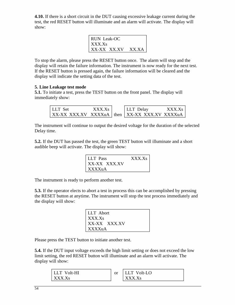
54
4.10. If there is a short circuit in the DUT causing excessive leakage current during the
test, the red RESET button will illuminate and an alarm will activate. The display will
show:
RUN Leak-OC
XXX.Xs
XX-XX XX.XV XX.XA
To stop the alarm, please press the RESET button once. The alarm will stop and the
display will retain the failure information. The instrument is now ready for the next test.
If the RESET button is pressed again, the failure information will be cleared and the
display will indicate the setting data of the test.
5. Line Leakage test mode
5.1. To initiate a test, press the TEST button on the front panel. The display will
immediately show:
LLT Set XXX.Xs
XX-XX XXX.XV XXXXuA
then
LLT Delay XXX.Xs
XX-XX XXX.XV XXXXuA
The instrument will continue to output the desired voltage for the duration of the selected
Delay time.
5.2. If the DUT has passed the test, the green TEST button will illuminate and a short
audible beep will activate. The display will show:
LLT Pass XXX.Xs
XX-XX XXX.XV
XXXXuA
The instrument is ready to perform another test.
5.3. If the operator elects to abort a test in process this can be accomplished by pressing
the RESET button at anytime. The instrument will stop the test process immediately and
the display will show:
LLT Abort
XXX.Xs
XX-XX XXX.XV
XXXXuA
Please press the TEST button to initiate another test.
5.4. If the DUT input voltage exceeds the high limit setting or does not exceed the low
limit setting, the red RESET button will illuminate and an alarm will activate. The
display will show:
LLT Volt-HI
XXX.Xs
or LLT Volt-LO
XXX.Xs

55
XX-XX XX.XV
XXXXuA
XX-XX XX.XV XXXXuA
To stop the alarm, please press the RESET button once. The alarm will stop and the
display will retain the failure information. The instrument is now ready for the next test.
If the RESET button is pressed again, the failure information will be cleared and the
display will indicate the setting data of the test.
5.5. If the DUT leakage current exceeds the high limit setting or does not exceed the low
limit setting, the red RESET button will illuminate and an alarm will activate. The
display will show:
LLT Leakage-HI
XXX.Xs
XX-XX XX.XV XXXXuA
or LLT Leakage-LO
XXX.Xs
XX-XX XX.XV XXXXuA
To stop the alarm, please press the RESET button once. The alarm will stop and the
display will retain the failure information. The instrument is now ready for the next test.
If the RESET button is pressed again, the failure information will be cleared and the
display will indicate the setting data of the test.
5.6. If there is a short circuit in the DUT during the test, the red RESET button will
illuminate and an alarm will activate. The display will show:
LLT Line-OC
XXX.Xs
XX-XX XX.XV XXXXuA
To stop the alarm, please press the RESET button once. The alarm will stop and the
display will retain the failure information. The instrument is now ready for the next test.
If the RESET button is pressed again, the failure information will be cleared and the
display will indicate the setting data of the test.
5.7. If there is a short circuit in the DUT during the test, the red RESET button will
illuminate and an alarm will activate. The display will show:
LLT Leak-OC XXX.Xs
XX-XX XX.XV XXXXuA
To stop the alarm, please press the RESET button once. The alarm will stop and the
display will retain the failure information. The instrument is now ready for the next test.
If the RESET button is pressed again, the failure information will be cleared and the
display will indicate the setting data of the test.
5.8. If the DUT Input Voltage is wired incorrectly the red RESET button will illuminate
and an alarm will activate. The display will show:

56
LLT Neutral-V XXX.Xs
XX-XX XX.XV XXXXuA
To stop the alarm, please press the RESET button once. The alarm will stop and the
display will retain the failure information. The instrument is now ready for the next test.
If the RESET button is pressed again, the failure information will be cleared and the
display will indicate the setting data of the test.
6. Reviewing Test Result in multi-step tests
The test results from the memories that have been executed can be reviewed by pressing
the Up () or Down () arrow keys. Successive key presses will continue advancing to
the next result. The results of the last step in the process will be followed by the first step.
Results can be reviewed at any time before the next test is executed. All results are
cleared at the start of the next test cycle.
7. Output Error
This message appears on the display if the instrument’s output reading does not match the
setting. When the instrument has an output problem and the TEST button is pressed, the
Output Error screen will appear as follows:
The RESET button is not active in this situation. Only the EXIT key will allow you to
return to the test mode. When the EXIT key is pressed the instrument will continue with
its normal failure indication process. The failure light and alarm can be cleared by
pressing the RESET button. If Output Error occurs please call the Slaughter Company
Customer Support Center at 1-800-504-0055 for assistance.
8. Fatal Error
If the instrument has a Fatal Error failure then the following screen will appear:
None of the buttons and keys will be active in this situation. This type of failure
permanently locks the instrument in the Fatal Error mode and requires that the instrument
be serviced by the Slaughter Company. The customer should contact the Slaughter
Company Customer Support Center at 1-800-504-0055 to receive further instruction.
The following Fatal Error identification numbers will represent the type of the failure that
has occurred:
FATAL ERROR 9001 will appear on the display, if the instrument has a recognizable
internal component failure.
FATAL ERROR 9002 will appear on the display, if the instrument’s System data or the
Model/Option data are corrupted and do not match the setting.
OUTPUT ERROR!
EXIT to continue
FATAL ERROR 900X
Call 18005040055

57
FATAL ERROR 9003 will appear on the display, if the instrument’s Calibration data is
corrupted.
FATAL ERROR 9004 will appear on the display, if the instrument has an internal data
transfer error.

58
CONNECTION OF REMOTE I/O
Two 9-pin “D” type connectors are mounted on the rear panel that provides REMOTE-
INPUT-OUTPUT control and information. These connectors mate with standard 9 pin
D-sub-miniature connector provided by the user. The output mates to a male (plug)
connector while the input mates to a female (receptacle) connector. For best
performance, a shielded cable should be used. To avoid ground loops the shield should
not be grounded at both ends of the cable. Suggested AMP part numbers for
interconnecting to the Remote I/O are shown below:
205204-4 PLUG SHELL WITH GROUND INDENTS
205203-3 RECEPTACLE SHELL
745254-7 CRIMP SNAP-IN PIN CONTACT (for plug)
745253-7 CRIMP SNAP-IN SOCKET CONTACT (for receptacle)
745171-1 SHIELDED CABLE CLAMP (for either plug or receptacle)
747784-3 JACKSCREW SET (2)
Remote Interface Rear Panel
SIGNAL OUTPUTS ON REMOTE I/O The rear panel connector provides output signals to remotely monitor PASS, FAIL, and
PROCESSING conditions. These signals are provided by three normally open internal
relays that switch on to indicate the current condition of the tester. These are normally
open free contacts and will not provide any voltage or current. The ratings of the
contacts are 1A / 250 VAC ( 0.5 ADC ). Below is a listing that indicates what conditions
activate each pin. When a terminal becomes active, the relay closes thereby allowing the
external voltage to operate an external device.
Pins 1 and 2 provide the PASS signal.
Pins 3 and 4 provide the FAIL signal.
Pins 5 and 6 provide the PROCESSING signal.
The following describes how the relays operate for each test condition.
BIT 2
COMMON
BIT 1
6 9
SIGNAL INPUT
1
BIT 3
5
INTERLOCK
TEST
RESET
SIGNAL OUTPUT
PROCESSING
5
9
FAIL
1
6
PASS

59
PROCESSING - The relay contact closes the connection between pin (5) and pin (6)
while the instrument is performing a test. The connection is opened at the end of the test.
PASS - The relay contact closes the connection between pin (1) and pin (2) after
detecting that the item under test passed all tests. The connection is opened when the
next test is initiated or the reset function is activated.
FAIL - The relay contact closes the connection between pin (3) and pin (4) after detecting
that the item under test failed any test. The connection is opened when the next test is
initiated or the reset function activated.
SIGNAL INPUTS OF REMOTE I/O and PROGRAMMED TESTS
The model 6330 remote connector enables remote operation of the TEST, RESET, and
REMOTE INTERLOCK functions, and allows the operator to select one of 6
preprogrammed tests.
When the PLC Remote mode is ON, the instrument will respond to simple switch or relay
contacts closures. A normally open momentary switch can then be wired across pins 3
and 5 to allow remote operation of the TEST function. When the PLC Remote function is
ON the TEST button on the front panel will be disabled to prevent a test from being
activated through this button. If you attempt to start a test from the front panel TEST
button and the PLC Remote function is turned “ON”, a pop-up message will be
displayed. The pop-up message will appear as follows
A normally open momentary switch can also be wired across pins 2 and 5 to allow
remote operation of the RESET function. For safety, the front panel RESET button
remains active even when a remote reset switch is connected so that high voltage can be
shut down from either location.
The Remote Test Select function gives the user the capability to quickly change
parameters and initiate a test remotely. Six pre-programmed tests can be accessed by
connecting pins 1, 8, and 9 to the common pin 7, in different combinations. The memory
select bits should be set simultaneously and remain set for a minimum of 20ms to
guarantee that the correct memory will be selected. However, the memory select bits
may be set in sequential manner, provided that the time delay between each bit is less
than 4ms. When the desired bit pattern has been established it should remain set for a
minimum of 20ms to guarantee that the correct memory will be selected. The Remote
Tests Select Truth Table (binary) shows the different combinations of momentary
switch (relay) closures, and which memory programs that will be selected as the result. It
may be necessary to "OR" the momentary switches (relay contacts) to prevent incorrect
program selection due to timing errors.
Remote Tests Select Truth Table
BIT 3 BIT 2 BIT 1 TEST #
0 0 1 01
0 1 0 02
PLC Remote ON
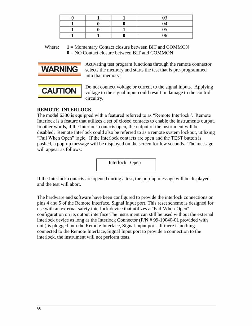
60
0 1 1 03
1 0 0 04
1 0 1 05
1 1 0 06
Where: 1 = Momentary Contact closure between BIT and COMMON
0 = NO Contact closure between BIT and COMMON
Activating test program functions through the remote connector
selects the memory and starts the test that is pre-programmed
into that memory.
Do not connect voltage or current to the signal inputs. Applying
voltage to the signal input could result in damage to the control
circuitry.
REMOTE INTERLOCK
The model 6330 is equipped with a featured referred to as “Remote Interlock”. Remote
Interlock is a feature that utilizes a set of closed contacts to enable the instruments output.
In other words, if the Interlock contacts open, the output of the instrument will be
disabled. Remote Interlock could also be referred to as a remote system lockout, utilizing
“Fail When Open” logic. If the Interlock contacts are open and the TEST button is
pushed, a pop-up message will be displayed on the screen for few seconds. The message
will appear as follows:
If the Interlock contacts are opened during a test, the pop-up message will be displayed
and the test will abort.
The hardware and software have been configured to provide the interlock connections on
pins 4 and 5 of the Remote Interface, Signal Input port. This reset scheme is designed for
use with an external safety interlock device that utilizes a "Fail-When-Open"
configuration on its output interface The instrument can still be used without the external
interlock device as long as the Interlock Connector (P/N # 99-10040-01 provided with
unit) is plugged into the Remote Interface, Signal Input port. If there is nothing
connected to the Remote Interface, Signal Input port to provide a connection to the
interlock, the instrument will not perform tests.
Interlock Open

61
INSTRUMENT CONNECTIONS
The Slaughter 6330 comes with test leads to perform all necessary safety tests. The
following test leads are included with the instrument:
Part Number Description
99-10467-01 Adapter Box
99-10457-01 LLT CASE LEAD
99-10468-01 LLT GROUND
LEAD
99-10009-01 GND BND
OUTPUT
99-10008-01 RETURN LEAD
99-10469-01 LLT INPUT LINE
99-10470-01 LLT INPUT
NEUTRAL
99-10471-01 LLT OUTPUT
LINE
99-10472-01 LLT OUTPUT
NEUTRAL
102-055-913 High Voltage Cable
Functional Run/Line Leakage stand-alone test lead connections In order to perform a Line Leakage and/or Functional Run test, an external power supply
must be used to provide power to the device under test.
The power supply must be an unbalanced, single phase 0-277
VAC supply. Using a balanced supply may cause damage to the
instrument or operator.
Provided with the instrument are two 10 AWG input power leads (terminated on one end)
that may be connected to the 6330’s DUT Power In screw-mount terminals (line and
neutral). These leads are left un-terminated at the other end and should be connected to
the outputs of the power supply. The 10 AWG input power leads may be used for
applications in which the DUT requires more than 20 Amps of input current.
Provided with the instrument are two 10 AWG output power leads (terminated on one
end) that may be used to connect to the 6330’s DUT Power Out screw-mount terminals
(line and neutral). These leads are left un-terminated at the other end and should be
connected to the device under test for applications that require more than 20 Amps of
input current
The following diagram shows how to connect the stand alone test leads to the 6330 and to
the device under test:

62
99-10471-01 LINE99-10472-01 NEUTRAL
99-10468-01 EARTH GROUND
99-10457-01
LINE CONNECTIONS
DUT
CHASSIS
DUT I.E. AC FAN
99-10470-01 NEUTRAL
99-10469-01 LINE
AC SOURCE
0-277VAC
YOUR
TEST
FIXTURE
Adapter Box connections In addition to the stand-alone test leads, the instrument also comes with an adapter box.
The adapter box allows the user an easy way to connect an item that is terminated in a
three-prong line cord. Note: the adapter box may only be connected to the rear panel of
the 6330. The following diagram shows how to connect the adapter box to the 6330 and
to the device under test.
LINE
NEUTRAL
99-10467-01
99-10457-01
LINECORD
DUT
CHASSIS
DUT I.E. AC FAN
CAUTIONHIGH VOLTAGE5KVAC MAX.6KVDC MAX.
20A MAX. LINE CURRENT.
NL
EARTH GROUND99-10469-01 LINE
99-10470-01 NEUTRAL
AC SOURCE
0-277VAC
The adapter box (P/N 99-10467-01) may be used to perform
Hipot, Ground Bond, Insulation Resistance, Functional Run, and
Line Leakage tests. The adapter box is rated for a maximum of
20 Amps of input current. If current levels greater than 20 Amps are needed for either the
Functional Run test or the Line Leakage test, the stand alone test leads must be used.

63
Bus Remote Interface: RS-232 This section provides information on the proper use and configuration of bus remote
interface. The RS-232 remote interface is standard on all 6330 models.
RS-232 Interface This interface provides all of the control commands and parameter setting commands. All
commands can be found in the command list of this manual.
The RS-232 cabling should be configured as follows for a 9-pin serial port interface:
The COM port should have the following configuration. 9600 baud, 8 data bits, 1 stop
bit, no parity. This interface does not support XON/XOFF protocol or any hardware
handshaking. The controller should be configured to ignore the handshaking lines DTR
(pin 4), DSR (pin 6), CTS (pin 8) and RTS (pin 7). If the port cannot be configured
through software to ignore the lines then the handshake lines should be jumpered together
in two different sets. Pins 4 and 6 jumpered together and pins 7 and 8 jumpered together
at the controller end of the cable.
When sending command over the RS232 bus, the instrument will send a response string
of 06 hex or 6 decimal, the Acknowledge (ACK) ASCII control code if the transfer was
recognized and completed by the instrument. If there is an error with the command string
that is sent, the instrument will respond with 15 hex or 21 decimal, the Not Acknowledge
(NAK) ASCII control code. The ACK or NAK response allows for software
handshaking, to monitor and control data flow. When requesting data from the
instrument, it will automatically send the data back to the controller input buffer. The
controller input buffer will accumulate data being sent from the instrument including the
ACK and NAK response strings, until it has been read by the controller.
RS-232 Interface Command List The RS-232 bus will automatically send any response back to the controller's input
buffer. Note that the commands are case sensitive and must be typed in capital letters.
Each command string should be terminated by the ASCII control code, New Line <NL>,
or OAh.
The following conventions are used to describe the commands syntax for the 6330.
Braces ( ) enclose each parameter for a command string. Triangle brackets (< >)
indicate that you must substitute a value for the enclosed parameter. The Pipe ( | ) is used
to separate different parameter options for a command. The command and the parameter
data must be separated with a space. All commands that end with a question mark (?) are
Instrument RS-232 Port PC / Bus Controller
2
3
5
2
3
5
TD
RD
TD
RD
SIG
GND
SIG
GND
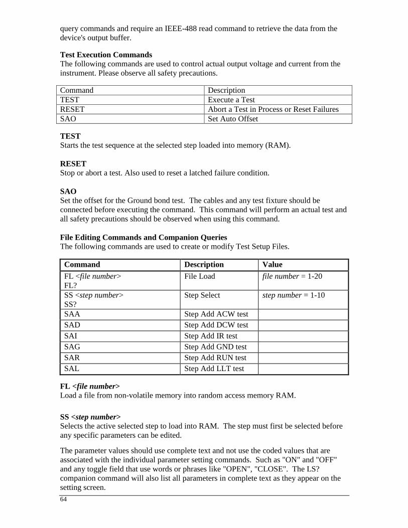
64
query commands and require an IEEE-488 read command to retrieve the data from the
device's output buffer.
Test Execution Commands
The following commands are used to control actual output voltage and current from the
instrument. Please observe all safety precautions.
Command Description
TEST Execute a Test
RESET Abort a Test in Process or Reset Failures
SAO Set Auto Offset
TEST
Starts the test sequence at the selected step loaded into memory (RAM).
RESET
Stop or abort a test. Also used to reset a latched failure condition.
SAO
Set the offset for the Ground bond test. The cables and any test fixture should be
connected before executing the command. This command will perform an actual test and
all safety precautions should be observed when using this command.
File Editing Commands and Companion Queries
The following commands are used to create or modify Test Setup Files.
Command Description Value
FL <file number>
FL?
File Load file number = 1-20
SS <step number>
SS?
Step Select step number = 1-10
SAA Step Add ACW test
SAD Step Add DCW test
SAI Step Add IR test
SAG Step Add GND test
SAR Step Add RUN test
SAL Step Add LLT test
FL <file number>
Load a file from non-volatile memory into random access memory RAM.
SS <step number>
Selects the active selected step to load into RAM. The step must first be selected before
any specific parameters can be edited.
The parameter values should use complete text and not use the coded values that are
associated with the individual parameter setting commands. Such as "ON" and "OFF"
and any toggle field that use words or phrases like "OPEN", "CLOSE". The LS?
companion command will also list all parameters in complete text as they appear on the
setting screen.

65
ACW DCW IR
1 Voltage Voltage Voltage
2 Max Limit Max Limit Max Limit
3 Min Limit Min Limit Min Limit
4 Ramp Up Ramp Up Delay
5 Dwell Dwell DUT Output
(ON/OFF)
6 Frequency DUT Output
(ON/OFF)
Connect (ON/OFF)
7 DUT Output (ON/OFF) Connect (ON/OFF)
8 Connect (ON/OFF)
GND RUN LLT
1 Current Voltage-HI Voltage-HI
2 HI-Limit Voltage-LO Voltage-LO
3 LO-Limit Amp-HI Leakage-HI
4 Dwell Amp-LO Leakage-LO
5 Offset Power-HI Delay Time
6 Frequency Power-LO Line (Neutral,Polarity,Ground)
7 Connect
(ON/OFF)
PF-HI Meas. Device
(UL544NP/UL484/UL923,UL471,UL867,UL69
7,IEC60990 Fig4 U2,IEC60950-1,IEC60335-
1,IEC60598-1,IEC60065,IEC61010,UL2601-
1,IEC60601-1,External)
8 PF-LO Delay Time
9 Leakage-HI Connect
10 Leakage-LO
11 Delay
12 Dwell
13 Connect
(ON/OFF)
Test Parameter Editing Commands
These commands are used to modify the test parameter within each step. These
commands require a parameter value to be included with the command. The companion
query command will read the parameter. The writing of the parameter requires that the
unit not be included with the value, only the numeric value should be included with the
command. Also when the query commands are used the response will not include the
units characters. Many of the commands will function the same way for multiple test
types however the input range may be different and therefore used a different possible set
of values.
Command Name Test
Types
Value
ECC 1|0
ECC?
Edit Step Connect ALL 1= On, 0=Off

66
Command Name Test
Types
Value
EC < value >
EC?
Edit Current GND 3.00 - 30.00A
ECH < value >
ECH?
Edit Current-HI RUN 0.00 - 30.00A
ECL < value >
ECL?
Edit Current-Lo RUN 0.00 - 30.00A
EDE < value >
EDE?
Edit Delay IR
RUN
LLT
0.0, 0.5 - 999.9s
0.2 – 999.9s
0.0, 1.0 – 999.9s
0.0 = Continuous
EDO 1|0
EDO?
Edit DUT-Output
Voltage
ACW
DCW
IR
1= On, 0=Off
EDW < value >
EDW?
Edit Dwell ACW
DCW
GND
RUN
0.0, 0.2 – 999.9s
0.0, 0.2 – 999.9s
0.0, 0.5 – 999.9s
0.0, 0.1 – 999.9s
0.0 = Continuous
EF 1|0
EF?
Edit Frequency ACW
GND
1=60Hz, 0=50Hz
EH < value >
EH?
Edit HI-Limit ACW
DCW
IR
GND
0.0 – 30.00mA
0.0 – 5.00mA
0 - 1000M
0 - 150m
ELH < value >
ELH?
Edit Leakage-HI RUN
LLT
0.000 - 10.00mA
0.0 - 6000uA
ELL < value >
ELL?
Edit Leakage-LO RUN
LLT
0.000 - 10.00mA
0.0 - 6000uA
EL < value >
EL?
Edit LO-Limit ACW
DCW
IR
GND
0.0 – 30.00mA
0.0 – 5.00mA
0 - 1000M
0 - 150m
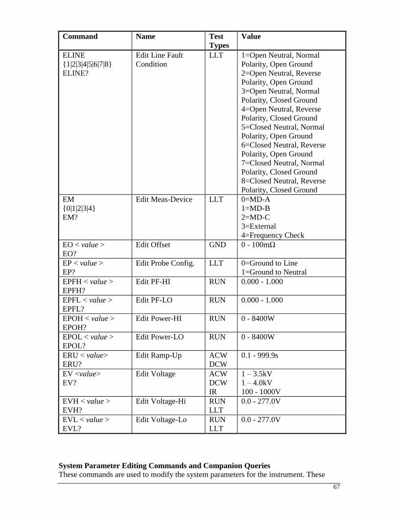
67
Command Name Test
Types
Value
ELINE
1|2|3|4|5|6|7|8
ELINE?
Edit Line Fault
Condition
LLT 1=Open Neutral, Normal
Polarity, Open Ground
2=Open Neutral, Reverse
Polarity, Open Ground
3=Open Neutral, Normal
Polarity, Closed Ground
4=Open Neutral, Reverse
Polarity, Closed Ground
5=Closed Neutral, Normal
Polarity, Open Ground
6=Closed Neutral, Reverse
Polarity, Open Ground
7=Closed Neutral, Normal
Polarity, Closed Ground
8=Closed Neutral, Reverse
Polarity, Closed Ground
EM
0|1|2|3|4
EM?
Edit Meas-Device LLT 0=MD-A
1=MD-B
2=MD-C
3=External
4=Frequency Check
EO < value >
EO?
Edit Offset GND 0 - 100mΩ
EP < value >
EP?
Edit Probe Config. LLT 0=Ground to Line
1=Ground to Neutral
EPFH < value >
EPFH?
Edit PF-HI RUN 0.000 - 1.000
EPFL < value >
EPFL?
Edit PF-LO RUN 0.000 - 1.000
EPOH < value >
EPOH?
Edit Power-HI RUN 0 - 8400W
EPOL < value >
EPOL?
Edit Power-LO RUN 0 - 8400W
ERU < value>
ERU?
Edit Ramp-Up ACW
DCW
0.1 - 999.9s
EV <value>
EV?
Edit Voltage ACW
DCW
IR
1 – 3.5kV
1 – 4.0kV
100 - 1000V
EVH < value >
EVH?
Edit Voltage-Hi RUN
LLT
0.0 - 277.0V
EVL < value >
EVL?
Edit Voltage-Lo RUN
LLT
0.0 - 277.0V
System Parameter Editing Commands and Companion Queries
These commands are used to modify the system parameters for the instrument. These

68
commands require a parameter value to be included with the command.
Command Name Value
SDH1|0
SDH?
DUT HV Setup ON/OFF 1=On, 0=Off
SPR 1|0
SPR?
PLC Remote ON/OFF 1=On, 0=Off
SSI 1|0
SSI?
Single Step ON/OFF 1=On, 0=Off
SF 1|0
SF?
Fail Stop ON/OFF 1=On, 0=Off
SAL <value>
SAL?
Alarm Level 1-9
SL 1|0
SL?
System Lock 1=On, 0=Off
SML 1|0
SML?
System Memory Lock 1=On, 0=Off
Query Commands
These query commands will retrieve data from the instrument. These commands include
functions for retrieving test data, test results and remote hardware.
Command Name Value
TD? List Testing Data Data from test in Process
RD <step number>? Result Data
Query
1-3
RR? Read Reset Query 1=Open, 0=Closed
RI? Read Interlock
Query
1=Open, 0=Closed
LS? List Step
Parameters
LS <step number>? List Step
Parameters by
step number
step number = 1-10
TD?
Read the active data being displayed on the LCD display while the test is in process. It
will also read the last data taken when the test sequence has completed. Each parameter is
separated by commas and includes step number, test type, test status, and metering. The
syntax for this command response is memory - step, test type, status, meter 1, meter 2,
meter 3. Each meter will contain both the value and the units.
RD <step number>?
Read the results for an individual step. The step number is the actual step number that has
been saved within the file, not the order of which the steps were executed. For example if
the test was executed starting from step 3 and ending with step 5 then the first step test
results will be found in location 3 not in location 1. Each parameter is separated by
commas and includes step number, test type, test status, and metering. The syntax for this
command response is memory - step, test type, status, meter 1, meter 2, meter 3. Each
meter will contain both the value and the units.

69
RR?
Read the remote Reset input signal. When the remote reset has be activated by closing the
contacts the query will return a value of 0 to indicate the instrument is being Reset.
RI?
Read the remote Interlock input signal. When the remote Interlock has be activated by
opening the contacts the query will return a value of 1 to indicate the instrument is in the
Interlock state and will not be able to generate output voltage or current.
LS?
Lists all the Parameters for the individual step that is currently selected.
The response will be formatted as follows; <step, test, p1, p2, p3…> Where <step> is the
step number, <test> is the test type and <p1,p2> etc., indicates the parameters of the test.
LS <step number>?
Lists all the Parameters for the individual step indicated by step number = 1-30.
The response will be formatted as follows; <step, test, p1, p2, p3…> Where <step> is the
step number, <test> is the test type and <p1,p2> etc., indicates the parameters of the test.
IEEE 488.2 Common Commands
These commands are required by the IEEE-488.2 standard with the exception of *PSC,
*PSC?. Most of these commands are not available over the RS-232 bus except for the
*IDN? command which can be used to retrieve the instrument identification information,
and the four status reporting commands *ESR?, *ESE, *ESE? and *STB?.
Command Name Description
*IDN? Identification Query SLA, Model Number, Serial
Number, Firmware Revision
*RST Reset Command Resets 6330
*TST? Self-Test Query 00H=OK
01H=TEST EEPROM ERROR
*CLS Clear Status Command Clear Standard Event Status Register
Clear Service Request Register
*OPC Operation Complete Command When TEST command ok setting
ESR BIT0 =1
*OPC? Operation Complete Query 1 = TEST completed ok
0 = TEST in process
*WAI Wait-to-Continue Command
*PSC 1|0 Power-on Status Clear Command 1 = Power-on clear enable registers
0 = Power-on load previous enable
registers
*PSC? Power-on Status Clear Query
*ESR? Standard Event Status Register Query 0 - 255
*ESE <value> Standard Event Status Enable
Command
value = 0 - 255
*ESE? Standard Event Status Enable Query 0 - 255

70
*STB? Read Status Byte Query BIT 0, 01H,(1) Operation Complete
BIT 1,02H,(2) Not Used
BIT 2,04H,(4) Query Error
BIT 3,08H,(8) Device Error
BIT 4,10H,(16) Execution Error
BIT 5,20H,(32) Command Error
BIT 6,40H,(64) Not Used
BIT 7,80H,(128) PROMPT
*SRE <value> Service Request Enable Command value = 0 - 255
*SRE? Service Request Enable Query 0 - 255
*IDN?
Read the instrument identification string. Company =SLA.
*RST
Reset the instrument to original power on configuration. Does not clear Enable register
for Standard Summary Status or Standard Event Registers. Does not clear the output
queue. Does not clear the power-on-status-clear flag.
*TST?
Performs a self test of the instrument data memory. Returns 0 if it is successful or 1 if the
test fails.
*CLS
Clears the Status Byte summary register and event registers. Does not clear the Enable
registers.
*OPC
Sets the operation complete bit (bit 0) in the Standard Event register after a command is
completed successfully.
*OPC?
Returns an ASCII "1" after the command is executed.
*WAI
After the command is executed, it prevents the instrument from executing any further
query or commands until the no-operation-pending flag is TRUE.
*PSC 1|0 Sets the power-on status clear bit. When set to 1 the Standard Event Enable register and
Status Byte Enable registers will be cleared when power is turned ON. 0 setting indicates
the Enable registers will be loaded with Enable register masks from non-volatile memory
at power ON.
*PSC?
Queries the power-on status clear setting. Returns 0 or 1.
*ESR?
Queries the Standard Event register. Returns the decimal value of the binary-weighted
sum of bits.
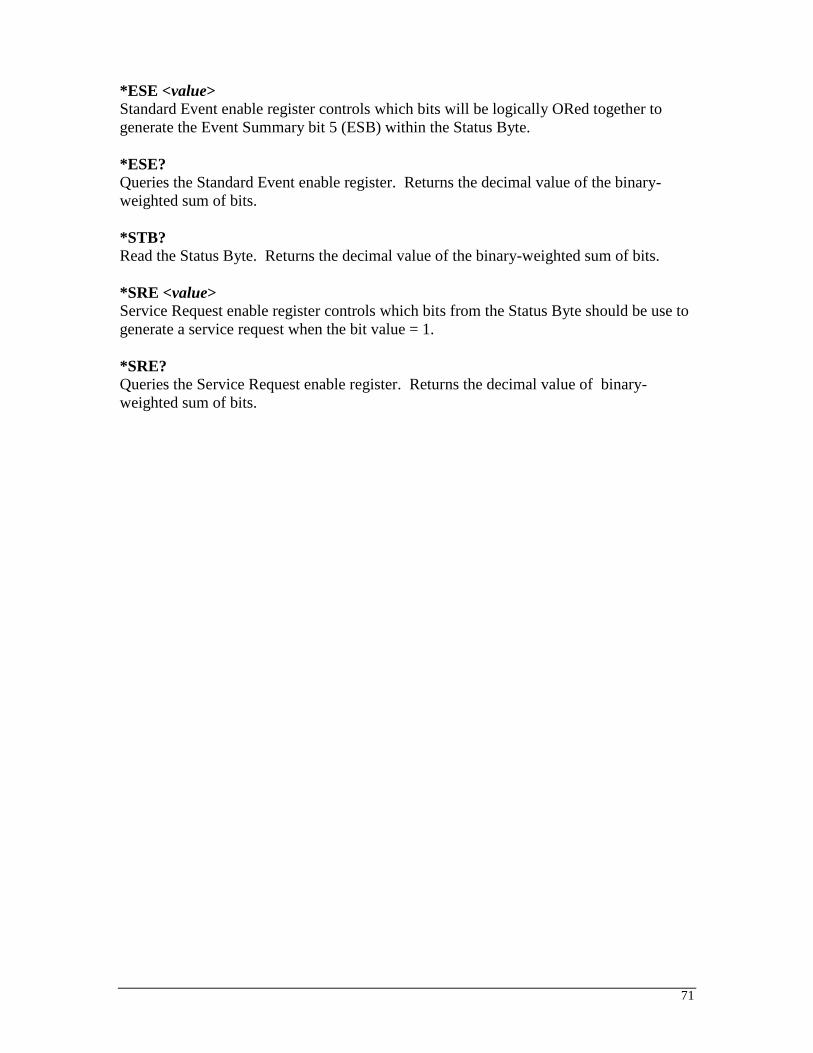
71
*ESE <value>
Standard Event enable register controls which bits will be logically ORed together to
generate the Event Summary bit 5 (ESB) within the Status Byte.
*ESE?
Queries the Standard Event enable register. Returns the decimal value of the binary-
weighted sum of bits.
*STB?
Read the Status Byte. Returns the decimal value of the binary-weighted sum of bits.
*SRE <value>
Service Request enable register controls which bits from the Status Byte should be use to
generate a service request when the bit value = 1.
*SRE?
Queries the Service Request enable register. Returns the decimal value of binary-
weighted sum of bits.
72
MODEL 6330 OPTIONS
Introduction
This section contains a list and descriptions of available factory installed options at the
time of this printing. The list of options contains an option code number which can be
referenced on the model option label on the rear panel of the unit when options are
present.
Model Option Label
On the rear panel of the instrument, you will find a label that contains the option code.
For example, your options code would appear as follows:
fitted with option 01 OPT: 01
fitted with option 01 and 02 OPT: 0102
6330 Options
Option List
Code Description
01 Rack Mount Kit

73
OPTIONS
Option 01 Rack Mount Kit
The optional rack mount kit allows for mounting the 6330 to a standard 19” rack. The
instrument will take 3U’s of rack space. The rack mount kit includes:
Component Qty. Description
99-10458-01 2 Handle Rack Mount 3U
99-10459-01 2 Bracket Rack Mount 3U
99-10448-01 4 Screw M4x12mm Phillips

SECTION 2
SERVICE MANUAL

75
CALIBRATION PROCEDURES
This instrument has been fully calibrated at the factory in accordance to our published
specifications. It has been calibrated with standards traceable to NIST. You will find in
this manual a copy of the "Certificate of Calibration". It is recommended that you have
this instrument recalibrated and a safety check done at least once per year. Slaughter
recommends you use "Calibration Standards" that are NIST traceable, or traceable to
agencies recognized by NIST to keep this instrument within published specifications.
End user metrology standards or practices may vary. These metrology standards
determine the measurement uncertainty ratio of the calibration standards being used.
Calibration adjustments can only be made in the Calibration mode and calibration checks
or verification can only be made while operation in Test mode.
Calibration Equipment Required: The following standard equipment will be needed to properly calibrate your instrument.
A Standard AC Voltmeter with 4,000 Volts range
A Standard AC Voltmeter with 6 Volts range
A Standard DC Voltmeter with 4,000 Volts range
A Standard DC Voltmeter with 1,000 Volts range
A Standard AC Ammeter with 30 A range
A Standard AC Milliammeter with 30 mA range
A Standard DC Milliammeter with 5 mA range
A Standard Resistor 100 k/20Watt/1500VAC
A Standard Resistor 1 M/0.25Watt/300VDC
A Standard Resistor 50 M/0.25Watt/1000VDC
Adjustable AC power supply 0-277VAC, 8.4kVA
Low impedance adjustable load 7Ω – 30Ω , 8400 W
Adjustable DC power supply 0-8VDC
Calibration Initialization
To enter the calibration mode the instrument must be in the OFF position. Using a pen or
small screwdriver, press and hold the recessed calibration key on the rear panel, then turn
on the input POWER switch. The display will show:
To calibrate AC voltage please follow procedure on next paragraph, to calibrate other
parameters use Up () or Down () arrow keys to scroll to the desired calibration point,
then follow procedure on relative paragraph below.
When the calibration process is completed successfully and the instrument accepts the
entered calibration data it will output one short “beep” and advance to the next calibration
point, otherwise the instrument will output two short “beeps” and will not advance to the
next calibration point.
01. AC 4000V

76
1. To calibrate AC Voltage
Please connect a standard 4000V AC Voltmeter to the HV and RETURN connectors.
Then press the TEST button on the front panel. The instrument will provide around
4000VAC on the output connectors and the display will show:
Press the Up () or Down () arrow keys to enter the reading of the standard AC
Voltmeter into the instrument. Then press SET key to store the voltage setting and to
advance to the next calibration point or press the RESET button to return to the
calibration menu without changing the calibration setting. Press the EXIT key to exit
from the calibration mode and to return to the test mode.
2. To calibrate DC Voltage
Please connect a standard 4000V DC Voltmeter to the HV and RETURN connectors.
Press the Up () or Down () arrow keys until the display shows:
Then press the TEST button on the front panel. The instrument will provide around
4000VDC on the output connectors and the display will show:
Press the Up () or Down () arrow keys to enter the reading of the standard DC
Voltmeter into the instrument. Then press SET key to store the voltage setting and to
advance to the next calibration point or press the RESET button to return to the
calibration menu without changing the calibration setting. Press the EXIT key to exit
from the calibration mode and to return to the test mode.
3. To calibrate IR Voltage
Please connect a standard 1000V DC Voltmeter to the HV and RETURN connectors.
Press the Up () or Down () arrow keys until the display shows:
Then press the TEST button on the front panel. The instrument will provide around
1000VDC on the output connectors and the display will show:
Press the Up () or Down () arrow keys to enter the reading of the standard DC
Voltmeter into the instrument. Then press SET key to store the voltage setting and to
advance to the next calibration point or press the RESET button to return to the
Voltage = XXXXV
02. DC 4000V
Voltage = XXXXV
03. IR 1000V
Voltage = XXXXV

77
calibration menu without changing the calibration setting. Press the EXIT key to exit
from the calibration mode and to return to the test mode.
4. To calibrate AC Current
Please connect a 100 k resistor in series with the standard 30mA AC Milliammeter and
connect these across the HV and RETURN connectors of the instrument.
Press the Up () or Down () arrow keys until the display shows:
Then press the TEST button on the front panel. The instrument will provide around
1000VAC on the output connectors and the display will show:
Press the Up () or Down () arrow keys to enter the reading of the standard AC
Milliammeter into the instrument. Then press SET key to store the current setting and to
advance to the next calibration point or press the RESET button to return to the
calibration menu without changing the calibration setting. Press the EXIT key to exit
from the calibration mode and to return to the test mode.
5. To calibrate DC Current
Please connect a 100 k resistor in series with the standard 5mA DC Milliammeter and
connect these across the HV and RETURN connectors of the instrument.
Press the Up () or Down () arrow keys until the display shows:
Then press the TEST button on the front panel. The instrument will provide around
500VDC on the output connectors and the display will show:
Press the Up () or Down () arrow keys to enter the reading of the standard DC
Milliammeter into the instrument. Then press SET key to store the current setting and to
advance to the next calibration point or press the RESET button to return to the
calibration menu without changing the calibration setting. Press the EXIT key to exit
from the calibration mode and to return to the test mode.
6. To calibrate Insulation Resistance low range
Please connect a 100k standard resistor across the HV and RETURN connectors.
Press the Up () or Down () arrow keys until the display shows:
04. AC 30.00mA
Load = 100k
Current XX.XXmA
05. DC 5.00mA
Load = 100k
Current X.XXmA
06. IR 0.99M
Load = 100k

78
Then press the TEST button on the front panel. The instrument will execute automatic
calibration process. The process does not require data entry. The instrument will provide
around 300VDC on the output connectors and the display will show:
The instrument will output one short “beep” and advance to the next calibration point
when the automatic process is completed successfully, otherwise the instrument will
output two short “beeps” and will not advance to the next calibration point.
7. To calibrate Insulation Resistance mid range 1
When previous calibration point was completed successfully display will show:
Please connect a 1M standard resistor across the HV and RETURN connectors.
Then press the TEST button on the front panel. The instrument will execute automatic
calibration process. The process does not require data entry. The instrument will provide
around 300VDC on the output connectors and the display will show:
The instrument will output one short “beep” and advance to the next calibration point
when the automatic process is completed successfully, otherwise the instrument will
output two short “beeps” and will not advance to the next calibration point.
8. To calibrate Insulation Resistance mid range 2
When previous calibration point was completed successfully display will show:
Please connect a 50M standard resistor across the HV and RETURN connectors.
Then press the TEST button on the front panel. The instrument will execute automatic
calibration process. The process does not require data entry. The instrument will provide
around 1000VDC on the output connectors and the display will show:
Automatic
07. IR 9.99M
Load = 1M
Automatic
08. IR 99.99M
Load = 50M
Automatic

79
The instrument will output one short “beep” and advance to the next calibration point
when the automatic process is completed successfully, otherwise the instrument will
output two short “beeps” and will not advance to the next calibration point.
9. To calibrate Insulation Resistance high range
When previous calibration point was completed successfully display will show:
The 50M standard resistor should be connected across the HV and RETURN
connectors of the instrument.
Then press the TEST button on the front panel. The instrument will execute automatic
calibration process. The process does not require data entry. The instrument will provide
around 150VDC on the output connectors and the display will show:
The instrument will output one short “beep” and advance to the next calibration point
when the automatic process is completed successfully, otherwise the instrument will
output two short “beeps” and will not advance to the next calibration point.
10. To calibrate Ground Bond test voltage
Please connect a standard 6V AC Voltmeter across the CURRENT and RETURN
connectors of the instrument.
Press the Up () or Down () arrow keys until the display shows:
Then press the TEST button on the front panel. The instrument will generate an output of
about 6 VAC and the display will show:
Press the Up () or Down () arrow keys to enter the reading of the standard AC
Voltmeter into the instrument. Then press SET key to store the voltage setting and to
advance to the next calibration point or press the RESET button to return to the
calibration menu without changing the calibration setting. Press the EXIT key to exit
from the calibration mode and to return to the test mode.
11. To calibrate Ground Bond test current
Please connect the standard 30A AC Ammeter across the CURRENT and RETURN
connectors of the instrument.
Press the Up () or Down () arrow keys until the display shows:
09. IR 999.9M
Load = 50M
Automatic
10. GND 6.00V
Voltage = X.XXV
11. GND 30.0A

80
Then press the TEST button on the front panel. The display will show:
Press the Up () or Down () arrow keys to enter the reading of the standard AC
Ammeter into the instrument. Then press SET key to store the current setting and to
advance to the next calibration point or press the RESET button to return to the
calibration menu without changing the calibration setting. Press the EXIT key to exit
from the calibration mode and to return to the test mode.
12. To calibrate Functional Run test voltage
Step 1
Please disconnect all meters from the instrument.
Press the Up () or Down () arrow keys until the display shows:
Then press the TEST button on the front panel. Then press SET key to advance to the
next calibration point or press the RESET button to return to the calibration menu without
changing the calibration setting. Press the EXIT key to exit from the calibration mode
and to return to the test mode.
Step 2
Please connect the standard 0-277VAC power supply to the DUT I/P inputs of the
instrument. Connect the standard AC voltmeter to the DUT outputs.
Press the Up () or Down () arrow keys until the display shows:
Then press the TEST button on the front panel. The display will show:
Press the Up () or Down () arrow keys to enter the reading of the standard AC
voltmeter into the instrument. Then press SET key to store the current setting and to
advance to the next calibration point or press the RESET button to return to the
calibration menu without changing the calibration setting. Press the EXIT key to exit
from the calibration mode and to return to the test mode.
13. To calibrate the Functional Run test current
Current = XX.XA
12. RUN 277.0V
Step 1: No Power Input
12. RUN Voltage
Step 2: ACV 250V Input
Automatic

81
Please connect a 30A resistor in series with the standard 30AAC ammeter and connect
these across the DUT Output Power Line and Neutral terminals.
Press the Up () or Down () arrow keys until the display shows:
Then press the TEST button on the front panel and the display will show:
Press the Up () or Down () arrow keys to enter the reading of the standard AC
ammeter into the instrument. Then press SET key to store the current setting and to
advance to the next calibration point or press the RESET button to return to the
calibration menu without changing the calibration setting. Press the EXIT key to exit
from the calibration mode and to return to the test mode
14. To calibrate the Functional Run test power
Please connect a 10Ω resistor in series with the standard power meter’s current inputs.
Connect the power meter’s voltage inputs to the DUT Output Line and Neutral terminals
of the instrument. Connect the AC power supply to the DUT I/P connectors of the
instrument and set the voltage for 225VAC.
Press the Up () or Down () arrow keys until the display shows:
Then press the TEST button on the front panel and the display will show:
Press the Up () or Down () arrow keys to enter the reading of the power meter into the
instrument. Then press SET key to store the current setting and to advance to the next
calibration point or press the RESET button to return to the calibration menu without
changing the calibration setting. Press the EXIT key to exit from the calibration mode
and to return to the test mode
15. To calibrate the Functional Run test leakage current
13. RUN 30.0A
L=30Amp,V=120-277VAC
Current = XX.XA
14. RUN 8400W
L=10Ω, V=220VAC
Power = XXXXW

82
Please connect a standard Milliammeter to the DUT Power Outputs Line and Ground
terminals. Connect the AC power supply to the DUT I/P of the instrument and set the
voltage to 18VAC.
Press the Up () or Down () arrow keys until the display shows:
Then press the TEST button on the front panel and the display will show:
Press the Up () or Down () arrow keys to enter the reading of the standard AC
Milliammeter into the instrument. Then press SET key to store the current setting and to
advance to the next calibration point or press the RESET button to return to the
calibration menu without changing the calibration setting. Press the EXIT key to exit
from the calibration mode and to return to the test mode
16. To calibrate the Line Leakage test offset
Please disconnect all meters from the instrument.
Press the Up () or Down () arrow keys until the display shows:
Then press the TEST button on the front panel and the display will show:
Then press SET key to advance to the next calibration point or press the RESET button to
return to the calibration menu without changing the calibration setting. Press the EXIT
key to exit from the calibration mode and to return to the test mode.
17. To calibrate the Line Leakage test x1
Please connect a standard voltmeter and DC power supply in parallel to the DUT Input
terminals. Place the power supply’s positive output (+) to the instrument’s Neutral
terminal. Place the power supply’s negative output (-) to the instrument’s Ground
terminal. Set the DC power supply to 8VDC.
Press the Up () or Down () arrow keys until the display shows:
15. RUN 10.0mA
DUT I/P=18VAC
Current = X.XXmA
16. LLT Offset
Automatic
17. LLT X1
N/G Input 8.000VDC

83
Then press the TEST button on the front panel and the display will show:
Then press SET key to advance to the next calibration point or press the RESET button to
return to the calibration menu without changing the calibration setting. Press the EXIT
key to exit from the calibration mode and to return to the test mode.
18. To calibrate the Line Leakage test x4
Please connect a standard voltmeter and DC power supply in parallel to the DUT Input
terminals. Place the power supply’s positive output (+) to the instrument’s Neutral
terminal. Place the power supply’s negative output (-) to the instrument’s Ground
terminal. Set the DC power supply to 2VDC.
Press the Up () or Down () arrow keys until the display shows:
Then press the TEST button on the front panel and the display will show:
Then press SET key to advance to the next calibration point or press the RESET button to
return to the calibration menu without changing the calibration setting. Press the EXIT
key to exit from the calibration mode and to return to the test mode.
19. To calibrate the Line Leakage test x16
Please connect a standard voltmeter and DC power supply in parallel to the DUT Input
terminals. Place the power supply’s positive output (+) to the instrument’s Neutral
terminal. Place the power supply’s negative output (-) to the instrument’s Ground
terminal. Set the DC power supply to 0.5VDC.
Press the Up () or Down () arrow keys until the display shows:
Then press the TEST button on the front panel and the display will show:
Then press SET key to advance to the next calibration point or press the RESET button to
return to the calibration menu without changing the calibration setting. Press the EXIT
key to exit from the calibration mode and to return to the test mode.
20. To calibrate the Line Leakage MDA
Voltage = X.XXXV
18. LLT X2
N/G Input 2.000VDC
Voltage = X.XXXV
19. LLT X16
N/G Input 0.500VDC
Voltage = X.XXXV

84
Please connect a standard current meter and DC power supply in series with the DUT
Power Input terminals. Place the power supply’s positive output (+) to the instrument’s
Neutral terminal. Place the power supply’s negative output (-) to the instrument’s Ground
terminal. Set the power supply to 2.2VDC.
Press the Up () or Down () arrow keys until the display shows:
Then press the TEST button on the front panel and the display will show:
Then press SET key to advance to the next calibration point or press the RESET button to
return to the calibration menu without changing the calibration setting. Press the EXIT
key to exit from the calibration mode and to return to the test mode.
21. To calibrate the Line Leakage MDB
Please connect a standard current meter and DC power supply in series with the DUT
Power Input terminals. Place the power supply’s positive output (+) to the instrument’s
Neutral terminal. Place the power supply’s negative output (-) to the instrument’s Ground
terminal. Set the power supply to 2.2VDC.
Press the Up () or Down () arrow keys until the display shows:
Then press the TEST button on the front panel and the display will show:
Then press SET key to advance to the next calibration point or press the RESET button to
return to the calibration menu without changing the calibration setting. Press the EXIT
key to exit from the calibration mode and to return to the test mode.
22. To calibrate the Line Leakage MDC
Please connect a standard current meter and DC power supply in series with the DUT
Power Input terminals. Place the power supply’s positive output (+) to the instrument’s
Neutral terminal. Place the power supply’s negative output (-) to the instrument’s Ground
terminal. Set the power supply to 2.2VDC.
Press the Up () or Down () arrow keys until the display shows:
Then press the TEST button on the front panel and the display will show:
20. LLT MDA
N/G Input 2.200VDC
Current = XXXXuA
21. LLT MDB
N/G Input 2.200VDC
Current = XXXXuA
22. LLT MDC
N/G Input 2.200VDC
Current = XXXXuA

85
Then press SET key to advance to the next calibration point or press the RESET button to
return to the calibration menu without changing the calibration setting. Press the EXIT
key to exit from the calibration mode and to return to the test mode.
23. To calibrate the Line Leakage MDX
Please connect a standard current meter and DC power supply in series with the DUT
Power Input terminals. Place the power supply’s positive output (+) to the instrument’s
Neutral terminal. Place the power supply’s negative output (-) to the instrument’s Ground
terminal. Set the power supply to 2.2VDC.
Press the Up () or Down () arrow keys until the display shows:
Then press the TEST button on the front panel and the display will show:
Then press SET key to advance to the next calibration point or press the RESET button to
return to the calibration menu without changing the calibration setting. Press the EXIT
key to exit from the calibration mode and to return to the test mode.
24. Exit Calibration Mode
When all calibration parameters are completed successfully the display will show:
Please press the EXIT key to exit from the calibration mode and to return to the test
mode.
23. LLT MDX
N/G Input 2.200VDC
Current = XXXXuA
Calibration
complete

86
Replacement Parts List
Model 6330
Rev: G 10/10/2014 ECO 5598-4, ECO5732
Part Number Qty. Ref. Designator Description
Supplied Accessories
99-10460-01 1 OPTIONAL 3U Rack Mount Hardware
99-10106-01 1 - Fuse 6.3A 250V Slow-Blow 20mm
102-055-913 1 - High Voltage Cable
125-013-001 1 - Cable Input Cord set USA
99-10040-01 1 - Interlock Connector
99-10467-01 1 - Adapter Box
99-10457-01 1 LLT CASE LEAD Cable Assembly High Current Lead
99-10468-01 1 LLT GROUND
LEAD
Cable Assembly Ground Lead
99-10009-01 1 GND BND
OUTPUT
Cable Assembly High Current Output
99-10008-01 1 RETURN LEAD Cable Assembly High Current Return
99-10469-01 1 LLT INPUT LINE LLT DUT Input cable LINE
99-10470-01 1 LLT INPUT
NEUTRAL
LLT DUT Input cable NEUTRAL
99-10471-01 1 LLT OUTPUT
LINE
LLT DUT HV Output Cable Line
99-10472-01 1 LLT OUTPUT
NEUTRAL
LLT DUT HV Output Cable Neutral
99-10573-01 1 - RS232 Cable
Panel Components
99-10018-01 2 - High Voltage Connector
99-10312-01 1 - Power Switch 2P 15A/250V
99-10016-01 1 - Earth Connector
330-113-001 1 TEST Test Switch Green Lighted
330-113-002 1 RESET Reset Switch Red Lighted
99-10046-01 1 - HV Indicator LED
175-946-013 1 - Feet Kit w/o Rubber Inserts
175-974-002 4 - Rubber Insert for Feet
99-10618-01 1 - 20 x 2 LCD Display
99-10673-01 2 - Binding Post 30 Amp Red
99-10674-01 2 - Binding Post 30 Amp Black (Return)
99-10671-01 1 TEST/PASS Replacement Bulb
99-10672-01 1 RESET/FAIL Replacement Bulb
PCB Assemblies
99-10222-01 1 CKB-06 Keypad Board
99-10321-01 1 AMP4320 Amplifier Board
99-10322-01 1 HV4320 High Voltage Control Board
99-10530-01 1 RY4320 HV AC/DC Switch Board
99-10325-01 1 PWR7500 Input Voltage Select Board

87
99-10475-01 1 CON7500 Main Control Board
99-10476-01 1 CON7128 LLT Control Board
99-10477-01 1 MD7500 Measuring Device Board
99-10478-01 1 SW7128 LLT Switching Board
99-10583-01 1 RS232 RS232 Interface Board
Part Number Qty. Ref. Designator Description
Internal Components
99-10681-01 3 IC2, IC24 CON4320
IC52 CON7128
IC SM89516AC25J PLCC
99-10344-01 1 IC 40 IC ATF16V8B 20Pin PLCC
99-10345-01 1 IC 39 CON4320 IC 29C020 EEPROM
99-10496-01 1 T1 Input Transformer
99-10497-01 1 T2 High Voltage Output Transformer