
411PROFIBUSENG
74
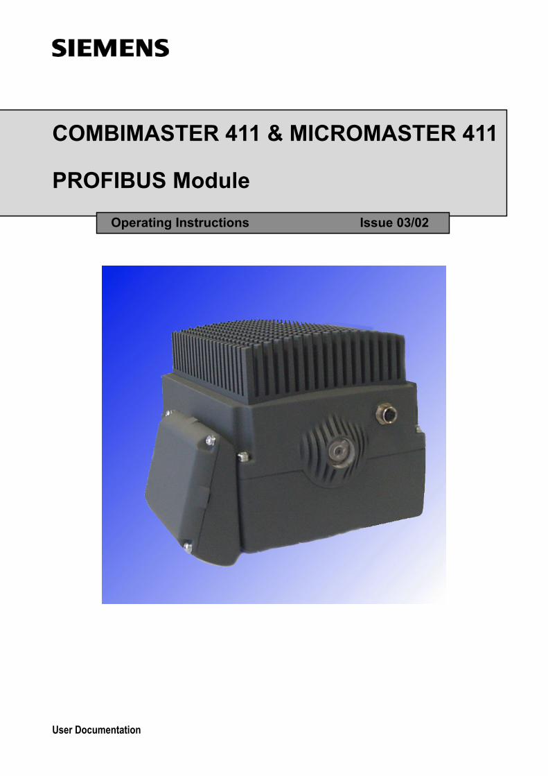
COMBIMASTER 411 & MICROMASTER 411 PROFIBUS Module Operating Instructions Issue 03/02 User Documentation
-
Upload
victor-farias-guerrero -
Category
Documents
-
view
9 -
download
1
Transcript of 411PROFIBUSENG
COMBIMASTER 411 & MICROMASTER 411
PROFIBUS Module
Operating Instructions Issue 03/02
User Documentation


COMBIMASTER 411 & MICROMASTER 411 PROFIBUS Module
Operating Instructions User Documentation
Valid for Issue 03/02
COMBIMASTER 411 March 2002 MICROMASTER 411
Issue 03/02
Description 1
General Definition
2
Communication 3
Connection 4
Configuration 5
Configuration of S7 PLC
6
Links to Master Systems
7
Diagnostics and Troubleshooting
8
Appendix 9
Glossary 10


Issue 03/02 DESCRIPTION
PROFIBUS Communication Module Operating instructions 6SE6400-5AV00-0BP0 5
Further information can be obtained from Internet website: http://www.siemens.de/micromaster Approved Siemens Quality for Software and Training is to DIN ISO 9001, Reg. No. 2160-01 The reproduction, transmission or use of this document, or its contents is not permitted unless authorized in writing. Offenders will be liable for damages. All rights including rights created by patent grant or registration of a utility model or design are reserved. © Siemens AG 2002. All Rights Reserved. MICROMASTER®, COMBIMASTER 411® and MICROMASTER 411® are registered trademarks of Siemens
Other functions not described in this document may be available. However, this fact shall not constitute an obligation to supply such functions with a new control, or when servicing. We have checked that the contents of this document correspond to the hardware and software described. There may be discrepancies nevertheless, and no guarantee can be given that they are completely identical. The information contained in this document is reviewed regularly and any necessary changes will be included in the next edition. We welcome suggestions for improvement. Siemens handbooks are printed on chlorine-free paper that has been produced from managed sustainable forests. No solvents have been used in the printing or binding process. Document subject to change without prior notice.
Order number: 6SE6400-5AK00-0BP0 Printed in the Federal Republic of Germany
Siemens-Aktiengesellschaft.

DESCRIPTION Issue 03/02
PROFIBUS Communication Module Operating instructions 6 6SE6400-5AV00-0BP0
Definitions, warnings
Qualified personnel For the purpose of this Instruction Manual and product labels, a "Qualified person" is someone who is familiar with the installation, mounting, start-up and operation of the equipment and the hazards involved. He or she must have the following qualifications: ��Trained and authorized to energize, de-energize, clear, ground and tag circuits
and equipment in accordance with established safety procedures. ��Trained in the proper care and use of protective equipment in accordance with
established safety procedures. ��Trained in rendering first aid. Safety guidelines This manual contains notices intended to ensure your personal safety, as well as to protect products and connected equipment against damage. Information relating to your personal safety is highlighted by a warning triangle. Warnings about property damage are displayed without a warning triangle. Depending on the degree of risk involved, safety-related information is presented in the following categories:
DANGER For the purpose of this documentation and the product warning labels, "Danger" indicates that death, severe personal injury or substantial damage to property will result if proper precautions are not taken.
WARNING For the purpose of this documentation and the product warning labels, "Warning" indicates that death, severe personal injury or substantial damage to property can result if proper precautions are not taken.
CAUTION With a warning triangle, "Caution" indicates that minor personal injury can result if proper precautions are not taken.
CAUTION Without a warning triangle, "Caution" indicates that material damage can result if proper precautions are not taken.
ATTENTION indicates that an undesirable effect or state can occur if attention is not paid to the advice given.
NOTE For the purpose of this documentation, "Note" indicates important information relating to the product or highlights part of the documentation for special attention.
!
!
!

Issue 03/02 DESCRIPTION
PROFIBUS Communication Module Operating instructions 6SE6400-5AV00-0BP0 7
User documentation WARNING Before installing and commissioning, please read these safety instructions and warnings carefully and all the warning labels attached to the equipment. Make sure that the warning labels are kept in a legible condition and replace missing or damaged labels.
NOTE Throughout this document MICROMASTER 4 refers to the fourth generation of MICROMASTER inverters. For the purpose of these Operating Instructions it should be taken to mean both COMBIMASTER 411 and MICROMASTER 411 unless specifically stated otherwise.
Proper use WARNING This equipment contains dangerous voltages and controls potentially dangerous rotating mechanical parts. Non-compliance with Warnings or failure to follow the instructions contained in this manual can result in loss of life, severe personal injury or serious damage to property. Only suitably qualified personnel should work on this equipment, and only after becoming familiar with all safety notices and maintenance procedures contained in this manual. The successful and safe operation of this equipment is dependent upon its proper handling, storage, installation, operation and maintenance. National safety regulations are also applicable.
NOTES ��This operating manual does not purport to cover all details or variations in
equipment, nor to provide for every possible contingency to be met in connection with installation, operation or maintenance.
��Should further information be desired or should particular problems arise which are not covered sufficiently for the Purchaser's purposes, the matter should be referred to the local Siemens Sales Office.
��The contents of this operating manual shall not become part of or modify any prior or existing agreement, commitment or relationship. The Sales Contract contains the entire obligations of Siemens. The warranty contained in the contract between the parties is the sole warranty of Siemens. Any statements contained herein do not create new warranties or modify the existing warranty.
NOTES ��This operating manual does not purport to cover all details or variations in
equipment, nor to provide for every possible contingency to be met in connection with installation, operation or maintenance.
��Should further information be desired or should particular problems arise which are not covered sufficiently for the Purchaser's purposes, the matter should be referred to the local Siemens Sales Office.
!
!

DESCRIPTION Issue 03/02
PROFIBUS Communication Module Operating instructions 8 6SE6400-5AV00-0BP0
Table of Contents
Definitions, warnings...................................................................... 6
1 Description of the MICROMASTER PROFIBUS Option module............................ 11 1.1 Technical data .............................................................................................. 12 1.2 Functionality.................................................................................................. 12
2 General Definition of PROFIBUS-DP ..................................................................... 13 2.1 Definition....................................................................................................... 13 2.2 RS-485 transmission system........................................................................ 13 2.2.1 General information about RS-485 transmission installation ....................... 13 2.2.2 Bus accessing mode .................................................................................... 14 2.3 Data exchange via PROFIBUS-DP .............................................................. 14 2.4 Standards, guidelines and other information................................................ 15
3 Communication with MICROMASTER 4 via PROFIBUS-DP................................. 17 3.1 Cyclical data of MICROMASTER 4 via PROFIBUS-DP............................... 17 3.1.1 Useful data structure as defined in PROFIDrive Profile 2.0 and 3.0 ............ 17 3.1.2 MICROMASTER 4 reaction time.................................................................. 21 3.2 Acyclic data transmission ............................................................................. 21 3.3 Control and status words.............................................................................. 22 3.4 PKW mechanism for processing parameters ............................................... 24
4 Connection to PROFIBUS-DP ................................................................................ 31 4.1 Installing the PROFIBUS-option module ...................................................... 31 4.1.1 List of Accessories........................................................................................ 31 4.1.2 Preparation of Inverter Terminal Housing .................................................... 31 4.1.3 PROFIBUS Option Module Installation......................................................... 34 4.1.4 Connection of an external 24 V voltage supply ............................................ 36 4.2 Connecting the bus cable using RS485 bus connectors.............................. 37 4.2.1 Maximum cable lengths................................................................................ 37 4.2.2 Comms Link Connector ................................................................................ 38 4.2.3 Connecting the Bus Cable............................................................................ 38 4.2.4 Bus terminator .............................................................................................. 39 4.2.5 Screening the Bus Cable / EMC precautions ............................................... 39
5 Configuration of the PROFIBUS ............................................................................. 42 5.1 PROFIBUS address ..................................................................................... 42 5.2 PROFIBUS Parameters................................................................................ 43
6 Configuration for S7 PLC........................................................................................ 49 6.1 Configuration using SIMATIC Manager........................................................ 49 6.2 Setting Parameters....................................................................................... 56 6.3 Confirmation of PROFIBUS Communications.............................................. 56 6.4 Controlling the Inverter with a PLC............................................................... 56

Issue 03/02 DESCRIPTION
PROFIBUS Communication Module Operating instructions 6SE6400-5AV00-0BP0 9
7 Links to PROFIBUS-DP Master Systems............................................................... 59 7.1 General ......................................................................................................... 59 7.2 Operation on SIMATIC S7............................................................................ 59 7.3 Exchanging data using internode communication function .......................... 61 7.4 SIMATIC HMI (Human-Machine Interface) .................................................. 63 7.5 Operation on external master systems......................................................... 65
8 Diagnostics and Troubleshooting ........................................................................... 67 8.1 Diagnostics using alarm number (Alarms and Faults).................................. 67 8.1.1 Alarms........................................................................................................... 67 8.1.2 Faults ............................................................................................................ 68 8.2 Diagnostics using diagnostic parameter....................................................... 68 8.2.1 Standard diagnostics .................................................................................... 68 8.2.2 Special diagnostics for start-up personnel ................................................... 70
9 Appendix ................................................................................................................. 71 9.1 Technical data .............................................................................................. 71 9.2 EMC information ........................................................................................... 71
10 Glossary.................................................................................................................. 72
List of Figures
Figure 1-1 PROFIBUS communication module......................................................................... 12
Figure 3-1 PROFIBUS-DP data channels ................................................................................. 18
Figure 3-2 Parameter process data object (PPO types)............................................................ 20
Figure 3-3 Parameter process data object (optional configuration) .......................................... 21
Figure 3-4 Structure of parameter area (PKW) ......................................................................... 25
Figure 4-1 Removing Inverter cover ................................................................................. 33
Figure 4-2 Removing the Filter and I/O Boards......................................................................... 33
Figure 4-3 Gland Plate or �knockout� Removal ......................................................................... 34
Figure 4-4 Fitting Gland Fixing Plates ................................................................................. 34
Figure 4-5 PROFIBUS Module Layout ................................................................................. 35
Figure 4-6 PROFIBUS Module Fixing to Inverter ...................................................................... 35
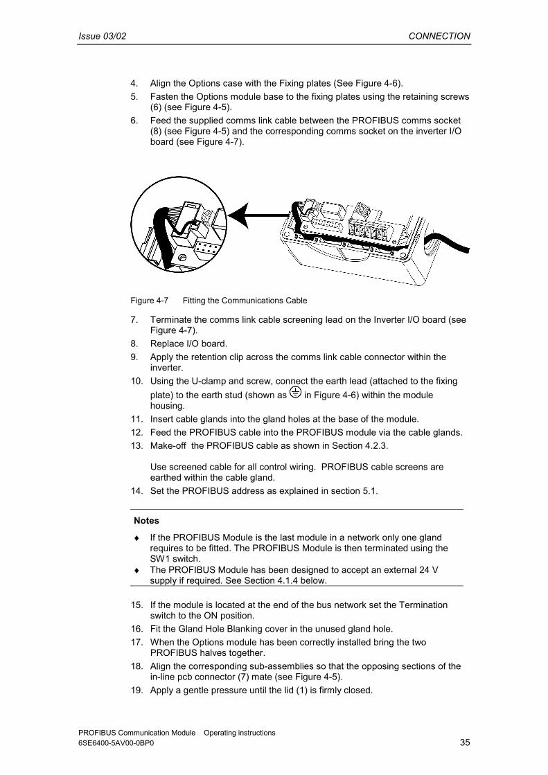
Figure 4-7 Fitting the Communications Cable ........................................................................... 36
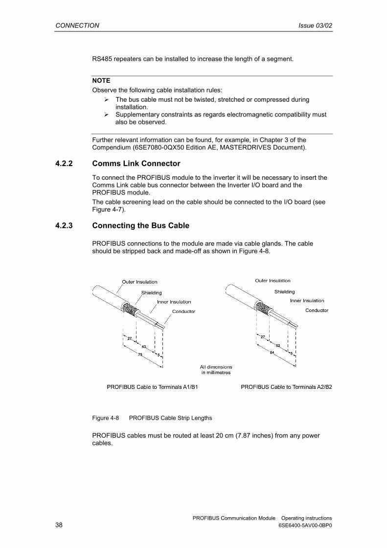
Figure 4-8 PROFIBUS Cable Strip Lengths .............................................................................. 39
Figure 4-9 Switch Positions for Bus Terminating Resistors....................................................... 40
Figure 4-10 Bus terminating network ................................................................................. 40
Figure 5-1 Jumpers and Termination switch ............................................................................. 43
Figure 6-1 New Project Screen ................................................................................. 49
Figure 6-2 Select Station Screen ................................................................................. 49
Figure 6-3 Hardware Configuration Window ............................................................................. 50

DESCRIPTION Issue 03/02
PROFIBUS Communication Module Operating instructions 10 6SE6400-5AV00-0BP0
Figure 6-4 Hardware Selection (SIMATIC 300)......................................................................... 50
Figure 6-5 Select Type of Racking ................................................................................. 51
Figure 6-6 Select Type of Power Supply ................................................................................. 51
Figure 6-7 Select type of CPU ................................................................................. 52
Figure 6-8 Select PROFIBUS Address Screen ......................................................................... 52
Figure 6-9 Selection of Baud Rate ................................................................................. 52
Figure 6-10 Selection Confirmation Screen................................................................................. 53
Figure 6-11 Hardware Configuration Screen............................................................................... 53
Figure 6-12 Selecting the Type of Inverter ................................................................................. 53
Figure 6-13 Dragging and Dropping the MICROMASTER 4 Profile............................................ 54
Figure 6-14 Selecting the PROFIBUS Address........................................................................... 54
Figure 6-15 Drag and Drop PKW and PZD into Hardware Table................................................ 55
Figure 6-16 Select I/O Module ................................................................................. 55
Figure 7-1 Principle of internode data communication on PROFIBUS-DP ............................... 61
Figure 7-2 Example of application of internode communication................................................ 63
List of Tables Table 3-1 Control Word Bit Assignments ................................................................................. 23
Table 3-2 Status Word Bit Assignments ................................................................................. 24
Table 3-3 Request identifier (master -> inverter)...................................................................... 26
Table 3-4 Response identifier (inverter -> master)................................................................... 26
Table 3-5 Fault numbers for �Cannot process request� response ........................................... 27
Table 4-1 List of Accessories ................................................................................. 32
Table 4-2 Torque Values ................................................................................. 37
Table 4-3 Terminal assignment of PROFIBUS terminals......................................................... 38
Table 4-4 Permissible cable length of one segment ................................................................ 38
Table 5-1 PROFIBUS Jumper Settings ................................................................................. 43
Table 5-2 Special Jumper Addresses ................................................................................. 44
Table 5-3 PROFIBUS Parameters ................................................................................. 44
Table 5-4 Parameters for flexible interconnection of process data .......................................... 45
Table 5-5 Communication Board Functions ............................................................................. 46
Table 8-1 Alarm Displays on Inverter ................................................................................. 67
Table 8-2 Fault Displays on Inverter ................................................................................. 68
Table 8-3 Standard Diagnostic Parameter ............................................................................... 68
Table 8-4 Parameter Accessing Errors ................................................................................. 69
Table 8-5 Special Diagnostics ................................................................................. 70
Table 9-1 Technical data ................................................................................. 71

Issue 03/02 DESCRIPTION
PROFIBUS Communication Module Operating instructions 6SE6400-5AV00-0BP0 11
1 Description of the MICROMASTER PROFIBUS Option module. The function of the PROFIBUS-DP communication board (PROFIBUS optional board) is to provide a communications link between inverters of the MICROMASTER 4 product range and a higher-level automated system. This PROFIBUS variant is specific to the MICROMASTER 411 and COMBIMASTER 411 Inverters.
Figure 1-1 PROFIBUS communication module

DESCRIPTION Issue 03/02
PROFIBUS Communication Module Operating instructions 12 6SE6400-5AV00-0BP0
1.1 Technical data PROFIBUS is contained within the cover of the Options module attached to the side of the inverter. The PROFIBUS unit is powered directly from the inverter and therefore needs no additional external supply during normal operation. Provision exists on PROFIBUS for the connection of an external control supply, which can be used to apply power to the Inverter control circuits. The board is connected to the PROFIBUS system via an 11 � way Communication Interface connector. All connections to this RS485 interface are short-circuit-proof and isolated.
1.2 Functionality ��Cyclical process data exchange (PZD) in accordance with PROFIDrive Profile,
version 2.0 or version 3.0 ��Parameter accessing:
Cyclical accessing of parameters (PKW) in accordance with PROFIDrive Profile version 2.0 or Acyclical accessing of parameters (data block 47) in accordance with PROFIDrive Profile version 3.0
��Acyclical accessing of parameters (data block 100/data block 47) for the purpose of exchanging parameter values with a SIMATIC S7 CPU (Drive ES SIMATIC function block package)
��Acyclical accessing of parameters for SIMATIC HMI or SIEMENS Drive STARTER tool.
��Support of PROFIBUS control commands SYNC and FREEZE for synchronized data transfer between the master and several slaves
��Internode communication for direct exchange of process data between PROFIBUS slaves (only in conjunction with SIMATIC S7 at the present time).

Issue 03/02 DEFINITION
PROFIBUS Communication Module Operating instructions 6SE6400-5AV00-0BP0 13
2 General Definition of PROFIBUS-DP
2.1 Definition PROFIBUS is an international, open field bus standard widely used in the fields of production and process automation. The bus is guaranteed brand-neutral and open by virtue of its compliance with international standards EN 50170 and IEC 61158. PROFIBUS-DP is a PROFIBUS communication profile optimized for high-speed, time-critical data transmission at field level using low-cost connections. PROFIBUS-DP is a suitable substitute for conventional, parallel 24 V signal transmission systems in manufacturing, as well as for analog 4 to 20 mA signal transmission systems in process automation. PROFIBUS is a multi-master system, in other words, it is a bus on which several automation, engineering or visualization systems can operate together with the associated distributed field devices. In the context of PROFIBUS, master and slave devices are defined as follows: ��Master devices control data traffic on the bus; they are also referred to as
�active� nodes. A master may transmit messages without prior receipt of an external request provided that it has bus access authorization (token). There are two classes of master: ♦ Class 1 master:
These are central automation stations (e.g. SIMATIC S5, S7 and SIMADYN D), which exchange information with slaves in predefined message cycles.
♦ Class 2 master: These are programming, configuring or operator control and monitoring systems that are used to configure or start up or monitor the plant in operation.
��Slave devices are field devices such as drives (MICROMASTER 4), I/O devices and valves. They never receive bus access authorization, i.e. they may only acknowledge received messages or return information to a master on request. Slave devices are also referred to as �passive� nodes.
2.2 RS-485 transmission system Criteria such as high transmission speed and simple, low-cost installation are of critical importance in the selection of the transmission system. The RS-485 requires a screened copper cable with twisted-pair wires. Transmission speeds can be selected within the 9.6 kbaud to 12 Mbaud range. It is set globally for all devices on the bus during system start-up.
2.2.1 General information about RS-485 transmission installation All devices are connected in a bus structure (line). Up to 32 nodes (master or slaves) can be interconnected within one segment. The bus is terminated by an active bus terminator at the beginning and end of each segment. To ensure fault-free operation, both bus terminators must have a voltage supply at all times. The
DEFINITION Issue 03/02
PROFIBUS Communication Module Operating instructions 14 6SE6400-5AV00-0BP0
bus terminators can normally be activated either in the devices themselves or on the bus termination connectors. To accommodate more than 32 nodes or increase the scope of the network, repeaters (cable amplifiers) can be installed to link the individual bus segments.
2.2.2 Bus accessing mode PROFIBUS operates according to the token passing principle, i.e. the active stations (masters) receive transmit authorization in a logical ring for a defined time window. Within this window, the master can communicate with other masters or exchange data with the relevant slaves in a subordinate master-slave process. PROFIBUS-DP primarily utilizes the master-slave process for this purpose; in most cases, it exchanges data with drives such as MICROMASTER 4 cyclically.
2.3 Data exchange via PROFIBUS-DP Data can be exchanged between the higher-level systems (e.g. SIMATIC, SIMADYN D, PC/PGs) and the drives very quickly via the PROFIBUS-DP. Drives are always accessed according to the master-slave principle. Drives are always slave nodes. Each slave can be identified by its unique address on the bus (MAC).
Issue 03/02 DEFINITION
PROFIBUS Communication Module Operating instructions 6SE6400-5AV00-0BP0 15
2.4 Standards, guidelines and other information All the standards and guidelines listed below can be obtained from the PROFIBUS User Organization (PNO), www.profibus.com. ��PROFIBUS
�Short Technical Description� September 1999 Order No. 4.001
��PROFIBUS Specification (FMS, DP, PA) All normative definitions in relation to the PROFIBUS specification according to EN 50170 Vol. 2.0 (version 1.0) Order No. 0.042 (English)
��PROFIBUS-DP Expansions includes acyclical communication functions with PROFIBUS-DP �Extensions to EN 50170� EN 50 170 Vol. 2 (version 2.0) Order No. 2.082 (English)
��PROFIBUS Technical Guideline �Installation Guidelines for PROFIBUS-DP/FMS� September 1998 Order No. 2.111
��PROFIBUS Guideline �Connections for PROFIBUS� February 2000 Version 1.0 Order No. 2.141
��PROFIBUS Guideline �Optical Transmission System for PROFIBUS� July 1999 (Draft) Version 2.0 Order No. 2.021
��PROFIDrive Profile Version 2.0: �Profile for Variable-Speed Drives� September 1997 PNO � PROFIBUS Profile � Order No. 3.071 (German) / 3.072 (English)
��PROFIDrive Profile Version 3.0: �PROFIDrive Profile Drives� September 2000 (Draft) PNO � PROFIBUS Profile � Order No: 3.172 (English)

DEFINITION Issue 03/02
PROFIBUS Communication Module Operating instructions 16 6SE6400-5AV00-0BP0

Issue 03/02 COMMUNICATION
PROFIBUS Communication Module Operating instructions 6SE6400-5AV00-0BP0 17
3 Communication with MICROMASTER 4 via PROFIBUS-DP The following illustration shows an overview of the PROFIBUS-DP communication functions implemented on MICROMASTER 411 and COMBIMASTER 411.
PROFIBUS communication board
MICROMASTER4
Automation(Class 1 master)
S7, S5 and others
Configuring(Class 2 master)
DriveES, STARTER
Operation(Class 2 master)
SIMATIC HMI
Acyclic channelsCyclic channels
Drive, ET200
Internode communication(slave)
Drive, ET200
PROFIBUS-DP
Figure 3-1 PROFIBUS-DP data channels
3.1 Cyclical data of MICROMASTER 4 via PROFIBUS-DP MICROMASTER 4 is controlled via the cyclical PROFIBUS-DP channel. This channel can be used to exchange parameters. The structure of useful data for the cyclical channel is defined in the PROFIDrive Profile, version 2.0, and referred to as the Parameter Process data Object (PPO). PROFIDrive Profile defines for the drives the useful data structure with which a master can access the drive slaves using the cyclical data communication method.
3.1.1 Useful data structure as defined in PROFIDrive Profile 2.0 and 3.0
Useful data structure according to PPOs The useful data structure for cyclical data traffic is divided into two areas, which can be transmitted in each telegram as follows: �� Process data area (PZD), i.e. control words and setpoints, or status
information and actual values �� Parameter area (PKW) for reading/writing parameter values, reading out
faults, or reading out information about the properties of a parameter such as, for example, min/max limits, etc.
With which PPO type (see next page) the inverter is addressed by the PROFIBUS-DP master can be defined in the configuration data for the master when the bus system is started up. Which type of PPO is selected depends on the function of the

COMMUNICATION Issue 03/02
PROFIBUS Communication Module Operating instructions 18 6SE6400-5AV00-0BP0
drive in the automation network. Process data is always transferred. It is processed as top priority in the shortest time slice in the drive. Process data is used to control the drive in the automation network, On/Off commands, setpoint inputs, etc. The parameter area enables the user to access all parameters stored in the inverter via the bus system. For example, to read out detailed diagnostic information, faults messages, etc. Telegrams for cyclic data transmission thus have the following basic structure:
Protocol frame Useful data Protocol frame
(header) Parameter (PKW)1 Process data (PZD) (trailer)
PPO
1 PKW: Parameter identifier value
Five types of Parameter Process data Object (PPO) are defined (see Figure 3.2) according to PROFIDrive Profile, version 2.0 and these contain: ��Useful data without parameter area, with two or six words of process data or ��Useful data with parameter area, with two, six or ten words of process data.

Issue 03/02 COMMUNICATION
PROFIBUS Communication Module Operating instructions 6SE6400-5AV00-0BP0 19
PKW PZD
PKE
IND
PWE
PZD1 STW1ZSW1
PZD2HSWHIW
PZD3
PZD4
PZD5
PZD6
PZD7
PZD8
PZD9
PZD10
1st word
2nd word
3rd word
4th word
1st word
2nd word
3rd word
4th word
5th word
6th word
7th word
8th word
9th word
10th word
PPO1
PPO2
PPO3
PPO4
PPO5
PKW: PZD: PKE: IND: PWE:
Parameter identifier value Process data Parameter identifier Index Parameter value
STW: ZSW: HSW: HIW:
Control word 1 Status word 1 Main setpoint Main actual value
Figure 3-2 Parameter process data object (PPO types)
Note: MICROMASTER 4 supports only PPO1 and PPO3 (shaded areas). The useful data structure has been subdivided into the PKW and PZD areas in order to satisfy different functional requirements of the communication system. Parameter data area (PKW) The PKW (parameter identifier value) telegram section can be used to monitor and/or change any parameter in the inverter. The request/response identifier mechanisms required to do this are described in Section 3.4 �PKW mechanism�. Process data area (PZD) Control words and setpoints (requests: Master → inverter) and status words and actual values (responses: Inverter → master) can be transmitted in the process data area. The transferred process data do not take effect until the bits used in the control words, setpoints, status words and actual values have been routed in the inverter as described in Section �Process data connections� of the reference manual.

COMMUNICATION Issue 03/02
PROFIBUS Communication Module Operating instructions 20 6SE6400-5AV00-0BP0
Extended configuration In addition to the PPO types, cyclical data can also be configured optionally. Up to four process data words, with a different number of setpoints and actual values if desired, can be configured on the MICROMASTER 4. The areas of consistency can be set flexibly. A parameter area (PKW) can be configured irrespective of the number of process data.
PKW PZD
PKE
IND
PWE PZD1 STW1ZSW1
PZD2HSWHIW
PZD3
PZD4
PZD5
PZD6
PZD7
PZD8
PZD9
PZD10
1st word
2nd word
3rd word
4th word
1st
word 2nd
word 3rd
word 4th
word 5th
word 6th
word 7th
word 8th
word 9th
word 10th word
Max.
Max.
PKW: PZD: PKE: IND: PWE:
Parameter identifier value Process data Parameter identifier Index Parameter value
STW: ZSW: HSW: HIW:
Control word 1 Status word 1 Main setpoint Main actual value
Figure 3-3 Parameter process data object (optional configuration)
Default assignment of PZD3/4 DP Master � MICROMASTER 4: PZD3: No default assignment PZD4: No default assignment PZD3 and PZD4 can be freely assigned and interconnected by means of BICO parameters. MICROMASTER 4 � DP Master: PZD3: No default assignment PZD4: Status word 2, r0053 Planning the extended configuration The GSD can be used to choose between the configurations shown in Fig. 3-3 (in addition to PPO types 1 and 3). An additional optional configuration is possible with Drive ES.
Issue 03/02 COMMUNICATION
PROFIBUS Communication Module Operating instructions 6SE6400-5AV00-0BP0 21
3.1.2 MICROMASTER 4 reaction time The reaction time of MICROMASTER 4 with respect to PZD is approximately 20 milliseconds. This represents the period of time between �setpoint arrives at DP slave� and �updated (and referencing) actual value is made available on PROFIBUS-DP�. The reaction time of the MICROMASTER 4 with respect to a parameter modification (PKW) is approximately 50 milliseconds.
3.2 Acyclic data transmission
Extended PROFIBUS-DP functions (DPV1)
The PROFIBUS-DP extensions DPV1 include the definition of an acyclic data exchange which can take place in parallel to cyclical data transmissions. Acyclic data transfer mode allows ��large quantities of useful data (up to 240 bytes) to be exchanged ��simultaneous accessing by other PROFIBUS masters
(class 2 master, e.g. start-up tool) ��omission of I/O address in the SIMATIC and reduction of bus cycle time
through relocation of PKW area from the cyclical to the acyclical transmission channel
Conversion of extended PROFIBUS-DP functionality
The different masters, or different modes of data exchange, are represented by appropriate channels in MICROMASTER 4: ��Cyclical data exchange with one class 1 master
Use of DATA-EXCHANGE and PPO types according to PROFIDrive Profile. ��Acyclical data exchange with the same class 1 master
Use of DPV1 functions READ and WRITE The content of the transferred data block corresponds in this case to the structure of the parameter area (PKW) as defined in the USS specification (with data block 100) or the structure of the acyclical parameter channel according to PROFIDrive Profile, version 3.0 (with data block 47).
��Acyclical data exchange using a SIEMENS start-up tool (class 2 master) The start-up tool can acyclically access parameter and process data in the inverter.
��Acyclical data exchange with a SIMATIC HMI (second class 2 master) The SIMATIC HMI can acyclically access parameters in the inverter.
��Instead of a SIEMENS start-up tool or SIMATIC HMI, an external master (class 2 master) as defined in the acyclical parameter channel according to PROFIDrive Profile version 3.0 (with data block 47) can access the inverter.

COMMUNICATION Issue 03/02
PROFIBUS Communication Module Operating instructions 22 6SE6400-5AV00-0BP0
3.3 Control and status words The control and status words comply with the specifications for PROFIDrive Profile, version 2.0 or 3.0, for �Closed-loop speed control mode�. Control word (bits 0-10 as per PROFIDrive Profile, bits 11-15 specific to MICROMASTER 4)
Table 3-1 Control Word Bit Assignments
Bit Value Meaning Remarks
0 1 ON Sets the inverter to the �Ready to run� state, direction of rotation must be defined via bit 11
0 OFF1 Shutdown, deceleration along RFG ramp, pulse disable when f<fmin
1 1 Operating condition - 0 OFF2 Instantaneous pulse disable, drive coasts to a standstill 2 1 Operating condition - 0 OFF3 Rapid stop: Shutdown at fastest possible acceleration rate 3 1 Enable operation Closed-loop control and inverter pulses are enabled 0 Disable operation Closed-loop control and inverter pulses are disabled 4 1 Operating condition - 0 Disable ramp-function
generator Output of RFG is set to 0 (fastest possible braking operation), inverter remains in the ON state
5 1 Enable RFG - 0 Stop RFG Setpoint currently supplied by the RFG is �frozen� 6 1 Enable setpoint Value selected at the RFG input is activated. 0 Disable setpoint Value selected at the RFG input is set to 0. 7 1 Acknowledge fault Fault is acknowledged with a positive edge, inverter then
switches to �starting lockout� state 0 No meaning 8 1 CW inching 0 9 1 CCW inching 0 10 1 Setpoints valid Master transfers valid setpoints 0 Setpoints invalid 11 1 Setpoint inverted Motor rotates CCW in response to positive setpoint 0 Setpoint is not inverted Motor rotates CW in response to positive setpoint 12 - - Not used 13 1 Motor potentiometer UP 0 14 1 Motor potentiometer DOWN 0 15 - - Not used
Warning The control words for MICROMASTER 4 and MICROMASTER 3 are different! !

Issue 03/02 COMMUNICATION
PROFIBUS Communication Module Operating instructions 6SE6400-5AV00-0BP0 23
Status word (bits 0-10 as per PROFIDrive Profile, bits 11-15 specific to MICROMASTER 4)
Table 3-2 Status Word Bit Assignments
Bit Value Meaning Remarks
0 1 Ready for ON Power supply switched on, electronics initialized, pulses disabled
0 Not ready for ON 1 1 Ready to run (see control word bit 0)
Inverter is switched on (ON command is applied), no fault is active, inverter can start when �Enable operation� command is issued.
0 Not ready to run Causes: No ON command, fault, OFF2 or OFF3 command, starting lockout
2 1 Operation enabled See control word, bit 3 0 Operation disabled 3 1 Fault is active Fault, see fault parameter r0947 etc.
Drive is faulty and thus inoperative, switches to starting lockout state after successful correction and acknowledgement of fault.
0 - 4 1 - 0 OFF2 command applied See control word, bit 1 5 1 - 0 OFF3 command applied See control word, bit 2 6 1 Starting lockout Drive can be restarted only by OFF1 followed by ON 0 No starting lockout 7 1 Alarm is active Alarm, see alarm parameter r2110.
Drive still in operation. 0 - 8 1 No setpoint/act.val.
deviation Setpoint/actual value deviation within tolerance range
0 Setpoint/act.val. deviation 9 1 Master control requested The master is being requested to accept status as master
control. 0 Local operation The master is not currently the master control. 10 1 F reached Inverter output frequency is higher or equal to the maximum
frequency 0 F not reached 11 1 0 Alarm: Motor at current limit 12 1 Signal can be used to control a holding brake. 0 Motor holding brake 13 1 Motor data indicate overload condition 0 Motor overload 14 1 CW rotation 0 CCW rotation 15 1 e.g. current or temperature 0 Inverter overload

COMMUNICATION Issue 03/02
PROFIBUS Communication Module Operating instructions 24 6SE6400-5AV00-0BP0
3.4 PKW mechanism for processing parameters Parameter area (PKW) Using the PKW mechanism you can process and monitor parameters (write/read) as described below: Precondition: PPO type 1 on MICROMASTER 4 in accordance with PROFIDrive Profile version 2.0 or use of acyclical channel in conjunction with data block 100 The parameter area includes at least 4 words.
Parameter identifier (PKE) 1st word
Bit no.: 15 12 11 10 0 AK 0 PNU
Parameter index (IND) 2nd word
Bit no.: 15 8 7 0 Structure and meaning are dependent on mode of data exchange used (see
following pages)
Parameter value (PWE)
Parameter value high (PWE1) 3rd word Parameter value low (PWE2) 4th word AK:
PNU: Request or response identifier
Parameter number
Figure 3-4 Structure of parameter area (PKW)
Parameter identifier (PKE), 1st word
The parameter identifier (PKE) is always a 16-bit value. Bits 0 to 10 (PNU) contain the number of the relevant parameter. Bit 11 is reserved. Bits 12 to 15 (AK) contain the request or the response identifier.
The meaning of the request identifier for request telegrams (master → inverter) is shown in
Table 3-3 Request identifier (master -> inverter). Request identifiers 11 to 14 are specific to MICROMASTER and not defined in the PROFIDrive Profile. The meaning of the response identifier for response telegrams (inverter → master) is shown in Table 3-4. The request identifier will determine which response identifiers are possible. If the response identifier is 7 (cannot process request), then one of the fault numbers listed in Table 3-5 will be stored in parameter value 2 (PWE2).

Issue 03/02 COMMUNICATION
PROFIBUS Communication Module Operating instructions 6SE6400-5AV00-0BP0 25
Table 3-3 Request identifier (master -> inverter)
Meaning Response identifierRequest identifier positive negative
0 No request 0 7 / 8 1 Request parameter value 1 / 2 ↑ 2 Modify parameter value (word) 1 3 Modify parameter value (double word) 2 4 Request descriptive element 1 3 6 Request parameter value (array) 1 4 / 5 7 Modify parameter value (array, word) 2 4 8 Modify parameter value (array, double word) 2 5 9 Request number of array elements 6
11 Modify parameter value (array, double word) and store in EEPROM 2
5
12 Modify parameter value (array, word) and store in EEPROM 2
4
13 Modify parameter value (double word) and store in EEPROM
2 ↓
14 Modify parameter value (word) and store in EEPROM 1 7 / 8
Table 3-4 Response identifier (inverter -> master)
Response identifier
Meaning
0 No response 1 Transfer parameter value (word) 2 Transfer parameter value (double word) 3 Transfer descriptive element 1 4 Transfer parameter value (array word) 2 5 Transfer parameter value (array double word) 2 6 Transfer number of array elements 7 Cannot process request (with error number) 8 No master control status for PKW interface
Notes
1 The desired element of the parameter description is specified in IND (2nd word) 2 The desired element of the indexed parameter is specified in IND (2nd word).

COMMUNICATION Issue 03/02
PROFIBUS Communication Module Operating instructions 26 6SE6400-5AV00-0BP0
Table 3-5 Fault numbers for �Cannot process request� response
No. Meaning
0 Illegal parameter number (PNU) Parameter does not exist 1 Parameter value cannot be modified Parameter is a read-only parameter 2 Minimum/maximum not reached/exceeded - 3 Faulty subindex - 4 No array Single parameter has been accessed with
array request and subindex > 0 5 Incorrect data type Mix-up between word and double word 6 Setting not allowed (resetting only) - 7 Descriptive element cannot be modified Description can never be modified with
MICROMASTER 4 11 No status as master control Modification request without status as master
control (see P0927) 12 Key word missing - 17 Request cannot be processed due to operating
state Current inverter status is not compatible with the received request
101 Parameter number currently deactivated Dependent on inverter status 102 Channel not wide enough Communication channel too small for
response 104 Illegal parameter value Parameter permits only certain values 106 Request not implemented After request identifier 5, 10, 15 200/ 201
Modified minimum/maximum not reached/exceeded
Minimum/maximum can be further limited in operation
204 Available access authorization does not cover modification of parameters
-

Issue 03/02 COMMUNICATION
PROFIBUS Communication Module Operating instructions 6SE6400-5AV00-0BP0 27
Parameter index (IND) 2nd word Important NOTE Assignments of index (IND) differ in the PPOs and on the acyclical channel (data block 100):
Structure of IND for cyclical communication via PPOs
PKE IND PWE1 PWE2 HIGH LOW
Array subindex MICROMASTER 4-specific 15 8 7 0
Subindex 0- 255 Bit 7=PARA PAGE SEL The array subindex (referred to simply as �subindex� in the PROFIDrive Profile) is an 8-bit value which is transferred in the high-order byte (bits 8 to 15) of the parameter index (IND) when data are transferred cyclically via PPOs. The low-order byte (bits 0 to 7) is not defined in PROFIDrive Profile version 2.0. The low-order byte of the parameter index is used on MICROMASTER 4 to be able to address additional parameters with a number of >1999.
Structure of IND for acyclical communication
PKE IND PWE1 PWE2 HIGH LOW
MICROMASTER 4-specific
Array subindex
15 8 7 0 Bit 15 = PARA PAGE SEL Subindex 0- 255
The array subindex is an 8-bit value which is always transferred in the low-order byte (bits 0 to 7) of the parameter index (IND) in acyclical data exchange mode. The Parameter Page Selection task for additional parameters is performed in this case by the high-order byte (bits 8 to 15) of the parameter index. This structure conforms to the USS specification.

COMMUNICATION Issue 03/02
PROFIBUS Communication Module Operating instructions 28 6SE6400-5AV00-0BP0
Function of the subindex in IND
Subindex = 0 .. 254 If the subindex is transferred with values between 0 and 254 in a request, the relevant parameter index is transferred in the case of an indexed parameter. For the meaning of the individual indices of a parameter, please refer to the �Parameter List� in the inverter operating instructions. In the case of a descriptive element, the number of the required element is transferred. The meaning of descriptive elements can be found in the PROFIDrive Profile, version 2.0.
Subindex = 255 A value of 255 for the array subindex is a MICROMASTER 4-specific, special function. If the array index is transferred with 255, all the indices of an indexed parameter are transmitted simultaneously in one data block. The function is meaningful only for acyclical data exchange mode. The structure of the transferred data block complies with the USS specification. The maximum data block size is 206 bytes. Function of PARA PAGE SEL The bit for parameter page selection functions as follows: If it is set to 1, an offset of 2000 is applied in MICROMASTER 4 to the parameter number (PNU) transferred in the PKW request before it is passed on.
Parameter name (acc. To Parameter List)
Corresponding mode of parameter addressing via PROFIBUS
PNU [decimal]
PNU [Hex.]
Bit 15: PARA PAGE SEL
P0000 � P1999 0 � 1999 0 � 7CF = 0 P2000 � P3999 0 � 1999 0 � 7CF = 1
Parameter value (PWE) 3rd and 4th word
The parameter value (PWE) is always transmitted as a double word (32-bit). Only one parameter value at a time can be transferred in a PPO telegram. A 32-bit parameter value comprises PWE1 (high-order word, 3rd word) and PWE2 (low-order word, 4th word). A 16-bit parameter value is transferred in PWE2 (low-order word, 4th word). PWE1 (high-order word, 3rd word) must be set to 0 on the PROFIBUS-DP master in this case.

Issue 03/02 COMMUNICATION
PROFIBUS Communication Module Operating instructions 6SE6400-5AV00-0BP0 29
Rules for processing requests/responses
��A request or a response can only ever refer to one parameter. ��The master must repeat a request continuously until it has received the
appropriate response. ��The master detects the response to a request it has sent by
♦ evaluating the response identifier, ♦ evaluating the parameter number PNU, ♦ evaluating the parameter index IND if necessary, or ♦ evaluating the parameter value PWE if necessary.
��The complete request must be sent in one telegram. Request telegrams cannot be split. The same applies to responses.
��In the case of response telegrams which contain parameter values, the drive always returns the momentary parameter value when repeating response telegrams.
��If no information needs to be fetched from the PKW interface in cyclical operation (only PZD data are relevant), then the �No request� request telegram must be issued.

COMMUNICATION Issue 03/02
PROFIBUS Communication Module Operating instructions 30 6SE6400-5AV00-0BP0

Issue 03/02 CONNECTION
PROFIBUS Communication Module Operating instructions 6SE6400-5AV00-0BP0 31
4 Connection to PROFIBUS-DP
4.1 Installing the PROFIBUS-option module
!
!
Warning
♦ Make sure that the MICROMASTER 411/COMBIMASTER 411 inverter is isolated from the electrical supply before you install or remove the PROFIBUS-option module.
Cautions
♦ Do not knock out cable gland blanking plates unless inverter �electronics� (Filter & I/O boards) have been removed!
♦ The inverter and PROFIBUS module electronics contain static sensitive
devices therefore precautions must be taken against electrostatic discharge (ESD) when handling the separated inverter assembly. These include not touching the internal surfaces of the inverter and ensuring that personnel are earthed while handling the unit. The terminal housing, including Filter and I/O modules, contain no sensitive components and therefore no special handling precautions are required when separated.
4.1.1 List of Accessories A list of the accessories provided with the PROFIBUS Communications Module is given in Table 4-1 below.
Table 4-1 List of Accessories
1. 1-off Gland Hole Blanking Cover
6. 4-off M4 x 20 Screws
2. 2-off M16 Cable Gland 7. 1-off Communication Link Cable
3. 2-off U-clamp (for earth connection)
8. 1-off Comms Link Connector Retention Clip.
4. 1-off Option Gland Fixing Plate
9. 8-off Jumpers
5. 2-off O-ring Sealing Gasket
10. 1-off Option Gland fixing Plate with Earth Lead
11. 6-off M4 x 10 Screws
4.1.2 Preparation of Inverter Terminal Housing To mount the PROFIBUS-DP options module on the inverter body the following procedure should be performed:
1. If the Inverter has already been fitted unscrew the four crosshead captive screws (1) on the inverter cover (as shown Figure 4-1).

CONNECTION Issue 03/02
PROFIBUS Communication Module Operating instructions 32 6SE6400-5AV00-0BP0
Figure 4-1 Removing Inverter cover
2. Remove inverter top cover.
3. Remove the I/O Board (2) (as shown in Figure 4-2).
4. Remove the Filter Board (1) (as shown in Figure 4-2).
Figure 4-2 Removing the Filter and I/O Boards
5. Using a hammer and a flat-head screwdriver (as shown in Figure 4-3) strike the gland plate or �knockout�.
Warning The PROFIBUS module MUST be mounted on the inverter on the opposite side to the Rating Label.
!

Issue 03/02 CONNECTION
PROFIBUS Communication Module Operating instructions 6SE6400-5AV00-0BP0 33
Figure 4-3 Gland Plate or �knockout� Removal
6. Remove any sharp edges/burrs/swarf in the knockouts and terminal housing.
7. Slide the fixing plates into the slots provided immediately behind the gland access holes (as shown in Figure 4-4).
Figure 4-4 Fitting Gland Fixing Plates
8. Ensure that the earth lead is fed back through the fixing plate. 9. Feed the earth lead into the PROFIBUS Module housing. 10. Replace the Filter Module.

CONNECTION Issue 03/02
PROFIBUS Communication Module Operating instructions 34 6SE6400-5AV00-0BP0
4.1.3 PROFIBUS Option Module Installation
Figure 4-5 PROFIBUS Module Layout
With the fixing plates inserted it is now possible to mount the PROFIBUS module by carrying out the following procedure:
1. Unscrew the four cover retaining screws (3) (see Figure 4-5). 2. Carefully detach the module cover from the base (2). 3. Insert the ̀O ́ ring sealing gaskets (see Figure 4-6).
Gaskets should be placed in position adhesive-side to the inverter.
Figure 4-6 PROFIBUS Module Fixing to Inverter
Issue 03/02 CONNECTION
PROFIBUS Communication Module Operating instructions 6SE6400-5AV00-0BP0 35
4. Align the Options case with the Fixing plates (See Figure 4-6). 5. Fasten the Options module base to the fixing plates using the retaining screws
(6) (see Figure 4-5). 6. Feed the supplied comms link cable between the PROFIBUS comms socket
(8) (see Figure 4-5) and the corresponding comms socket on the inverter I/O board (see Figure 4-7).
Figure 4-7 Fitting the Communications Cable
7. Terminate the comms link cable screening lead on the Inverter I/O board (see Figure 4-7).
8. Replace I/O board. 9. Apply the retention clip across the comms link cable connector within the
inverter. 10. Using the U-clamp and screw, connect the earth lead (attached to the fixing
plate) to the earth stud (shown as in Figure 4-6) within the module housing.
11. Insert cable glands into the gland holes at the base of the module. 12. Feed the PROFIBUS cable into the PROFIBUS module via the cable glands. 13. Make-off the PROFIBUS cable as shown in Section 4.2.3.
Use screened cable for all control wiring. PROFIBUS cable screens are earthed within the cable gland.
14. Set the PROFIBUS address as explained in section 5.1.
Notes
♦ If the PROFIBUS Module is the last module in a network only one gland requires to be fitted. The PROFIBUS Module is then terminated using the SW1 switch.
♦ The PROFIBUS Module has been designed to accept an external 24 V supply if required. See Section 4.1.4 below.
15. If the module is located at the end of the bus network set the Termination
switch to the ON position. 16. Fit the Gland Hole Blanking cover in the unused gland hole. 17. When the Options module has been correctly installed bring the two
PROFIBUS halves together. 18. Align the corresponding sub-assemblies so that the opposing sections of the
in-line pcb connector (7) mate (see Figure 4-5). 19. Apply a gentle pressure until the lid (1) is firmly closed.

CONNECTION Issue 03/02
PROFIBUS Communication Module Operating instructions 36 6SE6400-5AV00-0BP0
20. Secure the lid via retaining screws (3) at each corner.
Table 4-2 Torque Values
Torque Value Thread Size
Retention Screw Nm [lbf.in]
M3 Filter and I/O board screw. 0.8 7.0
M4 CSB Inverter Cover Screw.
CSB & C Module Fixing.
Cover Retaining Screw.
1.2 10.6
M5 CSC Inverter Cover screws. 2.4 21.3
4.1.4 Connection of an external 24 V voltage supply
The PROFIBUS module has been designed to allow an external 24 V Power Supply to be provided to the Profibus Module.
If this arrangement is required, it is necessary to make use of a �Hybrid� Cable which provides both communications and power supply cable cores, which is fed into the PROFIBUS module through the module gland holes.
Recommended cable type :
PROFIBUS Cable (hybrid) : Siemens Type : 6ES7 194 -1LY10-0AA0-Z
Due to the larger cross section of this hybrid cable to standard PROFIBUS Cable, it is recommended to use the following cable gland arrangement (not included with PROFIBUS Module) :
a. Cable Gland M20 x 1.5 (Suggested Type : Lapp Group : Part Nr : 53112630).
b. Gland adapter ring : M20x1.5 to M16x1.5 (Suggested type : Malux : Part nr. : CA-740274)
This arrangement is required for each cable gland hole. A +10 V to +24 V DC external power supply can be connected via the 11-way terminal block, see Section 4.2.

Issue 03/02 CONNECTION
PROFIBUS Communication Module Operating instructions 6SE6400-5AV00-0BP0 37
4.2 Connecting the bus cable using RS485 bus connectors Warning An inverter can be switched on unintentionally if the serial bus installation is not performed correctly. The bus must be started up by personnel who are qualified and trained in installing systems of this type. Terminal assignment of PROFIBUS terminals The Options Interface board has an 11 way terminal block to provide for connections on to the PROFIBUS system. Terminals are short-circuit-proof and isolated.
Table 4-3 Terminal assignment of PROFIBUS terminals
Terminal Designation Meaning Range
1 A1 Receive/Send data P RS-485 2 B1 Receive/Send data N RS-485 3 0Vin Low voltage terminal 0 V 4 24Vin Supply voltage positive 24 V ± 10 % 5 0V Isolated Low voltage terminal 0 V 6 +5V Isolated Supply voltage positive 5 V ± 10 % 7 RTS RTS Control signal TTL 8 0Vin Low voltage terminal 0 V 9 24Vin Supply voltage positive 24 V ± 10 %
10 A2 Receive/Send data P RS-485 11 B2 Receive/Send data N RS-485
4.2.1 Maximum cable lengths RS-485-compliant transmission is the transmission mode used most frequently on PROFIBUS-DP. This requires a twisted, screened copper cable with one conductor pair. A total of 124 devices can be connected to one PROFIBUS line. Up to 32 devices can be interconnected in a linear structure within one bus segment. If the configuration includes more than 32 nodes, repeaters (cable amplifiers) must be installed to link the individual bus segments. Maximum cable lengths are dependent on the baud rate (transmission speed). Cable lengths specified in the table below can be guaranteed only with approved PROFIBUS bus cables (e.g. Siemens PROFIBUS cable available under order number (MLFB) 6XV1830-0EH10).
Table 4-4 Permissible cable length of one segment
Baud rate Max. cable lengths of one segment [m]
9.6 to 187.5 kbaud 1000 500 kbaud 400 1.5 Mbaud 200 3 to 12 Mbaud 100
!
CONNECTION Issue 03/02
PROFIBUS Communication Module Operating instructions 38 6SE6400-5AV00-0BP0
RS485 repeaters can be installed to increase the length of a segment.
NOTE Observe the following cable installation rules:
��The bus cable must not be twisted, stretched or compressed during installation.
��Supplementary constraints as regards electromagnetic compatibility must also be observed.
Further relevant information can be found, for example, in Chapter 3 of the Compendium (6SE7080-0QX50 Edition AE, MASTERDRIVES Document).
4.2.2 Comms Link Connector To connect the PROFIBUS module to the inverter it will be necessary to insert the Comms Link cable bus connector between the Inverter I/O board and the PROFIBUS module. The cable screening lead on the cable should be connected to the I/O board (see Figure 4-7).
4.2.3 Connecting the Bus Cable
PROFIBUS connections to the module are made via cable glands. The cable should be stripped back and made-off as shown in Figure 4-8.
Figure 4-8 PROFIBUS Cable Strip Lengths
PROFIBUS cables must be routed at least 20 cm (7.87 inches) from any power cables.

Issue 03/02 CONNECTION
PROFIBUS Communication Module Operating instructions 6SE6400-5AV00-0BP0 39
4.2.4 Bus terminator For interference-free operation of PROFIBUS-DP, the bus cable must be terminated at both ends with bus terminating resistors. For the correct operation of a PROFIBUS network, the first and last PROFIBUS nodes of the network must be terminated. Correct termination is achieved by setting the Terminator Switch to the �ON� position marked on the Options Interface PCB as shown in Figure 4-9.
Figure 4-9 Switch Positions for Bus Terminating Resistors
If these bus terminators are not used, the user must ensure that a bus terminating network is installed on the first and last bus nodes as shown in Figure 4-10.
Figure 4-10 Bus terminating network
WARNING All stations on which a terminating resistor is activated must be supplied with power at all times, otherwise incorrect termination will result in possible communications errors.
4.2.5 Screening the Bus Cable / EMC precautions The following EMC-related precautions must be taken to ensure interference-free PROFIBUS-DP operation, particularly in RS-485 data exchange mode: Screening The screen of the PROFIBUS cable must be made-off within the cable gland.
!

CONNECTION Issue 03/02
PROFIBUS Communication Module Operating instructions 40 6SE6400-5AV00-0BP0
! Caution
Crossovers between bus and power cables must be laid at an angle of 90°. Equipotential bonding Differences in potential (e.g. due to different mains supplies) between the inverters and the PROFIBUS-DP master must be avoided. ��Recommended equipotential bonding cables:
♦ 16 mm2 Cu for equipotential bonding cables up to 200 m long ♦ 25 mm2 Cu for equipotential bonding cables of over 200 m long
��Equipotential bonding cables must be routed as close as possible to signal leads, i.e. that the area between the bonding conductor and signal lead is as small as possible.
��Equipotential bonding cables must be contacted in a 360° connection with the earth electrode/PE conductor.

Issue 03/02 CONFIGURATION
PROFIBUS Communication Module Operating instructions 6SE6400-5AV00-0BP0 41
CONFIGURATION Issue 03/02
PROFIBUS Communication Module Operating instructions 42 6SE6400-5AV00-0BP0
5 Configuration of the PROFIBUS WARNING Disconnect the inverter supply when installing the PROFIBUS Module.
NOTE Before the inverter (with PROFIBUS module connected) is switched on, either a Basic Operator Panel (BOP) or �Advanced Operator Panel� (AOP) should be inserted into the MICROMASTER 411 communications socket.
5.1 PROFIBUS address A minimum requirement for configuring the PROFIBUS module is to establish the PROFIBUS address setting within the network. There are two methods of setting the PROFIBUS address; these are as follows: ��via jumpers on the module interface board ��via parameter P0918.
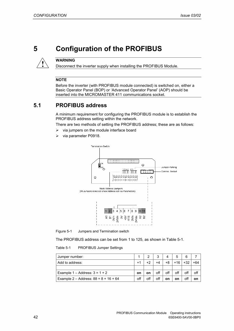
Figure 5-1 Jumpers and Termination switch
The PROFIBUS address can be set from 1 to 125, as shown in Table 5-1.
Table 5-1 PROFIBUS Jumper Settings
Jumper number: 1 2 3 4 5 6 7 Add to address: +1 +2 +4 +8 +16 +32 +64 Example 1 � Address: 3 = 1 + 2 on on off off off off off Example 2 � Address: 88 = 8 + 16 + 64 off off off on on off on
!

Issue 03/02 CONFIGURATION
PROFIBUS Communication Module Operating instructions 6SE6400-5AV00-0BP0 43
Some �addresses� have a special meaning:
Table 5-2 Special Jumper Addresses
Address Meaning
0 PROFIBUS address is determined by P0918 1..125 Valid PROFIBUS address 126, 127 Reserved PROFIBUS address
Important NOTE The inverter power supply must be switched off before any jumper settings are changed. The changes to jumper positions do not take effect until the PROFIBUS has been power cycled.
5.2 PROFIBUS Parameters The parameters shown in Table 5-3 must be set to correctly configure the PROFIBUS Module:
Table 5-3 PROFIBUS Parameters
Parameter Content
P0918 PROFIBUS address P0719 Process data master control P0700 Fast selection command source P1000 Fast selection frequency setpoint r2050 (Read-only) Process data setpoint source (BICO) P2051 Process data actual values (BICO) P2041 Communication board functions P2040 Process data telegram failure time P0927 Modification source for parameters r2054 (Read-only) Communication board diagnostics (see Section 8.2)
P0918 � PROFIBUS address If address 0 is set on the option interface board (default setting), then the PROFIBUS address can be changed using P0918. Valid settings are 1 to 125 (default = 3). Once a valid PROFIBUS address has been set on the jumpers, P0918 can no longer be changed. In this case, the parameter displays the jumper set PROFIBUS address. The �Reset inverter parameters to factory setting� function also resets the PROFIBUS address to 3 if it has been set originally via P0918.

CONFIGURATION Issue 03/02
PROFIBUS Communication Module Operating instructions 44 6SE6400-5AV00-0BP0
P0719 � Process Data Master Control For simple applications, P0719 can be set to 66 to select the setpoint source. Control Word 1 and the Master Setpoint are then accepted by the PROFIBUS optional board. Status Word 1 and the actual main value are output via the PROFIBUS optional board regardless of the setting in P0719. P0719 has priority over P0700 and P1000. P0700 and P1000 � Fast Selection The control word and setpoint sources can be selected quickly in P0700 (select command source) and P1000 (select frequency setpoint) respectively. P0719 must be set to 0 when BICO technology is used with P700 and P1000. r2050 and P2051 � BICO Much greater flexibility is afforded by the interconnection of process data using binectors/connectors, see description �Use of binectors and connectors� in the reference manual. Detailed connection of setpoints and actual values to and from the PROFIBUS optional board is parameterized in r2050 and P2051. The Table 5-4 shows the parameters specific to the PROFIBUS optional board relating to the connection of process data:
Table 5-4 Parameters for flexible interconnection of process data
Telegram: PZD1 STW/ZSW
PZD2 HSW/HIW
PZD3 PZD4
Link values for setpoints master → inverter
r2050.00 r2050.01 r2050.02 r2050.03
Link parameters for actual values inverter → master
P2051.00 P2051.01 P2051.02 P2051.03
PZD: Process data STW: Control word ZSW: Status word
HSW: Main setpoint HIW: Main actual value
NOTE r2050 also acts as a display parameter via which the setpoints received by the PROFIBUS optional board can be checked. P2041 � Communication Board Functions A number of advanced property settings for the PROFIBUS optional board can be made in the indexed parameter P204�. However, for most applications the defaults settings are adequate (value = 0). Table 5-5 on page 45 shows the property setting options.

Issue 03/02 CONFIGURATION
PROFIBUS Communication Module Operating instructions 6SE6400-5AV00-0BP0 45
Table 5-5 Communication Board Functions
Parameter Meaning Value range P2041.00 PPO type is specified by slave:
Some (rare!) PROFIBUS masters require a configuration specified by the slave. This option can be programmed in this parameter.
0: PPO1 1: PPO1 3: PPO3
P2041.01 OP parameter in EEPROM: Modifications to parameter settings via SIMATIC HMI are stored permanently in the EEPROM or as volatile data in the RAM.
0: Permanent (EEPROM) 1: Volatile (RAM)
P2041.02 Internode communication failure: Reaction of communication board (as subscriber) after failure of a publisher
0: Generate alarm A704 and abort setpoint transmission to inverter (may activate fault 70) 1: Generate alarm A704 only
P2041.03 Select displayed diagnostics screen. 0: Standard diagnostics >0: Special diagnostics (for SIEMENS internal use only)
Process data monitoring Two parameters determine how process data is monitored: ��Threshold monitoring on the PROFIBUS optional board (standard slave
function according to PROFIBUS) ��Monitoring of the telegram failure time in the inverter with parameter �P2040� The threshold monitoring function on the PROFIBUS optional board is normally activated. It can be deactivated via the PROFIBUS master configuring tool. NOTE The threshold monitoring function should not be deactivated! P2040 � Telegram Failure Time Parameter P2040 is set to determine whether setpoint transmission via PROFIBUS should be monitored by the inverter. ��P2040 = 0 means: No monitoring ��P2040 > 0 means: The value of �P2040� is the telegram failure time in
milliseconds. (The default setting of the parameter is a value of >0!)
Fault 0070 is activated if no new setpoints are received by the PROFIBUS optional board within the telegram failure period. Important NOTE Shutdown on faults only take place if both monitoring functions are activated! When the PROFIBUS optional board is in operation, P2040 should also be set to a value of > 0. The process data monitoring function is thus activated/deactivated solely via the PROFIBUS threshold monitor. Monitoring time then corresponds to the threshold monitoring time setting + the setting in P2040.
CONFIGURATION Issue 03/02
PROFIBUS Communication Module Operating instructions 46 6SE6400-5AV00-0BP0
NOTE Process data whose complete control word (PZD1) is set to zero are not transferred from the PROFIBUS Module to the inverter. Result: Alarm A703 and possibly fault 70. P0927 � Modification Source for Parameters This parameter can be set to define the sources of parameter modifications. Bit 0 PROFIBUS-DP 0: No
1: Yes Bit 1 BOP 0: No
1: Yes Bit 2 PC-inverter assembly set
(USS on the BOP interface) 0: No 1: Yes
Bit 3 Local RS-485 interface (terminal 14/15 and USS)
0: No 1: Yes
The default setting for all bits is 1, i.e. parameters can be modified from all sources.

Issue 03/02 CONFIGURATION
PROFIBUS Communication Module Operating instructions 6SE6400-5AV00-0BP0 47


Issue 03/02 CONFIGURATION FOR S7 PLC
PROFIBUS Communication Module Operating instructions 6SE6400-5AV00-0BP0 49
6 Configuration for S7 PLC The following section describes how to configure the PROFIBUS module to work correctly with a SIMATIC S7 Programmable Logic Controller (PLC). The procedure that follows will use the Step 7 software to configure the PROFIBUS module and the COMBIMASTER 411/MICROMASTER 411. NOTE If your version of the Step 7 software does not support MICROMASTER 4, the installation of the latest GSD file is required before the configuration procedures can be performed. The GSD file is located on the PROFIBUS Documentation CD-ROM and can also be downloaded from the Siemens Standard Drives Internet.
6.1 Configuration using SIMATIC Manager 1. Start SIMATIC Manager. 2. From the File Menu, select New Project (see Figure 6-1).
Figure 6-1 New Project Screen
3. Enter an appropriate Project Name. 4. The user is then presented with the Project Screen. 5. From the Insert Menu, select Station (see Figure 6-2).
Figure 6-2 Select Station Screen
CONFIGURATION FOR S7 PLC Issue 03/02
PROFIBUS Communication Module Operating instructions 50 6SE6400-5AV00-0BP0
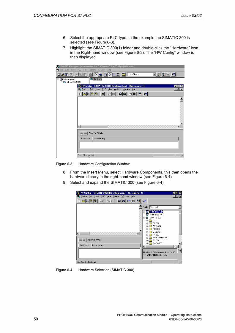
6. Select the appropriate PLC type. In the example the SIMATIC 300 is selected (see Figure 6-3).
7. Highlight the SIMATIC 300(1) folder and double-click the �Hardware� icon in the Right-hand window (see Figure 6-3). The �HW Config� window is then displayed.
Figure 6-3 Hardware Configuration Window
8. From the Insert Menu, select Hardware Components, this then opens the hardware library in the right-hand window (see Figure 6-4).
9. Select and expand the SIMATIC 300 (see Figure 6-4).
Figure 6-4 Hardware Selection (SIMATIC 300)

Issue 03/02 CONFIGURATION FOR S7 PLC
PROFIBUS Communication Module Operating instructions 6SE6400-5AV00-0BP0 51
10. Select the type of racking by dragging and dropping the appropriate rail type from the right-hand window into the top left-hand window (see Figure 6-5).
11. Select the type of power supply by dragging and dropping the PSU type from the right-hand window into slot 1 of the table in the left-hand window (see Figure 6-6).
12. Select the type of CPU (see Figure 6-7 on page 52). The CPU occupies two slots of the Hardware configuration table.
Figure 6-5 Select Type of Racking
Figure 6-6 Select Type of Power Supply
13. Once the CPU is selected the user will be prompted to select the type of PROFIBUS (see Figure 6-8).

CONFIGURATION FOR S7 PLC Issue 03/02
PROFIBUS Communication Module Operating instructions 52 6SE6400-5AV00-0BP0
Figure 6-7 Select type of CPU
Figure 6-8 Select PROFIBUS Address Screen
14. Select the �New� option on the PROFIBUS properties screen. 15. Click the �Network Settings� tab and select the appropriate Baud rate (see
Figure 6-9).
Figure 6-9 Selection of Baud Rate
16. Select the correct PROFIBUS profile (normally DP) then click OK. 17. The Selection Confirmation Screen is displayed (see Figure 6-10 on page
53). 18. Click OK to accept the selected Baud rate and Profile.

Issue 03/02 CONFIGURATION FOR S7 PLC
PROFIBUS Communication Module Operating instructions 6SE6400-5AV00-0BP0 53
Figure 6-10 Selection Confirmation Screen
19. The Hardware Configuration Screen is displayed with the PROFIBUS configuration that has been selected (see Figure 6-11).
Figure 6-11 Hardware Configuration Screen
20. In the right-hand window, select MICROMASTER 4 from the PROFIBUS DP top level folder. (see Figure 6-12). This folder could be in either �SIMOVERT� or �Additional Field Devices) depending upon how the GSD file has been installed.
Figure 6-12 Selecting the Type of Inverter

CONFIGURATION FOR S7 PLC Issue 03/02
PROFIBUS Communication Module Operating instructions 54 6SE6400-5AV00-0BP0
21. Select MICROMASTER 4 and drag and drop it onto the PROFIBUS in the Hardware Diagram (see Figure 6-13 below).
Figure 6-13 Dragging and Dropping the MICROMASTER 4 Profile
A window for selecting the bus address now appears (see Figure 6-14).
Figure 6-14 Selecting the PROFIBUS Address
22. Select the appropriate bus address from the scroll-down list. 23. Choose the appropriate data format; PPO3 or PPO1, or one of the custom
options for MICROMASTER 4. PPO3 allows two process data words (PZD) corresponding to the control word and frequency reference (outputs from the PLC to the inverter) and the status word and actual frequency (inputs to the PLC from the inverter). PPO1 has four additional data words that allow the inverter parameters to be read and changed. Other formats allow additional PZD data to be sent and received, for example, if you want to be able to read the motor current directly. For non PPO formats word consistency is recommended. If whole consistency is required the PLC program has to use the standard function blocks SFC14/SFC15 to read data from the inverter. The S7 commands L PIW, T PQW etc, are only allowed with word consistency.

Issue 03/02 CONFIGURATION FOR S7 PLC
PROFIBUS Communication Module Operating instructions 6SE6400-5AV00-0BP0 55
24. Drag and drop the selected PKW and PZD onto the Module/DP ID Column (Slot 0) in the lower left-hand window (see Figure 6-15).
Figure 6-15 Drag and Drop PKW and PZD into Hardware Table
25. Select the type of I/O module (see Figure 6-16).
Figure 6-16 Select I/O Module
26. The Bus configuration is now complete. Step 7 automatically assigns addresses for the PKW and PZD data in the peripheral address area (in the example, from byte 256 upwards). If required you can change the automatic assignment. In the example, the 4 PKW words are in bytes 256 to 263 and the 2 PZD words are in bytes 264 to 267. In Step 7, the control word and frequency reference can be represented as PQD 264 (peripheral output double word) and the status word and actual frequency as PID 264 (peripheral input double word).

CONFIGURATION FOR S7 PLC Issue 03/02
PROFIBUS Communication Module Operating instructions 56 6SE6400-5AV00-0BP0
6.2 Setting Parameters The following parameter settings assume that the user is starting from the default parameter settings. If you are not starting from the default parameter settings then use the following parameters to reset all parameters to the default settings: P0010 = 30 P0970 = 1 The parameters that require setting are as follows:
1. Set the User Access Level using P0003 = 3. This gives the user access to all parameters in Level 1, 2 and 3.
2. Set the PROFIBUS address using P0918. Possible settings are between 1 and 125. 0, 126 and 127 are not valid addresses (2 is normally used for the PLC).
3. The PROFIBUS address can also be set using the Jumpers as described in Section 5.1 on page 42. The jumper settings will take effect when the inverter is next powered up. These settings will override the settings in P0918.
4. Set the Command Source using P0700 = 6. This sets the Command Source to the PROFIBUS on the Comms Link.
5. Set the Frequency Setpoint using P1000 = 6. The sets the Frequency Setpoint to the PROFIBUS on the Comms Link.
6. On completion of steps 5 and 6 full PROFIBUS control is established.
6.3 Confirmation of PROFIBUS Communications It is recommended that you check the correct operation of the PROFIBUS control before it is engaged to drive a motor. The following procedure should confirm the correct functioning of the PROFIBUS control:
1. Send the following PZD words: 047E 1000
2. Monitor the frequency setpoint (0 � 12.5 Hz) using an Operator Panel.
6.4 Controlling the Inverter with a PLC If you have chosen PP03, you will have 2 output words (PZD1 and PZD2) from the PLC, which correspond to the inverter control word and frequency setpoint. You will also have two input words which are the inverter status word and actual frequency. If you chose PPO1, the first 4 input and output words are for parameter read/write data (PKW data). The PKW output words can be set to zero at this time. The frequency setpoint and actual value are normalized such that 4000 hex corresponds to 50Hz. The maximum value that should be sent is 7FFF. The normalization frequency can be changed in P2000. Here are some typical control and status words to get started. The status words assume the inverter has ramped up to its frequency setpoint (where applicable). The data sequence is: control word � frequency setpoint � status word � actual

Issue 03/02 CONFIGURATION FOR S7 PLC
PROFIBUS Communication Module Operating instructions 6SE6400-5AV00-0BP0 57
frequency. Sending control word 047E followed by 047F is the key to getting the inverter started. Get drive ready to run forward 047E 0000 FA31 0000 Run drive at 12.5Hz forwards 047F 1000 FB34 1000 Run drive at 50Hz forwards 047F 4000 FB34 4000 Run drive at 12.5 Hz reverse 0C7F 1000 BB34 1000 Drive tripped on fault 0C7F 1000 FA38 0000 Reset fault 04FE 0000 FA31 0000 The structure of the control and status words are described in Section 3.3 on page 22.

Issue 03/02 LINKS TO PROFIBUS MASTER SYSTEMS
PROFIBUS Communication Module Operating instructions 6SE6400-5AV00-0BP0 59
7 Links to PROFIBUS-DP Master Systems
7.1 General PROFIBUS slaves have different performance characteristics. To ensure that each slave with its individual properties can be correctly addressed by any master, the characteristic features of a slave are listed in its device master data file (GSD). Device master data file (GSD) The device master data file for the MICROMASTER 4 PROFIBUS optional board (SIEM80B5.GSD) is stored on the documentation CD for MICROMASTER 4. Alternatively, it can be downloaded from the Internet (www.profibus.com).
7.2 Operation on SIMATIC S7 PROFIBUS-DP interfaces in SIMATIC S7 Suitable S7 masters are, for example, the CPUs with integrated PROFIBUS-DP interface such as CPU315-2DP, CPU413-2DP, CPU414-2DP or CPU416-2DP etc., or corresponding interface boards (CPs). The master station as well as the entire PROFIBUS network are configured in the STEP7 hardware manager.
MICROMASTER 4 as PROFIBUS-DP slave on S7
The MICROMASTER 4 can be operated on a SIMATIC S7 as two different slave types: ��As a DP slave with standard functionality ��As a DP slave with extended functionality for SIMATIC S7 MICROMASTER 4 as DP slave with standard functionality The MICROMASTER 4 with standard functionality is based on the GSD. It is displayed directly below the SIMOVERT folder in the STEP 7 HW Catalog. The GSD file (SIEM80B5.GSD) for MICROMASTER 4 will be integrated in future versions of STEP 7; it can be imported to other versions. The communication board based on the integrated GSD can utilize the following functions: ��PPO type 1 or 3 ��4 PZD for process data ��Acyclical communication with a SIEMENS start-up tool (e.g. STARTER) and
SIMATIC HMI
MICROMASTER 4 as DP slave with extended functionality
The extended scope of functions includes: ��Acyclical communication with a SIEMENS start-up tool (e.g. STARTER) and
SIMATIC HMI

LINKS TO PROFIBUS MASTER SYSTEMS Issue 03/02
PROFIBUS Communication Module Operating instructions 60 6SE6400-5AV00-0BP0
��Optional configuration of process data ��Utilization of internode data communication The MICROMASTER 4 with extended functionality is based on an S7-specific configuring software add-on called the �Slave Object Manager�. After the Slave Object Manager has been installed in STEP 7, the MICROMASTER 4 is displayed as a separate folder in the STEP 7 HW Catalog (under the SIMOVERT folder). The Slave Object Manager replaces and extends the functionality of the GSD-based, STEP 7-integrated option. The Slave Object Manager is an integral component of the following products: ���Drive ES Basic V5.1� 6SW1700-5JA00-1AA0 ���Drive ES SIMATIC V5.1� 6SW1700-5JC00-1AA0 ���Drive ES PCS7 V5.1� 6SW1700-5JD00-1AA0 (these products require STEP 7 version 5.1 or PCS7 version 5.1.) Further information about configuring the data exchange between a MICROMASTER 4 and a SIMATIC S7 can be found in the description of block package �Drive ES SIMATIC� or in the online help of the Slave Object Manager. Optional configuration Up to four process data, separated according to setpoints and actual values, can be configured in each telegram. The data exchange can be optionally configured for all DP masters configured with STEP 7. Utilization of internode data communication This mode permits slaves to intercommunicate directly, instead of indirectly via the PROFIBUS-DP master. Internode communication can be utilized only if the installed PROFIBUS-DP master supports this functionality. This includes, for example, all S7-CPUs with �equidistance� (�clocking�) capability. Optional configuration and internode data communication are programmed completely on the �Configuration� card in the Slave Object Manager. The setpoints and actual values need only be interconnected correctly in the drive. Standard blocks for data exchange with MICROMASTER 4 The �Drive ES SIMATIC� package contains standard function blocks which implement the exchange of data between the drive and SIMATIC S7 in accordance with DRIVEProfile, version 2.0 or 3.0. These blocks make it easier to write the user program.

Issue 03/02 LINKS TO PROFIBUS MASTER SYSTEMS
PROFIBUS Communication Module Operating instructions 6SE6400-5AV00-0BP0 61
7.3 Exchanging data using internode communication function The �Internode communication� function is described in detail in PROFIDrive Profile, version 3.0. Internode communication enables slaves to communicate directly with one another instead of routing data indirectly via the DP master. This function can be utilized only in conjunction with a DP master as �synchronizer� or an S7 CPU with �equidistance� capability.
Slave (drive)
DP master (class 1)
Parameterizing master, active station
Publisher
Slave (drive)
Subscriber
Slave (drive)
Subscriber
Inputs Outputs
Internode communication relationships
Figure 7-1 Principle of internode data communication on PROFIBUS-DP
The data is generated by the transmitter (Publisher) and received by one or several receivers (Subscribers). Transmitter All input data of a DP slave with internode communication capability constitute transmit data with respect to internode exchanges. They can be received by the DP master or by internode-capable DP slaves. (�Input data� in the context of PROFIBUS-DP are data output by the DP slave in the direction of the DP master). It is not necessary to configure internode communication transmitters explicitly. Receiver The sources for setpoints are parameterized. The following can be selected as sources: ��The output data of the DP master ��The input data of a DP slave as an internode communication transmitter
(actual values in the case of drives). Master output data and slave input data can be mixed as required (with word granularity). (�Output data� in the context of PROFIBUS-DP are data which the DP slave receives from the DP master).

LINKS TO PROFIBUS MASTER SYSTEMS Issue 03/02
PROFIBUS Communication Module Operating instructions 62 6SE6400-5AV00-0BP0
Logical communication relationships with internode communication
You can configure the communication relationships between DP slaves using the internode communication function, e.g.: ���Broadcast principle�: One master drive specifies a master setpoint for all slave
drives. ���Peer-to-peer principle�: A setpoint is forwarded from one drive to the next. A communication relationship is also referred to as a �channel� or �link�. Quantity framework from slave viewpoint The MICROMASTER 4 has a total of 4 words of receive data (setpoints) and 4 words of transmit data (actual values). A source-destination relationship can be defined for this type of data word, e.g. setpoint 1 is sent by DP master; setpoint 2 is sent by an internode-capable slave and not by the DP master. Number of transmit channels: A broadcast channel which the DP master and any number of DP slaves can receive, i.e. a maximum of 4 data words on MICROMASTER 4 Number of receive channels: Maximum four, i.e. the four setpoints could come from four different sources on the PROFIBUS. Prerequisites ��STEP 7, version 5.1 and later ��Drive ES SIMATIC V5.1 ��S7 PROFIBUS master system with �Equidistance� capability (clocking) ��Internode-capable DP slaves as communication partners
(e.g. drives or ET200) Internode communication is programmed with the SlaveOM in the "Configuration" screen. The sequence of configuring operations is described in the documentation for Drive ES SIMATIC.

Issue 03/02 LINKS TO PROFIBUS MASTER SYSTEMS
PROFIBUS Communication Module Operating instructions 6SE6400-5AV00-0BP0 63
Example of internode communication application Figure 7-2 shows an internode communication configuration with two internode transmitters (Publishers) and one drive as an internode receiver (Subscriber).
PROFIBUS Slave 1, SubscriberMICROMASTER4
Master - Slave 1Inputs
Outputs
Slave 2PublisherInputs
Slave 3PublisherInputs
Inputs(actualvalues)
Outputs(setpoints)
12345678
12
1234
1234
1234
1234
Internodaldata
Word number: Word number:
Figure 7-2 Example of application of internode communication
7.4 SIMATIC HMI (Human-Machine Interface) You can access a MICROMASTER 4 directly using a SIMATIC HMI as the PROFIBUS master. A MICROMASTER 4 reacts to a SIMATIC HMI in the same way as it does to a SIMATIC S7. As regards access operations to drive parameters, the following simple formula applies: ��Parameter number = data block number ��Parameter subindex = data block offset All SIMATIC OPs and TDs with final digit 7 are suitable. ProTool The SIMATIC HMI is configured with "ProTool". The following specific settings for drives must be noted when ProTool is used as the configuring tool: Controls: Protocol always "SIMATIC S7-300/400"
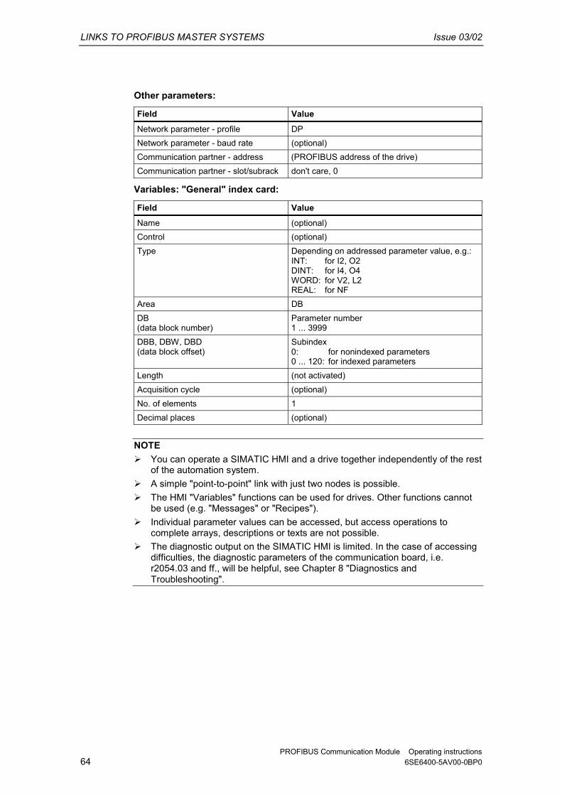
LINKS TO PROFIBUS MASTER SYSTEMS Issue 03/02
PROFIBUS Communication Module Operating instructions 64 6SE6400-5AV00-0BP0
Other parameters:
Field Value
Network parameter - profile DP Network parameter - baud rate (optional) Communication partner - address (PROFIBUS address of the drive) Communication partner - slot/subrack don't care, 0
Variables: "General" index card:
Field Value
Name (optional) Control (optional) Type Depending on addressed parameter value, e.g.:
INT: for I2, O2 DINT: for I4, O4 WORD: for V2, L2 REAL: for NF
Area DB DB (data block number)
Parameter number 1 ... 3999
DBB, DBW, DBD (data block offset)
Subindex 0: for nonindexed parameters 0 ... 120: for indexed parameters
Length (not activated) Acquisition cycle (optional) No. of elements 1 Decimal places (optional)
NOTE ��You can operate a SIMATIC HMI and a drive together independently of the rest
of the automation system. ��A simple "point-to-point" link with just two nodes is possible. ��The HMI "Variables" functions can be used for drives. Other functions cannot
be used (e.g. "Messages" or "Recipes"). ��Individual parameter values can be accessed, but access operations to
complete arrays, descriptions or texts are not possible. ��The diagnostic output on the SIMATIC HMI is limited. In the case of accessing
difficulties, the diagnostic parameters of the communication board, i.e. r2054.03 and ff., will be helpful, see Chapter 8 "Diagnostics and Troubleshooting".

Issue 03/02 LINKS TO PROFIBUS MASTER SYSTEMS
PROFIBUS Communication Module Operating instructions 6SE6400-5AV00-0BP0 65
7.5 Operation on external master systems The MICROMASTER 4 can operate only as a standard DP slave on an external master. Required GSD file The device master file (GSD file) contains all information required by a DP master system to integrate the MICROMASTER 4 into its PROFIBUS-DP configuration as a standard DP slave. Provided the external master system allows the direct integration of GSD files, file SIEM80B5.GSD can be copied directly into the appropriate subdirectory. If the external master is not compatible to this extent, the necessary information must be derived manually from file SIEM80B5.GSD. Exchanging data with MICROMASTER 4 without standard data blocks In cases where block package "Drive ES SIMATIC� cannot be used, the user program must adhere to the system properties with respect to data consistency. This means in particular that system functions of SIMATIC S7 (SFC14 (DPRD_DAT) and SFC15 (DPWR_DAT)) or corresponding means must be used to access > 2 words for the PKW and PZD areas. In this case, the PKW area and PZD area must be regarded as two mutually independent, consistent data areas. PKW PZD PPO1 (4 words) (2 words) PPO3 − (2 words)
Extended PZD: (4 words) (4 words) − (4 words)

LINKS TO PROFIBUS MASTER SYSTEMS Issue 03/02
PROFIBUS Communication Module Operating instructions 66 6SE6400-5AV00-0BP0

Issue 03/02 DIAGNOSTICS AND TROUBLESHOOTING
PROFIBUS Communication Module Operating instructions 6SE6400-5AV00-0BP0 67
8 Diagnostics and Troubleshooting There are two types of diagnostic display: ��Alarm numbers ��Diagnostic parameter
8.1 Diagnostics using alarm number (Alarms and Faults) If alarms and faults occur on the PROFIBUS communication link, corresponding alarm numbers are displayed on the inverter (BOP/AOP).
8.1.1 Alarms
Table 8-1 Alarm Displays on Inverter
Alarm Number
Meaning
A700 Cause: The parameter or configured settings by the PROFIBUS master are invalid.
Remedy: Correct the PROFIBUS configuration A702 Cause: The link to the PROFIBUS is interrupted. Remedy: Check connector, cable and PROFIBUS master A703 Cause: No setpoints, or invalid setpoints (control word = 0) are being
received from the PROFIBUS master Remedy: Check setpoints from the PROFIBUS master. Switch SIMATIC CPU
to "RUN". A704 Cause: At least one configured internode transmitter is not yet active, or has
failed. Remedy: Activate internode transmitter. A705 Cause: No actual values received from inverter. Remedy: None (fault is in inverter) A706 Cause: PROFIBUS-DP communication board: Software error. Remedy: None (fault on the PROFIBUS-DP communication board, for details
see diagnostic parameter) A710 Cause: Inverter has detected failure of communication link to PROFIBUS-
DP communication board Remedy: None (communication board may need to be replaced) A711 Cause: Invalid value of a CB?? parameter. Remedy: Check P0918 (PROFIBUS address) and P2041 (communication
board parameters)

DIAGNOSTICS AND TROUBLESHOOTING Issue 03/02
PROFIBUS Communication Module Operating instructions 68 6SE6400-5AV00-0BP0
8.1.2 Faults Table 8-2 Fault Displays on Inverter
Fault Number
Meaning
A070 Cause: No setpoints received from PROFIBUS-DP communication board.Triggered by A702/A703/A704. The telegram failure time set in P2040 has run out.
Remedy: Check connection to communication partners and ensure valid control word (see A702/A703/A704)
8.2 Diagnostics using diagnostic parameter Detailed diagnostic information is displayed in parameter r2054. The content of the diagnostic parameter depends on the selected diagnostic screen (see communication board parameter P2041.03).
8.2.1 Standard diagnostics Table 8-3 Standard Diagnostic Parameter
(when P2041.03 = 0!) Parameter Meaning
r2054.00 PROFIBUS status: 0: Off 1: Baud rate search 2: Baud rate found 3: Cyclical data exchange (>100: Other diagnostic screen active)
r2054.01 Cyclical PKW channel configured and length of cyclically transmitted setpoints and actual values pxxyy decimal: p: 1/0, PKW configured or not xx: Length setpoints, yy: Length actual values Example: 10404: PKW configured, 4 setpoints and actual values each 204: No PKW configured, 2 setpoints and 4 actual values
r2054.02 Number of acyclical links with class 2 master (PC, OP): 0...2 r2054.03 Error number of last unsuccessful parameter access operation via an
acyclical link (see Table 8-4) r2054.04 Parameter number of last unsuccessful parameter access operation r2054.05 Subindex of last unsuccessful parameter access operation r2054.06 Internode communication:
Active publishers and number of configured publishers. Decimal 0...11114. 1x = Publisher 1, ..., 1xxxx = Publisher 4 active Last decimal place: Number of configured publishers Example: 11114: Four publishers configured, all active 1013: Three publishers configured, first and third active

Issue 03/02 DIAGNOSTICS AND TROUBLESHOOTING
PROFIBUS Communication Module Operating instructions 6SE6400-5AV00-0BP0 69
Parameter accessing error (r2054.04), error numbers < 240 correspond to PKW error numbers:
Table 8-4 Parameter Accessing Errors
No. Cause Remedy (e.g. in ProTool) No. 0 .. 199: Parameter access has been converted to a PKW request. Error detected in inverter. Additional info in r2054.05, r2054.06: Parameter number, index word 0 Parameter number does not exist Check data block number
1 Parameter value cannot be modified - 2 Minimum/maximum not reached or
exceeded -
3 Subindex does not exist Check data block offset 4 Access to single value with array identifier Set data block offset = 0 5 Access to word with double word request or
vice versa Use correct data type (e.g. INT for word, DINT for double word)
6 Setting not allowed (resetting only) - 7 Descriptive element cannot be modified - 11 No status as master control - 12 Key word missing - 17 Request cannot be processed due to
operating state -
101 Parameter number currently deactivated - 102 Channel not wide enough -
104 Illegal parameter value - 106 Request not implemented -
200/ 201
Modified minimum/maximum not reached/exceeded
Minimum/maximum can be further limited in operation
No. 240-249: Parameter access is incorrectly formatted. Error detected on the PROFIBUS-DP communication board. Additional info in r2054.05, r2054.06: Parameter number or S7 data block number, subindex or S7 data block offset. 240 Error in variable address (no additional info) Legal: "Data block" area 241 Data block number illegally formatted Legal: 1...31999 242 Data block offset illegally formatted Legal: 0...116 243 Illegal "type" Legal: CHAR. BYTE, INT, WORD, DINT,
DWORD, REAL 244 Illegal "Number of elements" on accessing
parameter value Legal: Effectively 2 or 4 bytes
248 Illegal text/description modification - 249 Inconsistency in write request: "Type" and
"Number of elements" does not match "Data type" and "Data length"
(error in communication partner)
No. 250: Parameter access has been converted to a PKW request. Response from inverter is errored. Error detected on the PROFIBUS-DP communication board. Additional info in r2054.05, r2054.06: Parameter number, subindex. 250 PKW response does not match request (error in inverter) No. 251: Error detected on the PROFIBUS-DP communication board; no additional info 251 Response too long for response telegram (error in communication partner)

DIAGNOSTICS AND TROUBLESHOOTING Issue 03/02
PROFIBUS Communication Module Operating instructions 70 6SE6400-5AV00-0BP0
8.2.2 Special diagnostics for start-up personnel Irrespective of the setting in P2041.03, the PROFIBUS-DP communication board attempts to send the following diagnostics to the inverter after detecting a software error:
Table 8-5 Special Diagnostics
Parameter Meaning
r2054.00 65535: Identifier for details of a software error r2054.01 ... r2054.05
Name of module in which error has been detected (ASCII code)
r2054.06 Code line in which error has been detected r2054.07 r2054.08
Error details

Issue 03/02 APPENDIX
PROFIBUS Communication Module Operating instructions 6SE6400-5AV00-0BP0 71
9 Appendix
9.1 Technical data
Table 9-1 Technical data
Order number 6SE6401-1PB00-0AA0
Size (height x width x depth)
107mm x 126mm x 50mm
Permissible ambient or coolant temperature - In operation - In storage - In transit
-10° C to +40° C (14° F to 104° F) -25° C to +70° C (-13° F to 158° F) -25° C to +70° C (-13° F to 158° F)
Permissible humidity rating Relative air humidity <= 99 % in operation (condensation not permissible)
Supply voltage 24V ± 10 %, max. 350 mA, from external source Output voltage 5 V ± 10 %, max. 100 mA,
electrically isolated supply for the bus termination of the serial interface
Data transmission rate Max. 12 Mbaud
9.2 EMC information The module complies with the following standards governing radio emissions and interference immunity: ��Radio emissions in accordance with EN55011 1991 Class A ��Interference immunity in accordance with IEC 801-3 and EN61000-4-3

GLOSSARY Issue 03/02
PROFIBUS Communication Module Operating instructions 72 6SE6400-5AV00-0BP0
10 Glossary AK Request identifier
DP Distributed I/Os
ES Engineering System GSD Device master file HSW Main setpoint HIW Main actual value HMI Human Machine Interface LWL Fiber optic conductor OP Operator Panel
PNU Parameter number PWE Parameter value PKW Parameter identifier PZD Process data STW Control word SlaveOM Slave Object Manager TD Text Display ZSW Status word

Suggestions and/or Corrections
Suggestions
Corrections To
Siemens AG Automation & Drives Group SD VM 4 P.O. Box 3269 D-91050 Erlangen Federal Republic of Germany
For Publication/Manual:
COMBIMASTER 411 & MICROMASTER 411 PROFIBUS Module
Suggestions for technical documentation�
User Documentation
From
Name:
Order number: 6SE6400-5AK00-0BP0
Date of Issue: Edition Issue 03/02
Company/Service Department
Address:
Phone: __________ /
Fax: ________ /
Should you come across any printing errors when reading this publication, please notify us on this sheet.
Suggestions for improvement are also welcome.

Siemens AG Automation and Drives Group (A&D) Standard Drives (SD) Division Postfach 3269, D-91050 Erlangen Federal Republic of Germany
© Siemens AG, 2002 Subject to change without prior notice
Siemens Aktiengesellschaft Order No.: 6SE6400-5AV00-0BP0PROFIBUS Communications Module Printed in the Federal Republic of Germany 03.01


