4.11 Geology and Soils - Sound Transit
18
Chapter 4 Affected Environment and Environmental Consequences East Link Project Final EIS 4.11-1 4.11 Geology and Soils July 2011 4.11 Geology and Soils 4.11.1 Introduction to Resources and Regulatory Requirements Geology and soil considerations important to the East Link Project include topography, geology, soil characteristics, groundwater conditions, and geologic hazards. These considerations affect the type of construction methods used for the project and, if not adequately considered during project design, could affect the long-term operations and safety of the light rail system. Washington State’s Growth Management Act (GMA) (Revised Code of Washington [RCW] Chapter 36.70A) requires all cities and counties to identify critical areas within their jurisdictions and to formulate development regulations for their protection. Among the critical areas designated by the GMA are Geologically Hazardous Areas, which are areas susceptible to erosion, sliding, earthquakes, or other geologic events. These hazards could affect the design, construction, and operation of the project and, if not considered appropriately, could pose a risk to public safety. Geology and soil considerations are closely related to groundwater conditions. While this section includes general information on groundwater within segments, more detailed information about groundwater along the alternative routes is discussed in Section 4.9, Water Resources. Locations of possible contaminated soils and contaminated groundwater are identified and discussed in Section 4.12, Hazardous Materials. 4.11.2 Affected Environment Geologic units and soil characteristics along each alternative were assessed within the study area to establish the affected environment for geology and soils. The study area for specific issues related to geology and soils is defined as the area within approximately 100 feet on either side of each alternative and their associated facilities. However, when assessing the geology and soil characteristics, it was also necessary to consider geology on a regional basis to understand the mechanism leading to current geology. The need for a regional review is particularly important to seismicity because the source of this hazard could originate tens to hundreds of miles from the project routes. Sound Transit assessed geologic units and soil characteristics using maps—including topographic maps, surficial soils maps, geologic maps, and geologic hazard maps—published by governmental agencies, including the U.S. Department of Agriculture (USDA) and U.S. Geological Survey (USGS). Sound Transit also assessed available site- specific geotechnical information for each alternative based on geotechnical explorations conducted as part of other projects along the alternative routes. The exploration information includes data from over 500 soil borings that were drilled within the study area between 1948 and 2010 (Exhibit F4.11-7 in Appendix F4.11). As part of conceptual and preliminary engineering for the East Link Project, 114 additional borings were drilled between 2007 and 2010 to augment available subsurface soil and groundwater information in Segments A, B, C, and D (Jacobs, 2007; CH2M HILL, 2011). Information from these project- specific explorations was included in the development of the affected environment description for the study area. 4.11.2.1 Topography, Regional Geology, and Seismicity The East Link Project is located in the central portion of the Puget Sound Basin, an elongated, north-south trending depression situated in western Washington between the Olympic Mountain Range to the west and the Cascade Mountain Range to the east. The regional topography consists of a series of north-south trending ridges separated by deep troughs. The troughs are now occupied by streams, lakes, and waterways, including Puget Sound, Elliott Bay, Lake Washington, and Lake Sammamish. Land elevations range from about 15 to 380 feet (North American Vertical Datum of 1988) across the East Link Project corridor (Exhibit 4.11-1). This regional topography was shaped mainly by glaciations that moved back and forth across the region over 10,000 years ago. The glaciers were sometimes several thousand feet thick. Soils that were over-ridden by glaciers are generally very hard or compact as a result of the weight of the glaciers. More recently, erosional processes and landform changes made by human development of the area have modified the regional topography. Geology in the region generally includes recently developed surficial soils (created within the last 10,000 years) over a thick sequence of glacially consolidated soils and then bedrock. Appendix F4.11 shows the surficial geology of the area (see Exhibits F4.11-1 through F4.11-4) and provides descriptions for each of the geologic units and a summary of their engineering properties (Table F4.11-1). Bedrock along the route is generally located more than 500 feet below the ground surface.
Transcript of 4.11 Geology and Soils - Sound Transit

Chapter 4 Affected Environment and Environmental Consequences
East Link Project Final EIS 4.11-1 4.11 Geology and Soils July 2011
4.11 Geology and Soils
4.11.1 Introduction to Resources and Regulatory Requirements Geology and soil considerations important to the East Link Project include topography, geology, soil characteristics, groundwater conditions, and geologic hazards. These considerations affect the type of construction methods used for the project and, if not adequately considered during project design, could affect the long-term operations and safety of the light rail system.
Washington State’s Growth Management Act (GMA) (Revised Code of Washington [RCW] Chapter 36.70A) requires all cities and counties to identify critical areas within their jurisdictions and to formulate development regulations for their protection. Among the critical areas designated by the GMA are Geologically Hazardous Areas, which are areas susceptible to erosion, sliding, earthquakes, or other geologic events. These hazards could affect the design, construction, and operation of the project and, if not considered appropriately, could pose a risk to public safety.
Geology and soil considerations are closely related to groundwater conditions. While this section includes general information on groundwater within segments, more detailed information about groundwater along the alternative routes is discussed in Section 4.9, Water Resources. Locations of possible contaminated soils and contaminated groundwater are identified and discussed in Section 4.12, Hazardous Materials.
4.11.2 Affected Environment Geologic units and soil characteristics along each alternative were assessed within the study area to establish the affected environment for geology and soils. The study area for specific issues related to geology and soils is defined as the area within approximately 100 feet on either side of each alternative and their associated facilities. However, when assessing the geology and soil characteristics, it was also necessary to consider geology on a regional basis to understand the mechanism leading to current geology. The need for a regional review is particularly important to seismicity because the source of this hazard could originate tens to hundreds of miles from the project routes.
Sound Transit assessed geologic units and soil characteristics using maps—including topographic maps, surficial soils maps, geologic maps, and geologic hazard maps—published by governmental
agencies, including the U.S. Department of Agriculture (USDA) and U.S. Geological Survey (USGS). Sound Transit also assessed available site-specific geotechnical information for each alternative based on geotechnical explorations conducted as part of other projects along the alternative routes. The exploration information includes data from over 500 soil borings that were drilled within the study area between 1948 and 2010 (Exhibit F4.11-7 in Appendix F4.11). As part of conceptual and preliminary engineering for the East Link Project, 114 additional borings were drilled between 2007 and 2010 to augment available subsurface soil and groundwater information in Segments A, B, C, and D (Jacobs, 2007; CH2M HILL, 2011). Information from these project-specific explorations was included in the development of the affected environment description for the study area.
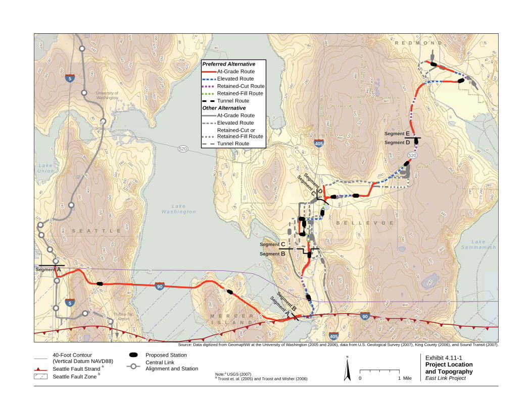
4.11.2.1 Topography, Regional Geology, and Seismicity The East Link Project is located in the central portion of the Puget Sound Basin, an elongated, north-south trending depression situated in western Washington between the Olympic Mountain Range to the west and the Cascade Mountain Range to the east. The regional topography consists of a series of north-south trending ridges separated by deep troughs. The troughs are now occupied by streams, lakes, and waterways, including Puget Sound, Elliott Bay, Lake Washington, and Lake Sammamish. Land elevations range from about 15 to 380 feet (North American Vertical Datum of 1988) across the East Link Project corridor (Exhibit 4.11-1).
This regional topography was shaped mainly by glaciations that moved back and forth across the region over 10,000 years ago. The glaciers were sometimes several thousand feet thick. Soils that were over-ridden by glaciers are generally very hard or compact as a result of the weight of the glaciers. More recently, erosional processes and landform changes made by human development of the area have modified the regional topography.
Geology in the region generally includes recently developed surficial soils (created within the last 10,000 years) over a thick sequence of glacially consolidated soils and then bedrock. Appendix F4.11 shows the surficial geology of the area (see Exhibits F4.11-1 through F4.11-4) and provides descriptions for each of the geologic units and a summary of their engineering properties (Table F4.11-1). Bedrock along the route is generally located more than 500 feet below the ground surface.
!!
!!
!!
!!
!!
!!!!
!!
!!
!!
!!
!!
!!
!!
!
!
!!!
!
!!
!
!!
!!
!!
!!
!!
!
!!
!!
!!
!
!!
!
!!
!
!
!!
!!
!!
!!
! ! ! ! ! ! ! ! !!
!!
!!
!!
!
!!
! ! ! !
!!
!!
!!
!
!!
!!
!!
! !
!!
!!
!!
! ! ! ! ! ! !!
!
!!
! ! ! !
!!
!!
!!
!! !!
!!
!!
!!
!
!
!!
!
!!!
!!
!
!
!
!!!
!!
!!
!!
!!!
!
!!
!!
!!
!
!!
!!
!!
!!
!
!!!
!
!!
!!
!!
!
!!
!
!!
!
!!
!
!!
!
!
!!
!
((((((((((((((((((((((((((((((
((((((
((((((((((((((
((
((((((
((((((((((
L a k eW a s h i n g t o n
L a k eS a m m a m i s h
L a k eU n i o n
¾À520
¾À520
Segment B
Segment A
To Sea-TacAirport
University ofWashington
Segment A
Segment D
Segment D
Segment C
§̈5
§̈90
§̈5
§̈405
§̈90
§̈405
Segment CSegment B
Segment E
NE 6TH
S E A T T L E
M E R C E RI S L A N D
B E L L E V U E
R E D M O N D
240
200
280
80
320
40
160
120
360
400
0
440
480
520
480
360
80
280
520
360
0
200
0
40
240
40
80
80
280
160
280
80
320
320
280
0
240
16040
120
0
120
160
200
240
240
240
120
440
120
200
320
160
320
40
0
80
320
0
160
0
80 360
80
0
440
0
440
0
400
120
200
120
400
160
0
0
200
400
320
320
40
360
40
360
280
400
160
160
440
240
280
160
80
80
80
80
120
320
160
360
320
160
200
160
200
80
200
240
40
360
240
0
320
40
120
440
360
40
0
200
160
80
120
280
240
200
160
80
40
40
520
0
160
160
280
360
400
240
0
40
320
40
320160
320
240
240
160
120
320
200
80
800
4080
120
160
40
320
280
120
240
40
280
240
440
480
440
120
200
40
120
120
360
0
160
360
320
200
160
400
160
240
40
40
0
280
120
360
0
200
160
0
40
240
0
160
200
160
0
520
280
0
320
80
320
120
320
0
240
80
0
200
120
280
160
440
0
120
40
40
120
0
80
120
80
280
240
0
280
0
0
280
240
120
200
320
40
240
320
0
240
200
320
160
40
80
160
200
360
0
0 1 Mile§Exhibit 4.11-1Project Location and TopographyEast Link Project
40-Foot Contour(Vertical Datum NAVD88)
(( Seattle Fault Strand a
Seattle Fault Zone b
ú Proposed Station
!!Central LinkAlignment and Station
Source: Data digitized from GeomapNW at the University of Washington (2005 and 2006), data from U.S. Geological Survey (2007), King County (2006), and Sound Transit (2007).
Note:a USGS (2007)B Troost et. al. (2005) and Troost and Wisher (2006)
Preferred AlternativeAt-Grade RouteElevated Route
! ! ! ! Retained-Cut Route! ! ! ! Retained-Fill Route
Tunnel RouteOther Alternative
At-Grade RouteElevated Route
! ! ! !
Retained-Cut or Retained-Fill RouteTunnel Route

Chapter 4 Affected Environment and Environmental Consequences
East Link Project Final EIS 4.11-3 4.11 Geology and Soils July 2011
The region is seismically active—the project vicinity has been subject to earthquakes in the historical past and will undoubtedly experience earthquakes again in the future. Earthquakes in the Puget Sound region result from any one of three sources: the Cascadia subduction zone off the coast of Washington, the deep intraslab subduction zone located approximately 20 to 40 miles below the Puget Sound area, or shallow crustal faults. The closest active crustal source is the Seattle Fault Zone. The southern portion of the project is mapped within the Seattle Fault Zone. The northern terminus of the light rail project in Redmond is located within 6.5 miles of the Seattle Fault Zone (USGS, 2007) (as shown in Exhibit 4.11-1).
4.11.2.2 Geologic Hazards An important consideration for the construction and operation of the East Link Project would be the potential for geologic hazards, including steep slopes, erosion, landslides, seismicity, and soft soils. Geologic hazards from seismicity include ground-shaking, fault movement, and secondary seismic impacts such as liquefaction and liquefaction-induced settlement. Table 4.11-1 identifies the type of geologic hazard areas within or adjacent to each segment. Areas with hazards from liquefaction, steep-slopes, landslides, and peat deposits, are shown in Appendix F4.11, Exhibits F4.11-5 and -6. The geologic hazard potential identified in Table 4.11-1 was established based on Washington state and local regulatory requirements involving steep slopes, erosion, landslides, seismic hazards, and soft soils. The geologic hazard potentials are defined as follows:
Steep slope hazards are areas where slopes are steeper than 15 to 40 percent. These areas are considered hazards because they are prone to slope failure, either during periods of wet weather or during large seismic events.
Erosion hazards occur where soils may experience severe to very severe erosion from construction activities. Certain types of soils with fine particles, such as silts, are more prone to erosion from wind and water. The potential for erosion also increases as the slope steepness increases. Surficial soils and topographic maps can be used to identify areas that are particularly susceptible to erosion.
Landslide hazard areas are mapped where there is evidence of past landslides, where the slope is 15 percent to 40 percent and the soils are underlain by silt or clay that can perch groundwater, or where the slope is steeper than 40 percent, regardless of soil type. This type of hazard is closely associated with the steep slope hazard. A landslide can vary in size from a small, surficial slump to a large, multi-acre occurrence.
TABLE 4.11-1 Potential Geologic Hazards within or Adjacent to Each Segment
Geologic Hazard Potential
Segment
A B C D E
Steep slopes (more than 40 percent)
Erosion
Landslide
Seismic (distance from Seattle Fault Zone) 0 to 2 miles 0 to 2 miles 2 to 3.5 miles 3.5 to 5 miles 5 to 6.5 miles
Liquefaction potential Moderate to high Moderate to high Low to moderate Low to moderate Low to moderate
Soft soils (including peat settlement)
Geology and Soils Definitions
Cascadia subduction zone is the place where the Juan de Fuca and North American lithospheric plates (the crust and the uppermost mantle of the earth) come together, with the Juan de Fuca sliding below the North American Plate.
Groundwater is water that is found beneath the earth’s surface. The top of the groundwater is referred to as the water table. The water table location can change with the season.
Intraslab subduction zone is the zone between the earth’s crustal plates. This zone is the source of large earthquakes below Puget Sound.
Liquefaction is a loss of strength in loose sands and non-plastic (i.e., with little or no cohesion) silts located below the water table.
Lateral spreading is the lateral movement of near-level or sloping ground associated with liquefaction of soil during an earthquake.
Surface faulting is displacement of the land surface by movement along the fault.
Tsunami is a sea wave resulting from an underwater landslide or seafloor movement during an earthquake.
Seiches are periodic oscillations in an enclosed body of water during an earthquake.

Chapter 4 Affected Environment and Environmental Consequences
4.11 Geology and Soils 4.11-4 East Link Project Final EIS July 2011
Seismic hazard areas are subject to potential risk from earthquake-induced ground-shaking and fault displacement. The ground-shaking can result in slope failure, settlement, soil liquefaction, a tsunami, or a seiche—all of which pose a risk to the public.
Liquefaction is of particular concern because it has often been the cause of damage to structures during past earthquakes. Liquefaction occurs where soils are primarily loose and granular in consistency and located below the water table. The consequences of liquefaction include loss in the strength and settlement of the soil. The loss of strength can result in lateral spreading, bearing failures, or flotation of buried vaults and pipes.
Examples of liquefiable soils located in the study area include:
Some artificial fill Tideflat deposits Mass wastage deposits Lake deposits Recessional outwash deposits
A tsunami or a seiche is a possible secondary impact from a seismic event. Both mechanisms involve water waves that can be created by an earthquake. In general, the East Link alternatives are located either too far from Elliott Bay and Lake Sammamish or too high above Lake Washington for tsunami or seiche inundation to be a concern.
Soft soil conditions can also be a form of geologic hazard. Peats and soft clays are common soils that result in geologic hazards. These soils have low strengths and are compressible. Without appropriate design consideration, soft soil can lead to embankment failures during construction or long-term settlement and would add to the maintenance requirements for the project.
4.11.2.3 Site Geology This section summarizes geotechnical characteristics and groundwater conditions for each segment of the study area based on existing geologic maps and geotechnical boring logs. Table F4.11-1 in Appendix F4.11 provides a summary of general geologic unit descriptions. More detailed discussions of the soils and geologic units, as well as groundwater conditions along the segment routes, are provided in geotechnical reports prepared for conceptual and preliminary engineering (Jacobs, 2007; CH2M HILL, 2011).
Segment A The construction of Interstate 90 (I-90) and adjacent land development has modified the terrain within Segment A, changing the original topography and sometimes altering the type of exposed soil or the depth to groundwater.
The geotechnical characteristics of soils in this segment range from loose sands, which could be unstable if they were to liquefy, to glacially consolidated sands and gravels, which generally provide good bearing support and little settlement.
The groundwater elevation varies along the Segment A alternative.
Groundwater in the Rainier Valley was typically found at around 20 feet deep and was not encountered in many borings on the hillsides.
Artesian groundwater conditions were encountered at depths of approximately 30 to 60 feet below the ground surface on the east side of Baker Ridge at the west approach to the I-90 floating bridge. Artesian conditions occur when groundwater is at a greater pressure than the water depth at which groundwater is encountered because a low-permeability soil layer prevents the groundwater from flowing upward.
Groundwater near each shore of Mercer Island was encountered at the lake level, while groundwater within the center of Mercer Island was approximately 20 feet below the ground surface.
Segment B Much of the land along the Segment B corridor has been developed with residential and light commercial structures for retail uses. The Mercer Slough Nature Park, which is a large wetland between Bellevue Way SE and I-405, remains relatively undeveloped.
Soil conditions change significantly within Segment B, depending on the proximity of the location to Mercer Slough Nature Park:
Within the Mercer Slough Nature Park, soft clays and peats are found. These soils are often low in strength and prone to settlement. WSDOT has found the thickness of the soft soil to be in excess of 100 feet at the center of the slough. In addition to being soft and settlement prone, WSDOT also reports that these soils move horizontally as the level of Lake Washington changes, resulting in large soil loading to the existing I-90 structures that cross the slough.

Chapter 4 Affected Environment and Environmental Consequences
East Link Project Final EIS 4.11-5 4.11 Geology and Soils July 2011
Away from Mercer Slough, such as along Bellevue Way SE and 112th Avenue SE and along the former BNSF Railway corridor, glacially consolidated soils are found close to the ground surface. These soils are very strong and resistant to settlement, making them very stable during construction and long-term operations.
Steep slopes are present in areas along the west side of Bellevue Way SE and along the east side of the former BNSF Railway corridor.
Groundwater depth varies with topography and the season.
Kelsey Creek, to the northeast of Mercer Slough, has a shallow unconfined aquifer, which primarily discharges into Mercer Slough.
Within the Mercer Slough wetlands, groundwater is at or near the ground surface. It also is present and highly pressurized (artesian) in a sand unit at approximately 100 to 125 feet below the ground surface.
In upland areas on either side of the Mercer Slough, groundwater is often encountered within 10 to 30 feet of the ground surface.
Segment C Development in Segment C varies from homes, apartments, hotels, and relatively low-rise commercial buildings in the south to Downtown Bellevue, which is dominated by highrise buildings and an extensive amount of underground development for parking garages, building foundations, and utilities. Most of the land in Segment C has been modified by human development.
Soils consist of fill, underlain by deposits of glacial till composed of silt, sand, and gravel.
The fill is usually less than 15 feet in thickness and is the result of the extensive construction that has taken place in the area. Fill areas along 112th Avenue SE and in the Downtown Bellevue core are highly variable in terms of soil type and consistency. The variability of this fill makes it less dependable for construction, and it can be prone to settlement and/or liquefaction.
The till below the fill is generally very compact and stable, thus providing good bearing support and posing limited risk of settlement, which makes these soils suitable for constructing and operating various light-rail alternatives, including tunnel options.
Segment C includes alternatives that would involve tunneling through Downtown Bellevue. Geotechnical
characteristics and groundwater conditions along potential tunnel alternatives within Segment C are described in Table 4.11-2. This table also identifies typical tunneling methods and tunneling depths for each alternative.
The groundwater elevation varies with topography and season in Segment C. A groundwater table is typically encountered at depths between 20 and 100 feet. In some locations of Downtown Bellevue, there is artesian groundwater pressure. These excess pressures would have to be considered when designing and constructing tunnels and elevated structures.
The presence of relatively shallow groundwater in some locations has meant that dewatering wells have been used to lower groundwater during excavation of basements for new highrise buildings in some parts of Downtown Bellevue, such as at the recently constructed Bravern office buildings. Dewatering during construction can increase the potential for settlement where soils are soft or loose and heavily saturated. At these locations the extent of dewatering would need to be monitored closely to avoid damage to buildings, streets, or utilities from settlement induced by dewatering. Previous excavation experience in Downtown Bellevue indicates that loose or soft soils are fairly shallow and localized, thereby limiting this risk relative to other areas.
Segment D Land within Segment D varies from a relatively level to gently sloping upland area. Several streams travel through the area toward Lake Washington. This area is dominated by light industrial uses and retail businesses. These developments have modified most of the land. Soil conditions consist primarily of layered sand and gravel. In some localized areas, sands and gravels are of loose or medium density, making these soils potentially prone to liquefaction during a large seismic event. Other areas of glacial till are heavily overconsolidated from the weight of past glaciations, resulting in very high bearing strengths and little potential for settlement or liquefaction. There are steep slopes in areas on the south side of SR 520.
The groundwater elevation in the vicinity of NE 12th Street and the former BNSF Railway corridor is located within 10 to 20 feet of the ground surface, as indicated by the water level in Lake Bellevue. In other areas along the alternative, groundwater was typically encountered between the surface and 15 feet deep or at greater depths, between about 45 and 60 feet. In some locations, there are artesian conditions, indicating that water is confined by low-permeability layers.

Chapter 4 Affected Environment and Environmental Consequences
4.11 Geology and Soils 4.11-6 East Link Project Final EIS July 2011
TABLE 4.11-2 Geological Conditions for Tunnel Alternatives
Alternative Geotechnical Characteristics Groundwater Conditionsa
Types of Tunnels
Proposed
Depth of Expected
Excavation
Preferred 110th NE Tunnel Alternative (C9T)
Minimal fill except for some localized areas of up to 5 feet of loose fill. Medium dense to very dense glacial till underlain by very dense advance outwash and very stiff to hard clay and silt.
Depth to groundwater is generally between 30 and 50 feet. Near NE 2nd Street, groundwater was encountered in sand lenses between 12 to 28 feet deep.
Cut and cover Up to 60 feet
Bellevue Way Tunnel Alternative (C1T)
10 to 15 feet of medium dense fill underlain by very dense glacial till and advance outwash.
Depth to groundwater varies between 65 feet and 90 feet.
Cut and cover, SEM under Bellevue Arts Museum
South of NE 6th Street: up to 80 feet
East of Bellevue Way: up to 55 feet
106th NE Tunnel Alternative (C2T)
Conditions unknown south of Main Street. North of Main Street there is minimal fill until NE 6th Street, which is up to 17 feet of medium dense advance outwash underlain by very dense advance outwash. Along NE 6th Street, there is up to 15 feet of medium dense fill underlain by very dense glacial till and stiff to hard glacial lake deposits.
Depth to groundwater is approximately 50 feet south of NE 6th Street. At the Bellevue Transit Center Station, no groundwater was encountered in borings up to 90 feet deep. Groundwater depth unknown north of NE 6th Street.
Cut and cover, bored tunnel
Up to 55 feet
108th NE Tunnel Alternative (C3T)
Conditions unknown south of Main Street. North of Main Street is very dense glacial till, advance outwash, and very stiff silt. At the Bellevue Transit Center Station and north to NE 10th Street, there is up to 16 feet of very loose to medium dense fill underlain by dense glacial till and advance outwash and stiff to very stiff glaciolacustrine deposits. North of NE 10th Street, there is up to 15 feet of loose to medium dense fill underlain by very dense glacial till consisting of sand with silt and silty gravel.
Depth to groundwater is approximately 47 feet south of NE 6th Street. At the Bellevue Transit Center Station, no groundwater was encountered in borings up to 90 feet in depth. Groundwater depth unknown north of NE 6th Street.
Bored, except for cut and cover at tunnel portals and stations
Between 80 and 110 feet for bored sections
Up to 65 feet for cut and cover tunnels, and 110 feet at cut and cover Bellevue Transit Center Station
a Groundwater depths are approximate and can vary by several feet with the season. Development in the area can also change the depth to the groundwater table.
SEM = sequential excavation mining
Segment E The area within Segment E transitions from a higher ridge to the Sammamish River Valley. Lake Sammamish and the Sammamish River have influenced the geology and soils of this area. Areas to the west of Sammamish River are upland areas dominated by residential and commercial development. Land east of the Sammamish River and south of SR 520 is a low relatively flat valley area containing a large county park. The area east of the Sammamish River and north of SR 520 consists of a relatively flat area developed with residential and commercial structures forming Downtown Redmond. Soil conditions vary between the upland area and the valley area. In the upland area, geological conditions are similar to those in Segment D. In the valley, soils consist of an upper layer of fill, underlain by sand and
gravel and layers of soft, compressible peat and clay up to 25 feet deep. These soils are less suitable for construction and some are prone to liquefaction. Dense glacially consolidated soils are located beneath the fill and surface soil deposits. There are steep slopes in areas along the west side of West Lake Sammamish Parkway.
The groundwater elevation varies in Segment E. In the upland area, zones of groundwater are encountered from the surface to 20 feet deep or more. Adjacent to the Sammamish River, groundwater is within 3 feet of the ground surface in undisturbed areas and deeper in areas where fill has been placed. In the valley area, away from the Sammamish River and Bear Creek, groundwater is encountered at about 20 feet deep.

Chapter 4 Affected Environment and Environmental Consequences
East Link Project Final EIS 4.11-7 4.11 Geology and Soils July 2011
Maintenance Facility Surroundings Four potential locations have been identified for siting a maintenance facility. Three of these are located in Segment D, and one is located in Segment E. The surface geology and soil conditions at the ground surface in those locations have been modified by human development. Geotechnical characteristics and groundwater conditions are generally as described above for Segments D and E.
4.11.3 Environmental Impacts This section summarizes the impacts that could result from the East Link Project and the No Build Alternative. The discussion of impacts covers the general impacts that are common to all segments, and then the key impacts for each segment are discussed.
4.11.3.1 No Build Alternative Under the No Build Alternative, the East Link Project would not be constructed. The existing geology and soils environment would essentially remain unchanged. The existing risk from seismic hazards would still exist. New development would continue to take place, thus resulting in more geologic risk from existing steep slope, erosion, and seismic hazards.
4.11.3.2 Impacts during Operation Impacts Common to All Build Alternatives Operational impacts would result from new excavation slopes and new earth fills required for the light rail facilities. Other impacts would be related to geologic hazards that already exist. For example, there would be a risk of seismic events during the period of operation, and this risk could result in other related geologic hazards, such as liquefaction and seismic-induced slope failures. These hazards could represent risks to the public using the light rail facilities if not adequately considered during project design and construction.
Potential long-term operational impacts that are common to each of the segments are discussed in the following subsections.
Insufficient Stability of Earth Slopes and Retaining Structures Insufficient long-term stability of earth slopes and retaining wall structures could endanger on-site and off-site properties. The earth slopes could include natural slopes, slopes that have been steepened to meet alignment requirements, or slopes for embankment fills. This risk would be greater if a large seismic event were to occur.
The overall risk of impacts from slope and retaining wall failures would be low for all alternatives. Slope and retaining wall stability would be considered
during the design phases of the project, and various mitigation measures could be implemented to stabilize areas of potential risk.
Seismic Ground-Shaking The project study area is within a seismically active area. Consequences of a seismic event occurring during operations would be strong ground-shaking, which would cause increased inertial loading and movement within structures supporting the light rail system. The ground-shaking could also lead to liquefaction of loose, saturated, cohesionless soils; settlement from densification of loose soils; instability of steep slopes; or increased earth pressures on retaining walls. These impacts could damage the constructed light rail facilities and endanger people using the facility.
The elevated light rail support systems and earth-retaining structures, including retained fills or cuts, would be designed for both the seismic ground-shaking level and the consequences from ground-shaking. The East Link Project would meet current seismic design standards required to minimize the long-term risks to the system and the public. These standards are based on the occurrence of a very rare seismic event.
The tunnel alternative should perform well during strong ground-shaking based on the performance of tunnels around the world during past earthquakes when appropriate designs were applied. The latest seismic design methods would be used to ensure good performance.
Long-Term Settlement from New Earth Fills New earth fills would be used in some areas to meet track-grade requirements. Walls would typically be used to retain the fill, thereby minimizing the area covered by fill. The fill would cause new earth loads on the existing soil, which could lead to settlement of soft soil.
Settlements from new earth loads could occur in areas that have soft surface soils. Although settlement-prone soils could occur anywhere along the alternatives, the areas of primary concern are near Mercer Slough, near Lake Bellevue, and in the Sammamish River valley where soft, compressible soils have been identified. Where glacially consolidated soils occur at the ground surface, the potential for settlements from new earth loads would be minimal because these soils have already been compressed by the weight of ancient glaciers.
The new earth loads would cause compression of soft soils below and adjacent to the new construction. The extent of compression beyond the footprint of the new

Chapter 4 Affected Environment and Environmental Consequences
4.11 Geology and Soils 4.11-8 East Link Project Final EIS July 2011
earth load can extend 20 feet or more from the load. The impacts on adjacent areas could include the following:
Settlement of buildings or residential structures Damage to roadways and sidewalks, resulting in
additional maintenance work Damage to buried utilities located next to new fill
Additional geotechnical assessment during final design would be focused on identifying the location of these soft soils. Where found, they could either be replaced, or ground improvement techniques would be used to prevent long-term settlement. Another option in some locations would be to use lightweight fill rather than normal earth fill. These lightweight materials include extruded polystyrene (geofoam) or cellular concrete.
Settlement of compressible soils beneath proposed retaining structures and fill areas could require periodic maintenance of the new infrastructure, which could minimize potentially poor ride quality when maintenance is not performed. Utilities or other structures located adjacent to the new facilities could also settle as a result of increased loads. Over much of the project corridor, the existing soils would provide excellent bearing support, and the potential for long-term settlement would be negligible. In areas where settlement-prone soils exist, mitigation measures would be used to avoid the detrimental impacts of settlements.
Summary The degree of the impacts described above in each segment would depend on the specific site conditions, development plans, and final design. In all cases, the severity or frequency of the hazard or impact could be avoided or minimized using conventional design and construction methods. Where impacts are found to be moderate to high, more effort would be required during design to evaluate the severity of the impact and identify an adequate avoidance or minimization method. The most important geologic hazard for operations would result from seismic ground-shaking, which would affect all segments, although the hazard would be slightly higher in Segments A and B because of their proximity to the Seattle Fault Zone where the risks from fault movement and ground-shaking are higher. In other segments, the primary seismic hazard would be associated with ground-shaking and secondary impacts of ground-shaking, such as liquefaction, slope failures, and ground settlement.
Segment A Preferred Interstate 90 Alternative (A1) travels along the existing I-90 roadway in the current HOV lanes. The
route would offer overall stable geology and soil conditions during operation except in a limited number of areas. The primary geologic hazards would be strong ground-shaking from a large seismic event in the region or rupture of the Seattle Fault. Portions of the Rainier Valley and the east approach of the I-90 floating bridge are the most vulnerable areas for these hazards. The potential for fault movement along the Segment A route is believed to be very low because of the unlikely occurrence of a rupture and the low likelihood that any fault displacement would occur along the track alignment.
Segment A includes the use of the I-90 existing structures, which were designed during the 1970s and mid 1980s. These structures were designed to meet seismic requirements at the time of construction in the early 1980s. The light-rail system design would be such that placing the light rail on the I-90 structures would not increase their seismic vulnerability.
Sound Transit also commits to funding retrofits necessary to meet current earthquake-resistant structural design requirements. Structures assumed to be retrofitted include the columns, bridge seats, and restrainers for the light rail portions of the D2 Roadway, Rainier Avenue overcrossing, approach spans to the floating bridge, and the East Channel Bridge. These retrofits would be accomplished using current Federal Highway Administration (FHWA)/ American Association of State Highway and Transportation Officials (AASHTO) policies, consistent with WSDOT’s own practices for retrofitting existing structures. The floating bridge is generally not vulnerable to seismic events due to the dampening effect of the lake water.
Segment B Along Bellevue Way SE, Preferred 112th SE Modified Alternative (B2M) includes elevated, at-grade, and retained cut portions. This alternative would not affect the slopes on the west side of Bellevue Way SE. However, retaining walls would be required to support the cuts along much of the length on the east side; heights of these retaining walls could be greater than 20 feet. Deposits of liquefiable soils occur in some locations along the Bellevue Way SE portion of the Preferred Alternative B2M route. These soils would be replaced or improved. Ground improvement measures could include the use of vibrodensification
Vibrodensification is a ground improvement process used in cohesionless soils to make the soil denser. The vibrator action, usually accompanied by water jetting, reduces the intergranular forces between the soil particles, thereby allowing the soil particles to move into a denser configuration. Compaction can be achieved above and below the water table.

Chapter 4 Affected Environment and Environmental Consequences
East Link Project Final EIS 4.11-9 4.11 Geology and Soils July 2011
methods, the installation of stone columns, or cement deep soil mixing.
The South Bellevue Park-and-Ride Lot would likely be supported on drilled shaft foundations. This type of foundation is routinely used in the Puget Sound area. The depth of the drilled shaft would extend to glacial tills located within 50 feet of the ground surface.
Preferred Alternative B2M would be located within a lidded, below-grade, retained cut next to the Winters House. The retained cut would consist of retaining walls to support soil on either side of the track. Soils along the retained cut and supporting the Winters House are competent silts, sands, and gravels. Construction methods would be selected to prevent vertical or lateral movement of the soil, thereby minimizing potential for settlement of Bellevue Way SE and of the Winters House.
The retaining walls used to construct the retained cut would potentially create a barrier to groundwater flow originating from west of Bellevue Way SE. However, the sealed, concrete-lined retained cut would prevent groundwater from entering the retained cut but would allow groundwater to flow down-gradient beneath the cut. Additional potential mitigation measures are discussed in Section 4.9, Water Resources.
The Preferred Alternative B2M route along 112th Avenue SE runs along one of the Mercer Slough channels (Mercer Slough West) located just to the east of the planned route. Soils generally comprise a limited depth of fill over glacial till except in the vicinity of SE 15th Street, where a deeper thickness of soft material was encountered.
This section of the route would have retaining walls and embankment fills to meet track-grade requirements. Additional slope stability, settlement, and localized liquefaction issues would be implemented with this alternative compared with the alternatives within the median of 112th Avenue SE.
Preferred Alternative B2M would potentially involve maintenance issues adjacent to the north end of the Mercer Slough from long-term settlement of soft clays and peats and would be at a higher risk from liquefaction of saturated sands in Mercer Slough than other Segment B alternatives.
The other Segment B alternatives include at-grade and elevated alternatives located in south Bellevue. These alternatives also would potentially be impacted by ground conditions, as discussed below.
Within Segment B, at-grade alternatives adjacent to the north end of Mercer Slough (112th SE At-Grade Alternative [B2A], 112th SE Bypass Alternative [B3],
and Alternative B3 - 114th Extension Design Option [B3 - 114th Design Option]) would potentially involve more maintenance issues because of long-term settlement of soft clays and peats. These alternatives would be at a higher risk for liquefaction in saturated sands than the Bellevue Way Alternative (B1) that runs along Bellevue Way SE and the 112th SE Elevated Alternative (B2E) that is elevated with foundations in competent load-bearing soils.
The slopes along Bellevue Way SE and 112th Avenue SE would require the use of retaining walls to accommodate the roadway widening for the rail system for Alternatives B1, B2A, B3, and B3 - 114th Design Option and Preferred Alternative B2M. Heights of the walls are generally limited to 20 feet or less and can be designed to provide long-term stability, even where slopes are located above the walls. Alternative B2E would generally involve fewer cuts into existing slopes than alternatives that have at-grade sections (Alternatives B1, B2A, B3, and B3 - 114th Design Option and Preferred Alternative B2M) and, therefore, would involve less risk for long-term slope failures. The grade changes along 112th Avenue SE (with Alternatives B2A, B3, and B3 - 114th Design Option and Preferred Alternative B2M) are lower than along Bellevue Way SE (with Alternative B1), suggesting that the 112th Avenue SE alternatives would involve less risk from a sloping ground standpoint.
The BNSF Alternative (B7) includes an elevated structure across Mercer Slough. Soils along the slough consist of very soft peats and clays to a depth of 60 to 100 feet. Support for an elevated structure at the center of the slough crossing would have to be developed at depths of greater than 120 feet because of the thickness of soft soils.
Results of a geotechnical WSDOT monitoring program also show that soils move towards the center of the slough during annual changes in water levels within Lake Washington. The extent of movement has resulted in large soil loading to existing WSDOT bridges, forcing WSDOT to implement special bridge repairs to maintain operation and safety of their bridges.
The slough crossing for Alternative B7 would have to be designed to accommodate these soils loadings. Furthermore, Sound Transit would have to consult closely with WSDOT to ensure that the locations of the Sound Transit structures do not increase loads on existing WSDOT I-90 structures. Elevated structures would also be required for Alternative B7, beginning about one-half mile south of SE 8th Street, to meet grade requirements and because of the likelihood of encountering soft, compressible soils in the upper 10
Chapter 4 Affected Environment and Environmental Consequences
4.11 Geology and Soils 4.11-10 East Link Project Final EIS July 2011
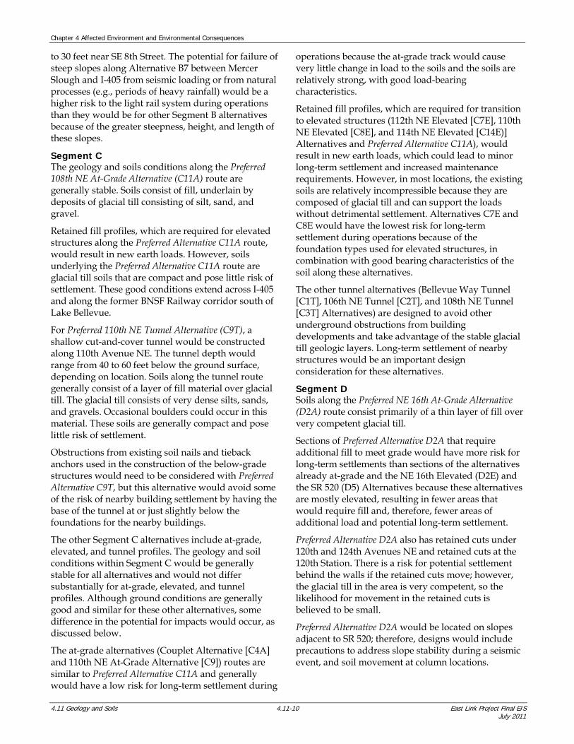
to 30 feet near SE 8th Street. The potential for failure of steep slopes along Alternative B7 between Mercer Slough and I-405 from seismic loading or from natural processes (e.g., periods of heavy rainfall) would be a higher risk to the light rail system during operations than they would be for other Segment B alternatives because of the greater steepness, height, and length of these slopes.
Segment C The geology and soils conditions along the Preferred 108th NE At-Grade Alternative (C11A) route are generally stable. Soils consist of fill, underlain by deposits of glacial till consisting of silt, sand, and gravel.
Retained fill profiles, which are required for elevated structures along the Preferred Alternative C11A route, would result in new earth loads. However, soils underlying the Preferred Alternative C11A route are glacial till soils that are compact and pose little risk of settlement. These good conditions extend across I-405 and along the former BNSF Railway corridor south of Lake Bellevue.
For Preferred 110th NE Tunnel Alternative (C9T), a shallow cut-and-cover tunnel would be constructed along 110th Avenue NE. The tunnel depth would range from 40 to 60 feet below the ground surface, depending on location. Soils along the tunnel route generally consist of a layer of fill material over glacial till. The glacial till consists of very dense silts, sands, and gravels. Occasional boulders could occur in this material. These soils are generally compact and pose little risk of settlement.
Obstructions from existing soil nails and tieback anchors used in the construction of the below-grade structures would need to be considered with Preferred Alternative C9T, but this alternative would avoid some of the risk of nearby building settlement by having the base of the tunnel at or just slightly below the foundations for the nearby buildings.
The other Segment C alternatives include at-grade, elevated, and tunnel profiles. The geology and soil conditions within Segment C would be generally stable for all alternatives and would not differ substantially for at-grade, elevated, and tunnel profiles. Although ground conditions are generally good and similar for these other alternatives, some difference in the potential for impacts would occur, as discussed below.
The at-grade alternatives (Couplet Alternative [C4A] and 110th NE At-Grade Alternative [C9]) routes are similar to Preferred Alternative C11A and generally would have a low risk for long-term settlement during
operations because the at-grade track would cause very little change in load to the soils and the soils are relatively strong, with good load-bearing characteristics.
Retained fill profiles, which are required for transition to elevated structures (112th NE Elevated [C7E], 110th NE Elevated [C8E], and 114th NE Elevated [C14E)] Alternatives and Preferred Alternative C11A), would result in new earth loads, which could lead to minor long-term settlement and increased maintenance requirements. However, in most locations, the existing soils are relatively incompressible because they are composed of glacial till and can support the loads without detrimental settlement. Alternatives C7E and C8E would have the lowest risk for long-term settlement during operations because of the foundation types used for elevated structures, in combination with good bearing characteristics of the soil along these alternatives.
The other tunnel alternatives (Bellevue Way Tunnel [C1T], 106th NE Tunnel [C2T], and 108th NE Tunnel [C3T] Alternatives) are designed to avoid other underground obstructions from building developments and take advantage of the stable glacial till geologic layers. Long-term settlement of nearby structures would be an important design consideration for these alternatives.
Segment D Soils along the Preferred NE 16th At-Grade Alternative (D2A) route consist primarily of a thin layer of fill over very competent glacial till.
Sections of Preferred Alternative D2A that require additional fill to meet grade would have more risk for long-term settlements than sections of the alternatives already at-grade and the NE 16th Elevated (D2E) and the SR 520 (D5) Alternatives because these alternatives are mostly elevated, resulting in fewer areas that would require fill and, therefore, fewer areas of additional load and potential long-term settlement.
Preferred Alternative D2A also has retained cuts under 120th and 124th Avenues NE and retained cuts at the 120th Station. There is a risk for potential settlement behind the walls if the retained cuts move; however, the glacial till in the area is very competent, so the likelihood for movement in the retained cuts is believed to be small.
Preferred Alternative D2A would be located on slopes adjacent to SR 520; therefore, designs would include precautions to address slope stability during a seismic event, and soil movement at column locations.

Chapter 4 Affected Environment and Environmental Consequences
East Link Project Final EIS 4.11-11 4.11 Geology and Soils July 2011
Preferred Alternative D2A includes a storage track north of the NE 12 Street undercrossing and where the track alignment turns from north-south to east-west. Soils along the tail-track section generally consist of a thin layer of fill over very competent sands and gravels. This section of the track was used for many years by BNSF Railway without impacts from local soils and geology; therefore, the tail track would have few impacts to or from soils and geology. Planned development associated with the tail track (i.e., parking area and a small building) also appear to be suitable for the soils and geology in this area.
The other Segment D design options include at-grade, retained cut, and elevated alternatives located in east Bellevue and west Redmond. Soils along the Alternative D2A - 120th Station Design Option and the Alternative D2A - NE 24th Design Option are similar to Preferred Alternative D2A. These soils consist of a thin layer of fill over very competent glacial till. Potential impacts associated with these design options are as summarized below.
The D2A - 120th Design Option has the same footprint location but has at-grade crossings and an at-grade station, which would overall be lower risk than retained-cut crossings and a station constructed using retained cuts because there is not the potential for cut-slope movement and potential settlement behind retaining walls.
The D2A - NE 24th Design Option has at-grade and elevated components. The fills for this design option would overall be minor, but there would be an approach fill supported by a mechanically stabilized-earth (MSE) wall from the elevated structure to at-grade. New earth loads from the fill could result in settlement of the approach fill, the adjacent roadway, and utilities located near the new fill. Soils in this have very good load bearing characteristics; therefore, the potential for settlement would be low. The D2A - NE 24th Design Option also runs along NE 24th Street rather than along SR 520, thus avoiding some of the slopes along SR 520 and having a lower risk for slope movement during a seismic event than Preferred Alternative D2A.
Like the other segments, the geology and soil conditions for other alternatives within Segment D would be generally stable for all alternatives and would not differ substantially for at-grade and elevated profiles. Potential impacts associated with these alternatives are summarized discussed below.
The NE 16th Elevated (D2E), NE 20th (D3), and SR 520 (D5) Alternatives are at-grade, within retained cuts, on retained fills, or elevated. Sections of the alternatives
could also involve localized areas with steep slopes. The good bearing characteristics of the soil along Segment D would limit the long-term impacts from any of these types of construction.
Sections of Alternative D3 that require additional fill to meet grade would have more risk for long-term settlements than Preferred Alternative D2A, Alternative D2E, and sections of all alternatives already at-grade. Retained cuts would also be required in some areas and for substantial portions of Alternatives D3 and D5, and there would be some chance of settlement behind these cuts.
Alternative D5 has the most area of steep slopes compared to the other Segment D alternatives. Areas with steep slopes would need to be evaluated for long-term stability, and the potential impacts of seismic events would have to be established. The seismic loading impacts could include areas of localized liquefaction, seismic-induced settlement, or slope failures.
Segment E Along the Preferred Marymoor Alternative (E2) route, soil conditions to the west of the Sammamish River are competent, which are similar to those along the Segment D routes. However, from just west of the Sammamish River to the east, the Preferred Alternative E2 route is located in an area that has a low to moderate potential for seismic hazards due to sand and silt layers in the Sammamish Valley and a moderate potential for erosion and slope failures from steep slopes heading into the valley. Areas within the valley could also be prone to settlement of peat deposits.
The Alternative E2 - Redmond Transit Center Station Design Option is located in the Sammamish Valley and includes an additional station. Subsurface soils are similar to Preferred Alternative E2, and these soils have a low to moderate potential for seismic hazards, such as liquefaction and liquefaction-related settlement, and could also be prone to settlement of peat deposits. There would be a slightly higher risk of long-term settlement for the E2 - Redmond Transit Center Design Option because this design option has an additional station and a longer route, which increases the areas that could settle compared to Preferred Alternative E2.
The geology and soil conditions for other Segment E alternatives would be generally stable and not differ substantially for at-grade and elevated profiles. Although ground conditions are generally good and similar with these other alternatives, some differences in the potential for impacts would occur, as discussed below.

Chapter 4 Affected Environment and Environmental Consequences
4.11 Geology and Soils 4.11-12 East Link Project Final EIS July 2011
The Redmond Way (E1) and Leary Way (E4) Alternatives routes are in areas of geologic and soil conditions similar to the eastern portion of Preferred Alternative E2.
All of the Segment E alternatives generally have similar segment components: at-grade, retained cut, and elevated. Alternative E1 is located within more areas of steep slopes than Preferred Alternative E2, E2 - Redmond Transit Center Design Option, or Alternative E4, and would be at a higher risk for long-term erosion and slope instability compared to these alternatives and design option.
Maintenance Facilities The 116th (MF1), BNSF (MF2), and SR 520 (MF3) maintenance facility locations in Segment D could have lower impacts (fewer settlement and seismic issues) than the SE Redmond Maintenance Facility (MF5), which would be located in Segment E where soils are more compressible and prone to liquefaction.
4.11.3.3 Impacts during Construction Impacts Common to All Build Alternatives Impacts during construction are associated with the equipment used to perform the construction, as well as the direct and indirect impacts of the construction activities. Construction activities have the potential to cause a number of geology- and soils-related short-term impacts on the environment. These construction impacts are often quite similar to the operation impacts discussed previously in Section 4.11.3.2, and therefore are only briefly described below.
Erosion Hazards Clearing vegetation; placing fill; and removing, grading, or stockpiling spoils during construction allows rainfall and runoff to erode soil particles. The severity for erosion to occur is a function of the area of exposed soil, rainfall intensity and duration, soil characteristics, and the volume and configuration of soils stockpiled. BMPs that could help minimize erosion hazards include, but are not limited to, the following:
Maintaining as much vegetation as possible and designing surface water runoff systems
Constructing silt fences downslope of all exposed soil and using straw, mulch, or plastic covering over exposed earth
Using temporary erosion control blankets and mulching to minimize erosion prior to vegetation establishment
Slope Instability Hazard Construction of the proposed infrastructure would involve grade changes, cuts and fills, or installation of
bridge and retaining wall structures that have the potential to cause hillside slumping. Overall risk of impacts due to constructing in steep-slope or landslide hazard areas would be limited for all alternatives due to the limited number of existing steep slopes along the proposed alternatives.
Detailed slope stability evaluations would be conducted during design, and where appropriate, methods of stabilization developed. Methods that could help minimize slope stability hazards include, but are not limited to, the following:
Use of retaining structures that are designed for the loads from moving soils
Use of mechanical slope reinforcement such as soil nailing
Construction specifications and quality assurance programs that prohibit oversteepened slopes
Seismic Ground-Shaking An earthquake could occur during construction, resulting in strong ground-shaking throughout the region. This shaking could lead to embankment slope failures, liquefaction, or ground settlement. The risk of seismic hazards to construction is considered low because there is a low probability that an earthquake would occur during the actual construction period.
If a large earthquake were to occur, the major risk would be to the ongoing construction activities. Work schedules would likely be delayed as efforts are made to repair damaged components of the work. Some disruption could also occur to utilities or nearby structures from the damage to exposed cuts or fills.
Construction-Induced Vibrations The use of heavy equipment during construction causes ground vibrations. The level of vibrations depends on the type of heavy equipment, distance from the source, and ability of the soil to transmit vibrations. The main concerns for construction vibration are the annoyance to people working and living in the area when vibrations can be felt and the potential damage to structures if vibration levels are excessive.
Although most construction processes do not generate high enough vibration levels to approach damage criteria, damage could occur with certain procedures, and there could be a perception that vibrations are causing damage. The major sources of construction vibration might include vibratory ground improvement, stone column construction, impact pile-driving, earth excavation in hard ground, and vibratory rollers for subgrade compaction.
Chapter 4 Affected Environment and Environmental Consequences
East Link Project Final EIS 4.11-13 4.11 Geology and Soils July 2011
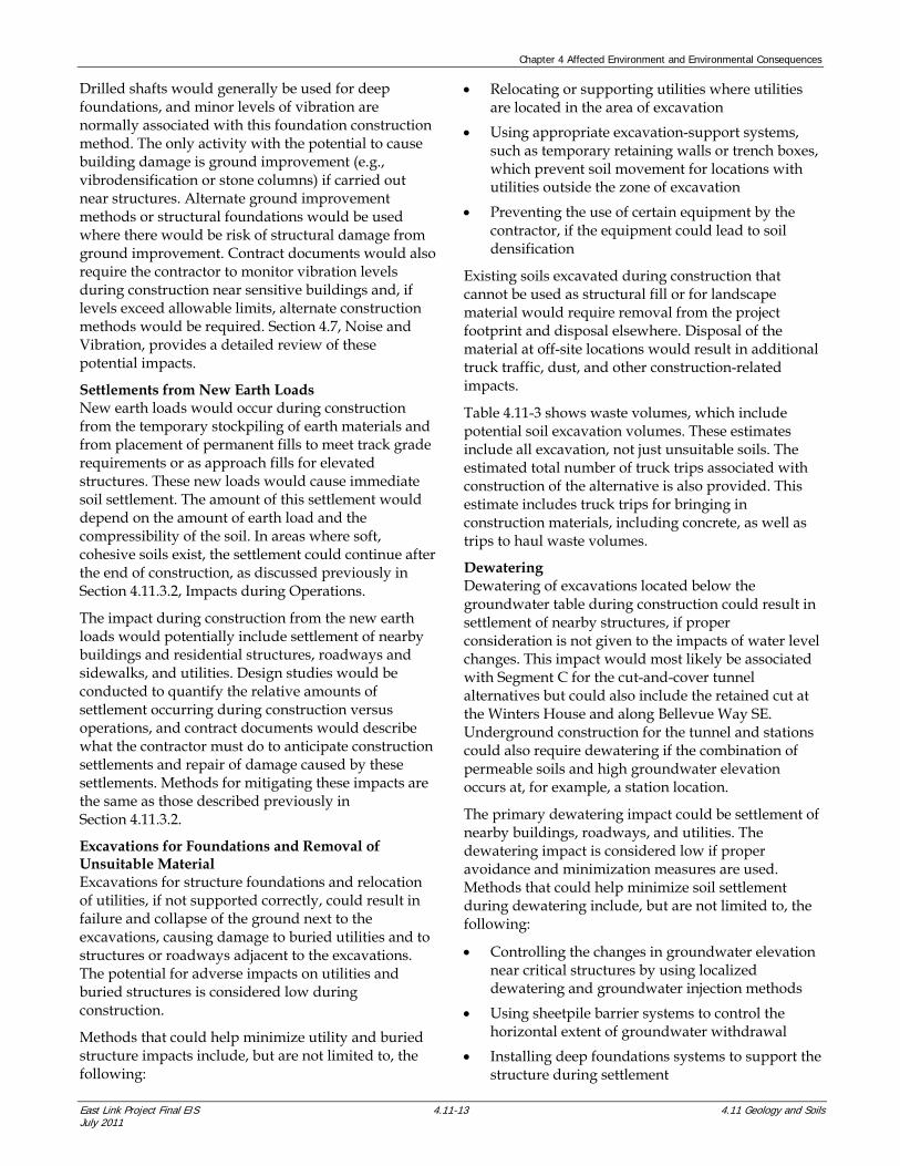
Drilled shafts would generally be used for deep foundations, and minor levels of vibration are normally associated with this foundation construction method. The only activity with the potential to cause building damage is ground improvement (e.g., vibrodensification or stone columns) if carried out near structures. Alternate ground improvement methods or structural foundations would be used where there would be risk of structural damage from ground improvement. Contract documents would also require the contractor to monitor vibration levels during construction near sensitive buildings and, if levels exceed allowable limits, alternate construction methods would be required. Section 4.7, Noise and Vibration, provides a detailed review of these potential impacts.
Settlements from New Earth Loads New earth loads would occur during construction from the temporary stockpiling of earth materials and from placement of permanent fills to meet track grade requirements or as approach fills for elevated structures. These new loads would cause immediate soil settlement. The amount of this settlement would depend on the amount of earth load and the compressibility of the soil. In areas where soft, cohesive soils exist, the settlement could continue after the end of construction, as discussed previously in Section 4.11.3.2, Impacts during Operations.
The impact during construction from the new earth loads would potentially include settlement of nearby buildings and residential structures, roadways and sidewalks, and utilities. Design studies would be conducted to quantify the relative amounts of settlement occurring during construction versus operations, and contract documents would describe what the contractor must do to anticipate construction settlements and repair of damage caused by these settlements. Methods for mitigating these impacts are the same as those described previously in Section 4.11.3.2.
Excavations for Foundations and Removal of Unsuitable Material Excavations for structure foundations and relocation of utilities, if not supported correctly, could result in failure and collapse of the ground next to the excavations, causing damage to buried utilities and to structures or roadways adjacent to the excavations. The potential for adverse impacts on utilities and buried structures is considered low during construction.
Methods that could help minimize utility and buried structure impacts include, but are not limited to, the following:
Relocating or supporting utilities where utilities are located in the area of excavation
Using appropriate excavation-support systems, such as temporary retaining walls or trench boxes, which prevent soil movement for locations with utilities outside the zone of excavation
Preventing the use of certain equipment by the contractor, if the equipment could lead to soil densification
Existing soils excavated during construction that cannot be used as structural fill or for landscape material would require removal from the project footprint and disposal elsewhere. Disposal of the material at off-site locations would result in additional truck traffic, dust, and other construction-related impacts.
Table 4.11-3 shows waste volumes, which include potential soil excavation volumes. These estimates include all excavation, not just unsuitable soils. The estimated total number of truck trips associated with construction of the alternative is also provided. This estimate includes truck trips for bringing in construction materials, including concrete, as well as trips to haul waste volumes.
Dewatering Dewatering of excavations located below the groundwater table during construction could result in settlement of nearby structures, if proper consideration is not given to the impacts of water level changes. This impact would most likely be associated with Segment C for the cut-and-cover tunnel alternatives but could also include the retained cut at the Winters House and along Bellevue Way SE. Underground construction for the tunnel and stations could also require dewatering if the combination of permeable soils and high groundwater elevation occurs at, for example, a station location.
The primary dewatering impact could be settlement of nearby buildings, roadways, and utilities. The dewatering impact is considered low if proper avoidance and minimization measures are used. Methods that could help minimize soil settlement during dewatering include, but are not limited to, the following:
Controlling the changes in groundwater elevation near critical structures by using localized dewatering and groundwater injection methods
Using sheetpile barrier systems to control the horizontal extent of groundwater withdrawal
Installing deep foundations systems to support the structure during settlement

Chapter 4 Affected Environment and Environmental Consequences
4.11 Geology and Soils 4.11-14 East Link Project Final EIS July 2011
TABLE 4.11-3 Estimated Waste Volumes and Truck Trips
Alternative Estimated Soil Waste
(cubic yards) Estimated Total Truck
Trips a
Segment A
Preferred Interstate 90 Alternative (A1) 32,500 11,040
Segment B
Preferred 112th SE Modified Alternative (B2M) to C11A 396,900 67,060
Preferred 112th SE Modified Alternative (B2M) to C9Tb 385,200 68,990
Bellevue Way Alternative (B1) 248,300 34,010
112th SE At-Grade Alternative (B2A) 206,300 32,480
112th SE Elevated Alternative (B2E) 124,100 20,220
112th SE Bypass Alternative (B3) 174,500 28,830
Alternative B3 - 114th Extension Design Option 171,600 34,090
BNSF Alternative (B7) 230,100 30,230
Segment C
Preferred 108th NE At-Grade Alternative (C11A) 310,100 38,270
Preferred 110th NE Tunnel Alternative( C9T)b 802,900 104,230
Bellevue Way Tunnel Alternative (C1T) 1,680,900 211,010
106th NE Tunnel Alternative (C2T) 1,294,300 153,830
108th NE Tunnel Alternative (C3T) 1,031,900 215,560
Couplet Alternative (C4A) 205,700 133,100
112th NE Elevated Alternative (C7E) 165,800 28,530
110th NE Elevated Alternative (C8E) 199,600 128,300
110th Avenue NE At-Grade Alternative (C9A) 187,400 30,610
114th Avenue NE Elevated Alternative (C14E) 468,200 44,720
Segment D
Preferred NE 16th At-Grade Alternative (D2A) 947,700 117,360
Alternative D2A - 120th Station Design Option 808,600 111,280
Alternative D2A - NE 24th Design Option 1,040,000 130,620
NE 16th Elevated Alternative (D2E) 301,000 37,880
NE 20th Alternative (D3) 643,600 76,510
SR 520 Alternative (D5) 274,700 37,990
Segment E
Preferred Marymoor Alternative (E2) 521,300 79,020
Alternative E2 - Redmond Transit Center Station Design Option 647,900 89,390

Chapter 4 Affected Environment and Environmental Consequences
East Link Project Final EIS 4.11-15 4.11 Geology and Soils July 2011
TABLE 4.11-3 CONTINUED Estimated Waste Volumes and Truck Trips
Alternative Estimated Soil Waste
(cubic yards) Estimated Total Truck
Trips a
Redmond Way Alternative (E1) 591,100 82,950
Leary Way Alternative (E4) 560,800 77,930
Maintenance Facilities
116th Maintenance Facility (MF1) 1,365,400 108,000
BNSF Maintenance Facility (MF2) 406,800 32,040
SR 520 Maintenance Facility (MF3) 599,800 47,350
SE Redmond Maintenance Facility (MF5) 193,600 18,430
Note: Quantities assume all excavation would be wasted. Amount that could be used on site would be defined as design proceeds. The volume of waste is only for the currently known quantities. There is a significant amount of material of which the quantity is unknown that is not contained in this calculation. The quantities only include amounts that can reasonably be estimated at this time.
The number of truck trips is based on trips to remove waste soil, trips to import concrete and other construction materials, and miscellaneous construction travel. Actual numbers would vary depending on the types of equipment used by contractor and the amount of material that would be reused on site. a Includes trips for excavated soil, concrete supply, and other construction materials. b Under the C9T - East Main Station Design Option connecting from Preferred Alternative B2M, waste volumes and truck trips associated with the SE 8th Station in Segment B would not occur; instead, a similar waste volume and number of truck trips would be expected for the East Main Station in Segment C. The total waste volume and number of truck trips for these two segments combined would, therefore, be approximately the same as with Preferred Alternatives C9T and B2M.
Summary The severity or frequency of the construction hazard or impact could be avoided or minimized using conventional design and construction methods. Where impacts are identified as being moderate to high, more effort would be required during design to evaluate the severity of the impact and identify an adequate avoidance and minimization method.
The most important geologic hazard during construction would be erosion control, which would need to be appropriately addressed in all segments. Alternatives with steep slopes would require more consideration than relatively flat areas. Some common methods of erosion control include installing silt fences, providing sedimentation ponds, covering soil, and limiting amounts of exposed earth during wet winter months.
Segment A As stated previously in Section 4.11.3.2, Sound Transit anticipates seismic retrofits for some I-90 structures that would be used by East Link. This may include in-water work in Lake Washington to reinforce the existing structures. New construction on I-90 would involve impacts that are common to all build alternatives, such as erosion, slope instability,
construction vibrations, settlement from new earth loads, and excavation for foundations.
Segment B Preferred Alternative B2M would have more erosion hazards, slope stability, settlement, and localized liquefaction issues compared with the alternatives within the median of Bellevue Way SE (Alternatives B1, B2A, and B2E) or Alternative B7.
Soil improvements would have to be conducted at the edge of Mercer Slough; therefore, special construction methods would be required to protect the slough from construction impacts, such as erosion of exposed soil and slope instabilities.
Special consideration will be required for construction impacts near the Winters House. The proximity of the excavation to the Winters House would require vibrations associated with construction to be very low and for rigid lateral support systems to be used to prevent settlement of the Winters House when excavating to the track grade.
The alternatives associated with 112th Avenue SE in Segment B, including Alternatives B2A, B2E, and B3 and the B3 – 114th Design Option, have flatter slopes and would be expected to have fewer erosion and landslide issues during construction than with

Chapter 4 Affected Environment and Environmental Consequences
4.11 Geology and Soils 4.11-16 East Link Project Final EIS July 2011
Alternative B1, where some steep slopes exist. However, there are more locations along 112th Avenue SE (along the Preferred Alternative B2M route) where soils are believed to be generally softer at the ground surface than soils within the median of Bellevue Way SE (along the Alternative B1 route), and these softer soils are more susceptible to construction-related issues in areas where fills are placed or where foundations for elevated structures must be constructed. The potential slope and erosion issues along Bellevue Way SE (along B1 route) would likely be easier to address than soft soil conditions along 112th Avenue SE.
Alternative B3 and the B3 - 114th Design Option cross Sturtevant Creek and would, therefore, traverse additional areas of soft soils and shallow groundwater conditions compared to the other alternatives. Soft soils and shallow groundwater are more susceptible to construction-related issues such as dewatering and settlement.
With Alternative B7, special methods would be required for protecting wetlands during construction. Existing WSDOT I-90 structures would also need to be protected from soil loads caused by construction of work trestles, foundations for elevated structures, and other construction requirements within the slough, including potential loads from altering the flow of peat during annual changes in water level within Lake Washington. Finally, design precautions would be taken to address the steep slopes along the west side of the former BNSF Railway corridor, which could pose a risk to construction and to the public using 118th Avenue SE.
Segment C Tunnel Options Preferred Alternative C9T is a shallow cut-and-cover tunnel. (Tunnel construction methodology is described in Section 2.4.5 of Chapter 2.) This alternative would be shorter than the other tunnel alternatives, thus producing less soil waste and fewer truck trips; however, there could be more construction issues related to excavation support of buildings, potential need for temporary excavation dewatering, construction vibrations, and potential for roadway damage from ground settlement compared to the deep bore tunnels. The three other alternatives that would involve tunneling (Alternatives C1T, C2T, and C3T) would be constructed by various methods, including using a tunnel-boring machine, sequential excavation mining (SEM), and cut-and-cover methods; Tunneling alternatives within Segment C could result
in settlement of the ground above or adjacent to the tunneling work from loss of ground volume. The risk of tunnel-related settlements could include damage to roadways and utilities, residential structures, and buildings.
Loss of ground volume could occur with tunnel boring machines (with Alternative C3T) and SEM (with Alternative C1T under the Bellevue Arts Museum) when the amount of soil removed along the path of the tunnel excavation exceeds the planned diameter of the tunnel, resulting in loose zones or voids in the soil behind the tunnel liner. These voids or loose zones in the soil could progressively migrate upward and eventually result in loss of foundation bearing support for any building, utility, or roadway located above the void or loosened soil. The reduced bearing support could result in settlement of any structure supported on the zone of loosened soil or void. Loss of ground is most often encountered in poorly graded sands and gravels located below groundwater, where flowing or raveling ground conditions can develop. Settlement of ground can also occur with the cut-and-cover method of tunnel construction if tunnel side walls cannot support the earth and nearby building loads during ground excavation, leading to settlement of the ground behind the tunnel walls as the wall deflects into the excavation. Alternative C2T would have the
least potential for settlement because of the denser substrate underlying its route.
The magnitude of acceptable settlement would depend on the type and dimension of the structure but is generally on the order of 1 inch or less. The settlement is greatest above the centerline of a bored tunnel and decreases outward. Typically, the settlement extends horizontally from the tunnel centerline no more than three times the tunnel diameter, which would be approximately 75 to 85 feet. For a cut-and-cover tunnel, the potential for settlement above the centerline is reduced
because of the construction method; however, a potential for settlement would exist behind the tunnel walls. This distance could extend a distance equivalent to the height of the cut-and-cover tunnel, which could be as much as 45 feet. In areas where retained cuts would be used for access to tunnel sections of the alternative, the potential for settlement behind the retaining walls also would exist. Although Alternative C3T would be primarily a bored tunnel, cut-and-cover construction would still be necessary for construction of the Bellevue Transit Center station with this alternative. These potential risks can be minimized by implementing standard design methods and industry
Loss of Ground Volume
Loss of ground volume refers to the amount of excavated soil in excess of the calculated geometry of the tunnel. If a greater volume of material is excavated than is displaced by the tunnel, then this material was lost from around the tunnel, which could create adverse impacts.

Chapter 4 Affected Environment and Environmental Consequences
East Link Project Final EIS 4.11-17 4.11 Geology and Soils July 2011
best practices, including detailed geotechnical explorations and groundwater evaluations.
Additional geotechnical engineering explorations during final design would be used to select specific tunnel construction methods that control the potential for ground settlement. Because of the nature of the glacial soils along the tunnel alternatives, limited settlement is expected during and after construction. However, localized zone of running sands and raveling gravels could be identified during explorations or encountered during tunneling, which could require special tunnel construction methods. These methods would include treating areas of loose soils by permeation or jet grouting, carefully controlling the steering of tunnel machines to avoid overexcavation of the tunnel diameter, monitoring of the volume of excavated material, using ground conditioning systems to prevent ground loss, controlling conveyor discharge of sands and gravels under groundwater pressure, and compaction or consolidation grouting to compensate for lost ground.
Design and construction would also consider the potential impacts of groundwater elevation changes— either temporary or permanent during and after tunnel construction. Groundwater occurs at or above the tunnel horizon for most of the tunnel alternatives; in parts of Downtown Bellevue, artesian groundwater conditions exist, meaning that the groundwater pressure head is above the ground surface. In many areas groundwater is “perched” on fine-grained material, isolating it from recharge sources. These conditions would potentially affect the selection of tunneling methods and could require localized dewatering, which has the potential to cause subsidence or settlement in soft or loose soils. The potential for settlement from dewatering is higher when soils are loose, tunnels are shallower, excavations for stations are deeper, and adjacent building foundations are shallow. Where soil is settlement-prone, measures could be implemented to limit the settlement from groundwater changes to tolerable levels. These measures could include reinjecting water or using impervious cutoff walls to limit the zone of groundwater elevation change.
During construction, adjacent structures and surface areas would be monitored where there is a potential for settlement. Where critical conditions are identified, it may be necessary to underpin buildings to prevent building settlement or to use active wall bracing systems in the case of cut-and-cover tunnels. These active bracing systems would apply bracing forces to the side walls of the cut-and-cover tunnel to adjust for any tendency to deflect into the excavation as earth is
removed in front of the tunnel walls. Prior to and following construction, Sound Transit would conduct detailed inspections of nearby buildings, residences, and utilities to establish conditions before and after construction. Although no damage to structures is anticipated from the tunneling work, any damage that occurs would be repaired.
At-Grade and Elevated Options Preferred Alternative C11A has at-grade, elevated, and retained cut components. Generally good geologic conditions occur along this alternative. Standard construction methods would be used because of the good soils, minimal loading, there would be no deep excavations, and no geologic concerns exist.
For Alternative C4A, relatively standard construction methods would be used because it would be mostly at-grade, and no geologic concerns exist.
Alternatives C7E and C8E both would be elevated systems with at-grade and retained-fill components. Standard construction techniques of retaining walls and compaction methods would be used to address settlement impacts from new earth loads.
The Alternative C9A route, which is similar to the Preferred Alternative C11A route except that it follows 110th Avenue NE instead of 108th Avenue NE, also has geologic conditions similar to C11A.
Alternative C14E would be an entirely elevated system. Standard retaining wall construction techniques and compaction methods would be used to address settlement impacts from new earth loads from retained fills.
Segment D Soils are typically good along the Preferred Alternative D2A route; however, there are some soft soils adjacent to Kelsey Creek and the Kelsey Creek tributaries. Preferred Alternative D2A is elevated across the tributaries to Kelsey Creek, thereby reducing the potential for settlement compared to an at-grade alternative in this area. Retaining walls would be used to retain fills to meet track grade requirements. If the retaining walls are not designed correctly, settlement could occur behind the wall.
The station at 120th would be in a retained cut 20 feet below grade, but subsurface soil conditions are good
Raveling Gravels
Raveling gravels are gravels that have very little fines (clay or silt particles). When excavated, they tend to roll downward to the angle of repose of the material. This is a common problem on exposed slopes, where coarse material progressively moves down the slope.

Chapter 4 Affected Environment and Environmental Consequences
4.11 Geology and Soils 4.11-18 East Link Project Final EIS July 2011
for this type of construction. Retained cuts under the 120th and 124th Avenues NE crossings would also be in subsurface conditions that are suitable for this construction type. Retained cut walls for the 120th Station and for the bridges can be constructed with limited construction vibrations and noise, but the cuts would produce excavated materials that would require removal from the area. Preferred Alternative D2A would be constructed along slopes adjacent to SR 520, which makes construction activities more difficult than constructing on a flat-grade.
There are some locations with artesian conditions along the alternative that would have to be considered during design and construction of the elevated structures foundations; however, methods for accomplishing such construction are available and have been used in the Puget Sound area.
Impacts during construction of the tail track would be limited because the track system is in place and has been used in the past by heavy rail. Soils at the planned location of parking area and the building should have limited impacts, as long as normal BMPs for erosion control are implemented.
The at-grade Alternative D2A – 120th Station Design Option would be less of a risk to construct than Preferred Alternative D2A at the same location because it would not require retaining walls to meet the track grade requirements. The at-grade option also would not produce nearly as much excavated soil that would require removal from the area.
Alternative D2A - NE 24th Design Option would run east down NE 24th Street and then north on 152nd Avenue NE, avoiding some of the slopes adjacent to SR 520.
Alternative D5 appears to have the least amount of risk of the Segment D alternatives for all impact categories, except for the soils along its route, which would have a higher erosion potential along the south side of SR 520 compared to the other Segment D alternatives.
Segment E Preferred Alternative E2 would cross a hillside that has a moderate potential for erosion and slope instability from steep slopes heading into the valley and a low to moderate potential for liquefaction and settlement in the valley. Available information suggests that the Downtown Redmond Station site is underlain by soft soils that would potentially require ground improvement or deep foundations.
Alternative E2 - Redmond Transit Center Design Option would present a slightly higher risk than
Preferred Alternative E2 during construction because of the additional station at Redmond Town Center. However, both the Redmond Town Center Station and the Downtown Redmond Station would be able to use similar, commonly used construction methods.
Alternatives E1 and E4 are in areas of similar geologic and soils conditions to that of Preferred Alternative E2 and the E2 - Redmond Transit Center Design Option, and no distinct differences were identified.
Maintenance Facilities The primary construction impact for the maintenance facilities would be soil erosion, except at the SE Redmond Maintenance Facility.
MF3 would appear to have a low potential for soil erosion.
MF1 has the highest potential for erosion due to soil conditions and the deep cut required for construction and soil conditions.
MF2 has a slightly lower potential for erosion due to the reduced amount of cut and fill required over that of MF1.
MF5 would likely have more foundation engineering design and construction issues than MF1, MF2, and MF3 because the soils that occur at this general area are prone to settlement.
4.11.4 Potential Mitigation Measures During final design, additional geotechnical studies will inform and refine development of construction techniques and mitigation measures to avoid potential impacts and geologic risks during operations. Engineering design standards and BMPs would be used to avoid and minimize potential construction impacts. Based on the review of potential impacts, the design and construction process would address seismic hazards, soft soils, settlement, steep-slope hazards, landslide hazards, erosion and sediment control, vibrations, and groundwater.