41 CONCRETE PAVEMENT REPAIR - Caltrans - · Web viewSubmit HMWM samples 20 days before use. If...
33
Replace section 41 with: 41 CONCRETE PAVEMENT REPAIR 41-1 GENERAL 41-1.01 GENERAL 41-1.01A Summary Section 41-1 includes general specifications for repairing concrete pavement. Dowel bars must comply with section 40-1. 41-1.01B Definitions Reserved 41-1.01C Submittals At least 15 days before delivering fast-setting concrete, polyester resin binder, or bonding agent to the job site, submit the manufacturer’s recommendations, instructions, and MSDS. Notify the Engineer if polyester resin binder will be stored in containers over 55 gallons. 41-1.01D Quality Control and Assurance 41-1.01D(1) General Before using polyester concrete, allow 14 days for sampling and testing of the polyester resin binder. 41-1.01D(2) Reserved 41-1.02 MATERIALS 41-1.02A General Water for washing aggregates, mixing concrete, curing, and coring must comply with section 90-1.02D. Use the minimum amount of water to produce workable concrete and comply with the manufacturer's instructions. 41-1.02B Fast-Setting Concrete Fast-setting concrete must be one of the following: 1. Magnesium phosphate concrete that is either: 1.1. Single component water activated 1.2. Dual component with a prepackaged liquid activator 2. Modified high-alumina based concrete 3. Portland cement based concrete Fast-setting concrete must be stored in a cool and dry environment. If used, the addition of retarders must comply with the manufacturer's instructions. You may use any accelerating chemical admixtures complying with ASTM C494/C494M, Type C and section 90-1.02E.
Transcript of 41 CONCRETE PAVEMENT REPAIR - Caltrans - · Web viewSubmit HMWM samples 20 days before use. If...

Replace section 41 with:41 CONCRETE PAVEMENT REPAIR
41-1 GENERAL41-1.01 GENERAL41-1.01A SummarySection 41-1 includes general specifications for repairing concrete pavement.
Dowel bars must comply with section 40-1.
41-1.01B DefinitionsReserved
41-1.01C SubmittalsAt least 15 days before delivering fast-setting concrete, polyester resin binder, or bonding agent to the job site, submit the manufacturer’s recommendations, instructions, and MSDS. Notify the Engineer if polyester resin binder will be stored in containers over 55 gallons.
41-1.01D Quality Control and Assurance41-1.01D(1) GeneralBefore using polyester concrete, allow 14 days for sampling and testing of the polyester resin binder.
41-1.01D(2) Reserved41-1.02 MATERIALS41-1.02A GeneralWater for washing aggregates, mixing concrete, curing, and coring must comply with section 90-1.02D.
Use the minimum amount of water to produce workable concrete and comply with the manufacturer's instructions.
41-1.02B Fast-Setting ConcreteFast-setting concrete must be one of the following:
1. Magnesium phosphate concrete that is either:1.1. Single component water activated1.2. Dual component with a prepackaged liquid activator
2. Modified high-alumina based concrete3. Portland cement based concrete
Fast-setting concrete must be stored in a cool and dry environment.
If used, the addition of retarders must comply with the manufacturer's instructions.
You may use any accelerating chemical admixtures complying with ASTM C494/C494M, Type C and section 90-1.02E.
Fast-setting concrete properties must have the values shown in the following table:

Fast-Setting ConcreteProperty Test method Value
Compressive strengtha (psi, min)at 3 hoursat 4 hours
California Test 551California Test 551
3,0005,000
Flexural strengtha (psi, min, at 24 hours) California Test 551 500Bond strengtha (psi, min, at 24 hours)
Saturated surface dry concreteDry concrete
California Test 551California Test 551
300400
Water absorption (%, max) California Test 551 10Abrasion resistancea (g, max, at 24 hours) California Test 550 25Drying shrinkage (%, max, at 4 days) ASTM C596 0.13Water soluble chloridesb (%, max, by weight) California Test 422 0.05Water soluble sulfatesb (%, max, by weight) California Test 417 0.25Thermal stability (%, min) California Test 553 90aPerform test with aggregate filler if used.bTest must be performed on a cube specimen, fabricated under California Test 551, cured at least 14 days, and then pulverized to 100% passing the no. 50 sieve.
Aggregate filler may be used to extend prepackaged concrete. Aggregate filler must:
1. Be clean and uniformly rounded.2. Have a moisture content of 0.5-percent by weight or less when tested under California Test 226. 3. Comply with sections 90-1.02C(2) and 90-1.02C(3). 4. Not exceed 50 percent of the concrete volume or the maximum recommended by the fast-setting
concrete manufacturer, whichever is less.
When tested under California Test 202, aggregate filler must comply with the grading in the following table:
Aggregate Filler GradingSieve size Percentage passing3/8 inch 100
No. 4 50–100No. 16 0–5
41-1.02C Polyester ConcretePolyester concrete consists of polyester resin binder and dry aggregate. The polyester resin binder must be an unsaturated isophthalic polyester-styrene copolymer.
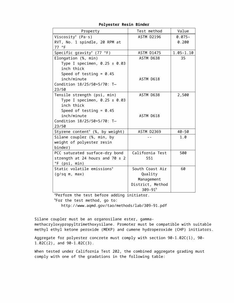
Polyester resin binder properties must have the values shown in the following table:

Polyester Resin BinderProperty Test method Value
Viscositya (Pa·s)RVT, No. 1 spindle, 20 RPM at 77 °F
ASTM D2196 0.075–0.200
Specific gravitya (77 °F) ASTM D1475 1.05–1.10Elongation (%, min)
Type I specimen, 0.25 ± 0.03 inch thickSpeed of testing = 0.45 inch/minute
Condition 18/25/50+5/70: T—23/50
ASTM D638
ASTM D618
35
Tensile strength (psi, min)Type I specimen, 0.25 ± 0.03 inch thickSpeed of testing = 0.45 inch/minute
Condition 18/25/50+5/70: T—23/50
ASTM D638
ASTM D618
2,500
Styrene contenta (%, by weight) ASTM D2369 40–50Silane coupler (%, min, by weight of polyester resin binder)
-- 1.0
PCC saturated surface-dry bond strength at 24 hours and 70 ± 2 °F (psi, min)
California Test 551 500
Static volatile emissionsa (g/sq m, max) South Coast Air Quality Management District,
Method 309-91b
60
aPerform the test before adding initiator.bFor the test method, go to:
http://www.aqmd.gov/tao/methods/lab/309-91.pdf
Silane coupler must be an organosilane ester, gamma-methacryloxypropyltrimethoxysilane. Promoter must be compatible with suitable methyl ethyl ketone peroxide (MEKP) and cumene hydroperoxide (CHP) initiators.
Aggregate for polyester concrete must comply with section 90-1.02C(1), 90-1.02C(2), and 90-1.02C(3).
When tested under California Test 202, the combined aggregate grading must comply with one of the gradations in the following table:
Combined Aggregate GradingSieve size
Percentage passingA B C
1/2" 100 100 1003/8" 83–100 100 100
No. 4 65–82 62–85 45–80No. 8 45–64 45–67 35–67
No. 16 27–48 29–50 25–50No. 30 12–30 16–36 15–36No. 50 6–17 5–20 5–20
No. 100 0–7 0–7 0–9No. 200 0–3 0–3 0–6
Aggregate retained on the no. 8 sieve must have a maximum of 45 percent crushed particles under California Test 205. Fine aggregate must be natural sand.
The weighted average absorption must not exceed 1 percent when tested under California Tests 206 and 207.
You may submit an alternative grading or request to use manufactured sand as fine aggregate but 100 percent of the combined grading must pass the 3/8 inch sieve. Allow 21 days for authorization.
Polyester concrete must have a minimum compressive strength of 1250 psi at 3 hours and 30 minutes under California Test 551 or ASTM C109.
41-1.02D Bonding AgentBonding agent must comply with the concrete manufacturer’s recommendations.
41-1.02E Temporary Pavement StructureTemporary pavement structure consists of RSC or aggregate base with HMA. RSC not conforming to the specifications may serve as temporary pavement structure if:
1. The modulus of rupture is at least 200 psi before opening to traffic2. RSC thickness is greater than or equal to the existing concrete pavement surface layer3. RSC is replaced during the next paving shift
Aggregate base for temporary pavement structure must comply with the 3/4-inch maximum grading specified in section 26-1.02B.
HMA must comply with section 39-1.15 except do not use HMA Type B.
41-1.02F Reserved41-1.03 CONSTRUCTION41-1.03A GeneralRepair only the portion of pavement where the work will be completed during the same lane closure. If removal is required, remove only the portion of pavement where the repair will be completed during the same traffic closure. Completion of concrete repair includes curing until the concrete attains the specified minimum properties required before opening the repaired pavement to traffic.
If you fail to complete the concrete pavement repair during the same lane closure, construct temporary pavement before opening the lane to traffic.
Before starting repair work, except saw cutting: the equipment, materials, and personnel for constructing temporary pavement structure must be at the job site or an approved location. If HMA can be delivered to the job site within 1 hour, you may request 1-hour delivery as an alternative to having the HMA at the job site.
Maintain the temporary pavement structure and replace it as a first order of work as soon as you resume concrete pavement repair work.
After removing temporary pavement structure, you may stockpile that aggregate base at the job site and reuse it for temporary pavement structure.
41-1.03B Mixing and Applying Bonding AgentMix and apply the bonding agent at the job site under the manufacturer's instructions and in small quantities.
Apply bonding agent after cleaning the surface and before placing concrete.
Apply a thin, even coat of bonding agent with a stiff bristle brush until the entire repair surface is scrubbed and coated with bonding agent.
41-1.03C Mixing Concrete41-1.03C(1) GeneralMix concrete in compliance with the manufacturer's instructions. For repairing spalls, mix in a small mobile drum or paddle mixer. Comply with the manufacturer’s recommended limits for the quantity of aggregate filler, water, and liquid activator.
Mix the entire contents of prepackaged dual-component magnesium phosphate concrete as supplied by the manufacturer. Use the full amount of each component and do not add water to dual-component magnesium phosphate concrete.

Magnesium phosphate concrete must not be mixed in containers or worked with tools containing zinc, cadmium, aluminum, or copper.
Modified high-alumina based concrete must not be mixed in containers or worked with tools containing aluminum.
41-1.03C(2) Polyester ConcreteWhen mixing with resin, the moisture content of the combined aggregate must not exceed 1/2 of the average aggregate absorption when tested under California Test 226.
Proportion the polyester resin and aggregate to produce a mixture with suitable workability for the intended work. Only a minimal amount of resin may rise to the surface after finishing.
41-1.03D Placing ConcreteThe pavement surface temperature must be at least 40 degrees F before placing concrete. You may propose methods to heat the surfaces.
Place magnesium phosphate concrete on a dry surface.
Place portland cement and modified high-alumina concrete on surfaces treated with a bonding agent recommended by the concrete manufacturer. If no bonding agent is recommended by the manufacturer, place concrete on damp surfaces that are not saturated.
Do not retemper concrete. Use dry finishing tools cleaned with water before working the concrete.
41-1.03E Curing ConcreteCure concrete under the manufacturer's instructions. When curing compound is used, comply with section 90-1.03B for curing compound no. 1 or 2.
41-1.03F Reserved41-1.04 PAYMENTNot Used
41-2 SUBSEALING AND JACKING41-2.01 GENERAL41-2.01A SummarySection 41-2 includes specifications for filling voids under existing concrete pavement.
41-2.01B DefinitionsReserved
41-2.01C SubmittalsSubmit shipping invoices with packaged or bulk fly ash and cement.
Before grouting activities begin, submit a proposal for the materials to be used. Include authorized laboratory test data for the grout indicating:
1. Time of initial setting under ASTM C266.2. Compressive strength results at 1, 3, and 7 days for 10, 12, and 14-second grout efflux times.
If requesting a substitution of grout materials, submit a proposal that includes test data.
41-2.01D Quality Control and AssuranceReserved
41-2.02 MATERIALS41-2.02A GeneralReserved

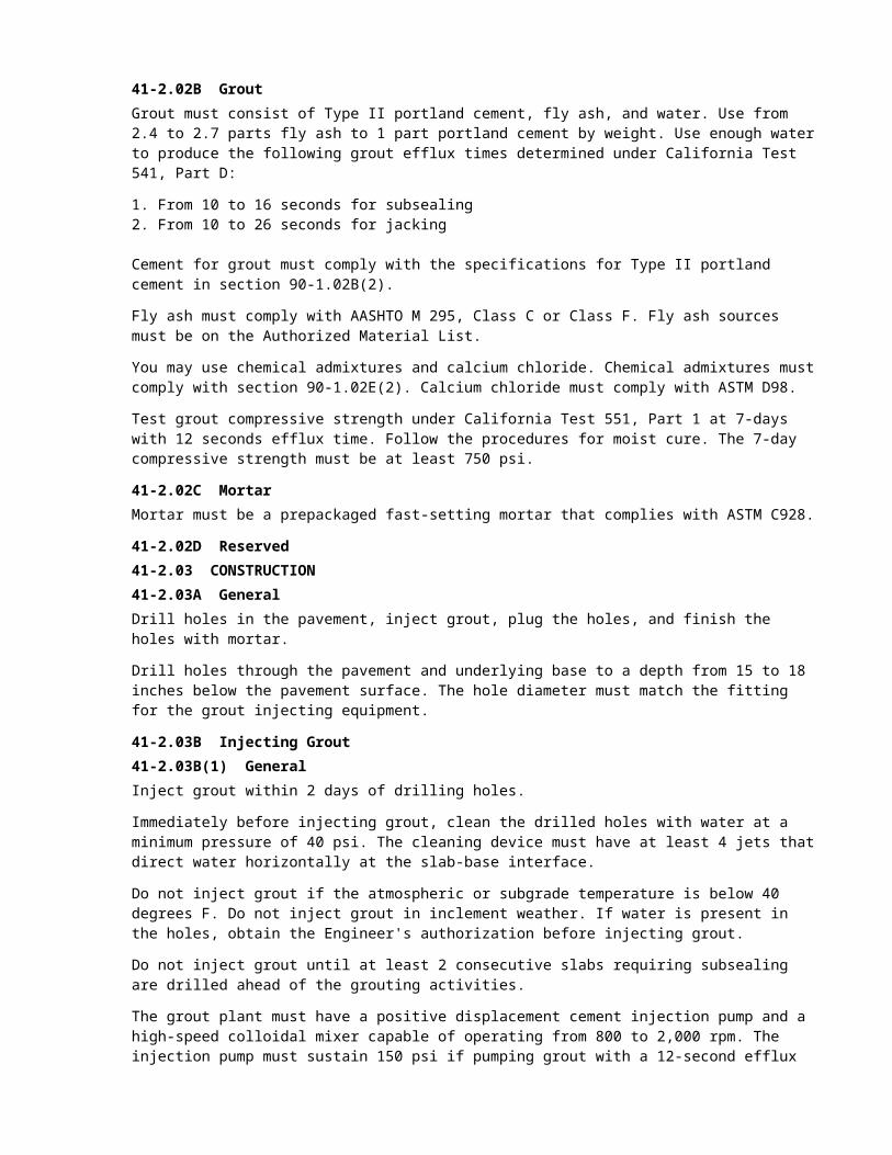
41-2.02B GroutGrout must consist of Type II portland cement, fly ash, and water. Use from 2.4 to 2.7 parts fly ash to 1 part portland cement by weight. Use enough water to produce the following grout efflux times determined under California Test 541, Part D:
1. From 10 to 16 seconds for subsealing2. From 10 to 26 seconds for jacking
Cement for grout must comply with the specifications for Type II portland cement in section 90-1.02B(2).
Fly ash must comply with AASHTO M 295, Class C or Class F. Fly ash sources must be on the Authorized Material List.
You may use chemical admixtures and calcium chloride. Chemical admixtures must comply with section 90-1.02E(2). Calcium chloride must comply with ASTM D98.
Test grout compressive strength under California Test 551, Part 1 at 7-days with 12 seconds efflux time. Follow the procedures for moist cure. The 7-day compressive strength must be at least 750 psi.
41-2.02C MortarMortar must be a prepackaged fast-setting mortar that complies with ASTM C928.
41-2.02D Reserved41-2.03 CONSTRUCTION41-2.03A GeneralDrill holes in the pavement, inject grout, plug the holes, and finish the holes with mortar.
Drill holes through the pavement and underlying base to a depth from 15 to 18 inches below the pavement surface. The hole diameter must match the fitting for the grout injecting equipment.
41-2.03B Injecting Grout41-2.03B(1) GeneralInject grout within 2 days of drilling holes.
Immediately before injecting grout, clean the drilled holes with water at a minimum pressure of 40 psi. The cleaning device must have at least 4 jets that direct water horizontally at the slab-base interface.
Do not inject grout if the atmospheric or subgrade temperature is below 40 degrees F. Do not inject grout in inclement weather. If water is present in the holes, obtain the Engineer's authorization before injecting grout.
Do not inject grout until at least 2 consecutive slabs requiring subsealing are drilled ahead of the grouting activities.
The grout plant must have a positive displacement cement injection pump and a high-speed colloidal mixer capable of operating from 800 to 2,000 rpm. The injection pump must sustain 150 psi if pumping grout with a 12-second efflux time. A pressure gauge must be located immediately adjacent to the supply valve of the grout hose supply valve and positioned for easy monitoring.
Before mixing, weigh dry cement and fly ash if delivered in bulk. If the materials are packaged, each container must weigh the same.
Introduce water to the mixer through a meter or scale.
Inject grout under pressure until the voids under the pavement slab are filled. The injection nozzle must not leak. Do not inject grout if the nozzle is below the bottom of the slab. Inject grout 1 hole at a time.
Stop injecting grout in a hole if either:
1. Grout does not flow under a sustained pump gauge pressure of 150 psi after 7 seconds and there is no indication the slab is moving.
2. Injected grout rises to the surface at any joint or crack, or flows into an adjacent hole.

Dispose of unused grout within 1 hour of mixing.
41-2.03B(2) SubsealingIf a slab raises more than 1/16 inch due to grout injection, stop injecting grout in that hole.
41-2.03B(3) JackingThe positive displacement pump used for grout injection must be able to provide a sustained gauge pressure of 200 psi. Gauge pressures may be from 200 to 600 psi for brief periods to start slab movement.
You may add additional water to initiate pressure injection of grout. Do not reduce the grout efflux time below 10 seconds.
Raise the slabs uniformly. Use string lines to monitor the pavement movement.
Do not move adjacent slabs not specified for pavement jacking. If you move adjacent slabs, correct the grade within the tolerances for final pavement elevation.
41-2.03B(4) FinishingImmediately after removing the injection nozzle, plug the hole with a round, tapered wooden plug. Do not remove plugs until adjacent holes are injected with grout and no grout surfaces through previously injected holes.
After grouting, remove grout from drilled holes at least 4 inches below the pavement surface. Clean holes and fill with mortar. Finish filled holes flush with the pavement surface.
41-2.03B(5) TolerancesThe final pavement elevation must be within 0.01 foot of the required grade. If the final pavement elevation is between 0.01 and 0.10 foot higher than the required grade, grind the noncompliant pavement surface under section 42 to within 0.01 foot of the required grade.
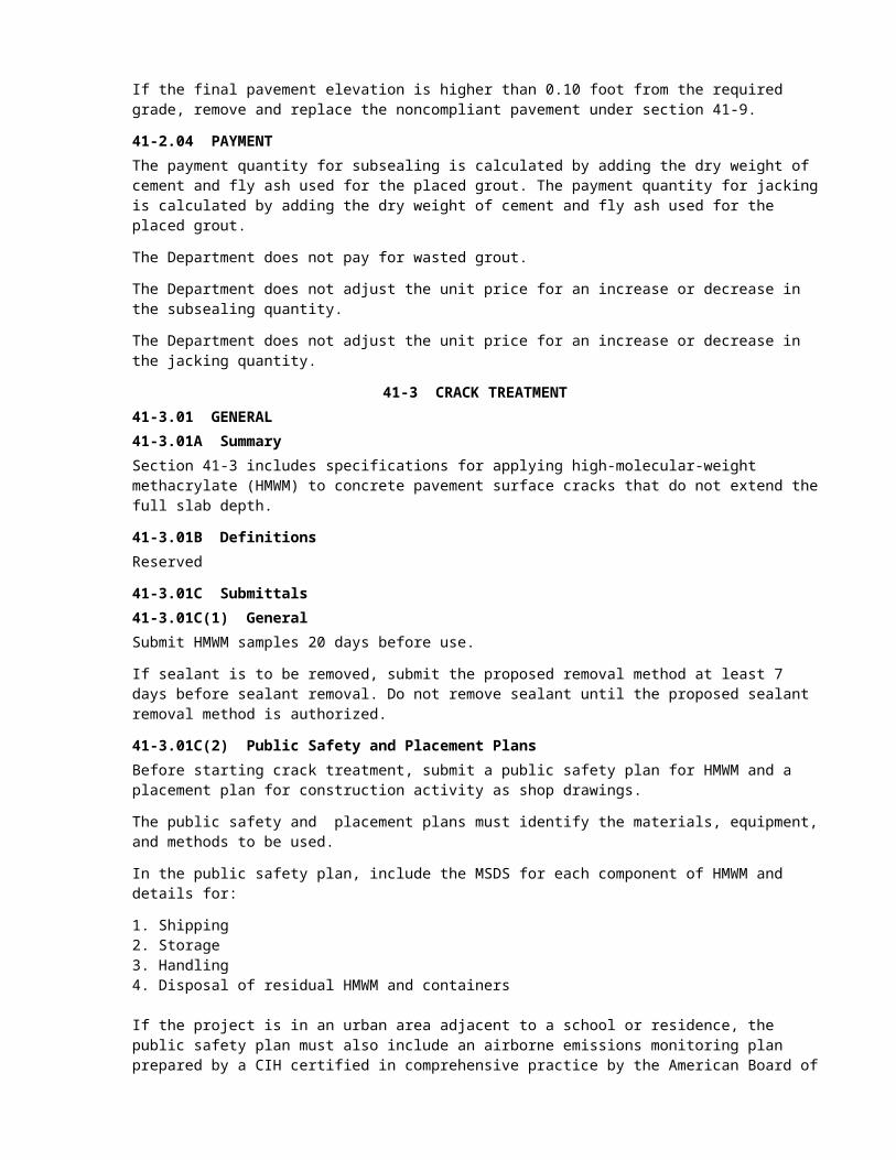
If the final pavement elevation is higher than 0.10 foot from the required grade, remove and replace the noncompliant pavement under section 41-9.
41-2.04 PAYMENTThe payment quantity for subsealing is calculated by adding the dry weight of cement and fly ash used for the placed grout. The payment quantity for jacking is calculated by adding the dry weight of cement and fly ash used for the placed grout.
The Department does not pay for wasted grout.
The Department does not adjust the unit price for an increase or decrease in the subsealing quantity.
The Department does not adjust the unit price for an increase or decrease in the jacking quantity.
41-3 CRACK TREATMENT41-3.01 GENERAL41-3.01A SummarySection 41-3 includes specifications for applying high-molecular-weight methacrylate (HMWM) to concrete pavement surface cracks that do not extend the full slab depth.
41-3.01B DefinitionsReserved
41-3.01C Submittals41-3.01C(1) GeneralSubmit HMWM samples 20 days before use.
If sealant is to be removed, submit the proposed removal method at least 7 days before sealant removal. Do not remove sealant until the proposed sealant removal method is authorized.
41-3.01C(2) Public Safety and Placement PlansBefore starting crack treatment, submit a public safety plan for HMWM and a placement plan for construction activity as shop drawings.
The public safety and placement plans must identify the materials, equipment, and methods to be used.
In the public safety plan, include the MSDS for each component of HMWM and details for:
1. Shipping2. Storage3. Handling4. Disposal of residual HMWM and containers
If the project is in an urban area adjacent to a school or residence, the public safety plan must also include an airborne emissions monitoring plan prepared by a CIH certified in comprehensive practice by the American Board of Industrial Hygiene. Submit a copy of the CIH's certification. The CIH must monitor the emissions at a minimum of 4 points including the mixing point, the application point, and the point of nearest public contact. At work completion, submit a report by the industrial hygienist with results of the airborne emissions monitoring plan.
The placement plan must include:
1. Crack treatment schedule including coefficient of friction testing2. Methods and materials including:
2.1. Description of equipment for applying HMWM2.2. Description of equipment for applying sand2.3. Gel time range and final cure time for resin
Revise rejected plans and resubmit. With each plan rejection, the Engineer gives revision directions including detailed comments in writing. The Engineer notifies you of a plan's acceptance or rejection within 2 weeks of receiving that plan.
41-3.01C(3) Reserved41-3.01D Quality Control and Assurance41-3.01D(1) GeneralUse test tiles to evaluate the HMWM cure time. Coat at least one 4 by 4 inch smooth glazed tile for each batch of HMWM. Place the coated tile adjacent to the area being treated. Do not apply sand to the test tiles.
Use the same type of crack treatment equipment for testing and production.
41-3.01D(2) Test AreaBefore starting crack treatment, treat a test area of at least 500 square feet within the project limits at a location accepted by the Engineer. Use test areas outside the traveled way if available.
Treat the test area under weather and pavement conditions similar to those expected during crack treatment production.
The Engineer evaluates the test area based on the acceptance criteria. Do not begin crack treatment until the Engineer accepts the test area.
41-3.01D(3) Reserved41-3.01D(4) Acceptance CriteriaThe Engineer accepts a treated area if:
1. Corresponding test tiles are dry to the touch2. Treated surface is tack-free and not oily3. Sand cover adheres enough to resist hand brushing4. Excess sand is removed5. Coefficient of friction is at least 0.30 when tested under California Test 342

41-3.02 MATERIALSHMWM consists of compatible resin, promoter, and initiator. HMWM resin may be prepromoted by mixing promoter and resin together before filling containers. Identify prepromoted resin on the container label.
Adjust the gel time to compensate for temperature changes throughout the application.
HMWM resin properties must have the following values:
Property Test method ValueViscosity a (cP, max, Brookfield RVT with UL adapter, 50 RPM at 77 °F)
ASTM D2196 25
Specific gravitya (min, at 77 °F)
ASTM D1475 0.90
Flash point a (°F, min) ASTM D3278 180Vapor pressurea (mm Hg, max, at 77 °F)
ASTM D323 1.0
Tack-free time (minutes, max, at 77 °F)
Specimen prepared under California Test 551
400
Volatile contenta (%, max) ASTM D2369 30PCC saturated surface-dry bond strength (psi, min, at 24 hours and 77 ± 2 °F)
California Test 551 500
aPerform the test before adding initiator.
Sand must be commercial quality dry blast sand. At least 95 percent of the sand must pass the no. 8 sieve and at least 95 percent must be retained on the no. 20 sieve when tested under California Test 202.
41-3.02D Reserved41-3.03 CONSTRUCTION41-3.03A GeneralBefore applying HMWM, clean the pavement surface by abrasive blasting and blow loose material from visible cracks with high-pressure air. Remove concrete curing seals from the pavement to be treated. The pavement must be dry when blast cleaning is performed. If the pavement surface becomes contaminated before applying the HMWM, clean the pavement surface by abrasive blasting.
If performing abrasive blasting within 10 feet of a lane occupied by traffic, operate abrasive blasting equipment with a concurrently operating vacuum attachment.
During pavement treatment, protect pavement joints, working cracks, and surfaces not being treated.
The equipment applying HMWM must combine the components by either static in-line mixers or by external intersecting spray fans. The pump pressure at the spray bars must not cause atomization. Do not use compressed air to produce the spray. Use a shroud to enclose the spray bar apparatus.
You may apply HMWM manually to prevent overspray onto adjacent traffic. If applying resin manually, limit the batch quantity of HMWM to 5 gallons.
Apply HMWM at a rate of 90 square feet per gallon. The prepared area must be dry and the surface temperature must be from 50 to 100 degrees F while applying HMWM. Do not apply HMWM if the ambient relative humidity is more than 90 percent.
Protect existing facilities from HMWM. Repair or replace existing facilities contaminated with HMWM at your expense.
Flood the treatment area with HMWM to penetrate the pavement and cracks. Apply HMWM within 5 minutes after complete mixing. Mixed HMWM viscosity must not increase. Redistribute excess material with squeegees or brooms within 10 minutes of application. Remove excess material from tined grooves.
Wait at least 20 minutes after applying HMWM before applying sand. Apply sand at a rate of approximately 2 pounds per square yard or until refusal. Remove excess sand by vacuuming or sweeping.
Do not allow traffic on the treated surface until:
1. Treated surface is tack-free and non-oily2. Sand cover adheres enough to resist hand brushing3. Excess sand is removed4. Coefficient of friction is at least 0.30 determined under California Test 342
41-3.04 PAYMENTNot Used
41-4 SPALL REPAIR41-4.01 GENERALSection 41-4 includes specifications for repairing spalls in concrete pavement.
41-4.02 MATERIALSRepair spalls using polyester concrete with a bonding agent. The bonding agent must comply with the requirements for HMWM in section 41-3.02 except tack-free time requirements do not apply and the HMWM must not contain wax.
Form board must be corrugated cardboard with a 6-mil polyethylene covering.
41-4.03 CONSTRUCTION41-4.03A GeneralPrepare spall areas by removing concrete and cleaning. Use a form board to provide compression relief at joints and cracks.
After completing spall repairs do not allow traffic on the repairs for at least 2 hours after the time of final setting under ASTM C403/403M.
41-4.03B Remove PavementThe Engineer determines the rectangular limits of unsound concrete pavement. Before removing pavement, mark the saw cut lines and spall repair area on the pavement surface.
Do not remove pavement until the Engineer verbally authorizes the saw cut area.
Use a power-driven saw with a diamond blade.
Remove pavement as shown and:
1. From the center of the repair area towards the saw cut 2. To the full saw cut depth 3. At least 2 inches beyond the saw cut edge to produce a rough angled surface
Produce a rough surface by chipping or other removal methods that do not damage the pavement remaining in-place. Completely remove any saw overcuts. Pneumatic hammers used for concrete removal must weigh 15 lbs or less.
If you damage concrete pavement outside the removal area, enlarge the area to remove the damaged pavement.
If dowel bars are exposed during removal, remove concrete from the exposed surface and cover with duct tape.
41-4.03C CleaningAfter pavement has been removed, clean the exposed faces of the concrete by:
1. Sand or water blasting. Water blasting equipment must be capable of producing a blast pressure of 3,000 to 6,000 psi.

2. Blowing the exposed concrete area with compressed air free of moisture and oil to remove debris after blasting. Air compressors must deliver air at a minimum of 120 cfm and develop 90 psi of nozzle pressure.
41-4.03D Form Board InstallationAfter cleaning, place the form board to match the existing joint or crack alignment. Extend the form board at least 3 inches beyond each end of the repair and at least 1 inch deeper than the repair. Remove the form board before sealing joints or cracks.
41-4.03E–41-4.03I Reserved41-4.04 PAYMENTPayment is calculated based on the authorized saw cut area.
The Department does not adjust the unit price for an increase or decrease in the spall repair quantity.
41-5 JOINT SEALS41-5.01 GENERAL41-5.01A SummarySection 41-5 includes specifications for sealing concrete pavement joints or replacing existing concrete pavement joint seals. Pavement joints include isolation joints.
41-5.01B DefinitionsReserved
41-5.01C SubmittalsAt least 15 days before delivery to the job site, submit a certificate of compliance, MSDS, manufacturer's recommendations, and instructions for storage and installation of:
1. Liquid joint sealant.2. Backer rods. Include the manufacturer data sheet verifying compatibility with the liquid joint sealant.3. Preformed compression joint seal. Include the manufacturer data sheet used to verify the seal for the
joint dimensions shown.4. Lubricant adhesive.
Asphalt rubber joint sealant containers must comply with ASTM D6690. Upon delivery of asphalt rubber joint sealant to the job site, submit a certified test report for each lot based on testing performed within 12 months.
Submit a work plan for removing pavement and joint materials. Allow 10 days for authorization. Include descriptions of the equipment and methods for removal of existing pavement and joint material.
41-5.01D Quality Control and Assurance41-5.01D(1) GeneralBefore sealing joints, arrange for a representative from the manufacturer to provide training on cleaning and preparing the joint and installing the liquid joint sealant or preformed compression joint seal. Do not seal joints until your personnel and the Department's personnel have been trained.
The Engineer accepts joint seals based on constructed dimensions and visual inspection of completed seals for voids.
41-5.01D(2) Reserved41-5.02 MATERIALS41-5.02A GeneralUse the type of seal material described.
Silicone or asphalt rubber joint sealant must not bond or react with the backer rod.
41-5.02B Silicone Joint SealantSilicone joint sealant must be on the Authorized Material List.

41-5.02C Asphalt Rubber Joint SealantAsphalt rubber joint sealant must:
1. Be paving asphalt mixed with not less than 10 percent ground rubber by weight. Ground rubber must be vulcanized or a combination of vulcanized and devulcanized materials that pass a no. 8 sieve.
2. Comply with ASTM D6690 for Type II.3. Be capable of melting at a temperature below 400 degrees F and applied to cracks and joints.
41-5.02D Backer RodsBacker rods must:
1. Comply with ASTM D5249:1.1. Type 1 for asphalt rubber joint sealant 1.2. Type 1 or Type 3 for silicone joint sealant
2. Be expanded, closed-cell polyethylene foam3. Have a diameter at least 25 percent greater than the saw cut joint width
41-5.02E Preformed Compression Joint SealsPreformed compression joint seals must:
1. Comply with ASTM D2628 2. Have 5 or 6 cells, except seals 1/2 inch wide or less may have 4 cells
Lubricant adhesive used to install seals must comply with ASTM D2835.
41-5.02F–41-5.02K Reserved41-5.03 CONSTRUCTION41-5.03A GeneralIf joint sealing is described for new concrete pavement, do not start joint sealing activities until the pavement has been in place for at least 7 days. Seal new concrete pavement joints at least 7 days after concrete pavement placement if shown.
Remove existing pavement and joint material by sawing, rectangular plowing, cutting, or manual labor. Saw cut the reservoir before cleaning the joint. Use a power-driven saw with a diamond blade.
If you damage a portion of the pavement to remain in place, repair the pavement under section 41-4.
41-5.03B Joint Cleaning41-5.03B(1) GeneralClean the joint after removal and any repair is complete before installing joint seal material. Cleaning must be completed no more than 4 hours before installing backer rods, liquid joint seal, or preformed compression seals using the following sequence:
1. Removing debris2. Drying3. Sandblasting4. Air blasting5. Vacuuming
Clean in 1 direction to minimize contamination of surrounding areas.
41-5.03B(2) Removing DebrisRemove debris including dust, dirt, and visible traces of old sealant from the joint after sawing, plowing, cutting, or manual removal. Do not use chemical solvents to wash the joint.
41-5.03B(3) DryingAfter removing debris, allow the reservoir surfaces to dry or remove moisture and dampness at the joint with compressed air that may be moderately hot.

41-5.03B(4) SandblastingAfter the joint is dry, sandblast the reservoir to remove remaining residue using a 1/4-inch diameter nozzle and 90 psi minimum pressure. Do not sandblast straight into the reservoir. Angle the sandblasting nozzle within 1 to 2 inches from the concrete and make at least 1 pass to clean each reservoir face.
41-5.03B(5) Air BlastingAfter sandblasting, air blast the reservoir to remove sand, dirt, and dust 1 hour before sealing the joint. Use compressed air free of oil and moisture delivered at a minimum rate of 120 cfm and 90 psi nozzle pressure.
41-5.03B(6) VacuumingAfter air blasting, use a vacuum sweeper to remove debris and contaminants from the pavement surfaces surrounding the joint.
41-5.03B(7) Reserved41-5.03C Installing Liquid Joint SealantWhere backer rods are shown, place the rods before installing liquid joint sealant. Place backer rods under the manufacturer’s instructions unless otherwise specified. The pavement and reservoir surfaces must be dry and the ambient air temperature must be at least 40 degrees F and above the dew point. The reservoir surface must be free of residue or film. Do not puncture the backer rod.
Immediately after placing the backer rod, install liquid joint sealant under the manufacturer’s instructions unless otherwise specified. Before installing, demonstrate that fresh liquid sealant is ejected from the nozzle free of cooled or cured material. For asphalt rubber joint sealant, the pavement surface temperature must be at least 50 degrees F before installing.
Pump liquid joint sealant through a nozzle sized for the width of the reservoir so that liquid joint sealant is placed directly onto the backer rod. The installer must draw the nozzle toward his body and extrude liquid joint sealant evenly. Liquid joint sealant must maintain continuous contact with the reservoir walls during extrusion.
After placing liquid joint sealant, recess it to the depth shown within 10 minutes of installation and before a skin begins to form.
After each joint is sealed, remove excess liquid joint sealant on the pavement surface. Do not allow traffic over the sealed joints until the liquid joint sealant is set, tack free, and firm enough to prevent embedment of roadway debris.
41-5.03D Installing Preformed Compression Joint SealsInstall preformed compression joint seals using lubricant adhesive as shown and under the manufacturer's instructions.
Install longitudinal seals before transverse seals. Longitudinal seals must be continuous except splicing is allowed at intersections with transverse seals. Transverse seals must be continuous for the entire transverse length of concrete pavement except splices are allowed for widening and staged construction. With a sharp instrument, cut across the longitudinal seal at the intersection with transverse construction joints. If the longitudinal seal does not relax enough to properly install the transverse seal, trim the longitudinal seal to form a tight seal between the 2 joints.
If splicing is authorized, comply with the manufacturer's instructions.
Use a machine specifically designed for preformed compression joint seal installation. The machine must install the seal:
1. To the specified depth2. To make continuous contact with the joint walls3. Without cutting, nicking, or twisting the seal4. Without stretching the seal more than 4 percent
Cut preformed compression joint seal material to the exact length of the pavement joint to be sealed. The Engineer measures this length. After you install the preformed compression joint seal, the Engineer

measures the excess length of material at the joint end. The Engineer divides the excess length by the measured cut length to determine the stretch percentage.
Seals must be compressed from 30 to 50 percent of the joint width when complete in place.
41-5.03E Reserved41-5.04 PAYMENTNot Used
41-6 CRACK AND SEAT41-6.01 GENERAL41-6.01A SummarySection 41-6 includes specifications for cracking, seating, and preparing the surface of existing concrete pavement.
41-6.01B DefinitionsReserved
41-6.01C SubmittalsSubmit each core in a plastic bag or tube for acceptance at the time of sampling. Mark each core with a location description.
41-6.01D Quality Control and Assurance41-6.01D(1) GeneralIf cracking is noncompliant:
1. Stop crack and seat work 2. Modify your equipment and procedures and crack the noncompliant pavement again 3. Construct another test section 4. Take additional core samples to verify compliance5. Construct an inspection strip if the concrete pavement has HMA on the surface
41-6.01D(2) Test SectionThe Engineer determines and marks a test section up to 1000 square feet within the crack and seat area shown. Construct the test section and obtain the Engineer's verbal authorization before starting crack and seat work.
Immediately before cracking the test section, apply water to the pavement surface so that cracking can be readily evaluated. Crack the test section and vary impact energy and striking patterns to verify your procedure.
41-6.01D(3) CoringDrill cores at least 6 inches in diameter under ASTM C42 to verify cracking in the Engineer’s presence. Take at least 2 cores per test section and 1 core per lane mile for each pavement cracking machine used. The Engineer determines the core locations.
41-6.01D(4) Reserved41-6.02 MATERIALS41-6.02A GeneralUse fast-setting or polyester concrete to fill core holes.
41-6.03 CONSTRUCTION41-6.03A CrackingCrack existing concrete pavement using the procedures and equipment from the authorized test section.
Do not allow flying debris during cracking operations.
Crack existing concrete pavement into segments that nominally measure 6 feet transversely by 4 feet longitudinally. If the existing pavement is already cracked into segments, crack it into equal-sized square
or rectangular pieces that nominally measure not more than 6 feet transversely and from 3 to 5 feet longitudinally. Do not impact the pavement within 1 foot of another break line, pavement joint, or edge of pavement.
Cracks must be vertical, continuous, and penetrate the full depth of pavement. Cracks must be within 6 inches of vertical along the full depth of pavement. Do not cause surface spalling over 0.10-foot deep or excessive shattering of the pavement or base.
Cracking equipment must impact the pavement with a variable force in a controlled location. Do not use unguided free-falling weights such as "headache balls."
If the concrete pavement has no more than 0.10 foot of asphalt concrete on the surface, you may crack the pavement without removing the asphalt concrete. After cracking, construct an inspection strip by removing at least 500 square feet of asphalt concrete at a location determined by the Engineer. Construct additional inspection strips to demonstrate compliance where ordered by the Engineer.
After cracking, allow public traffic on the cracked or initial pavement layer for no more than 15 days.
41-6.03B SeatingSeat cracked concrete by making at least 5 passes over the cracked concrete with either:
1. Oscillating pneumatic-tired roller under section 39-3.03 and at least 15 tons2. Vibratory pad-foot roller exerting a dynamic centrifugal force of at least 10 tons
A pass is 1 movement of a roller in either direction at 5 mph or less.
After all segments have been seated, clean loose debris from joints and cracks using compressed air free of moisture and oil.
Reseat any segment of cracked pavement that has not been overlaid within 24 hours of seating.
41-6.03C Surface PreparationBefore opening cracked and seated pavement to traffic or overlaying:
1. Fill joints, cracks, and spalls wider than 3/4 inch and deeper than 1 inch by applying tack coat and placing HMA under section 39-1.15, except use the no. 4 gradation instead of 3/8-inch.
2. Remove all loose debris and sweep the pavement.
41-6.03D Reserved41-6.04 PAYMENTCrack and seat existing concrete pavement is measured from the area of pavement cracked and seated. No deduction is made for existing cracked segments. The Department does not pay for HMA used to fill joints, cracks, and spalls.
41-7 TRANSITION TAPER41-7.01 GENERALSection 41-7 includes specifications for constructing transition tapers in existing pavement.
41-7.02 MATERIALSNot Used
41-7.03 CONSTRUCTIONConstruct transition tapers by either grinding or removing and replacing the existing concrete. Do not allow flying debris during the construction of tapers.
Grinding must comply with section 42.
Replacement concrete must comply with section 41-9 except place concrete to the taper level shown and finish the surface with a coarse broom.

If the transition taper will be overlaid with HMA that is not placed before opening to traffic and there is a grade difference of more than 0.04 foot, construct a temporary taper by placing HMA that complies with section 39-1.15. Remove the temporary HMA taper before constructing the transition taper.
41-7.04 PAYMENTPavement transition tapers are measured using the dimensions shown. The Department does not pay for temporary HMA tapers.
41-8 DOWEL BAR RETROFITReserved
41-9 INDIVIDUAL SLAB REPLACEMENT WITH RAPID STRENGTH CONCRETE41-9.01 GENERAL41-9.01A SummarySection 41-9 includes specifications for removing existing concrete pavement and constructing individual slab replacement with rapid strength concrete (ISR—RSC).
41-9.01B Definitionsconcrete raveling: Disintegration of the concrete surface layer from aggregate loss.
early age: Any age less than 10 times the time of final setting for concrete determined under ASTM C403/C403M.
full-depth crack: Crack that runs from one edge of the concrete slab to the opposite or adjacent side of the slab.
opening age: Age when the minimum modulus of rupture specified for opening to traffic and equipment is attained.
time of final setting: Elapsed time required to develop a concrete penetration resistance that is at least 4,000 psi under ASTM C403/C403M.
41-9.01C Submittals41-9.01C(1) GeneralAt least 15 days before delivery to the job site, submit manufacturer's recommendations, MSDS and instructions for storage and installation of joint filler material.
At least 45 days before starting ISR—RSC work submit a sample of cement from each proposed lot and samples of proposed admixtures in the quantities ordered by the Engineer.
During ISR—RSC placement operations, submit uniformity reports for hydraulic cement at least once every 30 days to the Engineer and METS, attention Cement Laboratory. Uniformity reports must comply with ASTM C917 except testing age and water content may be modified to suit the particular material.
Except for modulus of rupture tests, submit QC test result forms within 48 hours of the paving shift. Submit modulus of rupture results within:
1. 15 minutes of opening age test completion2. 24 hours of 3-day test completion
41-9.01C(2) Quality Control PlanIf the quantity of ISR—RSC is at least 300 cu yd, submit a QC plan at least 20 days before placing trial slabs. If the quantity of ISR—RSC is less than 300 cu yd, submit proposed forms for RSC inspection, sampling, and testing.
41-9.01C(3) Mix DesignAt least 10 days before use in a trial slab, submit a mix design. The maximum ambient temperature range for a mix design is 18 degrees F. Submit more than 1 mix design based on ambient temperature variations anticipated during RSC placement. Each mix design must include:
1. Mix design identification number

2. Aggregate source 3. Opening age4. Aggregate gradation5. Types of cement and chemical admixtures6. Mix proportions7. Maximum time allowed between batching and placing8. Range of effective ambient temperatures9. Time of final setting10. Modulus of rupture development data from laboratory-prepared samples, including tests at:
10.1. 1 hour before opening age10.2. Opening age10.3. 1 hour after opening age10.4. 1 day10.5. 3 days10.6. 7 days10.7. 28 days
11. Shrinkage test data12. Any special instructions or conditions such as water temperature requirements
41-9.01C(4) Reserved41-9.01D Quality Control and Assurance41-9.01D(1) GeneralDesignate a QC manager and assistant QC managers to administer the QC plan. The QC managers must hold current American Concrete Institute (ACI) certification as a Concrete Field Testing Technician-Grade I and a Concrete Laboratory Testing Technician-Grade II, except the assistant QC managers may hold Concrete Laboratory Testing Technician-Grade I instead of Grade II.
The QC manager responsible for the production period involved must review and sign the sampling, inspection, and test reports before submitting them. The QC manager must be present for:
1. Each stage of mix design2. Trial slab construction3. Production and construction of RSC4. Meetings with the Engineer relating to production, placement, or testing
The QC manager must not be a member of this project's production or paving crews, an inspector, or a tester. The QC manager must have no duties during the production and placement of RSC except those specified.
Testing laboratories and equipment must comply with the Department's Independent Assurance Program. At the time of the QC plan submittal, the Department evaluates the quality control samplers and testers.
41-9.01D(2) Just-in-time TrainingReserved
41-9.01D(3) Quality Control PlanEstablish, implement, and maintain a QC plan for pavement The QC plan must describe the organization and procedures used to:
1. Control the production process2. Determine if a change to the production process is needed3. Implement a change
The QC plan must include:
1. Names, qualifications, and certifications of QC personnel, including:1.1. QC manager1.2. Assistant QC managers1.3. Samplers and testers
2. Outline of procedure for the production, transportation, placement, and finishing of RSC

3. Outline of procedure and forms for concrete QC, sampling, and testing to be performed during and after RSC construction, including testing frequencies for modulus of rupture
4. Contingency plan for identifying and correcting problems in production, transportation, placement, or finishing RSC including:4.1. Action limits4.2. Suspension limits that do not exceed specified material requirements4.3. Detailed corrective action if limits are exceeded4.4. Temporary pavement structure provisions, including:
4.4.1. The quantity and location of standby material4.4.2. Determination of need
5. Location of your quality control testing laboratory and testing equipment during and after paving operations
6. List of the testing equipment to be used, including the date of last calibration7. Production target values for material properties that impact concrete quality or strength including
cleanness value and sand equivalent 8. Outline procedure for placing and testing trial slabs, including:
8.1. Locations and times8.2. Production procedures8.3. Placing and finishing methods8.4. Sampling methods, sample curing, and sample transportation8.5. Testing and test result reporting
9. Name of source plant with approved Material Plant Quality Program (MPQP)10. Procedures or methods for controlling pavement quality including:
10.1. Materials quality10.2. Contraction and construction joints10.3. Protecting pavement before opening to traffic
41-9.01D(4) Prepaving ConferenceSchedule a prepaving conference and provide a facility to meet with the Engineer.
Prepaving conference attendees must sign an attendance sheet provided by the Engineer. The prepaving conference must be attended by your:
1. Project superintendent2. Project manager3. QC manager4. Workers and your subcontractor's workers, including:
4.1. Foremen4.2. Concrete plant manager4.3. Concrete plant operator4.4. Concrete plant inspectors4.5. Personnel performing saw cutting and joint sealing4.6. Paving machine operators4.7. Inspectors4.8. Samplers4.9. Testers
The purpose of the prepaving conference is to familiarize personnel with the project's specifications. Discuss the QC plan and processes for constructing each item of work, including:
1. Production2. Transportation3. Trial slabs4. Pavement structure removal5. Placement6. Contingency plan7. Sampling8. Testing9. Acceptance

Do not start trial slabs or paving activities until the listed personnel have attended the prepaving conference.
41-9.01D(5) Trial SlabsBefore starting individual slab replacement work, complete 1 trial slab for each mix design.
Place trial slabs near the job site at a mutually-agreed location that is neither on the roadway nor within the project limits. Trial slabs must be 10 by 20 feet and at least 10 inches thick.
During trial slab construction, sample and split the aggregate for grading, cleanness value, and sand equivalent testing.
Fabricate and test beams under California Test 524 to determine the modulus of rupture values.
Cure beams fabricated for early age testing such that the monitored temperatures in the beams and the slab are always within 5 degrees F of each other.
Monitor and record the internal temperatures of trial slabs and early age beams at intervals of at least 5 minutes. Install thermocouples or thermistors connected to strip-chart recorders or digital data loggers to monitor the temperatures. Temperature recording devices must be accurate to within 2 degrees F. Measure internal temperatures at 1 inch from the top, 1 inch from the bottom, and no closer than 3 inches from any edge until early age testing is completed.
Cure beams fabricated for 3-day testing under California Test 524 except place them into sand at a time that is from 5 to 10 times the time of final setting measured under ASTM C403/403M or 24 hours, whichever is earlier.
Trial slabs must have an opening age modulus of rupture of not less than 400 psi and a 3-day modulus of rupture of not less than 600 psi.
After authorization, remove and dispose of trial slabs and testing materials.
41-9.01D(6) Quality Control Testing41-9.01D(6)(a) GeneralProvide continuous process control and quality control sampling and testing throughout RSC production and placement. Notify the Engineer at least 2 business days notice before any sampling and testing. Establish a testing facility at the job site or at an authorized location.
Sample under California Test 125.
During ISR—RSC placement, sample and fabricate beams for modulus of rupture testing within the first 30 cubic yards, at least once every 130 cu yd, and within the final truckload. Submit split samples and fabricate test beams for the Department’s testing unless the Engineer informs you otherwise.
Determine the modulus of rupture at opening age under California Test 524, except beam specimens may be fabricated using an internal vibrator under ASTM C 31. Cure beams under the same conditions as the pavement until 1 hour before testing. Test 3 beam specimens in the presence of the Engineer and average the results. A single test represents no more than that day's production or 130 cu yd, whichever is less.
Determine the modulus of rupture at other ages using beams cured and tested under California Test 524 except place them in sand from 5 to 10 times the time of final setting under ASTM C403/C403M or 24 hours, whichever is earlier.
41-9.01D(6)(b) Rapid Strength ConcreteYour quality control must include testing RSC for the properties at the frequencies shown in the following table:

RSC Minimum Quality Control Property Test method Minimum testing frequencya
Cleanness value California Test 227 650 cu yd or 1 per shiftSand equivalent California Test 217 650 cu yd or 1 per shiftAggregate gradation California Test 202 650 cu yd or 1 per shiftAir content California Test 504 130 cu yd or 2 per shiftYield California Test 518 2 per shiftSlump or penetration ASTM C143 or California Test 533 1 per 2 hours of pavingUnit weight California Test 518 650 cubic yards or 2 per shiftAggregate Moisture Meter Calibrationb
California Test 223 or California Test 226
1 per shift
Modulus of rupture California Test 524 Comply with section 41-9.01D(6)(a)
aTest at the most frequent interval.bCheck calibration of the plant moisture meter by comparing moisture meter readings with California Test 223 or California Test 226 test results
Maintain control charts to identify potential problems and causes. Post a copy of each control chart at a location determined by the Engineer.
Individual measurement control charts must use the target values in the mix proportions as indicators of central tendency.
Develop linear control charts for:
1. Cleanness value2. Sand equivalent3. Fine and coarse aggregate gradation4. Air content5. Penetration
Control charts must include:
1. Contract number2. Mix proportions3. Test number4. Each test parameter5. Action and suspension limits6. Specification limits7. Quality control test results
For fine and coarse aggregate gradation control charts, record the running average of the previous 4 consecutive gradation tests for each sieve and superimpose the specification limits.
For air content control charts, the action limit is 1.0 percent and the suspension limit is 1.5 percent of the specified values. If no value is specified, apply the air content value used in the approved mix design.
As a minimum, a process is out of control if any of the following occurs:
1. For fine and coarse aggregate gradation, 2 consecutive running averages of 4 tests are outside the specification limits
2. For individual penetration or air content measurements:2.1. One point falls outside the suspension limit line2.2. Two points in a row fall outside the action limit line
Stop production and take corrective action for out of control processes or the Engineer rejects subsequent RSC.
Before each day's concrete pavement placement and at intervals not to exceed 4 hours of production, use a tachometer to test and record vibration frequency for concrete consolidation vibrators.
41-9.01D(6)(c) Reserved41-9.01D(7) Acceptance Criteria41-9.01D(7)(a) GeneralThe final texture of ISR—RSC must pass visual inspection and have a coefficient of friction of at least 0.30 determined under California Test 342.
Allow at least 25 days for the Department to schedule testing for coefficient of friction. Notify the Engineer when the pavement is scheduled to be opened to traffic.
41-9.01D(7)(b) Modulus of RuptureISR—RSC is accepted based on your testing for modulus of rupture at opening age and the Department’s testing for modulus of rupture at 3 days.
ISR—RSC must have a modulus of rupture at opening age that is at least 400 psi and a modulus of rupture at 3 days that is at least 600 psi.
Calculate the test result as the average from testing 3 beams for each sample. The test result represents 1 paving shift or 130 cu yd, whichever is less.
41-9.01D(7)(c) Concrete Pavement SmoothnessThe Department tests for concrete pavement smoothness using a 12-foot straightedge. Straightedge smoothness specifications do not apply to the pavement surface placed within 12 inches of existing concrete pavement except parallel to the centerline at the midpoint of a transverse construction joint.
The concrete pavement surface must not vary from the lower edge of a 12-foot straightedge by more than:
1. 0.01 feet when parallel to the centerline2. 0.02 feet when perpendicular to the centerline extending from edge to edge of a traffic lane
41-9.01D(7)(d) Cracking and RavelingThe Engineer rejects an ISR—RSC slab under section 6-3.06 if within 1 year of contract acceptance there is either:
1. Partial or full-depth cracking2. Concrete raveling consisting of either:
2.1. Combined raveled areas more than 5 percent of each ISR—RSC slab area2.2. Any single raveled area of more than 4 sq ft
41-9.01D(8) Reserved41-9.02 MATERIALS41-9.02A GeneralReserved
41-9.02B Rapid Strength Concrete RSC for ISR—RSC must comply with section 90-3.
Use either the 1-1/2 inch maximum or the 1-inch maximum combined grading specified in section 90-1.02C(4)(d).
Air content must comply with the minimum requirements in section 40-1.02B(4).
41-9.02C Base Bond BreakerUse base bond breaker no. 3, 4, or 5 under section 36-2.

41-9.02D Reserved41-9.03 CONSTRUCTION41-9.03A GeneralComplete ISR—RSC adjacent to new pavement or existing pavement shown for construction as a 1st order of work. Replace individual slabs damaged during construction before placing final pavement delineation.
41-9.03B Removing Existing PavementRemove pavement under section 15-2.02. The Engineer determines the exact ISR—RSC limits after overlying layers are removed.
After removing pavement to the depth shown, grade to a uniform plane. Water as needed and compact the material remaining in place to a firm and stable base. The finished surface of the remaining material must not extend above the grade established by the Engineer.
41-9.03C Drill and Bond Dowel BarsDrill existing concrete and bond dowel bars under section 41-10 if described. Do not install dowel bars in contraction joints.
41-9.03D Base Bond BreakerPlace base bond breaker before placing ISR—RSC. Comply with section 36-2.
41-9.03E Placing Rapid Strength ConcreteDo not place RSC if the ambient air temperature is forecast by the National Weather Service to be less than 40 degrees F within 72 hours of final finishing.
Before placing RSC against existing concrete, place 1/4-inch thick commercial quality polyethylene flexible foam expansion joint filler across the original transverse and longitudinal joint faces and extend the full depth of pavement to the top of the base layer. Place the top of the joint filler flush with the top of the pavement. Secure joint filler to the joint face of the existing pavement to prevent the joint filler from moving during the placement of RSC.
Use metal or wood side forms. Wood side forms must not be less than 1-1/2 inches thick. Side forms and connections must be of sufficient rigidity that movement will not occur under forces from equipment or RSC. Clean and oil side forms before each use. Side forms must remain in place until the pavement edge no longer requires the protection of forms.
After you place RSC, consolidate it using high-frequency internal vibrators adjacent to forms and across the full paving width. Place RSC as nearly as possible to its final position. Do not use vibrators for extensive shifting of concrete pavement.
Spread and shape RSC with powered finishing machines supplemented by hand finishing. After you mix and place RSC, do not add water to the surface to facilitate finishing. You may request authorization to use surface finishing additives. Submit the manufacturer's instructions with your request.
Place consecutive concrete loads without interruption. Do not allow cold joints where a visible lineation forms after concrete is placed, sets, and hardens before additional concrete placed.
Where the existing transverse joint spacing in an adjacent lane exceeds 15 feet, construct an additional transverse contraction joint midway between the existing joints. Complete sawing of contraction joints within 2 hours of completion of final finishing.
Cut contraction joints a minimum of 1/3 the slab depth.
41-9.03F Final FinishingAfter preliminary finishing, round the edges of the initial paving width to a 0.04-foot radius. Round transverse and longitudinal construction joints to a 0.02-foot radius. Mark each ISR—RSC area with a stamp. The stamp mark must show the month, day, and year of placement and contract number. Level the location of the stamp with a steel trowel below the pavement texture. Orient the stamp mark so it can be read from the outside edge of ISR—RSC.

Before curing, texture the pavement. Perform initial texturing with a burlap drag or broom device that produces striations parallel to the centerline. Perform final texturing with a steel-tined device that produces grooves parallel with the centerline.
Tines must be from 3/32 to 1/8 inch wide on 3/4-inch centers and have enough length, thickness, and resilience to form grooves from 1/8 to 3/16 inch deep after the concrete has hardened. Grooves must extend over the entire pavement width except do not construct grooves 3 inches from longitudinal pavement edges or joints.
Final texture must be uniform and smooth. Grooves must be parallel and aligned to the pavement edge across the pavement width. The groove alignment must not vary more than 0.1 foot for every 12 foot length.
Protect RSC under section 90-1.03C.
41-9.03G Temporary Pavement StructureTemporary pavement structure must be RSC or 3-1/2 inch thick HMA over aggregate base.
41-9.03H Noncompliant Individual Slab ReplacementReplace an ISR—RSC slab with any of the following:
1. One or more full-depth cracks.2. Concrete raveling.3. Noncompliant smoothness except you may request authorization for grinding under section 42 and
retesting. Grinding that causes a depression will not be considered. Smoothness must be corrected within 48 hours of placing ISR—RSC.
4. Noncompliant modulus of rupture.
If the modulus of rupture at opening age is at least 400 psi and the modulus of rupture at 3 days is at least 500 psi but less than 600 psi, you may request authorization to leave the ISR—RSC in place and accept the specified deduction.
If pavement is noncompliant for coefficient of friction, groove or grind the pavement under section 42. Comply with section 40-1.03Q(4) and groove or grind before the installation of any required joint seal or edge drains adjacent to the areas to the noncompliant area.
If an ISR—RSC slab has partial depth cracking, treat it with high-molecular-weight methacrylate under section 41-3.
41-9.03I Replace Pavement DelineationReplace traffic stripes, pavement markings, and markers that are removed, obliterated, or damaged by ISR—RSC under sections 84 and 85.
41-9.03J Reserved41-9.04 PAYMENTReplace base is not included in the payment for individual slab replacement (RSC).
Drill and bond dowel bars are not included in payment for individual slab replacement (RSC).
For individual slab replacement (RSC) with a modulus of rupture at opening age that is at least 400 psi and a modulus of rupture at 3 days that is greater than or equal to 500 psi but less than 550 psi, the Department deducts 10 percent of the payment for individual slab replacement (RSC).
For individual slab replacement (RSC) with a modulus of rupture at opening age that is at least 400 psi and a modulus of rupture at 3 days that is greater than or equal to 550 psi but less than 600 psi, the Department deducts 5 percent of the payment for individual slab replacement (RSC).

41-10 DRILL AND BOND BARS41-10.01 GENERAL41-10.01A SummarySection 41-10 includes specifications for drilling, installing, and bonding tie bars and dowel bars in concrete pavement.
41-10.01B DefinitionsReserved
41-10.01C SubmittalsSubmit a certificate of compliance for:
1. Tie bars2. Dowel bars3. Dowel bar lubricant4. Chemical adhesive5. Epoxy powder coating
At least 15 days before delivery to the job site, submit the manufacturer's recommendations and instructions for storage, handling, and use of chemical adhesive.
41-10.01D Quality Control and Assurance41-10.01D(1) GeneralDrill and bond bar is accepted based on inspection before concrete placement.
41-10.01D(2) Reserved41-10.02 MATERIALS41-10.02A GeneralDowel bar lubricant must comply with section 40-1.02D.
Chemical adhesive for drilling and bonding bars must be on the Authorized Material List. The Authorized Material List indicates the appropriate chemical adhesive system for concrete temperature and installation conditions.
Each chemical adhesive system container must clearly and permanently show the following:
1. Manufacturer's name2. Model number of the system3. Manufacture date4. Batch number5. Expiration date6. Current International Conference of Building Officials Evaluation Report number7. Directions for use8. Storage requirement9. Warnings or precautions required by state and federal laws and regulations
41-10.02B Reserved41-10.03 CONSTRUCTION41-10.03A GeneralDrill holes for bars. Clean drilled holes in compliance with the chemical adhesive manufacturer’s instructions. Holes must be dry at the time of placing the chemical adhesive and bars. Use a grout retention ring when drilling and bonding dowel bars. Immediately after inserting the bar into the chemical adhesive, support the bar to prevent movement until chemical adhesive has cured the minimum time recommended by the manufacturer.
Apply dowel bar lubricant to the entire exposed portion of the dowel bar.
If the Engineer rejects a bar installation: stop paving, drilling, and bonding activities. Adjust your procedures and obtain the Engineer's verbal authorization before resuming paving, drilling, and bonding.

Cut the rejected bar flush with the pavement joint surface and coat the exposed end of the bar with chemical adhesive. Offset the new hole 3 inches horizontally from the rejected hole’s center.
41-10.03B Tie Bar TolerancePlace tie bars within the tolerances shown in the following table:
Tie Bar TolerancesDimension Tolerance
Horizontal skew (vertical skew: bar length) 1:6Vertical skew (vertical skew: bar length) 1:6Longitudinal translation (inch) ±1Horizontal offset (embedment, inch) ±1Height relative to the adjacent bar ±1Vertical Depth (clearance from the pavement surface or bottom, inches, min)
3
41-10.03C Dowel Bar TolerancePlace dowel bars within the tolerances specified in section 40-1.01D(7)(b)(v).
41-10.03D Reserved41-10.04 PAYMENTNot Used
41-11–41-15 RESERVED