40NH32A* Contactor - Siemens · The Contactor can also be controlled by separate logic control...
6
13 21 22 14 A1 A2 1L2 3L2 5L3 2T1 4T2 6T3 43 31 32 44 A1 X5 A2 1L2 3L2 5L3 2T1 4T2 6T3 13 21 22 14 1L1 3L2 5L3 2T1 4T2 6T3 31 43 44 32 13 21 22 14 1L1 3L2 5L3 2T1 4T2 6T3 A2 A1 13 21 22 14 1 2 3 X5 Pos. 4 Pos. 3 Pos. 2 Pos. 1 Pos. 5 30° 30° Pos 1 ± 30° A1 A2 M 3,5 ø 5 Pozidriv N° 2 2 x 1 ................... 2,5 mm 2 x 0,75 ............. 2,5 mm 2 2 / > 3,5 mm, L < 8 mm L / Max.50mm Max. 52mm 45 Nm - 398 lb.in M12 SFOI-40070-1204, 1(6), ed.1, January 2005 A2 A1 1 2 3 X5 X5 Enclosure with min. 48 by 36 by 16 inches should be used and secured by at least three latches. After a short circuit, ensure that the quarter turn screws are in the right position. 1 Nm - 9 lb.in According to UL 508: Use wire Cu 75 C only. 40NH32A* Contactor Operating instructions Betriebsanleitung Notice d’instructions Instruktion Istruzioni tecniche IInstrucciones de empleo Ohje Contactors Schtze Contacteurs Kontaktorer Contattori Contactores Kontaktori Warning! The operation, installation and servicing of this product must be carried out by a qualified electrician, following installation standards and safety regulations. Before operating the contactor, make sure that the control voltage supply corresponds with the coil marking. Wrong control voltage can damage the coil. Do not touch live parts. Danger! Warnung! Die inbetriebnahme und die installation des vorhandenen Gerätes sowie jegliche Wartungsarbeiten müssen durch einen Fachelektriker, der die anerkannten technischen Regeln, die Montagenormen und die Sicherheitsvorschriften beachtet, durchgefürt werden. Vor Inbetriebnahme der Schüttze prüfen ob Steuerspannung am Verwendungsort mit den aufgedruckten Spulendaten übereinstimmt. Der Anschluss einer anderen Steuerspannung kan zur Zerstörung der Spule führen. Spannung führende Teile nicht berühren. Lebensgefahr! Attention! La mise en ceuvre et I'installation de cet appareil et toute intervention doivent être affectuées par un électricien professionnel appliquant les normes d'installation et les réglements de sécurité. Avant la mise en marche des contacteurs, vérifier que la tension du circuit de contrôle correspond bien aux indications de la bobine. Le raccordement d'une tension différente peut mener à une destruction de la bobine. Ne pas toucher les pièces sous tension. Danger de mort! Varning! Igångsättning och installation av apparaten samt alla ingrepp bör utföras av en kompetent elektriker enligt alla gällande installationsnormer och säkerhetsregler. Kontrollera före installation av kontaktorn att aktuell manöverspänning överensstämmer med spolens märkdata. Felaktig manöverspänning kan skada spolen. Beröring av spänningsförande delar är förenat med livsfara. Attenzione! La messa in opera, I'installazione di questo apparecchio ed ogni tipo di intervento devona essere effettuati da un elettricista professionista il quale applichi le regole del mestiere, le norme di installazioneed i regolamenti di sicuezza. Prima della messa in servizio del contattore, verificare che la tensione del circuito di comando corrisponda esattamente a quella indicata sulla bobina. L'alimentazione con una tensione diversa, puo provocare la distruzione della bobina. Non toccare le parti attive. Pericole de vita! Atención! La puesta en aplicación, la instalación de este aparato y cualquier intervención deben realizarse por un electricista profesional que aplique las reglas del oficio las normas de instalaciones y la reglamentación de seguridad. Antes de la puesta en servicio del contactor, comprobar si coinciden la tensión de mando con los datos impresos en la bobina. La conexión de otra tensión de mando puede producir la destruccion de la bobina. Las partes bajo tensión no deben tocarse. Peligro de muerte!
Transcript of 40NH32A* Contactor - Siemens · The Contactor can also be controlled by separate logic control...

13
21
22
14
A1 A2
1L2 3L2 5L3
2T1 4T2 6T3
43
31
32
44
A1X5
A2
1L2 3L2 5L3
2T1 4T2 6T3
13
21
22
14
1L1 3L2 5L3
2T1 4T2 6T3
31 43
4432
13 21
2214
1L1 3L2 5L3
2T1 4T2 6T3A2
A113 21
2214
123
X5
Pos. 4 Pos. 3
Pos. 2
Pos. 1
Pos. 5
30°30°
Pos 1 ± 30°
A1
A2
M 3,5 ø 5 Pozidriv N° 22 x 1 ................... 2,5 mm
2 x 0,75 ............. 2,5 mm2
2
/ > 3,5 mm, L < 8 mm
L/
Max.50mmMax. 52mm
45 Nm - 398 lb.in
M12
SFOI-40070-1204, 1(6), ed.1, January 2005
A2
A1
123
X5
X5
Enclosure with min. 48 by 36 by 16 inches should be used and secured by at least three latches. After a short circuit, ensure that the quarter turn screws are in the right position.
1 Nm - 9 lb.in
According to UL 508: Use wire Cu 75 C only.
40NH32A* ContactorOperating instructionsBetriebsanleitungNotice d’instructionsInstruktionIstruzioni tecnicheIInstrucciones de empleoOhje
ContactorsSchtzeContacteursKontaktorerContattoriContactoresKontaktori
Warning! The operation, installation and servicing of this product must be carried out by a qualified electrician, following installation standards and safety regulations. Before operating the contactor, make sure that the control voltage supply corresponds with the coil marking. Wrong control voltage can damage the coil. Do not touch live parts. Danger! Warnung! Die inbetriebnahme und die installation des vorhandenen Gerätes sowie jegliche Wartungsarbeiten müssen durch einen Fachelektriker, der die anerkannten technischen Regeln, die Montagenormen und die Sicherheitsvorschriften beachtet, durchgefürt werden. Vor Inbetriebnahme der Schüttze prüfen ob Steuerspannung am Verwendungsort mit den aufgedruckten Spulendaten übereinstimmt. Der Anschluss einer anderen Steuerspannung kan zur Zerstörung der Spule führen. Spannung führende Teile nicht berühren. Lebensgefahr! Attention! La mise en ceuvre et I'installation de cet appareil et toute intervention doivent être affectuées par un électricien professionnel appliquant les normes d'installation et les réglements de sécurité. Avant la mise en marche des contacteurs, vérifier que la tension du circuit de contrôle correspond bien aux indications de la bobine. Le raccordement d'une tension différente peut mener à une destruction de la bobine. Ne pas toucher les pièces sous tension. Danger de mort! Varning! Igångsättning och installation av apparaten samt alla ingrepp bör utföras av en kompetent elektriker enligt alla gällande installationsnormer och säkerhetsregler. Kontrollera före installation av kontaktorn att aktuell manöverspänning överensstämmer med spolens märkdata. Felaktig manöverspänning kan skada spolen. Beröring av spänningsförande delar är förenat med livsfara. Attenzione! La messa in opera, I'installazione di questo apparecchio ed ogni tipo di intervento devona essere effettuati da un elettricista professionista il quale applichi le regole del mestiere, le norme di installazioneed i regolamenti di sicuezza. Prima della messa in servizio del contattore, verificare che la tensione del circuito di comando corrisponda esattamente a quella indicata sulla bobina. L'alimentazione con una tensione diversa, puo provocare la distruzione della bobina. Non toccare le parti attive. Pericole de vita! Atención! La puesta en aplicación, la instalación de este aparato y cualquier intervención deben realizarse por un electricista profesional que aplique las reglas del oficio las normas de instalaciones y la reglamentación de seguridad. Antes de la puesta en servicio del contactor, comprobar si coinciden la tensión de mando con los datos impresos en la bobina. La conexión de otra tensión de mando puede producir la destruccion de la bobina. Las partes bajo tensión no deben tocarse. Peligro de muerte!
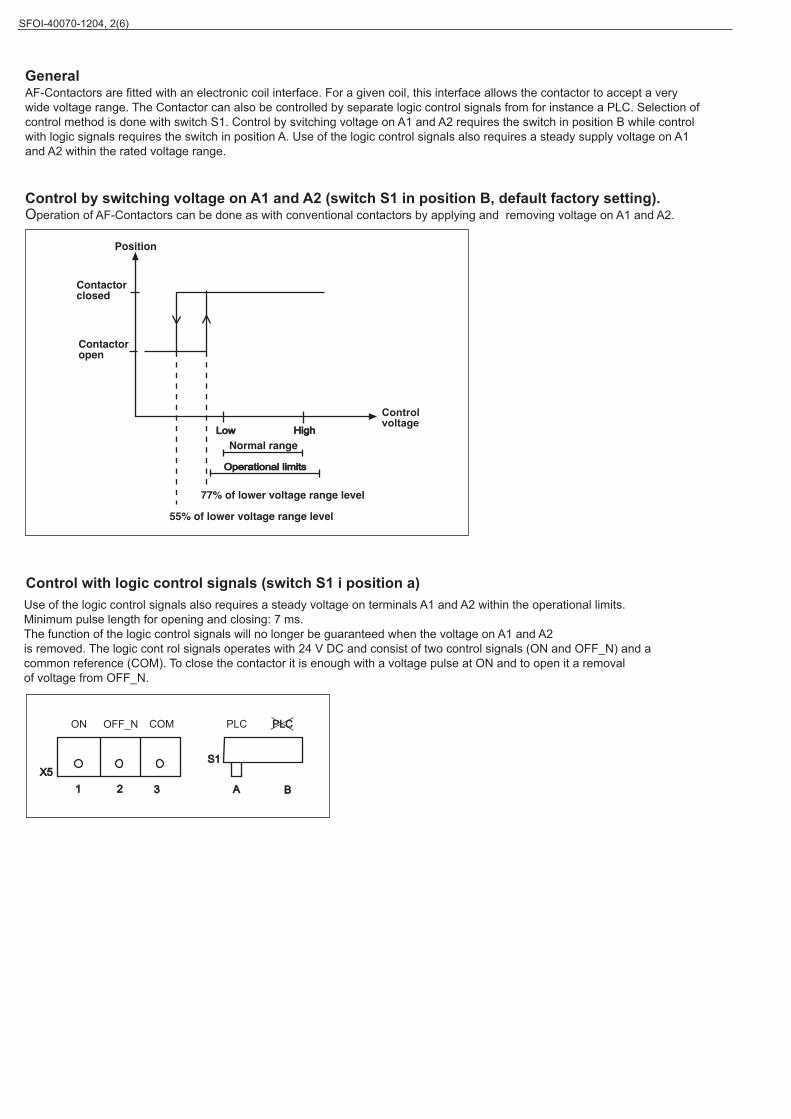
GeneralAF-Contactors are fitted with an electronic coil interface. For a given coil, this interface allows the contactor to accept a verywide voltage range. The Contactor can also be controlled by separate logic control signals from for instance a PLC. Selection ofcontrol method is done with switch S1. Control by svitching voltage on A1 and A2 requires the switch in position B while controlwith logic signals requires the switch in position A. Use of the logic control signals also requires a steady supply voltage on A1and A2 within the rated voltage range.
Control by switching voltage on A1 and A2 (switch S1 in position B, default factory setting).Operation of AF-Contactors can be done as with conventional contactors by applying and removing voltage on A1 and A2.
Low
Operational limits
Control with logic control signals (switch S1 i position a)
High
X51 2 3
S1
A B
Use of the logic control signals also requires a steady voltage on terminals A1 and A2 within the operational limits.Minimum pulse length for opening and closing: 7 ms.The function of the logic control signals will no longer be guaranteed when the voltage on A1 and A2is removed. The logic cont rol signals operates with 24 V DC and consist of two control signals (ON and OFF_N) and acommon reference (COM). To close the contactor it is enough with a voltage pulse at ON and to open it a removalof voltage from OFF_N.
ON OFF_N COM PLC PLC
Controlvoltage
SFOI-40070-1204, 2(6)

Relay
1X5
2
3
When used with switches the wiring can be done according to the following diagram.
When used with transistor outputs the wiring can be done according to the following diagram.
1X5
2
3
24V DC Signals:Status "1" : U=15...33V DC I =10mA at 24V DCStatus "0" : U=0...5V DC
Note: Emergency stop should disconnect A1 and A2 Note: Emergency stop should disconnect A1 and A2
Supply voltage on A1 and A2
1
0ON
OFF_N
Closed
OpenPosition
1
0
1
0
The functions are descibed with following diagram. "1" means 24 V DC between the control signal and COM, "0" means novoltage between the control signal and COM. The function is made so that ON and OFF_N can be connected in parallel fora common ON/OFF signal. In addition to these signals the function limits for the supply voltage are still valid (closing at 77%and opening at 55%), which is indicated in the diagram by high and low voltage.
AF-Contactors comply with international standards IEC 947-1, 947-4-1 and European standards EN 60 947-4-1.Moreover, in environment 2, they meet the electromagnetic compability rules (EMC):Using these materials in environment 1 may lead to radio-interferences requiring the use of additional mitigation methods.Here are the definitions given in the above mentioned standards.Environment 1: "Mainly relates to low-voltage public networks such as residential, commercial and light industriallocations/installations. Highly distributing sources such as arc welders are not covered by this environment".Environment 2: "Mainly relates to low-voltage industrial networks/locations/installations including highly disturbing sources" .
A1
Supply voltage
Contactor
Relay
A1 A2A2
ON
OFF_N
COM
ON
OFF_N
COM
95
9696
95
SFOI-40070-1204, 3(6)
Start
Stop
+24 V+24 V
Start
Stop_n
0V
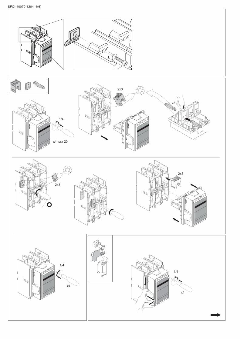
1/4
x4 torx 20
2x3
1/4
x4
2x3
SFOI-40070-1204, 4(6)
x3
2x3
1/4
x4
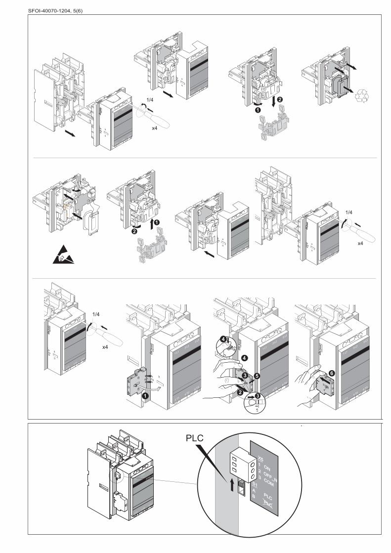
1/4
x4
SFOI-40070-1204, 5(6)
1
1
2
2
x4
1/4
6
Lift
2
Lift
Lift
3
3 5
2
4
4
1
1/4
x4
S1AB
OFF_N
X51
32
ON
COM
PLCPLC
PLC
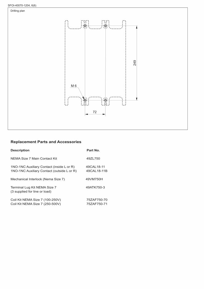
M 6
72
249
Replacement Parts and Accessories
Description Part No.
NEMA Size 7 Main Contact Kit 49ZL750
1NO-1NC Auxiliary Contact (inside L or R) 49CAL18-111NO-1NC Auxiliary Contact (outside L or R) 49CAL18-11B
Mechanical Interlock (Nema Size 7) 49VM750H
Terminal Lug Kit NEMA Size 7 49ATK750-3(3 supplied for line or load)
Coil Kit NEMA Size 7 (100-250V) 75ZAF750-70Coil Kit NEMA Size 7 (250-500V) 75ZAF750-71
SFOI-40070-1204, 6(6)
Drilling plan