405/405HD, 420HD, 430HD, 440HD IP Phones · 15.1.1 Configuring Manual VLAN Assignment to the Phone...
354
Administrator's Manual AudioCodes High Definition IP Phones Series 405/405HD, 420HD, 430HD, 440HD IP Phones Version 2.2.16
Transcript of 405/405HD, 420HD, 430HD, 440HD IP Phones · 15.1.1 Configuring Manual VLAN Assignment to the Phone...

Administrator's Manual
AudioCodes High Definition IP Phones Series
405/405HD, 420HD, 430HD, 440HD IP Phones
Version 2.2.16


Administrator's Manual Contents
Version 2.2.16 3 400HD Series IP Phones
Table of Contents 1 Introduction ....................................................................................................... 19
Configuration Tools................................................................................................ 21
2 IP Phone User Interface .................................................................................... 23
2.1 Accessing the Administration Menu ...................................................................... 23 2.2 Changing Display Language ................................................................................. 24
3 Web Interface ..................................................................................................... 25
3.1 Accessing Web Interface ...................................................................................... 25 3.2 Getting Started with the Web ................................................................................ 26 3.3 Configuring the Web Interface's Port .................................................................... 27 3.4 Configuring User Login Credentials ...................................................................... 27
4 Configuration File.............................................................................................. 29
4.1 Introduction........................................................................................................... 29 4.2 File Syntax ........................................................................................................... 29 4.3 Linking Multiple Files ............................................................................................ 29 4.4 Downloading the Configuration File from the Phone ............................................. 30 4.5 Creating Configuration Files using VoIProvision Utility ......................................... 30
4.5.1 Configuration File Format .................................................................................... 30 4.5.2 Global Configuration File ..................................................................................... 30 4.5.3 VoIProvision Utility Overview ............................................................................... 31 4.5.4 CSV File .............................................................................................................. 31 4.5.5 Template File ...................................................................................................... 31 4.5.6 Generated Configuration Files ............................................................................. 31 4.5.7 Starting the VoIProvision Utility ............................................................................ 32 4.5.8 Usage ................................................................................................................. 32
4.6 Using the Encryption Tool..................................................................................... 32 4.6.1 Encrypting Configuration Files ............................................................................. 32 4.6.2 Encrypting Passwords in the Configuration File ................................................... 33
5 IP Phone Manager Pro ...................................................................................... 35
Automatic Provisioning ......................................................................................... 37
6 Introduction ....................................................................................................... 39
7 Updating the Configuration File Manually ...................................................... 41
8 Setting up Network for Auto Provisioning ...................................................... 43
9 Obtaining Firmware and Configuration Files .................................................. 45
9.1 Provisioning Hunt Order ....................................................................................... 45 9.2 Dynamic URL Provisioning ................................................................................... 45
9.2.1 Provisioning using DHCP Option 160................................................................... 48 9.2.2 Technician's Digit Key Code ................................................................................ 49 9.2.3 Provisioning using DHCP Option 66/67 ................................................................ 50 9.2.4 Provisioning using DHCP Option 43 .................................................................... 50 9.2.5 Provisioning using the User-Class Option ............................................................ 51 9.2.6 SIP SUBSCRIBE and NOTIFY Messages ............................................................ 59

400HD Series IP Phones
Administrator's Manual 4 Document #: LTRT-11957
9.2.7 Hardcoded Domain Name for Provisioning Server ............................................... 61 9.2.8 Cached Address of Last Provisioning Server Used .............................................. 61 9.2.9 Redirect Server ................................................................................................... 62
9.3 Static URL Provisioning ........................................................................................ 63
Quick Setup ............................................................................................................. 65
10 Quick Setup ....................................................................................................... 67
Networking .............................................................................................................. 69
11 Introduction ....................................................................................................... 71
12 Configuring Date and Time Manually .............................................................. 73
12.1 Configuring Daylight Saving Time ......................................................................... 74 12.2 Configuring the NTP Server .................................................................................. 77 12.3 Configuring NTP Server via DHCP ....................................................................... 79
13 Configuring IP Network Settings ..................................................................... 81
13.1 Configuring Static IP Address ............................................................................... 81 13.1.1 Configuring Static IP Address on the Phone ........................................................ 81 13.1.2 Configuring IP Network Settings .......................................................................... 82
13.2 Configuring Partial DHCP ..................................................................................... 84
14 Configuring LAN and PC Port Settings ........................................................... 87
15 Configuring VLAN Settings .............................................................................. 89
15.1 Configuring Manual or Automatic VLAN Assignment ............................................ 90 15.1.1 Configuring Manual VLAN Assignment to the Phone............................................ 90 15.1.2 Configuring Automatic VLAN Assignment to the Phone........................................ 90 15.1.3 Configuring VLAN via DHCP Provisioning Path ................................................... 90
VoIP Settings .......................................................................................................... 91
16 Configuring SIP Settings .................................................................................. 93
16.1 Configuring General SIP Settings ......................................................................... 93 16.2 Configuring Proxy and Registration ...................................................................... 97
16.2.1 Configuring Proxy Redundancy ......................................................................... 100 16.2.2 Device Registration Failover/Failback ................................................................ 103
16.2.2.1 Failover .............................................................................................. 103 16.2.2.2 Failback .............................................................................................. 104
16.3 Configuring a Line .............................................................................................. 105 16.4 Configuring Shared Call Appearance.................................................................. 106 16.5 Configuring SIP Timers ...................................................................................... 107 16.6 Configuring SIP QoS .......................................................................................... 109 16.7 Configuring SIP Reject Code .............................................................................. 110
17 Configuring Dialing ......................................................................................... 111
17.1 Configuring Voice Dialing through VocaNOM ..................................................... 111 17.2 Configuring General Dialing Parameters ............................................................ 112 17.3 Configuring Auto Redial ...................................................................................... 114

Administrator's Manual Contents
Version 2.2.16 5 400HD Series IP Phones
17.4 Configuring Dial Tones ....................................................................................... 115 17.5 Configuring DTMF .............................................................................................. 117 17.6 Configuring Digit Maps and Dial Plans................................................................ 118 17.7 Configuring Headset LED to Stay On ................................................................. 120 17.8 Configuring Default Audio Device ....................................................................... 121
18 Configuring Ring Tones ................................................................................. 123
18.1 Configuring Distinctive Ring Tones ..................................................................... 123 18.1.1 Example of Configuring a Distinctive Ring .......................................................... 124
18.2 Configuring CPT Regional Settings .................................................................... 125 18.3 Uploading Ring Tones ........................................................................................ 127 18.4 Configuring Beeps to Headsets when a Call Comes in to a Call Center ............. 128 18.5 Configuring the Phone to play Fast Busy Tone if Automatically Disconnected on Remote Side....................................................................................................... 129
19 Configuring Media Settings ............................................................................ 131
19.1 Configuring Media Streaming ............................................................................. 131 19.2 Configuring RTP Port Range and Payload Type ................................................. 132 19.3 Configuring RTP QoS ......................................................................................... 133 19.4 Configuring Codecs ............................................................................................ 134 19.5 Configuring OPUS Management ........................................................................ 136
20 Configuring Voice Settings ............................................................................ 137
20.1 Configuring Gain Control .................................................................................... 137 20.2 Configuring Jitter Buffer ...................................................................................... 137 20.3 Configuring Silence Compression ....................................................................... 138 20.4 Configuring Noise Reduction .............................................................................. 139 20.5 Configuring Echo Cancellation............................................................................ 140
21 Configuring Extension Lines.......................................................................... 141
21.1 On the Phone ..................................................................................................... 141 21.2 Using the Web Interface and Configuration File .................................................. 142
22 Configuring Supplementary Services ........................................................... 145
22.1 Selecting the Application Server ......................................................................... 145 22.2 Configuring Call Waiting ..................................................................................... 146 22.3 Configuring Call Forwarding ............................................................................... 147 22.4 Configuring a Conference ................................................................................... 149 22.5 Allowing the Initiator to Drop out of a Conference ............................................... 149 22.6 Configuring Automatic Dialing ............................................................................ 150 22.7 Configuring Automatic Answer............................................................................ 151 22.8 Configuring Do Not Disturb (DnD) ...................................................................... 153 22.9 Configuring Call Pick Up ..................................................................................... 154 22.10 Configuring Message Waiting Indication ............................................................. 155 22.11 Configuring Busy Lamp Field .............................................................................. 156 22.12 Configuring Advice of Charge ............................................................................. 158 22.13 Configuring a Tone to Alert to Long Hold ............................................................ 158 22.14 Disabling the HOLD Key ..................................................................................... 159 22.15 Configuring Onhook Disconnect when Held........................................................ 159

400HD Series IP Phones
Administrator's Manual 6 Document #: LTRT-11957
22.16 Configuring Ringing on the Default Audio Device ............................................... 160 22.17 Allowing an Incoming Call when the Phone is Locked ........................................ 161 22.18 Allowing Call Center Agents to Record Welcome Greetings ............................... 161 22.19 Enabling the Electronic Hook Switch .................................................................. 162 22.20 Disabling the Hard Mute Key on the Phone ........................................................ 163 22.21 Configuring Attended and Semi-Attended Call Transfer ..................................... 164 22.22 Configuring Blind Transfer .................................................................................. 164 22.23 Creating a Speed Dial File for Configuration File ................................................ 165
23 Configuring Volume Levels ............................................................................ 167
23.1 Configuring Gain Control .................................................................................... 167 23.2 Configuring Tone Volume ................................................................................... 169 23.3 Configuring Ringer Volume ................................................................................. 170 23.4 Configuring Speaker Volume .............................................................................. 171 23.5 Configuring Handset Volume .............................................................................. 174 23.6 Configuring Headset Volume .............................................................................. 176
Advanced Phone Settings ....................................................................................179
24 Configuring the Phone Directory ................................................................... 181
24.1 Configuring the Corporate Directory ................................................................... 181 24.1.1 Configuring the LDAP-based Corporate Directory .............................................. 181 24.1.2 Loading a Text-based Corporate Directory File .................................................. 183
24.2 Modifying the Local Phone Directory .................................................................. 185
25 Configuring Keys ............................................................................................ 187
25.1 Configuring Function Keys .................................................................................. 187 25.1.1 430HD Phone .................................................................................................... 187 25.1.2 440HD Phone .................................................................................................... 188 25.1.3 Configuring Additional Function Keys................................................................. 189
25.2 Configuring Programmable Keys ........................................................................ 190 25.2.1 430HD and 440HD Phones ............................................................................... 190
25.2.1.1 Configuring Multiple Extension Lines .................................................. 191 25.2.1.2 Configuring a Key Event ..................................................................... 193
25.3 Configuring Speed Dials ..................................................................................... 194 25.3.1 420HD and 405/405HD Phone Models .............................................................. 194 25.3.2 Deleting Speed Dials ......................................................................................... 195 25.3.3 Saving Configured Speed Dials ......................................................................... 195 25.3.4 Creating a Speed Dial File for the Configuration File .......................................... 196
25.4 Configuring Softkeys .......................................................................................... 197 25.4.1 Configuring Programmable Softkeys (PSK) ....................................................... 200
25.5 Configuring Navigation Control Button Positions ......................................... 201 25.5.1 Saving Configured Keys .................................................................................... 202 25.5.2 Loading Saved Keys to Phones ......................................................................... 202
26 Disabling Hard Keys and Softkeys ................................................................ 203
27 Configuring Paging ......................................................................................... 205
27.1 Configuring a Key for Paging using the Web Interface ........................................ 205 27.1.1 Configuring Barge-in .......................................................................................... 206
27.2 Configuring Paging Using the Configuration File ................................................ 207
Administrator's Manual Contents
Version 2.2.16 7 400HD Series IP Phones
28 Configuring Feature Key Synchronization .................................................... 209
Security ..................................................................................................................211
29 Implementing X.509 Authentication ............................................................... 213
29.1 Factory-Set Certificates and AudioCodes Trusted Root CA ................................ 213 29.2 User-Generated Certificates ............................................................................... 214 29.3 External Trusted Root CAs ................................................................................. 215
30 Loading a Certificate ....................................................................................... 217
30.1 Loading the Trusted Root CA Certificate to the Phone ....................................... 217 30.1.1 Loading Trusted Root CA Certificate Using Configuration File ............................ 217
30.2 Loading the Client Certificate to the Phone ......................................................... 218 30.2.1 Loading the Client Certificate to the Phone using the Configuration File ............. 218 30.2.2 Enabling Server-side Authentication (Mutual Authentication) .............................. 219
30.3 Generating a Certificate Signing Request ........................................................... 220 30.4 Using Previously Loaded Certificates ................................................................. 221
31 Configuring SIP TLS ....................................................................................... 223
31.1 Configuring TLS ................................................................................................. 223 31.1.1 Configuring SIP TLS using the Web Interface .................................................... 223
32 Configuring 802.1x .......................................................................................... 225
32.1 Configuring 802.1x in the Phone Screen ............................................................ 225 32.1.1 Configuring EAP-MD5 Mode .............................................................................. 226 32.1.2 Configuring EAP-TLS Mode ............................................................................... 226
32.2 Configuring 802.1x Using Web and Configuration File ........................................ 226 32.2.1 Configuring EAP MD5 Mode .............................................................................. 226 32.2.2 Configuring EAP TLS Mode ............................................................................... 227
33 Configuring SRTP ........................................................................................... 229
34 Configuring HTTP/S ........................................................................................ 231
35 Logging into a Remote HTTP/S Server from the Phone .............................. 233
36 Securing the Web Interface using HTTP/S .................................................... 235
36.1 Provisioning ........................................................................................................ 236
37 MAC-Based Authenticaton ............................................................................. 237
Maintenance ...........................................................................................................239
38 Changing Administrator Login Credentials .................................................. 241
39 Restarting Phones........................................................................................... 243
39.1 Restarting from the Phone .................................................................................. 243 39.2 Restarting the Phone using the Web Interface .................................................... 244
40 Restoring Phone Defaults .............................................................................. 245
40.1 Restoring Factory Defaults from the Phone's Screen.......................................... 245 40.2 Restoring Factory Defaults using the Web Interface ........................................... 246
400HD Series IP Phones
Administrator's Manual 8 Document #: LTRT-11957
Status and Monitoring ...........................................................................................247
41 Determining Network Status .......................................................................... 249
41.1 Determining LAN Status ..................................................................................... 249 41.2 Determining Port Status...................................................................................... 249 41.3 Determining 802.1x Status ................................................................................. 249
42 Determining VoIP Status ................................................................................ 251
42.1 Determining Phone Status .................................................................................. 251 42.2 Determining Line Status ..................................................................................... 251 42.3 Determining Memory Status ............................................................................... 252 42.4 Viewing Current Call Information ........................................................................ 253
43 Viewing Call History ........................................................................................ 255
44 Accessing System Information ...................................................................... 257
44.1 Accessing Phone Firmware Version ................................................................... 257 44.1.1 Accessing Firmware Version using the Web Interface ........................................ 257 44.1.2 Accessing Firmware Version from the Phone's Screen ...................................... 257
44.2 Viewing Phone Firmware Release Information ................................................... 258 44.2.1 Viewing Firmware Release Information in the Web Interface .............................. 258 44.2.2 Viewing Firmware Release Information on the Phone ........................................ 259
45 Monitoring Quality of Experience .................................................................. 261
45.1 Configuring Remote Voice Quality Monitoring .................................................... 261 45.1.1 Configuring RTCP Extended Report .................................................................. 261 45.1.2 Configuring Voice Quality Monitoring ................................................................. 262
Diagnostics and Troubleshooting ........................................................................263
46 Diagnosing Phone Hardware ......................................................................... 265
46.1 Testing Keypad and Hook .................................................................................. 266 46.2 Testing Handset ................................................................................................. 267 46.3 Testing the Headset ........................................................................................... 267 46.4 Testing Hands Free ............................................................................................ 267
47 Recovering Firmware ...................................................................................... 269
48 Configuring System Logging (Syslog) .......................................................... 271
48.1.1 Analyzing and Debugging Traffic using Regular Syslog...................................... 271 48.1.2 Analyzing and Debugging Traffic using 'Lightweight Syslog' ............................... 273
49 Viewing Error Messages Displayed in the Phone Screen ............................ 275
50 Debugging using Packet Recording Parameters ......................................... 277
51 Creating a Crash Dump File ........................................................................... 279
52 Configuring Port Mirroring ............................................................................. 281
53 Enabling Tracing ............................................................................................. 283
Appendices ............................................................................................................285
Administrator's Manual Contents
Version 2.2.16 9 400HD Series IP Phones
A Configuring Phones in Server-Specific Deployments ................................. 287
A.1 BroadSoft's BroadWorks .................................................................................... 287 A.1.1 Configuring BLF ................................................................................................ 288 A.1.2 Configuring Call Forwarding .............................................................................. 289 A.1.3 Configuring DnD ................................................................................................ 291 A.1.4 Configuring FKS ................................................................................................ 292 A.1.5 Using SIP Authentication for Xsi Access ............................................................ 292 A.1.6 Configuring Phones to Connect to the Xsi Interface using HTTP/S Authentication292 A.1.7 Configuring Shared Call Appearance ................................................................. 295 A.1.8 Setting up a Remote Conference ....................................................................... 298 A.1.9 Loading the Corporate Directory to the Phone ................................................... 299 A.1.10 Adding a Contact to the Corporate Directory ...................................................... 300 A.1.11 Deleting a Contact from the Corporate Directory ................................................ 300 A.1.12 Disabling Handset Mode .................................................................................... 300 A.1.13 Displaying a Message in Agents' Phone Screens ............................................... 301 A.1.14 Changing Phone Screen Backlight Timeout ....................................................... 301
A.2 Asterisk, Coral and Metaswitch........................................................................... 302 A.2.1 Configuring BLF ................................................................................................ 302
A.3 Genesys SIP Server for Contact Centers ........................................................... 303 A.3.1 Using DHCP to Auto Provision Phones .............................................................. 303 A.3.2 Verifying Firmware Version ................................................................................ 303 A.3.3 Accessing a Phone's Web Interface ................................................................... 303 A.3.4 Configuring Dual Registration to Ensure SIP Business Continuity for Agents ..... 304 A.3.5 Disabling the Web Interface ............................................................................... 308 A.3.6 Forcing a Reboot on Provisioning ...................................................................... 308 A.3.7 Provisioning using TFTP / FTP / HTTP / HTTPS in DHCP Options 66/67 ........... 308 A.3.8 Enabling Agents to Sign in with Phone Numbers................................................ 309 A.3.9 Locking Agents' Phones' Alphabetical Keys ....................................................... 309 A.3.10 Playing a Beep on an Incoming Call .................................................................. 310 A.3.11 Enabling Proactive Mute .................................................................................... 310 A.3.12 Configuring Automatic Answer ........................................................................... 311 A.3.13 Regulating the 'Logged out' Message ................................................................ 311 A.3.14 3PCC (Third Party Call Control) ......................................................................... 312 A.3.15 Disabling Handset Mode .................................................................................... 313 A.3.16 Changing Phone Screen Backlight Timeout ....................................................... 313 A.3.17 Displaying a Message on Agents' Phones ......................................................... 314 A.3.18 Configuring a Redundant (Backup) Genesys Server .......................................... 314
B Configuring Automatic Call Distribution (ACD) ............................................ 317
B.1 Softkey Display and Command Menu Options .................................................... 321
C Recovering AudioCodes' IP Phone................................................................ 323
C.1 Identifying that the Phone is in Recovery Mode .................................................. 323 C.2 Verifying that the Phone is in Recovery Mode .................................................... 323 C.3 Recovering the Phone ........................................................................................ 324 C.4 Verifying that the Phone is Downloading the Image File ..................................... 327
C.4.1 Verifying Using Wireshark.................................................................................. 327 C.4.2 Verifying Using tftpd64....................................................................................... 328 C.4.3 Verifying on the Phone ...................................................................................... 329
D Deploying AudioCodes IP Phones - Use Case ............................................. 331
D.1 Preparing Configuration (cfg) Files for the Enterprise Customer ......................... 331 D.1.1 Saving the Phone's Default Configuration to File ................................................ 331 D.1.2 Preparing a global.cfg Configuration File............................................................ 332 D.1.3 Generating MAC-specific <private>.cfg Configuration Files ................................ 332

400HD Series IP Phones
Administrator's Manual 10 Document #: LTRT-11957
D.2 Preparing the DHCP Server to Automatically Provision Phones ......................... 335 D.3 Making Sure Phones are Correctly Provisioned .................................................. 335
E Supported SIP RFCs and Headers ................................................................. 337
E.1 SIP Compliance Tables ...................................................................................... 339 E.1.1 SIP Methods...................................................................................................... 339 E.1.2 SIP Headers ...................................................................................................... 340
F Parameters Requiring Reload / Reboot ......................................................... 343
G Specifications .................................................................................................. 345
H RTCP-XR Parameters ...................................................................................... 349
I Example SIP - PUBLISH Message .................................................................. 351
Administrator's Manual Contents
Version 2.2.16 11 400HD Series IP Phones
List of Figures Figure 2-1: Language ........................................................................................................................ 24 Figure 3-1: Web Interface Login ........................................................................................................ 25 Figure 3-2: Web Interface Areas........................................................................................................ 26 Figure 3-3: User Account .................................................................................................................. 27 Figure 7-1: Configuration File (430HD) .............................................................................................. 41 Figure 7-2: Load New Configuration File ........................................................................................... 41 Figure 9-1: Automatic Provisioning – Dynamic URL ........................................................................... 45 Figure 9-2: Automatic Provisioning - DHCP Option 160 ..................................................................... 48 Figure 9-3: Provisioning using DHCP Option 43 in the DHCP Server ................................................. 51 Figure 9-4: DHCP Options Assigned to IPv4 Addresses .................................................................... 52 Figure 9-5: Defining User Classes ..................................................................................................... 52 Figure 9-6: DHCP User Classes ........................................................................................................ 52 Figure 9-7: New Class ....................................................................................................................... 53 Figure 9-8: Packet Bytes Window ...................................................................................................... 53 Figure 9-9: DHCP User Classes ........................................................................................................ 54 Figure 9-10: Set Predefined Options ................................................................................................. 54 Figure 9-11: Predefined Options and Values ..................................................................................... 55 Figure 9-12: Option Type – Add AudioCodes 160 Option................................................................... 55 Figure 9-13: Predefined Options and Values – Add OVOC Server Location ....................................... 56 Figure 9-14: 'Scope Leased' Folder - Configure Options .................................................................... 56 Figure 9-15: Configure Options 1 ...................................................................................................... 57 Figure 9-16: Configure Options 2 ...................................................................................................... 57 Figure 9-17: Server Options .............................................................................................................. 58 Figure 9-18: Three Scope Options Created ....................................................................................... 58 Figure 9-19: Redirect Server Configuration Process .......................................................................... 62 Figure 9-20: Automatic Provisioning – Static URL.............................................................................. 63 Figure 10-1: Quick Setup .................................................................................................................. 67 Figure 12-1: Date and Time............................................................................................................... 73 Figure 12-2: NTP & Time Settings ..................................................................................................... 74 Figure 12-3: Daylight Saving Time .................................................................................................... 74 Figure 12-4: NTP & Time Settings ..................................................................................................... 77 Figure 12-5: NTP and Time Settings ................................................................................................. 79 Figure 13-1: Network Settings ........................................................................................................... 82 Figure 14-1: Network Settings - Port Mode ........................................................................................ 87 Figure 15-1: Network Settings - VLAN Settings ................................................................................. 89 Figure 16-1: Signaling Protocols- SIP General................................................................................... 93 Figure 16-2: SIP Proxy and Registrar ................................................................................................ 97 Figure 16-3: Proxy Redundancy ...................................................................................................... 100 Figure 16-4: Line Settings ............................................................................................................... 105 Figure 16-5: Shared Call Appearance ............................................................................................. 106 Figure 16-6: Signaling Protocols - SIP Timers ................................................................................. 107 Figure 16-7: Quality of Service ........................................................................................................ 109 Figure 16-8: General Parameters - Reject Code .............................................................................. 110 Figure 17-1: Web Interface - VocaNOM........................................................................................... 111 Figure 17-2: Web Interface Dialing .................................................................................................. 112 Figure 17-3: Automatic Redial On Busy ........................................................................................... 114 Figure 17-4: Dialing Page - Tones ................................................................................................... 115 Figure 17-5: Services Page - Tones ................................................................................................ 115 Figure 17-6: DTMF Transport Mode ................................................................................................ 117 Figure 17-7: Digit Map and Dial Plan ............................................................................................... 118 Figure 17-8: Default Audio Device ................................................................................................... 121 Figure 18-1: Distinctive Ringing ....................................................................................................... 123 Figure 18-2: Distinctive Ringing ....................................................................................................... 124 Figure 18-3: Example of the Alert-Info Header ................................................................................. 124 Figure 18-4: Tones - Regional Settings ........................................................................................... 125 Figure 18-5: Upload Ringing Tone ................................................................................................... 127 Figure 19-1: Media Streaming ......................................................................................................... 132

400HD Series IP Phones
Administrator's Manual 12 Document #: LTRT-11957
Figure 19-2: Quality of Service ........................................................................................................ 133 Figure 19-3: Media Streaming - Codecs .......................................................................................... 134 Figure 19-4: Media Streaming - Codecs .......................................................................................... 136 Figure 20-1: Voice – Jitter Buffer ..................................................................................................... 137 Figure 20-2: Voice - Silence Compression ....................................................................................... 138 Figure 20-3: Voice - Noise Reduction .............................................................................................. 139 Figure 21-1: Line Settings ............................................................................................................... 142 Figure 22-1: Services ...................................................................................................................... 145 Figure 22-2: Services - Call Waiting ................................................................................................ 146 Figure 22-3: Services - Call Forward ............................................................................................... 147 Figure 22-4: Services - Conference ................................................................................................. 149 Figure 22-5: Dialing - Automatic Dialing........................................................................................... 150 Figure 22-6: Services - DnD ............................................................................................................ 153 Figure 22-7: Services - BLF Support - Call Pick Up ......................................................................... 154 Figure 22-8: Services - MWI ............................................................................................................ 155 Figure 22-9: Services - BLF............................................................................................................. 156 Figure 22-10: Services – AOC Support............................................................................................ 158 Figure 22-11: VoIP- Services – General Parameters ....................................................................... 162 Figure 23-1: Voice - Gain Control .................................................................................................... 167 Figure 24-1: LDAP .......................................................................................................................... 181 Figure 24-2: Corporate Directory ..................................................................................................... 184 Figure 24-3: Directory - Add Contact ............................................................................................... 185 Figure 25-1: 430HD Phone Personal Settings - Function Keys ........................................................ 187 Figure 25-2: 440HD Phone Personal Settings - Function Keys ........................................................ 188 Figure 25-3: Programmable Keys (430HD/440HD Phones) ............................................................. 190 Figure 25-4: Line Settings ............................................................................................................... 191 Figure 25-5: Programmable Keys .................................................................................................... 191 Figure 25-6: Personal Settings – Speed Dials (420HD and 405/405HD Phones) ............................. 194 Figure 25-7: Softkeys (420HD and 405/405HD Phone) .................................................................... 198 Figure 25-8: Navigation Keys .......................................................................................................... 201 Figure 25-9: Load and Save ............................................................................................................ 202 Figure 27-1: Services - Enable Paging ............................................................................................ 205 Figure 27-2: Enable Barge-in .......................................................................................................... 206 Figure 29-1: Certificate .................................................................................................................... 215 Figure 30-1: Root CA Certificate...................................................................................................... 217 Figure 30-2: Client Certificate .......................................................................................................... 218 Figure 30-3: Certificate Signing Request ......................................................................................... 220 Figure 31-1: Signaling Protocols - SIP General................................................................................ 224 Figure 32-1: Web Interface –801.1X Settings - EAP-MD5 ................................................................ 226 Figure 32-2: Web Interface –801.1X Settings - EAP-TLS ................................................................. 227 Figure 33-1: SRTP .......................................................................................................................... 229 Figure 36-1: Securing Web Interface Management with HTTP/S ..................................................... 235 Figure 36-2: Automatic Provisioning ................................................................................................ 236 Figure 38-1: Users – Administrator Account .................................................................................... 241 Figure 39-1: Restart System............................................................................................................ 244 Figure 39-2: Confirmation Box ......................................................................................................... 244 Figure 40-1: Restore Defaults ......................................................................................................... 246 Figure 40-2: Confirmation to Restore Defaults ................................................................................. 246 Figure 41-1: LAN Information .......................................................................................................... 249 Figure 41-2: Port Mode Status ........................................................................................................ 249 Figure 41-3: 802.1X Status ............................................................................................................. 249 Figure 42-1: VoIP Status - Phone Status ......................................................................................... 251 Figure 42-2: Line Status .................................................................................................................. 251 Figure 42-3: Memory Status ............................................................................................................ 252 Figure 42-4: Memory Status – Linux meminfo Command – Displayed Information ........................... 253 Figure 42-5: Web Interface –Line 1 Call Information ........................................................................ 253 Figure 43-1: Call History.................................................................................................................. 255 Figure 44-1: System Information–Firmware Version ........................................................................ 257 Figure 44-2: System Information – Release Information .................................................................. 258
Administrator's Manual Contents
Version 2.2.16 13 400HD Series IP Phones
Figure 45-1: Media Streaming - RTCP-XR....................................................................................... 261 Figure 46-1: Diagnostic Tests Displayed on the Phone .................................................................... 265 Figure 46-2: Keypad and Hook Test– On-Hook (e.g., 440HD) ......................................................... 266 Figure 46-3: Keypad Test – Off-Hook (e.g., 440HD) ........................................................................ 266 Figure 48-1: Web Interface –System Logging .................................................................................. 271 Figure 50-1: Recording ................................................................................................................... 277 Figure 51-1: Crash Dump ................................................................................................................ 279 Figure 52-1: Web Interface –Port Mirroring ...................................................................................... 281 Figure 53-1: Tracing System Key Behavior...................................................................................... 283 Figure A-1: BLF Configuration in a BroadSoft Environment ............................................................. 288 Figure A-2: Configuring Call Forwarding using BroadSoft's BroadWorks .......................................... 290 Figure A-3: Configuring DnD in BroadSoft's BroadWorks - Status .................................................... 291 Figure A-4: Configuring DnD in BroadSoft's BroadWorks ................................................................. 291 Figure A-5: Services........................................................................................................................ 292 Figure A-6: Services - Feature Key Synchronization ........................................................................ 292 Figure A-7: Shared Call Appearance with Multiple Call Appearance ................................................ 295 Figure A-8: BroadSoft Server - Assigning Shared Calls Appearance to a User ................................ 295 Figure A-9: BroadSoft Server – Shared Call Appearance Add ......................................................... 297 Figure A-10: Line Settings - Shared Line ......................................................................................... 297 Figure A-11: Services - Conference................................................................................................. 298 Figure A-12: Directory ..................................................................................................................... 299 Figure A-13: Directory – Delete a Contact ....................................................................................... 300 Figure A-14: BLF Configuration for Application Server Type - Asterisk ............................................. 302 Figure A-15: Signaling Protocol – SIP Proxy and Registrar .............................................................. 304 Figure A-16: Signaling Protocol – SIP Proxy and Registrar – Secondary Proxy................................ 305 Figure A-17: Registering a Phone on the Redundant Genesys Server ............................................. 314 Figure B-1: ACD ............................................................................................................................. 318 Figure B-2: ACD – Unavailable Reason Code ................................................................................. 318 Figure C-1: Identifying Recovery Mode............................................................................................ 323 Figure C-2: Verifying Recovery Mode in Wireshark .......................................................................... 323 Figure C-3: Source Ethernet MAC Address in Wireshark Identical to Phone Base's ......................... 324 Figure C-4: Recovering the Phone - Configure the PC NIC to which the Phone is Connected .......... 325 Figure C-5: Verifying with Wireshark that the Phone is Downloading Phone .img File ...................... 327 Figure C-6: Verifying .img File Download with Wireshark – Filtering by TFTP .................................. 328 Figure C-7: Verifying .img File Download using tftpd64 .................................................................... 328 Figure C-8: Verifying .img File Download using tftpd64 .................................................................... 329 Figure C-9: Verifying .img File Download on the Phone ................................................................... 329
400HD Series IP Phones
Administrator's Manual 14 Document #: LTRT-11957
List of Tables Table 2-1: Language Display Parameters .......................................................................................... 24 Table 3-1: Port Parameters ............................................................................................................... 27 Table 3-2: User Name and Password Parameters ............................................................................. 27 Table 4-1: Example of CSV File ........................................................................................................ 31 Table 5-1: OVOC Server Parameters ................................................................................................ 35 Table 9-1: DHCP Automatic Provisioning Parameters ....................................................................... 46 Table 9-2: Auto Provisioning via DHCP Option 66/67 ........................................................................ 50 Table 9-3: DHCP User Class Entry for Each AudioCodes Phone Model Deployed ............................. 54 Table 9-4: Static URL Automatic Provisioning Parameters................................................................. 64 Table 12-1: Date Display Format ....................................................................................................... 73 Table 12-2: Daylight Saving Time Parameters ................................................................................... 74 Table 12-3: NTP Server Parameters ................................................................................................. 77 Table 12-4: NTP Server and GMT Parameters .................................................................................. 80 Table 13-1: Network Settings Parameters ......................................................................................... 83 Table 13-2: Partial DHCP Parameters ............................................................................................... 84 Table 14-1: Port Settings................................................................................................................... 87 Table 15-1: VLAN Settings ................................................................................................................ 89 Table 16-1: SIP General Parameters ................................................................................................. 94 Table 16-2: Proxy and Registrar Parameters ..................................................................................... 97 Table 16-3: SIP Proxy Server Redundancy Parameters .................................................................. 101 Table 16-4: Device Registration Failover Parameters ...................................................................... 103 Table 16-5: Device Registration Failback Parameter ....................................................................... 104 Table 16-6: Line Settings ................................................................................................................ 105 Table 16-7: SIP Timers Parameters ................................................................................................ 107 Table 16-8: SIP QoS Parameters .................................................................................................... 109 Table 16-9: Reject Code Parameter ................................................................................................ 110 Table 17-1: Voice-Dialing Parameter Descriptions ........................................................................... 111 Table 17-2: Dialing Parameters ....................................................................................................... 112 Table 17-3: Automatic Redial On Busy Parameters ......................................................................... 114 Table 17-4: Dial Tones Parameters ................................................................................................. 115 Table 17-5: DTMF Transport Mode ................................................................................................. 117 Table 17-6: Digit Map and Dial Plan Parameters ............................................................................. 118 Table 17-7: Headset LED Parameter ............................................................................................... 120 Table 17-8: Audio Device Parameter ............................................................................................... 121 Table 18-1: Distinctive Ringing Parameters ..................................................................................... 123 Table 18-2: Regional Parameters .................................................................................................... 125 Table 18-3: Ring Tone Parameters.................................................................................................. 128 Table 18-4: Configuring Beeps to be Played to Headsets when Calls Come in ................................ 128 Table 18-5: Configuring the Phone to Play a Fast Busy Tone when Automatically Disconnected on Remote Side................................................................................................................. 129 Table 19-1: Media Streaming Parameters ....................................................................................... 131 Table 19-2: RTP Port Range and Payload Type Parameters ........................................................... 132 Table 19-3: RTP QoS Parameter .................................................................................................... 133 Table 19-4: Codec Parameters ....................................................................................................... 134 Table 19-5: OPUS Management Parameter .................................................................................... 136 Table 20-1: Jitter Buffer Parameters ................................................................................................ 137 Table 20-2: Silence Compression Parameters ................................................................................. 138 Table 20-3: Noise Reduction Parameters ........................................................................................ 139 Table 21-1: Line Parameters ........................................................................................................... 142 Table 22-1: General Supplementary Services Parameters............................................................... 145 Table 22-2: Call Waiting Parameters ............................................................................................... 146 Table 22-3: Call Forward Parameters .............................................................................................. 147 Table 22-4: Conference Parameters................................................................................................ 149 Table 22-5: Allowing a Conference Initiator to Drop Out when On-Hooking ...................................... 149 Table 22-6: Automatic Dialing Parameters....................................................................................... 150 Table 22-7: Automatic Answer Parameters...................................................................................... 151
Administrator's Manual Contents
Version 2.2.16 15 400HD Series IP Phones
Table 22-8: Do Not Disturb Parameters ........................................................................................... 153 Table 22-9: Call Pick Up Parameters ............................................................................................... 154 Table 22-10: MWI Parameters ........................................................................................................ 155 Table 22-11: BLF Parameters ......................................................................................................... 156 Table 22-12: AOC Parameters ........................................................................................................ 158 Table 22-13: Reminder Tone after Long Hold .................................................................................. 158 Table 22-14: Disabling the HOLD Key ............................................................................................. 159 Table 22-15: Onhook Disconnect when Held ................................................................................... 159 Table 22-16: Configuring Ringing on the Default Audio Device ........................................................ 160 Table 22-17: Allowing an Incoming Call when the Phone is Locked ................................................. 161 Table 22-18: Letting Call Center Agents Record Welcome Greetings .............................................. 161 Table 22-19: EHS Parameter .......................................................................................................... 162 Table 22-20: Disabling the Hard Mute Key on the Phone ................................................................. 163 Table 22-21: Configuring a Softkey with Attended and Semi-Attended Call Transfer Functionality ... 164 Table 22-22: Configuring a Softkey with Blind Transfer Functionality ............................................... 164 Table 23-1: Automatic Gain Control Parameters .............................................................................. 167 Table 23-2: Tone Volume Parameter ............................................................................................... 169 Table 23-3: Ringer Volume Parameters........................................................................................... 170 Table 23-4: Speaker Parameters ..................................................................................................... 171 Table 23-5: Handset Gain Parameters ............................................................................................ 174 Table 23-6: Headset Gain Parameters ............................................................................................ 176 Table 24-1: LDAP Parameters ........................................................................................................ 181 Table 24-2: Provisioning Parameters ............................................................................................... 184 Table 25-1: 430HD Phone Function Keys Parameters ..................................................................... 188 Table 25-2: 440HD Phone Function Keys Parameters ..................................................................... 189 Table 25-3: Programmable Keys Parameters (430HD/440HD Phones)............................................ 190 Table 25-4: Configuring a Key Event ............................................................................................... 193 Table 25-5: Speed Dials Parameters ............................................................................................... 195 Table 25-6: Default Softkeys ........................................................................................................... 197 Table 25-7: Softkeys Parameters (420HD/405/405HD Phone) ......................................................... 198 Table 25-8: SoftKey Parameters ..................................................................................................... 199 Table 26-1: Parameters that can be Configured to Disable Hard Keys / Softkeys ............................. 203 Table 27-1: Paging Function Key Parameters ................................................................................. 205 Table 27-2: Barge-in Parameters .................................................................................................... 206 Table 27-3: Configuration File Paging Parameters........................................................................... 207 Table 28-1: Feature Key Synchronization Parameters ..................................................................... 209 Table 30-1: Root CA Certificate Parameters .................................................................................... 217 Table 30-2: Client Certificate Parameters ........................................................................................ 218 Table 30-3: Server-side Authentication ............................................................................................ 219 Table 31-1: SIP-over-TLS Parameters ............................................................................................ 223 Table 32-1: EAP MD5 Parameters .................................................................................................. 227 Table 33-1: SRTP Parameters ........................................................................................................ 229 Table 35-1: HTTP/S Login Authentication ........................................................................................ 233 Table 37-1: Authentication .............................................................................................................. 237 Table 38-1: Username and Password Parameters........................................................................... 241 Table 42-1: Memory Status – Linux Commands .............................................................................. 252 Table 45-1: RTCP_XR Parameters ................................................................................................. 262 Table 45-2: Voice Quality Monitoring Parameters ............................................................................ 262 Table 48-1: Syslog Parameters ....................................................................................................... 271 Table 49-1: Error Messages Displayed in the Phone Screen ........................................................... 275 Table 50-1: Recording Parameters .................................................................................................. 277 Table 51-1: Crash Dump Parameters .............................................................................................. 279 Table 52-1: Port Mirroring Parameters ............................................................................................ 281 Table 53-1: Tracing Parameters ...................................................................................................... 284 Table A-1: Features Supported in a BroadSoft Environment ............................................................ 287 Table A-2: Connecting Phones to BroadWorks over HTTP/S – Configuration File Parameters ......... 293 Table A-3: BroadSoft Server - Shared Call Appearance – Identity/Device Profile Type .................... 296 Table A-4: BroadSoft Server - Shared Call Appearance Add ........................................................... 297 Table 53-5: Remote Conference Parameters .................................................................................. 298
400HD Series IP Phones
Administrator's Manual 16 Document #: LTRT-11957
Table A-6: BroadSoft Server - Shared Call Appearance Add ........................................................... 300 Table 53-7: Displaying a Message in Agents' Phone Screens .......................................................... 301 Table 53-8: Backlight Timeout ......................................................................................................... 301 Table A-9: SIP Proxy and Registrar Parameters .............................................................................. 305 Table A-10: Disabling the Web Interface ......................................................................................... 308 Table A-11: Forcing a Reboot on Provisioning ................................................................................. 308 Table A-12: Enabling Agents to Sign in with Phone Numbers .......................................................... 309 Table A-13: Locking Agents Phones Alphabetical Keys ................................................................... 309 Table A-14: Playing a Beep on an Incoming Call ............................................................................. 310 Table A-15: Enabling Proactive Mute .............................................................................................. 310 Table 53-16: Automatic Answer....................................................................................................... 311 Table A-17: Regulating the 'Logged out' Message ........................................................................... 311 Table A-18: 3PCC Parameters ........................................................................................................ 312 Table A-19: Enabling 3PCC Calls .................................................................................................... 312 Table A-20: BroadSoft Server - Shared Call Appearance Add ......................................................... 313 Table 53-21: Backlight Timeout ....................................................................................................... 313 Table 53-22: Displaying a Message on Agents' Phones................................................................... 314 Table 53-23: Redundant Genesys Server - Parameters ................................................................... 315 Table A-24: Retransmission Timer T1 - Parameter .......................................................................... 315 Table B-1: ACD Parameters ............................................................................................................ 319 Table B-2: BroadSoft-Softkey Display States and Command Menu Options .................................... 321 Table 53-3: Configuring tftpd64 Settings .......................................................................................... 325 Table D-1: CSV File Description ...................................................................................................... 332 Table E-1: Supported IETF RFCs .................................................................................................... 337 Table E-2: Supported SIP Methods ................................................................................................. 339 Table E-3: Supported SIP Headers ................................................................................................. 340 Table G-1: IP Phone Specifications ................................................................................................. 345 Table H-1: RTCP-XR Parameters ................................................................................................... 349
Administrator's Manual Notices
Version 2.2.16 17 400HD Series IP Phones
Notice Information contained in this document is believed to be accurate and reliable at the time of printing. However, due to ongoing product improvements and revisions, AudioCodes cannot guarantee accuracy of printed material after the Date Published nor can it accept responsibility for errors or omissions. Updates to this document can be downloaded from https://www.audiocodes.com/library/technical-documents.
This document is subject to change without notice. Date Published: Sep-06-2018
WEEE EU Directive Pursuant to the WEEE EU Directive, electronic and electrical waste must not be disposed of with unsorted waste. Please contact your local recycling authority for disposal of this product.
Customer Support Customer technical support and services are provided by AudioCodes or by an authorized AudioCodes Service Partner. For more information on how to buy technical support for AudioCodes products and for contact information, please visit our Web site at https://www.audiocodes.com/services-support/maintenance-and-support.
Abbreviations and Conventions Each abbreviation, unless widely used, is spelled out in full when first used.
400HD Series IP Phones
Administrator's Manual 18 Document #: LTRT-11957
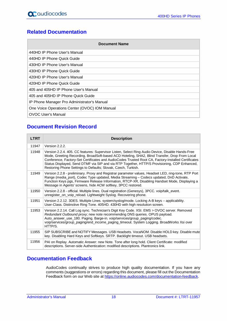
Related Documentation
Document Name
440HD IP Phone User's Manual 440HD IP Phone Quick Guide 430HD IP Phone User's Manual 430HD IP Phone Quick Guide 420HD IP Phone User's Manual 420HD IP Phone Quick Guide 405 and 405HD IP Phone User's Manual 405 and 405HD IP Phone Quick Guide IP Phone Manager Pro Administrator's Manual One Voice Operations Center (OVOC) IOM Manual OVOC User's Manual
Document Revision Record
LTRT Description
11947 Version 2.2.2. 11948 Version 2.2.4. 405. CC features: Supervisor Listen, Select Ring Audio Device, Disable Hands-Free
Mode, Greeting Recording, BroadSoft-based ACD Hoteling, SHA2, Blind Transfer, Drop From Local Conference, Factory-Set Certificates and AudioCodes Trusted Root CA, Factory-Installed Certificates Status Displayed, Send DTMF via SIP and via RTP Together, HTTP/S Provisioning, CDP Enhanced, Restoring Phone Settings to Defaults; Slovak, Czech, Turkish.
11949 Version 2.2.8 - preliminary. Proxy and Registrar parameter values, Headset LED, ring-tone, RTP Port Range (media_port), Codec Type updated, Media Streaming – Codecs updated, DnD Activate, Function Keys pgs, Firmware Release Information, RTCP-XR, Disabling Handset Mode, Displaying a Message in Agents' screens, hide ACW softkey, 3PCC restored.
11950 Version 2.2.8 - official. Multiple lines. Dual registration (Genesys), 3PCC. voip/talk_event. unregister_on_voip_reload. Lightweight Syslog. Recovering phone.
11951 Version 2.2.12. 3DES. Multiple Lines. system/syslog/mode. Locking A-B keys – applicability. User-Class. Distinctive Ring Tone. 405HD. 430HD with high resolution screen.
11953 Version 2.2.14. Call Log sync. Technician's Digit Key Code. XSI. EMS > OVOC server. Removed Redundant Outbound proxy; new note recommending DNS queries. OPUS payload. Auto_answer_use_180. Paging. Barge-in. voip/services/group_paging/codec. voip/services/group_paging/end_income_paging_timeout. System Logging. BroadWorks Xsi over HTTP/S.
11955 SIP SUBSCRIBE and NOTIFY Messages. USB Headsets. VocaNOM. Disable HOLD key. Disable mute key. Disabling Hard Keys and Softkeys. SRTP. Backlight timeout. USB headsets.
11956 PAI on Replay. Automatic Answer: new Note. Tone after long hold. Client Certificate: modified descriptions. Server-side Authentication: modified descriptions. Plantronics link.
Documentation Feedback AudioCodes continually strives to produce high quality documentation. If you have any comments (suggestions or errors) regarding this document, please fill out the Documentation Feedback form on our Web site at https://online.audiocodes.com/documentation-feedback.
Administrator's Manual 1. Introduction
Version 2.2.16 19 400HD Series IP Phones
1 Introduction This manual is intended for the system administrator responsible for setting up and configuring the 420HD, 430HD, 440HD, 405 and 405HD IP phones. AudioCodes' IP phones are based on AudioCodes' proprietary High Definition (HD) voice technology, providing clarity and a rich audio experience in Voice-over-IP (VoIP) calls. The phones are fully-featured telephones that provide voice communication over an IP network, allowing you to place and receive phone calls, put calls on hold, transfer calls, make conference calls, and so on. The phone offers a wide variety of management and configuration tools: Phone screen - easy-to-use, menu-driven screen providing basic phone configuration
and status capabilities Web interface - provides a user-friendly Web interface that runs on a Web browser
(Microsoft® Internet Explorer is the recommended browser). Configuration file - text-based file (created using any plain text editor such as
Microsoft's Notepad) containing configuration parameters and which is loaded to the phone using the Web interface or a TFTP, FTP, HTTP or HTTPS server.
IP Phone Manager Pro (see the IP Phone Manager Pro Administrator's Manual). For a detailed description on hardware installation and for operating the phone's call features, see the User's Manual.
Note:
• Boldened parameters enclosed in square brackets [ ] in the tables in this document indicate configuration file parameters.
• Web interface parameters are displayed in regular font above their web counterparts.

400HD Series IP Phones
Administrator's Manual 20 Document #: LTRT-11957
This page is intentionally left blank.

Part I Configuration Tools


Administrator's Manual 2. IP Phone User Interface
Version 2.2.16 23 400HD Series IP Phones
2 IP Phone User Interface The phone provides a Liquid Crystal Display (LCD) based screen, offering an intuitive, menu-driven interface for configuring the phone. The administrative tasks are performed in the phone's Administration menu.
Note: Screenshots of the 440HD are shown in this document. Screenshots of the 420HD and 405/405HD are only shown if they significantly differ.
2.1 Accessing the Administration Menu Here's how to access the Administration menu on the phone.
Note:
• The phone is password protected. The default password is 1234. To change the login password, use the phone's Web interface or Configuration file.
• After entering the password, the access session is applied to all the submenus. • To change the Administration screen's login password, use the phone's Web
interface or use the configuration file.
To access the Administration screen: 1. Press the MENU key on the phone and navigate down to Administration.
Note: Alternatively, after pressing the MENU key you can press an item's number to navigate to the item, for example, press 6 to navigate to Administration.
2. Press Select; you're prompted for a password.
3. Enter the administration password (Default: 1234) and then press the OK softkey.
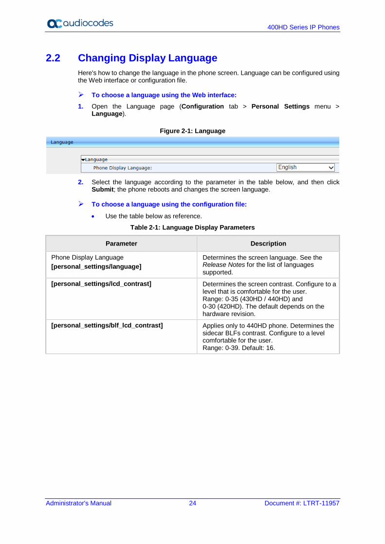
400HD Series IP Phones
Administrator's Manual 24 Document #: LTRT-11957
2.2 Changing Display Language Here's how to change the language in the phone screen. Language can be configured using the Web interface or configuration file.
To choose a language using the Web interface: 1. Open the Language page (Configuration tab > Personal Settings menu >
Language).
Figure 2-1: Language
2. Select the language according to the parameter in the table below, and then click
Submit; the phone reboots and changes the screen language.
To choose a language using the configuration file:
• Use the table below as reference.
Table 2-1: Language Display Parameters
Parameter Description
Phone Display Language [personal_settings/language]
Determines the screen language. See the Release Notes for the list of languages supported.
[personal_settings/lcd_contrast] Determines the screen contrast. Configure to a level that is comfortable for the user. Range: 0-35 (430HD / 440HD) and 0-30 (420HD). The default depends on the hardware revision.
[personal_settings/blf_lcd_contrast] Applies only to 440HD phone. Determines the sidecar BLFs contrast. Configure to a level comfortable for the user. Range: 0-39. Default: 16.
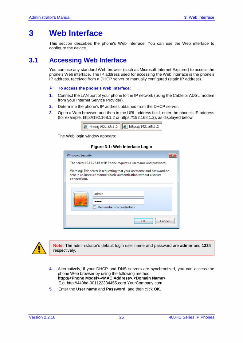
Administrator's Manual 3. Web Interface
Version 2.2.16 25 400HD Series IP Phones
3 Web Interface This section describes the phone's Web interface. You can use the Web interface to configure the device.
3.1 Accessing Web Interface You can use any standard Web browser (such as Microsoft Internet Explorer) to access the phone's Web interface. The IP address used for accessing the Web interface is the phone's IP address, received from a DHCP server or manually configured (static IP address).
To access the phone's Web interface: 1. Connect the LAN port of your phone to the IP network (using the Cable or ADSL modem
from your Internet Service Provider). 2. Determine the phone's IP address obtained from the DHCP server. 3. Open a Web browser, and then in the URL address field, enter the phone's IP address
(for example, http://192.168.1.2 or https://192.168.1.2), as displayed below:
The Web login window appears:
Figure 3-1: Web Interface Login
Note: The administrator's default login user name and password are admin and 1234 respectively.
4. Alternatively, if your DHCP and DNS servers are synchronized, you can access the phone Web browser by using the following method: http://<Phone Model>-<MAC Address>.<Domain Name> E.g. http://440hd-001122334455.corp.YourCompany.com
5. Enter the User name and Password, and then click OK.

400HD Series IP Phones
Administrator's Manual 26 Document #: LTRT-11957
3.2 Getting Started with the Web The areas of the Web interface are shown below:
Figure 3-2: Web Interface Areas
The Web interface is composed of the following main areas: Toolbar: displays AudioCodes logo and provides the following buttons:
• Home: opens the Home page
• Log off: closes the Web interface Navigation bar: provides tabs for accessing the configuration menus:
• Configuration: provides menus for configuring the phone. • Management: provides menus for various management tasks such as firmware
upgrade and changing the login username and password. • Status& Diagnostics: provides menus for displaying information on the status of
the phone, such as call history. Navigation tree: tree-like, hierarchical structure of menus pertaining to the selected tab
on the Navigation bar. Configuration pane: displays the configuration parameters pertaining to a selected
menu in the Navigation tree.
Navigation Bar
Toolbar
Navigation Tree
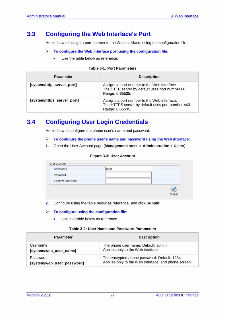
Administrator's Manual 3. Web Interface
Version 2.2.16 27 400HD Series IP Phones
3.3 Configuring the Web Interface's Port Here's how to assign a port number to the Web interface, using the configuration file.
To configure the Web interface port using the configuration file:
• Use the table below as reference.
Table 3-1: Port Parameters
Parameter Description
[system/http_server_port] Assigns a port number to the Web interface. The HTTP server by default uses port number 80. Range: 0-65535.
[system/https_server_port] Assigns a port number to the Web interface. The HTTPS server by default uses port number 443. Range: 0-65535.
3.4 Configuring User Login Credentials Here's how to configure the phone user's name and password.
To configure the phone user's name and password using the Web interface: 1. Open the User Account page (Management menu > Administration > Users):
Figure 3-3: User Account
2. Configure using the table below as reference, and click Submit.
To configure using the configuration file:
• Use the table below as reference.
Table 3-2: User Name and Password Parameters
Parameter Description
Username [system/web_user_name]
The phone user name. Default: admin. Applies only to the Web interface.
Password [system/web_user_password]
The encrypted phone password. Default: 1234. Applies only to the Web interface, and phone screen.

400HD Series IP Phones
Administrator's Manual 28 Document #: LTRT-11957
This page is intentionally left blank.

Administrator's Manual 4. Configuration File
Version 2.2.16 29 400HD Series IP Phones
4 Configuration File This section describes the configuration file and the parameters you can configure in it.
4.1 Introduction The configuration file can be loaded to the phone using the automatic provisioning mechanism, or manually from your local computer using the Web interface. The subsections below describe configuration file syntax and linking additional configuration files to a configuration file.
4.2 File Syntax The configuration file can be created using a standard ASCII, text-based program such as Notepad. The configuration file is a .cfg file with the file name being the phone's MAC address: <phone's MAC address>.cfg. The syntax of the configuration file is as follows: <parameter name>=<value>
Make sure the configuration file conforms to these guidelines: No spaces on either side of the equals (=) sign. Each parameter must be on a new line. Below is an example of part of a configuration file: system/type=440HD voip/line/0/enabled=1 voip/line/0/id=1234 voip/line/0/description=440HD voip/line/0/auth_name=1234 voip/line/0/auth_password=4321
4.3 Linking Multiple Files The Configuration file allows you to include links (URL and/or file name) to other Configuration files that provide additional parameter settings. This is especially useful in deployments with multiple phones, where the phones share common configuration but where each phone has some unique settings. In such a scenario, a phone's Configuration file can include unique parameter settings as well as links to additional Configuration files with settings common to all phones. Linking additional files is achieved by using the include function in the phone's Configuration file. For example, the below Configuration file provides links to additional Configuration files (shown in bolded font): system/type=440HD include 440HD_<MAC>_voip.cfg include vlan_conf.cfg include network_conf.cfg include provisioning_conf.cfg

400HD Series IP Phones
Administrator's Manual 30 Document #: LTRT-11957
In addition, the Configuration file can provide URL paths (FTP, TFTP, HTTP, or HTTPS) to where the additional files are located, as shown in the example below (shown in bolded font): system/type=440HD include http://10.10.10.10/440HD_<MAC>_voip.cfg include https://remote-pc/vlan_conf.cfg include tftp://10.10.10.10/440HD_<MAC>_network.cfg include ftp://remote-pc/provisining_conf.cfg
Note: If no URL is provided in the Configuration file, the files are retrieved according to the provisioning information (e.g. DHCP Option 160 as well as Option 66/67).
4.4 Downloading the Configuration File from the Phone For more information, see Maintenance.
4.5 Creating Configuration Files using VoIProvision Utility When installing AudioCodes' phones, the network administrator typically configures each installed phone automatically. Using DHCP options or other methods, the phone can be instructed to download a configuration file. This file is typically unique to each phone, based on the MAC address. This MAC-specific configuration file is generated with phone specific configuration parameters; such as, the extension ID, name and authentication password. Not all of the iPBX and SoftSwitch vendors (and especially the full solution vendors) include provisioning in their interoperability programs. As an IP phone vendor, AudioCodes is required to provide a standalone provisioning tool that will enable the provisioning of its phones in such environments. AudioCodes provides a tool that assists in the automatic generation of configuration files. These files can be generated for the initial configuration of the phones and then later regenerated for subsequent configuration updates as required.
4.5.1 Configuration File Format The detailed format of the phones' configuration files are described in the appendix. The following is an output example of an automatically generated MAC-specific file: system/type=440HD voip/line/0/enabled=1 voip/line/0/id=56832432 voip/line/0/auth_name=3423fdwer2tre voip/line/0/auth_password=123456 include global.cfg
4.5.2 Global Configuration File In addition to the MAC-specific files, it is recommended to maintain a single global configuration file, which contains parameters that are common to all phones in the specific site. The MAC-specific files can call the global file (using the 'include' method) as illustrated in the above example. For more information, see 'Linking Additional Files using “Include”' in the Administrator's Manual.
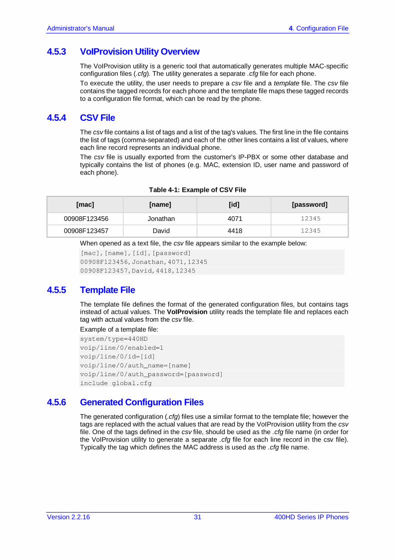
Administrator's Manual 4. Configuration File
Version 2.2.16 31 400HD Series IP Phones
4.5.3 VoIProvision Utility Overview The VoIProvision utility is a generic tool that automatically generates multiple MAC-specific configuration files (.cfg). The utility generates a separate .cfg file for each phone. To execute the utility, the user needs to prepare a csv file and a template file. The csv file contains the tagged records for each phone and the template file maps these tagged records to a configuration file format, which can be read by the phone.
4.5.4 CSV File The csv file contains a list of tags and a list of the tag's values. The first line in the file contains the list of tags (comma-separated) and each of the other lines contains a list of values, where each line record represents an individual phone. The csv file is usually exported from the customer's IP-PBX or some other database and typically contains the list of phones (e.g. MAC, extension ID, user name and password of each phone).
Table 4-1: Example of CSV File
[mac] [name] [id] [password]
00908F123456 Jonathan 4071 12345
00908F123457 David 4418 12345
When opened as a text file, the csv file appears similar to the example below: [mac],[name],[id],[password] 00908F123456,Jonathan,4071,12345 00908F123457,David,4418,12345
4.5.5 Template File The template file defines the format of the generated configuration files, but contains tags instead of actual values. The VoIProvision utility reads the template file and replaces each tag with actual values from the csv file. Example of a template file: system/type=440HD voip/line/0/enabled=1 voip/line/0/id=[id] voip/line/0/auth_name=[name] voip/line/0/auth_password=[password] include global.cfg
4.5.6 Generated Configuration Files
The generated configuration (.cfg) files use a similar format to the template file; however the tags are replaced with the actual values that are read by the VoIProvision utility from the csv file. One of the tags defined in the csv file, should be used as the .cfg file name (in order for the VoIProvision utility to generate a separate .cfg file for each line record in the csv file). Typically the tag which defines the MAC address is used as the .cfg file name.
400HD Series IP Phones
Administrator's Manual 32 Document #: LTRT-11957
4.5.7 Starting the VoIProvision Utility The VoIProvision utility can run on both the Linux and Windows platforms. The VoIProvision utility initially parses the csv file to generate the list of tags. The VoIProvision then reads each line record of values in the csv file and for each line record, does the following: Parses the line record to create a list of values Opens the template file Generates the .cfg file name and create a new .cfg file Reads the template file, associates the mapped tags with actual values from the csv file
and writes the result to the .cfg file Closes the .cfg file and template file
4.5.8 Usage USAGE: VoIProvision<csv file><template file><.cfg file>
Note the following: The first line of the csv file contains the list of tags (e.g.,
[mac],[name],[id]). The remainder of the csv file contains a line record per .cfg file (e.g.
00908f112233,4071,Ethan). There is no restriction on the format of the tags (e.g., [tag] or @tag@). The template file defines the .cfg file format. During VoIProvision
run-time, the mapped tags in the template file are associated to actual values that are read from the csv file.
Currently only a single tag can be defined per line record in the template file.
The .cfg file name should represent the string of one of the predefined tags in order to generate a separate .cfg file per csv line record (e.g., [mac].cfg).
4.6 Using the Encryption Tool AudioCodes' phones use the Triple Data Encryption Standard (3DES) algorithm for encryption. Here's how to use the encryption tool.
4.6.1 Encrypting Configuration Files Here's how to encrypt the configuration file. For example, you may wish to encrypt the configuration file when it is send over an unsecure network.
To encrypt the configuration file: At the command line prompt, specify the following:
encryption_tool.exe –f <filename>.cfg
where <file name>.cfg specifies the name of the Configuration file that you wish to encrypt. Once the Configuration file is encrypted, it receives the suffix '.cfx' (e.g. Conf.cfx). This is the file that you should specify in the 'Configuration URL' and the 'Dynamic Configuration URL' fields when performing automatic provisioning (see Part II 'Automatic Provisioning').
Administrator's Manual 4. Configuration File
Version 2.2.16 33 400HD Series IP Phones
4.6.2 Encrypting Passwords in the Configuration File Here's how to encrypt phone passwords used in the configuration process, for example, the 'System' password and the 'SIP Authentication' password.
To encrypt passwords: 1. At the command line prompt, specify the following:
encryption_tool.exe –s <password_string>
where <password_string> specifies the string of the password that you wish to encrypt. Once the password is encrypted, a string is generated with the following syntax: {"<encrypted_string>"}
For example: {"0qrNRpSJ6aE="}
2. Copy the generated string (including the {“ “}) with the syntax specified above to the relevant parameter in the Configuration file. For example, if you encrypted the SIP authentication password, the following is displayed in the relevant line in the configuration file: voip/line/0/auth_password={"0qrNRpSJ6aE="}
Note: It's recommended to encrypt the 'System' password using this procedure. If you choose not to, the 'System' password is by default encrypted using MD5.

400HD Series IP Phones
Administrator's Manual 34 Document #: LTRT-11957
This page is intentionally left blank.
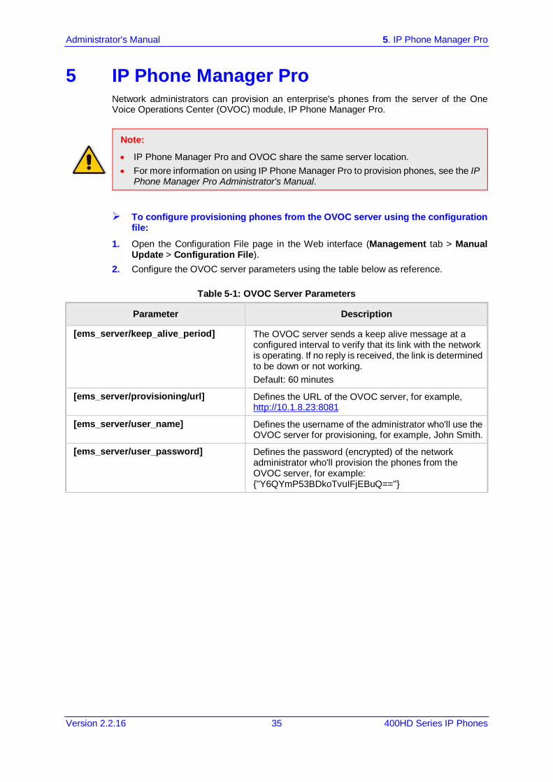
Administrator's Manual 5. IP Phone Manager Pro
Version 2.2.16 35 400HD Series IP Phones
5 IP Phone Manager Pro Network administrators can provision an enterprise's phones from the server of the One Voice Operations Center (OVOC) module, IP Phone Manager Pro.
Note:
• IP Phone Manager Pro and OVOC share the same server location. • For more information on using IP Phone Manager Pro to provision phones, see the IP
Phone Manager Pro Administrator's Manual.
To configure provisioning phones from the OVOC server using the configuration file:
1. Open the Configuration File page in the Web interface (Management tab > Manual Update > Configuration File).
2. Configure the OVOC server parameters using the table below as reference.
Table 5-1: OVOC Server Parameters
Parameter Description
[ems_server/keep_alive_period] The OVOC server sends a keep alive message at a configured interval to verify that its link with the network is operating. If no reply is received, the link is determined to be down or not working. Default: 60 minutes
[ems_server/provisioning/url] Defines the URL of the OVOC server, for example, http://10.1.8.23:8081
[ems_server/user_name] Defines the username of the administrator who'll use the OVOC server for provisioning, for example, John Smith.
[ems_server/user_password] Defines the password (encrypted) of the network administrator who'll provision the phones from the OVOC server, for example: {"Y6QYmP53BDkoTvuIFjEBuQ=="}

400HD Series IP Phones
Administrator's Manual 36 Document #: LTRT-11957
This page is intentionally left blank.

Part II Automatic Provisioning

Administrator's Manual 6. Introduction
Version 2.2.16 39 400HD Series IP Phones
6 Introduction By default, the phone is ready for out-of-the-box deployment using its automatic provisioning capabilities. The phone offers a built-in mechanism for automatically upgrading its software image and updating its configuration. This method is used to upgrade the phone firmware and update its configuration, by remotely downloading an updated software image and configuration file. The automatic update mechanism helps you keep your software image and configuration up-to-date, by performing routine checks for newer software versions and configuration files, as well as allowing you to perform manual checks. The automatic update mechanism is as follows: Before connecting the phone, verify that the provisioning server is running and that the
firmware and configuration files are located in the correct location. Connect your phone to the IP network, and then connect the phone to the power outlet. During DHCP negotiation, the phone requests for DHCP options 66/67/160 to receive
provisioning information. The DHCP server should respond with Option 160 providing the provisioning URL or Options 66 and 67 providing the TFTP IP address and firmware file name respectively.
The phone then checks whether new firmware is available by checking the firmware file header. If the version is different from the one currently running on the phone, the phone downloads the complete image and burns it to its flash memory.
If a new firmware is unavailable, the phone then checks whether a new configuration is available. If a configuration file is available on the server, the phone downloads it and updates the phone's configuration after verifying that the configuration file is related to the phone model. When a configuration update is needed, the phone might reboot.
Note: • In the DHCP Discover message, the phone publishes its model name in Option fields
60 and 77 (e.g. 440HD). If the administrator wants to provide different provisioning information to different phone models, the administrator can set up a policy in the DHCP server according to the phone model name.
• If the phone is powered off for some reason during the firmware upgrade process, the phone will be unusable and the recovery process must be performed.
• You can only use firmware files with an .img extension and configuration files with a .cfg extension.
• To "force" the firmware or configuration file to be retrieved immediately regardless of the 'Check Period' value, click the Check Now button on the relevant page on the Web interface.
• An additional auto-provisioning mechanism is supported if the provisioning environment does not provide all the required information (e.g. DHCP options).
Note: Automatic mass provisioning of phones using DHCP can alternatively be performed from the OVOC’s IP Phones Manager Pro module. For more information, see the IP Phone Manager Pro Administrator's Manual.

400HD Series IP Phones
Administrator's Manual 40 Document #: LTRT-11957
This page is intentionally left blank.
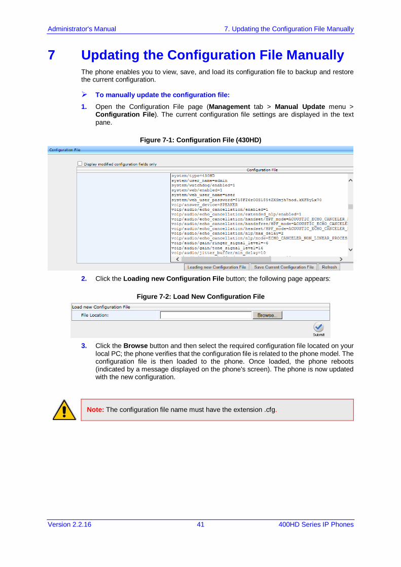
Administrator's Manual 7. Updating the Configuration File Manually
Version 2.2.16 41 400HD Series IP Phones
7 Updating the Configuration File Manually The phone enables you to view, save, and load its configuration file to backup and restore the current configuration.
To manually update the configuration file: 1. Open the Configuration File page (Management tab > Manual Update menu >
Configuration File). The current configuration file settings are displayed in the text pane.
Figure 7-1: Configuration File (430HD)
2. Click the Loading new Configuration File button; the following page appears:
Figure 7-2: Load New Configuration File
3. Click the Browse button and then select the required configuration file located on your
local PC; the phone verifies that the configuration file is related to the phone model. The configuration file is then loaded to the phone. Once loaded, the phone reboots (indicated by a message displayed on the phone's screen). The phone is now updated with the new configuration.
Note: The configuration file name must have the extension .cfg.

400HD Series IP Phones
Administrator's Manual 42 Document #: LTRT-11957
To save the configuration file: In the Configuration File page, click the Saving Current Configuration File button, and
then save the current phone configuration file to a folder on your local PC.
Note: When creating a new configuration file, make sure the system/type parameter in the configuration file is set to the correct phone model (e.g., 430HD).
Administrator's Manual 8. Setting up Network for Auto Provisioning
Version 2.2.16 43 400HD Series IP Phones
8 Setting up Network for Auto Provisioning The phone supports dynamic VLAN discovery, dynamic IP addressing (DHCP), and NTP (as client).
Note: For manual configuration of Network Settings, see Section 13.

400HD Series IP Phones
Administrator's Manual 44 Document #: LTRT-11957
This page is intentionally left blank.
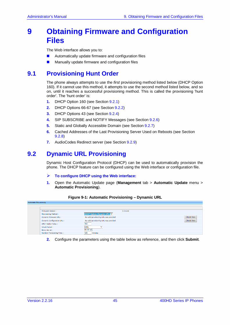
Administrator's Manual 9. Obtaining Firmware and Configuration Files
Version 2.2.16 45 400HD Series IP Phones
9 Obtaining Firmware and Configuration Files The Web interface allows you to: Automatically update firmware and configuration files Manually update firmware and configuration files
9.1 Provisioning Hunt Order The phone always attempts to use the first provisioning method listed below (DHCP Option 160). If it cannot use this method, it attempts to use the second method listed below, and so on, until it reaches a successful provisioning method. This is called the provisioning 'hunt order'. The 'hunt order' is: 1. DHCP Option 160 (see Section 9.2.1) 2. DHCP Options 66-67 (see Section 9.2.2) 3. DHCP Options 43 (see Section 9.2.4) 4. SIP SUBSCRIBE and NOTIFY Messages (see Section 9.2.6) 5. Static and Globally Accessible Domain (see Section 9.2.7) 6. Cached Addresses of the Last Provisioning Server Used on Reboots (see Section
9.2.8) 7. AudioCodes Redirect server (see Section 9.2.9)
9.2 Dynamic URL Provisioning Dynamic Host Configuration Protocol (DHCP) can be used to automatically provision the phone. The DHCP feature can be configured using the Web interface or configuration file.
To configure DHCP using the Web interface: 1. Open the Automatic Update page (Management tab > Automatic Update menu >
Automatic Provisioning).
Figure 9-1: Automatic Provisioning – Dynamic URL
2. Configure the parameters using the table below as reference, and then click Submit.
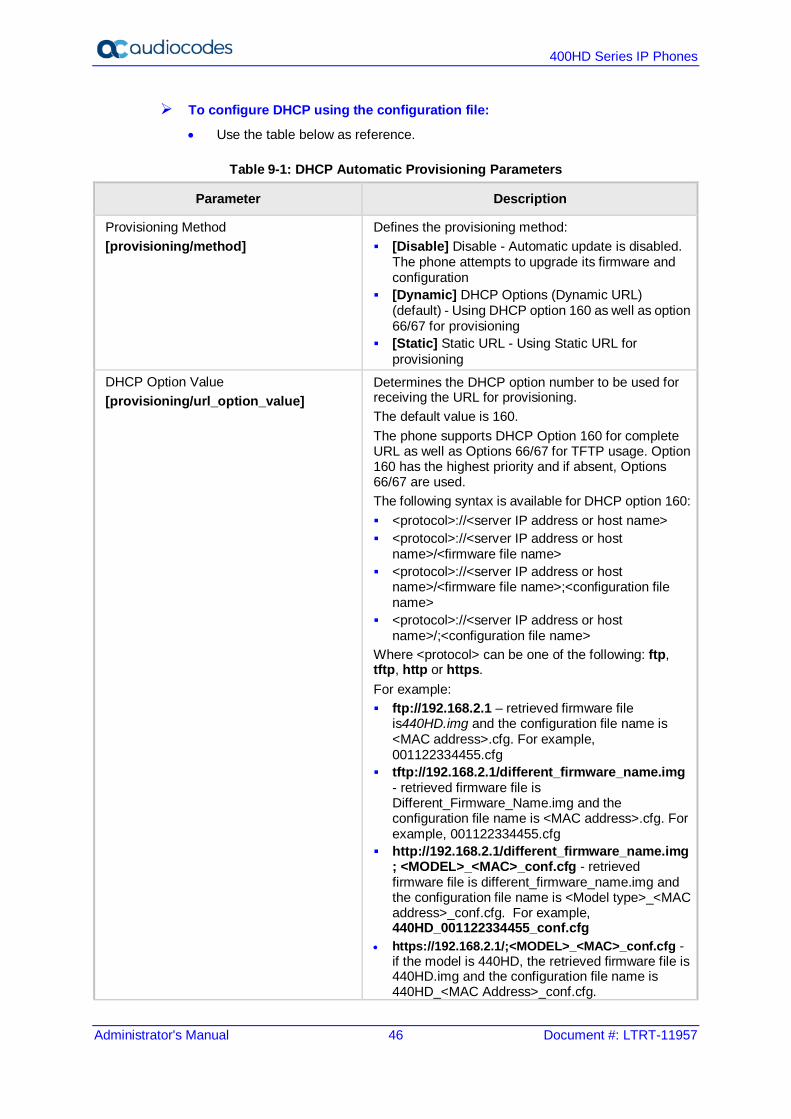
400HD Series IP Phones
Administrator's Manual 46 Document #: LTRT-11957
To configure DHCP using the configuration file:
• Use the table below as reference.
Table 9-1: DHCP Automatic Provisioning Parameters
Parameter Description
Provisioning Method [provisioning/method]
Defines the provisioning method: [Disable] Disable - Automatic update is disabled.
The phone attempts to upgrade its firmware and configuration
[Dynamic] DHCP Options (Dynamic URL) (default) - Using DHCP option 160 as well as option 66/67 for provisioning
[Static] Static URL - Using Static URL for provisioning
DHCP Option Value [provisioning/url_option_value]
Determines the DHCP option number to be used for receiving the URL for provisioning. The default value is 160. The phone supports DHCP Option 160 for complete URL as well as Options 66/67 for TFTP usage. Option 160 has the highest priority and if absent, Options 66/67 are used. The following syntax is available for DHCP option 160: <protocol>://<server IP address or host name> <protocol>://<server IP address or host
name>/<firmware file name> <protocol>://<server IP address or host
name>/<firmware file name>;<configuration file name>
<protocol>://<server IP address or host name>/;<configuration file name>
Where <protocol> can be one of the following: ftp, tftp, http or https. For example: ftp://192.168.2.1 – retrieved firmware file
is440HD.img and the configuration file name is <MAC address>.cfg. For example, 001122334455.cfg
tftp://192.168.2.1/different_firmware_name.img - retrieved firmware file is Different_Firmware_Name.img and the configuration file name is <MAC address>.cfg. For example, 001122334455.cfg
http://192.168.2.1/different_firmware_name.img; <MODEL>_<MAC>_conf.cfg - retrieved firmware file is different_firmware_name.img and the configuration file name is <Model type>_<MAC address>_conf.cfg. For example, 440HD_001122334455_conf.cfg
• https://192.168.2.1/;<MODEL>_<MAC>_conf.cfg - if the model is 440HD, the retrieved firmware file is 440HD.img and the configuration file name is 440HD_<MAC Address>_conf.cfg.

Administrator's Manual 9. Obtaining Firmware and Configuration Files
Version 2.2.16 47 400HD Series IP Phones
Parameter Description
For example, 440HD_001122334455_conf.cfg The following syntax is available for DHCP Options 66/67: Option 66 must be a valid IP address or host name
of a TFTP server only. Option 67 must be the firmware name. If Option 67 is absent, the phone requests for the 440HD.img image file. For example: Option 66: 192.168.2.1 or myTFTPServer Option 67: 440HD_2.2.2.img Note: This parameter is applicable only when method is
configured to Dynamic. It is recommended to leave the parameter at its
default value to avoid conflict with other DHCP options settings.
Random Provisioning Time [provisioning/random_provisioning_time]
Defines the maximum random number to start the provisioning process. This is used for periodic checking of firmware and configuration files to avoid multiple devices from starting the upgrade process at the same time. When the device is meant to start the upgrade, the device randomly selects a number between 1 and the value set for random_provisioning_time and performs the check only after the random time. The valid range is 0-65535. The default value is 120.
Check Period [provisioning/period/type]
Defines the period type for automatic provisioning: [hourly] Hourly - Sets an interval in hours. [daily] Daily (default) - Sets an hour in the day. [weekly] Weekly - Sets a day in the week and an
hour in the day. [powerup] On Power-up Only - The phone tries to
upgrade only after power-up. Every (Check Period = Hourly) [provisioning/period/hourly/hours_interval]
The interval in hours for automatically checking for new firmware and configuration files. The valid range is 1 to 168. The default is 24. Note: This parameter is applicable only when type is configured to hourly.
Every day at [provisioning/period/daily/time]
The hour in the day for automatically checking for new firmware and configuration files. The format of this value is hh:mm, where hh is hour and mm is minutes. For example, 00:30. The default time is 00:00. Note: This parameter is applicable only when type is configured to daily.
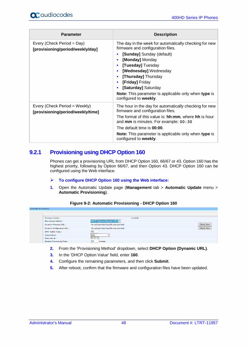
400HD Series IP Phones
Administrator's Manual 48 Document #: LTRT-11957
Parameter Description
Every (Check Period = Day) [provisioning/period/weekly/day]
The day in the week for automatically checking for new firmware and configuration files. [Sunday] Sunday (default) [Monday] Monday [Tuesday] Tuesday [Wednesday] Wednesday [Thursday] Thursday [Friday] Friday [Saturday] Saturday Note: This parameter is applicable only when type is configured to weekly.
Every (Check Period = Weekly) [provisioning/period/weekly/time]
The hour in the day for automatically checking for new firmware and configuration files. The format of this value is: hh:mm, where hh is hour and mm is minutes. For example: 00:30 The default time is 00:00. Note: This parameter is applicable only when type is configured to weekly.
9.2.1 Provisioning using DHCP Option 160 Phones can get a provisioning URL from DHCP Option 160, 66/67 or 43. Option 160 has the highest priority, following by Option 66/67, and then Option 43. DHCP Option 160 can be configured using the Web interface.
To configure DHCP Option 160 using the Web interface: 1. Open the Automatic Update page (Management tab > Automatic Update menu >
Automatic Provisioning).
Figure 9-2: Automatic Provisioning - DHCP Option 160
2. From the 'Provisioning Method' dropdown, select DHCP Option (Dynamic URL). 3. In the 'DHCP Option Value' field, enter 160. 4. Configure the remaining parameters, and then click Submit. 5. After reboot, confirm that the firmware and configuration files have been updated.
Administrator's Manual 9. Obtaining Firmware and Configuration Files
Version 2.2.16 49 400HD Series IP Phones
9.2.2 Technician's Digit Key Code Technicians installing phones at customer sites do not need to connect laptops to phones to provision them. After connecting phones to the network, technicians can enter a specific digit key code which changes the phones' provisioning URL to the server's URL. If the code that the technician enters matches, the phones are automatically provisioned from that server.
Note: The feature requires software customization.
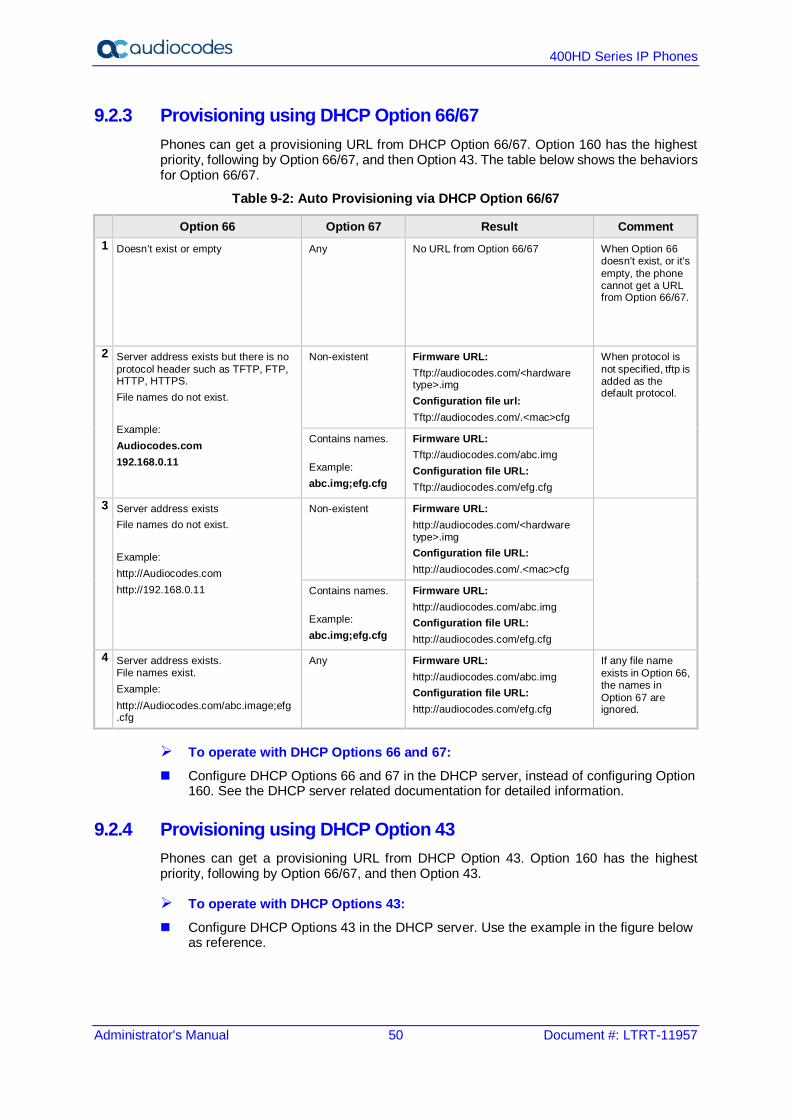
400HD Series IP Phones
Administrator's Manual 50 Document #: LTRT-11957
9.2.3 Provisioning using DHCP Option 66/67 Phones can get a provisioning URL from DHCP Option 66/67. Option 160 has the highest priority, following by Option 66/67, and then Option 43. The table below shows the behaviors for Option 66/67.
Table 9-2: Auto Provisioning via DHCP Option 66/67
Option 66 Option 67 Result Comment 1 Doesn’t exist or empty Any No URL from Option 66/67 When Option 66
doesn’t exist, or it’s empty, the phone cannot get a URL from Option 66/67.
2 Server address exists but there is no protocol header such as TFTP, FTP, HTTP, HTTPS. File names do not exist. Example: Audiocodes.com 192.168.0.11
Non-existent Firmware URL: Tftp://audiocodes.com/<hardware type>.img Configuration file url: Tftp://audiocodes.com/.<mac>cfg
When protocol is not specified, tftp is added as the default protocol.
Contains names. Example: abc.img;efg.cfg
Firmware URL: Tftp://audiocodes.com/abc.img Configuration file URL: Tftp://audiocodes.com/efg.cfg
3 Server address exists File names do not exist. Example: http://Audiocodes.com
http://192.168.0.11
Non-existent Firmware URL: http://audiocodes.com/<hardware type>.img Configuration file URL: http://audiocodes.com/.<mac>cfg
Contains names. Example: abc.img;efg.cfg
Firmware URL: http://audiocodes.com/abc.img
Configuration file URL: http://audiocodes.com/efg.cfg
4 Server address exists. File names exist. Example: http://Audiocodes.com/abc.image;efg.cfg
Any Firmware URL: http://audiocodes.com/abc.img
Configuration file URL: http://audiocodes.com/efg.cfg
If any file name exists in Option 66, the names in Option 67 are ignored.
To operate with DHCP Options 66 and 67: Configure DHCP Options 66 and 67 in the DHCP server, instead of configuring Option
160. See the DHCP server related documentation for detailed information.
9.2.4 Provisioning using DHCP Option 43 Phones can get a provisioning URL from DHCP Option 43. Option 160 has the highest priority, following by Option 66/67, and then Option 43.
To operate with DHCP Options 43: Configure DHCP Options 43 in the DHCP server. Use the example in the figure below
as reference.
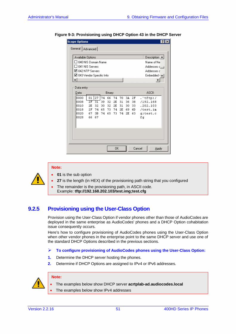
Administrator's Manual 9. Obtaining Firmware and Configuration Files
Version 2.2.16 51 400HD Series IP Phones
Figure 9-3: Provisioning using DHCP Option 43 in the DHCP Server
Note:
• 01 is the sub option • 27 is the length (in HEX) of the provisioning path string that you configured • The remainder is the provisioning path, in ASCII code.
Example: tftp://192.168.202.103/test.img;test.cfg
9.2.5 Provisioning using the User-Class Option Provision using the User-Class Option if vendor phones other than those of AudioCodes are deployed in the same enterprise as AudioCodes' phones and a DHCP Option cohabitation issue consequently occurs. Here's how to configure provisioning of AudioCodes phones using the User-Class Option when other vendor phones in the enterprise point to the same DHCP server and use one of the standard DHCP Options described in the previous sections.
To configure provisioning of AudioCodes phones using the User-Class Option: 1. Determine the DHCP server hosting the phones. 2. Determine if DHCP Options are assigned to IPv4 or IPv6 addresses.
Note:
• The examples below show DHCP server acrtplab-ad.audiocodes.local • The examples below show IPv4 addresses
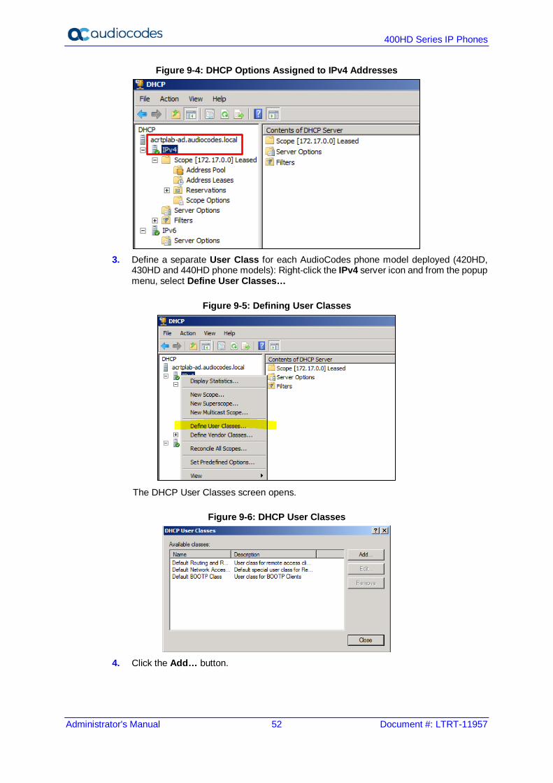
400HD Series IP Phones
Administrator's Manual 52 Document #: LTRT-11957
Figure 9-4: DHCP Options Assigned to IPv4 Addresses
3. Define a separate User Class for each AudioCodes phone model deployed (420HD,
430HD and 440HD phone models): Right-click the IPv4 server icon and from the popup menu, select Define User Classes…
Figure 9-5: Defining User Classes
The DHCP User Classes screen opens.
Figure 9-6: DHCP User Classes
4. Click the Add… button.
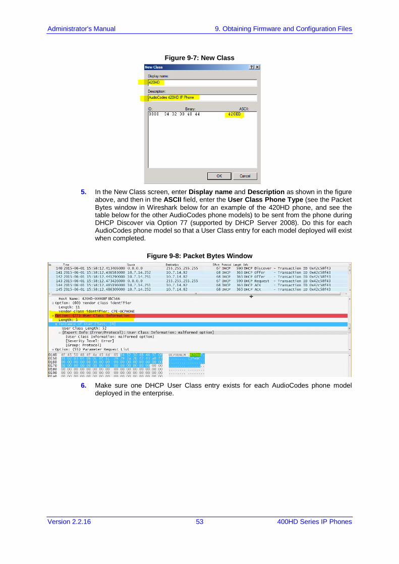
Administrator's Manual 9. Obtaining Firmware and Configuration Files
Version 2.2.16 53 400HD Series IP Phones
Figure 9-7: New Class
5. In the New Class screen, enter Display name and Description as shown in the figure
above, and then in the ASCII field, enter the User Class Phone Type (see the Packet Bytes window in Wireshark below for an example of the 420HD phone, and see the table below for the other AudioCodes phone models) to be sent from the phone during DHCP Discover via Option 77 (supported by DHCP Server 2008). Do this for each AudioCodes phone model so that a User Class entry for each model deployed will exist when completed.
Figure 9-8: Packet Bytes Window
6. Make sure one DHCP User Class entry exists for each AudioCodes phone model
deployed in the enterprise.
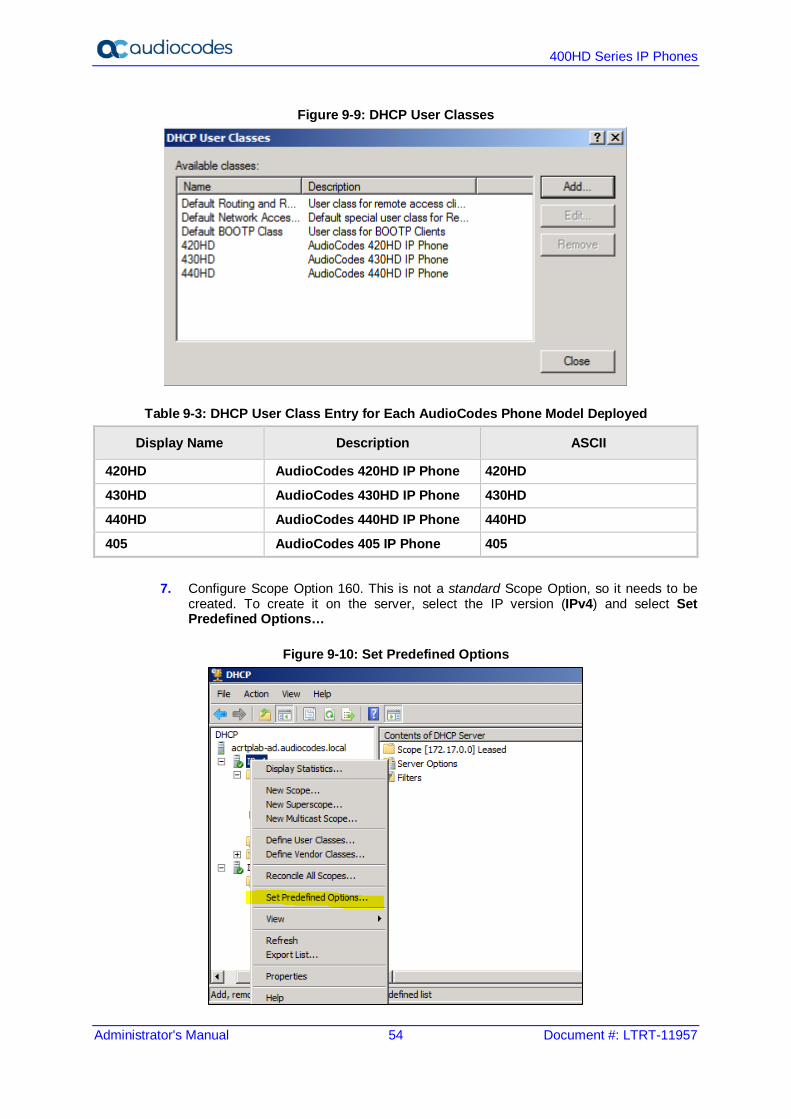
400HD Series IP Phones
Administrator's Manual 54 Document #: LTRT-11957
Figure 9-9: DHCP User Classes
Table 9-3: DHCP User Class Entry for Each AudioCodes Phone Model Deployed
Display Name Description ASCII
420HD AudioCodes 420HD IP Phone 420HD
430HD AudioCodes 430HD IP Phone 430HD
440HD AudioCodes 440HD IP Phone 440HD
405 AudioCodes 405 IP Phone 405
7. Configure Scope Option 160. This is not a standard Scope Option, so it needs to be created. To create it on the server, select the IP version (IPv4) and select Set Predefined Options…
Figure 9-10: Set Predefined Options

Administrator's Manual 9. Obtaining Firmware and Configuration Files
Version 2.2.16 55 400HD Series IP Phones
8. From the 'Option class' dropdown, select DHCP Standard Options, and then click the Add… button.
Figure 9-11: Predefined Options and Values
9. Add the AudioCodes 160 Option as shown below, and then click OK.
Figure 9-12: Option Type – Add AudioCodes 160 Option
10. Add the OVOC server location using HTTP. In the figure below, it's http://<OVOC
server IP address>/firmwarefiles;ipp/dhcpoption160.cfg. See the IP Phone Manager Pro Administrator’s Manual for more information.

400HD Series IP Phones
Administrator's Manual 56 Document #: LTRT-11957
Figure 9-13: Predefined Options and Values – Add OVOC Server Location
Note: Make sure you defined in the enterprise's DHCP server http://<OVOC server IP address>/firmwarefiles;ipp/dhcpoption160.cfg for DHCP Option 160.
11. Decide if the DHCP Scope Option needs to be assigned to phones in a specific VLAN
(Scope), or to the entire server (acrtplab-ad.audiocodes.local) for IPv4 addresses. VLAN Scope 12. Assign to a specific VLAN (Scope of IP addresses such as the Scope below 172.17.0.0,
or to multiple Scopes, to be performed separately on each Scope). a. If selecting a VLAN, expand the 'Scope Leased' folder, select 'Scope Options', and
then select Configure Options from the popup menu.
Figure 9-14: 'Scope Leased' Folder - Configure Options
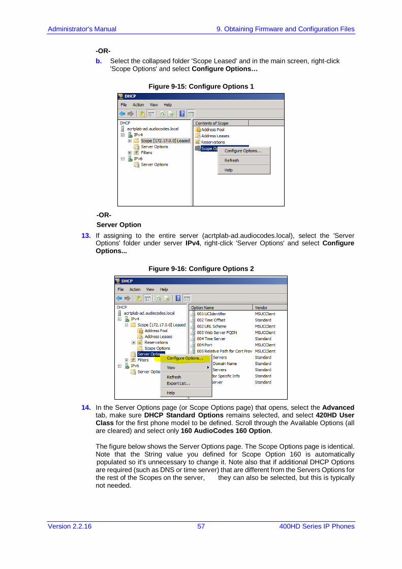
Administrator's Manual 9. Obtaining Firmware and Configuration Files
Version 2.2.16 57 400HD Series IP Phones
-OR- b. Select the collapsed folder 'Scope Leased' and in the main screen, right-click
'Scope Options' and select Configure Options…
Figure 9-15: Configure Options 1
-OR- Server Option 13. If assigning to the entire server (acrtplab-ad.audiocodes.local), select the 'Server
Options' folder under server IPv4, right-click 'Server Options' and select Configure Options...
Figure 9-16: Configure Options 2
14. In the Server Options page (or Scope Options page) that opens, select the Advanced
tab, make sure DHCP Standard Options remains selected, and select 420HD User Class for the first phone model to be defined. Scroll through the Available Options (all are cleared) and select only 160 AudioCodes 160 Option. The figure below shows the Server Options page. The Scope Options page is identical. Note that the String value you defined for Scope Option 160 is automatically populated so it's unnecessary to change it. Note also that if additional DHCP Options are required (such as DNS or time server) that are different from the Servers Options for the rest of the Scopes on the server, they can also be selected, but this is typically not needed.

400HD Series IP Phones
Administrator's Manual 58 Document #: LTRT-11957
Figure 9-17: Server Options
15. Click Apply and then follow the same procedure to add the 430HD and 440HD user
classes. After adding them, click the OK button.
You've successfully created three separate Scope Options that will only allow AudioCodes phones to connect to IP Phone Manager Pro when they boot up and will prevent other vendor phones from receiving the OVOC as their provisioning server.
Figure 9-18: Three Scope Options Created
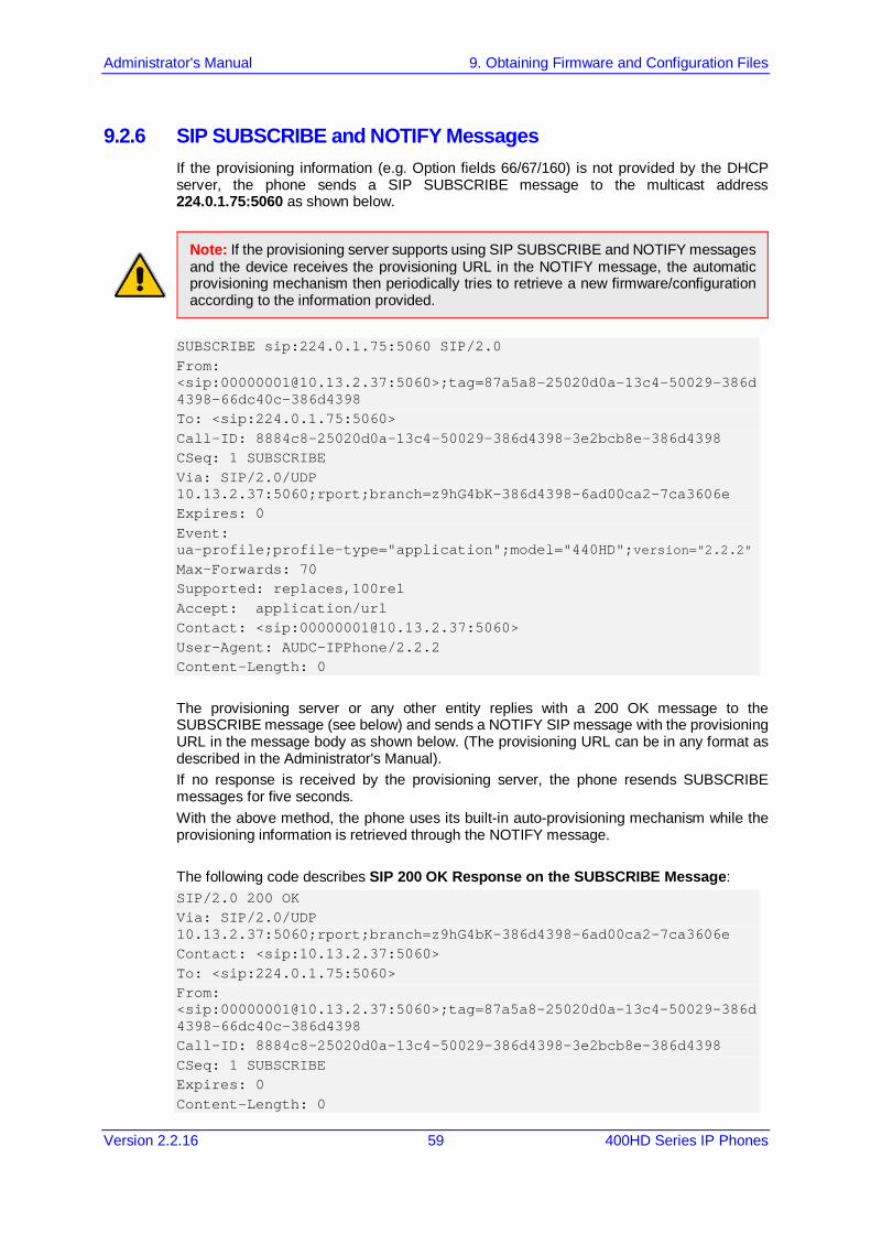
Administrator's Manual 9. Obtaining Firmware and Configuration Files
Version 2.2.16 59 400HD Series IP Phones
9.2.6 SIP SUBSCRIBE and NOTIFY Messages If the provisioning information (e.g. Option fields 66/67/160) is not provided by the DHCP server, the phone sends a SIP SUBSCRIBE message to the multicast address 224.0.1.75:5060 as shown below.
Note: If the provisioning server supports using SIP SUBSCRIBE and NOTIFY messages and the device receives the provisioning URL in the NOTIFY message, the automatic provisioning mechanism then periodically tries to retrieve a new firmware/configuration according to the information provided.
SUBSCRIBE sip:224.0.1.75:5060 SIP/2.0 From: <sip:[email protected]:5060>;tag=87a5a8-25020d0a-13c4-50029-386d4398-66dc40c-386d4398 To: <sip:224.0.1.75:5060> Call-ID: 8884c8-25020d0a-13c4-50029-386d4398-3e2bcb8e-386d4398 CSeq: 1 SUBSCRIBE Via: SIP/2.0/UDP 10.13.2.37:5060;rport;branch=z9hG4bK-386d4398-6ad00ca2-7ca3606e Expires: 0 Event: ua-profile;profile-type="application";model="440HD";version="2.2.2" Max-Forwards: 70 Supported: replaces,100rel Accept: application/url Contact: <sip:[email protected]:5060> User-Agent: AUDC-IPPhone/2.2.2 Content-Length: 0
The provisioning server or any other entity replies with a 200 OK message to the SUBSCRIBE message (see below) and sends a NOTIFY SIP message with the provisioning URL in the message body as shown below. (The provisioning URL can be in any format as described in the Administrator's Manual). If no response is received by the provisioning server, the phone resends SUBSCRIBE messages for five seconds. With the above method, the phone uses its built-in auto-provisioning mechanism while the provisioning information is retrieved through the NOTIFY message.
The following code describes SIP 200 OK Response on the SUBSCRIBE Message: SIP/2.0 200 OK Via: SIP/2.0/UDP 10.13.2.37:5060;rport;branch=z9hG4bK-386d4398-6ad00ca2-7ca3606e Contact: <sip:10.13.2.37:5060> To: <sip:224.0.1.75:5060> From: <sip:[email protected]:5060>;tag=87a5a8-25020d0a-13c4-50029-386d4398-66dc40c-386d4398 Call-ID: 8884c8-25020d0a-13c4-50029-386d4398-3e2bcb8e-386d4398 CSeq: 1 SUBSCRIBE Expires: 0 Content-Length: 0

400HD Series IP Phones
Administrator's Manual 60 Document #: LTRT-11957
The following code describes SIP NOTIFY Message with Provisioning Information. NOTIFY sip:10.13.2.37:5060 SIP/2.0 Via: SIP/2.0/UDP 10.13.2.37:5060;rport;branch=z9hG4bK-386d4398-6ad00ca2-7ca3606e Max-Forwards: 20 Contact: <sip:10.13.4.121:5060> To: <sip:224.0.1.75:5060> From: <sip:[email protected]:5060>;tag=87a5a8-25020d0a-13c4-50029-386d4398-66dc40c-386d4398 Call-ID: 8884c8-25020d0a-13c4-50029-386d4398-3e2bcb8e-386d4398 CSeq: 1 NOTIFY Content-Type: application/url Subscription-State: terminated;reason=timeout Event: ua-profile;profile-type="application";model="440HD";version="2.2.2" Content-Length: 18 tftp://10.13.4.121
The following code describes SIP SUBSCRIBE Message to Obtain Provisioning Information. SUBSCRIBE sip:224.0.1.75:5060 SIP/2.0 From: <sip:[email protected]:5060>;tag=87a5a8-25020d0a-13c4-50029-386d4398-66dc40c-386d4398 To: <sip:224.0.1.75:5060> Call-ID: 8884c8-25020d0a-13c4-50029-386d4398-3e2bcb8e-386d4398 CSeq: 1 SUBSCRIBE Via: SIP/2.0/UDP 10.13.2.37:5060;rport;branch=z9hG4bK-386d4398-6ad00ca2-7ca3606e Expires: 0 Event: ua-profile;profile-type="application";model="440HD";version="2.2.2" Max-Forwards: 70 Supported: replaces,100rel Accept: application/url Contact: <sip:[email protected]:5060> User-Agent: AUDC-IPPhone/2.2.2 Content-Length: 0
With the above method, the phone uses its built-in auto-provisioning mechanism while the provisioning information is retrieved through the NOTIFY message.
Administrator's Manual 9. Obtaining Firmware and Configuration Files
Version 2.2.16 61 400HD Series IP Phones
9.2.7 Hardcoded Domain Name for Provisioning Server If no higher-priority provisioning method applied, the phone automatically searches in the DNS server for the domain named "ProvisioningServer". After the DNS server gives the domain IP address, the phone contacts the provisioning server. The phone tries to retrieve firmware and configuration files using URL tftp://ProvisioningServer/<Phone Model Name>/ For example: The phone tries to obtain the following firmware file:
tftp://ProvisioningServer/440HD.img where 440 is optional; if omitted, the phone will try to retrieve the firmware file according to its model name. The phone tries to obtain the following configuration file:
tftp://ProvisioningServer/<MAC address>.cfg where MAC address is optional; if omitted, the phone will try to retrieve the configuration file according to its MAC address.
(e.g. tftp://ProvisioningServer/440HD/001122334455.cfg)
The network administrator must configure a DNS entry called "ProvisioningServer" on the DNS server and set it to the TFTP server IP address.
Note: If Generic Domain Name is used, the automatic provisioning mechanism periodically tries to retrieve new firmware/configuration from Provisioning Server domain name.
9.2.8 Cached Address of Last Provisioning Server Used These are the addresses of the last provisioning servers used, stored in cache memory. When the device starts up and connects to the provisioning server, it can pull firmware, configuration and private label files from the provisioning server using the cached address of the last provisioning server used. After the phone creates a successful connection with a provisioning server, this server's address is cached by the phone. The next time the phone is rebooted, if it doesn't receive provisioning details, the device performs provisioning using the cached IP address.

400HD Series IP Phones
Administrator's Manual 62 Document #: LTRT-11957
9.2.9 Redirect Server You can use the AudioCodes Redirect server to direct you to the appropriate Provisioning server URL to download the relevant configuration and firmware files. After the phone is powered up and network connectivity is established, it automatically requests provisioning information. If it doesn't get these files according to the regular provisioning hunt order methods, it sends an HTTPS request to the AudioCodes HTTPS Redirect server. The server responds to the phone with an HTTPS Redirect response containing the URL of the provisioning server where the firmware and configuration files are located. After the phone successfully connects to the provisioning server URL, the Automatic Update mechanism commences.
Note:
• The MAC addresses of the phones and the provisioning server's URL are pre-configured on the HTTPS Redirect server. For more information, contact AudioCodes support.
• The default URL of the Redirect server is: provisioning/redirect_server_url=https://redirect.audiocodes.com This address can be reconfigured if required.
Figure 9-19: Redirect Server Configuration Process
1. Device sends HTTPS request to AudioCodes HTTPS Redirect server. 2. Redirect server sends HTTPS response with redirect URL of the provisioning server. 3. Phone sends request to redirected URL (i.e., provisioning server).
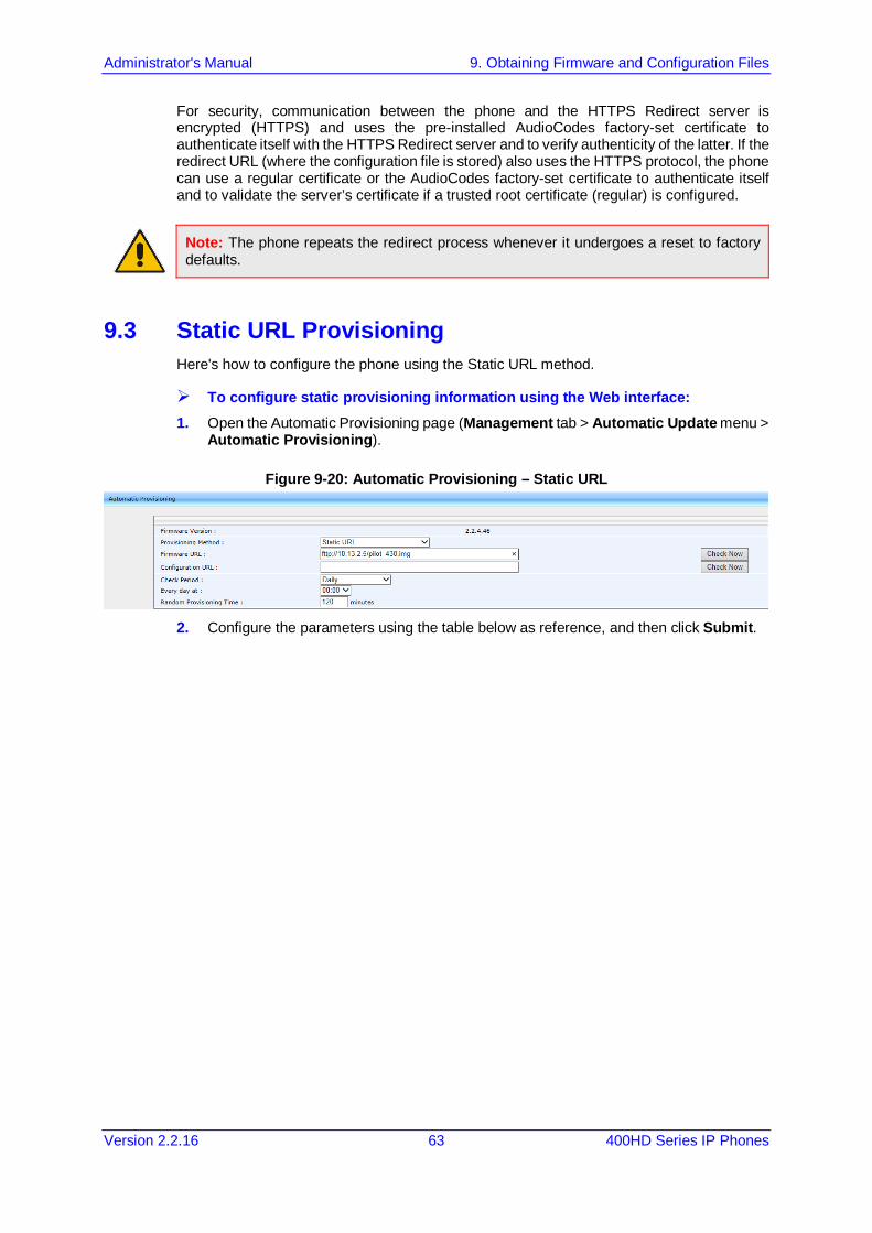
Administrator's Manual 9. Obtaining Firmware and Configuration Files
Version 2.2.16 63 400HD Series IP Phones
For security, communication between the phone and the HTTPS Redirect server is encrypted (HTTPS) and uses the pre-installed AudioCodes factory-set certificate to authenticate itself with the HTTPS Redirect server and to verify authenticity of the latter. If the redirect URL (where the configuration file is stored) also uses the HTTPS protocol, the phone can use a regular certificate or the AudioCodes factory-set certificate to authenticate itself and to validate the server’s certificate if a trusted root certificate (regular) is configured.
Note: The phone repeats the redirect process whenever it undergoes a reset to factory defaults.
9.3 Static URL Provisioning Here's how to configure the phone using the Static URL method.
To configure static provisioning information using the Web interface: 1. Open the Automatic Provisioning page (Management tab > Automatic Update menu >
Automatic Provisioning).
Figure 9-20: Automatic Provisioning – Static URL
2. Configure the parameters using the table below as reference, and then click Submit.
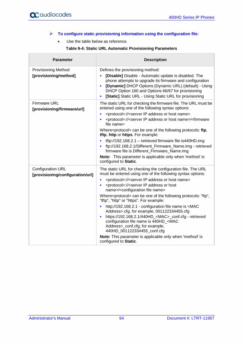
400HD Series IP Phones
Administrator's Manual 64 Document #: LTRT-11957
To configure static provisioning information using the configuration file:
• Use the table below as reference.
Table 9-4: Static URL Automatic Provisioning Parameters
Parameter Description
Provisioning Method [provisioning/method]
Defines the provisioning method: [Disable] Disable - Automatic update is disabled. The
phone attempts to upgrade its firmware and configuration [Dynamic] DHCP Options (Dynamic URL) (default) - Using
DHCP Option 160 and Options 66/67 for provisioning [Static] Static URL - Using Static URL for provisioning
Firmware URL [provisioning/firmware/url]
The static URL for checking the firmware file. The URL must be entered using one of the following syntax options: <protocol>://<server IP address or host name> <protocol>://<server IP address or host name>/<firmware
file name> Where<protocol> can be one of the following protocols: ftp, tftp, http or https. For example: tftp://192.168.2.1 – retrieved firmware file is440HD.img ftp://192.168.2.1/Different_Firmware_Name.img - retrieved
firmware file is Different_Firmware_Name.img Note: This parameter is applicable only when 'method' is configured to Static.
Configuration URL [provisioning/configuration/url]
The static URL for checking the configuration file. The URL must be entered using one of the following syntax options: <protocol>://<server IP address or host name> <protocol>://<server IP address or host
name>/<configuration file name> Where<protocol> can be one of the following protocols: "ftp", "tftp", "http" or "https". For example: http://192.168.2.1 - configuration file name is <MAC
Address>.cfg, for example, 001122334455.cfg https://192.168.2.1/440HD_<MAC>_conf.cfg - retrieved
configuration file name is 440HD_<MAC Address>_conf.cfg, for example, 440HD_001122334455_conf.cfg
Note: This parameter is applicable only when 'method' is configured to Static.
Part III Quick Setup

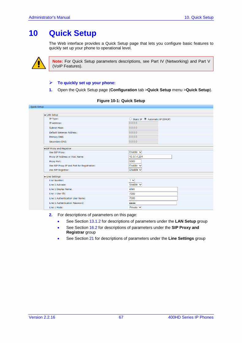
Administrator's Manual 10. Quick Setup
Version 2.2.16 67 400HD Series IP Phones
10 Quick Setup The Web interface provides a Quick Setup page that lets you configure basic features to quickly set up your phone to operational level.
Note: For Quick Setup parameters descriptions, see Part IV (Networking) and Part V (VoIP Features).
To quickly set up your phone: 1. Open the Quick Setup page (Configuration tab >Quick Setup menu >Quick Setup).
Figure 10-1: Quick Setup
2. For descriptions of parameters on this page:
• See Section 13.1.2 for descriptions of parameters under the LAN Setup group • See Section 16.2 for descriptions of parameters under the SIP Proxy and
Registrar group • See Section 21 for descriptions of parameters under the Line Settings group

400HD Series IP Phones
Administrator's Manual 68 Document #: LTRT-11957
This page is intentionally left blank.

Part IV Networking


Administrator's Manual 11. Introduction
Version 2.2.16 71 400HD Series IP Phones
11 Introduction Here's how to configure network settings manually, if required.
Note: By default, the network settings are set for automatic provisioning. However, if you need to change them, you can do so manually, as described in this section.

400HD Series IP Phones
Administrator's Manual 72 Document #: LTRT-11957
This page is intentionally left blank.
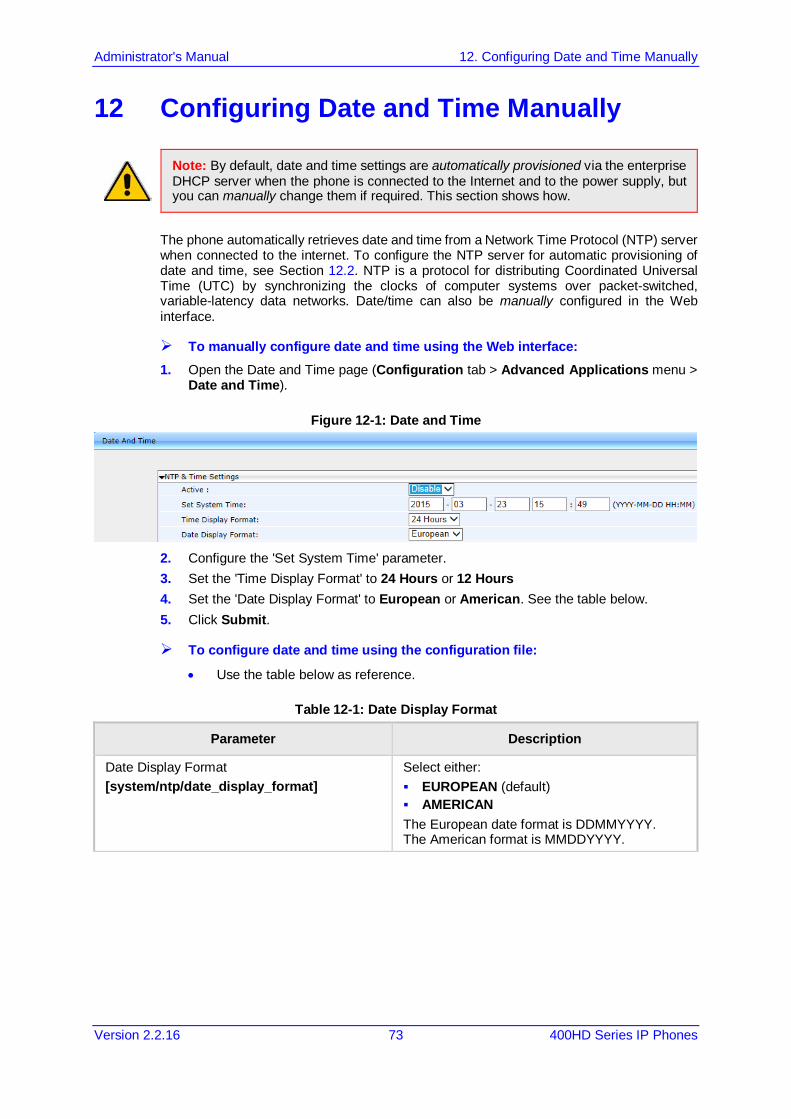
Administrator's Manual 12. Configuring Date and Time Manually
Version 2.2.16 73 400HD Series IP Phones
12 Configuring Date and Time Manually
Note: By default, date and time settings are automatically provisioned via the enterprise DHCP server when the phone is connected to the Internet and to the power supply, but you can manually change them if required. This section shows how.
The phone automatically retrieves date and time from a Network Time Protocol (NTP) server when connected to the internet. To configure the NTP server for automatic provisioning of date and time, see Section 12.2. NTP is a protocol for distributing Coordinated Universal Time (UTC) by synchronizing the clocks of computer systems over packet-switched, variable-latency data networks. Date/time can also be manually configured in the Web interface.
To manually configure date and time using the Web interface: 1. Open the Date and Time page (Configuration tab > Advanced Applications menu >
Date and Time).
Figure 12-1: Date and Time
2. Configure the 'Set System Time' parameter. 3. Set the 'Time Display Format' to 24 Hours or 12 Hours 4. Set the 'Date Display Format' to European or American. See the table below. 5. Click Submit.
To configure date and time using the configuration file:
• Use the table below as reference.
Table 12-1: Date Display Format
Parameter Description
Date Display Format [system/ntp/date_display_format]
Select either: EUROPEAN (default) AMERICAN The European date format is DDMMYYYY. The American format is MMDDYYYY.
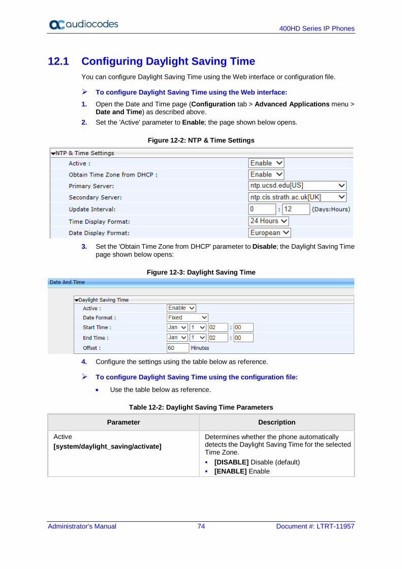
400HD Series IP Phones
Administrator's Manual 74 Document #: LTRT-11957
12.1 Configuring Daylight Saving Time You can configure Daylight Saving Time using the Web interface or configuration file.
To configure Daylight Saving Time using the Web interface: 1. Open the Date and Time page (Configuration tab > Advanced Applications menu >
Date and Time) as described above. 2. Set the 'Active' parameter to Enable; the page shown below opens.
Figure 12-2: NTP & Time Settings
3. Set the 'Obtain Time Zone from DHCP' parameter to Disable; the Daylight Saving Time
page shown below opens:
Figure 12-3: Daylight Saving Time
4. Configure the settings using the table below as reference.
To configure Daylight Saving Time using the configuration file:
• Use the table below as reference.
Table 12-2: Daylight Saving Time Parameters
Parameter Description
Active [system/daylight_saving/activate]
Determines whether the phone automatically detects the Daylight Saving Time for the selected Time Zone. [DISABLE] Disable (default) [ENABLE] Enable
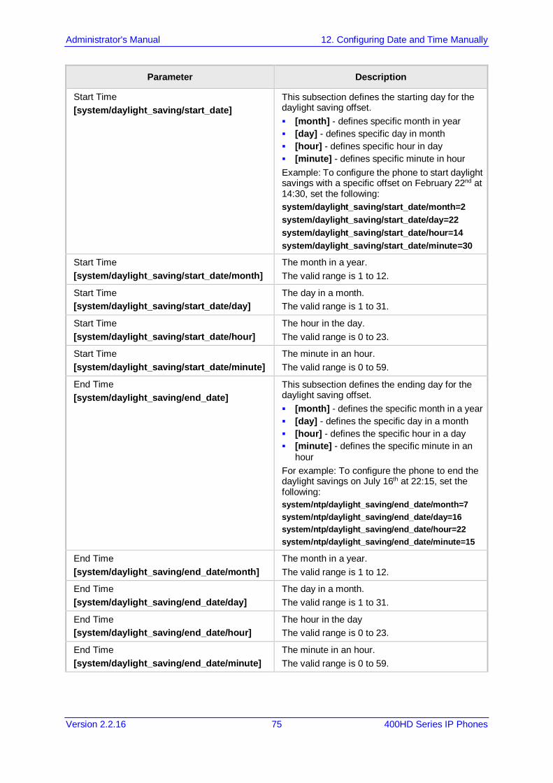
Administrator's Manual 12. Configuring Date and Time Manually
Version 2.2.16 75 400HD Series IP Phones
Parameter Description
Start Time [system/daylight_saving/start_date]
This subsection defines the starting day for the daylight saving offset. [month] - defines specific month in year [day] - defines specific day in month [hour] - defines specific hour in day [minute] - defines specific minute in hour Example: To configure the phone to start daylight savings with a specific offset on February 22nd at 14:30, set the following: system/daylight_saving/start_date/month=2 system/daylight_saving/start_date/day=22 system/daylight_saving/start_date/hour=14 system/daylight_saving/start_date/minute=30
Start Time [system/daylight_saving/start_date/month]
The month in a year. The valid range is 1 to 12.
Start Time [system/daylight_saving/start_date/day]
The day in a month. The valid range is 1 to 31.
Start Time [system/daylight_saving/start_date/hour]
The hour in the day. The valid range is 0 to 23.
Start Time [system/daylight_saving/start_date/minute]
The minute in an hour. The valid range is 0 to 59.
End Time [system/daylight_saving/end_date]
This subsection defines the ending day for the daylight saving offset. [month] - defines the specific month in a year [day] - defines the specific day in a month [hour] - defines the specific hour in a day [minute] - defines the specific minute in an
hour For example: To configure the phone to end the daylight savings on July 16th at 22:15, set the following: system/ntp/daylight_saving/end_date/month=7 system/ntp/daylight_saving/end_date/day=16 system/ntp/daylight_saving/end_date/hour=22 system/ntp/daylight_saving/end_date/minute=15
End Time [system/daylight_saving/end_date/month]
The month in a year. The valid range is 1 to 12.
End Time [system/daylight_saving/end_date/day]
The day in a month. The valid range is 1 to 31.
End Time [system/daylight_saving/end_date/hour]
The hour in the day The valid range is 0 to 23.
End Time [system/daylight_saving/end_date/minute]
The minute in an hour. The valid range is 0 to 59.
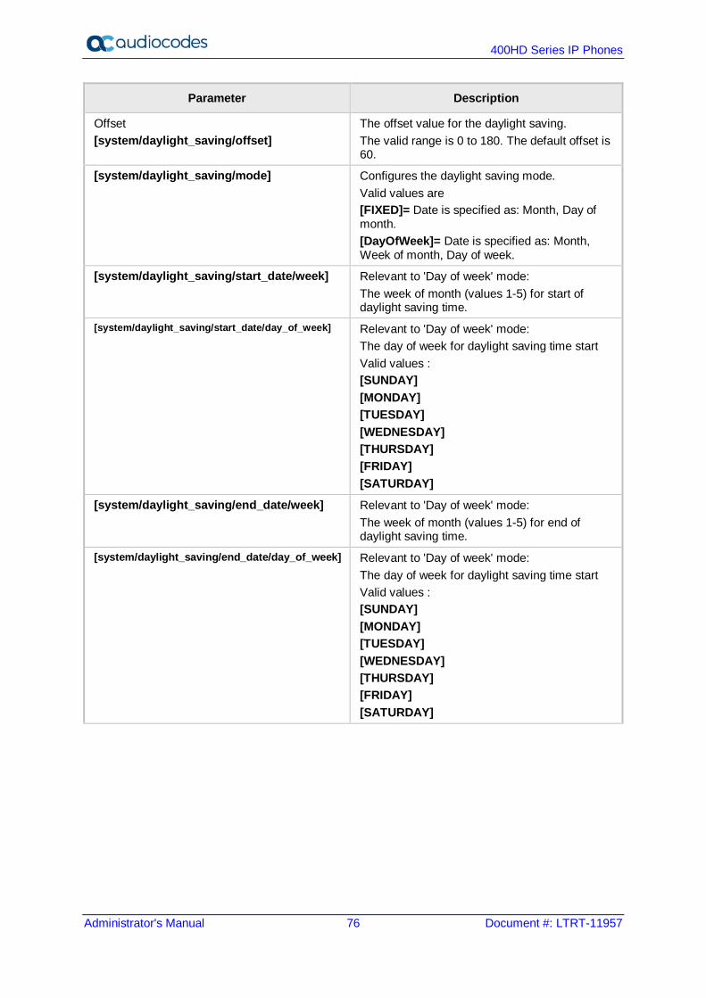
400HD Series IP Phones
Administrator's Manual 76 Document #: LTRT-11957
Parameter Description
Offset [system/daylight_saving/offset]
The offset value for the daylight saving. The valid range is 0 to 180. The default offset is 60.
[system/daylight_saving/mode] Configures the daylight saving mode. Valid values are [FIXED]= Date is specified as: Month, Day of month. [DayOfWeek]= Date is specified as: Month, Week of month, Day of week.
[system/daylight_saving/start_date/week] Relevant to 'Day of week' mode: The week of month (values 1-5) for start of daylight saving time.
[system/daylight_saving/start_date/day_of_week] Relevant to 'Day of week' mode: The day of week for daylight saving time start Valid values : [SUNDAY] [MONDAY] [TUESDAY] [WEDNESDAY] [THURSDAY] [FRIDAY] [SATURDAY]
[system/daylight_saving/end_date/week] Relevant to 'Day of week' mode: The week of month (values 1-5) for end of daylight saving time.
[system/daylight_saving/end_date/day_of_week] Relevant to 'Day of week' mode: The day of week for daylight saving time start Valid values : [SUNDAY] [MONDAY] [TUESDAY] [WEDNESDAY] [THURSDAY] [FRIDAY] [SATURDAY]

Administrator's Manual 12. Configuring Date and Time Manually
Version 2.2.16 77 400HD Series IP Phones
12.2 Configuring the NTP Server The Network Time Protocol (NTP) server can be configured using the Web interface or configuration file. When activated, date and time are automatically obtained from the NTP server.
To configure the NTP server using the Web interface: 1. Open the Date and Time page (Configuration tab > Advanced Applications menu >
Date and Time). 2. Configure the parameters using the table below as reference, and then click Submit.
Figure 12-4: NTP & Time Settings
To configure the NTP server using the configuration file:
• Use the table below as reference.
Table 12-3: NTP Server Parameters
Parameter Description
Active [system/ntp/enabled]
Enables the NTP server from which the phone automatically retrieves the date and time. [0] Disable [1] Enable – obtains the time information
automatically from a configured NTP server (default)
Primary Server [system/ntp/primary_server_address]
Defines the address of the main NTP server (this can be a domain name, for example, tick.nap.com.ar).
Secondary Server [system/ntp/secondary_server_address]
Defines the address of the secondary NTP server.
Update Interval [system/ntp/sync_time]
This sub-section defines how often the phone must perform an update with the NTP server. [days] -defines the number of days [hours] - defines the number of hours For example: To configure the phone to perform an update with an NTP server every 1 day and 6 hours, set the following: system/ntp/sync_time/days=1 system/ntp/sync_time/hours=6
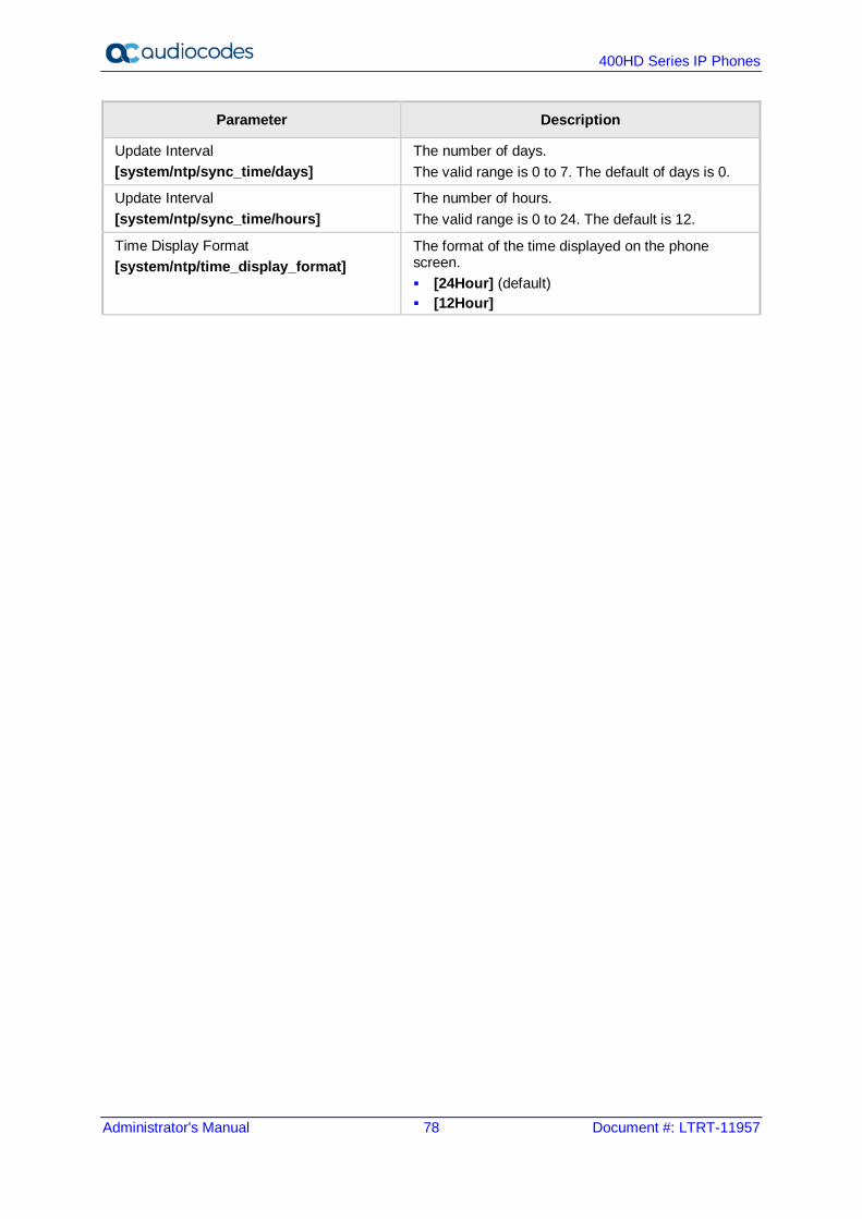
400HD Series IP Phones
Administrator's Manual 78 Document #: LTRT-11957
Parameter Description
Update Interval [system/ntp/sync_time/days]
The number of days. The valid range is 0 to 7. The default of days is 0.
Update Interval [system/ntp/sync_time/hours]
The number of hours. The valid range is 0 to 24. The default is 12.
Time Display Format [system/ntp/time_display_format]
The format of the time displayed on the phone screen. [24Hour] (default) [12Hour]
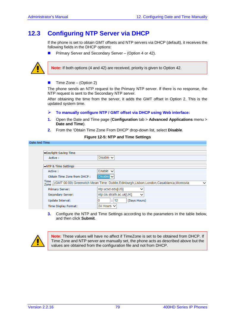
Administrator's Manual 12. Configuring Date and Time Manually
Version 2.2.16 79 400HD Series IP Phones
12.3 Configuring NTP Server via DHCP If the phone is set to obtain GMT offsets and NTP servers via DHCP (default), it receives the following fields in the DHCP options: Primary Server and Secondary Server – (Option 4 or 42).
Note: If both options (4 and 42) are received, priority is given to Option 42.
Time Zone – (Option 2) The phone sends an NTP request to the Primary NTP server. If there is no response, the NTP request is sent to the Secondary NTP server. After obtaining the time from the server, it adds the GMT offset in Option 2. This is the updated system time.
To manually configure NTP / GMT offset via DHCP using Web interface: 1. Open the Date and Time page (Configuration tab > Advanced Applications menu >
Date and Time). 2. From the 'Obtain Time Zone From DHCP' drop-down list, select Disable.
Figure 12-5: NTP and Time Settings
3. Configure the NTP and Time Settings according to the parameters in the table below,
and then click Submit.
Note: These values will have no affect if TimeZone is set to be obtained from DHCP. If Time Zone and NTP server are manually set, the phone acts as described above but the values are obtained from the configuration file and not from DHCP.
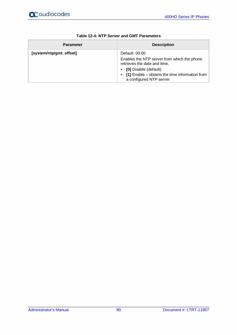
400HD Series IP Phones
Administrator's Manual 80 Document #: LTRT-11957
Table 12-4: NTP Server and GMT Parameters
Parameter Description
[system/ntp/gmt_offset] Default: 00:00 Enables the NTP server from which the phone retrieves the date and time. [0] Disable (default) [1] Enable – obtains the time information from
a configured NTP server
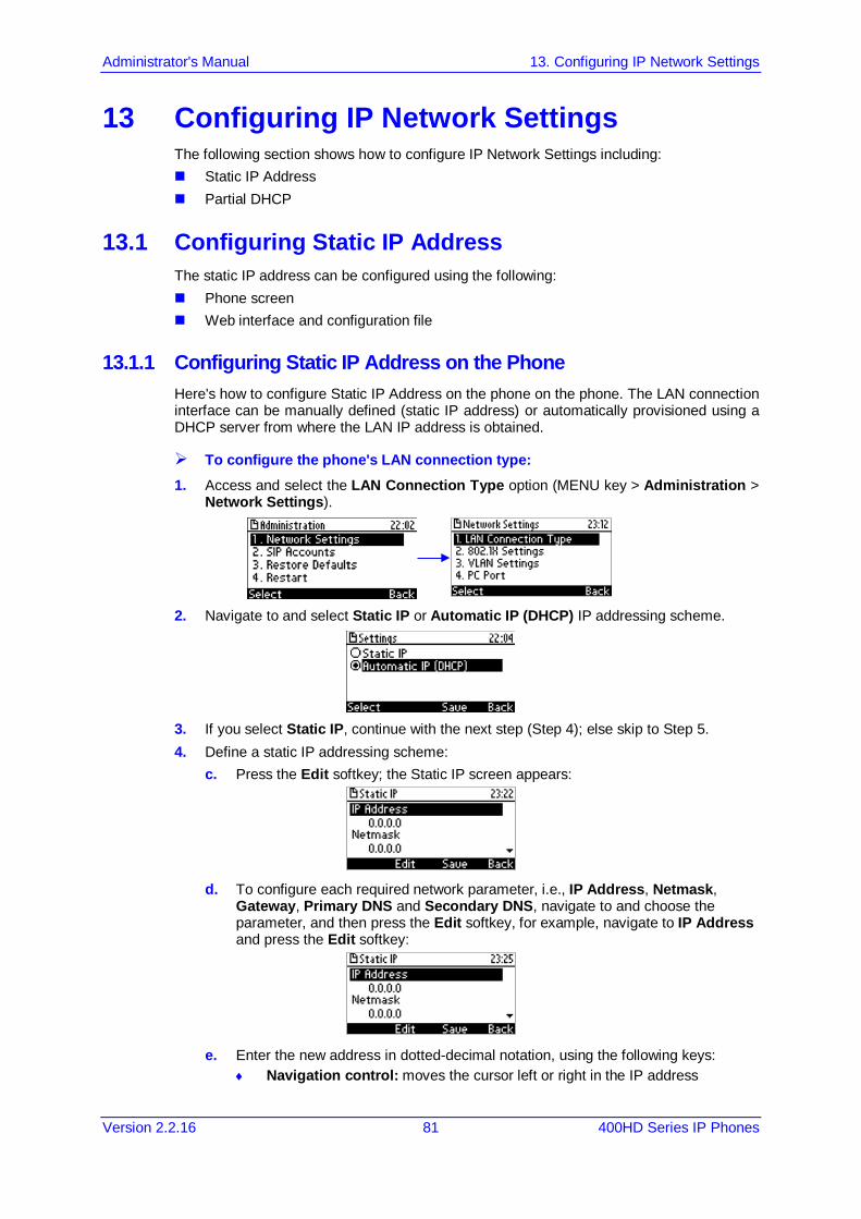
Administrator's Manual 13. Configuring IP Network Settings
Version 2.2.16 81 400HD Series IP Phones
13 Configuring IP Network Settings The following section shows how to configure IP Network Settings including: Static IP Address Partial DHCP
13.1 Configuring Static IP Address The static IP address can be configured using the following: Phone screen Web interface and configuration file
13.1.1 Configuring Static IP Address on the Phone Here's how to configure Static IP Address on the phone on the phone. The LAN connection interface can be manually defined (static IP address) or automatically provisioned using a DHCP server from where the LAN IP address is obtained.
To configure the phone's LAN connection type: 1. Access and select the LAN Connection Type option (MENU key > Administration >
Network Settings).
2. Navigate to and select Static IP or Automatic IP (DHCP) IP addressing scheme.
3. If you select Static IP, continue with the next step (Step 4); else skip to Step 5. 4. Define a static IP addressing scheme:
c. Press the Edit softkey; the Static IP screen appears:
d. To configure each required network parameter, i.e., IP Address, Netmask,
Gateway, Primary DNS and Secondary DNS, navigate to and choose the parameter, and then press the Edit softkey, for example, navigate to IP Address and press the Edit softkey:
e. Enter the new address in dotted-decimal notation, using the following keys:
♦ Navigation control: moves the cursor left or right in the IP address

400HD Series IP Phones
Administrator's Manual 82 Document #: LTRT-11957
♦ Clear softkey: deletes the digit to the left of the cursor. f. Press the Save and then Apply softkey.
5. Press the Save softkey.
13.1.2 Configuring IP Network Settings Here's how to configure IP Network settings using the Web interface or configuration file. The phone's LAN configuration includes defining the method for obtaining an IP address. The phone's IP address can be static whereby the IP address is manually entered, or automatic whereby the IP address is acquired from a DHCP server. For Automatic IP, you can manually define some of the main parameters.
To define the phone's LAN settings using the Web interface: 1. Open the LAN Settings page (Configuration tab > Network Connections menu >
Network Settings).
Figure 13-1: Network Settings
2. Configure the LAN parameters using the table below as reference, and then click
Submit.
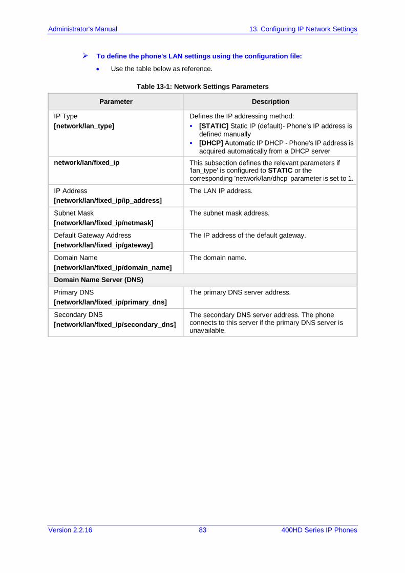
Administrator's Manual 13. Configuring IP Network Settings
Version 2.2.16 83 400HD Series IP Phones
To define the phone's LAN settings using the configuration file:
• Use the table below as reference.
Table 13-1: Network Settings Parameters
Parameter Description
IP Type [network/lan_type]
Defines the IP addressing method: [STATIC] Static IP (default)- Phone's IP address is
defined manually [DHCP] Automatic IP DHCP - Phone's IP address is
acquired automatically from a DHCP server network/lan/fixed_ip This subsection defines the relevant parameters if
'lan_type' is configured to STATIC or the corresponding 'network/lan/dhcp' parameter is set to 1.
IP Address [network/lan/fixed_ip/ip_address]
The LAN IP address.
Subnet Mask [network/lan/fixed_ip/netmask]
The subnet mask address.
Default Gateway Address [network/lan/fixed_ip/gateway]
The IP address of the default gateway.
Domain Name [network/lan/fixed_ip/domain_name]
The domain name.
Domain Name Server (DNS)
Primary DNS [network/lan/fixed_ip/primary_dns]
The primary DNS server address.
Secondary DNS [network/lan/fixed_ip/secondary_dns]
The secondary DNS server address. The phone connects to this server if the primary DNS server is unavailable.
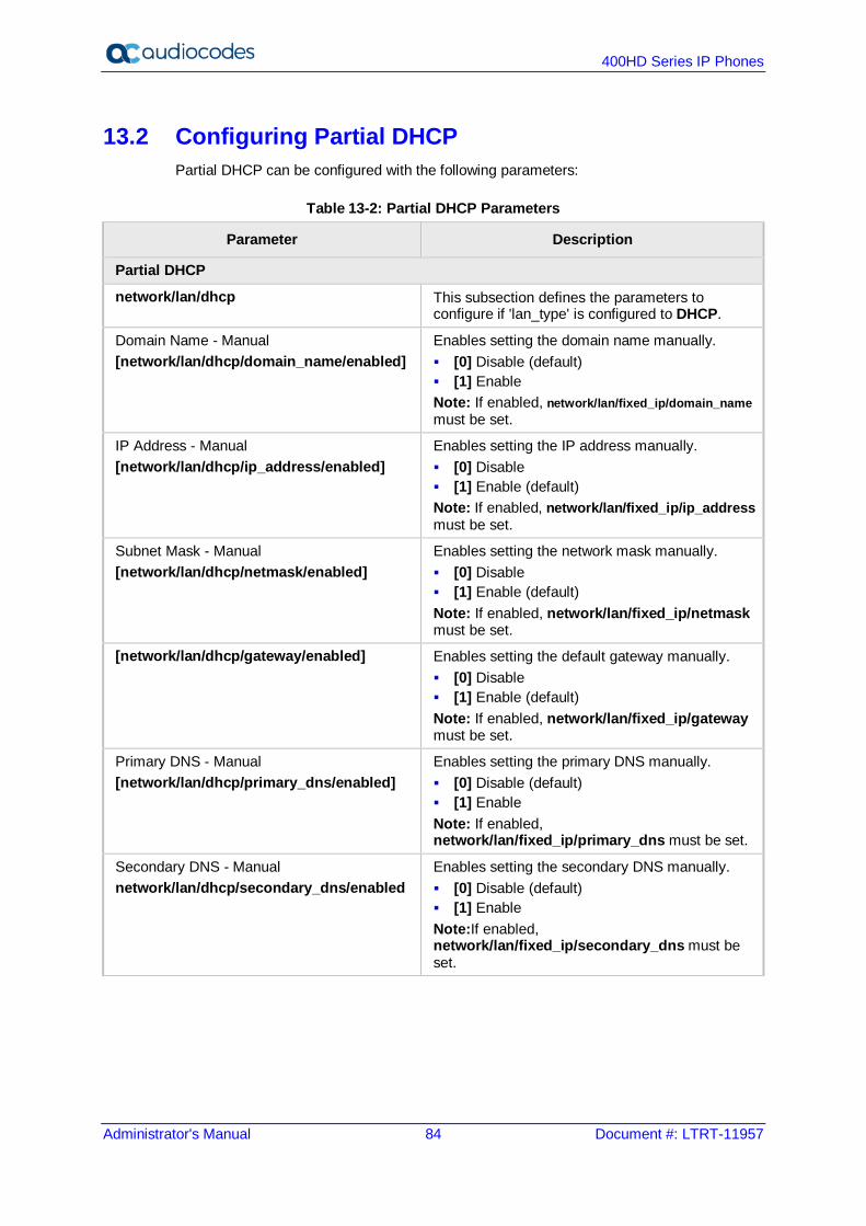
400HD Series IP Phones
Administrator's Manual 84 Document #: LTRT-11957
13.2 Configuring Partial DHCP Partial DHCP can be configured with the following parameters:
Table 13-2: Partial DHCP Parameters
Parameter Description
Partial DHCP
network/lan/dhcp This subsection defines the parameters to configure if 'lan_type' is configured to DHCP.
Domain Name - Manual [network/lan/dhcp/domain_name/enabled]
Enables setting the domain name manually. [0] Disable (default) [1] Enable Note: If enabled, network/lan/fixed_ip/domain_name must be set.
IP Address - Manual [network/lan/dhcp/ip_address/enabled]
Enables setting the IP address manually. [0] Disable [1] Enable (default) Note: If enabled, network/lan/fixed_ip/ip_address must be set.
Subnet Mask - Manual [network/lan/dhcp/netmask/enabled]
Enables setting the network mask manually. [0] Disable [1] Enable (default) Note: If enabled, network/lan/fixed_ip/netmask must be set.
[network/lan/dhcp/gateway/enabled] Enables setting the default gateway manually. [0] Disable [1] Enable (default) Note: If enabled, network/lan/fixed_ip/gateway must be set.
Primary DNS - Manual [network/lan/dhcp/primary_dns/enabled]
Enables setting the primary DNS manually. [0] Disable (default) [1] Enable Note: If enabled, network/lan/fixed_ip/primary_dns must be set.
Secondary DNS - Manual network/lan/dhcp/secondary_dns/enabled
Enables setting the secondary DNS manually. [0] Disable (default) [1] Enable Note:If enabled, network/lan/fixed_ip/secondary_dns must be set.
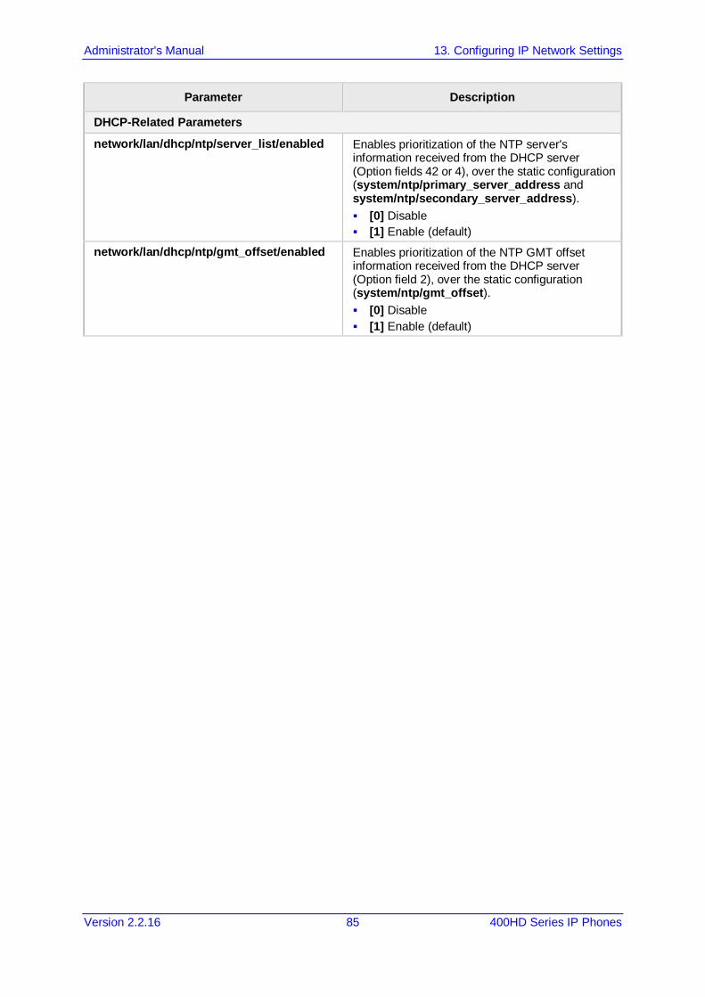
Administrator's Manual 13. Configuring IP Network Settings
Version 2.2.16 85 400HD Series IP Phones
Parameter Description
DHCP-Related Parameters
network/lan/dhcp/ntp/server_list/enabled Enables prioritization of the NTP server's information received from the DHCP server (Option fields 42 or 4), over the static configuration (system/ntp/primary_server_address and system/ntp/secondary_server_address). [0] Disable [1] Enable (default)
network/lan/dhcp/ntp/gmt_offset/enabled Enables prioritization of the NTP GMT offset information received from the DHCP server (Option field 2), over the static configuration (system/ntp/gmt_offset). [0] Disable [1] Enable (default)

400HD Series IP Phones
Administrator's Manual 86 Document #: LTRT-11957
This page is intentionally left blank.

Administrator's Manual 14. Configuring LAN and PC Port Settings
Version 2.2.16 87 400HD Series IP Phones
14 Configuring LAN and PC Port Settings Port settings can be configured using the Web interface or configuration file.
Note: The optional values of the configuration file parameters are enclosed in square brackets while its corresponding Web values are written outside the square brackets, for example, [1] Enable.
To configure the phone's port settings using the Web interface: 1. Open the Network Settings page (Configuration tab > Network Connections menu >
Network Settings).
Figure 14-1: Network Settings - Port Mode
2. Configure the parameters using the table below as reference, and then click Submit.
To define the phone's port settings using the configuration file:
• Use the table below as reference.
Table 14-1: Port Settings
Parameter Description
LAN Port Mode [network/lan/port_mode]
Sets the LAN port mode. Valid values are : [AUTOMATIC] = Auto negotiation. [FULL_10] = 10Mbps + full duplex [FULL_100] = 100Mbps + half duplex [HALF_10] = 10Mbps + full duplex [HALF_100] = 100Mbps + half duplex [FULL _ 1Gbps] = 1 Gbit/s port + full duplex
PC Port Mode [network/pc/port_mode]
Sets the computer port mode. See valid values above.

400HD Series IP Phones
Administrator's Manual 88 Document #: LTRT-11957
This page is intentionally left blank.
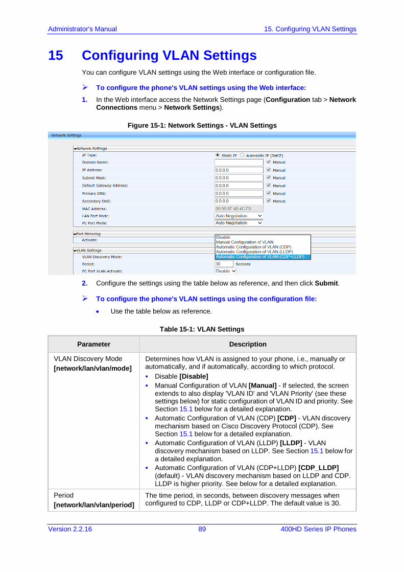
Administrator's Manual 15. Configuring VLAN Settings
Version 2.2.16 89 400HD Series IP Phones
15 Configuring VLAN Settings You can configure VLAN settings using the Web interface or configuration file.
To configure the phone's VLAN settings using the Web interface: 1. In the Web interface access the Network Settings page (Configuration tab > Network
Connections menu > Network Settings).
Figure 15-1: Network Settings - VLAN Settings
2. Configure the settings using the table below as reference, and then click Submit.
To configure the phone's VLAN settings using the configuration file:
• Use the table below as reference.
Table 15-1: VLAN Settings
Parameter Description
VLAN Discovery Mode [network/lan/vlan/mode]
Determines how VLAN is assigned to your phone, i.e., manually or automatically, and if automatically, according to which protocol. Disable [Disable] Manual Configuration of VLAN [Manual] - If selected, the screen
extends to also display 'VLAN ID' and 'VLAN Priority' (see these settings below) for static configuration of VLAN ID and priority. See Section 15.1 below for a detailed explanation.
Automatic Configuration of VLAN (CDP) [CDP] - VLAN discovery mechanism based on Cisco Discovery Protocol (CDP). See Section 15.1 below for a detailed explanation.
Automatic Configuration of VLAN (LLDP) [LLDP] - VLAN discovery mechanism based on LLDP. See Section 15.1 below for a detailed explanation.
Automatic Configuration of VLAN (CDP+LLDP) [CDP_LLDP] (default) - VLAN discovery mechanism based on LLDP and CDP. LLDP is higher priority. See below for a detailed explanation.
Period [network/lan/vlan/period]
The time period, in seconds, between discovery messages when configured to CDP, LLDP or CDP+LLDP. The default value is 30.
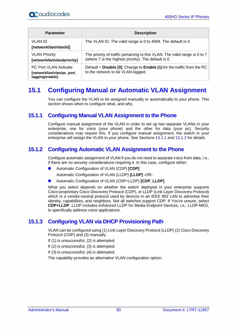
400HD Series IP Phones
Administrator's Manual 90 Document #: LTRT-11957
Parameter Description
VLAN ID [network/lan/vlan/id]
The VLAN ID. The valid range is 0 to 4094. The default is 0.
VLAN Priority [network/lan/vlan/priority]
The priority of traffic pertaining to this VLAN. The valid range is 0 to 7 (where 7 is the highest priority). The default is 0.
PC Port VLAN Activate [network/lan/vlan/pc_port_ tagging/enable]
Default = Disable [0]. Change to Enable (1) for the traffic from the PC to the network to be VLAN-tagged.
15.1 Configuring Manual or Automatic VLAN Assignment You can configure the VLAN to be assigned manually or automatically to your phone. This section shows when to configure what, and why.
15.1.1 Configuring Manual VLAN Assignment to the Phone Configure manual assignment of the VLAN in order to set up two separate VLANs in your enterprise, one for voice (your phone) and the other for data (your pc). Security considerations may require this. If you configure manual assignment, the switch in your enterprise will assign the VLAN to your phone. See Sections 13.1.1 and 13.1.2 for details.
15.1.2 Configuring Automatic VLAN Assignment to the Phone Configure automatic assignment of VLAN if you do not need to separate voice from data, i.e., if there are no security considerations requiring it. In this case, configure either: Automatic Configuration of VLAN (CDP) [CDP]
Automatic Configuration of VLAN (LLDP) [LLDP] -OR- Automatic Configuration of VLAN (CDP+LLDP) [CDP_LLDP] What you select depends on whether the switch deployed in your enterprise supports Cisco-proprietary Cisco Discovery Protocol (CDP), or LLDP (Link Layer Discovery Protocol) which is a vendor-neutral protocol used by devices in an IEEE 802 LAN to advertise their identity, capabilities, and neighbors. Not all switches support CDP. If You're unsure, select CDP+LLDP. LLDP includes enhanced LLDP for Media Endpoint Devices, i.e., LLDP-MED, to specifically address voice applications.
15.1.3 Configuring VLAN via DHCP Provisioning Path VLAN can be configured using (1) Link Layer Discovery Protocol (LLDP) (2) Cisco Discovery Protocol (CDP) and (3) manually. If (1) is unsuccessful, (2) is attempted. If (2) is unsuccessful, (3) is attempted. If (3) is unsuccessful, (4) is attempted. The capability provides an alternative VLAN configuration option.
B
Part V VoIP Settings

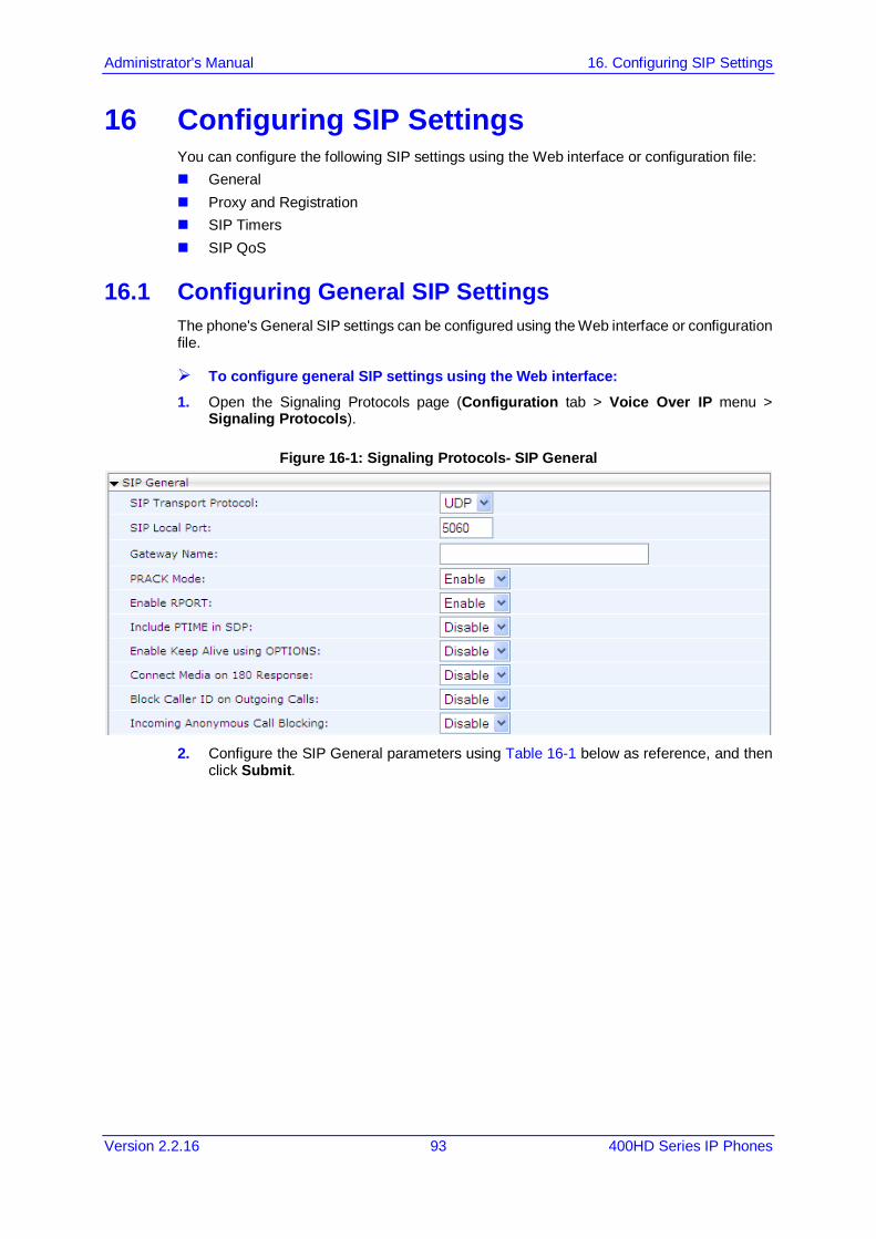
Administrator's Manual 16. Configuring SIP Settings
Version 2.2.16 93 400HD Series IP Phones
16 Configuring SIP Settings You can configure the following SIP settings using the Web interface or configuration file: General Proxy and Registration SIP Timers SIP QoS
16.1 Configuring General SIP Settings The phone's General SIP settings can be configured using the Web interface or configuration file.
To configure general SIP settings using the Web interface: 1. Open the Signaling Protocols page (Configuration tab > Voice Over IP menu >
Signaling Protocols).
Figure 16-1: Signaling Protocols- SIP General
2. Configure the SIP General parameters using Table 16-1 below as reference, and then
click Submit.

400HD Series IP Phones
Administrator's Manual 94 Document #: LTRT-11957
To configure General SIP parameters using the configuration file:
• Use the table below as reference.
Table 16-1: SIP General Parameters
Parameter Description
SIP Transport Protocol [voip/signalling/sip/transport_protocol]
Determines the transport layer for outgoing SIP calls initiated by the phone. [UDP] UDP (default) [TCP] TCP [TLS] TLS
TLS Port [voip/signalling/sip/tls_port]
Defines the local TLS SIP port for SIP messages. The valid range is 1024 to 65535. The default value is 5061.
[voip/signalling/sip/enable_sips] Relevant for TLS only, if enabled, the request URI prefix will be “sips:” otherwise, the prefix will be “sip:”
[voip/signalling/sip/subs_no_notify_timer] Indicates the maximum time (in milliseconds) that a subscription waits from receiving 2xx response for a SUBSCRIBE request, until receiving the first NOTIFY request. If the timer expires, the subscription will be terminated.
SIP Local Port [voip/signalling/sip/port]
Defines the local SIP port (UDP or TCP) for SIP messages. The valid range is 1024 to 65535. The default value is 5060.
Gateway Name [voip/signalling/sip/proxy_gateway]
Assigns a name to the phone. The name is used as the host part of the SIP URI in the From header. Note: Ensure that the name you choose
is the one with which the Proxy is configured to identify the phone.
If not specified, the phone's IP address is used (default).
PRACK Mode [voip/signalling/sip/prack/enabled]
Determines whether the phone sends PRACK (Provisional Acknowledgment) messages upon receipt of 1xx SIP reliable responses. [0] Disable [1] Enable (default)
Enable RPORT [voip/signalling/sip/rport/enabled]
Determines whether the phone adds the 'rport' parameter to the relevant SIP message (in the SIP Via header). [0] Disable (default) [1] Enable

Administrator's Manual 16. Configuring SIP Settings
Version 2.2.16 95 400HD Series IP Phones
Parameter Description
Include PTIME in SDP [voip/signalling/sip/sdp_include_ptime]
Determines whether the phone adds the PTIME parameter to the SDP message body. [0] Disable (default) [1] Enable
Enable Keep Alive using OPTIONS [voip/signalling/sip/keepalive_options/enabled]
Determines whether keep-alive is performed using SIP OPTIONS messages sent to the Proxy. [0] Disable (default) [1] Enable
Keep Alive Period [voip/signalling/sip/keepalive_options/timeout]
Defines the Proxy keep-alive time interval (in seconds) between Keep-Alive messages. The valid range is 0 to 86400. The
default value is 300. Connect Media on 180 Response [voip/signalling/sip/connect_media_on_180]
Determines whether the media is connected upon receipt of SIP 180, 183, or 200 messages. When the parameter is disabled, media is connected upon receipt of 183 and 200 messages only. [0] Disable (default) [1] Enable
Block Caller ID on Outgoing Calls [voip/signalling/sip/block_callerid_on_outgoing_calls]
Can be configured only if the BroadSoft BroadWorks application server is used. When enabled, the outgoing INVITE message is sent with an anonymous From header and P-Asserted-Identityheader. [0] Disable (default) [1] Enable For example: FROMheader contains
anonymous URI: From: "Anonymous" sip:[email protected]
P-Asserted-Identityheader: P-Asserted-Identity: "1001" [email protected]
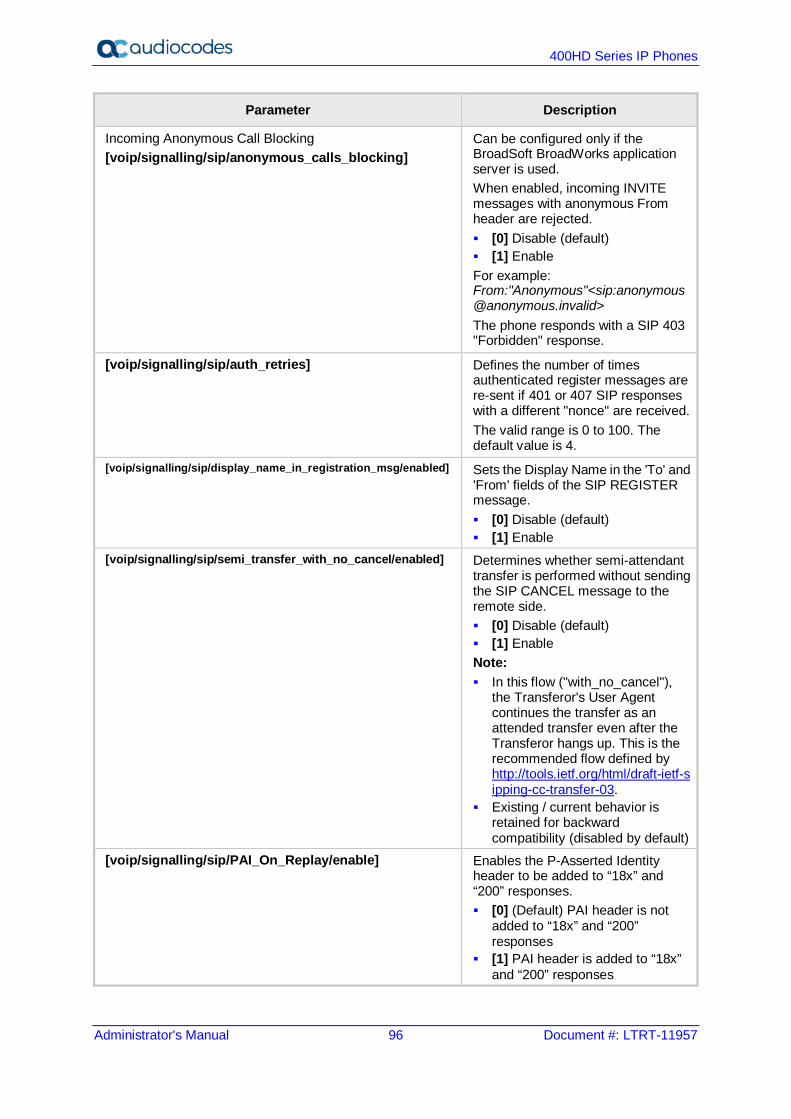
400HD Series IP Phones
Administrator's Manual 96 Document #: LTRT-11957
Parameter Description
Incoming Anonymous Call Blocking [voip/signalling/sip/anonymous_calls_blocking]
Can be configured only if the BroadSoft BroadWorks application server is used. When enabled, incoming INVITE messages with anonymous From header are rejected. [0] Disable (default) [1] Enable For example: From:"Anonymous"<sip:[email protected]> The phone responds with a SIP 403 "Forbidden" response.
[voip/signalling/sip/auth_retries] Defines the number of times authenticated register messages are re-sent if 401 or 407 SIP responses with a different "nonce" are received. The valid range is 0 to 100. The default value is 4.
[voip/signalling/sip/display_name_in_registration_msg/enabled] Sets the Display Name in the 'To' and 'From' fields of the SIP REGISTER message. [0] Disable (default) [1] Enable
[voip/signalling/sip/semi_transfer_with_no_cancel/enabled] Determines whether semi-attendant transfer is performed without sending the SIP CANCEL message to the remote side. [0] Disable (default) [1] Enable Note: In this flow ("with_no_cancel"),
the Transferor's User Agent continues the transfer as an attended transfer even after the Transferor hangs up. This is the recommended flow defined by http://tools.ietf.org/html/draft-ietf-sipping-cc-transfer-03.
Existing / current behavior is retained for backward compatibility (disabled by default)
[voip/signalling/sip/PAI_On_Replay/enable] Enables the P-Asserted Identity header to be added to “18x” and “200” responses. [0] (Default) PAI header is not
added to “18x” and “200” responses
[1] PAI header is added to “18x” and “200” responses
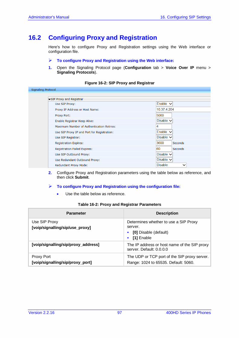
Administrator's Manual 16. Configuring SIP Settings
Version 2.2.16 97 400HD Series IP Phones
16.2 Configuring Proxy and Registration Here's how to configure Proxy and Registration settings using the Web interface or configuration file.
To configure Proxy and Registration using the Web interface: 1. Open the Signaling Protocol page (Configuration tab > Voice Over IP menu >
Signaling Protocols).
Figure 16-2: SIP Proxy and Registrar
2. Configure Proxy and Registration parameters using the table below as reference, and
then click Submit.
To configure Proxy and Registration using the configuration file:
• Use the table below as reference.
Table 16-2: Proxy and Registrar Parameters
Parameter Description
Use SIP Proxy [voip/signalling/sip/use_proxy]
Determines whether to use a SIP Proxy server. [0] Disable (default) [1] Enable
[voip/signalling/sip/proxy_address] The IP address or host name of the SIP proxy server. Default: 0.0.0.0
Proxy Port [voip/signalling/sip/proxy_port]
The UDP or TCP port of the SIP proxy server. Range: 1024 to 65535. Default: 5060.

400HD Series IP Phones
Administrator's Manual 98 Document #: LTRT-11957
Parameter Description
Enable Registrar Keep Alive [voip/signalling/sip/registrar_ka/enabled]
Determines whether to use the registration keep-alive mechanism based on SIP OPTION messages. [0] Disable (default) [1] Enable Note: If there is no response from the server, the
timeout for re-registering is automatically reduced to a user-defined value (voip/signalling/sip/registration_failed_timeout)
When the phone re-registers, the keep-alive messages are re-sent periodically.
Registrar Keep Alive Period [voip/signalling/sip/registrar_ka/timeout]
Defines the registration keep-alive time interval (in seconds) between Keep-Alive messages. Range: 40 to 65536. Default: 60.
Maximum Number of Authentication Retries [voip/signalling/sip/proxy_timeout]
The SIP proxy server registration timeout (in seconds). Range: 0 to 86400. Default: 3600.
Use SIP Proxy IP and Port for Registration [voip/signalling/sip/use_proxy_ip_port_for_registrar]
Determines whether to use the SIP proxy's IP address and port for registration. When enabled, there is no need to configure the address of the registrar separately. [0] Disable (default) [1] Enable
Use SIP Registrar [voip/signalling/sip/sip_registrar/enabled]
Determines whether the phone registers to a separate SIP Registrar server. [0] Disable (default) [1] Enable
Registrar IP Address or Host Name [voip/signalling/sip/sip_registrar/addr]
[Only displayed if the 'Use SIP Registrar' parameter is enabled.] The IP address or host name of the Registrar server. Default: 0.0.0.0
Registrar Port [voip/signalling/sip/sip_registrar/port]
[Only displayed if the 'Use SIP Registrar' parameter is enabled.] The UDP or TCP port of the Registrar server. Range: 1024 to 65535. Default: 5060.
Registration Expires [voip/signalling/sip/registration_failed_timeout]
If registration fails, this parameter determines the interval between the register messages periodically sent until successful registration. Range: 1 to 86400. Default: 3600.
Registration Failed Expires [voip/signalling/sip/registration_failed_timeout]
If registration fails, this parameter determines the interval between the register messages periodically sent until successful registration. Range: 1 to 86400. Default: 300.
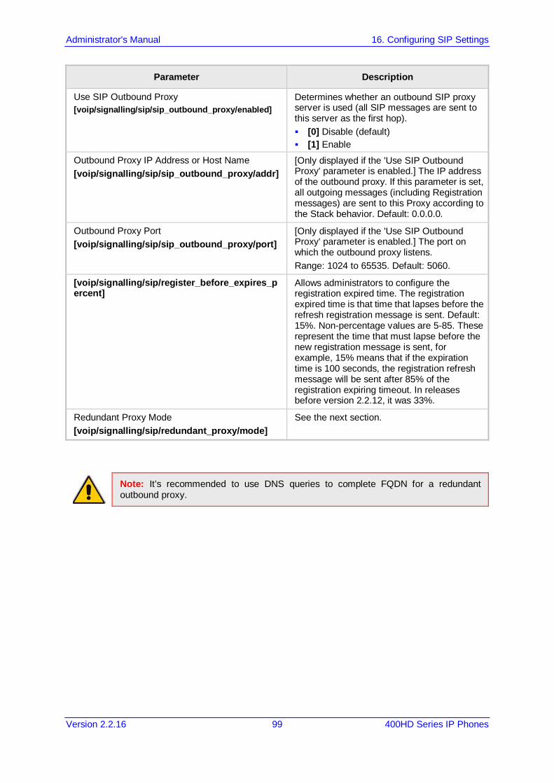
Administrator's Manual 16. Configuring SIP Settings
Version 2.2.16 99 400HD Series IP Phones
Parameter Description
Use SIP Outbound Proxy [voip/signalling/sip/sip_outbound_proxy/enabled]
Determines whether an outbound SIP proxy server is used (all SIP messages are sent to this server as the first hop). [0] Disable (default) [1] Enable
Outbound Proxy IP Address or Host Name [voip/signalling/sip/sip_outbound_proxy/addr]
[Only displayed if the 'Use SIP Outbound Proxy' parameter is enabled.] The IP address of the outbound proxy. If this parameter is set, all outgoing messages (including Registration messages) are sent to this Proxy according to the Stack behavior. Default: 0.0.0.0.
Outbound Proxy Port [voip/signalling/sip/sip_outbound_proxy/port]
[Only displayed if the 'Use SIP Outbound Proxy' parameter is enabled.] The port on which the outbound proxy listens. Range: 1024 to 65535. Default: 5060.
[voip/signalling/sip/register_before_expires_percent]
Allows administrators to configure the registration expired time. The registration expired time is that time that lapses before the refresh registration message is sent. Default: 15%. Non-percentage values are 5-85. These represent the time that must lapse before the new registration message is sent, for example, 15% means that if the expiration time is 100 seconds, the registration refresh message will be sent after 85% of the registration expiring timeout. In releases before version 2.2.12, it was 33%.
Redundant Proxy Mode [voip/signalling/sip/redundant_proxy/mode]
See the next section.
Note: It’s recommended to use DNS queries to complete FQDN for a redundant outbound proxy.
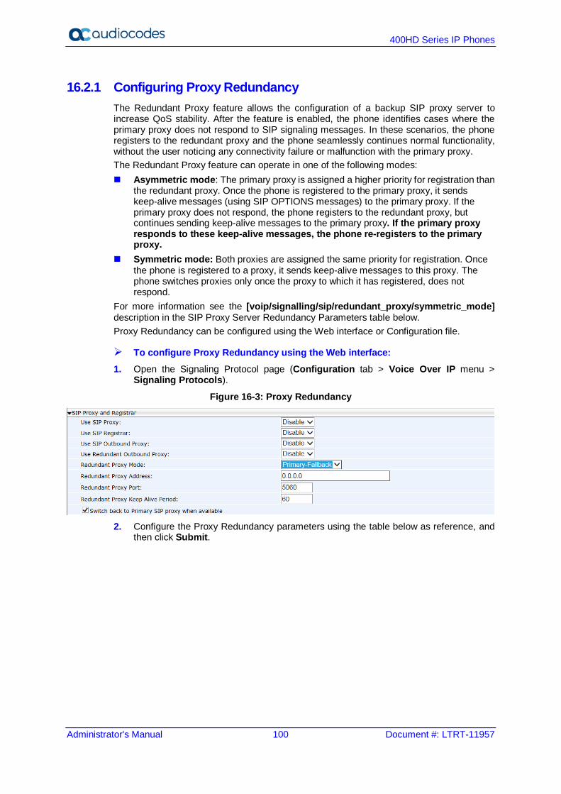
400HD Series IP Phones
Administrator's Manual 100 Document #: LTRT-11957
16.2.1 Configuring Proxy Redundancy The Redundant Proxy feature allows the configuration of a backup SIP proxy server to increase QoS stability. After the feature is enabled, the phone identifies cases where the primary proxy does not respond to SIP signaling messages. In these scenarios, the phone registers to the redundant proxy and the phone seamlessly continues normal functionality, without the user noticing any connectivity failure or malfunction with the primary proxy. The Redundant Proxy feature can operate in one of the following modes: Asymmetric mode: The primary proxy is assigned a higher priority for registration than
the redundant proxy. Once the phone is registered to the primary proxy, it sends keep-alive messages (using SIP OPTIONS messages) to the primary proxy. If the primary proxy does not respond, the phone registers to the redundant proxy, but continues sending keep-alive messages to the primary proxy. If the primary proxy responds to these keep-alive messages, the phone re-registers to the primary proxy.
Symmetric mode: Both proxies are assigned the same priority for registration. Once the phone is registered to a proxy, it sends keep-alive messages to this proxy. The phone switches proxies only once the proxy to which it has registered, does not respond.
For more information see the [voip/signalling/sip/redundant_proxy/symmetric_mode] description in the SIP Proxy Server Redundancy Parameters table below. Proxy Redundancy can be configured using the Web interface or Configuration file.
To configure Proxy Redundancy using the Web interface: 1. Open the Signaling Protocol page (Configuration tab > Voice Over IP menu >
Signaling Protocols).
Figure 16-3: Proxy Redundancy
2. Configure the Proxy Redundancy parameters using the table below as reference, and
then click Submit.
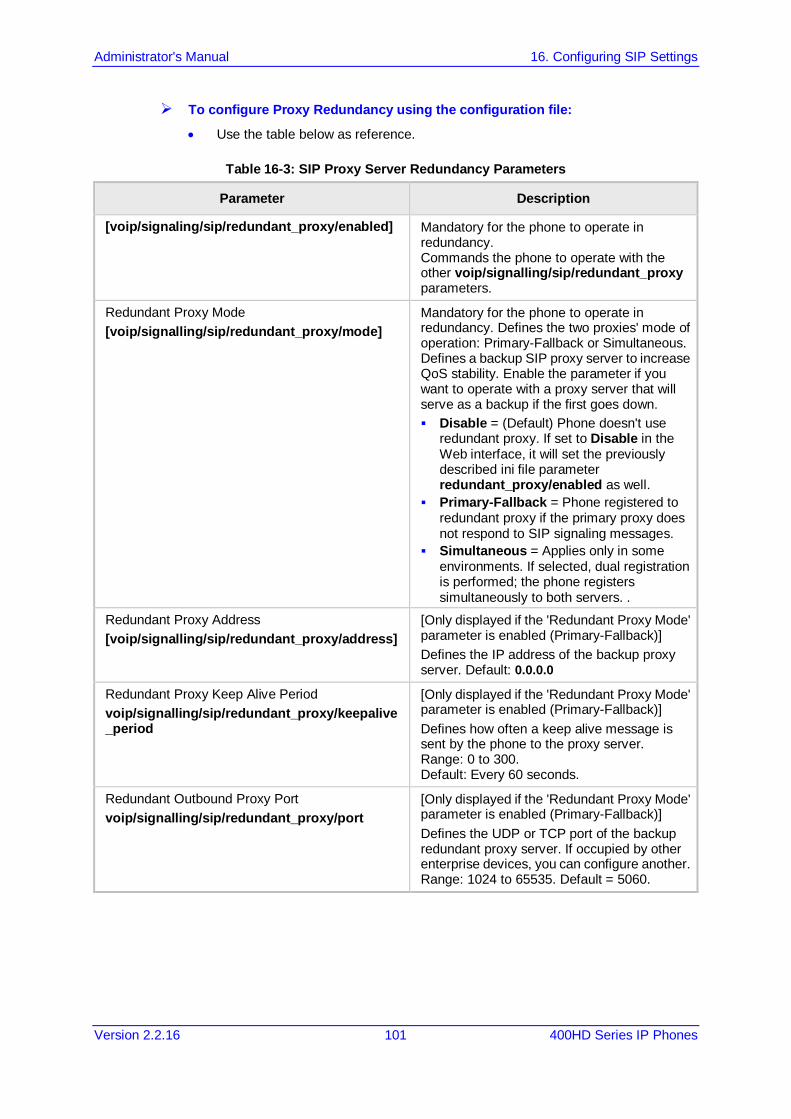
Administrator's Manual 16. Configuring SIP Settings
Version 2.2.16 101 400HD Series IP Phones
To configure Proxy Redundancy using the configuration file:
• Use the table below as reference.
Table 16-3: SIP Proxy Server Redundancy Parameters
Parameter Description
[voip/signaling/sip/redundant_proxy/enabled] Mandatory for the phone to operate in redundancy. Commands the phone to operate with the other voip/signalling/sip/redundant_proxy parameters.
Redundant Proxy Mode [voip/signalling/sip/redundant_proxy/mode]
Mandatory for the phone to operate in redundancy. Defines the two proxies' mode of operation: Primary-Fallback or Simultaneous. Defines a backup SIP proxy server to increase QoS stability. Enable the parameter if you want to operate with a proxy server that will serve as a backup if the first goes down. Disable = (Default) Phone doesn't use
redundant proxy. If set to Disable in the Web interface, it will set the previously described ini file parameter redundant_proxy/enabled as well.
Primary-Fallback = Phone registered to redundant proxy if the primary proxy does not respond to SIP signaling messages.
Simultaneous = Applies only in some environments. If selected, dual registration is performed; the phone registers simultaneously to both servers. .
Redundant Proxy Address [voip/signalling/sip/redundant_proxy/address]
[Only displayed if the 'Redundant Proxy Mode' parameter is enabled (Primary-Fallback)] Defines the IP address of the backup proxy server. Default: 0.0.0.0
Redundant Proxy Keep Alive Period voip/signalling/sip/redundant_proxy/keepalive_period
[Only displayed if the 'Redundant Proxy Mode' parameter is enabled (Primary-Fallback)] Defines how often a keep alive message is sent by the phone to the proxy server. Range: 0 to 300. Default: Every 60 seconds.
Redundant Outbound Proxy Port voip/signalling/sip/redundant_proxy/port
[Only displayed if the 'Redundant Proxy Mode' parameter is enabled (Primary-Fallback)] Defines the UDP or TCP port of the backup redundant proxy server. If occupied by other enterprise devices, you can configure another. Range: 1024 to 65535. Default = 5060.
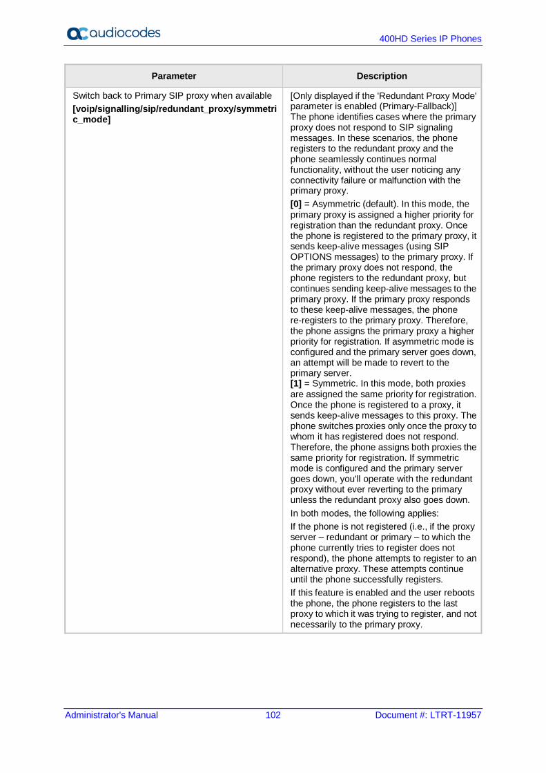
400HD Series IP Phones
Administrator's Manual 102 Document #: LTRT-11957
Parameter Description
Switch back to Primary SIP proxy when available [voip/signalling/sip/redundant_proxy/symmetric_mode]
[Only displayed if the 'Redundant Proxy Mode' parameter is enabled (Primary-Fallback)] The phone identifies cases where the primary proxy does not respond to SIP signaling messages. In these scenarios, the phone registers to the redundant proxy and the phone seamlessly continues normal functionality, without the user noticing any connectivity failure or malfunction with the primary proxy. [0] = Asymmetric (default). In this mode, the primary proxy is assigned a higher priority for registration than the redundant proxy. Once the phone is registered to the primary proxy, it sends keep-alive messages (using SIP OPTIONS messages) to the primary proxy. If the primary proxy does not respond, the phone registers to the redundant proxy, but continues sending keep-alive messages to the primary proxy. If the primary proxy responds to these keep-alive messages, the phone re-registers to the primary proxy. Therefore, the phone assigns the primary proxy a higher priority for registration. If asymmetric mode is configured and the primary server goes down, an attempt will be made to revert to the primary server. [1] = Symmetric. In this mode, both proxies are assigned the same priority for registration. Once the phone is registered to a proxy, it sends keep-alive messages to this proxy. The phone switches proxies only once the proxy to whom it has registered does not respond. Therefore, the phone assigns both proxies the same priority for registration. If symmetric mode is configured and the primary server goes down, you'll operate with the redundant proxy without ever reverting to the primary unless the redundant proxy also goes down. In both modes, the following applies: If the phone is not registered (i.e., if the proxy server – redundant or primary – to which the phone currently tries to register does not respond), the phone attempts to register to an alternative proxy. These attempts continue until the phone successfully registers. If this feature is enabled and the user reboots the phone, the phone registers to the last proxy to which it was trying to register, and not necessarily to the primary proxy.

Administrator's Manual 16. Configuring SIP Settings
Version 2.2.16 103 400HD Series IP Phones
16.2.2 Device Registration Failover/Failback
16.2.2.1 Failover This feature enables a secondary server to take over the functions of the primary server on the enterprise network, if SIP communication between the SIP access device and the primary proxy server is blocked or delayed or the primary server isn't available. No phone functionality is lost when the secondary server takes over.
Note:
• For failover to function, the Proxy DNS server must be configured with a list of the names of the proxies, in order and priority, i.e, SRV record. Before the phone tries to register, it performs an NAPTR / SRV query (see the table below for an explanation of these). The DNS server send a prioritized list. The phone sends a Registration request to the first SIP server; if it isn’t responsive in n time retries (i.e., 'outgoing_request_no_response_timeout' parameter), it goes to the second, etc., until it gets a response.
• SIP Proxy/Outbound Proxy must be configured as the host name.
To configure failover using the configuration file:
• Use the table below as reference.
Table 16-4: Device Registration Failover Parameters
Parameter Description
SIP Transport Protocol [voip/signalling/sip/transport_protocol]
Either: UDP (default) TCP TLS encryption In the SIP protocol, Name Authority Pointers (NAPTRs) are used to map servers and user addresses. Combined with Service Records (SRVs), they enable determining the service types available for a name, the name to use for an SRV lookup, and the port and 'A' DNS records to use to find the IP for the service.
[voip/signalling/sip/outgoing_request_no_response_timeout_ms] This is the timeout, in milliseconds, that lapses until the phone failovers to the secondary proxy. Default: 32000
Outbound Proxy IP Address or Host Name Configure this parameter as an SRV host name.
Outbound Proxy Port [voip/signalling/sip/sip_outbound_proxy/port]
Configure a value of 65535 for this parameter. Configure the parameter when you're using an Outbound Proxy. Either configure this parameter or the parameter 'Proxy Port'.

400HD Series IP Phones
Administrator's Manual 104 Document #: LTRT-11957
Parameter Description
Proxy IP Address or Host Name Configure this parameter as an SRV host name.
Proxy Port [voip/signalling/sip/proxy_port]
Configure a value of 65535 for this parameter. Configure the parameter when you're using a regular Proxy server. Either configure this parameter or the parameter 'Outbound Proxy Port'.
Registrar Port [voip/signalling/sip/sip_registrar/port]
Configure this parameter when you're using a regular Proxy server.
16.2.2.2 Failback
To configure failback using the configuration file:
• Use the table below as reference.
Table 16-5: Device Registration Failback Parameter
Parameter Description
[voip/signalling/sip/failback_retry_timeout] [Only applies to BroadSoft]. Applies only if you're operating with the DNS mode of failover, i.e., with a DNS server. [0] Disable (default) – it'll never try to
access back to the first one. [n] Time, in seconds, that must lapse
before failback is performed.

Administrator's Manual 16. Configuring SIP Settings
Version 2.2.16 105 400HD Series IP Phones
16.3 Configuring a Line Here's how to configure a line.
Note: The Web interface page of the 440HD / 430HD phone are shown here. The Web pages of the 420HD / 405/405HD phones are identical, except:
• on the 420HD/405/405HD phones, 'Line Mode' is not supported • on the 420HD/405/405HD phones, 'Label' is supported • on the 420HD/405/405HD phones, two lines can be configured; on the 430HD/440HD
phones, six lines can be configured.
To configure a line using the Web interface: 1. Open the Line Settings page (Configuration > Voice Over IP > Line Settings):
Figure 16-4: Line Settings
2. Configure Line Mode using the table below as reference, and then click Submit.
To configure line mode using the configuration file:
• Use the table below as reference.
Table 16-6: Line Settings
Parameter Description
Line Display Name [voip/line/0/description]
Defines the SIP User ID which is sent in “INVITE” packets to the called party in the “From” field, and should appear to the called party as “Caller ID”. Default: 400HD
Line Activate [voip/line/0/enabled]
Activates or deactivates the line. See also Section. 25.2.1.1. [0] = Disabled (this is the default for the second line and higher in the configuration file) [1] = Enabled (this is the default for the first line voip/line/0/ in the configuration file).
Line User ID [voip/line/0/id]
Defines the SIP User ID provided by the SIP server which the phone attempts to associate itself with during the registration process. This is also the default ID sent in the “INVITE” if the Line Display Name above is left blank. Default: 0
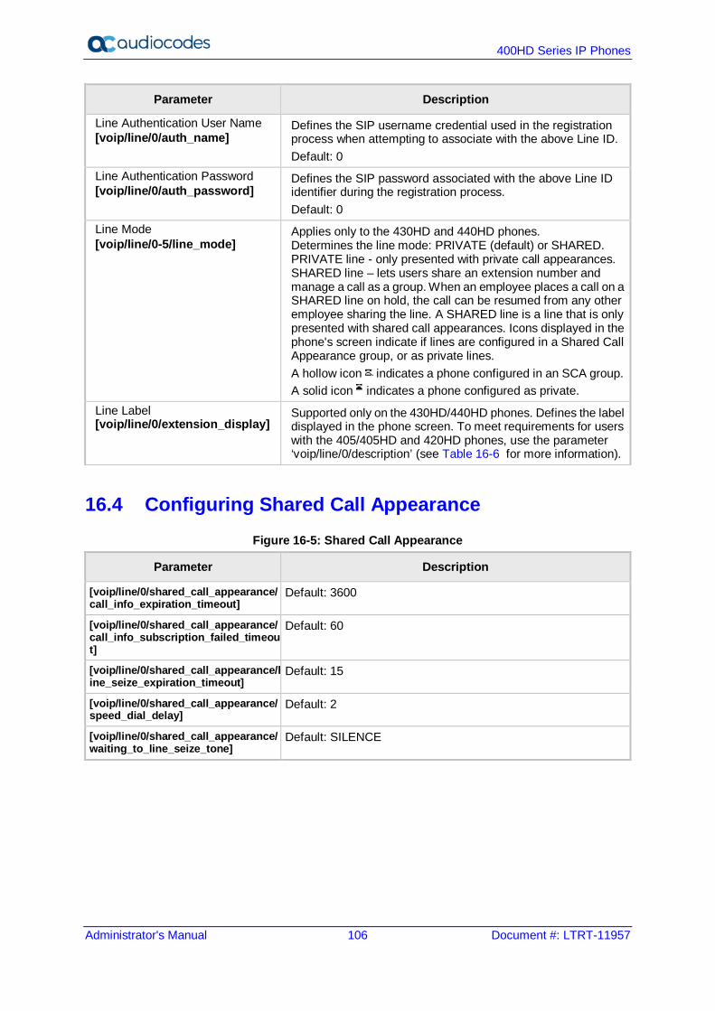
400HD Series IP Phones
Administrator's Manual 106 Document #: LTRT-11957
Parameter Description
Line Authentication User Name [voip/line/0/auth_name]
Defines the SIP username credential used in the registration process when attempting to associate with the above Line ID. Default: 0
Line Authentication Password [voip/line/0/auth_password]
Defines the SIP password associated with the above Line ID identifier during the registration process. Default: 0
Line Mode [voip/line/0-5/line_mode]
Applies only to the 430HD and 440HD phones. Determines the line mode: PRIVATE (default) or SHARED. PRIVATE line - only presented with private call appearances. SHARED line – lets users share an extension number and manage a call as a group. When an employee places a call on a SHARED line on hold, the call can be resumed from any other employee sharing the line. A SHARED line is a line that is only presented with shared call appearances. Icons displayed in the phone's screen indicate if lines are configured in a Shared Call Appearance group, or as private lines. A hollow icon indicates a phone configured in an SCA group. A solid icon indicates a phone configured as private.
Line Label [voip/line/0/extension_display]
Supported only on the 430HD/440HD phones. Defines the label displayed in the phone screen. To meet requirements for users with the 405/405HD and 420HD phones, use the parameter ‘voip/line/0/description’ (see Table 16-6 for more information).
16.4 Configuring Shared Call Appearance Figure 16-5: Shared Call Appearance
Parameter Description
[voip/line/0/shared_call_appearance/call_info_expiration_timeout]
Default: 3600
[voip/line/0/shared_call_appearance/call_info_subscription_failed_timeout]
Default: 60
[voip/line/0/shared_call_appearance/line_seize_expiration_timeout]
Default: 15
[voip/line/0/shared_call_appearance/speed_dial_delay]
Default: 2
[voip/line/0/shared_call_appearance/waiting_to_line_seize_tone]
Default: SILENCE

Administrator's Manual 16. Configuring SIP Settings
Version 2.2.16 107 400HD Series IP Phones
16.5 Configuring SIP Timers SIP Timers can be configured using the Web interface or configuration file.
To configure SIP timer settings using the Web interface: 1. Open the Signaling Protocol page (Configuration tab > Voice Over IP menu >
Signaling Protocols).
Figure 16-6: Signaling Protocols - SIP Timers
2. Configure the SIP Timers parameters using the table below as reference, and then click
Submit.
To configure SIP timer settings using the configuration file:
• Use the table below as reference.
Table 16-7: SIP Timers Parameters
Parameter Description
Retransmission Timer T1 [voip/signalling/sip/sip_t1]
The time interval (in msec) between the first transmission of a SIP message and the first retransmission of the same message (according to RFC 3261). The valid range is 100 to 60000. The default value is 500. Note: The time interval between subsequent retransmissions of the same SIP message starts with SipT1Rtx and is multiplied by two until SipT2Rtx. For example (assuming that SipT1Rtx = 500 and SipT2Rtx = 4000): The first retransmission is sent after 500 msec. The second retransmission is sent after 1000 (2*500)
msec. The third retransmission is sent after 2000 (2*1000)
msec. The fourth retransmission and subsequent
retransmissions until SIPMaxRtx are sent after 4000 (2*2000) msec.
Note also: If dual registration / redundant Genesys server is configured and the configuration file parameter 'voip/signalling/sip/redundant_proxy/dual_reg/t1' is then configured, its value will override 'Retransmission Timer T1'. See also Section A.3.18 and Section A.3.18.1.
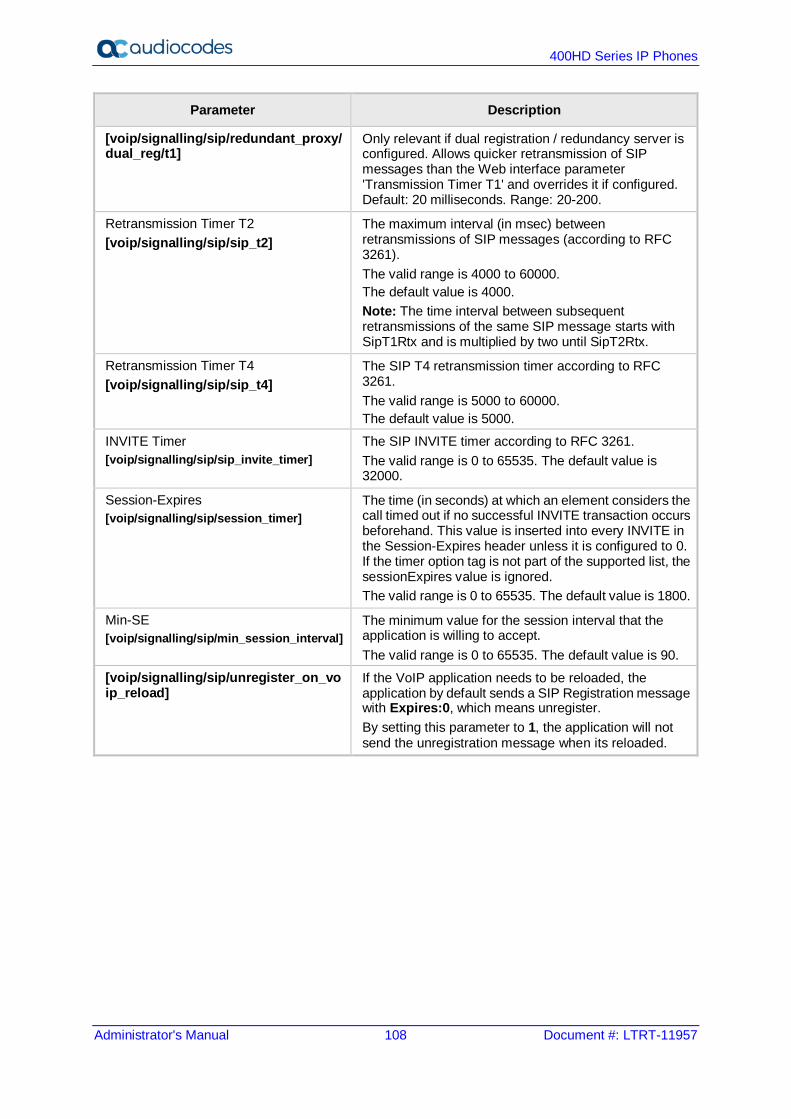
400HD Series IP Phones
Administrator's Manual 108 Document #: LTRT-11957
Parameter Description
[voip/signalling/sip/redundant_proxy/dual_reg/t1]
Only relevant if dual registration / redundancy server is configured. Allows quicker retransmission of SIP messages than the Web interface parameter 'Transmission Timer T1' and overrides it if configured. Default: 20 milliseconds. Range: 20-200.
Retransmission Timer T2 [voip/signalling/sip/sip_t2]
The maximum interval (in msec) between retransmissions of SIP messages (according to RFC 3261). The valid range is 4000 to 60000. The default value is 4000. Note: The time interval between subsequent retransmissions of the same SIP message starts with SipT1Rtx and is multiplied by two until SipT2Rtx.
Retransmission Timer T4 [voip/signalling/sip/sip_t4]
The SIP T4 retransmission timer according to RFC 3261. The valid range is 5000 to 60000. The default value is 5000.
INVITE Timer [voip/signalling/sip/sip_invite_timer]
The SIP INVITE timer according to RFC 3261. The valid range is 0 to 65535. The default value is 32000.
Session-Expires [voip/signalling/sip/session_timer]
The time (in seconds) at which an element considers the call timed out if no successful INVITE transaction occurs beforehand. This value is inserted into every INVITE in the Session-Expires header unless it is configured to 0. If the timer option tag is not part of the supported list, the sessionExpires value is ignored. The valid range is 0 to 65535. The default value is 1800.
Min-SE [voip/signalling/sip/min_session_interval]
The minimum value for the session interval that the application is willing to accept. The valid range is 0 to 65535. The default value is 90.
[voip/signalling/sip/unregister_on_voip_reload]
If the VoIP application needs to be reloaded, the application by default sends a SIP Registration message with Expires:0, which means unregister. By setting this parameter to 1, the application will not send the unregistration message when its reloaded.
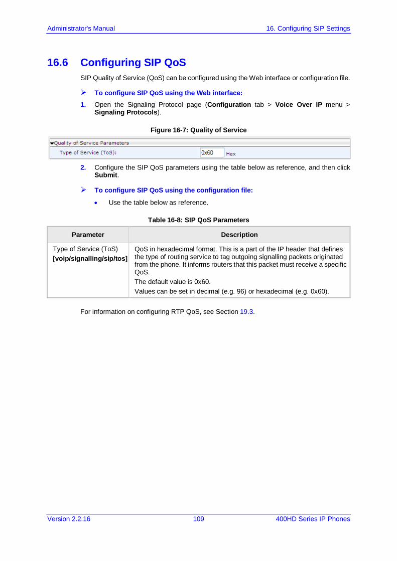
Administrator's Manual 16. Configuring SIP Settings
Version 2.2.16 109 400HD Series IP Phones
16.6 Configuring SIP QoS SIP Quality of Service (QoS) can be configured using the Web interface or configuration file.
To configure SIP QoS using the Web interface: 1. Open the Signaling Protocol page (Configuration tab > Voice Over IP menu >
Signaling Protocols).
Figure 16-7: Quality of Service
2. Configure the SIP QoS parameters using the table below as reference, and then click
Submit.
To configure SIP QoS using the configuration file:
• Use the table below as reference.
Table 16-8: SIP QoS Parameters
Parameter Description
Type of Service (ToS) [voip/signalling/sip/tos]
QoS in hexadecimal format. This is a part of the IP header that defines the type of routing service to tag outgoing signalling packets originated from the phone. It informs routers that this packet must receive a specific QoS. The default value is 0x60. Values can be set in decimal (e.g. 96) or hexadecimal (e.g. 0x60).
For information on configuring RTP QoS, see Section 19.3.

400HD Series IP Phones
Administrator's Manual 110 Document #: LTRT-11957
16.7 Configuring SIP Reject Code Reject Code can be configured using the Web interface or configuration file.
To configure Reject Code using the Web Interface: 1. Open the Services page (Configuration tab > Voice Over IP menu > Services >
General Parameters).
Figure 16-8: General Parameters - Reject Code
2. Configure 'Reject Code' using the table below as reference, and then click Submit.
To configure Reject Code using the configuration file:
• Use the table below as reference.
Table 16-9: Reject Code Parameter
Parameter Description
Reject Code [voip/services/reject_code]
Configures the reject code that the phone sends when the Reject softkey is pressed or while DND is activated. Valid values are: [CODE_603] [CODE_486]
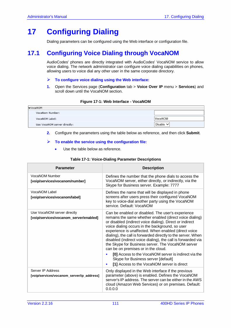
Administrator's Manual 17. Configuring Dialing
Version 2.2.16 111 400HD Series IP Phones
17 Configuring Dialing Dialing parameters can be configured using the Web interface or configuration file.
17.1 Configuring Voice Dialing through VocaNOM AudioCodes' phones are directly integrated with AudioCodes' VocaNOM service to allow voice dialing. The network administrator can configure voice dialing capabilities on phones, allowing users to voice dial any other user in the same corporate directory.
To configure voice dialing using the Web interface: 1. Open the Services page (Configuration tab > Voice Over IP menu > Services) and
scroll down until the VocaNOM section.
Figure 17-1: Web Interface - VocaNOM
2. Configure the parameters using the table below as reference, and then click Submit.
To enable the service using the configuration file:
• Use the table below as reference.
Table 17-1: Voice-Dialing Parameter Descriptions
Parameter Description
VocaNOM Number [voip/services/vocanom/number]
Defines the number that the phone dials to access the VocaNOM server, either directly, or indirectly, via the Skype for Business server. Example: 7777
VocaNOM Label [voip/services/vocanom/label]
Defines the name that will be displayed in phone screens after users press their configured VocaNOM key to voice-dial another party using the VocaNOM service. Default: VocaNOM
Use VocaNOM server directly [voip/services/vocanom_server/enabled]
Can be enabled or disabled. The user's experience remains the same whether enabled (direct voice dialing) or disabled (indirect voice dialing). Direct or indirect voice dialing occurs in the background, so user experience is unaffected. When enabled (direct voice dialing), the call is forwarded directly to the server. When disabled (indirect voice dialing), the call is forwarded via the Skype for Business server. The VocaNOM server can be on premises or in the cloud. [0] Access to the VocaNOM server is indirect via the
Skype for Business server [default] [1] Access to the VocaNOM server is direct
Server IP Address [voip/services/vocanom_server/ip_address]
Only displayed in the Web interface if the previous parameter (above) is enabled. Defines the VocaNOM server's IP address. The server can be either in the AWS cloud (Amazon Web Services) or on premises. Default: 0.0.0.0

400HD Series IP Phones
Administrator's Manual 112 Document #: LTRT-11957
Parameter Description
[voip/services/vocanom_server/port] Defines the port number on the VocaNOM server. Its value must match Transport Mode. 5060 [for UDP, TCP] 5061 [default] [for TLS]
[voip/services/vocanom/transport_mode] Defines the Transport Mode for sending SIP messages. TLS [Default] UDP TCP
17.2 Configuring General Dialing Parameters General dialing parameters can be configured using the Web interface or configuration file.
To configure dialing using the Web interface: 3. Open the Dialing page (Configuration tab > Voice Over IP menu > Dialing).
Figure 17-2: Web Interface Dialing
4. Configure the parameters using the table below as reference, and then click Submit.
To configure dialing using the configuration file:
• Use the table below as reference.
Table 17-2: Dialing Parameters
Parameter Description
Dialing Timeout [voip/dialing/timeout]
The duration (in seconds) of allowed inactivity between dialled digits. When you work with a proxy, the number you have dialled before the dialing process has timed out is sent to the proxy as the user ID to be called. This is useful for calling a remote party without creating a speed dial entry (assuming the remote party is registered with the proxy). Range is 0 to 10. Default = 5.
Interdigit Short Timeout [voip/dialing/interdigit_short_timeout]
Shorter than 'Dialing Timeout' (see above). Default: 3 seconds. Implemented as 0S for the Dial Map. If a user wants to make an international call by dialing 00 and wants to dial the secretary/operator by dialing 0, the user can do both by adding 0S to the Dial Map. For example, if the digit map string= *xx|[2-9]11|0S|[2-9]xxxxxxxxx|1xxx[2-9]xxxxxx, it has 0S in it. When the user dials 0, 0 will match 0S and will therefore start the 'Interdigit Short Timeout' timer. After this timeout, 0 is dialed out. User can dial 00 or 0123 within the 'Interdigit Short Timeout'. After the 'Dialing Timeout', the

Administrator's Manual 17. Configuring Dialing
Version 2.2.16 113 400HD Series IP Phones
Parameter Description
string is dialed out.
Phone Number Length [voip/dialing/phone_number_max_size]
The maximum length of shortcut numbers that you can enter and the maximum number of digits that you can dial Range is 3 to 32. Default = 32.
Enable Dialing Complete Key [voip/dialing/dial_complete_key/enabled]
Enables the feature for defining a key to indicate that dialing has completed. Pressing the Dialing Complete key (defined below) forces the phone to make a call to the dialled digits even if there is no match in the dial plan or digit map. [0] Disable [1] Enable (default) Note: This parameter is available only if the parameter 'voip/dialing/dial_complete_key/enabled' is set to 1.
Dialing Complete Key [voip/dialing/dial_complete_key/key]
Defines the Dialing Complete key. The valid value is a single character. The default value is the pound (#) key.
No Answer Call Timeout [voip/dialing/unanswered_call_timeout]
Timeout before the phone automatically sends a Cancel message. When the phone makes a call and the other side doesn't answer, the phone sends a Cancel after this timeout. Range: 1 to 300. Default = 60.
[voip/dialing/on_hook_dialing] Defines the dialing mode when phone is on hook and no audio device is selected (when user enters digits on idle state). Valid values are: [Disable] = Ignore digits press. To initiate a call, users will have to select audio device by pressing speaker or headset keys or by picking headset. [Open_default_audio_device] = default behavior – start dialing via default audio device (usually speaker) activated. [Off_line_dialing] = don`t activate the default audio device until pressing 'dial' , DTMF tones will not be heard and dialing related features (such as 'dialing timeout' , 'dial complete key' , and more) will be disabled.
[voip/dialing/allow_calling_self_extension] If disabled (default), calling the self-number (user ID) will be blocked. If enabled, the phone will send the invite although it is for its own extension. (In some proxies this is how you access voice mail).

400HD Series IP Phones
Administrator's Manual 114 Document #: LTRT-11957
17.3 Configuring Auto Redial The administrator is responsible for enabling/disabling the auto-redial feature. If enabled and a called party is unavailable because they're busy (for example), the caller's phone's SCREEN prompts Extension Busy. Activate auto redial on busy? If the caller then activates auto-redial by pressing Yes, the busy extension is automatically redialed every n seconds. The administrator is also responsible for configuring this frequency.
To configure auto redial using the Web interface: 1. In the Dialing page, scroll down until the Automatic Redial On Busy section (VoIP >
Dialing > Automatic Redial On Busy).
Figure 17-3: Automatic Redial On Busy
2. Configure the parameters using the table below as reference, and then click Submit.
To configure dialing using the configuration file:
• Use the table below as reference.
Table 17-3: Automatic Redial On Busy Parameters
Parameter Description
Activate [voip/dialing/automatic_redial_on_busy/enabled]
Allows the administrator disable/enable the feature. [0]=Disabled [1]=Enabled Default: 0
Timeout [voip/dialing/automatic_redial_on_busy/retry_timer]
Visible only if the feature is enabled. Range: 3-120. Default: 30. If the feature is activated and the timer lapses, an outgoing call to the busy destination is established. If the feature is activated, a countdown screen is displayed: Dialing <ext> within <x>s (Line <n>) The screen shows the timer, the remote extension and the line number.
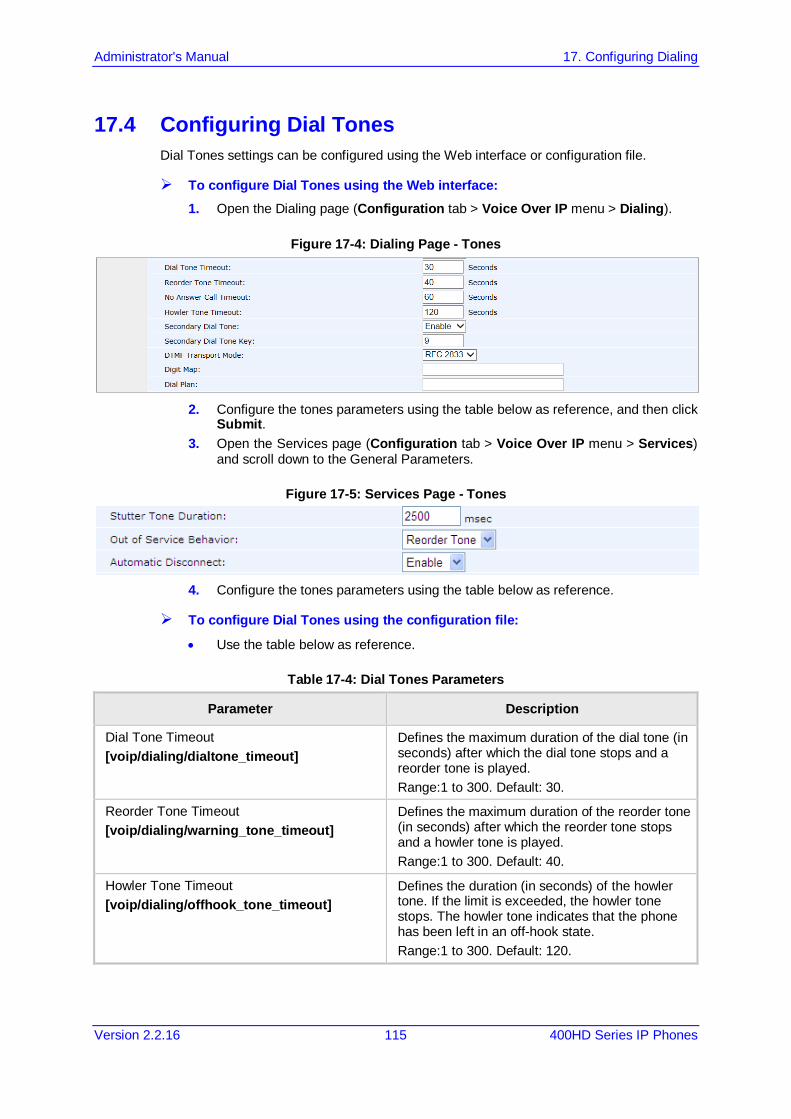
Administrator's Manual 17. Configuring Dialing
Version 2.2.16 115 400HD Series IP Phones
17.4 Configuring Dial Tones Dial Tones settings can be configured using the Web interface or configuration file.
To configure Dial Tones using the Web interface: 1. Open the Dialing page (Configuration tab > Voice Over IP menu > Dialing).
Figure 17-4: Dialing Page - Tones
2. Configure the tones parameters using the table below as reference, and then click
Submit. 3. Open the Services page (Configuration tab > Voice Over IP menu > Services)
and scroll down to the General Parameters.
Figure 17-5: Services Page - Tones
4. Configure the tones parameters using the table below as reference.
To configure Dial Tones using the configuration file:
• Use the table below as reference.
Table 17-4: Dial Tones Parameters
Parameter Description
Dial Tone Timeout [voip/dialing/dialtone_timeout]
Defines the maximum duration of the dial tone (in seconds) after which the dial tone stops and a reorder tone is played. Range:1 to 300. Default: 30.
Reorder Tone Timeout [voip/dialing/warning_tone_timeout]
Defines the maximum duration of the reorder tone (in seconds) after which the reorder tone stops and a howler tone is played. Range:1 to 300. Default: 40.
Howler Tone Timeout [voip/dialing/offhook_tone_timeout]
Defines the duration (in seconds) of the howler tone. If the limit is exceeded, the howler tone stops. The howler tone indicates that the phone has been left in an off-hook state. Range:1 to 300. Default: 120.

400HD Series IP Phones
Administrator's Manual 116 Document #: LTRT-11957
Parameter Description
Secondary Dial Tone [voip/dialing/secondary_dial_tone/enabled]
Enables the secondary dial tone. [0] Disable (default) - Phone doesn't use
secondary dial tone. [1] Enable - Phone plays secondary dial tone if
the secondary dial tone key is pressed (first digit). For example, when pressing 9 to get an external dial tone, a different dial tone (not configurable) is played as the second dial tone.
Secondary Dial Tone Key [voip/dialing/secondary_dial_tone/key_sequence]
Defines the secondary dial tone is played if this is the first key pressed. Range: 0 to 9. Default: 9. Note: This parameter is available only if the parameter 'voip/dialing/secondary_dial_tone/enabled' is set to 1.
Out of Service Behavior [voip/services/out_of_service_behavior]
Determines whether a reorder tone is played instead of a dial tone if you configured a Registrar IP address and the registration failed. [NONE] No Tone [REORDER_TONE] Reorder Tone (default)
Stutter Tone Duration [voip/services/msg_waiting/stutter_tone_duration]
Defines the duration for which a stutter tone is played when you have unheard messages. Range:1000 to 60000. Default: 2500.
Automatic Disconnect [voip/dialing/automatic_disconnect]
Determines whether the phone automatically goes idle (i.e. on-hook) when the last remaining call is disconnected. This is only relevant when the speaker or headset is used. [0] Disable [1] Enable (default)

Administrator's Manual 17. Configuring Dialing
Version 2.2.16 117 400HD Series IP Phones
17.5 Configuring DTMF Dual-Tone Multi-Frequency (DTMF) signaling can be configured using the Web interface or configuration file.
To configure DTMF using the Web interface: 1. Open the Dialing page (Configuration tab > Voice Over IP menu > Dialing).
Figure 17-6: DTMF Transport Mode
2. You can choose one of three available DTMF transport methods:
3. The Web interface allows selecting Inband, RFC 2833, or Via SIP as the DTMF
transport type. 4. Configure the parameter using the table below as reference, and then click Submit.
To configure DTMF using the configuration file:
• Use the table below as reference.
Table 17-5: DTMF Transport Mode
Parameter Description
DTMF Transport Mode [voip/media/out_of_band_dtmf]
DTMF transport mode. [INBAND] Inband [RFC2833] RFC 2833 (default) [VIA_SIP] Via SIP
[voip/media/dtmf_via_sip_force_flag] Must be set to 1 to enable Via SIP as DTMF transport type.
Note:
• The Web interface parameter 'DTMF Transport Mode' and the cfg file parameter 'voip/media/out_of_band_dtmf' are related; changing one changes the other.
• If the cfg file parameter 'voip/media/dtmf_via_sip_force_flag' is enabled, a SIP message is sent in addition to the RTP message. If it is disabled, only one message is sent, according to the selected DTMF transport type.

400HD Series IP Phones
Administrator's Manual 118 Document #: LTRT-11957
17.6 Configuring Digit Maps and Dial Plans Digit maps and Dial plans can be configured using the Web interface or configuration file.
To configure digit map and dial plan using the Web interface: 1. Open the Dialing page (Configuration tab > Voice Over IP menu > Dialing).
Figure 17-7: Digit Map and Dial Plan
2. Configure the parameters using the table below as reference, and then click Submit.
To configure digit map and dial plan using the configuration file:
• Use the table below as reference.
Note: Invalid Tokens will be ignored by the application.
Table 17-6: Digit Map and Dial Plan Parameters
Parameter Description
Digit Map [voip/signalling/sip/digit_map]
Enables the administrator to predefine possible formats (or patterns) for the dialed number. A match to one of the defined patterns terminates the dialed number. The valid value can be up to 256 characters. There are two main formats for the digit map configuration. The formats are distinguished by the separator ';' or '|'. Using '|' separator: The following constructs can be used
in each numbering scheme: Digit: A digit from 0 to 9. DTMF: A digit, or one of the symbols A, B, C, D, #, or
*. Extensions may be defined. Wildcard: The symbol x which matches any digit (0 to
9). * Range: One or more DTMF symbols enclosed
between square brackets ([ and ]). Sub range: Two digits separated by hyphen (-) which
matches any digit between and including the two. The subrange construct can only be used inside a range construct, i.e., between [ and ].
Position: A period (.) which matches an arbitrary number, including zero, of occurrences of the preceding construct.
For example: [2-9]11|0|100|101|011xxx.|9011xxx.|1[2-9]xxxxxxxxx|91[2-9]xxxxxxxxx|9[2-9]xxxxxx|*xx|[8]xxxx|[2-7]xxx This example includes the following rules: [2-9]11: 911 rule: 211, 311, 411, 511, 611, 711, 811,
911 are dialed immediately 0: Local operator rule: After dialing 0 the phone waits
T seconds and then completes the call automatically

Administrator's Manual 17. Configuring Dialing
Version 2.2.16 119 400HD Series IP Phones
Parameter Description
100: Auto-attendant default extension 101: Voicemail default extension 011xxx.: International rule without prefix 9011xxx.: International rule with prefix 1[2-9]xxxxxxxxx: LD rule without prefix 91[2-9]xxxxxxxxx: LD rule with prefix 9[2-9]xxxxxx: Local call with prefix *xx: 2-digit star codes [1-7]xx: A regular 3 digit extension that does not start
with 9 or 8 is dialed immediately [2-7]xx: A regular 3 digit extension that does not start
with 9 or 8 or 1 is dialed immediately [2-7]xxx: A regular 4 digit extension that does not
start with 9 or 8 or 1 is dialed immediately [8]xxx: A 3 digit extension prefixed with an 8 (routes
calls directly to voicemail of extension xxx) [8]xxxx: A 4 digit extension prefixed with an 8 (routes
calls directly to voicemail of extension xxxx) T: Refers to the Dialing Timeout.
Using ';' separator: An 'x' in the pattern indicates any digit. ';' separates between patterns. For example: '10x;05xxxxxxxx;4xxx'. In this example, three patterns are defined. A number that starts with 10 is terminated after the third digit, and so on. If the user dials a number that does not match any pattern, the number is terminated using the timeout or when the user presses the pound ('#') key.
Dial Plan voip/signalling/sip/number_rules
This parameter works in conjunction with the parameter voip/signalling/sip/digit_map and enables translation of specific patterns to specific SIP destination addresses. An 'x' represents any dialed digit. Each backslash at the right side of the '=' represents one of the dialed digits. Rules are separated by the character ';'. The valid value can be up to 256 characters. For example: '4xxx=Line_\\\@10.1.2.3' This rule issues a call to 10.1.2.3 with the SIP ID of Line_ followed by the last three digits of the dialed number.
400HD Series IP Phones
Administrator's Manual 120 Document #: LTRT-11957
17.7 Configuring Headset LED to Stay On IT administrators can configure the headset LED to stay on when the phone is on standby and when it is in conversation mode.
Note: Headset must be configured as the default audio device for the feature to function (see Section 17.8).
To configure the headset LED to stay on:
• Use the table below as reference.
Table 17-7: Headset LED Parameter
Parameter Description
[voip/highlight_audio_device] Allows the headset LED to stay on when the phone is on standby and when it is in conversation mode. Functions only when headset is configured as the default audio device. Configure either: [NONE] (Default) Headset LED illuminates only when the
phone is in conversation mode. [HEADSET] = Headset LED illuminates when the phone
is on standby and when it is in conversation mode
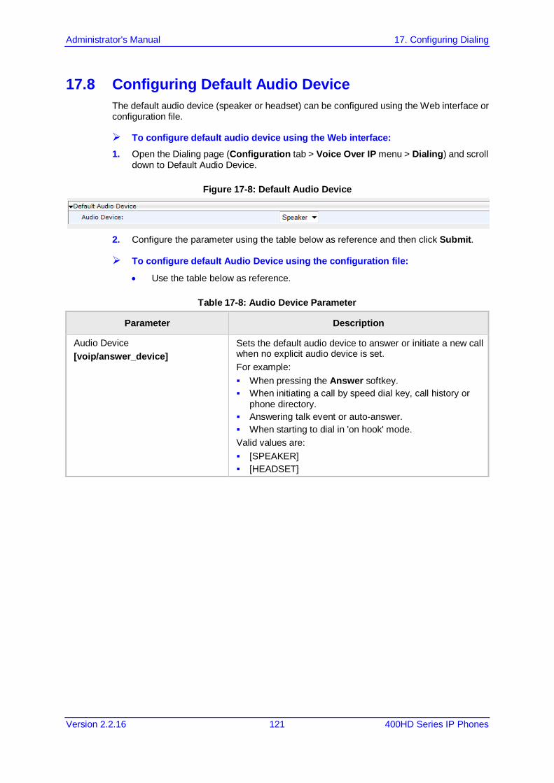
Administrator's Manual 17. Configuring Dialing
Version 2.2.16 121 400HD Series IP Phones
17.8 Configuring Default Audio Device The default audio device (speaker or headset) can be configured using the Web interface or configuration file.
To configure default audio device using the Web interface: 1. Open the Dialing page (Configuration tab > Voice Over IP menu > Dialing) and scroll
down to Default Audio Device.
Figure 17-8: Default Audio Device
2. Configure the parameter using the table below as reference and then click Submit.
To configure default Audio Device using the configuration file:
• Use the table below as reference.
Table 17-8: Audio Device Parameter
Parameter Description
Audio Device [voip/answer_device]
Sets the default audio device to answer or initiate a new call when no explicit audio device is set. For example: When pressing the Answer softkey. When initiating a call by speed dial key, call history or
phone directory. Answering talk event or auto-answer. When starting to dial in 'on hook' mode. Valid values are: [SPEAKER] [HEADSET]

400HD Series IP Phones
Administrator's Manual 122 Document #: LTRT-11957
This page is intentionally left blank.
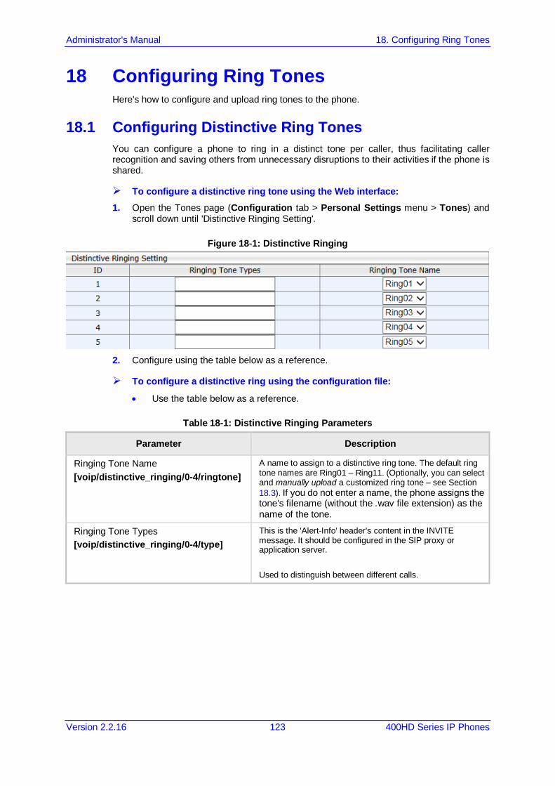
Administrator's Manual 18. Configuring Ring Tones
Version 2.2.16 123 400HD Series IP Phones
18 Configuring Ring Tones Here's how to configure and upload ring tones to the phone.
18.1 Configuring Distinctive Ring Tones You can configure a phone to ring in a distinct tone per caller, thus facilitating caller recognition and saving others from unnecessary disruptions to their activities if the phone is shared.
To configure a distinctive ring tone using the Web interface: 1. Open the Tones page (Configuration tab > Personal Settings menu > Tones) and
scroll down until 'Distinctive Ringing Setting'.
Figure 18-1: Distinctive Ringing
2. Configure using the table below as a reference.
To configure a distinctive ring using the configuration file:
• Use the table below as a reference.
Table 18-1: Distinctive Ringing Parameters
Parameter Description
Ringing Tone Name [voip/distinctive_ringing/0-4/ringtone]
A name to assign to a distinctive ring tone. The default ring tone names are Ring01 – Ring11. (Optionally, you can select and manually upload a customized ring tone – see Section 18.3). If you do not enter a name, the phone assigns the tone's filename (without the .wav file extension) as the name of the tone.
Ringing Tone Types [voip/distinctive_ringing/0-4/type]
This is the 'Alert-Info' header's content in the INVITE message. It should be configured in the SIP proxy or application server. Used to distinguish between different calls.
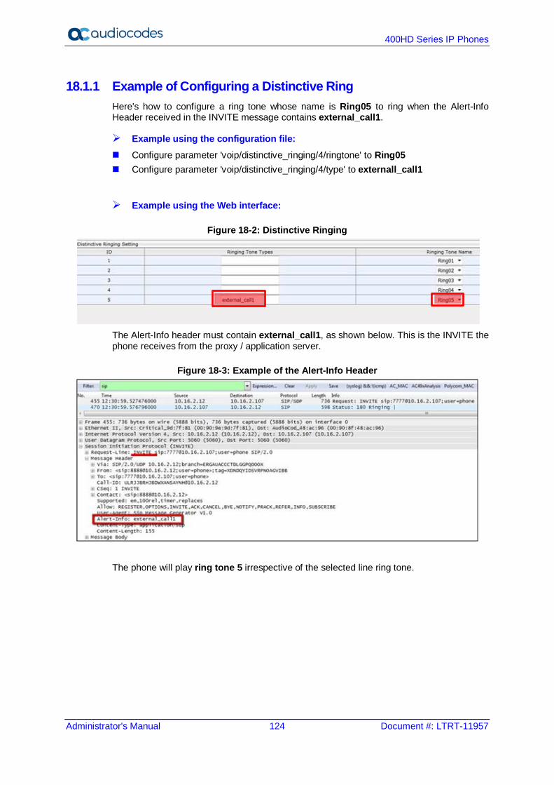
400HD Series IP Phones
Administrator's Manual 124 Document #: LTRT-11957
18.1.1 Example of Configuring a Distinctive Ring Here's how to configure a ring tone whose name is Ring05 to ring when the Alert-Info Header received in the INVITE message contains external_call1.
Example using the configuration file: Configure parameter 'voip/distinctive_ringing/4/ringtone' to Ring05 Configure parameter 'voip/distinctive_ringing/4/type' to externall_call1
Example using the Web interface:
Figure 18-2: Distinctive Ringing
The Alert-Info header must contain external_call1, as shown below. This is the INVITE the phone receives from the proxy / application server.
Figure 18-3: Example of the Alert-Info Header
The phone will play ring tone 5 irrespective of the selected line ring tone.
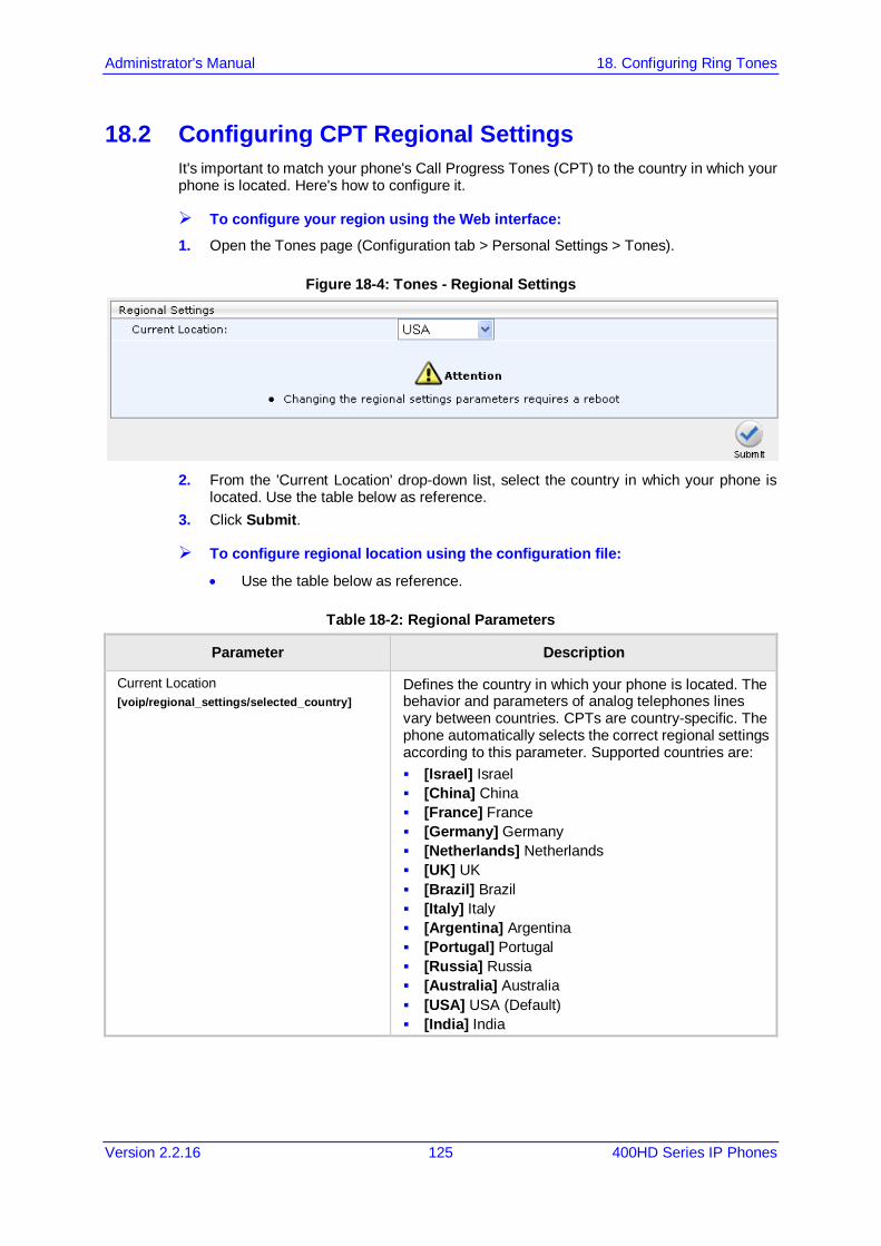
Administrator's Manual 18. Configuring Ring Tones
Version 2.2.16 125 400HD Series IP Phones
18.2 Configuring CPT Regional Settings It's important to match your phone's Call Progress Tones (CPT) to the country in which your phone is located. Here's how to configure it.
To configure your region using the Web interface: 1. Open the Tones page (Configuration tab > Personal Settings > Tones).
Figure 18-4: Tones - Regional Settings
2. From the 'Current Location' drop-down list, select the country in which your phone is
located. Use the table below as reference. 3. Click Submit.
To configure regional location using the configuration file:
• Use the table below as reference.
Table 18-2: Regional Parameters
Parameter Description
Current Location [voip/regional_settings/selected_country]
Defines the country in which your phone is located. The behavior and parameters of analog telephones lines vary between countries. CPTs are country-specific. The phone automatically selects the correct regional settings according to this parameter. Supported countries are: [Israel] Israel [China] China [France] France [Germany] Germany [Netherlands] Netherlands [UK] UK [Brazil] Brazil [Italy] Italy [Argentina] Argentina [Portugal] Portugal [Russia] Russia [Australia] Australia [USA] USA (Default) [India] India

400HD Series IP Phones
Administrator's Manual 126 Document #: LTRT-11957
Parameter Description
[voip/regional_settings/use_config_file_values] Enables the user-defined CPT. When this parameter is enabled, the 'selected_country' parameter is not relevant and the CPT values below can be determined by the user. [0] - Disable (default) [1] - Enable
Call Progress Tones (CPT) Note: Up to 10 CPTs can be configured (voip/regional_settings/call_progress_tones/0…9).
[voip/regional_settings/call_progress_tones/%d/enabled]
Enables the specific CPT. [0] - Disable [1] - Enable
[voip/regional_settings/call_progress_tones/%d/name]
Defines the name of the CPT.
[voip/regional_settings/call_progress_tones/%d/cadence]
Defines the cadence type of the tone. [0] - Continuous signal [1] - Cadence signal [2] - Burst signal
[voip/regional_settings/call_progress_tones/%d/frequency_a]
Defines the low frequency (in Hz) of the tone. Range:300 - 1980 Hz, in steps of 1 Hz. Unused frequencies must be set to zero.
[voip/regional_settings/call_progress_tones/%d/frequency_b]
Defines the high frequency (in Hz) of the tone. Range:300 - 3000 Hz, in steps of 1 Hz. Unused frequencies must be set to zero.
[voip/regional_settings/call_progress_tones/%d/frequency_a_level]
Output level of the low frequency tone (in -dBm) in Call Progress generation. Range: 0 - 63, where 63 is mute.
[voip/regional_settings/call_progress_tones/%d/frequency_b_level]
Output level of the low frequency tone (in -dBm) in Call Progress generation.Range:0 - 63, where 63 is mute.
[voip/regional_settings/call_progress_tones/2/name]
Default: busy_tone The calling party hears a busy tone if the called party's line is busy. The busy tone complies with international telcom standards in traditional non-VOIP telephony systems.
[voip/regional_settings/call_progress_tones/%d/tone_on_0]
tone_on_0 to tone_on_3. If the signal is Cadence or Burst, then this value represents the on duration. If a Continuous tone, then this value represents the minimum detection time. In units of 10 msec.Range:0 - 10000.
[voip/regional_settings/call_progress_tones/%d/tone_off_0]
tone_off_0 to tone_on_3. If the signal is Cadence, then this value represents the off duration, in units of 10 msec. If not used, then set it to zero. If the signal is Burst, only tone_off 0 is relevant. It represents the off time that is required from the end of the signal to the detection time.Range:0 - 10000.
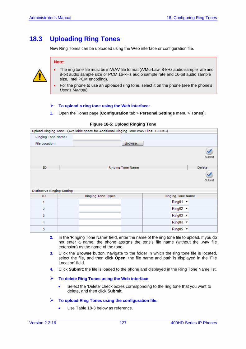
Administrator's Manual 18. Configuring Ring Tones
Version 2.2.16 127 400HD Series IP Phones
18.3 Uploading Ring Tones New Ring Tones can be uploaded using the Web interface or configuration file.
Note:
• The ring tone file must be in WAV file format (A/Mu-Law, 8-kHz audio sample rate and 8-bit audio sample size or PCM 16-kHz audio sample rate and 16-bit audio sample size, Intel PCM encoding).
• For the phone to use an uploaded ring tone, select it on the phone (see the phone's User's Manual).
To upload a ring tone using the Web interface: 1. Open the Tones page (Configuration tab > Personal Settings menu > Tones).
Figure 18-5: Upload Ringing Tone
2. In the 'Ringing Tone Name' field, enter the name of the ring tone file to upload. If you do
not enter a name, the phone assigns the tone's file name (without the .wav file extension) as the name of the tone.
3. Click the Browse button, navigate to the folder in which the ring tone file is located, select the file, and then click Open; the file name and path is displayed in the 'File Location' field.
4. Click Submit; the file is loaded to the phone and displayed in the Ring Tone Name list.
To delete Ring Tones using the Web interface:
• Select the 'Delete' check boxes corresponding to the ring tone that you want to delete, and then click Submit.
To upload Ring Tones using the configuration file:
• Use Table 18-3 below as reference.
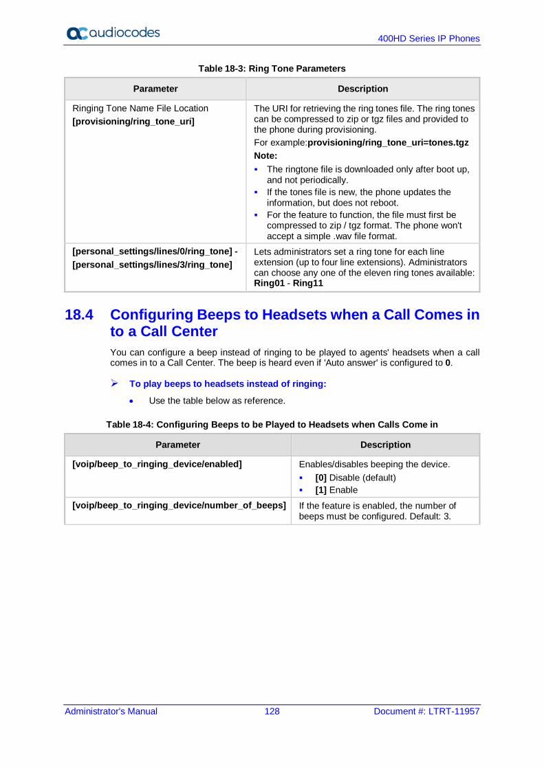
400HD Series IP Phones
Administrator's Manual 128 Document #: LTRT-11957
Table 18-3: Ring Tone Parameters
Parameter Description
Ringing Tone Name File Location [provisioning/ring_tone_uri]
The URI for retrieving the ring tones file. The ring tones can be compressed to zip or tgz files and provided to the phone during provisioning. For example:provisioning/ring_tone_uri=tones.tgz Note: The ringtone file is downloaded only after boot up,
and not periodically. If the tones file is new, the phone updates the
information, but does not reboot. For the feature to function, the file must first be
compressed to zip / tgz format. The phone won't accept a simple .wav file format.
[personal_settings/lines/0/ring_tone] - [personal_settings/lines/3/ring_tone]
Lets administrators set a ring tone for each line extension (up to four line extensions). Administrators can choose any one of the eleven ring tones available: Ring01 - Ring11
18.4 Configuring Beeps to Headsets when a Call Comes in to a Call Center You can configure a beep instead of ringing to be played to agents' headsets when a call comes in to a Call Center. The beep is heard even if 'Auto answer' is configured to 0.
To play beeps to headsets instead of ringing:
• Use the table below as reference.
Table 18-4: Configuring Beeps to be Played to Headsets when Calls Come in
Parameter Description
[voip/beep_to_ringing_device/enabled] Enables/disables beeping the device. [0] Disable (default) [1] Enable
[voip/beep_to_ringing_device/number_of_beeps] If the feature is enabled, the number of beeps must be configured. Default: 3.

Administrator's Manual 18. Configuring Ring Tones
Version 2.2.16 129 400HD Series IP Phones
18.5 Configuring the Phone to play Fast Busy Tone if Automatically Disconnected on Remote Side You can configure the phone to play a fast busy tone if it is automatically disconnected on the remote side. You can also configure for how long this fast busy tone is played. When the phone plays the tone, it also displays a 'Disconnected' message for the same length of time.
To configure this feature:
• Use the table below as reference.
Table 18-5: Configuring the Phone to Play a Fast Busy Tone when Automatically Disconnected on Remote Side
Parameter Description
[enable_remote_disconnect_warningTone] Allows you to enable or disable playing a fast busy tone if the phone is automatically disconnected on the remote side. [0] (default) If the phone accepts an
incoming call and the remote side automatically ends it (disconnects), the phone does not play any tone and no message is displayed.
[1] If the phone accepts an incoming call and the remote side automatically ends (disconnects) it, the phone plays a fast busy tone and displays a Disconnected message (see the parameter description below).
[voip/dialing/automatic_disconnect_delay_timer] Defines for how long the fast busy tone is played and for how long the 'Disconnected' message is displayed if the warningTone parameter above is enabled and the phone is automatically disconnected on the remote side. Default: 3000 ms.

400HD Series IP Phones
Administrator's Manual 130 Document #: LTRT-11957
This page is intentionally left blank.
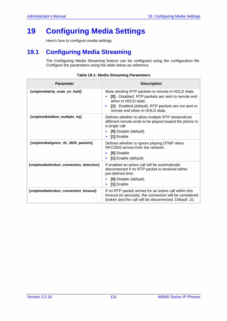
Administrator's Manual 19. Configuring Media Settings
Version 2.2.16 131 400HD Series IP Phones
19 Configuring Media Settings Here's how to configure media settings.
19.1 Configuring Media Streaming The Configuring Media Streaming feature can be configured using the configuration file. Configure the parameters using the table below as reference.
Table 19-1: Media Streaming Parameters
Parameter Description
[voip/media/rtp_mute_on_hold] Mute sending RTP packets to remote in HOLD state. [0] - Disabled. RTP packets are sent to remote end
when in HOLD state. [1] - Enabled (default). RTP packets are not sent to
remote end when in HOLD state. [voip/media/allow_multiple_rtp] Defines whether to allow multiple RTP streamsfrom
different remote ends to be played toward the phone in a single call. [0] Disable (default) [1] Enable
[voip/media/ignore_rfc_2833_packets] Defines whether to ignore playing DTMF when RFC2833 arrives from the network. [0] Disable [1] Enable (default)
[voip/media/broken_connection_detection] If enabled an active call will be automatically disconnected if no RTP packet is received within pre-defined time. [0] Disable (default) [1] Enable
[voip/media/broken_connection_timeout] If no RTP packet arrives for an active call within this timeout (in seconds), the connection will be considered broken and the call will be disconnected. Default: 10.
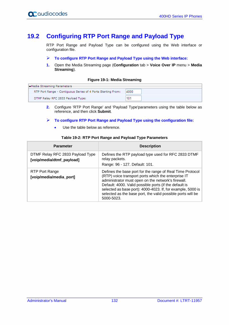
400HD Series IP Phones
Administrator's Manual 132 Document #: LTRT-11957
19.2 Configuring RTP Port Range and Payload Type RTP Port Range and Payload Type can be configured using the Web interface or configuration file.
To configure RTP Port Range and Payload Type using the Web interface: 1. Open the Media Streaming page (Configuration tab > Voice Over IP menu > Media
Streaming).
Figure 19-1: Media Streaming
2. Configure 'RTP Port Range' and 'Payload Type'parameters using the table below as
reference, and then click Submit.
To configure RTP Port Range and Payload Type using the configuration file:
• Use the table below as reference.
Table 19-2: RTP Port Range and Payload Type Parameters
Parameter Description
DTMF Relay RFC 2833 Payload Type [voip/media/dtmf_payload]
Defines the RTP payload type used for RFC 2833 DTMF relay packets. Range: 96 - 127. Default: 101.
RTP Port Range [voip/media/media_port]
Defines the base port for the range of Real Time Protocol (RTP) voice transport ports which the enterprise IT administrator must open on the network's firewall. Default: 4000. Valid possible ports (if the default is selected as base port): 4000-4023. If, for example, 5000 is selected as the base port, the valid possible ports will be 5000-5023.

Administrator's Manual 19. Configuring Media Settings
Version 2.2.16 133 400HD Series IP Phones
19.3 Configuring RTP QoS RTP QoS can be configured using the Web interface or configuration file.
To configure RTP QoS using the Web interface: 1. Open the Media Streaming page (Configuration tab > Voice Over IP menu > Media
Streaming).
Figure 19-2: Quality of Service
2. Configure the QoS parameter using the table below as reference, and then click
Submit.
To configure RTP QoS using the configuration file:
• Use the table below as reference.
Table 19-3: RTP QoS Parameter
Parameter Description
Type of Service (ToS) [voip/media/media_tos]
QoS in hexadecimal format. This is a part of the IP header that defines the type of routing service to tag outgoing voice packets originated from the phone. It informs routers that this packet must receive a specific QoS. The default value is 0xb8. Values can be set in decimal (e.g., 184) or hexadecimal (e.g., 0xb8). Default: 184.
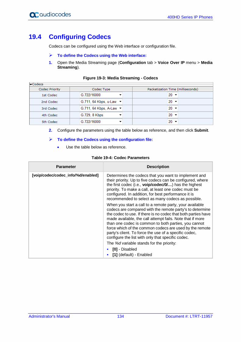
400HD Series IP Phones
Administrator's Manual 134 Document #: LTRT-11957
19.4 Configuring Codecs Codecs can be configured using the Web interface or configuration file.
To define the Codecs using the Web interface: 1. Open the Media Streaming page (Configuration tab > Voice Over IP menu > Media
Streaming).
Figure 19-3: Media Streaming - Codecs
2. Configure the parameters using the table below as reference, and then click Submit.
To define the Codecs using the configuration file:
• Use the table below as reference.
Table 19-4: Codec Parameters
Parameter Description
[voip/codec/codec_info/%d/enabled] Determines the codecs that you want to implement and their priority. Up to five codecs can be configured, where the first codec (i.e., voip/codec/0/…) has the highest priority. To make a call, at least one codec must be configured. In addition, for best performance it is recommended to select as many codecs as possible. When you start a call to a remote party, your available codecs are compared with the remote party's to determine the codec to use. If there is no codec that both parties have made available, the call attempt fails. Note that if more than one codec is common to both parties, you cannot force which of the common codecs are used by the remote party's client. To force the use of a specific codec, configure the list with only that specific codec. The %d variable stands for the priority: [0] - Disabled [1] (default) - Enabled
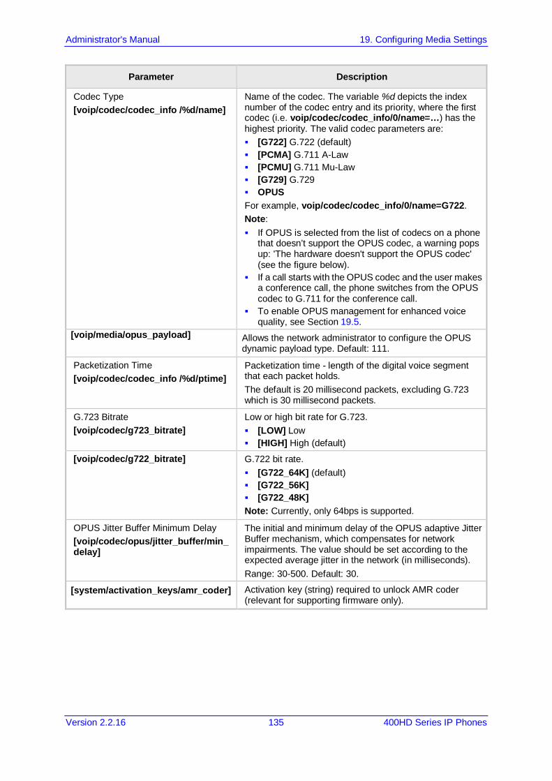
Administrator's Manual 19. Configuring Media Settings
Version 2.2.16 135 400HD Series IP Phones
Parameter Description
Codec Type [voip/codec/codec_info /%d/name]
Name of the codec. The variable %d depicts the index number of the codec entry and its priority, where the first codec (i.e. voip/codec/codec_info/0/name=…) has the highest priority. The valid codec parameters are: [G722] G.722 (default) [PCMA] G.711 A-Law [PCMU] G.711 Mu-Law [G729] G.729 OPUS For example, voip/codec/codec_info/0/name=G722. Note: If OPUS is selected from the list of codecs on a phone
that doesn’t support the OPUS codec, a warning pops up: 'The hardware doesn't support the OPUS codec' (see the figure below).
If a call starts with the OPUS codec and the user makes a conference call, the phone switches from the OPUS codec to G.711 for the conference call.
To enable OPUS management for enhanced voice quality, see Section 19.5.
[voip/media/opus_payload] Allows the network administrator to configure the OPUS dynamic payload type. Default: 111.
Packetization Time [voip/codec/codec_info /%d/ptime]
Packetization time - length of the digital voice segment that each packet holds. The default is 20 millisecond packets, excluding G.723 which is 30 millisecond packets.
G.723 Bitrate [voip/codec/g723_bitrate]
Low or high bit rate for G.723. [LOW] Low [HIGH] High (default)
[voip/codec/g722_bitrate] G.722 bit rate. [G722_64K] (default) [G722_56K] [G722_48K] Note: Currently, only 64bps is supported.
OPUS Jitter Buffer Minimum Delay [voip/codec/opus/jitter_buffer/min_delay]
The initial and minimum delay of the OPUS adaptive Jitter Buffer mechanism, which compensates for network impairments. The value should be set according to the expected average jitter in the network (in milliseconds). Range: 30-500. Default: 30.
[system/activation_keys/amr_coder] Activation key (string) required to unlock AMR coder (relevant for supporting firmware only).
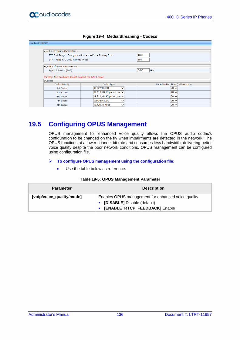
400HD Series IP Phones
Administrator's Manual 136 Document #: LTRT-11957
Figure 19-4: Media Streaming - Codecs
19.5 Configuring OPUS Management OPUS management for enhanced voice quality allows the OPUS audio codec's configuration to be changed on the fly when impairments are detected in the network. The OPUS functions at a lower channel bit rate and consumes less bandwidth, delivering better voice quality despite the poor network conditions. OPUS management can be configured using configuration file.
To configure OPUS management using the configuration file:
• Use the table below as reference.
Table 19-5: OPUS Management Parameter
Parameter Description
[voip/voice_quality/mode] Enables OPUS management for enhanced voice quality. [DISABLE] Disable (default) [ENABLE_RTCP_FEEDBACK] Enable
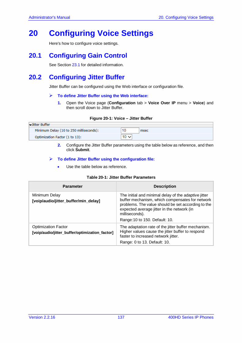
Administrator's Manual 20. Configuring Voice Settings
Version 2.2.16 137 400HD Series IP Phones
20 Configuring Voice Settings Here's how to configure voice settings.
20.1 Configuring Gain Control See Section 23.1 for detailed information.
20.2 Configuring Jitter Buffer Jitter Buffer can be configured using the Web interface or configuration file.
To define Jitter Buffer using the Web interface: 1. Open the Voice page (Configuration tab > Voice Over IP menu > Voice) and
then scroll down to Jitter Buffer.
Figure 20-1: Voice – Jitter Buffer
2. Configure the Jitter Buffer parameters using the table below as reference, and then
click Submit.
To define Jitter Buffer using the configuration file:
• Use the table below as reference.
Table 20-1: Jitter Buffer Parameters
Parameter Description
Minimum Delay [voip/audio/jitter_buffer/min_delay]
The initial and minimal delay of the adaptive jitter buffer mechanism, which compensates for network problems. The value should be set according to the expected average jitter in the network (in milliseconds). Range:10 to 150. Default: 10.
Optimization Factor [voip/audio/jitter_buffer/optimization_factor]
The adaptation rate of the jitter buffer mechanism. Higher values cause the jitter buffer to respond faster to increased network jitter. Range: 0 to 13. Default: 10.
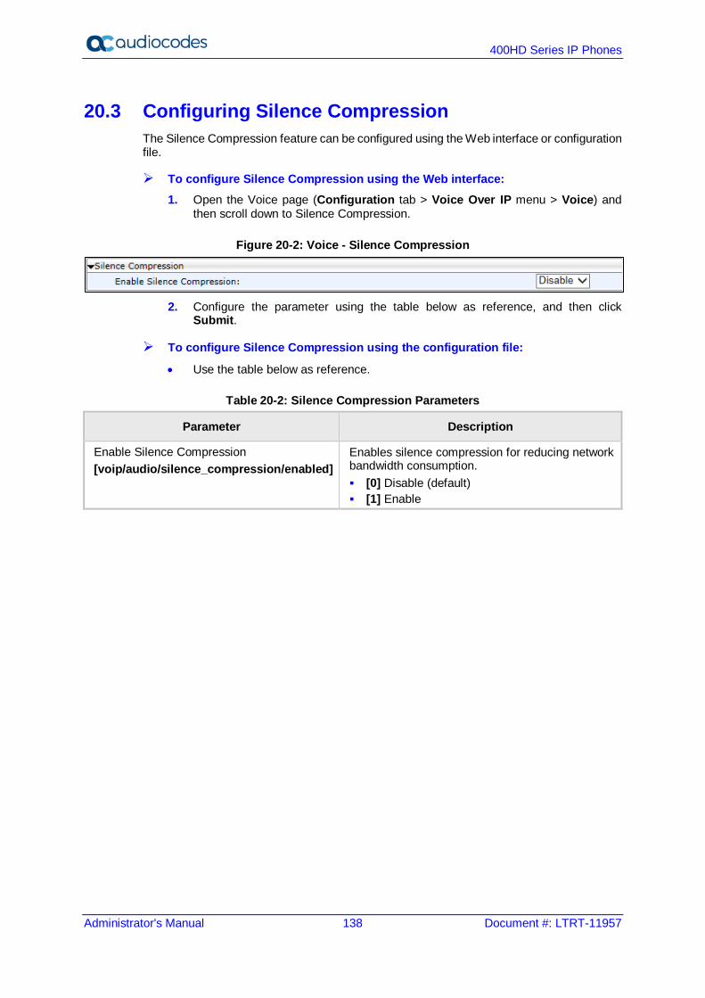
400HD Series IP Phones
Administrator's Manual 138 Document #: LTRT-11957
20.3 Configuring Silence Compression The Silence Compression feature can be configured using the Web interface or configuration file.
To configure Silence Compression using the Web interface: 1. Open the Voice page (Configuration tab > Voice Over IP menu > Voice) and
then scroll down to Silence Compression.
Figure 20-2: Voice - Silence Compression
2. Configure the parameter using the table below as reference, and then click
Submit.
To configure Silence Compression using the configuration file:
• Use the table below as reference.
Table 20-2: Silence Compression Parameters
Parameter Description
Enable Silence Compression [voip/audio/silence_compression/enabled]
Enables silence compression for reducing network bandwidth consumption. [0] Disable (default) [1] Enable
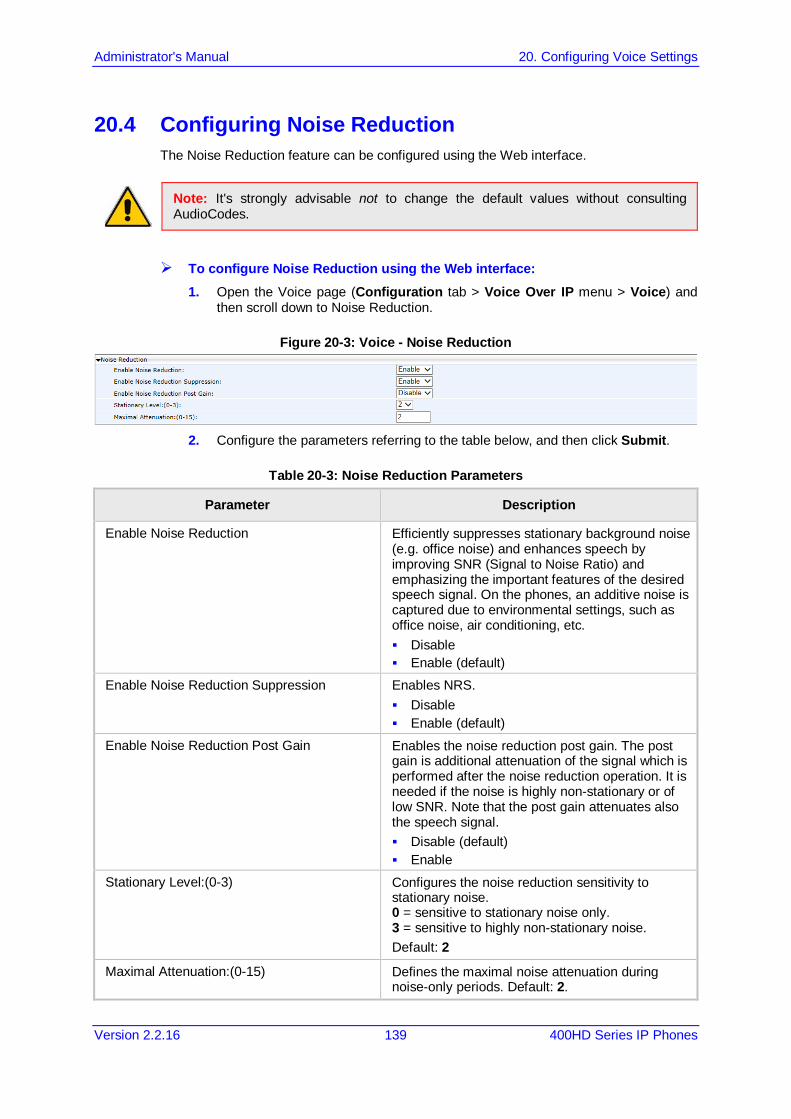
Administrator's Manual 20. Configuring Voice Settings
Version 2.2.16 139 400HD Series IP Phones
20.4 Configuring Noise Reduction The Noise Reduction feature can be configured using the Web interface.
Note: It's strongly advisable not to change the default values without consulting AudioCodes.
To configure Noise Reduction using the Web interface: 1. Open the Voice page (Configuration tab > Voice Over IP menu > Voice) and
then scroll down to Noise Reduction.
Figure 20-3: Voice - Noise Reduction
2. Configure the parameters referring to the table below, and then click Submit.
Table 20-3: Noise Reduction Parameters
Parameter Description
Enable Noise Reduction Efficiently suppresses stationary background noise (e.g. office noise) and enhances speech by improving SNR (Signal to Noise Ratio) and emphasizing the important features of the desired speech signal. On the phones, an additive noise is captured due to environmental settings, such as office noise, air conditioning, etc. Disable Enable (default)
Enable Noise Reduction Suppression Enables NRS. Disable Enable (default)
Enable Noise Reduction Post Gain Enables the noise reduction post gain. The post gain is additional attenuation of the signal which is performed after the noise reduction operation. It is needed if the noise is highly non-stationary or of low SNR. Note that the post gain attenuates also the speech signal. Disable (default) Enable
Stationary Level:(0-3) Configures the noise reduction sensitivity to stationary noise. 0 = sensitive to stationary noise only. 3 = sensitive to highly non-stationary noise. Default: 2
Maximal Attenuation:(0-15) Defines the maximal noise attenuation during noise-only periods. Default: 2.

400HD Series IP Phones
Administrator's Manual 140 Document #: LTRT-11957
20.5 Configuring Echo Cancellation
Note:
• It is strongly advisable to leave the echo cancellation parameters at their defaults and not to configure different values.
• Contact your AudioCodes representative if you encounter an echo cancellation related issue.
You can view the following echo cancellation related parameters in the configuration file (Management tab > Manual Update > Configuration File). voip/audio/echo_cancellation/enabled voip/audio/echo_cancellation/extended_nlp/enabled voip/audio/echo_cancellation/handset/HPF_mode voip/audio/echo_cancellation/handsfree/HPF_mode voip/audio/echo_cancellation/headset/HPF_mode voip/audio/echo_cancellation/nlp/max_delay voip/audio/echo_cancellation/nlp/mode

Administrator's Manual 21. Configuring Extension Lines
Version 2.2.16 141 400HD Series IP Phones
21 Configuring Extension Lines 21.1 On the Phone
Before you can make a call, you must configure an extension line (SIP account). Here's how to configure an extension line on the phone.
Note:
• 440HD / 430HD phone screens are shown here. • 420HD / 405 / 405HD phone screens are virtually identical.
To configure an extension line on the phone: 1. Open the SIP Accounts screen (MENU key > Administration > SIP Accounts).
2. To add a new line extension (SIP account), press the Add softkey (or skip to Step 3 to
define an existing line extension (SIP account).
3. Navigate to the added line and then press the Select softkey; the SIP Details screen
appears.
4. Choose the required SIP parameter, and then press the Select softkey to define it:
• Line Mode (applies only to the 440HD/ 430HD phones) • User ID • Display Name • Authentication Name • Authentication Password • SIP Proxy Address
5. After each parameter setting, press the Save softkey to save the setting. 6. After completing configuring SIP account settings, press the Back softkey until you're
prompted that the phone is rebooting. The screen indicates a warning message: 'Phone is rebooting to apply new settings'.
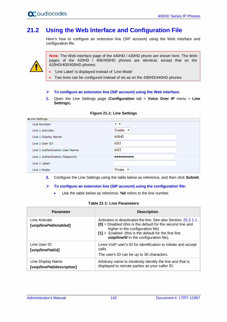
400HD Series IP Phones
Administrator's Manual 142 Document #: LTRT-11957
21.2 Using the Web Interface and Configuration File Here's how to configure an extension line (SIP account) using the Web interface and configuration file.
Note: The Web interface page of the 440HD / 430HD phone are shown here. The Web pages of the 420HD / 405/405HD phones are identical, except that on the 420HD/405/405HD phones:
• 'Line Label' is displayed instead of 'Line Mode' • Two lines can be configured instead of six as on the 430HD/440HD phones
To configure an extension line (SIP account) using the Web interface: 1. Open the Line Settings page (Configuration tab > Voice Over IP menu > Line
Settings).
Figure 21-1: Line Settings
2. Configure the Line Settings using the table below as reference, and then click Submit.
To configure an extension line (SIP account) using the configuration file: • Use the table below as reference. %d refers to the line number.
Table 21-1: Line Parameters
Parameter Description
Line Activate [voip/line/%d/enabled]
Activates or deactivates the line. See also Section. 25.2.1.1. [0] = Disabled (this is the default for the second line and higher in the configuration file) [1] = Enabled (this is the default for the first line voip/line/0/ in the configuration file).
Line User ID [voip/line/%d/id]
Lines VoIP user's ID for identification to initiate and accept calls. The user's ID can be up to 30 characters.
Line Display Name [voip/line/%d/description]
Arbitrary name to intuitively identify the line and that is displayed to remote parties as your caller ID.
Administrator's Manual 21. Configuring Extension Lines
Version 2.2.16 143 400HD Series IP Phones
Parameter Description
Line Authentication User Name [voip/line/%d/auth_name]
User name provided to you from the VoIP service provider. This is used when sending a response to Unauthorized or Proxy Authentication Requested (401/407). The authentication name can be up to 35 characters.
Line Authentication Password [voip/line/%d/auth_password]
Password provided to you from the VoIP Service Provider. This is used when sending a response to Unauthorized or Proxy Authentication Requested (401/407). The authentication password can be up to 35 characters.
Line Label [voip/line/%d/extension_display]
[Only applies to the 420HD and 405/405HD phones] Set the string that will be displayed in the phone screen for local extension. If not set, the local extension displayed will be the user ID (self-number).
Line Mode [voip/line/%d/line_mode]
[Only applies to 430HD/440HD phones] Determines the line mode: PRIVATE (default) or SHARED. SHARED allows enterprise employees to share an extension number and manage a call as a group. When an employee places a call on a SHARED line on hold, the call can be resumed from any other employee sharing the line.
Note: You can activate DnD per phone line (see Section 22.8).

400HD Series IP Phones
Administrator's Manual 144 Document #: LTRT-11957
This page is intentionally left blank.
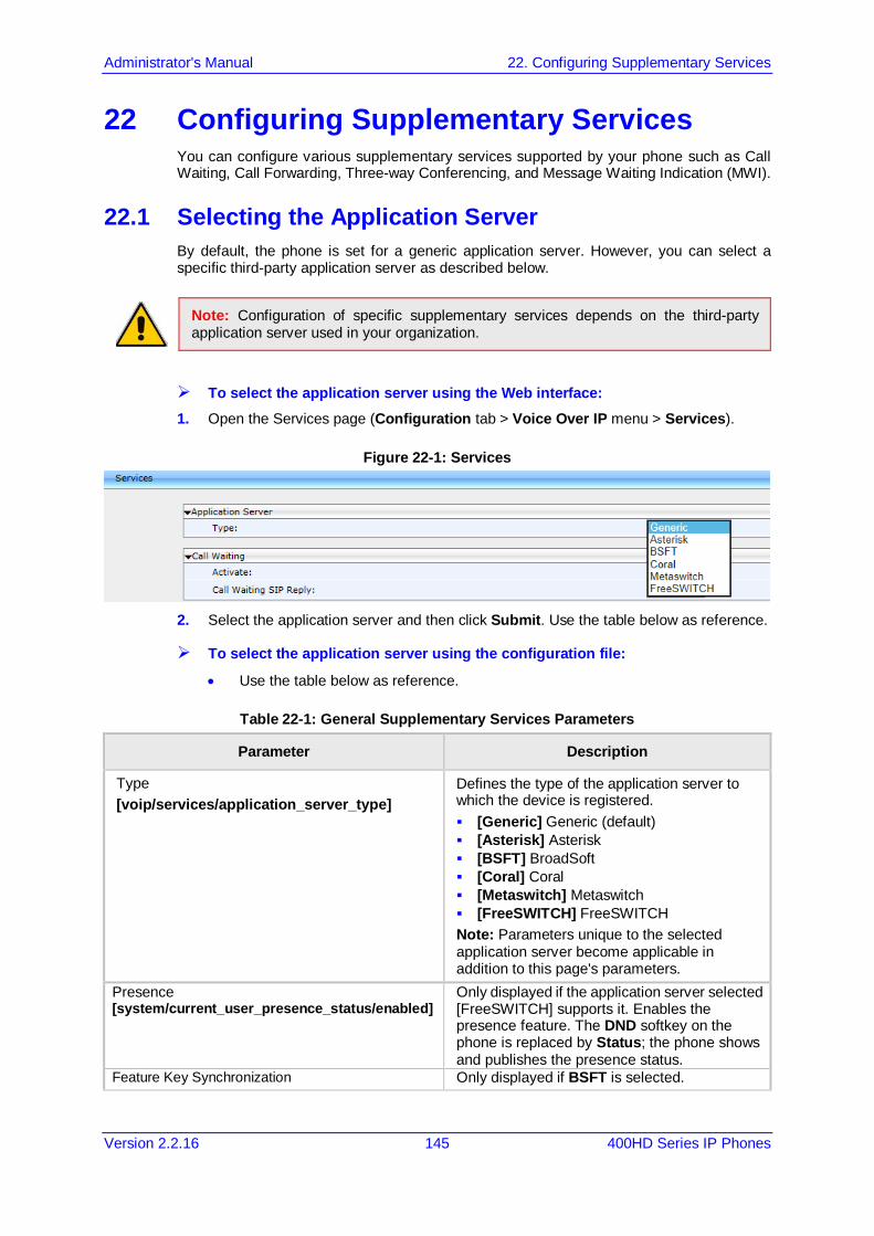
Administrator's Manual 22. Configuring Supplementary Services
Version 2.2.16 145 400HD Series IP Phones
22 Configuring Supplementary Services You can configure various supplementary services supported by your phone such as Call Waiting, Call Forwarding, Three-way Conferencing, and Message Waiting Indication (MWI).
22.1 Selecting the Application Server By default, the phone is set for a generic application server. However, you can select a specific third-party application server as described below.
Note: Configuration of specific supplementary services depends on the third-party application server used in your organization.
To select the application server using the Web interface: 1. Open the Services page (Configuration tab > Voice Over IP menu > Services).
Figure 22-1: Services
2. Select the application server and then click Submit. Use the table below as reference.
To select the application server using the configuration file:
• Use the table below as reference.
Table 22-1: General Supplementary Services Parameters
Parameter Description
Type [voip/services/application_server_type]
Defines the type of the application server to which the device is registered. [Generic] Generic (default) [Asterisk] Asterisk [BSFT] BroadSoft [Coral] Coral [Metaswitch] Metaswitch [FreeSWITCH] FreeSWITCH Note: Parameters unique to the selected application server become applicable in addition to this page's parameters.
Presence [system/current_user_presence_status/enabled]
Only displayed if the application server selected [FreeSWITCH] supports it. Enables the presence feature. The DND softkey on the phone is replaced by Status; the phone shows and publishes the presence status.
Feature Key Synchronization Only displayed if BSFT is selected.
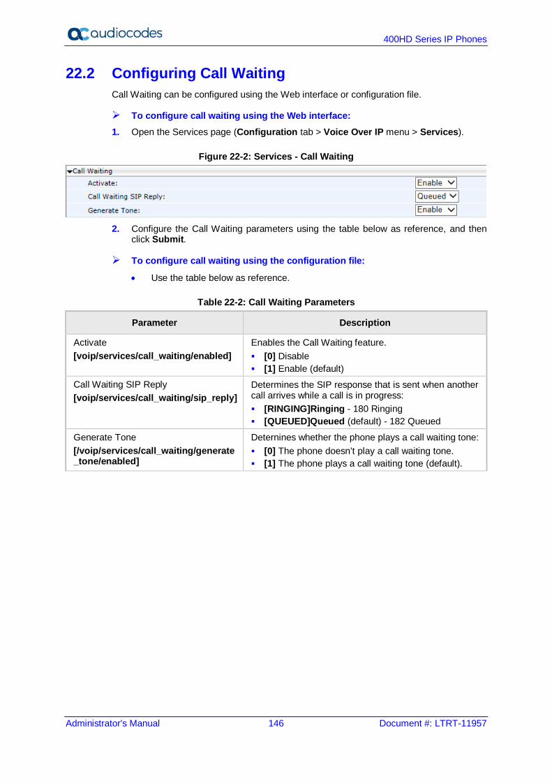
400HD Series IP Phones
Administrator's Manual 146 Document #: LTRT-11957
22.2 Configuring Call Waiting Call Waiting can be configured using the Web interface or configuration file.
To configure call waiting using the Web interface: 1. Open the Services page (Configuration tab > Voice Over IP menu > Services).
Figure 22-2: Services - Call Waiting
2. Configure the Call Waiting parameters using the table below as reference, and then
click Submit.
To configure call waiting using the configuration file:
• Use the table below as reference.
Table 22-2: Call Waiting Parameters
Parameter Description
Activate [voip/services/call_waiting/enabled]
Enables the Call Waiting feature. [0] Disable [1] Enable (default)
Call Waiting SIP Reply [voip/services/call_waiting/sip_reply]
Determines the SIP response that is sent when another call arrives while a call is in progress: [RINGING]Ringing - 180 Ringing [QUEUED]Queued (default) - 182 Queued
Generate Tone [/voip/services/call_waiting/generate_tone/enabled]
Deternines whether the phone plays a call waiting tone: [0] The phone doesn’t play a call waiting tone. [1] The phone plays a call waiting tone (default).

Administrator's Manual 22. Configuring Supplementary Services
Version 2.2.16 147 400HD Series IP Phones
22.3 Configuring Call Forwarding Call Forwarding can be configured using the Web interface, configuration file, or phone screen. In a BroadSoft environment, Call Forwarding can be configured in the BroadSoft BroadWorks application server (see under Appendix A for detailed information).
To configure call forwarding using the Web interface: 1. Open the Services page (Configuration tab > Voice Over IP menu > Services).
Figure 22-3: Services - Call Forward
2. Configure the Call Forwarding parameters using the table below as reference, and then
click Submit.
To configure call forwarding using the configuration file:
• Use the table below as reference.
Table 22-3: Call Forward Parameters
Parameter Description
Enable [voip/line/%d/call_forward/enabled]
Enables the Call Forward feature. [0] Disable [1] Enable (default)
Activate [voip/line/%d/call_forward/active]
Activates call forwarding, if it was enabled with the parameter above. [0] (default) - Disable [1] Enable Note: Call Forwarding is typically activated on the phone screen (see the User's Manual).
Call Forward Type [voip/line/%d/call_forward/type]
Determines the condition on which incoming calls are forwarded to another destination: [Unconditional] Unconditional - incoming calls are
forwarded independently of the status of the line. [Busy] Busy- incoming calls are forwarded only if
the phone is busy. [No_Reply] No Reply (default) - incoming calls are
forwarded only if the phone does not answer before a user-defined timeout.
Forward on No Reply Timeout [voip/line/%d/call_forward/timeout]
If calls are forwarded when the condition is No-Reply, then this parameter defines the time (in seconds) after which incoming calls are forwarded when this is no reply. Range:0 - 7200. Default: 6.
Forward Destination [voip/line/%d/call_forward/destination]
The destination to which the call is directed when call forward is activated.

400HD Series IP Phones
Administrator's Manual 148 Document #: LTRT-11957
To configure call forwarding using the phone's screen: See the User's Manual for detailed information.

Administrator's Manual 22. Configuring Supplementary Services
Version 2.2.16 149 400HD Series IP Phones
22.4 Configuring a Conference Three-way conferencing can be configured using the Web interface or configuration file.
To configure three-way conferencing using the Web interface: 1. Open the Services page (Configuration tab > Voice Over IP menu > Services).
Figure 22-4: Services - Conference
2. Configure the conferencing parameters using the table below as reference, and then
click Submit.
To configure three-way conferencing using the configuration file:
• Use the table below as reference.
Table 22-4: Conference Parameters
Parameter Description
Mode [/voip/services/conference/mode]
Sets the conference mode (when establishing 3-Way Conference). [LOCAL] = phone will establish the conference by itself. [REMOTE] = phone will use remote media server to establish the conference.
Remote Conference Media Server [/voip/services/conference/conf_ms_addr]
Relevant only if 'Mode'(above) is REMOTE. Defines the media server for establishing remote conference.
For more information on this feature, see RFC 4579, Session Initiation Protocol (SIP) - Call Control - Conferencing for User Agents.
22.5 Allowing the Initiator to Drop out of a Conference The phone can be configured to allow the initiator of a 3-way conference to drop out the conference when they on-hook the phone.
To configure the capability using the configuration file:
• Use the table below as reference.
Table 22-5: Allowing a Conference Initiator to Drop Out when On-Hooking
Parameter Description
[voip/drop_from_3wc_when_on_hook] Allows the initiator of a 3-way conference to drop out of the conference when they on-hook the phone. [0] = The initiator won't drop out of the conference when they on-hook the phone. [1] = The initiator will drop out of the conference when they on-hook the phone.

400HD Series IP Phones
Administrator's Manual 150 Document #: LTRT-11957
22.6 Configuring Automatic Dialing Automatic Dialing can be configured using the Web interface or configuration file.
To define Automatic Dialing using the Web interface: 1. Open the Dialing page (Configuration tab > Voice Over IP menu > Dialing).
Figure 22-5: Dialing - Automatic Dialing
2. Configure dialing options according to the parameters in the table below, and then click
Submit.
To define Automatic Dialing using the configuration file:
• Use the table below as reference.
Table 22-6: Automatic Dialing Parameters
Parameter Description
Activate [voip/dialing/auto_dialing/enabled]
Determines whether automatic dialing is enabled (i.e., phone number is automatically dialed when you off-hook the phone). [0] Disable (default) [1] Enable
Timeout [voip/dialing/auto_dialing/timeout]
Timeout (in seconds) before automatic dialing occurs after the phone is off-hooked. When set to 0, automatic dialing is performed immediately. The valid range is 0 to 120. The default value is 15.
Destination Phone Number [voip/dialing/auto_dialing/destination]
The number that is automatically dialed when the phone is off-hooked. The valid value can be up to 32 characters.

Administrator's Manual 22. Configuring Supplementary Services
Version 2.2.16 151 400HD Series IP Phones
22.7 Configuring Automatic Answer The Automatic Answer feature is configured using the configuration file. Use the table below as reference.
Table 22-7: Automatic Answer Parameters
Parameter Description
[voip/auto_answer/enabled] Enables the Automatic Answering feature. [0] Disable (default) [1] Enable When this parameter is enabled and an incoming SIP INVITE message is received containing information that informs the phone to automatically answer the call, the phone answers the call immediately or after a timeout, depending on the auto-answer type specified in the INVITE message: Phone answers after a timeout: The phone
automatically answers the call after a timeout if the INVITE message includes a SIP Call-Info header with a tag value, answer-after= set to a number representing the timeout. During the timeout interval, the phone rings normally. If the call is answered or rejected during this interval, then the automatic answering mechanism is not used. However, if the phone is left to ring throughout the timeout interval, it automatically answers the call once this timeout expires.
Phone answers immediately: The phone answers the call immediately in any of the following cases: If the SIP Alert-Info header contains the tag
value ring answer. If the SIP Alert-Info header contains the tag
value info=alert-autoanswer. Note: If the SIP Call-Info header includes all the above
answer types or any two different types (i.e., answer-after=, ring answer, and alert-autoanswer), the answer-after= type takes precedence.
If there is an existing call when an INVITE message for automatic answer is received, the existing call is automatically put on hold.
[voip/talk_event/enabled] Enables the 'talk' event feature. [0] Disable (default) [1] Enable The phone automatically answers an incoming call if it receives a SIP NOTIFY message with the 'talk' event. If a call is already in progress, the call is put on hold and the incoming call is answered.
[voip/advanced_auto_answer/timeout] The timeout before the call is answered (in seconds). Range: 0 – 60 (seconds)

400HD Series IP Phones
Administrator's Manual 152 Document #: LTRT-11957
Parameter Description
[5] = 5 seconds (default) [0] = immediately
[voip/advanced_auto_answer/type] SIP_Header (default) = identical to the parameter 'voip/auto_answer/enabled' described above
Manual = the phone automatically answers incoming calls according to the timeout configured in the 'voip/advanced_auto_answer/timeout' parameter
voip/auto_answer_use_180/enabled=0 Determines whether or not the phone will ring before auto answer, or if auto answer will occur immediately, before the phone rings. [0] Disable (default) = No ringing occurs before auto
answer; auto answer occurs immediately [1] Enable – Ringing occurs before auto answer
Note:
• The configuration file parameter ‘voip/auto_answer/enabled’ must be set to 1 to support the following: √ voip/advanced_auto_answer/timeout √ voip/advanced_auto_answer/type √ voip/auto_answer_use_180/enabled

Administrator's Manual 22. Configuring Supplementary Services
Version 2.2.16 153 400HD Series IP Phones
22.8 Configuring Do Not Disturb (DnD) The Do not Disturb (DnD) feature can be configured using the Web interface or configuration file. It can also be configured in BroadSoft's BroadWorks (see under Appendix A.1.3).
To configure DnD using the Web interface: 1. Open the Services page (Configuration tab > Voice Over IP menu > Services).
Figure 22-6: Services - DnD
2. Configure using the table below as reference, and then click Submit.
To configure DnD using the configuration file:
• Use the table below as reference.
Table 22-8: Do Not Disturb Parameters
Parameter Description
Enable [voip/services/do_not_disturb/enabled]
Enables the DnD feature. [0] Disable [1] Enable (default)
Activate [voip/line/%d/do_not_disturb/activated]
Activates the DnD feature per phone line, if the parameter 'voip/services/do_not_disturb/enabled' is enabled. [0] – Deactivate (default) [1] - Activate Three DnD configurations are possible in phones' idle screens: (1) If DnD is disabled, no notification will be displayed (2) If DnD is enabled for one line extension, one notification is displayed (3) If DnD is configured for two line extensions, two notifications are displayed. Note: DnD can also be activated in the phone's screen (more common).
To configure DnD on the phone: See the phone's User's Manual for detailed information.
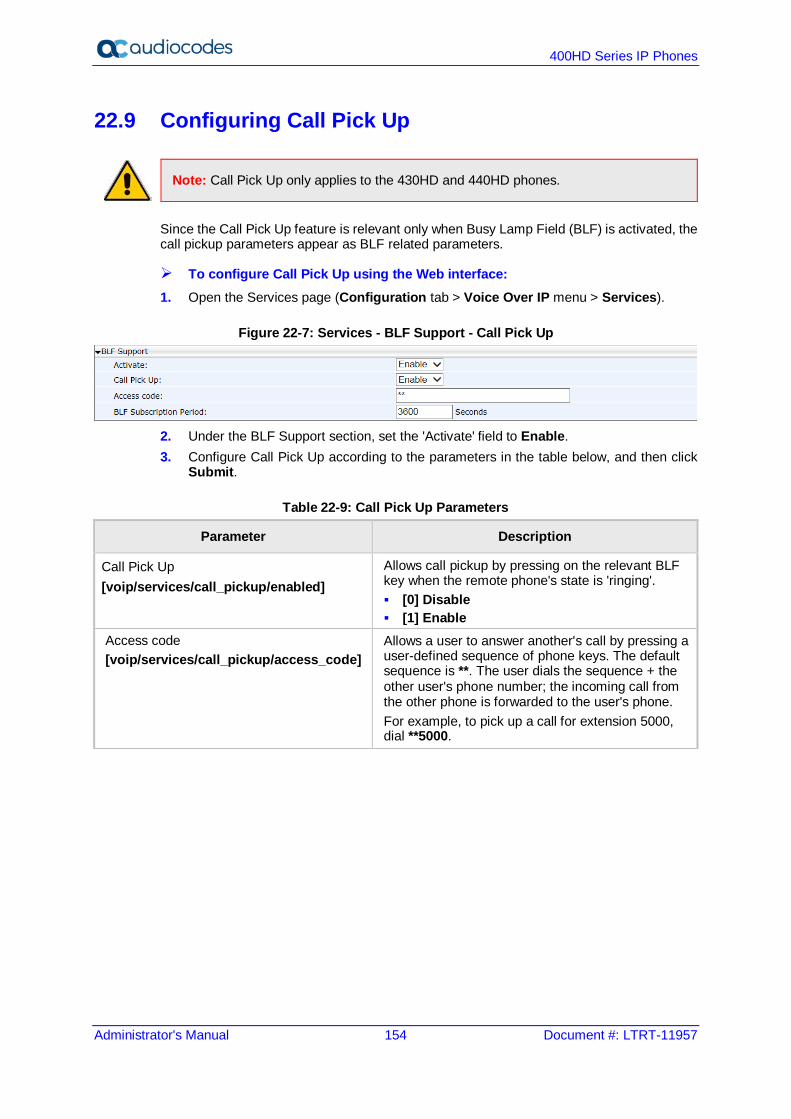
400HD Series IP Phones
Administrator's Manual 154 Document #: LTRT-11957
22.9 Configuring Call Pick Up
Note: Call Pick Up only applies to the 430HD and 440HD phones.
Since the Call Pick Up feature is relevant only when Busy Lamp Field (BLF) is activated, the call pickup parameters appear as BLF related parameters.
To configure Call Pick Up using the Web interface: 1. Open the Services page (Configuration tab > Voice Over IP menu > Services).
Figure 22-7: Services - BLF Support - Call Pick Up
2. Under the BLF Support section, set the 'Activate' field to Enable. 3. Configure Call Pick Up according to the parameters in the table below, and then click
Submit.
Table 22-9: Call Pick Up Parameters
Parameter Description
Call Pick Up [voip/services/call_pickup/enabled]
Allows call pickup by pressing on the relevant BLF key when the remote phone's state is 'ringing'. [0] Disable [1] Enable
Access code [voip/services/call_pickup/access_code]
Allows a user to answer another's call by pressing a user-defined sequence of phone keys. The default sequence is **. The user dials the sequence + the other user's phone number; the incoming call from the other phone is forwarded to the user's phone. For example, to pick up a call for extension 5000, dial **5000.
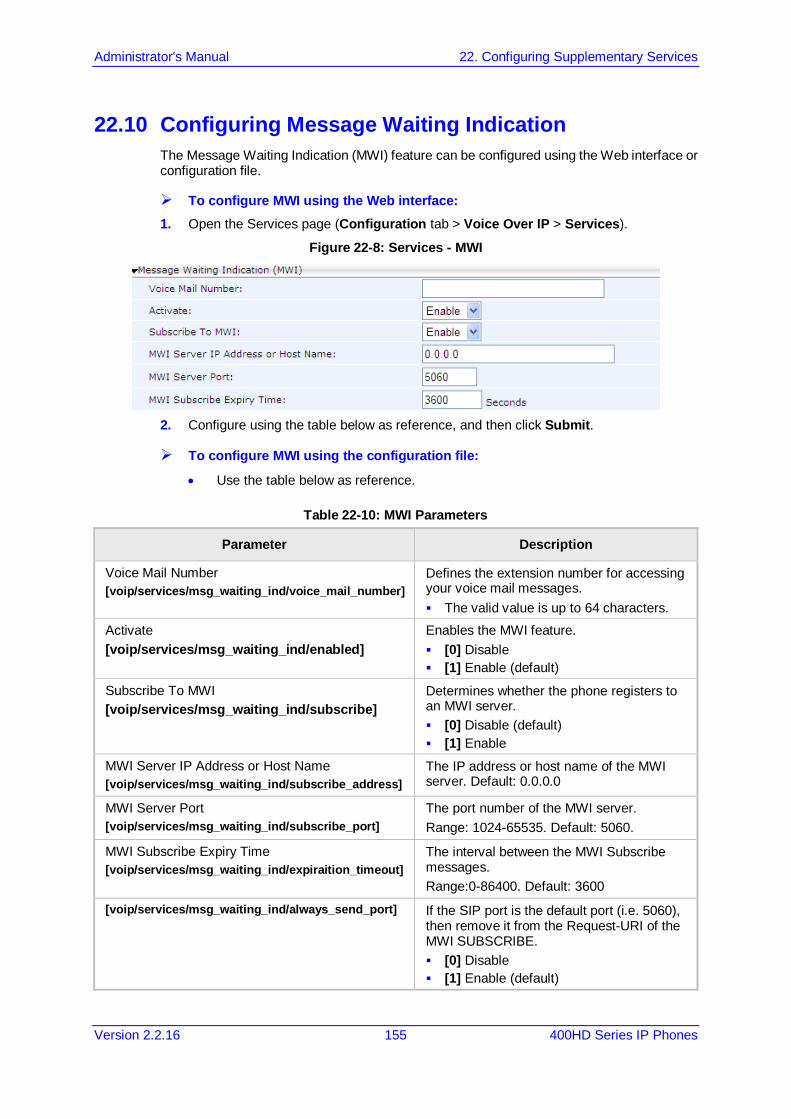
Administrator's Manual 22. Configuring Supplementary Services
Version 2.2.16 155 400HD Series IP Phones
22.10 Configuring Message Waiting Indication The Message Waiting Indication (MWI) feature can be configured using the Web interface or configuration file.
To configure MWI using the Web interface: 1. Open the Services page (Configuration tab > Voice Over IP > Services).
Figure 22-8: Services - MWI
2. Configure using the table below as reference, and then click Submit.
To configure MWI using the configuration file:
• Use the table below as reference.
Table 22-10: MWI Parameters
Parameter Description
Voice Mail Number [voip/services/msg_waiting_ind/voice_mail_number]
Defines the extension number for accessing your voice mail messages. The valid value is up to 64 characters.
Activate [voip/services/msg_waiting_ind/enabled]
Enables the MWI feature. [0] Disable [1] Enable (default)
Subscribe To MWI [voip/services/msg_waiting_ind/subscribe]
Determines whether the phone registers to an MWI server. [0] Disable (default) [1] Enable
MWI Server IP Address or Host Name [voip/services/msg_waiting_ind/subscribe_address]
The IP address or host name of the MWI server. Default: 0.0.0.0
MWI Server Port [voip/services/msg_waiting_ind/subscribe_port]
The port number of the MWI server. Range: 1024-65535. Default: 5060.
MWI Subscribe Expiry Time [voip/services/msg_waiting_ind/expiraition_timeout]
The interval between the MWI Subscribe messages. Range:0-86400. Default: 3600
[voip/services/msg_waiting_ind/always_send_port] If the SIP port is the default port (i.e. 5060), then remove it from the Request-URI of the MWI SUBSCRIBE. [0] Disable [1] Enable (default)
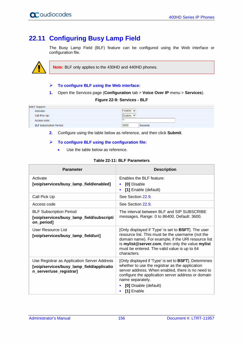
400HD Series IP Phones
Administrator's Manual 156 Document #: LTRT-11957
22.11 Configuring Busy Lamp Field The Busy Lamp Field (BLF) feature can be configured using the Web interface or configuration file.
Note: BLF only applies to the 430HD and 440HD phones.
To configure BLF using the Web interface: 1. Open the Services page (Configuration tab > Voice Over IP menu > Services).
Figure 22-9: Services - BLF
2. Configure using the table below as reference, and then click Submit.
To configure BLF using the configuration file:
• Use the table below as reference.
Table 22-11: BLF Parameters
Parameter Description
Activate [voip/services/busy_lamp_field/enabled]
Enables the BLF feature: [0] Disable [1] Enable (default)
Call Pick Up See Section 22.9.
Access code See Section 22.9.
BLF Subscription Period [voip/services/busy_lamp_field/subscription_period]
The interval between BLF and SIP SUBSCRIBE messages. Range: 0 to 86400. Default: 3600.
User Resource List [voip/services/busy_lamp_field/uri]
[Only displayed if 'Type' is set to BSFT]. The user resource list. This must be the username (not the domain name). For example, if the URI resource list is [email protected], then only the value mylist must be entered. The valid value is up to 64 characters.
Use Registrar as Application Server Address [voip/services/busy_lamp_field/application_server/use_registrar]
[Only displayed if 'Type' is set to BSFT]. Determines whether to use the registrar as the application server address. When enabled, there is no need to configure the application server address or domain name separately. [0] Disable (default) [1] Enable
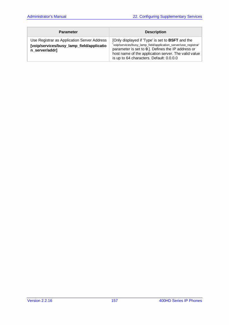
Administrator's Manual 22. Configuring Supplementary Services
Version 2.2.16 157 400HD Series IP Phones
Parameter Description
Use Registrar as Application Server Address [voip/services/busy_lamp_field/application_server/addr]
[Only displayed if 'Type' is set to BSFT and the 'voip/services/busy_lamp_field/application_server/use_registrar' parameter is set to 0.]. Defines the IP address or host name of the application server. The valid value is up to 64 characters. Default: 0.0.0.0
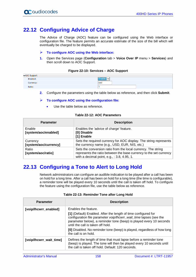
400HD Series IP Phones
Administrator's Manual 158 Document #: LTRT-11957
22.12 Configuring Advice of Charge The Advice of Charge (AOC) feature can be configured using the Web interface or configuration file. The feature permits an accurate estimate of the size of the bill which will eventually be charged to be displayed.
To configure AOC using the Web interface: 1. Open the Services page (Configuration tab > Voice Over IP menu > Services) and
then scroll down to AOC Support.
Figure 22-10: Services – AOC Support
2. Configure the parameters using the table below as reference, and then click Submit.
To configure AOC using the configuration file:
• Use the table below as reference.
Table 22-12: AOC Parameters
Parameter Description
Enable [system/aoc/enabled]
Enables the 'advice of charge' feature. [0] Disable [1] Enable
Currency [system/aoc/currency]
Sets the required currency for AOC display. The string represents the currency name (e.g., USD, EUR, NIS, etc.)
Ratio [system/aoc/ratio]
Sets the conversion ratio from the local currency. The string represents the ratio between the base currency to the set currency with a decimal point, e.g., : 3.8, 4.95, 1.
22.13 Configuring a Tone to Alert to Long Hold Network administrators can configure an audible indication to be played after a call has been on hold for a long time. After a call has been on hold for a long time (the time is configurable), a reminder tone will be played every 10 seconds until the call is taken off hold. To configure the feature using the configuration file, use the table below as reference.
Table 22-13: Reminder Tone after Long Hold
Parameter Description
[voip/lhcwrr_enabled] Enables the feature. [1] (Default) Enabled. After the length of time configured for configuration file parameter voip/lhcwrr_wait_time lapses (see the parameter below), a reminder tone (beep) is played every 10 seconds until the call is taken off hold. [0] Disabled. No reminder tone (beep) is played, regardless of how long the call is on hold.
[voip/lhcwrr_wait_time] Defines the length of time that must lapse before a reminder tone (beep) is played. The tone will then be played every 10 seconds until the call is taken off hold. Default: 120 seconds.
Administrator's Manual 22. Configuring Supplementary Services
Version 2.2.16 159 400HD Series IP Phones
22.14 Disabling the HOLD Key The network administrator can disable hard keys and softkeys on phones using the configuration file. The feature is motivated by the requirement on the part of some enterprises to control settings remotely to comply with company policy. Here's how to disable the HOLD key on the phone's keypad.
To disable the HOLD key using the configuration file:
• Use the table below as reference.
Table 22-14: Disabling the HOLD Key
Parameter Description
[system/disable_hold_button] Disables the HOLD key on the phone's keypad. The HOLD key is used to place a call on hold, or to resume a held call.
Besides the HOLD key, other hard keys that can be disabled include speaker, headset, voicemail, REDIAL, CONTACTS, MENU, TRANSFER, VOL and mute. For more information, see Section 26.
22.15 Configuring Onhook Disconnect when Held
Note: Only applies to AudioCodes' SIP-100 and SIP-200 devices.
Here's how to configure whether the device automatically goes idle (i.e., on-hook) when the last remaining call is disconnected.
To configure onhook disconnect when held, using the configuration file:
• Use the table below as reference.
Table 22-15: Onhook Disconnect when Held
Parameter Description
[voip/onhook_disconnect_when_held/enabled] Choose either: [0] Disable (default) - If the receiver is placed on-hook
after a call is put on hold, the call is put on speaker rather; it isn't disconnected.
[1] Enable - If the receiver is placed on-hook after a call is put on hold, the call is disconnected.
400HD Series IP Phones
Administrator's Manual 160 Document #: LTRT-11957
22.16 Configuring Ringing on the Default Audio Device Here's how to configure whether ringing is heard on the default audio device.
To configure whether ringing is heard on the default audio device, using the configuration file:
• Use the table below as reference.
Table 22-16: Configuring Ringing on the Default Audio Device
Parameter Description
[voip/called_ringing_device] Determines which device rings when a call comes in. Configure either: SPEAKER (default) HEADSET BOTH NO_RING In call centers in which agents typically work close to one another wearing headsets, the administrator can configure HEADSET to prevent incoming calls ringing on speakers which creates a noisy environment. The parameter is bundled with the two parameters below ('hands_free_mode' and 'supervisor_listen_in') to maximize flexibility for call center administrators, who can - for example - disable ringing on the speaker yet enable hands-free mode (talking and listening using the speaker).
[voip/hands_free_mode/enabled] When disabled [0]: hands-free mode becomes unavailable pressing the speaker key does not have any effect when answering a call, the headset is the default
audio Configure: [1] = Enabled (default) [0] = Disabled
[voip/services/supervisor_listen_in/enabled]
If enabled, a call center supervisor can pick up an agent's handset and listen in on the conversation that the agent is conducting on headphones with the customer, without the customer at the other end sensing that the supervisor is listening in (because the supervisor is in effect muted). Configure: [1] = Enabled [0] = Disabled (default)
Administrator's Manual 22. Configuring Supplementary Services
Version 2.2.16 161 400HD Series IP Phones
22.17 Allowing an Incoming Call when the Phone is Locked Here's how to allow or not allow an incoming call when the phone is locked.
To allow an incoming call when the phone is locked, using the configuration file:
• Use the table below as reference.
Table 22-17: Allowing an Incoming Call when the Phone is Locked
Parameter Description
[system/lock/2-5/allow_incoming_calls] Allows incoming calls when the phone is locked (default). If allowed, the user will need to enter an unlock
password to answer an incoming call. If not allowed, the incoming call will be automatically
rejected by the phone. [system/lock/2-5/enabled] Enables the phone's lock feature. Relevant for
supporting servers only.
22.18 Allowing Call Center Agents to Record Welcome Greetings Here's how to let Call Center agents record welcome greetings.
To let Call Center agents record welcome greetings, using the configuration file:
• Use the table below as reference.
Table 22-18: Letting Call Center Agents Record Welcome Greetings
Parameter Description
[voip/services/greeting/beep/enabled] Enables a beep to be heard by the agent when the recorded welcome greeting finishes playing. [1] = Enabled (default) [0] = Disabled
[voip/services/greeting/enabled] Lets agents in a call center record directly on their phones personal voice greetings which play automatically when callers call in, to welcome callers to the service they’re seeking. Configure: [1] = Enabled [0] = Disabled (default)
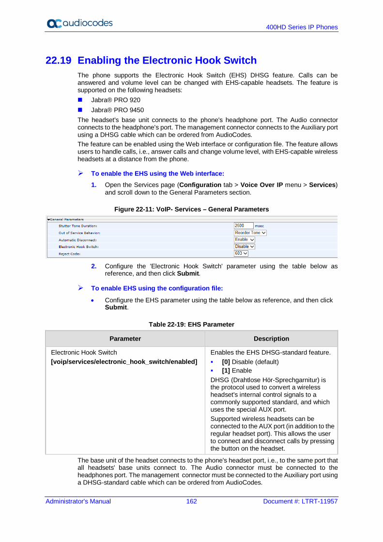
400HD Series IP Phones
Administrator's Manual 162 Document #: LTRT-11957
22.19 Enabling the Electronic Hook Switch The phone supports the Electronic Hook Switch (EHS) DHSG feature. Calls can be answered and volume level can be changed with EHS-capable headsets. The feature is supported on the following headsets: Jabra® PRO 920 Jabra® PRO 9450 The headset's base unit connects to the phone's headphone port. The Audio connector connects to the headphone's port. The management connector connects to the Auxiliary port using a DHSG cable which can be ordered from AudioCodes. The feature can be enabled using the Web interface or configuration file. The feature allows users to handle calls, i.e., answer calls and change volume level, with EHS-capable wireless headsets at a distance from the phone.
To enable the EHS using the Web interface: 1. Open the Services page (Configuration tab > Voice Over IP menu > Services)
and scroll down to the General Parameters section.
Figure 22-11: VoIP- Services – General Parameters
2. Configure the 'Electronic Hook Switch' parameter using the table below as
reference, and then click Submit.
To enable EHS using the configuration file:
• Configure the EHS parameter using the table below as reference, and then click Submit.
Table 22-19: EHS Parameter
Parameter Description
Electronic Hook Switch [voip/services/electronic_hook_switch/enabled]
Enables the EHS DHSG-standard feature. [0] Disable (default) [1] Enable DHSG (Drahtlose Hör-Sprechgarnitur) is the protocol used to convert a wireless headset's internal control signals to a commonly supported standard, and which uses the special AUX port. Supported wireless headsets can be connected to the AUX port (in addition to the regular headset port). This allows the user to connect and disconnect calls by pressing the button on the headset.
The base unit of the headset connects to the phone's headset port, i.e., to the same port that all headsets' base units connect to. The Audio connector must be connected to the headphones port. The management connector must be connected to the Auxiliary port using a DHSG-standard cable which can be ordered from AudioCodes.
Administrator's Manual 22. Configuring Supplementary Services
Version 2.2.16 163 400HD Series IP Phones
22.20 Disabling the Hard Mute Key on the Phone The network administrator can disable the mute hard key on phones using the configuration file. The feature is motivated by the requirement on the part of some enterprises to control the key remotely to comply with company policy.
To disable the hard mute key on the phone using the configuration file:
• Use the table below as reference.
Table 22-20: Disabling the Hard Mute Key on the Phone
Parameter Description
[voip/block_mute_key] Allows network administrators to configure enabling or disabling the hard mute key on the phone. [0] (default) Allows the hard mute key
on the phone to function regularly. [1] Disables the hard mute key on the
phone. In addition to the mute key, hard keys that can be disabled include speaker, headset, voicemail, REDIAL, CONTACTS, MENU, TRANSFER, HOLD, and VOL. See also Section 26 for information about disabling these keys.
400HD Series IP Phones
Administrator's Manual 164 Document #: LTRT-11957
22.21 Configuring Attended and Semi-Attended Call Transfer Here's how to configure a softkey with attended and semi-attended call transfer functionality, using the configuration file.
To configure a softkey with attended / semi-attended call transfer functionality: Use the table below as reference:
Table 22-21: Configuring a Softkey with Attended and Semi-Attended Call Transfer Functionality
Parameter Description
[personal_settings/soft_keys/ongoing_call/0/key_function]
Default: Hold. Change it to TRANSFER to configure the softkey with attended / semi-attended call transfer functionality.
22.22 Configuring Blind Transfer You can configure a softkey with blind transfer functionality using the configuration file.
To configure a softkey with blind transfer functionality: Use the table below as reference:
Table 22-22: Configuring a Softkey with Blind Transfer Functionality
Parameter Description
[personal_settings/soft_keys/ongoing_call/0/key_function]
If you configure BLIND_TRANSFER, a softkey with blind transfer functionality will be displayed in the phone screen: On the 405/405HD phone (exclusively), the
softkey displayed will be BXfer. The 405/405HD phone does not feature a hard TRANSFER key like the other phones. This softkey enables that functionality.
On the other phones (besides the 405/405HD), the softkey displayed is HOLD.

Administrator's Manual 22. Configuring Supplementary Services
Version 2.2.16 165 400HD Series IP Phones
22.23 Creating a Speed Dial File for Configuration File The configuration file can include a link to a user-defined Speed Dial file, using the 'provisioning/speed_dial_uri' parameter. This allows you to upload speed dial settings to the phone. The Speed Dial file must include a list of speed dial configurations. The file must be a simple text file that can be created using an Excel document and saved as a CSV file. The syntax of the speed dial file is as follows: <memory key>,<speed dial phone number>,<type>
where: <memory key> is the speed dial memory key on the phone. <speed dial phone number> is the phone number that is automatically dialed, when the user presses the speed dial key. <type> denotes the Speed Dial feature and must be set to “0”. Below is an example of a Speed Dial file: 1,4418,0 2,4403,0 3,039764432,0 4,4391,0 12,1234,0

400HD Series IP Phones
Administrator's Manual 166 Document #: LTRT-11957
This page is intentionally left blank.
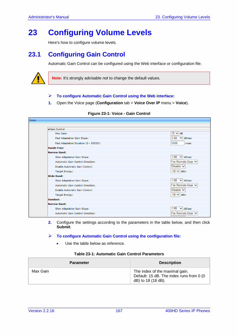
Administrator's Manual 23. Configuring Volume Levels
Version 2.2.16 167 400HD Series IP Phones
23 Configuring Volume Levels Here's how to configure volume levels.
23.1 Configuring Gain Control Automatic Gain Control can be configured using the Web interface or configuration file.
Note: It's strongly advisable not to change the default values.
To configure Automatic Gain Control using the Web interface: 1. Open the Voice page (Configuration tab > Voice Over IP menu > Voice).
Figure 23-1: Voice - Gain Control
2. Configure the settings according to the parameters in the table below, and then click
Submit.
To configure Automatic Gain Control using the configuration file:
• Use the table below as reference.
Table 23-1: Automatic Gain Control Parameters
Parameter Description
Max Gain The index of the maximal gain. Default: 15 dB. The index runs from 0 (0 dB) to 18 (18 dB).
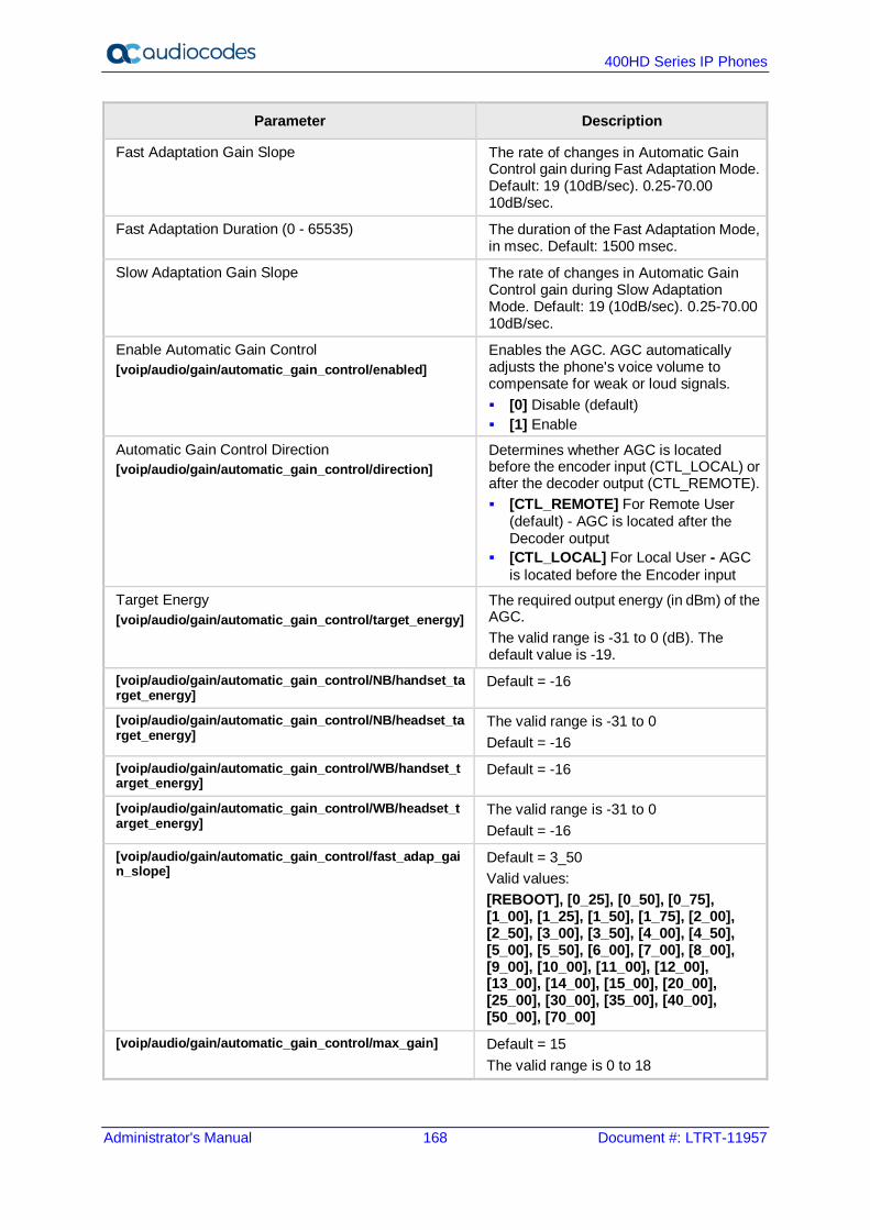
400HD Series IP Phones
Administrator's Manual 168 Document #: LTRT-11957
Parameter Description
Fast Adaptation Gain Slope The rate of changes in Automatic Gain Control gain during Fast Adaptation Mode. Default: 19 (10dB/sec). 0.25-70.00 10dB/sec.
Fast Adaptation Duration (0 - 65535) The duration of the Fast Adaptation Mode, in msec. Default: 1500 msec.
Slow Adaptation Gain Slope The rate of changes in Automatic Gain Control gain during Slow Adaptation Mode. Default: 19 (10dB/sec). 0.25-70.00 10dB/sec.
Enable Automatic Gain Control [voip/audio/gain/automatic_gain_control/enabled]
Enables the AGC. AGC automatically adjusts the phone's voice volume to compensate for weak or loud signals. [0] Disable (default) [1] Enable
Automatic Gain Control Direction [voip/audio/gain/automatic_gain_control/direction]
Determines whether AGC is located before the encoder input (CTL_LOCAL) or after the decoder output (CTL_REMOTE). [CTL_REMOTE] For Remote User
(default) - AGC is located after the Decoder output
[CTL_LOCAL] For Local User - AGC is located before the Encoder input
Target Energy [voip/audio/gain/automatic_gain_control/target_energy]
The required output energy (in dBm) of the AGC. The valid range is -31 to 0 (dB). The default value is -19.
[voip/audio/gain/automatic_gain_control/NB/handset_target_energy]
Default = -16
[voip/audio/gain/automatic_gain_control/NB/headset_target_energy]
The valid range is -31 to 0 Default = -16
[voip/audio/gain/automatic_gain_control/WB/handset_target_energy]
Default = -16
[voip/audio/gain/automatic_gain_control/WB/headset_target_energy]
The valid range is -31 to 0 Default = -16
[voip/audio/gain/automatic_gain_control/fast_adap_gain_slope]
Default = 3_50 Valid values: [REBOOT], [0_25], [0_50], [0_75], [1_00], [1_25], [1_50], [1_75], [2_00], [2_50], [3_00], [3_50], [4_00], [4_50], [5_00], [5_50], [6_00], [7_00], [8_00], [9_00], [10_00], [11_00], [12_00], [13_00], [14_00], [15_00], [20_00], [25_00], [30_00], [35_00], [40_00], [50_00], [70_00]
[voip/audio/gain/automatic_gain_control/max_gain] Default = 15 The valid range is 0 to 18

Administrator's Manual 23. Configuring Volume Levels
Version 2.2.16 169 400HD Series IP Phones
23.2 Configuring Tone Volume Tone volume can be configured using the configuration file.
Note: It's strongly advisable not to change the default values.
To configure tone volume using the configuration file:
• Use the table below as reference.
Table 23-2: Tone Volume Parameter
Parameter Description
Tone Volume [voip/audio/gain/tone_signal_level]
Call Progress Tone volume. This volume can be modified on-the-fly by pressing the phone's VOLUME key in certain scenarios. The valid range is 1 to 31 (-dB). The default value is 10 (-10dB).
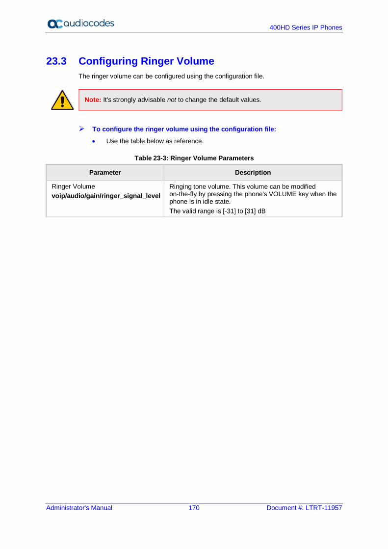
400HD Series IP Phones
Administrator's Manual 170 Document #: LTRT-11957
23.3 Configuring Ringer Volume The ringer volume can be configured using the configuration file.
Note: It's strongly advisable not to change the default values.
To configure the ringer volume using the configuration file:
• Use the table below as reference.
Table 23-3: Ringer Volume Parameters
Parameter Description
Ringer Volume voip/audio/gain/ringer_signal_level
Ringing tone volume. This volume can be modified on-the-fly by pressing the phone's VOLUME key when the phone is in idle state. The valid range is [-31] to [31] dB
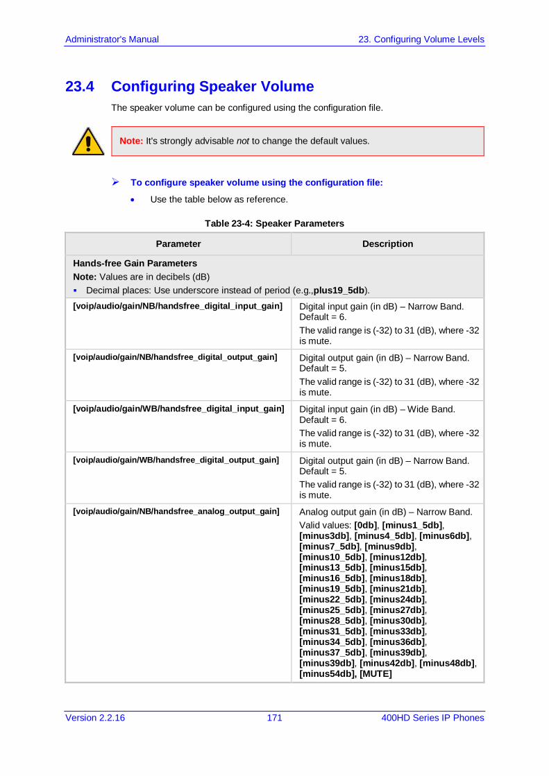
Administrator's Manual 23. Configuring Volume Levels
Version 2.2.16 171 400HD Series IP Phones
23.4 Configuring Speaker Volume The speaker volume can be configured using the configuration file.
Note: It's strongly advisable not to change the default values.
To configure speaker volume using the configuration file:
• Use the table below as reference.
Table 23-4: Speaker Parameters
Parameter Description
Hands-free Gain Parameters Note: Values are in decibels (dB) Decimal places: Use underscore instead of period (e.g.,plus19_5db). [voip/audio/gain/NB/handsfree_digital_input_gain] Digital input gain (in dB) – Narrow Band.
Default = 6. The valid range is (-32) to 31 (dB), where -32 is mute.
[voip/audio/gain/NB/handsfree_digital_output_gain] Digital output gain (in dB) – Narrow Band. Default = 5. The valid range is (-32) to 31 (dB), where -32 is mute.
[voip/audio/gain/WB/handsfree_digital_input_gain] Digital input gain (in dB) – Wide Band. Default = 6. The valid range is (-32) to 31 (dB), where -32 is mute.
[voip/audio/gain/WB/handsfree_digital_output_gain] Digital output gain (in dB) – Narrow Band. Default = 5. The valid range is (-32) to 31 (dB), where -32 is mute.
[voip/audio/gain/NB/handsfree_analog_output_gain] Analog output gain (in dB) – Narrow Band. Valid values: [0db], [minus1_5db], [minus3db], [minus4_5db], [minus6db], [minus7_5db], [minus9db], [minus10_5db], [minus12db], [minus13_5db], [minus15db], [minus16_5db], [minus18db], [minus19_5db], [minus21db], [minus22_5db], [minus24db], [minus25_5db], [minus27db], [minus28_5db], [minus30db], [minus31_5db], [minus33db], [minus34_5db], [minus36db], [minus37_5db], [minus39db], [minus39db], [minus42db], [minus48db], [minus54db], [MUTE]

400HD Series IP Phones
Administrator's Manual 172 Document #: LTRT-11957
Parameter Description
[voip/audio/gain/WB/handsfree_analog_output_gain] Analog output gain (in dB) – Wide Band. Valid values: [0db] (default), [minus1_5db], [minus3db], [minus4_5db], [minus6db], [minus7_5db], [minus9db], [minus10_5db], [minus12db], [minus13_5db], [minus15db], [minus16_5db], [minus18db], [minus19_5db], [minus21db], [minus22_5db], [minus24db], [minus25_5db], [minus27db], [minus28_5db], [minus30db], [minus31_5db], [minus33db], [minus34_5db], [minus36db], [minus37_5db], [minus39db], [minus39db], [minus42db], [minus48db], [minus54db], [MUTE]
[voip/audio/gain/NB/handsfree_analog_input_gain] Analog input gain (in dB) – Narrow Band Valid values: [0db], [plus1_5db], [plus3db], [plus4_5db], [plus6db], [plus7_5db], [plus9db], [plus10_5db], [plus12db], [plus13_5db], [plus15db], [plus16_5db], [plus18db], [plus19_5db], [plus21db], [plus22_5db], [plus24db], [plus25_5db], [plus27db], [plus28_5db], [plus30db], [plus31_5db], [plus33db], [plus34_5db], [plus36db], [plus37_5db], [plus39db], [plus40_5db], [PLUS42DB] (default), [plus48db], [plus54db], [MUTE]
[voip/audio/gain/WB/handsfree_analog_input_gain] Analog input gain (in dB) – Wide Band. Valid values: [0db], [plus1_5db], [plus3db], [plus4_5db], [plus6db], [plus7_5db], [plus9db], [plus10_5db], [plus12db], [plus13_5db], [plus15db], [plus16_5db], [plus18db], [plus19_5db], [plus21db], [plus22_5db], [plus24db], [plus25_5db], [plus27db], [plus28_5db], [plus30db], [plus31_5db], [plus33db], [plus34_5db], [plus36db], [plus37_5db], [plus39db], [plus40_5db], [PLUS42DB] (default), [plus48db], [plus54db], [MUTE]
[voip/audio/gain/NB/additional_speaker_gain] Additional parameter for speaker gain configuration, for Narrow Band. Valid values: [0] 0dB [1] 1dB [2] 2dB [3] 3Db (default)
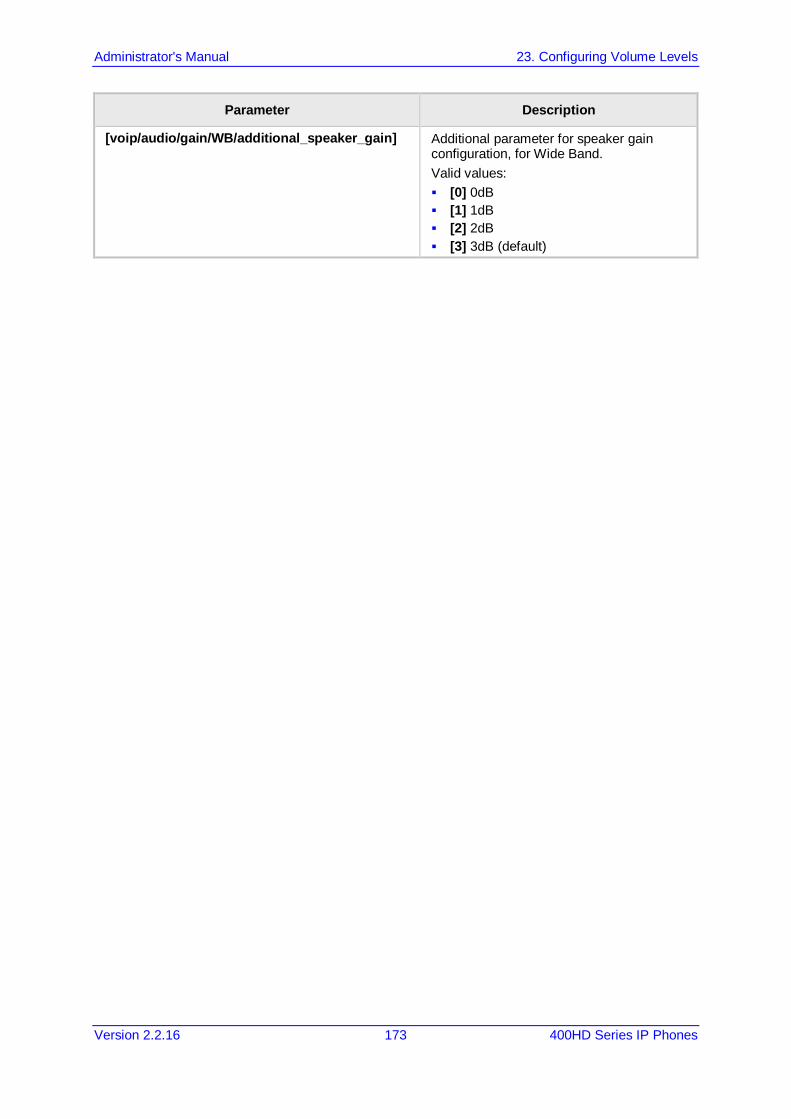
Administrator's Manual 23. Configuring Volume Levels
Version 2.2.16 173 400HD Series IP Phones
Parameter Description
[voip/audio/gain/WB/additional_speaker_gain] Additional parameter for speaker gain configuration, for Wide Band. Valid values: [0] 0dB [1] 1dB [2] 2dB [3] 3dB (default)
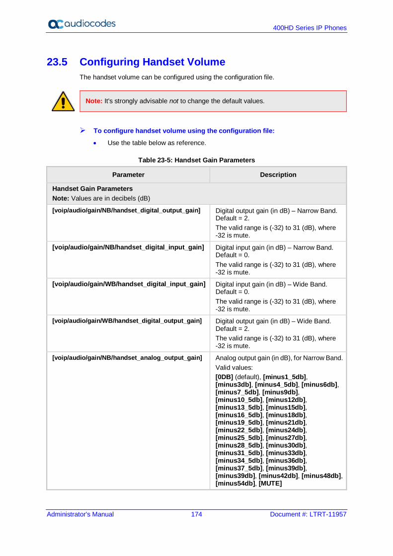
400HD Series IP Phones
Administrator's Manual 174 Document #: LTRT-11957
23.5 Configuring Handset Volume The handset volume can be configured using the configuration file.
Note: It's strongly advisable not to change the default values.
To configure handset volume using the configuration file:
• Use the table below as reference.
Table 23-5: Handset Gain Parameters
Parameter Description
Handset Gain Parameters Note: Values are in decibels (dB)
[voip/audio/gain/NB/handset_digital_output_gain] Digital output gain (in dB) – Narrow Band. Default = 2. The valid range is (-32) to 31 (dB), where -32 is mute.
[voip/audio/gain/NB/handset_digital_input_gain] Digital input gain (in dB) – Narrow Band. Default = 0. The valid range is (-32) to 31 (dB), where -32 is mute.
[voip/audio/gain/WB/handset_digital_input_gain] Digital input gain (in dB) – Wide Band. Default = 0. The valid range is (-32) to 31 (dB), where -32 is mute.
[voip/audio/gain/WB/handset_digital_output_gain] Digital output gain (in dB) – Wide Band. Default = 2. The valid range is (-32) to 31 (dB), where -32 is mute.
[voip/audio/gain/NB/handset_analog_output_gain] Analog output gain (in dB), for Narrow Band. Valid values: [0DB] (default), [minus1_5db], [minus3db], [minus4_5db], [minus6db], [minus7_5db], [minus9db], [minus10_5db], [minus12db], [minus13_5db], [minus15db], [minus16_5db], [minus18db], [minus19_5db], [minus21db], [minus22_5db], [minus24db], [minus25_5db], [minus27db], [minus28_5db], [minus30db], [minus31_5db], [minus33db], [minus34_5db], [minus36db], [minus37_5db], [minus39db], [minus39db], [minus42db], [minus48db], [minus54db], [MUTE]
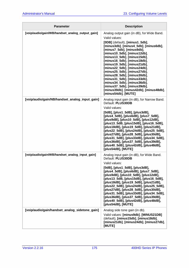
Administrator's Manual 23. Configuring Volume Levels
Version 2.2.16 175 400HD Series IP Phones
Parameter Description
[voip/audio/gain/WB/handset_analog_output_gain] Analog output gain (in dB), for Wide Band. Valid values: [0DB] (default), [minus1_5db], [minus3db], [minus4_5db], [minus6db], [minus7_5db], [minus9db], [minus10_5db], [minus12db], [minus13_5db], [minus15db], [minus16_5db], [minus18db], [minus19_5db], [minus21db], [minus22_5db], [minus24db], [minus25_5db], [minus27db], [minus28_5db], [minus30db], [minus31_5db], [minus33db], [minus34_5db], [minus36db], [minus37_5db], [minus39db], [minus39db], [minus42db], [minus48db], [minus54db], [MUTE]
[voip/audio/gain/NB/handset_analog_input_gain] Analog input gain (in dB), for Narrow Band. Default: PLUS30DB Valid values: [0dB], [plus1_5dB], [plus3dB], [plus4_5dB], [plus6dB], [plus7_5dB], [plus9dB], [plus10_5dB], [plus12dB], [plus13_5dB, [plus15dB], [plus16_5dB], [plus18dB], [plus19_5dB], [plus21dB], [plus22_5dB], [plus24dB], [plus25_5dB], [plus27dB], [plus28_5dB], [plus30dB], [plus31_5dB], [plus33dB], [plus34_5dB], [plus36dB], [plus37_5dB], [plus39dB], [plus40_5dB], [plus42dB], [plus48dB], [plus54dB], [MUTE]
[voip/audio/gain/WB/handset_analog_input_gain] Analog input gain (in dB), for Wide Band. Default: PLUS30DB Valid values: [0dB], [plus1_5dB], [plus3dB], [plus4_5dB], [plus6dB], [plus7_5dB], [plus9dB], [plus10_5dB], [plus12dB], [plus13_5dB, [plus15dB], [plus16_5dB], [plus18dB], [plus19_5dB], [plus21dB], [plus22_5dB], [plus24dB], [plus25_5dB], [plus27dB], [plus28_5dB], [plus30dB], [plus31_5dB], [plus33dB], [plus34_5dB], [plus36dB], [plus37_5dB], [plus39dB], [plus40_5dB], [plus42dB], [plus48dB], [plus54dB], [MUTE]
[voip/audio/gain/handset_analog_sidetone_gain] Analog side tone gain (in db). Valid values: [minus9db], [MINUS21DB] (default), [minus15db], [minus18db], [minus21db], [minus24db], [minus27db], [MUTE]
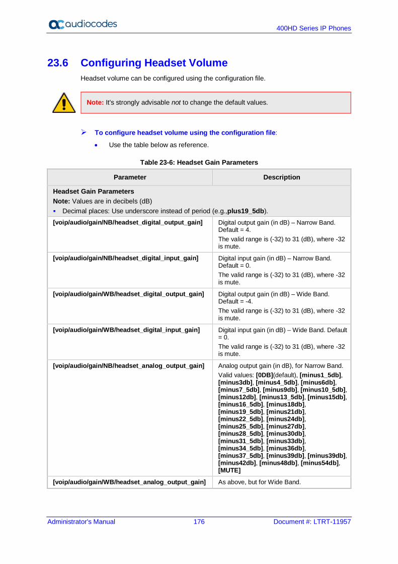
400HD Series IP Phones
Administrator's Manual 176 Document #: LTRT-11957
23.6 Configuring Headset Volume Headset volume can be configured using the configuration file.
Note: It's strongly advisable not to change the default values.
To configure headset volume using the configuration file:
• Use the table below as reference.
Table 23-6: Headset Gain Parameters
Parameter Description
Headset Gain Parameters Note: Values are in decibels (dB) Decimal places: Use underscore instead of period (e.g.,plus19_5db). [voip/audio/gain/NB/headset_digital_output_gain] Digital output gain (in dB) – Narrow Band.
Default = 4. The valid range is (-32) to 31 (dB), where -32 is mute.
[voip/audio/gain/NB/headset_digital_input_gain] Digital input gain (in dB) – Narrow Band. Default = 0. The valid range is (-32) to 31 (dB), where -32 is mute.
[voip/audio/gain/WB/headset_digital_output_gain] Digital output gain (in dB) – Wide Band. Default = -4. The valid range is (-32) to 31 (dB), where -32 is mute.
[voip/audio/gain/WB/headset_digital_input_gain] Digital input gain (in dB) – Wide Band. Default = 0. The valid range is (-32) to 31 (dB), where -32 is mute.
[voip/audio/gain/NB/headset_analog_output_gain] Analog output gain (in dB), for Narrow Band. Valid values: [0DB](default), [minus1_5db], [minus3db], [minus4_5db], [minus6db], [minus7_5db], [minus9db], [minus10_5db], [minus12db], [minus13_5db], [minus15db], [minus16_5db], [minus18db], [minus19_5db], [minus21db], [minus22_5db], [minus24db], [minus25_5db], [minus27db], [minus28_5db], [minus30db], [minus31_5db], [minus33db], [minus34_5db], [minus36db], [minus37_5db], [minus39db], [minus39db], [minus42db], [minus48db], [minus54db], [MUTE]
[voip/audio/gain/WB/headset_analog_output_gain] As above, but for Wide Band.
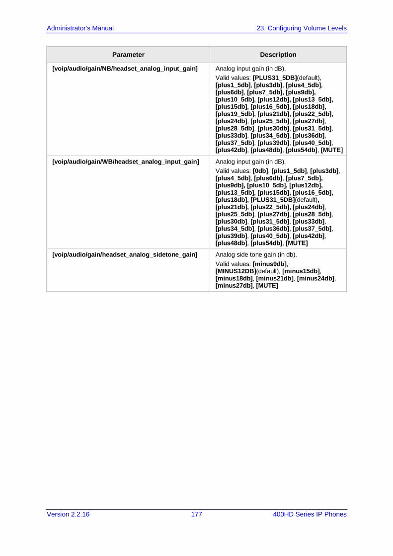
Administrator's Manual 23. Configuring Volume Levels
Version 2.2.16 177 400HD Series IP Phones
Parameter Description
[voip/audio/gain/NB/headset_analog_input_gain] Analog input gain (in dB). Valid values: [PLUS31_5DB](default), [plus1_5db], [plus3db], [plus4_5db], [plus6db], [plus7_5db], [plus9db], [plus10_5db], [plus12db], [plus13_5db], [plus15db], [plus16_5db], [plus18db], [plus19_5db], [plus21db], [plus22_5db], [plus24db], [plus25_5db], [plus27db], [plus28_5db], [plus30db], [plus31_5db], [plus33db], [plus34_5db], [plus36db], [plus37_5db], [plus39db], [plus40_5db], [plus42db], [plus48db], [plus54db], [MUTE]
[voip/audio/gain/WB/headset_analog_input_gain] Analog input gain (in dB). Valid values: [0db], [plus1_5db], [plus3db], [plus4_5db], [plus6db], [plus7_5db], [plus9db], [plus10_5db], [plus12db], [plus13_5db], [plus15db], [plus16_5db], [plus18db], [PLUS31_5DB](default), [plus21db], [plus22_5db], [plus24db], [plus25_5db], [plus27db], [plus28_5db], [plus30db], [plus31_5db], [plus33db], [plus34_5db], [plus36db], [plus37_5db], [plus39db], [plus40_5db], [plus42db], [plus48db], [plus54db], [MUTE]
[voip/audio/gain/headset_analog_sidetone_gain] Analog side tone gain (in db). Valid values: [minus9db], [MINUS12DB](default), [minus15db], [minus18db], [minus21db], [minus24db], [minus27db], [MUTE]

400HD Series IP Phones
Administrator's Manual 178 Document #: LTRT-11957
This page is intentionally left blank.
Part VI Advanced Phone Settings

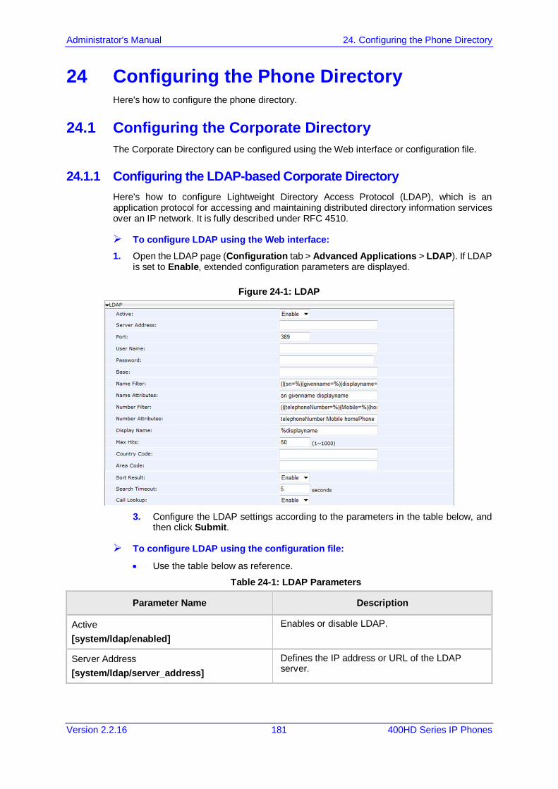
Administrator's Manual 24. Configuring the Phone Directory
Version 2.2.16 181 400HD Series IP Phones
24 Configuring the Phone Directory Here's how to configure the phone directory.
24.1 Configuring the Corporate Directory The Corporate Directory can be configured using the Web interface or configuration file.
24.1.1 Configuring the LDAP-based Corporate Directory Here's how to configure Lightweight Directory Access Protocol (LDAP), which is an application protocol for accessing and maintaining distributed directory information services over an IP network. It is fully described under RFC 4510.
To configure LDAP using the Web interface: 1. Open the LDAP page (Configuration tab > Advanced Applications > LDAP). If LDAP
is set to Enable, extended configuration parameters are displayed.
Figure 24-1: LDAP
3. Configure the LDAP settings according to the parameters in the table below, and
then click Submit.
To configure LDAP using the configuration file:
• Use the table below as reference.
Table 24-1: LDAP Parameters
Parameter Name Description
Active [system/ldap/enabled]
Enables or disable LDAP.
Server Address [system/ldap/server_address]
Defines the IP address or URL of the LDAP server.

400HD Series IP Phones
Administrator's Manual 182 Document #: LTRT-11957
Parameter Name Description
Port [system/ldap/port]
Defines the LDAP service port.
User Name [system/ldap/user_name]
Defines the user name used for the LDAP search request.
Password [system/ldap/password]
Defines the password of the search requester.
Base [system/ldap/base]
Defines the access point on the LDAP tree.
Name Filter [system/ldap/name_filter]
Specifies your search pattern for name look ups. For example: When you type in the following field: (&(telephoneNumber=*)(sn=%)), the search result includes all LDAP records, which have the 'telephoneNumber' field set and the '(“sn”-->surname)' field starting with the entered prefix. When you type in the following field: (|(cn=%)(sn=%)), the search result includes all LDAP records which have the '(“cn”-->CommonName)' OR '(“sn”-->Surname)' field starting with the entered prefix. When you type in the following field: (!(cn=%)), the search result includes all LDAP records which “do not” have the “cn” field starting with the entered prefix.
Name Attribute [system/ldap/name_attrs]
Specifies the LDAP name attributes setting, which can be used to specify the “name” attributes of each record which is returned in the LDAP search results. When you type in the following field, for example, cn sn displayName”, this requires you to specify 'cn-->commonName'. This is the Full name of the user, sn-->Surname, last name or family name and “displayName” fields for each LDAP record.
Number Filter [system/ldap/number_filter]
Specifies your search pattern for number look ups. When you type in the following field, for example, (|(telephoneNumber=%)(Mobile=%)(ipPhone=%)), the search result is all LDAP records which have the “telephoneNumber” OR “Mobile” OR “ipPhone”field match the number being searched. When you type in the following field: (&(telephoneNumber=%)(sn=*)), the search result is all LDAP records which have the “sn” field set and the “telephoneNumber” match the number being searched.
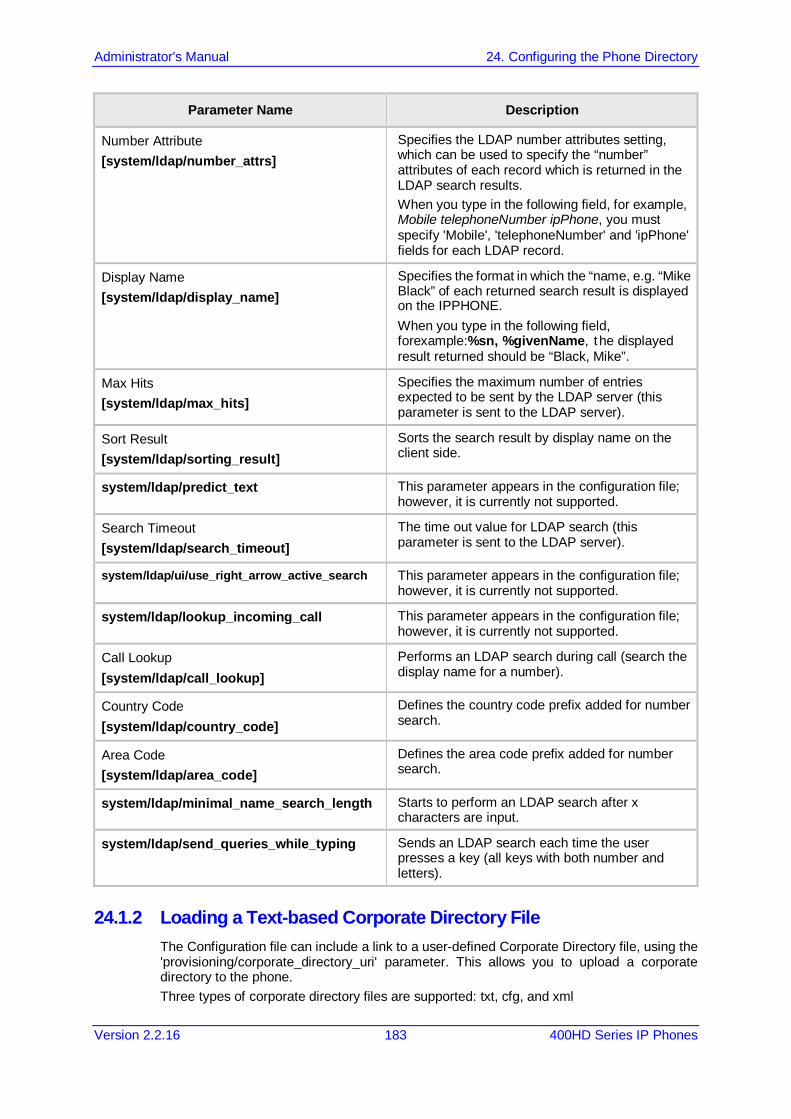
Administrator's Manual 24. Configuring the Phone Directory
Version 2.2.16 183 400HD Series IP Phones
Parameter Name Description
Number Attribute [system/ldap/number_attrs]
Specifies the LDAP number attributes setting, which can be used to specify the “number” attributes of each record which is returned in the LDAP search results. When you type in the following field, for example, Mobile telephoneNumber ipPhone, you must specify 'Mobile', 'telephoneNumber' and 'ipPhone' fields for each LDAP record.
Display Name [system/ldap/display_name]
Specifies the format in which the “name, e.g. “Mike Black” of each returned search result is displayed on the IPPHONE. When you type in the following field, forexample:%sn, %givenName, the displayed result returned should be “Black, Mike”.
Max Hits [system/ldap/max_hits]
Specifies the maximum number of entries expected to be sent by the LDAP server (this parameter is sent to the LDAP server).
Sort Result [system/ldap/sorting_result]
Sorts the search result by display name on the client side.
system/ldap/predict_text This parameter appears in the configuration file; however, it is currently not supported.
Search Timeout [system/ldap/search_timeout]
The time out value for LDAP search (this parameter is sent to the LDAP server).
system/ldap/ui/use_right_arrow_active_search This parameter appears in the configuration file; however, it is currently not supported.
system/ldap/lookup_incoming_call This parameter appears in the configuration file; however, it is currently not supported.
Call Lookup [system/ldap/call_lookup]
Performs an LDAP search during call (search the display name for a number).
Country Code [system/ldap/country_code]
Defines the country code prefix added for number search.
Area Code [system/ldap/area_code]
Defines the area code prefix added for number search.
system/ldap/minimal_name_search_length Starts to perform an LDAP search after x characters are input.
system/ldap/send_queries_while_typing Sends an LDAP search each time the user presses a key (all keys with both number and letters).
24.1.2 Loading a Text-based Corporate Directory File The Configuration file can include a link to a user-defined Corporate Directory file, using the 'provisioning/corporate_directory_uri' parameter. This allows you to upload a corporate directory to the phone. Three types of corporate directory files are supported: txt, cfg, and xml
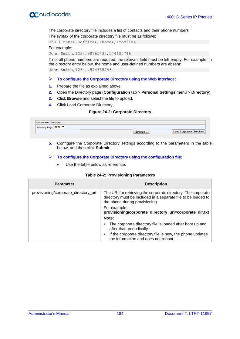
400HD Series IP Phones
Administrator's Manual 184 Document #: LTRT-11957
The corporate directory file includes a list of contacts and their phone numbers. The syntax of the corporate directory file must be as follows: <full name>,<office>,<home>,<mobile>
For example: John Smith,1234,98765432,574685746
If not all phone numbers are required, the relevant field must be left empty. For example, in the directory entry below, the home and user-defined numbers are absent: John Smith,1234,,574685746
To configure the Corporate Directory using the Web interface: 1. Prepare the file as explained above. 2. Open the Directory page (Configuration tab > Personal Settings menu > Directory). 3. Click Browse and select the file to upload. 4. Click Load Corporate Directory.
Figure 24-2: Corporate Directory
5. Configure the Corporate Directory settings according to the parameters in the table
below, and then click Submit.
To configure the Corporate Directory using the configuration file:
• Use the table below as reference.
Table 24-2: Provisioning Parameters
Parameter Description
provisioning/corporate_directory_uri The URI for retrieving the corporate directory. The corporate directory must be included in a separate file to be loaded to the phone during provisioning. For example: provisioning/corporate_directory_uri=corporate_dir.txt Note: The corporate directory file is loaded after boot up and
after that, periodically. If the corporate directory file is new, the phone updates
the information and does not reboot.

Administrator's Manual 24. Configuring the Phone Directory
Version 2.2.16 185 400HD Series IP Phones
24.2 Modifying the Local Phone Directory You can add, edit, or delete directory contacts. A contact's address can be a telephone number, IP address, or domain name. You can also download or upload a personal directory file through the Web interface.
To add a contact to the phone's directory: 1. Open the Directory page (Configuration tab > Personal Settings menu > Directory).
Figure 24-3: Directory - Add Contact
2. Under the Add Contact group, define the contact: 3. In the 'Name' field, enter the name of the contact. 4. In the 'Office', 'Home' and/or 'Mobile' fields, enter the contact's telephone numbers. The
contact's number can be defined with an IP address or domain name (e.g. <number>@<IP address or domain name>).
5. Click Submit; the contact appears in the Directory list at the bottom of the page.
To edit a contact: 1. If the contact does not appear in the displayed Directory list, then from the 'Directory
Page' drop-down list, select the page in the directory that you want displayed. 2. In the Directory list, click the number that appears in the 'No.' column corresponding to
the contact you want to edit; the contact's attributes appear in the Edit Phone group above.
3. Edit the contact as required, and then click Submit; the contact's new attributes are updated in the Directory list.
To delete a contact: 1. In the Directory list, mark the 'Select' check box corresponding to the contact you want
to delete. 2. Click Delete. (To delete all contacts, click the Delete All button).

400HD Series IP Phones
Administrator's Manual 186 Document #: LTRT-11957
This page is intentionally left blank.
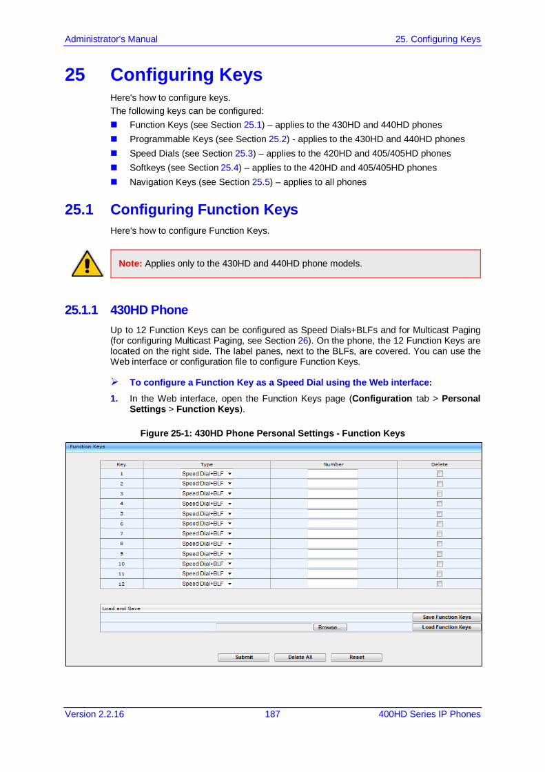
Administrator's Manual 25. Configuring Keys
Version 2.2.16 187 400HD Series IP Phones
25 Configuring Keys Here's how to configure keys. The following keys can be configured: Function Keys (see Section 25.1) – applies to the 430HD and 440HD phones Programmable Keys (see Section 25.2) - applies to the 430HD and 440HD phones Speed Dials (see Section 25.3) – applies to the 420HD and 405/405HD phones Softkeys (see Section 25.4) – applies to the 420HD and 405/405HD phones Navigation Keys (see Section 25.5) – applies to all phones
25.1 Configuring Function Keys Here's how to configure Function Keys.
Note: Applies only to the 430HD and 440HD phone models.
25.1.1 430HD Phone Up to 12 Function Keys can be configured as Speed Dials+BLFs and for Multicast Paging (for configuring Multicast Paging, see Section 26). On the phone, the 12 Function Keys are located on the right side. The label panes, next to the BLFs, are covered. You can use the Web interface or configuration file to configure Function Keys.
To configure a Function Key as a Speed Dial using the Web interface: 1. In the Web interface, open the Function Keys page (Configuration tab > Personal
Settings > Function Keys).
Figure 25-1: 430HD Phone Personal Settings - Function Keys
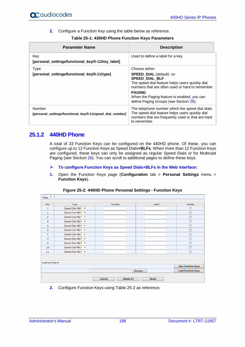
400HD Series IP Phones
Administrator's Manual 188 Document #: LTRT-11957
2. Configure a Function Key using the table below as reference.
Table 25-1: 430HD Phone Function Keys Parameters
Parameter Name Description
Key [personal_settings/functional_key/0-11/key_label]
Used to define a label for a key.
Type [personal_settings/functional_key/0-11/type]
Choose either: SPEED_DIAL (default) -or- SPEED_DIAL_BLF The speed-dial feature helps users quickly dial numbers that are often used or hard to remember. PAGING When the Paging feature is enabled, you can define Paging Groups (see Section 26).
Number [personal_settings/functional_key/0-11/speed_dial_number]
The telephone number which the speed dial dials. The speed-dial feature helps users quickly dial numbers that are frequently used or that are hard to remember.
25.1.2 440HD Phone A total of 33 Function Keys can be configured on the 440HD phone. Of these, you can configure up to 12 Function Keys as Speed Dials+BLFs. When more than 12 Function Keys are configured, these keys can only be assigned as regular Speed Dials or for Multicast Paging (see Section 26). You can scroll to additional pages to define these keys.
To configure Function Keys as Speed Dials+BLFs in the Web interface: 1. Open the Function Keys page (Configuration tab > Personal Settings menu >
Function Keys).
Figure 25-2: 440HD Phone Personal Settings - Function Keys
2. Configure Function Keys using Table 25-2 as reference.
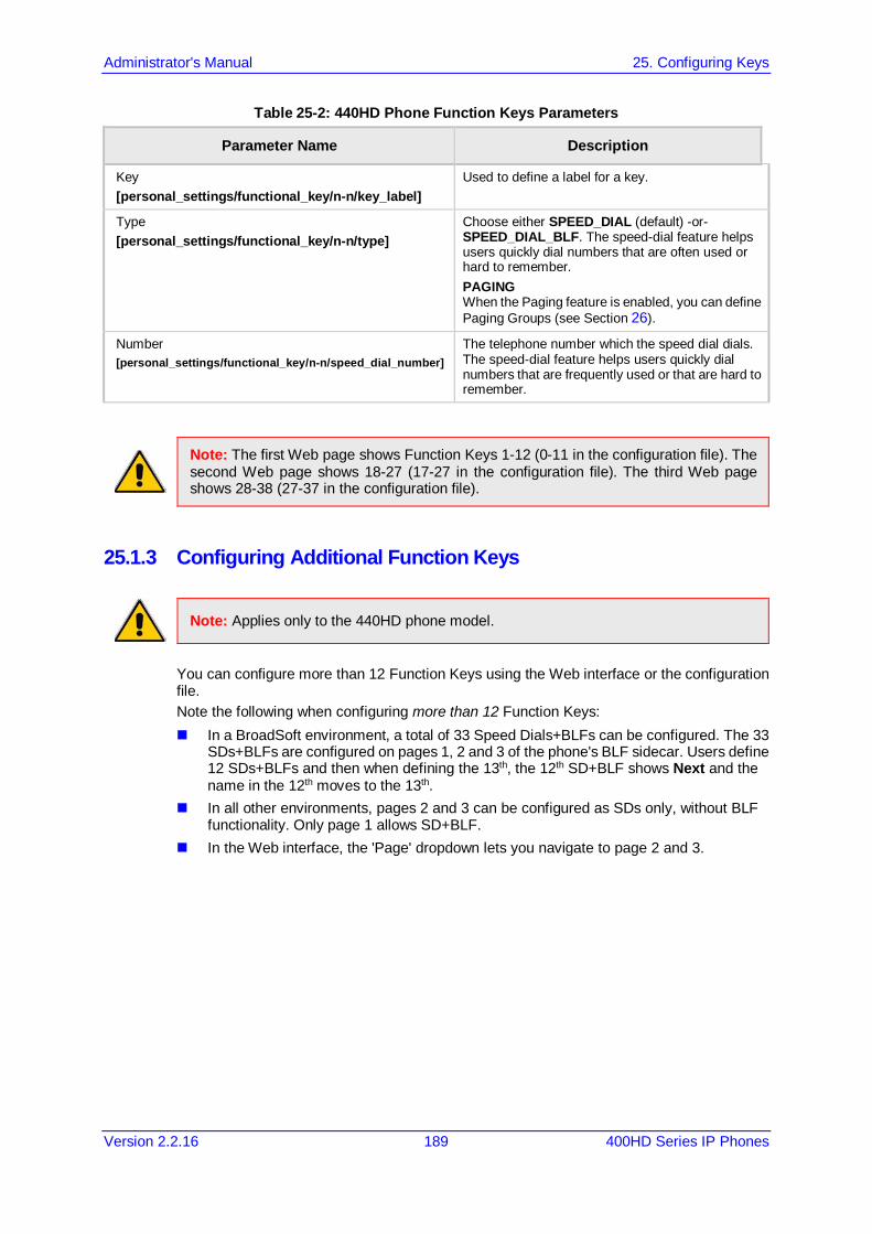
Administrator's Manual 25. Configuring Keys
Version 2.2.16 189 400HD Series IP Phones
Table 25-2: 440HD Phone Function Keys Parameters
Parameter Name Description
Key [personal_settings/functional_key/n-n/key_label]
Used to define a label for a key.
Type [personal_settings/functional_key/n-n/type]
Choose either SPEED_DIAL (default) -or- SPEED_DIAL_BLF. The speed-dial feature helps users quickly dial numbers that are often used or hard to remember. PAGING When the Paging feature is enabled, you can define Paging Groups (see Section 26).
Number [personal_settings/functional_key/n-n/speed_dial_number]
The telephone number which the speed dial dials. The speed-dial feature helps users quickly dial numbers that are frequently used or that are hard to remember.
Note: The first Web page shows Function Keys 1-12 (0-11 in the configuration file). The second Web page shows 18-27 (17-27 in the configuration file). The third Web page shows 28-38 (27-37 in the configuration file).
25.1.3 Configuring Additional Function Keys
Note: Applies only to the 440HD phone model.
You can configure more than 12 Function Keys using the Web interface or the configuration file. Note the following when configuring more than 12 Function Keys: In a BroadSoft environment, a total of 33 Speed Dials+BLFs can be configured. The 33
SDs+BLFs are configured on pages 1, 2 and 3 of the phone's BLF sidecar. Users define 12 SDs+BLFs and then when defining the 13th, the 12th SD+BLF shows Next and the name in the 12th moves to the 13th.
In all other environments, pages 2 and 3 can be configured as SDs only, without BLF functionality. Only page 1 allows SD+BLF.
In the Web interface, the 'Page' dropdown lets you navigate to page 2 and 3.
400HD Series IP Phones
Administrator's Manual 190 Document #: LTRT-11957
25.2 Configuring Programmable Keys
Note: Applies to the 430HD and 440HD phone models.
25.2.1 430HD and 440HD Phones Six programmable keys are located adjacent to the screen. There are three on each side. They're labeled 1-6 in the Web interface and 12-17 in the configuration file. You can configure them as Extension lines (SIP accounts) (see the next section) Speed Dials / Speed Dials+BLFs (see Section 25.2.1.1) Key Events such as MISSED_CALLS (see Section 25.2.1.2)
To access the Programmable Keys in the Web interface: 1. Open the Programmable Keys page (Configuration tab > Personal Settings menu >
Programmable Keys).
Figure 25-3: Programmable Keys (430HD/440HD Phones)
2. Use the table below as reference when configuring the 430HD/440HD phones.
Table 25-3: Programmable Keys Parameters (430HD/440HD Phones)
Parameter Name Description
Line Key Select 1-6. Network administrators can configure these six Programmable Keys; see the next parameter 'Key Type'. The keys are located on either side of the screen, three on either side. The uppermost left is 1; the lowermost right is 6. Users are disabled from configuring them as Line Keys (SIP Accounts). The first two are by default set to lines. The other four are by default empty.
Key Type The six Programmable Keys can be configured as: SIP Account (Extension Line) SPEED DIAL SPEED DIAL+BLF Key Event
Key Label Enter a Label for the key reflecting the event, for example, enter Dialed in the 'Key Label' field if you're programming a Dialed Calls Key Event. The label will appear in the screen.
Paging Group Name The name of the Paging Group. All phone extensions assigned to this group are paged when a message is multicast from an extension in the group.
Paging Multicast The IP address via which multicast messages traverse. When a user
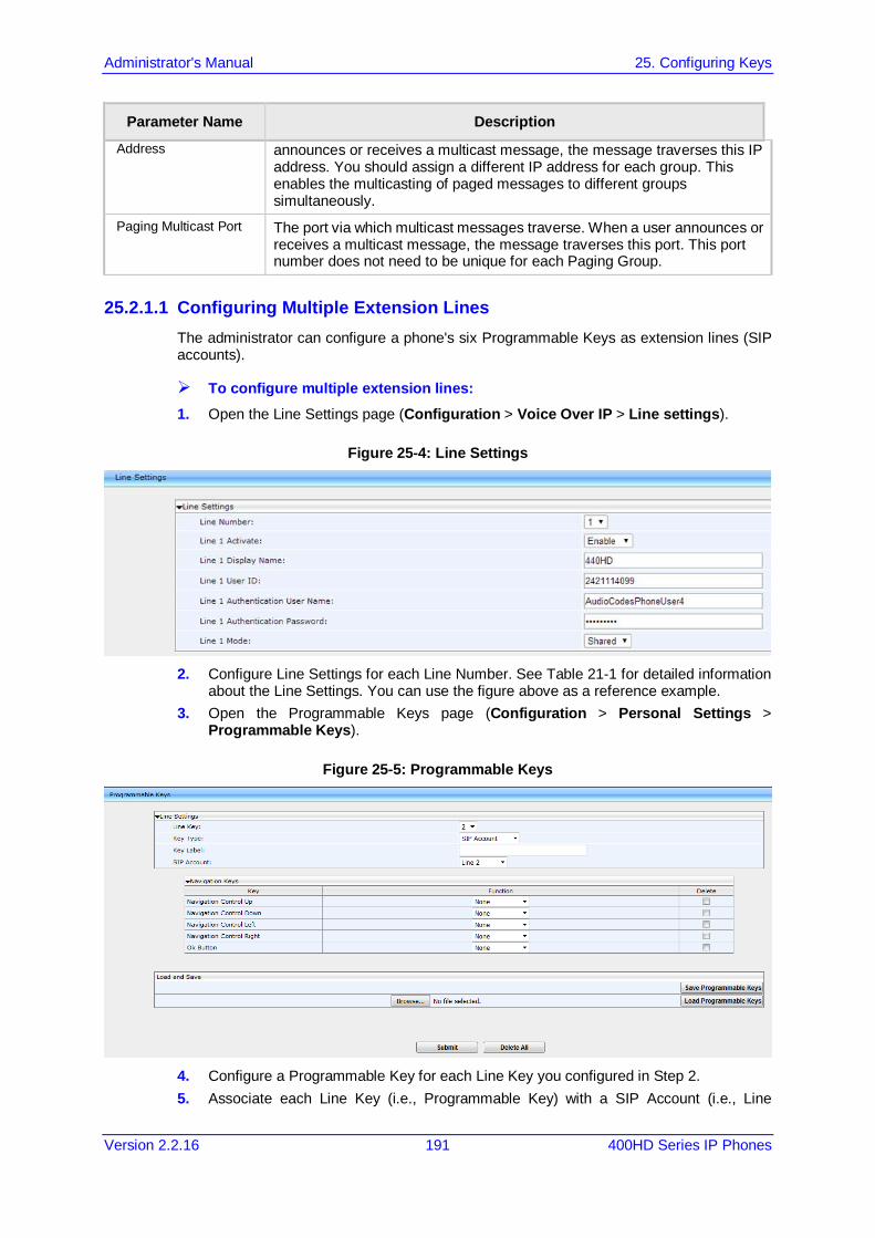
Administrator's Manual 25. Configuring Keys
Version 2.2.16 191 400HD Series IP Phones
Parameter Name Description Address announces or receives a multicast message, the message traverses this IP
address. You should assign a different IP address for each group. This enables the multicasting of paged messages to different groups simultaneously.
Paging Multicast Port The port via which multicast messages traverse. When a user announces or receives a multicast message, the message traverses this port. This port number does not need to be unique for each Paging Group.
25.2.1.1 Configuring Multiple Extension Lines The administrator can configure a phone's six Programmable Keys as extension lines (SIP accounts).
To configure multiple extension lines: 1. Open the Line Settings page (Configuration > Voice Over IP > Line settings).
Figure 25-4: Line Settings
2. Configure Line Settings for each Line Number. See Table 21-1 for detailed information
about the Line Settings. You can use the figure above as a reference example. 3. Open the Programmable Keys page (Configuration > Personal Settings >
Programmable Keys).
Figure 25-5: Programmable Keys
4. Configure a Programmable Key for each Line Key you configured in Step 2. 5. Associate each Line Key (i.e., Programmable Key) with a SIP Account (i.e., Line

400HD Series IP Phones
Administrator's Manual 192 Document #: LTRT-11957
Number). You can alternatively perform the association using the configuration file. Use the table below as reference:
Table 25-4: Associating Line Keys with SIP Accounts using the configuration file
Parameter Name Description
[voip/line_key/0/line] Default: 0. Indicates that this is the first Programmable Key, located in the upper left corner of the screen. Leave the setting at its default.
[voip/line_key/1/line] Default: 0. Indicates that the second Programmable Key is assigned to line 0 by default. Change it to 1 to assign the Programmable Key to line 1.
[voip/line_key/2-5/line] Defaults: 2-5. Indicates the third through to the sixth Programmable Key.
[personal_settings/functional_key/12-17/key_label]
These are the labels displayed in the screen next to Programmable Keys 0-5. Define the string of characters you want displayed (name, extension, etc.).
[personal_settings/functional_key/12-17/type]
Default: SIP_ACCOUNT. Can be set to perform other functions such as Speed Dial or Key Event. Do not change these for keys you want to assign to SIP lines.
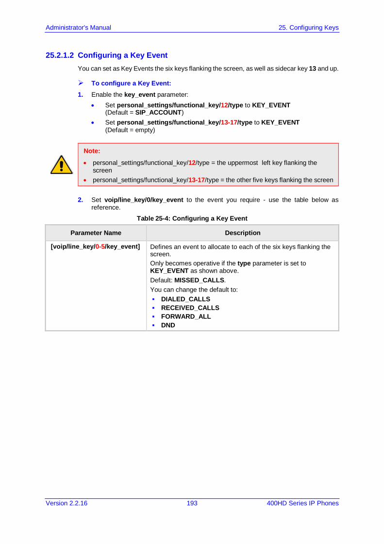
Administrator's Manual 25. Configuring Keys
Version 2.2.16 193 400HD Series IP Phones
25.2.1.2 Configuring a Key Event You can set as Key Events the six keys flanking the screen, as well as sidecar key 13 and up.
To configure a Key Event: 1. Enable the key_event parameter:
• Set personal_settings/functional_key/12/type to KEY_EVENT (Default = SIP_ACCOUNT)
• Set personal_settings/functional_key/13-17/type to KEY_EVENT (Default = empty)
Note:
• personal_settings/functional_key/12/type = the uppermost left key flanking the screen
• personal_settings/functional_key/13-17/type = the other five keys flanking the screen
2. Set voip/line_key/0/key_event to the event you require - use the table below as reference.
Table 25-4: Configuring a Key Event
Parameter Name Description
[voip/line_key/0-5/key_event] Defines an event to allocate to each of the six keys flanking the screen. Only becomes operative if the type parameter is set to KEY_EVENT as shown above. Default: MISSED_CALLS. You can change the default to: DIALED_CALLS RECEIVED_CALLS FORWARD_ALL DND
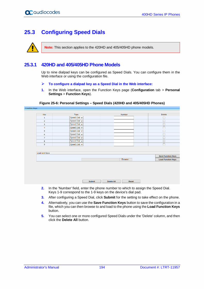
400HD Series IP Phones
Administrator's Manual 194 Document #: LTRT-11957
25.3 Configuring Speed Dials
Note: This section applies to the 420HD and 405/405HD phone models.
25.3.1 420HD and 405/405HD Phone Models Up to nine dialpad keys can be configured as Speed Dials. You can configure them in the Web interface or using the configuration file.
To configure a dialpad key as a Speed Dial in the Web interface: 1. In the Web interface, open the Function Keys page (Configuration tab > Personal
Settings > Function Keys).
Figure 25-6: Personal Settings – Speed Dials (420HD and 405/405HD Phones)
2. In the 'Number' field, enter the phone number to which to assign the Speed Dial.
Keys 1-9 correspond to the 1-9 keys on the device's dial pad. 3. After configuring a Speed Dial, click Submit for the setting to take effect on the phone. 4. Alternatively, you can use the Save Function Keys button to save the configuration in a
file, which you can then browse to and load to the phone using the Load Function Keys button.
5. You can select one or more configured Speed Dials under the 'Delete' column, and then click the Delete All button.
Administrator's Manual 25. Configuring Keys
Version 2.2.16 195 400HD Series IP Phones
To configure a key as a Speed Dial using the configuration file: Open the Configuration File page (Management tab > Manual Update >
Configuration File) and locate the Function Key parameters. Use the table below as reference when configuring the parameters.
Table 25-5: Speed Dials Parameters
Parameter Name Description
[personal_settings/functional_key/0-8/speed_dial_extension] Used to define a label for a Speed Dial.
[personal_settings/functional_key/0/speed_dial_number] The telephone number which the speed dial dials. The speed-dial feature helps users quickly dial numbers that are frequently used or that are hard to remember.
[personal_settings/functional_key/0/type=SPEED_DIAL] The feature helps users quickly dial numbers that are often used or that are hard to remember.
25.3.2 Deleting Speed Dials You can delete configured Speed Dials.
To delete Speed Dials:
• Check the 'Delete' box corresponding to the Speed Dial that you want to delete, and then click Submit -or-
• Click the Delete All button, and then at the prompt, click OK
To clear (unselect) all selected 'Delete' check boxes:
• Click the Reset button.
25.3.3 Saving Configured Speed Dials After configuring Speed Dials in the Web interface, you can save the configuration in a cfg file on your computer and then load it to other phones.
To save Speed Dials in a cfg file: 1. Open the Function Keys page (Configuration tab > Personal Settings menu >
Function Keys). 2. Click Save Function Keys; the configuration is saved in a .cfg file.
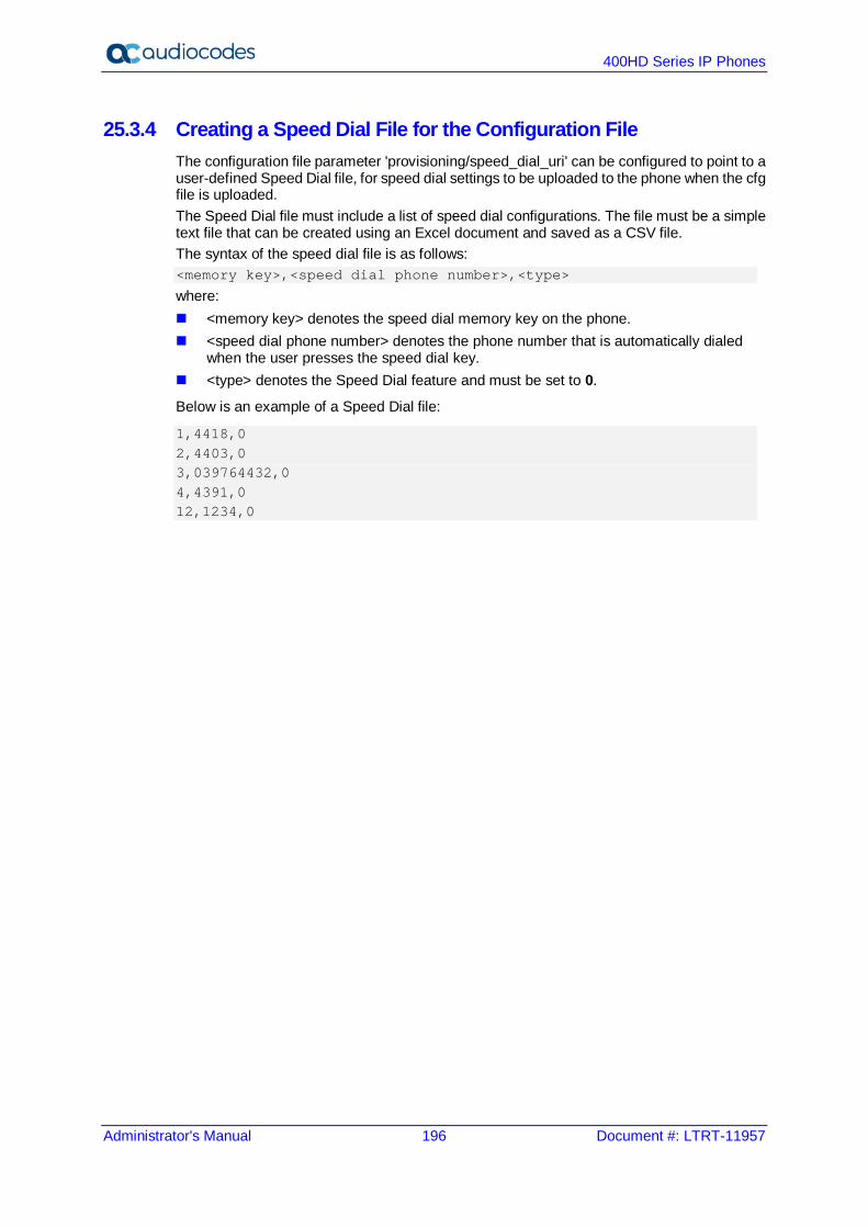
400HD Series IP Phones
Administrator's Manual 196 Document #: LTRT-11957
25.3.4 Creating a Speed Dial File for the Configuration File The configuration file parameter 'provisioning/speed_dial_uri' can be configured to point to a user-defined Speed Dial file, for speed dial settings to be uploaded to the phone when the cfg file is uploaded. The Speed Dial file must include a list of speed dial configurations. The file must be a simple text file that can be created using an Excel document and saved as a CSV file. The syntax of the speed dial file is as follows: <memory key>,<speed dial phone number>,<type>
where: <memory key> denotes the speed dial memory key on the phone. <speed dial phone number> denotes the phone number that is automatically dialed
when the user presses the speed dial key. <type> denotes the Speed Dial feature and must be set to 0.
Below is an example of a Speed Dial file:
1,4418,0 2,4403,0 3,039764432,0 4,4391,0 12,1234,0

Administrator's Manual 25. Configuring Keys
Version 2.2.16 197 400HD Series IP Phones
25.4 Configuring Softkeys
Note:
• The section applies to the 420HD and 405/405HD phone models. • When Genesys’ ACD is enabled, the Soft Keys item in the Keys Configuration menu
is not displayed.
This section describes how to configure softkeys. Four softkeys, located below the screen, can be configured. Their functionality is context sensitive according to the phone's state. Here's how to configure softkeys that are activated when the phone is in idle state and when it is in call state. Following are the four default (preconfigured) softkeys (0-3), when the phone is in idle state and when it is in call state.
Table 25-6: Default Softkeys
Key Idle State Call State
0 Directory Hold
1 Missed Conf
2 Forward New Call
3 Do Not Disturb (Status) End
When more than four softkeys are configured, users can scroll to additional pages, where on each configured page, the fourth key becomes the More softkey. Up to 20 (0-19) softkey functions can be configured for when the phone is in idle call
state. Up to 20 (0-19) softkey functions can be configured for when the phone is in call state. Up to 12 (0-11) programmable softkey (PSKs) functions can be configured to either a
call state softkey or an idle state softkey.
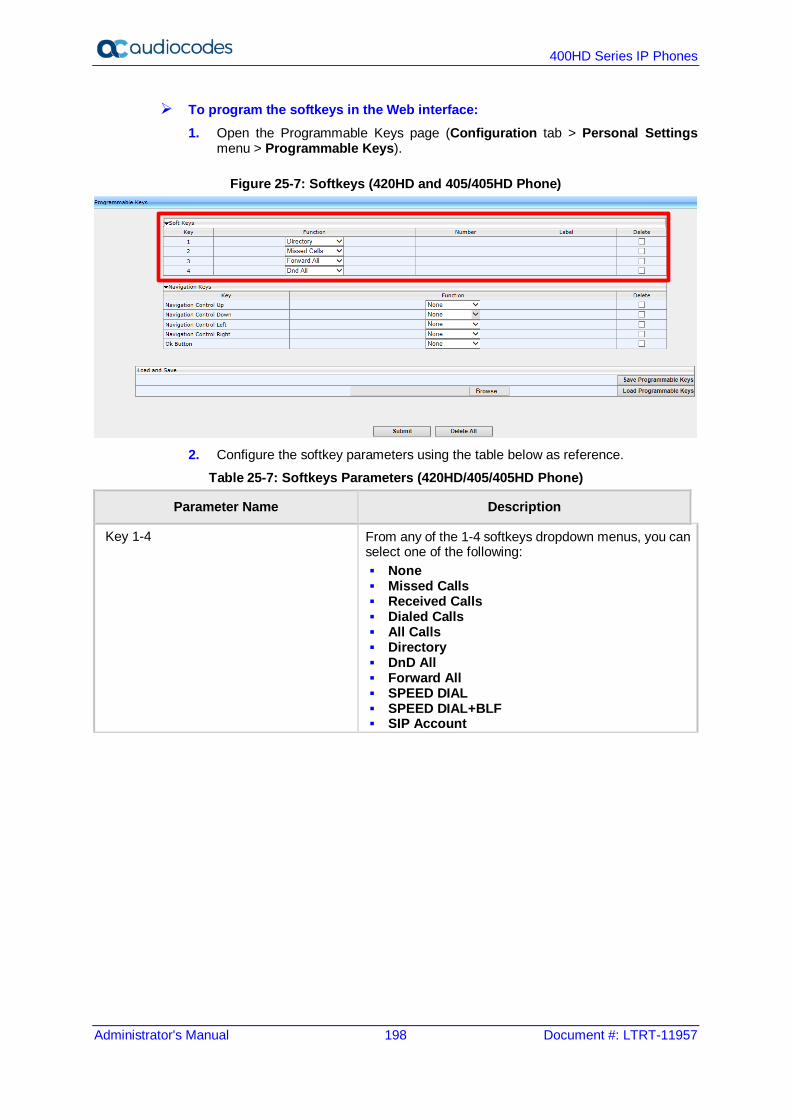
400HD Series IP Phones
Administrator's Manual 198 Document #: LTRT-11957
To program the softkeys in the Web interface: 1. Open the Programmable Keys page (Configuration tab > Personal Settings
menu > Programmable Keys).
Figure 25-7: Softkeys (420HD and 405/405HD Phone)
2. Configure the softkey parameters using the table below as reference.
Table 25-7: Softkeys Parameters (420HD/405/405HD Phone)
Parameter Name Description
Key 1-4 From any of the 1-4 softkeys dropdown menus, you can select one of the following: None Missed Calls Received Calls Dialed Calls All Calls Directory DnD All Forward All SPEED DIAL SPEED DIAL+BLF SIP Account
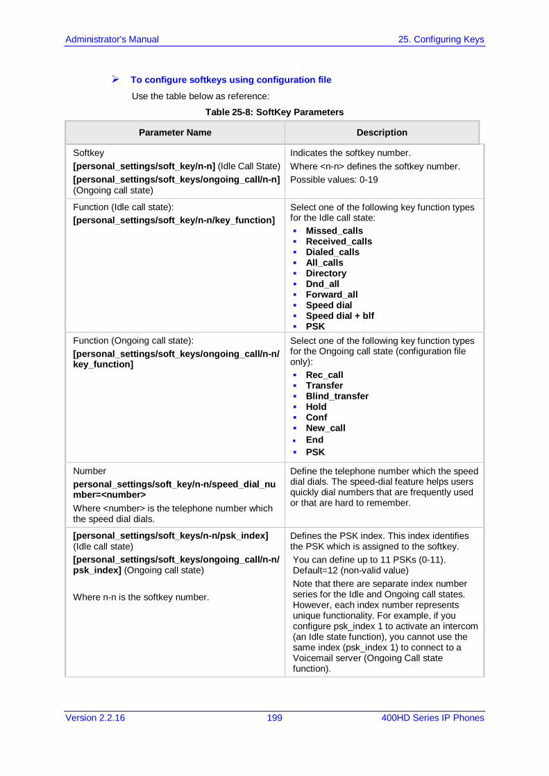
Administrator's Manual 25. Configuring Keys
Version 2.2.16 199 400HD Series IP Phones
To configure softkeys using configuration file Use the table below as reference:
Table 25-8: SoftKey Parameters
Parameter Name Description
Softkey [personal_settings/soft_key/n-n] (Idle Call State) [personal_settings/soft_keys/ongoing_call/n-n] (Ongoing call state)
Indicates the softkey number. Where <n-n> defines the softkey number. Possible values: 0-19
Function (Idle call state): [personal_settings/soft_key/n-n/key_function]
Select one of the following key function types for the Idle call state: Missed_calls Received_calls Dialed_calls All_calls Directory Dnd_all Forward_all Speed dial Speed dial + blf PSK
Function (Ongoing call state): [personal_settings/soft_keys/ongoing_call/n-n/key_function]
Select one of the following key function types for the Ongoing call state (configuration file only): Rec_call Transfer Blind_transfer Hold Conf New_call • End PSK
Number personal_settings/soft_key/n-n/speed_dial_number=<number> Where <number> is the telephone number which the speed dial dials.
Define the telephone number which the speed dial dials. The speed-dial feature helps users quickly dial numbers that are frequently used or that are hard to remember.
[personal_settings/soft_keys/n-n/psk_index] (Idle call state) [personal_settings/soft_keys/ongoing_call/n-n/psk_index] (Ongoing call state) Where n-n is the softkey number.
Defines the PSK index. This index identifies the PSK which is assigned to the softkey. You can define up to 11 PSKs (0-11). Default=12 (non-valid value) Note that there are separate index number series for the Idle and Ongoing call states. However, each index number represents unique functionality. For example, if you configure psk_index 1 to activate an intercom (an Idle state function), you cannot use the same index (psk_index 1) to connect to a Voicemail server (Ongoing Call state function).
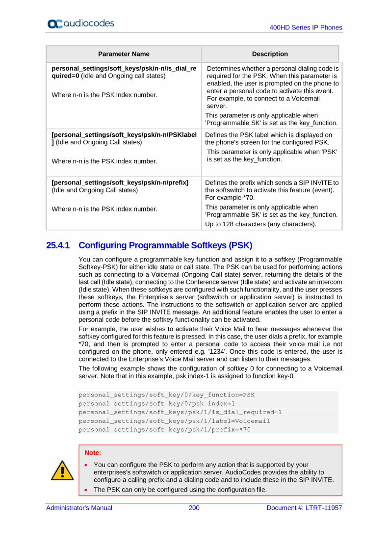
400HD Series IP Phones
Administrator's Manual 200 Document #: LTRT-11957
Parameter Name Description
personal_settings/soft_keys/psk/n-n/is_dial_required=0 (Idle and Ongoing call states) Where n-n is the PSK index number.
Determines whether a personal dialing code is required for the PSK. When this parameter is enabled, the user is prompted on the phone to enter a personal code to activate this event. For example, to connect to a Voicemail server.
This parameter is only applicable when 'Programmable SK' is set as the key_function.
[personal_settings/soft_keys/psk/n-n/PSKlabel] (Idle and Ongoing Call states) Where n-n is the PSK index number.
Defines the PSK label which is displayed on the phone's screen for the configured PSK. This parameter is only applicable when 'PSK' is set as the key_function.
[personal_settings/soft_keys/psk/n-n/prefix] (Idle and Ongoing Call states) Where n-n is the PSK index number.
Defines the prefix which sends a SIP INVITE to the softswitch to activate this feature (event). For example *70. This parameter is only applicable when 'Programmable SK' is set as the key_function. Up to 128 characters (any characters).
25.4.1 Configuring Programmable Softkeys (PSK) You can configure a programmable key function and assign it to a softkey (Programmable Softkey-PSK) for either idle state or call state. The PSK can be used for performing actions such as connecting to a Voicemail (Ongoing Call state) server, returning the details of the last call (Idle state), connecting to the Conference server (Idle state) and activate an intercom (Idle state). When these softkeys are configured with such functionality, and the user presses these softkeys, the Enterprise's server (softswitch or application server) is instructed to perform these actions. The instructions to the softswitch or application server are applied using a prefix in the SIP INVITE message. An additional feature enables the user to enter a personal code before the softkey functionality can be activated. For example, the user wishes to activate their Voice Mail to hear messages whenever the softkey configured for this feature is pressed. In this case, the user dials a prefix, for example *70, and then is prompted to enter a personal code to access their voice mail i.e not configured on the phone, only entered e.g. '1234'. Once this code is entered, the user is connected to the Enterprise's Voice Mail server and can listen to their messages. The following example shows the configuration of softkey 0 for connecting to a Voicemail server. Note that in this example, psk index-1 is assigned to function key-0. personal_settings/soft_key/0/key_function=PSK personal_settings/soft_key/0/psk_index=1 personal_settings/soft_keys/psk/1/is_dial_required=1 personal_settings/soft_keys/psk/1/label=Voicemail personal_settings/soft_keys/psk/1/prefix=*70
Note:
• You can configure the PSK to perform any action that is supported by your enterprises's softswitch or application server. AudioCodes provides the ability to configure a calling prefix and a dialing code and to include these in the SIP INVITE.
• The PSK can only be configured using the configuration file.

Administrator's Manual 25. Configuring Keys
Version 2.2.16 201 400HD Series IP Phones
25.5 Configuring Navigation Control Button Positions
Note: This section applies to all phone models.
Each of the four positions of the navigation control button on the phone, i.e., Up, Down, Left, and Right, as well as its OK button, can be configured to perform a one of five functions: None (default) Missed Calls Received Calls Dialed Calls All Calls Directory For example, from the 'Navigation Control Up' key dropdown in the Navigation Keys section of the page (see the figure below), select Missed Calls, and then click the Submit button; the user will be able to press the upper rim of the navigation control button on their phone to display the Missed Calls on the phone screen. The OK button can also be configured to perform one of these five functions. A Delete option adjacent to each Navigation Control key and adjacent to 'Ok Button' can be selected to remove the function from the key/button.
To configure navigation control button positions in the Web interface: 1. Open the Programmable Keys page (Configuration tab > Personal Settings
menu > Programmable Keys) and locate the Navigation Keys section.
Figure 25-8: Navigation Keys
2. From the 'Navigation Control Up' key dropdown, select (for example) Missed
Calls, and then click the Submit button; the user will be able to press the upper rim of the navigation control button on their phone to display the Missed Calls in the phone screen.
3. [Optionally] Select the Delete option next to to a key to remove the function.
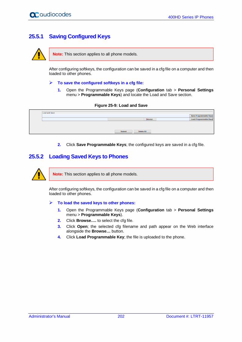
400HD Series IP Phones
Administrator's Manual 202 Document #: LTRT-11957
25.5.1 Saving Configured Keys
Note: This section applies to all phone models.
After configuring softkeys, the configuration can be saved in a cfg file on a computer and then loaded to other phones.
To save the configured softkeys in a cfg file: 1. Open the Programmable Keys page (Configuration tab > Personal Settings
menu > Programmable Keys) and locate the Load and Save section.
Figure 25-9: Load and Save
2. Click Save Programmable Keys; the configured keys are saved in a cfg file.
25.5.2 Loading Saved Keys to Phones
Note: This section applies to all phone models.
After configuring softkeys, the configuration can be saved in a cfg file on a computer and then loaded to other phones.
To load the saved keys to other phones: 1. Open the Programmable Keys page (Configuration tab > Personal Settings
menu > Programmable Keys). 2. Click Browse…. to select the cfg file. 3. Click Open; the selected cfg filename and path appear on the Web interface
alongside the Browse… button. 4. Click Load Programmable Key; the file is uploaded to the phone.
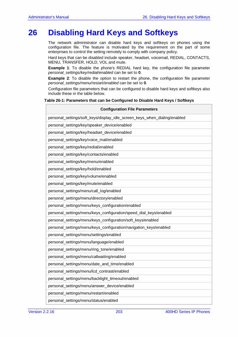
Administrator's Manual 26. Disabling Hard Keys and Softkeys
Version 2.2.16 203 400HD Series IP Phones
26 Disabling Hard Keys and Softkeys The network administrator can disable hard keys and softkeys on phones using the configuration file. The feature is motivated by the requirement on the part of some enterprises to control the setting remotely to comply with company policy. Hard keys that can be disabled include speaker, headset, voicemail, REDIAL, CONTACTS, MENU, TRANSFER, HOLD, VOL and mute. Example 1: To disable the phone's REDIAL hard key, the configuration file parameter personal_settings/key/redial/enabled can be set to 0. Example 2: To disable the option to restart the phone, the configuration file parameter personal_settings/menu/restart/enabled can be set to 0. Configuration file parameters that can be configured to disable hard keys and softkeys also include these in the table below.
Table 26-1: Parameters that can be Configured to Disable Hard Keys / Softkeys
Configuration File Parameters
personal_settings/soft_keys/display_idle_screen_keys_when_dialing/enabled
personal_settings/key/speaker_device/enabled
personal_settings/key/headset_device/enabled
personal_settings/key/voice_mail/enabled
personal_settings/key/redial/enabled
personal_settings/key/contacts/enabled
personal_settings/key/menu/enabled
personal_settings/key/hold/enabled
personal_settings/key/volume/enabled
personal_settings/key/mute/enabled
personal_settings/menu/call_log/enabled
personal_settings/menu/directory/enabled
personal_settings/menu/keys_configuration/enabled
personal_settings/menu/keys_configuration/speed_dial_keys/enabled
personal_settings/menu/keys_configuration/soft_keys/enabled
personal_settings/menu/keys_configuration/navigation_keys/enabled
personal_settings/menu/settings/enabled
personal_settings/menu/language/enabled
personal_settings/menu/ring_tone/enabled
personal_settings/menu/callwaiting/enabled
personal_settings/menu/date_and_time/enabled
personal_settings/menu/lcd_contrast/enabled
personal_settings/menu/backlight_timeout/enabled
personal_settings/menu/answer_device/enabled
personal_settings/menu/restart/enabled
personal_settings/menu/status/enabled
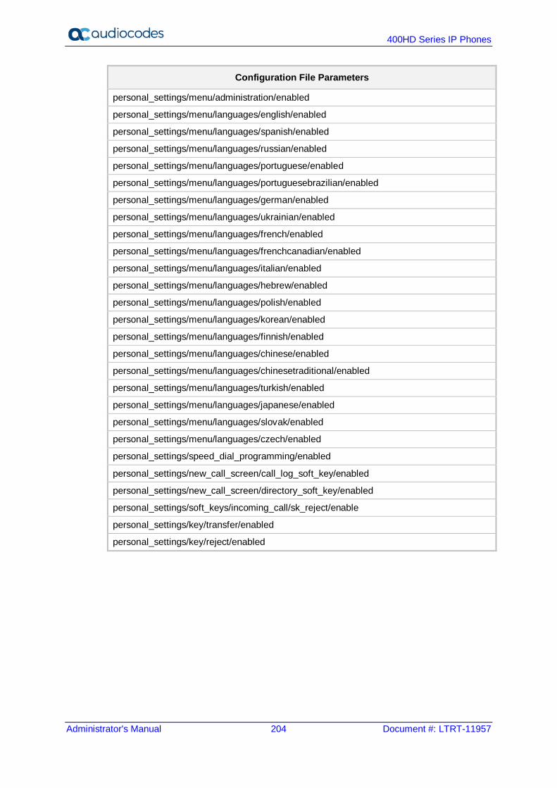
400HD Series IP Phones
Administrator's Manual 204 Document #: LTRT-11957
Configuration File Parameters
personal_settings/menu/administration/enabled
personal_settings/menu/languages/english/enabled
personal_settings/menu/languages/spanish/enabled
personal_settings/menu/languages/russian/enabled
personal_settings/menu/languages/portuguese/enabled
personal_settings/menu/languages/portuguesebrazilian/enabled
personal_settings/menu/languages/german/enabled
personal_settings/menu/languages/ukrainian/enabled
personal_settings/menu/languages/french/enabled
personal_settings/menu/languages/frenchcanadian/enabled
personal_settings/menu/languages/italian/enabled
personal_settings/menu/languages/hebrew/enabled
personal_settings/menu/languages/polish/enabled
personal_settings/menu/languages/korean/enabled
personal_settings/menu/languages/finnish/enabled
personal_settings/menu/languages/chinese/enabled
personal_settings/menu/languages/chinesetraditional/enabled
personal_settings/menu/languages/turkish/enabled
personal_settings/menu/languages/japanese/enabled
personal_settings/menu/languages/slovak/enabled
personal_settings/menu/languages/czech/enabled
personal_settings/speed_dial_programming/enabled
personal_settings/new_call_screen/call_log_soft_key/enabled
personal_settings/new_call_screen/directory_soft_key/enabled
personal_settings/soft_keys/incoming_call/sk_reject/enable
personal_settings/key/transfer/enabled
personal_settings/key/reject/enabled
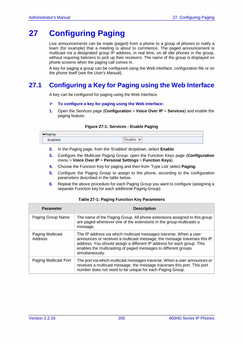
Administrator's Manual 27. Configuring Paging
Version 2.2.16 205 400HD Series IP Phones
27 Configuring Paging Live announcements can be made (paged) from a phone to a group of phones to notify a team (for example) that a meeting is about to commence. The paged announcement is multicast via a designated group IP address, in real time, on all idle phones in the group, without requiring listeners to pick up their receivers. The name of the group is displayed on phone screens when the paging call comes in. A key for paging a group can be configured using the Web interface, configuration file or on the phone itself (see the User's Manual).
27.1 Configuring a Key for Paging using the Web Interface A key can be configured for paging using the Web Interface.
To configure a key for paging using the Web interface: 1. Open the Services page (Configuration > Voice Over IP > Services) and enable the
paging feature.
Figure 27-1: Services - Enable Paging
2. In the Paging page, from the 'Enabled' dropdown, select Enable. 3. Configure the Multicast Paging Group; open the Function Keys page (Configuration
menu > Voice Over IP > Personal Settings > Function Keys). 4. Choose the Function Key for paging and then from 'Type List' select Paging. 5. Configure the Paging Group to assign to the phone, according to the configuration
parameters described in the table below. 6. Repeat the above procedure for each Paging Group you want to configure (assigning a
separate Function key for each additional Paging Group).
Table 27-1: Paging Function Key Parameters
Parameter Description
Paging Group Name The name of the Paging Group. All phone extensions assigned to this group are paged whenever one of the extensions in the group multicasts a message.
Paging Multicast Address
The IP address via which multicast messages traverse. When a user announces or receives a multicast message, the message traverses this IP address. You should assign a different IP address for each group. This enables the multicasting of paged messages to different groups simultaneously.
Paging Multicast Port The port via which multicast messages traverse. When a user announces or receives a multicast message, the message traverses this port. This port number does not need to be unique for each Paging Group.
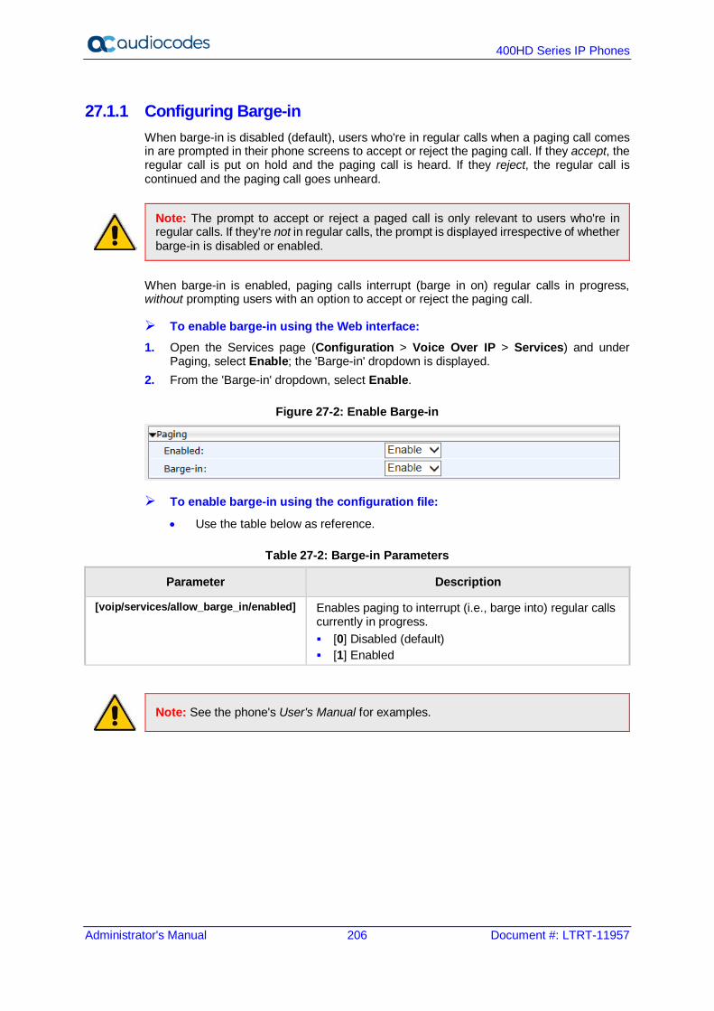
400HD Series IP Phones
Administrator's Manual 206 Document #: LTRT-11957
27.1.1 Configuring Barge-in When barge-in is disabled (default), users who're in regular calls when a paging call comes in are prompted in their phone screens to accept or reject the paging call. If they accept, the regular call is put on hold and the paging call is heard. If they reject, the regular call is continued and the paging call goes unheard.
Note: The prompt to accept or reject a paged call is only relevant to users who're in regular calls. If they're not in regular calls, the prompt is displayed irrespective of whether barge-in is disabled or enabled.
When barge-in is enabled, paging calls interrupt (barge in on) regular calls in progress, without prompting users with an option to accept or reject the paging call.
To enable barge-in using the Web interface: 1. Open the Services page (Configuration > Voice Over IP > Services) and under
Paging, select Enable; the 'Barge-in' dropdown is displayed. 2. From the 'Barge-in' dropdown, select Enable.
Figure 27-2: Enable Barge-in
To enable barge-in using the configuration file:
• Use the table below as reference.
Table 27-2: Barge-in Parameters
Parameter Description
[voip/services/allow_barge_in/enabled] Enables paging to interrupt (i.e., barge into) regular calls currently in progress. [0] Disabled (default) [1] Enabled
Note: See the phone's User's Manual for examples.

Administrator's Manual 27. Configuring Paging
Version 2.2.16 207 400HD Series IP Phones
27.2 Configuring Paging Using the Configuration File Here's how to configure the paging feature using the configuration file.
To configure paging using the configuration file:
• Use the table below as reference.
Table 27-3: Configuration File Paging Parameters
Parameter Description
[voip/services/group_paging/enabled] Enables group paging. [0] Disabled (default) [1] Enabled
[voip/services/group_paging/group/0-11/activated]
Defines the group to page to. Default: Group 0
[voip/services/group_paging/group/0-11/multicast_addr]
Defines the multicast address for group 0-11 to page to. Default: 224.0.1.0
[voip/services/group_paging/group/0-11/name]
Defines the paging group name to display in the screen.
[voip/services/group_paging/group/0-11/port]
Defines the multicast port for group 0 to page to. Default: 8888
[voip/services/group_paging/codec] The codec of the paging RTP. Since the phones have many DSP versions and different DSPs support different codecs, the codec of the paging call can be configured. Available options are: PCMU,PCMA G729 G722 G723 G726 RTA RTA_WB G722_8000 Note: Phones that are in the same paging group must use the same codec.
[voip/services/group_paging/end_income_paging_timeout]
Defines the timeout that begins after the phone detects that it is not receiving RTP. The phone ends the incoming paging call when the timeout expires. Default: 800 milliseconds. Optionally, you can configure 800~ milliseconds to 100000 milliseconds.

400HD Series IP Phones
Administrator's Manual 208 Document #: LTRT-11957
This page is intentionally left blank.
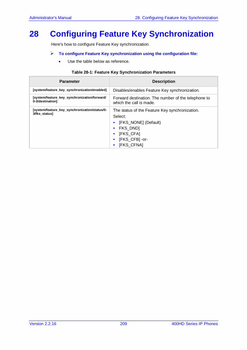
Administrator's Manual 28. Configuring Feature Key Synchronization
Version 2.2.16 209 400HD Series IP Phones
28 Configuring Feature Key Synchronization Here's how to configure Feature Key synchronization.
To configure Feature Key synchronization using the configuration file:
• Use the table below as reference.
Table 28-1: Feature Key Synchronization Parameters
Parameter Description
[system/feature_key_synchronization/enabled] Disables/enables Feature Key synchronization. [system/feature_key_synchronization/forward/0-3/destination]
Forward destination. The number of the telephone to which the call is made.
[system/feature_key_synchronization/status/0-3/fks_status]
The status of the Feature Key synchronization. Select: [FKS_NONE] (Default) FKS_DND] [FKS_CFA] [FKS_CFB] -or- [FKS_CFNA]

400HD Series IP Phones
Administrator's Manual 210 Document #: LTRT-11957
This page is intentionally left blank.

Part VII Security

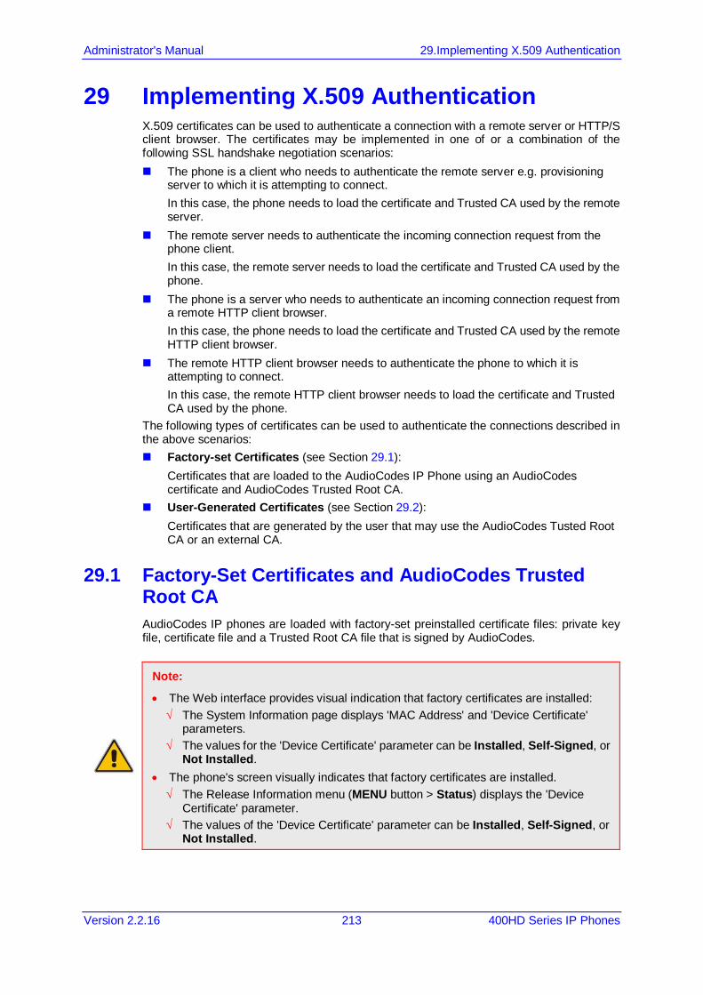
Administrator's Manual 29.Implementing X.509 Authentication
Version 2.2.16 213 400HD Series IP Phones
29 Implementing X.509 Authentication X.509 certificates can be used to authenticate a connection with a remote server or HTTP/S client browser. The certificates may be implemented in one of or a combination of the following SSL handshake negotiation scenarios: The phone is a client who needs to authenticate the remote server e.g. provisioning
server to which it is attempting to connect. In this case, the phone needs to load the certificate and Trusted CA used by the remote server.
The remote server needs to authenticate the incoming connection request from the phone client. In this case, the remote server needs to load the certificate and Trusted CA used by the phone.
The phone is a server who needs to authenticate an incoming connection request from a remote HTTP client browser. In this case, the phone needs to load the certificate and Trusted CA used by the remote HTTP client browser.
The remote HTTP client browser needs to authenticate the phone to which it is attempting to connect. In this case, the remote HTTP client browser needs to load the certificate and Trusted CA used by the phone.
The following types of certificates can be used to authenticate the connections described in the above scenarios: Factory-set Certificates (see Section 29.1):
Certificates that are loaded to the AudioCodes IP Phone using an AudioCodes certificate and AudioCodes Trusted Root CA.
User-Generated Certificates (see Section 29.2): Certificates that are generated by the user that may use the AudioCodes Tusted Root CA or an external CA.
29.1 Factory-Set Certificates and AudioCodes Trusted Root CA AudioCodes IP phones are loaded with factory-set preinstalled certificate files: private key file, certificate file and a Trusted Root CA file that is signed by AudioCodes.
Note:
• The Web interface provides visual indication that factory certificates are installed: √ The System Information page displays 'MAC Address' and 'Device Certificate'
parameters. √ The values for the 'Device Certificate' parameter can be Installed, Self-Signed, or
Not Installed. • The phone's screen visually indicates that factory certificates are installed. √ The Release Information menu (MENU button > Status) displays the 'Device
Certificate' parameter. √ The values of the 'Device Certificate' parameter can be Installed, Self-Signed, or
Not Installed.
400HD Series IP Phones
Administrator's Manual 214 Document #: LTRT-11957
Whenever the phone authenticates with a remote server, it can be authenticated using these certificate files. Each phone receives a uniquely generated private key certificate file based on its MAC address.
Note:
• If the remote server is configured to authenticate the client and AudioCodes factory-set certificates are used for authentication, then the AudioCodes Certificate and AudioCodes Trusted Root CA must be downloaded to the remote server. These files can be downloaded from the AudioCodes Web site. For more information, contact your local AudioCodes sales representative.
• If you use the AudioCodes Redirect server to obtain firmware and configuration files, then the factory-set certificates are used to authenticate the connection with this server.
29.2 User-Generated Certificates If an organizational certificate Infrastructure (PKI) is used, you may wish to instead use certificates provided by your security administrator. You can define up to five additional user-generated certificates, which can be configured to secure different types of connections and paired with external Trusted Root CAs. The following remote server connection types can be configured with user-generated certificates: 802.1x RADIUS server SIP TLS server HTTP/S Provisioning server When user-generated certificates are loaded to the device to authenticate a specific connection type, then this certificate is used to secure the connection with the assigned connection type. For example, if you load Certificate A for connecting to an HTTPS Provisioning server, then whenever there is an attempt by the phone to connect to a Provisioning server, then the connection is authenticated using Certificate A.
Note:
• You can load one certificate for each connection type. • If you do not load a certificate to support a specific connection type, then the
factory-set certificate is used to authenticate the connection. For example if you load user-generated certificates to support Automatic Updates (Provisioning server) and SIP TLS server connections, and there is an attempt by the phone to connect to a RADIUS server, then this connection is authenticated using the AudioCodes factory-set installed certificate.
• You can use the AudioCodes Trusted Root CA with a user-generated certificate. • You can use the same certificate for different server connection types.
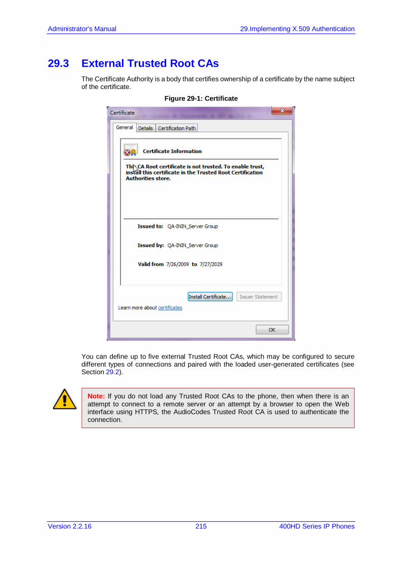
Administrator's Manual 29.Implementing X.509 Authentication
Version 2.2.16 215 400HD Series IP Phones
29.3 External Trusted Root CAs The Certificate Authority is a body that certifies ownership of a certificate by the name subject of the certificate.
Figure 29-1: Certificate
You can define up to five external Trusted Root CAs, which may be configured to secure different types of connections and paired with the loaded user-generated certificates (see Section 29.2).
Note: If you do not load any Trusted Root CAs to the phone, then when there is an attempt to connect to a remote server or an attempt by a browser to open the Web interface using HTTPS, the AudioCodes Trusted Root CA is used to authenticate the connection.

400HD Series IP Phones
Administrator's Manual 216 Document #: LTRT-11957
This page is left intentionally blank.

Administrator's Manual 30.Loading a Certificate
Version 2.2.16 217 400HD Series IP Phones
30 Loading a Certificate Here's how to: Load the Trusted Root CA Certificate to the Phone (see below). Load the Client Certificate to the Phone (see Section 30.2). Generate a Certificate Signing Request (CSR) (see Section 30.3).
30.1 Loading the Trusted Root CA Certificate to the Phone Here's how to load the Trusted Root CA certificate to the phone.
To load the trusted root CA certificate to the phone: 1. Open the Root CA Certificate page (Configuration tab > Security menu > Root CA
Certificate).
Figure 30-1: Root CA Certificate
2. Click Browse to navigate to the certificate file, and then click the Load button to upload
it to the phone. You can load a maximum of five certificates to the phone. Click the Del button to delete a load if necessary. Click the Display button to display the certificate if you wish to view it.
30.1.1 Loading Trusted Root CA Certificate Using Configuration File Here's how to load a Trusted Root CA certificate using the configuration file.
Note: Using this method, Trusted Root CA certificates files are loaded to the phone when it is powered up.
To load a Trusted Root CA certificate file using the configuration file:
• Use the table below as reference.
Table 30-1: Root CA Certificate Parameters
Parameter Description
Root CA 1 [security/ca_certificate/0/uri]
The first root CA certificate loaded to the phone.
Root CA 2 [security/ca_certificate/1/uri]
The second root CA certificate loaded to the phone.
Root CA 3 [security/ca_certificate/2/uri]
The third root CA certificate loaded to the phone.

400HD Series IP Phones
Administrator's Manual 218 Document #: LTRT-11957
Parameter Description
Root CA 4 [security/ca_certificate/3/uri]
The fourth root CA certificate loaded to the phone.
Root CA 5 [security/ca_certificate/4/uri]
The fifth root CA certificate loaded to the phone.
30.2 Loading the Client Certificate to the Phone The section shows how to load the Client Certificate to the phone.
To load the Client Certificate to the phone: 1. Open the Client Certificate page (Configuration tab > Security menu > Client
Certificate).
Figure 30-2: Client Certificate
30.2.1 Loading the Client Certificate to the Phone using the Configuration File Here's how to load a Client Certificate file to the phone using the configuration file.
Note: Using this method, client certificates files are loaded to the phone when it is powered up.
To load a client certificate file using the configuration file:
• Use the table below as reference.
Table 30-2: Client Certificate Parameters
Parameter Description
Certificate [security/sip_certificate_uri]
Downloads from this URI to the phone a Client Certificate for SIP TLS (SIP calls with Transport Layer Security).
Private Key [security/sip_private_key_uri]
Downloads from this URI to the phone a Client Private Key for SIP TLS (SIP calls with Transport Layer Security).
Certificate [security/ieee802_1x_certificate_uri]
Downloads from this URI to the phone a Client Certificate for 802.1X Authentication.
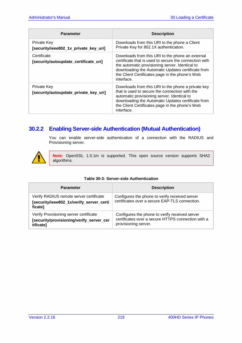
Administrator's Manual 30.Loading a Certificate
Version 2.2.16 219 400HD Series IP Phones
Parameter Description
Private Key [security/ieee802_1x_private_key_uri]
Downloads from this URI to the phone a Client Private Key for 802.1X authentication.
Certificate [security/autoupdate_certificate_uri]
Downloads from this URI to the phone an external certificate that is used to secure the connection with the automatic provisioning server. Identical to downloading the Automatic Updates certificate from the Client Certificates page in the phone’s Web interface.
Private Key [security/autoupdate_private_key_uri]
Downloads from this URI to the phone a private key that is used to secure the connection with the automatic provisioning server. Identical to downloading the Automatic Updates certificate from the Client Certificates page in the phone’s Web interface.
30.2.2 Enabling Server-side Authentication (Mutual Authentication) You can enable server-side authentication of a connection with the RADIUS and Provisioning server.
Note: OpenSSL 1.0.1m is supported. This open source version supports SHA2 algorithms.
Table 30-3: Server-side Authentication
Parameter Description
Verify RADIUS remote server certificate [security/ieee802_1x/verify_server_certificate]
Configures the phone to verify received server certificates over a secure EAP-TLS connection.
Verify Provisioning server certificate [security/provisioning/verify_server_certificate]
Configures the phone to verify received server certificates over a secure HTTPS connection with a provisioning server.
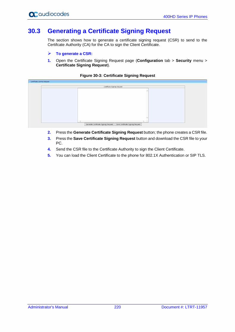
400HD Series IP Phones
Administrator's Manual 220 Document #: LTRT-11957
30.3 Generating a Certificate Signing Request The section shows how to generate a certificate signing request (CSR) to send to the Certifcate Authority (CA) for the CA to sign the Client Certificate.
To generate a CSR: 1. Open the Certificate Signing Request page (Configuration tab > Security menu >
Certificate Signing Request).
Figure 30-3: Certificate Signing Request
2. Press the Generate Certificate Signing Request button; the phone creates a CSR file. 3. Press the Save Certificate Signing Request button and download the CSR file to your
PC. 4. Send the CSR file to the Certificate Authority to sign the Client Certificate. 5. You can load the Client Certificate to the phone for 802.1X Authentication or SIP TLS.
Administrator's Manual 30.Loading a Certificate
Version 2.2.16 221 400HD Series IP Phones
30.4 Using Previously Loaded Certificates If you have upgraded to this version and your phones have pre-installed certificates, then the CA configuration parameter values from previous versions are translated to version 2.2.2 parameter values as described below.
Note: It is highly recommended to change the CA configuration by using the methods described in the above sections.
Certificate file settings for versions prior to version 2.2.2: security/ca_certificate_uri= xxx security/certificate_uri=zzz security/private_key_uri=yyy
where: xxx is the uri of the root CA zzz is the uri of the certificate file yyy is the uri of the private key file Certificate file settings translated to version 2.2.2: security/autoupdate_certificate_uri=zzz security/autoupdate_private_key_uri= yyy security/ca_certificate/0/uri=xxx security/ca_certificate/1/uri= security/ca_certificate/2/uri= security/ca_certificate/3/uri= security/ca_certificate/4/uri= security/ieee802_1x_certificate_uri=zzz security/ieee802_1x_private_key_uri= yyy security/sip_certificate_uri= zzz security/sip_private_key_uri= yyy
Note: The CA configuration parameters prior to version 2.2.2 are no longer used on the phone.

400HD Series IP Phones
Administrator's Manual 222 Document #: LTRT-11957
This page is left intentionally blank
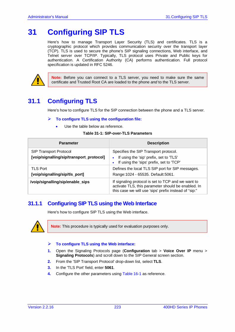
Administrator's Manual 31.Configuring SIP TLS
Version 2.2.16 223 400HD Series IP Phones
31 Configuring SIP TLS Here's how to manage Transport Layer Security (TLS) and certificates. TLS is a cryptographic protocol which provides communication security over the transport layer (TCP). TLS is used to secure the phone's SIP signaling connections, Web interface, and Telnet server over TCP/IP. Typically, TLS protocol uses Private and Public keys for authentication. A Certification Authority (CA) performs authentication. Full protocol specification is updated in RFC 5246.
Note: Before you can connect to a TLS server, you need to make sure the same certificate and Trusted Root CA are loaded to the phone and to the TLS server.
31.1 Configuring TLS Here's how to configure TLS for the SIP connection between the phone and a TLS server.
To configure TLS using the configuration file:
• Use the table below as reference.
Table 31-1: SIP-over-TLS Parameters
Parameter Description
SIP Transport Protocol [voip/signalling/sip/transport_protocol]
Specifies the SIP Transport protocol. • If using the 'sip' prefix, set to 'TLS' • If using the 'sips' prefix, set to 'TCP'
TLS Port [voip/signalling/sip/tls_port]
Defines the local TLS SIP port for SIP messages. Range:1024 - 65535. Default:5061.
/voip/signalling/sip/enable_sips If signaling protocol is set to TCP and we want to activate TLS, this parameter should be enabled. In this case we will use 'sips' prefix instead of “sip:”
31.1.1 Configuring SIP TLS using the Web Interface Here's how to configure SIP TLS using the Web interface.
Note: This procedure is typically used for evaluation purposes only.
To configure TLS using the Web interface: 1. Open the Signaling Protocols page (Configuration tab > Voice Over IP menu >
Signaling Protocols) and scroll down to the SIP General screen section. 2. From the 'SIP Transport Protocol' drop-down list, select TLS. 3. In the 'TLS Port' field, enter 5061. 4. Configure the other parameters using Table 16-1 as reference.

400HD Series IP Phones
Administrator's Manual 224 Document #: LTRT-11957
Figure 31-1: Signaling Protocols - SIP General
5. Click Submit.

Administrator's Manual 32.Configuring 802.1x
Version 2.2.16 225 400HD Series IP Phones
32 Configuring 802.1x 802.1X is an IEEE Standard for Port-based Network Access Control (PNAC). It's part of the IEEE 802.1 group of networking protocols. It provides an authentication mechanism for devices wishing to connect to a LAN or WLAN. The employee's PC negotiates 802.1X. Messages are sent transparent to the enterprise switch. The phone is uninvolved in the negotiation; however, if an employee's PC is disconnected, their phone notifies the switch. If an employee's PC is disconnected from the phone, a PROXY-EAP-LOGOFF mechanism lets the phone immediately log off the port from the authentication server to prevent anyone else from connecting to it. The phone performs like this: Phone and PC connected to phone's PC port successfully perform 802.1X
authentication. The authentication server records the phone and PC as authorized. If the PC is disconnected from the phone's PC port, the phone sends an EAPoL-Logoff
message for the PC. The authentication server then records the PC as unauthorized. If the PC reconnects to the phone's PC port, the authentication server requests the PC
to perform 802.1X authentication again.
Note: Before you can connect to a 802.1x server, you need to make sure the same certificate and Trusted Root CA are loaded to the phone and to the 802.1x.
32.1 Configuring 802.1x in the Phone Screen Here's how to configure 802.1x in the phone screen.
To configure 802.1x in the phone screen: 1. On the phone, open the 802.1x Settings screen (MENU key > Administration >
Network Settings > 802.1xSettings).
2. Navigate to and select either:
• Disabled – disables the 802.1x feature • EAP-MD5 – see Section 32.1.1 • EAP-TLS - see Section 32.1.2
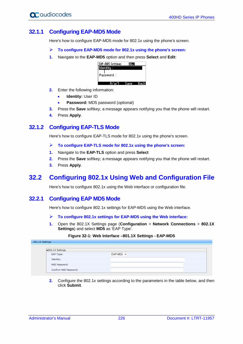
400HD Series IP Phones
Administrator's Manual 226 Document #: LTRT-11957
32.1.1 Configuring EAP-MD5 Mode Here's how to configure EAP-MD5 mode for 802.1x using the phone's screen.
To configure EAP-MD5 mode for 802.1x using the phone's screen: 1. Navigate to the EAP-MD5 option and then press Select and Edit:
2. Enter the following information:
• Identity: User ID • Password: MD5 password (optional)
3. Press the Save softkey; a message appears notifying you that the phone will restart. 4. Press Apply.
32.1.2 Configuring EAP-TLS Mode Here's how to configure EAP-TLS mode for 802.1x using the phone's screen.
To configure EAP-TLS mode for 802.1x using the phone's screen: 1. Navigate to the EAP-TLS option and press Select 2. Press the Save softkey; a message appears notifying you that the phone will restart. 3. Press Apply.
32.2 Configuring 802.1x Using Web and Configuration File Here's how to configure 802.1x using the Web interface or configuration file.
32.2.1 Configuring EAP MD5 Mode Here's how to configure 802.1x settings for EAP-MD5 using the Web interface.
To configure 802.1x settings for EAP-MD5 using the Web interface: 1. Open the 802.1X Settings page (Configuration > Network Connections > 802.1X
Settings) and select MD5 as 'EAP Type'.
Figure 32-1: Web Interface –801.1X Settings - EAP-MD5
2. Configure the 802.1x settings according to the parameters in the table below, and then
click Submit.
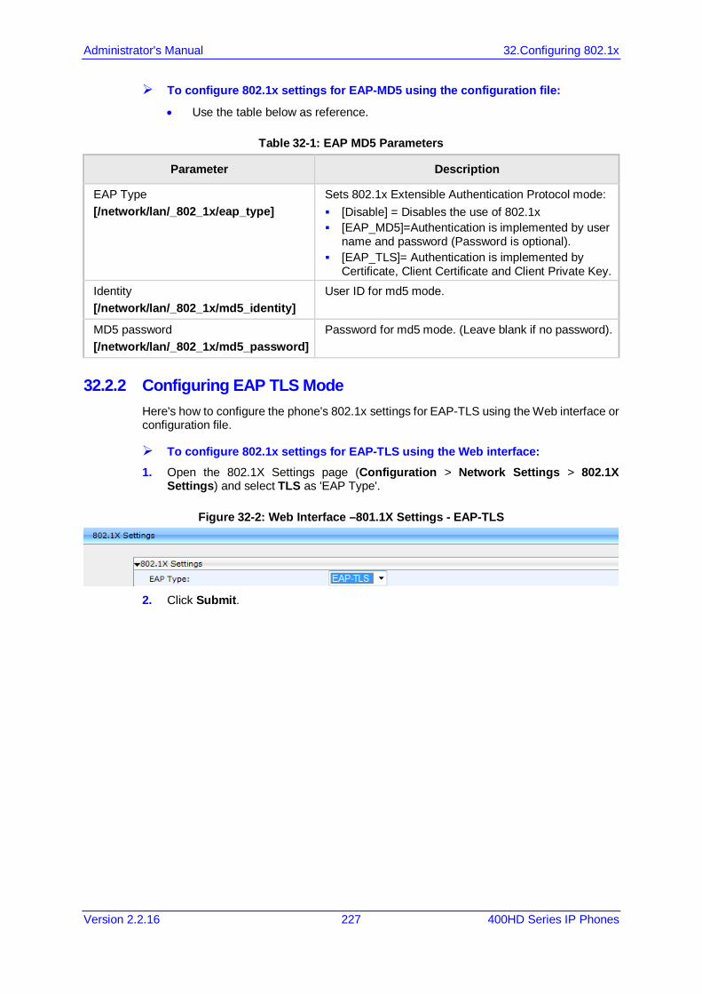
Administrator's Manual 32.Configuring 802.1x
Version 2.2.16 227 400HD Series IP Phones
To configure 802.1x settings for EAP-MD5 using the configuration file:
• Use the table below as reference.
Table 32-1: EAP MD5 Parameters
Parameter Description
EAP Type [/network/lan/_802_1x/eap_type]
Sets 802.1x Extensible Authentication Protocol mode: [Disable] = Disables the use of 802.1x [EAP_MD5]=Authentication is implemented by user
name and password (Password is optional). [EAP_TLS]= Authentication is implemented by
Certificate, Client Certificate and Client Private Key. Identity [/network/lan/_802_1x/md5_identity]
User ID for md5 mode.
MD5 password [/network/lan/_802_1x/md5_password]
Password for md5 mode. (Leave blank if no password).
32.2.2 Configuring EAP TLS Mode Here's how to configure the phone's 802.1x settings for EAP-TLS using the Web interface or configuration file.
To configure 802.1x settings for EAP-TLS using the Web interface: 1. Open the 802.1X Settings page (Configuration > Network Settings > 802.1X
Settings) and select TLS as 'EAP Type'.
Figure 32-2: Web Interface –801.1X Settings - EAP-TLS
2. Click Submit.

400HD Series IP Phones
Administrator's Manual 228 Document #: LTRT-11957
This page is left intentionally blank

Administrator's Manual 33.Configuring SRTP
Version 2.2.16 229 400HD Series IP Phones
33 Configuring SRTP Secure Real-time Transport Protocol (SRTP) is a protocol that allows encryption for RTP data. Since the RTP encryption key is delivered via SIP, this feature is relevant only when SIP transport is secured, so when using this feature you also need to use SIP over TLS. SRTP can be configured using the Web interface or configuration file.
To configure SRTP using the Web interface: 1. Open the Media Streaming page (Configuration tab > Voice Over IP menu > Media
Streaming) and scroll down to SRTP.
Figure 33-1: SRTP
• One of three supported levels of encryption can be selected from the drop-down
list: ♦ DO NOT SUPPORT ENCRYPTION [Default] [SRTP is disabled] ♦ SUPPORT ENCRYPTION [Negotiation] ♦ REQUIRE ENCRYPTION [SRTP is enabled; both sides must support
encryption] 2. Configure the SRTP settings using the parameter descriptions in the table below as
reference, and then click Submit.
To configure SRTP using the configuration file:
• Use the table below as reference.
Table 33-1: SRTP Parameters
Parameter Description
SRTP Encryption and Authentication [voip/media/srtp/mode]
Three levels of encryption are supported: DO NOT SUPPORT ENCRYPTION [Default]
[SRTP is disabled] SUPPORT ENCRYPTION [Negotiation] REQUIRE ENCRYPTION [SRTP is enabled; both
sides must support encryption] Note regarding backward compatibility: In Version 2.2.16, this configuration file parameter replaced the legacy 'voip/media/srtp/enabled' configuration file parameter. If the network administrator configured phones to 'voip/media/srtp/enabled=1' in a release before Version 2.2.16, in this release they must configure 'voip/media/srtp/mode=RequireEncryption’ to keep forcing SRTP.
[voip/media/srtp/aria_support_enabled] Enables use of the ARIA block cipher algorithm within the SRTP. [0] Disabled (default) [1] Enabled
Method [voip/media/srtp/method]
The SRTP encryption method. [AES_CM_128_HMAC_SHA1_32] (default) [AES_CM_128_HMAC_SHA1_80] [AES_CM_128_ALL_METHODS]
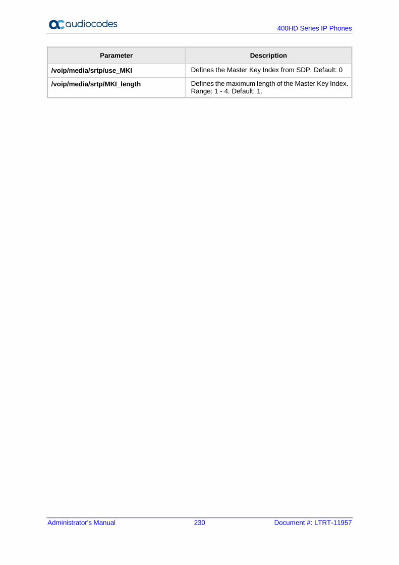
400HD Series IP Phones
Administrator's Manual 230 Document #: LTRT-11957
Parameter Description
/voip/media/srtp/use_MKI Defines the Master Key Index from SDP. Default: 0
/voip/media/srtp/MKI_length Defines the maximum length of the Master Key Index. Range: 1 - 4. Default: 1.

Administrator's Manual 34.Configuring HTTP/S
Version 2.2.16 231 400HD Series IP Phones
34 Configuring HTTP/S HTTP/S login authentication can be configured to secure the connection between the phones and a provisioning server, such as the BroadWorks Device Management Provisioning server. Once the connection is secure, software and/or configuration files can be downloaded to the phone. HTTP/S authentication is supporting using the following methods (configured on the remote server): Basic – (RFC 2617) username and password are sent in plain text over plain HTTP
over the network. Digest – a hash function is applied to the password before sending it over the network,
therefore it is more secure as usernames and passwords are encrypted
Note:
• The enterprise requires an HTTP/S server to support this feature. • The authentication method is configured on the remote side e.g. Provisioning server.

400HD Series IP Phones
Administrator's Manual 232 Document #: LTRT-11957
This page is intentionally left blank.
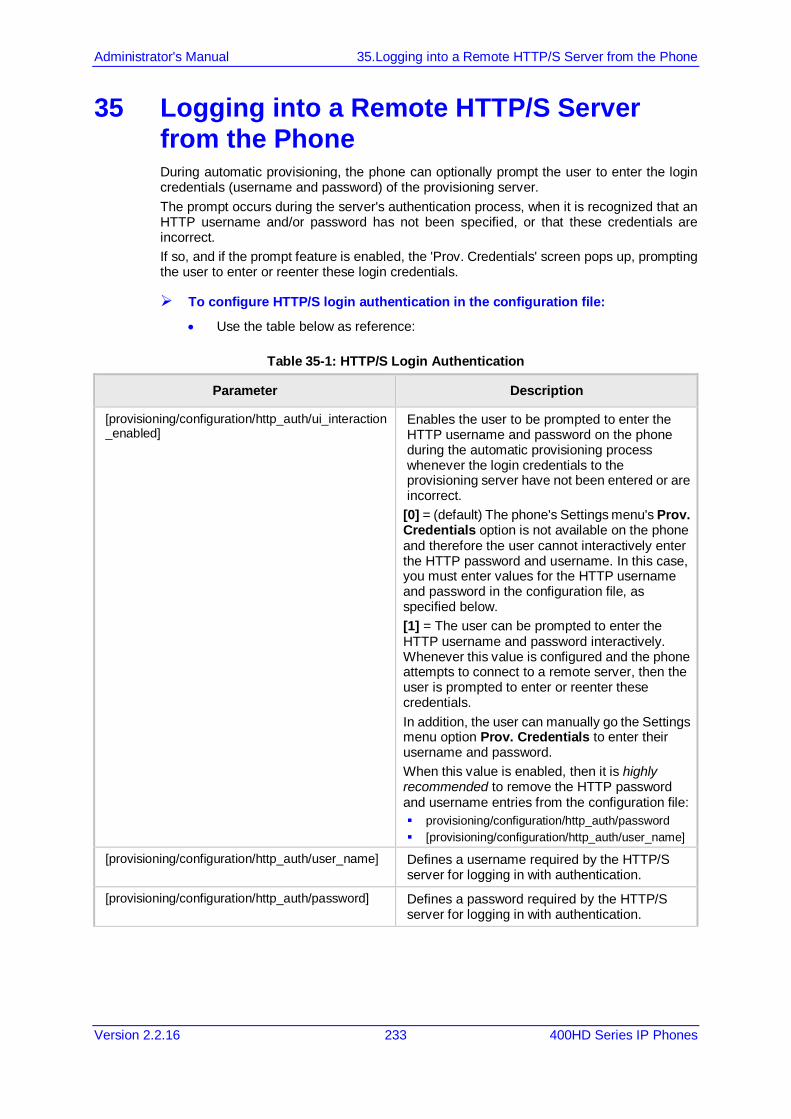
Administrator's Manual 35.Logging into a Remote HTTP/S Server from the Phone
Version 2.2.16 233 400HD Series IP Phones
35 Logging into a Remote HTTP/S Server from the Phone During automatic provisioning, the phone can optionally prompt the user to enter the login credentials (username and password) of the provisioning server. The prompt occurs during the server's authentication process, when it is recognized that an HTTP username and/or password has not been specified, or that these credentials are incorrect. If so, and if the prompt feature is enabled, the 'Prov. Credentials' screen pops up, prompting the user to enter or reenter these login credentials.
To configure HTTP/S login authentication in the configuration file:
• Use the table below as reference:
Table 35-1: HTTP/S Login Authentication
Parameter Description
[provisioning/configuration/http_auth/ui_interaction_enabled]
Enables the user to be prompted to enter the HTTP username and password on the phone during the automatic provisioning process whenever the login credentials to the provisioning server have not been entered or are incorrect.
[0] = (default) The phone's Settings menu's Prov. Credentials option is not available on the phone and therefore the user cannot interactively enter the HTTP password and username. In this case, you must enter values for the HTTP username and password in the configuration file, as specified below. [1] = The user can be prompted to enter the HTTP username and password interactively. Whenever this value is configured and the phone attempts to connect to a remote server, then the user is prompted to enter or reenter these credentials. In addition, the user can manually go the Settings menu option Prov. Credentials to enter their username and password. When this value is enabled, then it is highly recommended to remove the HTTP password and username entries from the configuration file: provisioning/configuration/http_auth/password [provisioning/configuration/http_auth/user_name]
[provisioning/configuration/http_auth/user_name] Defines a username required by the HTTP/S server for logging in with authentication.
[provisioning/configuration/http_auth/password] Defines a password required by the HTTP/S server for logging in with authentication.

400HD Series IP Phones
Administrator's Manual 234 Document #: LTRT-11957
This page is intentionally left blank.
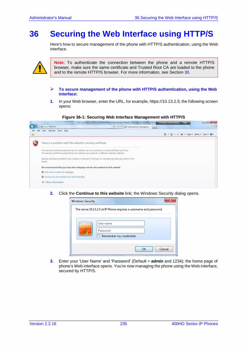
Administrator's Manual 36.Securing the Web Interface using HTTP/S
Version 2.2.16 235 400HD Series IP Phones
36 Securing the Web Interface using HTTP/S Here's how to secure management of the phone with HTTP/S authentication, using the Web interface.
Note: To authenticate the connection between the phone and a remote HTTP/S browser, make sure the same certificate and Trusted Root CA are loaded to the phone and to the remote HTTP/S browser. For more information, see Section 30.
To secure management of the phone with HTTP/S authentication, using the Web interface:
1. In your Web browser, enter the URL, for example, https://10.13.2.5; the following screen opens:
Figure 36-1: Securing Web Interface Management with HTTP/S
2. Click the Continue to this website link; the Windows Security dialog opens.
3. Enter your 'User Name' and 'Password' (Default = admin and 1234); the home page of
phone's Web interface opens. You're now managing the phone using the Web interface, secured by HTTP/S.
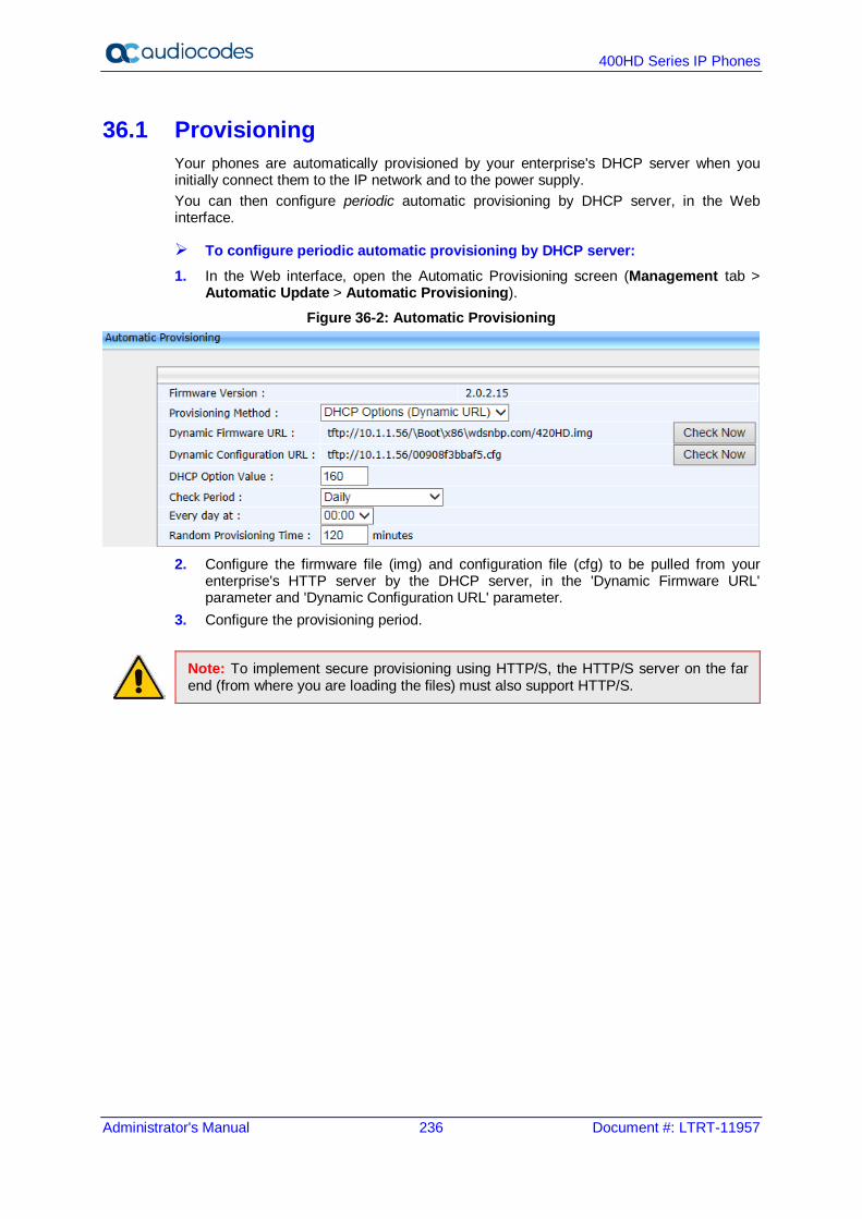
400HD Series IP Phones
Administrator's Manual 236 Document #: LTRT-11957
36.1 Provisioning Your phones are automatically provisioned by your enterprise's DHCP server when you initially connect them to the IP network and to the power supply. You can then configure periodic automatic provisioning by DHCP server, in the Web interface.
To configure periodic automatic provisioning by DHCP server: 1. In the Web interface, open the Automatic Provisioning screen (Management tab >
Automatic Update > Automatic Provisioning).
Figure 36-2: Automatic Provisioning
2. Configure the firmware file (img) and configuration file (cfg) to be pulled from your
enterprise's HTTP server by the DHCP server, in the 'Dynamic Firmware URL' parameter and 'Dynamic Configuration URL' parameter.
3. Configure the provisioning period.
Note: To implement secure provisioning using HTTP/S, the HTTP/S server on the far end (from where you are loading the files) must also support HTTP/S.

Administrator's Manual 37.MAC-Based Authenticaton
Version 2.2.16 237 400HD Series IP Phones
37 MAC-Based Authenticaton Here's how to configure MAC-based authentication.
To configure MAC-based authentication:
• Use the table below as reference:
Table 37-1: Authentication
Parameter Description
[provisioning/configuration/mac_address_in_header]
Enables MAC-based authentication. [0] = (default) Don't insert the phone's MAC address in the header. [1] = Insert the phone's MAC address in the header.

400HD Series IP Phones
Administrator's Manual 238 Document #: LTRT-11957
This page is intentionally left blank.
Part VIII Maintenance

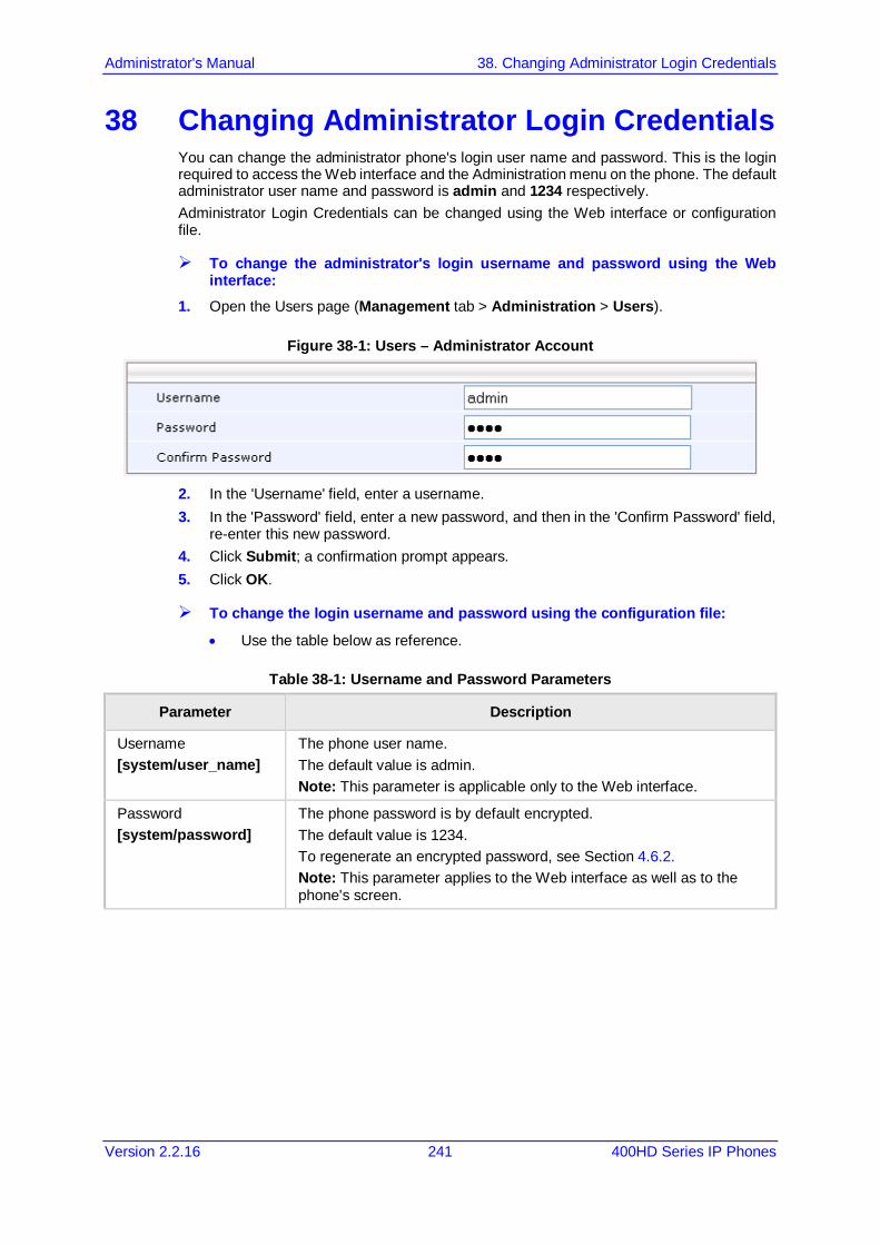
Administrator's Manual 38. Changing Administrator Login Credentials
Version 2.2.16 241 400HD Series IP Phones
38 Changing Administrator Login Credentials You can change the administrator phone's login user name and password. This is the login required to access the Web interface and the Administration menu on the phone. The default administrator user name and password is admin and 1234 respectively. Administrator Login Credentials can be changed using the Web interface or configuration file.
To change the administrator's login username and password using the Web interface:
1. Open the Users page (Management tab > Administration > Users).
Figure 38-1: Users – Administrator Account
2. In the 'Username' field, enter a username. 3. In the 'Password' field, enter a new password, and then in the 'Confirm Password' field,
re-enter this new password. 4. Click Submit; a confirmation prompt appears. 5. Click OK.
To change the login username and password using the configuration file:
• Use the table below as reference.
Table 38-1: Username and Password Parameters
Parameter Description
Username [system/user_name]
The phone user name. The default value is admin. Note: This parameter is applicable only to the Web interface.
Password [system/password]
The phone password is by default encrypted. The default value is 1234. To regenerate an encrypted password, see Section 4.6.2. Note: This parameter applies to the Web interface as well as to the phone's screen.

400HD Series IP Phones
Administrator's Manual 242 Document #: LTRT-11957
This page is intentionally left blank.
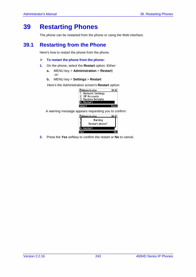
Administrator's Manual 39. Restarting Phones
Version 2.2.16 243 400HD Series IP Phones
39 Restarting Phones The phone can be restarted from the phone or using the Web interface.
39.1 Restarting from the Phone Here's how to restart the phone from the phone.
To restart the phone from the phone: 1. On the phone, select the Restart option. Either:
a. MENU key > Administration > Restart) -or-
b. MENU key > Settings > Restart Here's the Administration screen's Restart option:
A warning message appears requesting you to confirm:
2. Press the Yes softkey to confirm the restart or No to cancel.

400HD Series IP Phones
Administrator's Manual 244 Document #: LTRT-11957
39.2 Restarting the Phone using the Web Interface You can use the Web interface to restart your phone.
To restart the phone: 1. Open the Restart System page (Management > Administration > Restart System).
Figure 39-1: Restart System
2. Click the Restart button; a confirmation box appears prompting you to confirm.
Figure 39-2: Confirmation Box
3. Click OK.
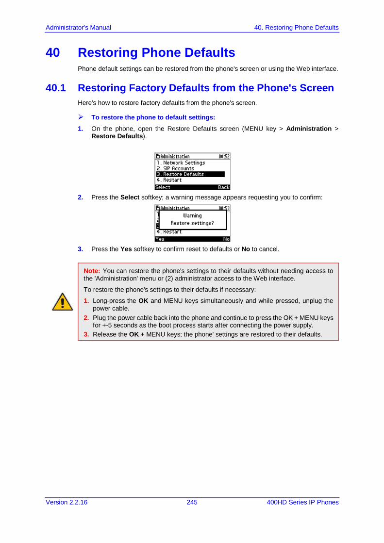
Administrator's Manual 40. Restoring Phone Defaults
Version 2.2.16 245 400HD Series IP Phones
40 Restoring Phone Defaults Phone default settings can be restored from the phone's screen or using the Web interface.
40.1 Restoring Factory Defaults from the Phone's Screen Here's how to restore factory defaults from the phone's screen.
To restore the phone to default settings: 1. On the phone, open the Restore Defaults screen (MENU key > Administration >
Restore Defaults).
2. Press the Select softkey; a warning message appears requesting you to confirm:
3. Press the Yes softkey to confirm reset to defaults or No to cancel.
Note: You can restore the phone's settings to their defaults without needing access to the 'Administration' menu or (2) administrator access to the Web interface.
To restore the phone's settings to their defaults if necessary:
1. Long-press the OK and MENU keys simultaneously and while pressed, unplug the power cable.
2. Plug the power cable back into the phone and continue to press the OK + MENU keys for +-5 seconds as the boot process starts after connecting the power supply.
3. Release the OK + MENU keys; the phone' settings are restored to their defaults.
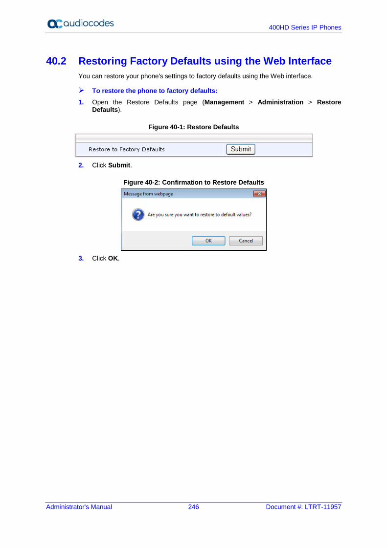
400HD Series IP Phones
Administrator's Manual 246 Document #: LTRT-11957
40.2 Restoring Factory Defaults using the Web Interface You can restore your phone's settings to factory defaults using the Web interface.
To restore the phone to factory defaults: 1. Open the Restore Defaults page (Management > Administration > Restore
Defaults).
Figure 40-1: Restore Defaults
2. Click Submit.
Figure 40-2: Confirmation to Restore Defaults
3. Click OK.
Part IX Status and Monitoring

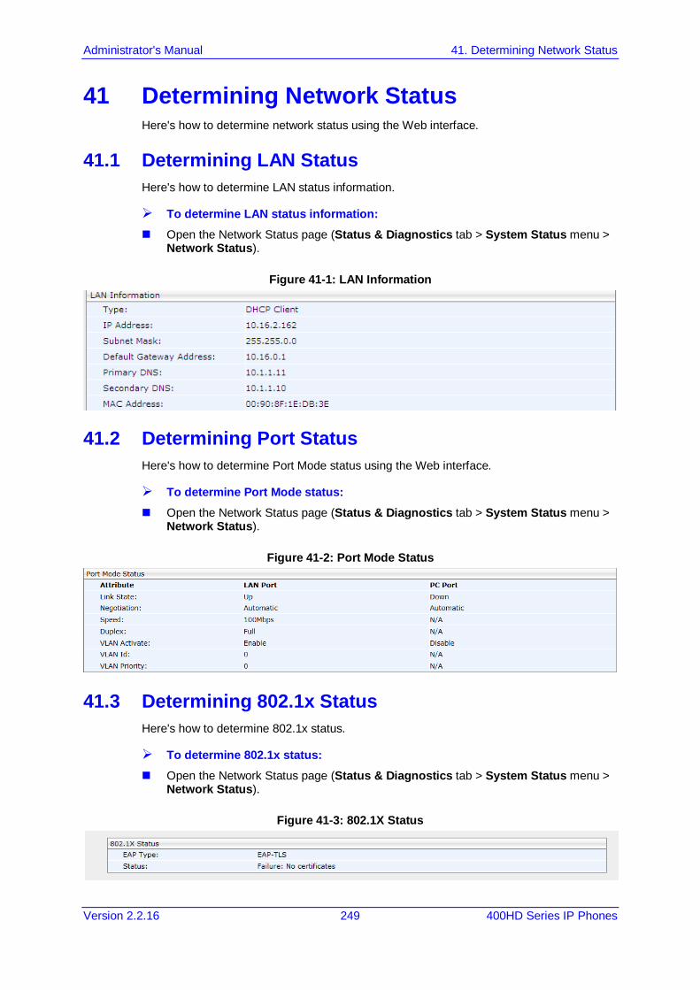
Administrator's Manual 41. Determining Network Status
Version 2.2.16 249 400HD Series IP Phones
41 Determining Network Status Here's how to determine network status using the Web interface.
41.1 Determining LAN Status Here's how to determine LAN status information.
To determine LAN status information: Open the Network Status page (Status & Diagnostics tab > System Status menu >
Network Status).
Figure 41-1: LAN Information
41.2 Determining Port Status Here's how to determine Port Mode status using the Web interface.
To determine Port Mode status: Open the Network Status page (Status & Diagnostics tab > System Status menu >
Network Status).
Figure 41-2: Port Mode Status
41.3 Determining 802.1x Status Here's how to determine 802.1x status.
To determine 802.1x status: Open the Network Status page (Status & Diagnostics tab > System Status menu >
Network Status).
Figure 41-3: 802.1X Status

400HD Series IP Phones
Administrator's Manual 250 Document #: LTRT-11957
This page is intentionally left blank.

Administrator's Manual 42. Determining VoIP Status
Version 2.2.16 251 400HD Series IP Phones
42 Determining VoIP Status Here's how to determine VoIP status using the Web interface.
42.1 Determining Phone Status Here's how to determine phone status.
To determine phone status: Open the VoIP Status page (Status & Diagnostics tab > System Status menu > VoIP
Status).
Figure 42-1: VoIP Status - Phone Status
42.2 Determining Line Status Here's how to determine line status.
To determine line status: Open the Network Status page (Status & Diagnostics tab > System Status menu >
VoIP Status).
Figure 42-2: Line Status
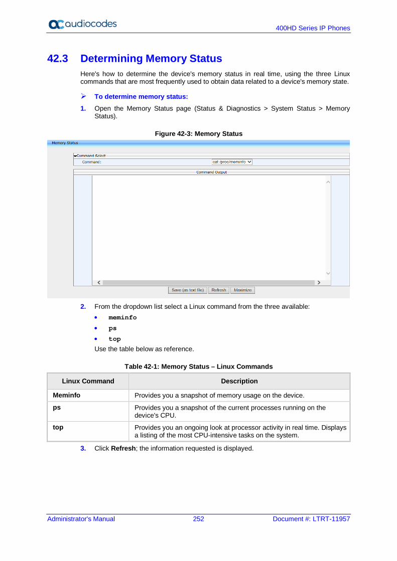
400HD Series IP Phones
Administrator's Manual 252 Document #: LTRT-11957
42.3 Determining Memory Status Here's how to determine the device's memory status in real time, using the three Linux commands that are most frequently used to obtain data related to a device's memory state.
To determine memory status: 1. Open the Memory Status page (Status & Diagnostics > System Status > Memory
Status).
Figure 42-3: Memory Status
2. From the dropdown list select a Linux command from the three available:
• meminfo
• ps
• top
Use the table below as reference.
Table 42-1: Memory Status – Linux Commands
Linux Command Description
Meminfo Provides you a snapshot of memory usage on the device.
ps Provides you a snapshot of the current processes running on the device's CPU.
top Provides you an ongoing look at processor activity in real time. Displays a listing of the most CPU-intensive tasks on the system.
3. Click Refresh; the information requested is displayed.
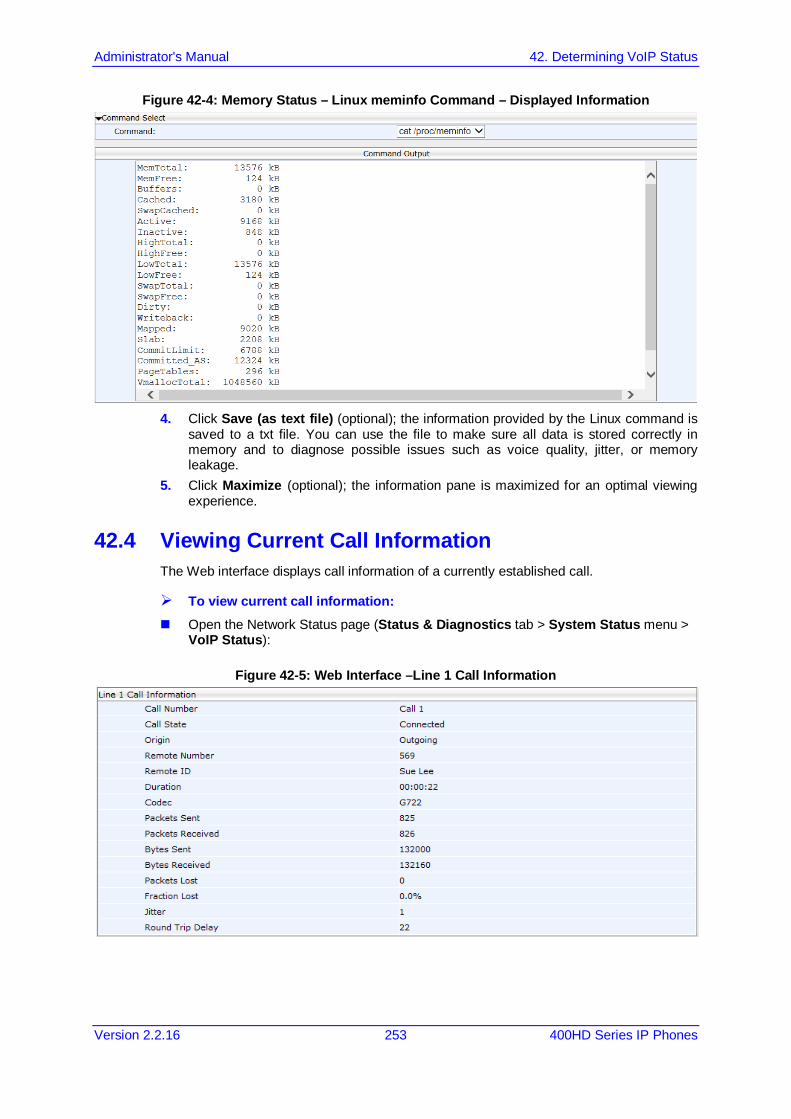
Administrator's Manual 42. Determining VoIP Status
Version 2.2.16 253 400HD Series IP Phones
Figure 42-4: Memory Status – Linux meminfo Command – Displayed Information
4. Click Save (as text file) (optional); the information provided by the Linux command is
saved to a txt file. You can use the file to make sure all data is stored correctly in memory and to diagnose possible issues such as voice quality, jitter, or memory leakage.
5. Click Maximize (optional); the information pane is maximized for an optimal viewing experience.
42.4 Viewing Current Call Information The Web interface displays call information of a currently established call.
To view current call information: Open the Network Status page (Status & Diagnostics tab > System Status menu >
VoIP Status):
Figure 42-5: Web Interface –Line 1 Call Information

400HD Series IP Phones
Administrator's Manual 254 Document #: LTRT-11957
This page is intentionally left blank.
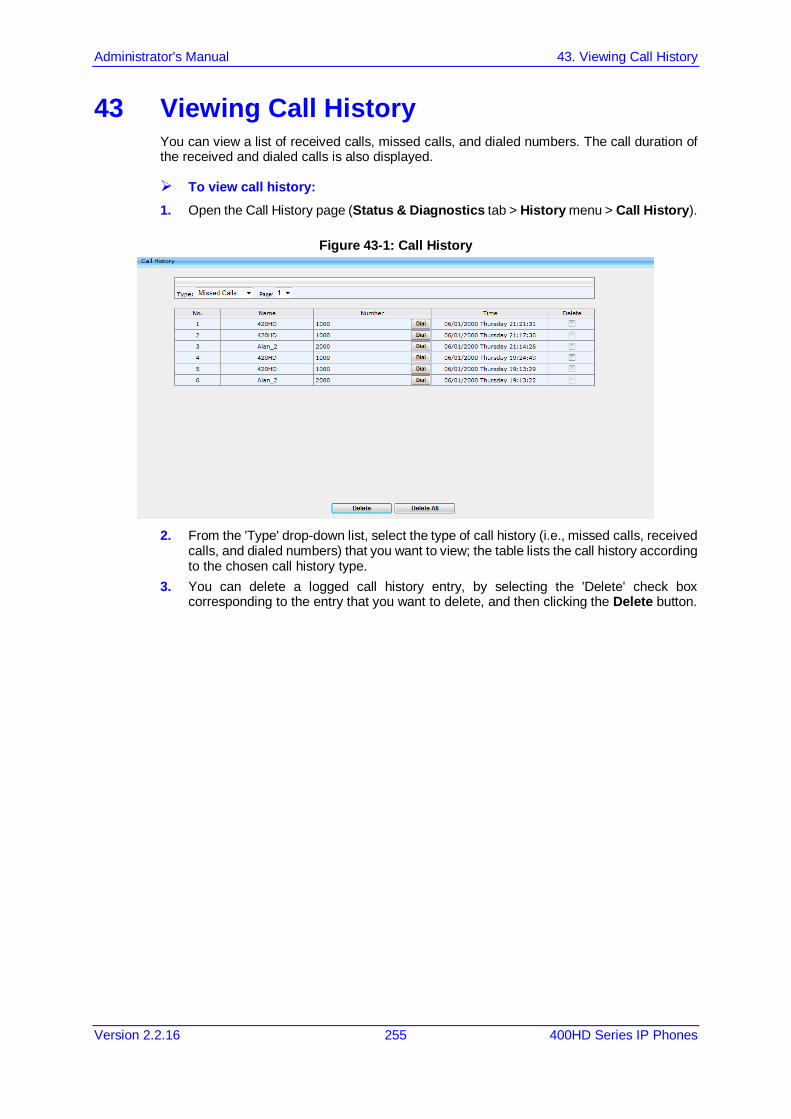
Administrator's Manual 43. Viewing Call History
Version 2.2.16 255 400HD Series IP Phones
43 Viewing Call History You can view a list of received calls, missed calls, and dialed numbers. The call duration of the received and dialed calls is also displayed.
To view call history: 1. Open the Call History page (Status & Diagnostics tab > History menu > Call History).
Figure 43-1: Call History
2. From the 'Type' drop-down list, select the type of call history (i.e., missed calls, received
calls, and dialed numbers) that you want to view; the table lists the call history according to the chosen call history type.
3. You can delete a logged call history entry, by selecting the 'Delete' check box corresponding to the entry that you want to delete, and then clicking the Delete button.

400HD Series IP Phones
Administrator's Manual 256 Document #: LTRT-11957
This page is intentionally left blank.

Administrator's Manual 44. Accessing System Information
Version 2.2.16 257 400HD Series IP Phones
44 Accessing System Information 44.1 Accessing Phone Firmware Version
You can determine the phone firmware version using the Web interface or from the phone screen.
44.1.1 Accessing Firmware Version using the Web Interface You can determine the firmware version currently running on the phone.
To view the phone's firmware version: Open the System Information page (Status & Diagnostics tab > System Information
menu > General).
Figure 44-1: System Information–Firmware Version
44.1.2 Accessing Firmware Version from the Phone's Screen Here's how to determine firmware version on the phone.
To determine the phone's firmware version from the screen: On the phone, open the Firmware Version screen (MENU key > Status > Firmware
Version):
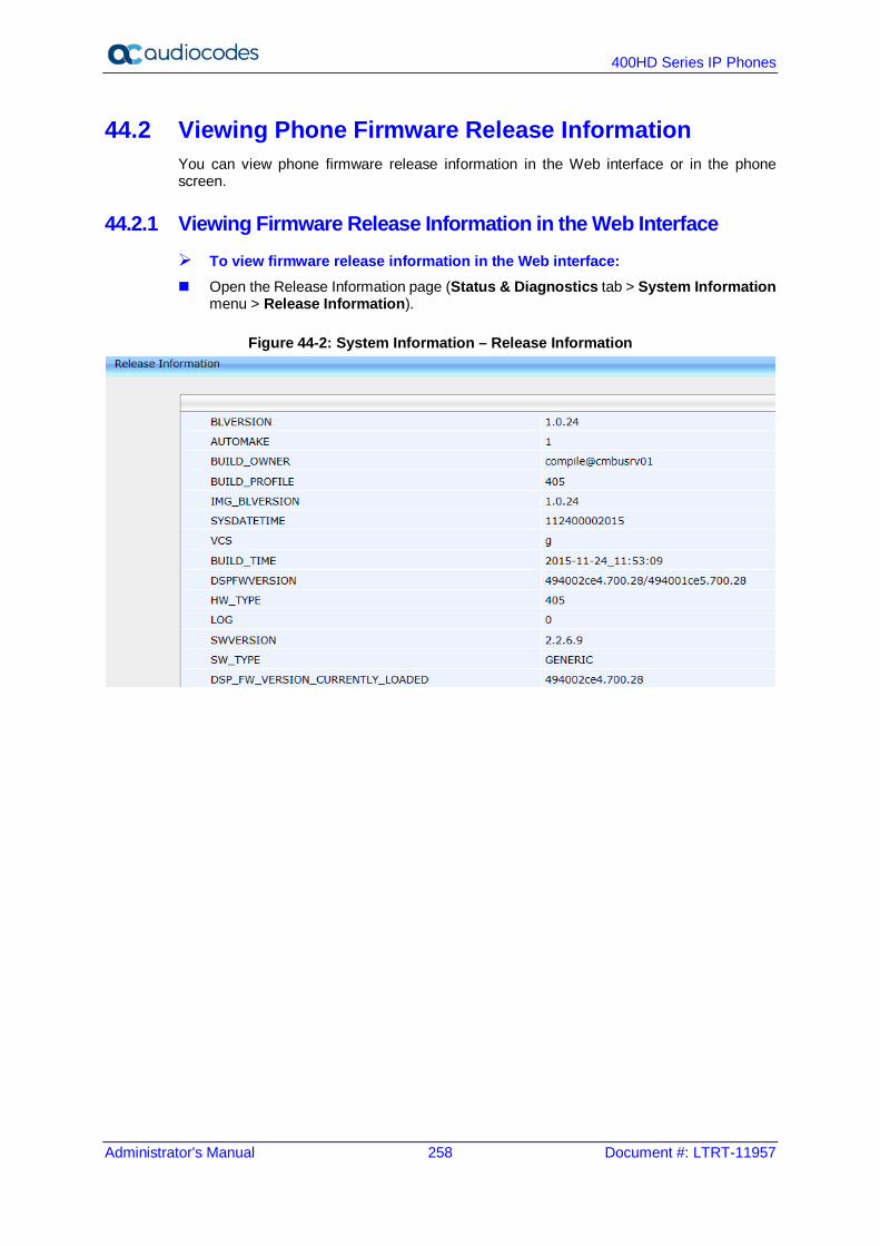
400HD Series IP Phones
Administrator's Manual 258 Document #: LTRT-11957
44.2 Viewing Phone Firmware Release Information You can view phone firmware release information in the Web interface or in the phone screen.
44.2.1 Viewing Firmware Release Information in the Web Interface To view firmware release information in the Web interface: Open the Release Information page (Status & Diagnostics tab > System Information
menu > Release Information).
Figure 44-2: System Information – Release Information
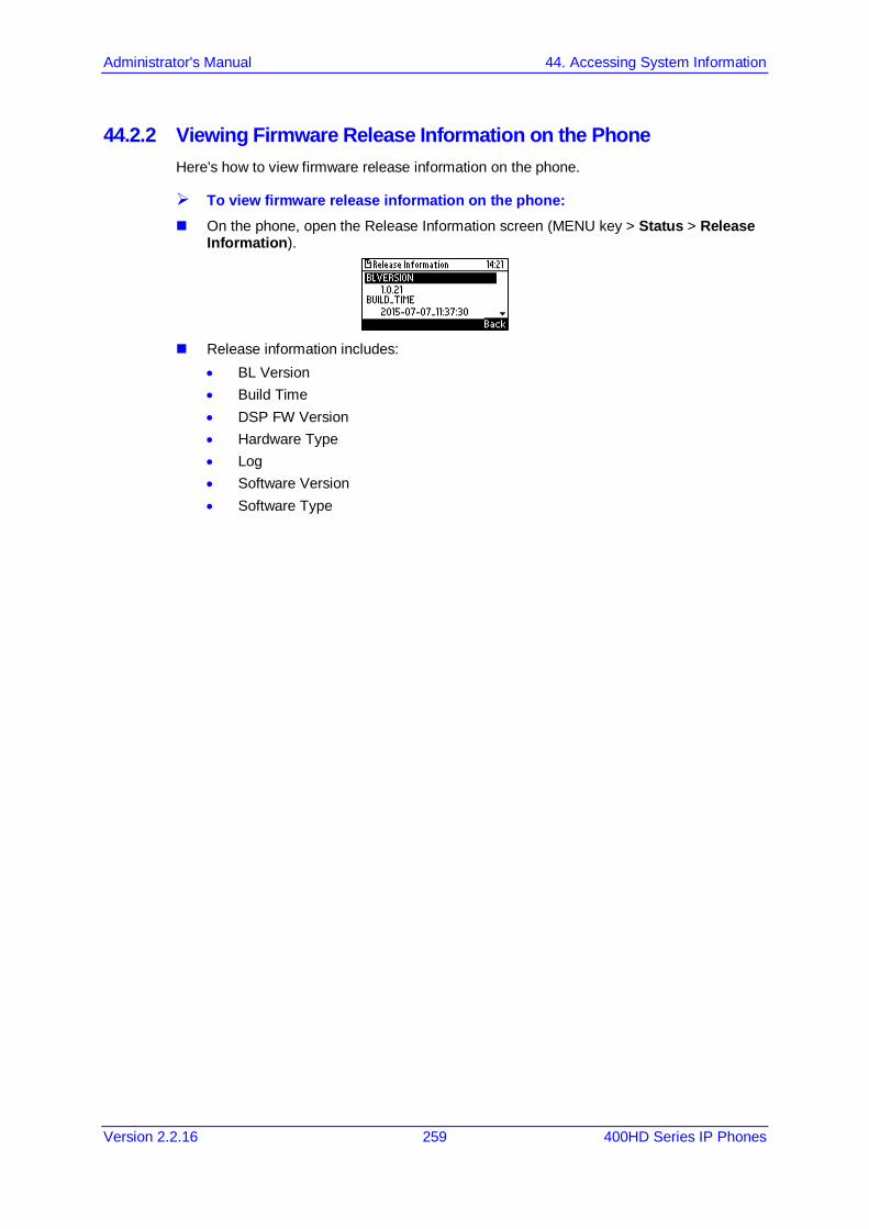
Administrator's Manual 44. Accessing System Information
Version 2.2.16 259 400HD Series IP Phones
44.2.2 Viewing Firmware Release Information on the Phone Here's how to view firmware release information on the phone.
To view firmware release information on the phone: On the phone, open the Release Information screen (MENU key > Status > Release
Information).
Release information includes:
• BL Version • Build Time • DSP FW Version • Hardware Type • Log • Software Version • Software Type

400HD Series IP Phones
Administrator's Manual 260 Document #: LTRT-11957
This page is intentionally left blank.
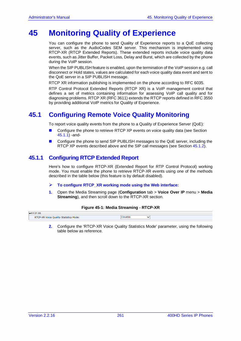
Administrator's Manual 45. Monitoring Quality of Experience
Version 2.2.16 261 400HD Series IP Phones
45 Monitoring Quality of Experience You can configure the phone to send Quality of Experience reports to a QoE collecting server, such as the AudioCodes SEM server. This mechanism is implemented using RTCP-XR (RTCP Extended Reports). These extended reports include voice quality data events, such as Jitter Buffer, Packet Loss, Delay and Burst, which are collected by the phone during the VoIP session. When the SIP PUBLISH feature is enabled, upon the termination of the VoIP session e.g. call disconnect or Hold states, values are calculated for each voice quality data event and sent to the QoE server in a SIP PUBLISH message. RTCP XR information publishing is implemented on the phone according to RFC 6035. RTP Control Protocol Extended Reports (RTCP XR) is a VoIP management control that defines a set of metrics containing information for assessing VoIP call quality and for diagnosing problems. RTCP XR (RFC 3611) extends the RTCP reports defined in RFC 3550 by providing additional VoIP metrics for Quality of Experience.
45.1 Configuring Remote Voice Quality Monitoring To report voice quality events from the phone to a Quality of Experience Server (QoE): Configure the phone to retrieve RTCP XP events on voice quality data (see Section
45.1.1) -and- Configure the phone to send SIP PUBLISH messages to the QoE server, including the
RTCP XP events described above and the SIP call messages (see Section 45.1.2).
45.1.1 Configuring RTCP Extended Report Here's how to configure RTCP-XR (Extended Report for RTP Control Protocol) working mode. You must enable the phone to retrieve RTCP-XR events using one of the methods described in the table below (this feature is by default disabled).
To configure RTCP_XR working mode using the Web interface: 1. Open the Media Streaming page (Configuration tab > Voice Over IP menu > Media
Streaming), and then scroll down to the RTCP-XR section.
Figure 45-1: Media Streaming - RTCP-XR
2. Configure the 'RTCP-XR Voice Quality Statistics Mode' parameter, using the following
table below as reference.
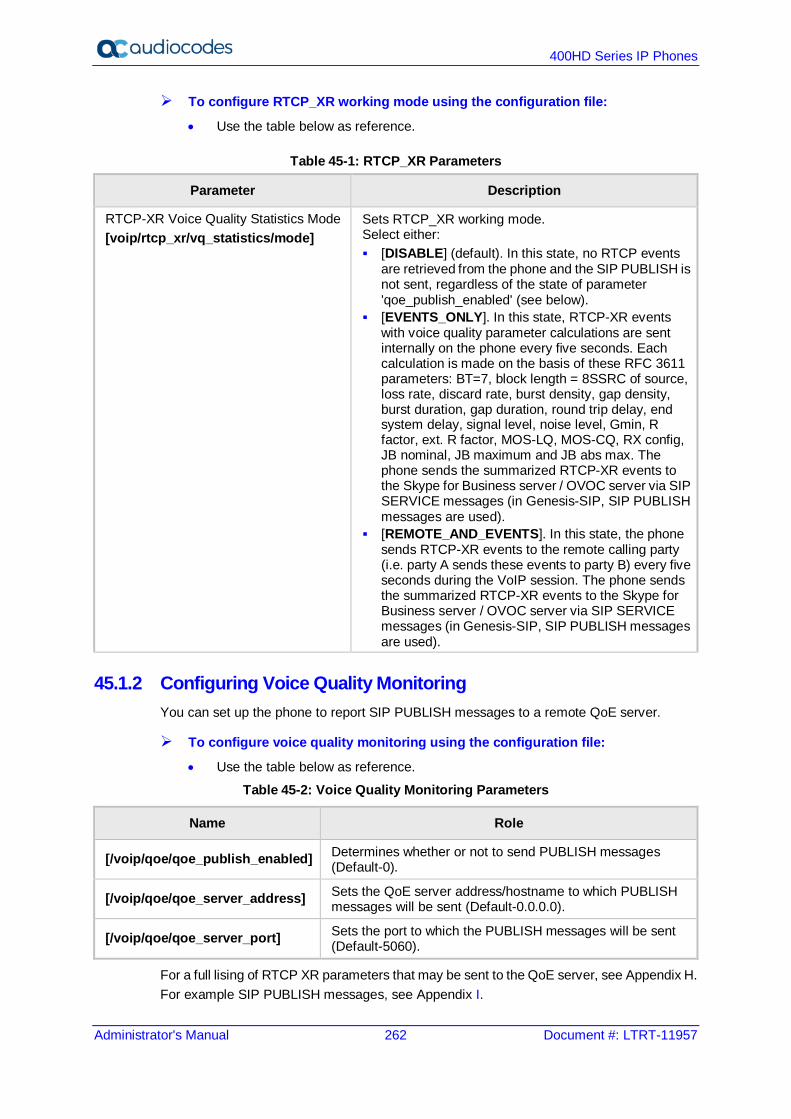
400HD Series IP Phones
Administrator's Manual 262 Document #: LTRT-11957
To configure RTCP_XR working mode using the configuration file:
• Use the table below as reference.
Table 45-1: RTCP_XR Parameters
Parameter Description
RTCP-XR Voice Quality Statistics Mode [voip/rtcp_xr/vq_statistics/mode]
Sets RTCP_XR working mode. Select either: [DISABLE] (default). In this state, no RTCP events
are retrieved from the phone and the SIP PUBLISH is not sent, regardless of the state of parameter 'qoe_publish_enabled' (see below).
[EVENTS_ONLY]. In this state, RTCP-XR events with voice quality parameter calculations are sent internally on the phone every five seconds. Each calculation is made on the basis of these RFC 3611 parameters: BT=7, block length = 8SSRC of source, loss rate, discard rate, burst density, gap density, burst duration, gap duration, round trip delay, end system delay, signal level, noise level, Gmin, R factor, ext. R factor, MOS-LQ, MOS-CQ, RX config, JB nominal, JB maximum and JB abs max. The phone sends the summarized RTCP-XR events to the Skype for Business server / OVOC server via SIP SERVICE messages (in Genesis-SIP, SIP PUBLISH messages are used).
[REMOTE_AND_EVENTS]. In this state, the phone sends RTCP-XR events to the remote calling party (i.e. party A sends these events to party B) every five seconds during the VoIP session. The phone sends the summarized RTCP-XR events to the Skype for Business server / OVOC server via SIP SERVICE messages (in Genesis-SIP, SIP PUBLISH messages are used).
45.1.2 Configuring Voice Quality Monitoring You can set up the phone to report SIP PUBLISH messages to a remote QoE server.
To configure voice quality monitoring using the configuration file:
• Use the table below as reference.
Table 45-2: Voice Quality Monitoring Parameters
Name Role
[/voip/qoe/qoe_publish_enabled] Determines whether or not to send PUBLISH messages (Default-0).
[/voip/qoe/qoe_server_address] Sets the QoE server address/hostname to which PUBLISH messages will be sent (Default-0.0.0.0).
[/voip/qoe/qoe_server_port] Sets the port to which the PUBLISH messages will be sent (Default-5060).
For a full lising of RTCP XR parameters that may be sent to the QoE server, see Appendix H. For example SIP PUBLISH messages, see Appendix I.

Part X Diagnostics and Troubleshooting

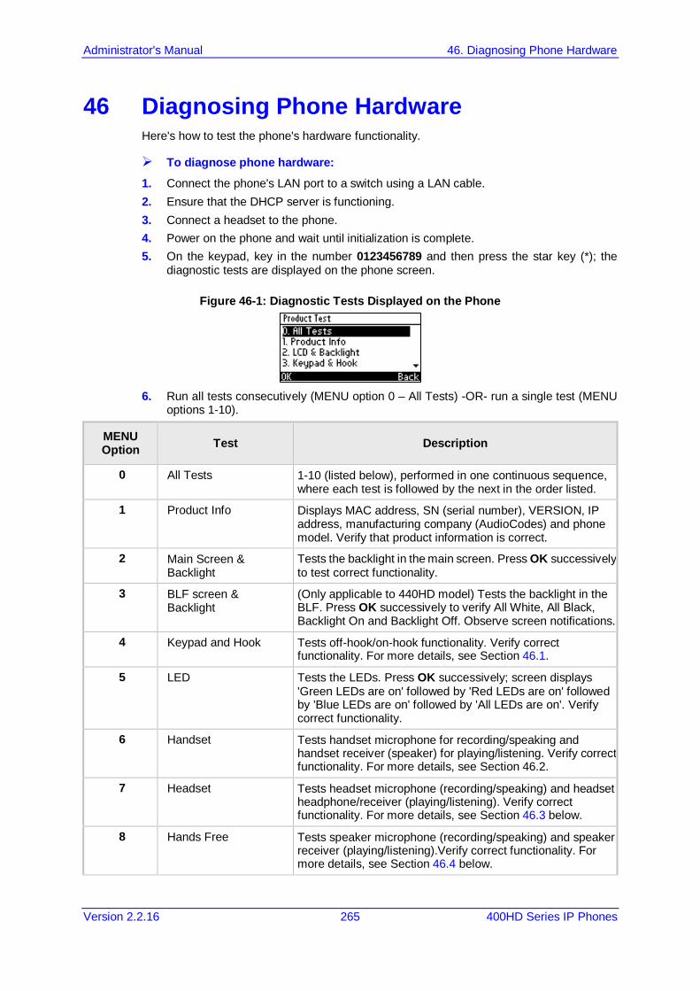
Administrator's Manual 46. Diagnosing Phone Hardware
Version 2.2.16 265 400HD Series IP Phones
46 Diagnosing Phone Hardware Here's how to test the phone's hardware functionality.
To diagnose phone hardware: 1. Connect the phone's LAN port to a switch using a LAN cable. 2. Ensure that the DHCP server is functioning. 3. Connect a headset to the phone. 4. Power on the phone and wait until initialization is complete. 5. On the keypad, key in the number 0123456789 and then press the star key (*); the
diagnostic tests are displayed on the phone screen.
Figure 46-1: Diagnostic Tests Displayed on the Phone
6. Run all tests consecutively (MENU option 0 – All Tests) -OR- run a single test (MENU
options 1-10).
MENU Option Test Description
0 All Tests 1-10 (listed below), performed in one continuous sequence, where each test is followed by the next in the order listed.
1 Product Info Displays MAC address, SN (serial number), VERSION, IP address, manufacturing company (AudioCodes) and phone model. Verify that product information is correct.
2 Main Screen & Backlight
Tests the backlight in the main screen. Press OK successively to test correct functionality.
3 BLF screen & Backlight
(Only applicable to 440HD model) Tests the backlight in the BLF. Press OK successively to verify All White, All Black, Backlight On and Backlight Off. Observe screen notifications.
4 Keypad and Hook Tests off-hook/on-hook functionality. Verify correct functionality. For more details, see Section 46.1.
5 LED Tests the LEDs. Press OK successively; screen displays 'Green LEDs are on' followed by 'Red LEDs are on' followed by 'Blue LEDs are on' followed by 'All LEDs are on'. Verify correct functionality.
6 Handset Tests handset microphone for recording/speaking and handset receiver (speaker) for playing/listening. Verify correct functionality. For more details, see Section 46.2.
7 Headset Tests headset microphone (recording/speaking) and headset headphone/receiver (playing/listening). Verify correct functionality. For more details, see Section 46.3 below.
8 Hands Free Tests speaker microphone (recording/speaking) and speaker receiver (playing/listening).Verify correct functionality. For more details, see Section 46.4 below.
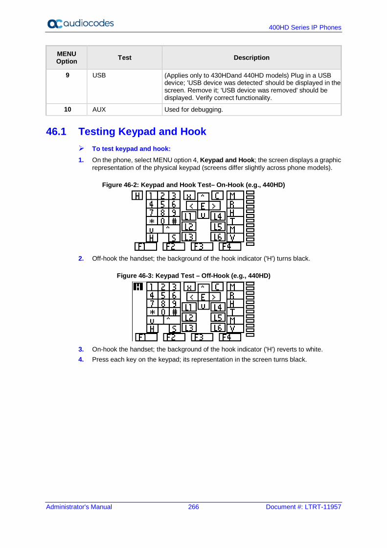
400HD Series IP Phones
Administrator's Manual 266 Document #: LTRT-11957
MENU Option Test Description
9 USB (Applies only to 430HDand 440HD models) Plug in a USB device; 'USB device was detected' should be displayed in the screen. Remove it; 'USB device was removed' should be displayed. Verify correct functionality.
10 AUX Used for debugging.
46.1 Testing Keypad and Hook To test keypad and hook: 1. On the phone, select MENU option 4, Keypad and Hook; the screen displays a graphic
representation of the physical keypad (screens differ slightly across phone models).
Figure 46-2: Keypad and Hook Test– On-Hook (e.g., 440HD)
2. Off-hook the handset; the background of the hook indicator ('H') turns black.
Figure 46-3: Keypad Test – Off-Hook (e.g., 440HD)
3. On-hook the handset; the background of the hook indicator ('H') reverts to white. 4. Press each key on the keypad; its representation in the screen turns black.

Administrator's Manual 46. Diagnosing Phone Hardware
Version 2.2.16 267 400HD Series IP Phones
46.2 Testing Handset To test the handset: 1. Select MENU option 6, Handset; the screen indicates 'Off-hook phone'. 2. Off-hook the phone; the screen indicates 'Start recording…'Speak into the handset until
the screen displays 'Start playing…' and you hear your speech playing back.
46.3 Testing the Headset To test the headset: 1. Select MENU option 7, Headset; the screen indicates 'Press any key'. 2. Press any key; the screen indicates 'Start recording…' Speak until the screen displays
'Start playing…' and you hear your speech playing back.
46.4 Testing Hands Free To test hands free: 1. Select MENU option 7, Hands Free; the phone screen indicates 'Press any key'. 2. Press any key; the phone screen indicates 'Start recording…' Speak into the phone
speaker for a few seconds until the phone screen displays 'Start playing…' and you hear your speech playing back through the speaker.

400HD Series IP Phones
Administrator's Manual 268 Document #: LTRT-11957
This page is intentionally left blank.

Administrator's Manual 47. Recovering Firmware
Version 2.2.16 269 400HD Series IP Phones
47 Recovering Firmware Here's how to recover the phone's firmware. See also Appendix C for more detailed information. If the phone is powered off for some reason during the firmware upgrade process, the phone becomes unusable. The recovery process is also available when the phone is connected to a VLAN.
To recover the phone firmware: 1. Make sure your DHCP server supports Options 66 (TFTP server address) and 67
(firmware file), and that these are configurable. 2. Before connecting the phone, verify that the TFTP server is running and the firmware
file for recovery is located in the correct location. 3. Connect your phone to the IP network, and then connect the phone to the power outlet;
a. The phone sends a TFTP request to the IP address indicated in the DHCP Option 66 field to retrieve the firmware file indicated in the DHCP Option 67 field.
b. The phone, in the DHCP Discover message sends its model name in the DHCP Option 77 field. The DHCP server, according to the phone model, sets the appropriate firmware file name in the DHCP Option 67 field sent to the phone (e.g., 440HD_2.2.2.img).
c. The phone then upgrades to the recovery firmware. d. After the firmware upgrade process completes, the phone boots up successfully.

400HD Series IP Phones
Administrator's Manual 270 Document #: LTRT-11957
This page is intentionally left blank.

Administrator's Manual 48. Configuring System Logging (Syslog)
Version 2.2.16 271 400HD Series IP Phones
48 Configuring System Logging (Syslog) System logging (Syslog) can be configured using the Web interface or configuration file. Two Syslog options are available: Regular Syslog (see the next section) Lightweight Syslog (see Section 48.1.2).
48.1.1 Analyzing and Debugging Traffic using Regular Syslog The System Logging (Syslog) feature is used for traffic analysis and debugging. The feature can be configured using the Web interface or configuration file.
To configure system logging using the Web interface: 1. Open the System Logging page (Status & Diagnostics > Diagnostics > Logging).
Figure 48-1: Web Interface –System Logging
2. Configure using the table below as reference.
To configure system logging using the configuration file:
• Use the table below as reference.
Table 48-1: Syslog Parameters
Parameter Description
Activate [system/syslog/mode]
Enables Syslog. Possible values are: • Disable = No Syslog. • Network = Syslog is sent to the Syslog server.
(Recommended). • Console = Syslog is sent to the phone console.
(You need to connect a serial cable to view the logs. This causes delays in phone operation).
• Both = Syslog sends to the Syslog server and to the console.
Note: It is recommended to leave this parameter at its default value.
Server IP Address or Host Name [system/syslog/server_address]
The IP address (in dotted-decimal notation) of the computer you are using to run the Syslog server (e.g.,
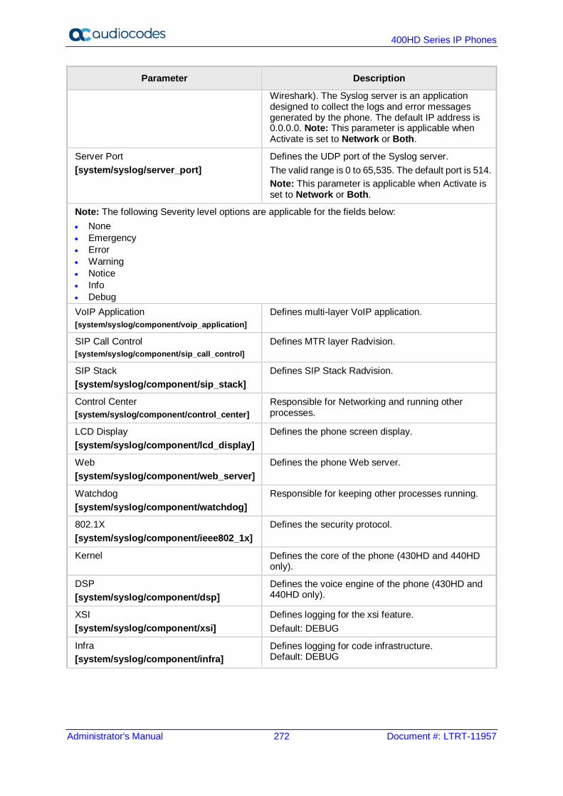
400HD Series IP Phones
Administrator's Manual 272 Document #: LTRT-11957
Parameter Description
Wireshark). The Syslog server is an application designed to collect the logs and error messages generated by the phone. The default IP address is 0.0.0.0. Note: This parameter is applicable when Activate is set to Network or Both.
Server Port [system/syslog/server_port]
Defines the UDP port of the Syslog server. The valid range is 0 to 65,535. The default port is 514. Note: This parameter is applicable when Activate is set to Network or Both.
Note: The following Severity level options are applicable for the fields below: • None • Emergency • Error • Warning • Notice • Info • Debug VoIP Application [system/syslog/component/voip_application]
Defines multi-layer VoIP application.
SIP Call Control [system/syslog/component/sip_call_control]
Defines MTR layer Radvision.
SIP Stack [system/syslog/component/sip_stack]
Defines SIP Stack Radvision.
Control Center [system/syslog/component/control_center]
Responsible for Networking and running other processes.
LCD Display [system/syslog/component/lcd_display]
Defines the phone screen display.
Web [system/syslog/component/web_server]
Defines the phone Web server.
Watchdog [system/syslog/component/watchdog]
Responsible for keeping other processes running.
802.1X [system/syslog/component/ieee802_1x]
Defines the security protocol.
Kernel Defines the core of the phone (430HD and 440HD only).
DSP [system/syslog/component/dsp]
Defines the voice engine of the phone (430HD and 440HD only).
XSI [system/syslog/component/xsi]
Defines logging for the xsi feature. Default: DEBUG
Infra [system/syslog/component/infra]
Defines logging for code infrastructure. Default: DEBUG
Administrator's Manual 48. Configuring System Logging (Syslog)
Version 2.2.16 273 400HD Series IP Phones
48.1.2 Analyzing and Debugging Traffic using 'Lightweight Syslog' A 'Lightweight Syslog' logging mechanism allows you to perform phone logging without affecting phone performance.
To enable the Lightweight Syslog: In the Web interface, open the phone's System Logging page (Status & Diagnostics
tab > Diagnostics > Logging), set the 'Activate' parameter to Network and provide a valid IP address and server port. Do not set any of the options (keep all as None).

400HD Series IP Phones
Administrator's Manual 274 Document #: LTRT-11957
This page is intentionally left blank.

Administrator's Manual 49. Viewing Error Messages Displayed in the Phone Screen
Version 2.2.16 275 400HD Series IP Phones
49 Viewing Error Messages Displayed in the Phone Screen The table below shows the error messages that may be viewed on the phone.
Table 49-1: Error Messages Displayed in the Phone Screen
Message Description
LAN Link failure The LAN link is disconnected.
Registration failure Received error or no response from the SIP proxy
Note:
• With both errors, the 'ringer' LED remains red until the error is fixed. • While the error message is displayed, the user can`t dial or initiate a call.

400HD Series IP Phones
Administrator's Manual 276 Document #: LTRT-11957
This page is intentionally left blank.
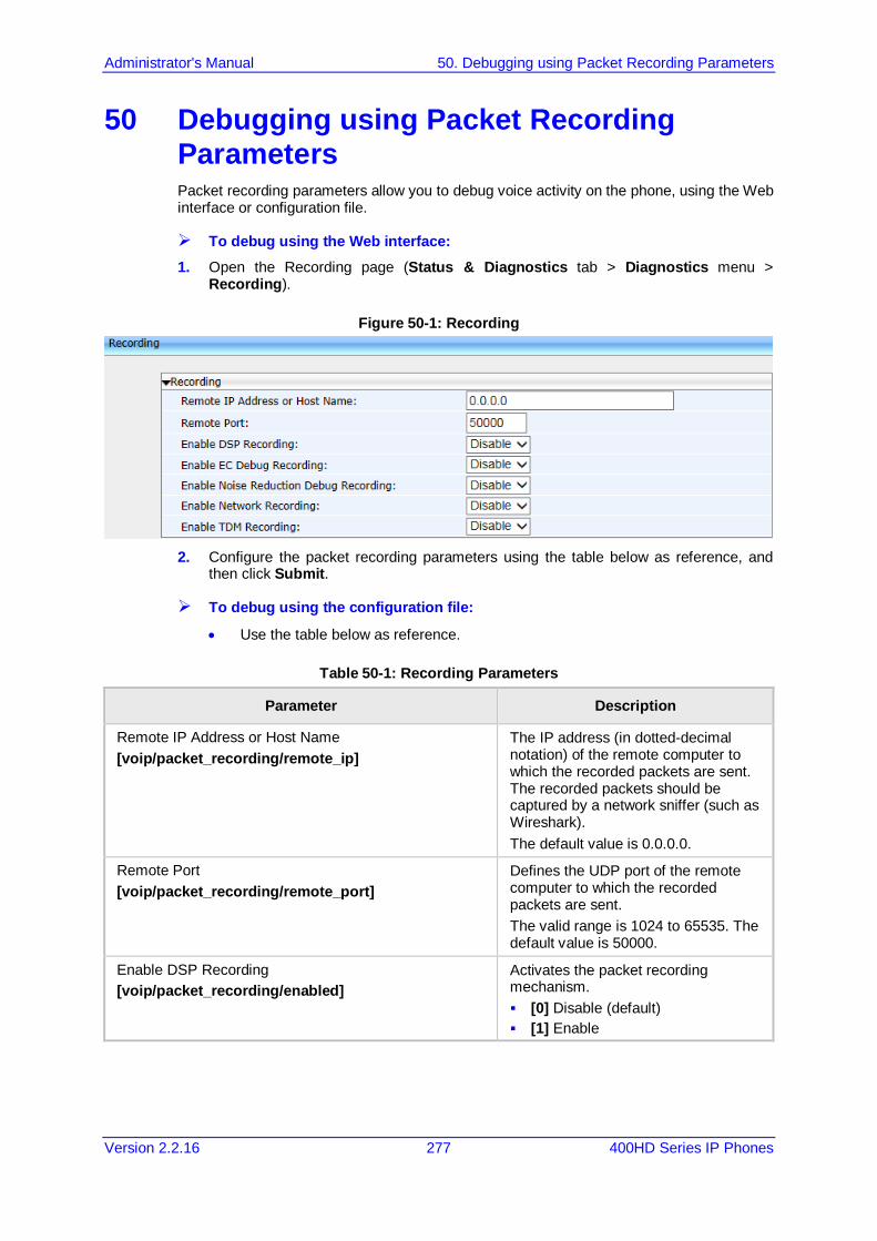
Administrator's Manual 50. Debugging using Packet Recording Parameters
Version 2.2.16 277 400HD Series IP Phones
50 Debugging using Packet Recording Parameters Packet recording parameters allow you to debug voice activity on the phone, using the Web interface or configuration file.
To debug using the Web interface: 1. Open the Recording page (Status & Diagnostics tab > Diagnostics menu >
Recording).
Figure 50-1: Recording
2. Configure the packet recording parameters using the table below as reference, and
then click Submit.
To debug using the configuration file:
• Use the table below as reference.
Table 50-1: Recording Parameters
Parameter Description
Remote IP Address or Host Name [voip/packet_recording/remote_ip]
The IP address (in dotted-decimal notation) of the remote computer to which the recorded packets are sent. The recorded packets should be captured by a network sniffer (such as Wireshark). The default value is 0.0.0.0.
Remote Port [voip/packet_recording/remote_port]
Defines the UDP port of the remote computer to which the recorded packets are sent. The valid range is 1024 to 65535. The default value is 50000.
Enable DSP Recording [voip/packet_recording/enabled]
Activates the packet recording mechanism. [0] Disable (default) [1] Enable
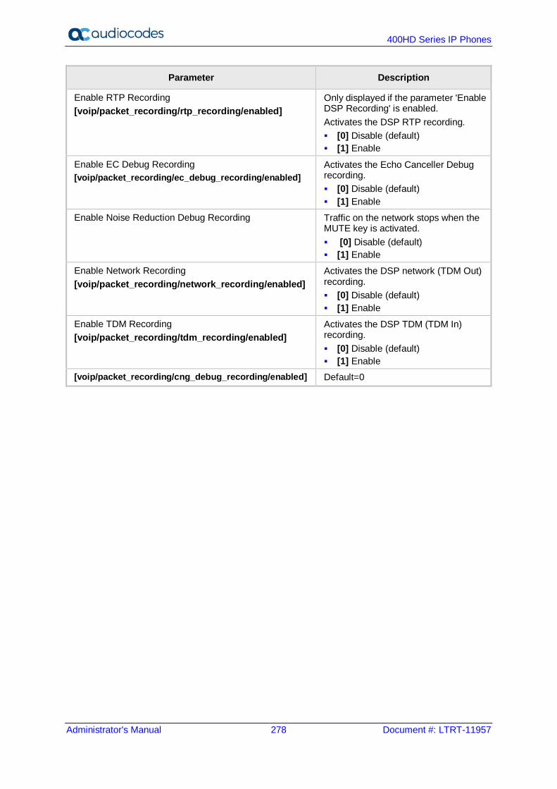
400HD Series IP Phones
Administrator's Manual 278 Document #: LTRT-11957
Parameter Description
Enable RTP Recording [voip/packet_recording/rtp_recording/enabled]
Only displayed if the parameter 'Enable DSP Recording' is enabled. Activates the DSP RTP recording. [0] Disable (default) [1] Enable
Enable EC Debug Recording [voip/packet_recording/ec_debug_recording/enabled]
Activates the Echo Canceller Debug recording. [0] Disable (default) [1] Enable
Enable Noise Reduction Debug Recording Traffic on the network stops when the MUTE key is activated. [0] Disable (default) [1] Enable
Enable Network Recording [voip/packet_recording/network_recording/enabled]
Activates the DSP network (TDM Out) recording. [0] Disable (default) [1] Enable
Enable TDM Recording [voip/packet_recording/tdm_recording/enabled]
Activates the DSP TDM (TDM In) recording. [0] Disable (default) [1] Enable
[voip/packet_recording/cng_debug_recording/enabled] Default=0

Administrator's Manual 51. Creating a Crash Dump File
Version 2.2.16 279 400HD Series IP Phones
51 Creating a Crash Dump File Here's how to create a crash dump file using the Web interface. Crash dump copies historical processes to a file. The file is created at the time the problem occurs. You must send it to AudioCodes Customer Technical Support for troubleshooting.
To download a crash dump file using the Web interface: 1. Open the Crash Dump page (Status & Diagnostics tab > Diagnostics menu > Crash
Dump).
Figure 51-1: Crash Dump
Table 51-1: Crash Dump Parameters
Parameter Description
Total tombstones The number of crashes on the phone.
Last tombstone The date and time of the last crash (the exact time of the crash).
2. Click Download to save the crash dump file on your computer.

400HD Series IP Phones
Administrator's Manual 280 Document #: LTRT-11957
This page is intentionally left blank.
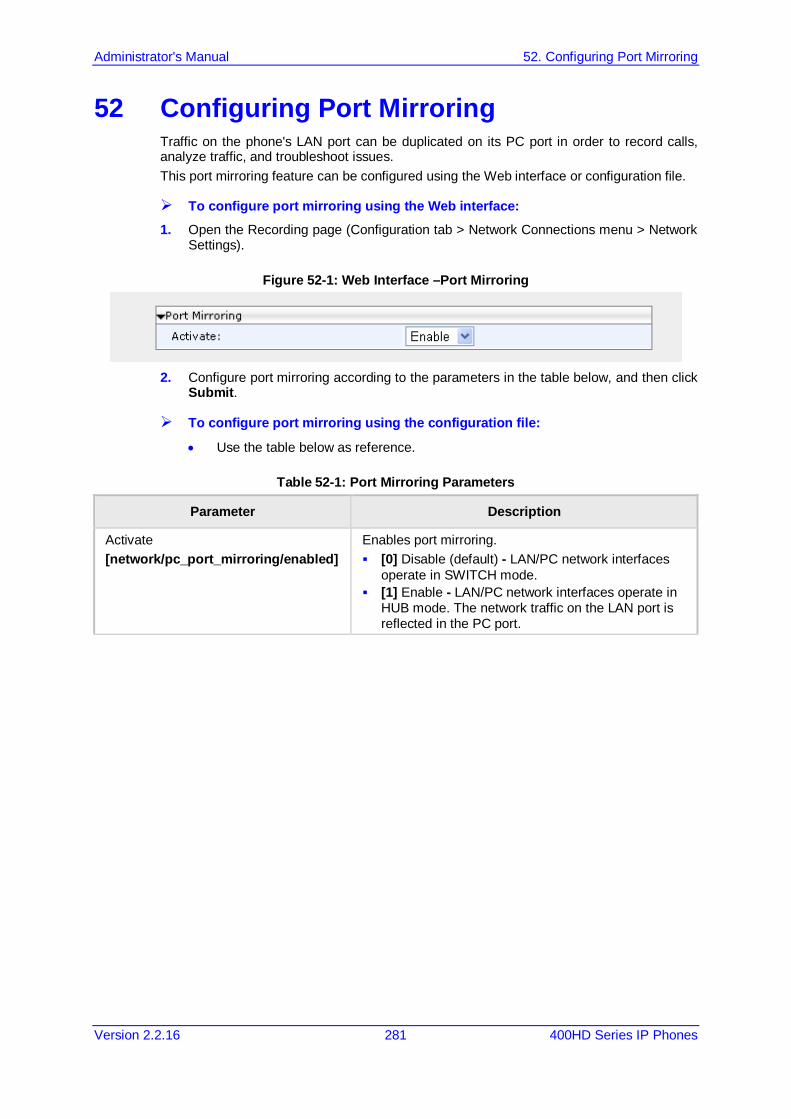
Administrator's Manual 52. Configuring Port Mirroring
Version 2.2.16 281 400HD Series IP Phones
52 Configuring Port Mirroring Traffic on the phone's LAN port can be duplicated on its PC port in order to record calls, analyze traffic, and troubleshoot issues. This port mirroring feature can be configured using the Web interface or configuration file.
To configure port mirroring using the Web interface: 1. Open the Recording page (Configuration tab > Network Connections menu > Network
Settings).
Figure 52-1: Web Interface –Port Mirroring
2. Configure port mirroring according to the parameters in the table below, and then click
Submit.
To configure port mirroring using the configuration file:
• Use the table below as reference.
Table 52-1: Port Mirroring Parameters
Parameter Description
Activate [network/pc_port_mirroring/enabled]
Enables port mirroring. [0] Disable (default) - LAN/PC network interfaces
operate in SWITCH mode. [1] Enable - LAN/PC network interfaces operate in
HUB mode. The network traffic on the LAN port is reflected in the PC port.

400HD Series IP Phones
Administrator's Manual 282 Document #: LTRT-11957
This page is intentionally left blank.

Administrator's Manual 53. Enabling Tracing
Version 2.2.16 283 400HD Series IP Phones
53 Enabling Tracing Here's how to set up the phone to store trace messages. You can then send the saved logged trace to AudioCodes Customer Technical Support for effective troubleshooting and diagnosis.
Note:
• During regular phone operation it's advisable to disable debug tracing for improved performance.
• It's advisable to enable debug tracing only if bugs are encountered and AudioCodes asks you to provide tracing logs.
To enable tracing: 1. In the Web interface, open the Tracing System Key Behavior page (Status &
Diagnostics tab > Diagnostics > Tracing).
Figure 53-1: Tracing System Key Behavior
2. Set the 'Max File Size' field to 1024 (see the table below). 3. Set the 'Trace Level' field to Debug to activate tracing to debug level, and then click
Submit (see the table below). 4. Click Clean log, and then power up the phone. 5. To save the log file to your computer, click Save log. 6. Send the saved logged trace to AudioCodes Customer Technical Support for
troubleshooting.

400HD Series IP Phones
Administrator's Manual 284 Document #: LTRT-11957
To configure tracing using the configuration file:
• Use the table below as reference.
Table 53-1: Tracing Parameters
Parameter Description
[system/trace/console_printf/enabled] Enables / disables console print. [0] Disable (default) – Disables console print. [1] Enable - Enables console print.
Trace Level [system/trace/level]
During regular phone operation it's advisable to disable debug tracing for improved performance. It's advisable to enable debug tracing only if bugs are encountered and AudioCodes asks you to provide tracing logs, in which case set this parameter to Debug. Valid values are: None (default) Emergency Error Warning Notice Info Debug
Max File Size [system/trace/max_file_size]
Set to 1024 Default: 200
Part XI Appendices


Administrator's Manual A. Configuring Phones in Server-Specific Deployments
Version 2.2.16 287 400HD Series IP Phones
A Configuring Phones in Server-Specific Deployments This appendix shows how to configure phones in server-specific deployments.
A.1 BroadSoft's BroadWorks Features supported in a BroadSoft environment are:
Table A-1: Features Supported in a BroadSoft Environment
Feature 420HD 430HD 440HD
BSFT DMS for provisioning √ √ √
BLF Support X √ √
Call FWD √ √ √
Call Transfer √ √ √
Call Park √ √ √
Call hold √ √ √
Dial Plan √ √ √
Caller ID √ √ √
Message Waiting Indication √ √ √
Local 3-Way Conference √ √ √
DND √ √ √
Feature key Sync √ √ √
Network Conference √ √ √
Shared Call Appearance X √ √
Broadworks Phone book support √ √ √
Voice Message Support √ √ √
DNS SRV Lookup for Redundancy and register failover √ √ √
ACD (Automatic Call Distribution) √

400HD Series IP Phones
Administrator's Manual 288 Document #: LTRT-11957
A.1.1 Configuring BLF Configuration of the BLF feature is unique when the selected application server is BroadSoft's BroadWorks application platform.
Note: This section only applies to 430HD and 440HD phones.
To configure BLF in a BroadSoft environment: 1. Open the Services page (Configuration tab > Voice Over IP menu > Services).
Figure A-1: BLF Configuration in a BroadSoft Environment
2. From the 'Application Server Type' drop-down list, select BSFT. 3. Under BLF Support do this:
a. From the 'Activate' drop-down (voip/services/busy_lamp_field/enabled parameter), select Enable.
b. In the 'BLF Subscription Period' field (voip/services/busy_lamp_field/subscription_period parameter), enter the interval between BLF and SIP SUBSCRIBE messages.
c. In the 'User Resource List' field (voip/services/busy_lamp_field/Uri parameter), enter the resource list URI to which the phone can subscribe to in order to get the BLF information from the application server.
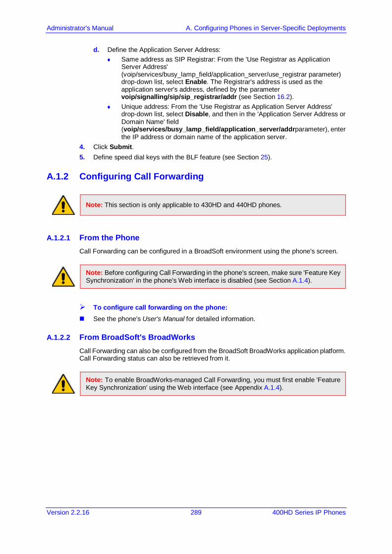
Administrator's Manual A. Configuring Phones in Server-Specific Deployments
Version 2.2.16 289 400HD Series IP Phones
d. Define the Application Server Address: ♦ Same address as SIP Registrar: From the 'Use Registrar as Application
Server Address' (voip/services/busy_lamp_field/application_server/use_registrar parameter) drop-down list, select Enable. The Registrar's address is used as the application server's address, defined by the parameter voip/signalling/sip/sip_registrar/addr (see Section 16.2).
♦ Unique address: From the 'Use Registrar as Application Server Address' drop-down list, select Disable, and then in the 'Application Server Address or Domain Name' field (voip/services/busy_lamp_field/application_server/addrparameter), enter the IP address or domain name of the application server.
4. Click Submit. 5. Define speed dial keys with the BLF feature (see Section 25).
A.1.2 Configuring Call Forwarding
Note: This section is only applicable to 430HD and 440HD phones.
A.1.2.1 From the Phone Call Forwarding can be configured in a BroadSoft environment using the phone's screen.
Note: Before configuring Call Forwarding in the phone's screen, make sure 'Feature Key Synchronization' in the phone's Web interface is disabled (see Section A.1.4).
To configure call forwarding on the phone: See the phone's User's Manual for detailed information.
A.1.2.2 From BroadSoft's BroadWorks Call Forwarding can also be configured from the BroadSoft BroadWorks application platform. Call Forwarding status can also be retrieved from it.
Note: To enable BroadWorks-managed Call Forwarding, you must first enable 'Feature Key Synchronization' using the Web interface (see Appendix A.1.4).

400HD Series IP Phones
Administrator's Manual 290 Document #: LTRT-11957
The figure below shows Call Forwarding configuration and status in BroadSoft's BroadWorks.
Figure A-2: Configuring Call Forwarding using BroadSoft's BroadWorks
Note: The 'Forward No Reply' timeout can be configured as 'number of rings' rather than as 'seconds' if the BroadSoft Feature Key is enabled (by configuring the cfg file parameter 'voip/line/0/call_forward/timeout_mode' to RINGS_COUNT instead of to the default SECONDS). For example, if the BroadSoft Feature Key is enabled and 'voip/line/0/call_forward/timeout_mode' is configured to RINGS_COUNT, the phone will by default ring 2r (2 rings) before the call is forwarded. The setting can be changed according to user preference to 4r (4 rings), for example. The feature allows compliance with BroadSoft's Feature Key Synchronization method.
For detailed information, see related BroadSoft documention.
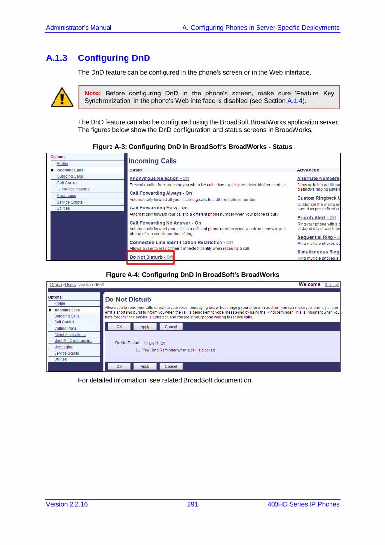
Administrator's Manual A. Configuring Phones in Server-Specific Deployments
Version 2.2.16 291 400HD Series IP Phones
A.1.3 Configuring DnD The DnD feature can be configured in the phone's screen or in the Web interface.
Note: Before configuring DnD in the phone's screen, make sure 'Feature Key Synchronization' in the phone's Web interface is disabled (see Section A.1.4).
The DnD feature can also be configured using the BroadSoft BroadWorks application server. The figures below show the DnD configuration and status screens in BroadWorks.
Figure A-3: Configuring DnD in BroadSoft's BroadWorks - Status
Figure A-4: Configuring DnD in BroadSoft's BroadWorks
For detailed information, see related BroadSoft documention.
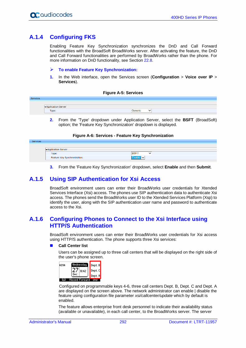
400HD Series IP Phones
Administrator's Manual 292 Document #: LTRT-11957
A.1.4 Configuring FKS Enabling Feature Key Synchronization synchronizes the DnD and Call Forward functionalities with the BroadSoft BroadWorks server. After activating the feature, the DnD and Call Forward functionalities are performed by BroadWorks rather than the phone. For more information on DnD functionality, see Section 22.8.
To enable Feature Key Synchronization: 1. In the Web interface, open the Services screen (Configuration > Voice over IP >
Services).
Figure A-5: Services
2. From the 'Type' dropdown under Application Server, select the BSFT (BroadSoft)
option; the 'Feature Key Synchronization' dropdown is displayed.
Figure A-6: Services - Feature Key Synchronization
3. From the 'Feature Key Synchronization' dropdown, select Enable and then Submit.
A.1.5 Using SIP Authentication for Xsi Access BroadSoft environment users can enter their BroadWorks user credentials for Xtended Services Interface (Xsi) access. The phones use SIP authentication data to authenticate Xsi access. The phones send the BroadWorks user ID to the Xtended Services Platform (Xsp) to identify the user, along with the SIP authentication user name and password to authenticate access to the Xsi.
A.1.6 Configuring Phones to Connect to the Xsi Interface using HTTP/S Authentication BroadSoft environment users can enter their BroadWorks user credentials for Xsi access using HTTP/S authentication. The phone supports three Xsi services: Call Center list
Users can be assigned up to three call centers that will be displayed on the right side of the user's phone screen.
Configured on programmable keys 4-6, three call centers Dept. B, Dept. C and Dept. A are displayed on the screen above. The network administrator can enable | disable the feature using configuration file parameter xsi/callcenter/update which by default is enabled. The feature allows enterprise front desk personnel to indicate their availability status (available or unavailable), in each call center, to the BroadWorks server. The server
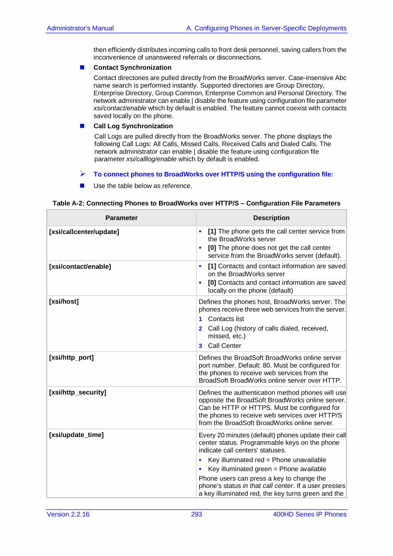
Administrator's Manual A. Configuring Phones in Server-Specific Deployments
Version 2.2.16 293 400HD Series IP Phones
then efficiently distributes incoming calls to front desk personnel, saving callers from the inconvenience of unanswered referrals or disconnections.
Contact Synchronization Contact directories are pulled directly from the BroadWorks server. Case-insensive Abc name search is performed instantly. Supported directories are Group Directory, Enterprise Directory, Group Common, Enterprise Common and Personal Directory. The network administrator can enable | disable the feature using configuration file parameter xsi/contact/enable which by default is enabled. The feature cannot coexist with contacts saved locally on the phone.
Call Log Synchronization Call Logs are pulled directly from the BroadWorks server. The phone displays the following Call Logs: All Calls, Missed Calls, Received Calls and Dialed Calls. The network administrator can enable | disable the feature using configuration file parameter xsi/calllog/enable which by default is enabled.
To connect phones to BroadWorks over HTTP/S using the configuration file: Use the table below as reference.
Table A-2: Connecting Phones to BroadWorks over HTTP/S – Configuration File Parameters
Parameter Description
[xsi/callcenter/update] [1] The phone gets the call center service from the BroadWorks server
[0] The phone does not get the call center service from the BroadWorks server (default).
[xsi/contact/enable] [1] Contacts and contact information are saved on the BroadWorks server
[0] Contacts and contact information are saved locally on the phone (default)
[xsi/host] Defines the phones host, BroadWorks server. The phones receive three web services from the server. 1 Contacts list 2 Call Log (history of calls dialed, received,
missed, etc.) 3 Call Center
[xsi/http_port] Defines the BroadSoft BroadWorks online server port number. Default: 80. Must be configured for the phones to receive web services from the BroadSoft BroadWorks online server over HTTP.
[xsi/http_security] Defines the authentication method phones will use opposite the BroadSoft BroadWorks online server. Can be HTTP or HTTPS. Must be configured for the phones to receive web services over HTTP/S from the BroadSoft BroadWorks online server.
[xsi/update_time] Every 20 minutes (default) phones update their call center status. Programmable keys on the phone indicate call centers' statuses. Key illuminated red = Phone unavailable Key illuminated green = Phone available Phone users can press a key to change the phone's status in that call center. If a user presses a key illuminated red, the key turns green and the
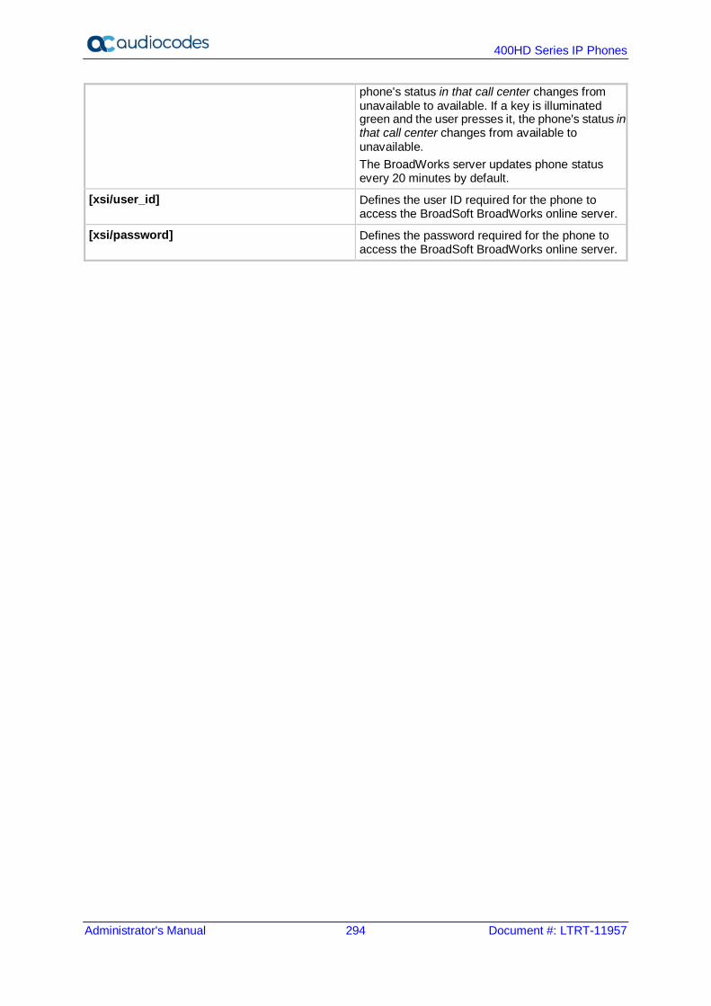
400HD Series IP Phones
Administrator's Manual 294 Document #: LTRT-11957
phone's status in that call center changes from unavailable to available. If a key is illuminated green and the user presses it, the phone's status in that call center changes from available to unavailable. The BroadWorks server updates phone status every 20 minutes by default.
[xsi/user_id] Defines the user ID required for the phone to access the BroadSoft BroadWorks online server.
[xsi/password] Defines the password required for the phone to access the BroadSoft BroadWorks online server.

Administrator's Manual A. Configuring Phones in Server-Specific Deployments
Version 2.2.16 295 400HD Series IP Phones
A.1.7 Configuring Shared Call Appearance The SCA feature enables multiple phones to be associated in an SCA group so that calls can be made or received on any phone in the group.
Note:
• The 440HD phone fully supports the Shared Call Appearance (SCA) feature. • The 405 / 405HD / 420HD / 430HD phones support the feature as participant only.
Figure A-7: Shared Call Appearance with Multiple Call Appearance
To configure Shared Calls Appearance: 1. In the BroadSoft server, assign Shared Call Appearance to the user: Under the 'User'
level, select the Call Control option, and then click the Shared Call Appearance tab.
Figure A-8: BroadSoft Server - Assigning Shared Calls Appearance to a User
Shared line 1 Shared line 2 Shared line 3 Shared line 4
Speed Dials for quick transfer from main line

400HD Series IP Phones
Administrator's Manual 296 Document #: LTRT-11957
2. On the Shared Call Appearance page shown in the figure above, click Add to configure an 'Identity/Device Profile Type', and then use the table below as reference to configure the parameters.
Table A-3: BroadSoft Server - Shared Call Appearance – Identity/Device Profile Type
Parameter Description
Alert all appearances for Click-to-Dial calls See BroadSoft's documentation for detailed information. Select this option when you want your Click-To-Dial calls to ring all phones that have your line appearance. Clear the option if you prefer your line to ring your phone only.
Alert all appearances for Group Paging calls See BroadSoft's documentation for detailed information.
Allow call retrieve from another location See BroadSoft's documentation for detailed information. Select this option when you use a feature access code to automatically retrieve a call that was answered at another Shared Call Appearance of your number.
Multiple Call Arrangement See BroadSoft's documentation for detailed information. Select On to allow multiple calls using your phone number / ID to be dialed or answered simultaneously across all Shared Call Appearances of your number. Select Allow bridging between locations when you want to use a feature access code to bridge a 3-way conference call automatically for any call that has been answered at another Shared Call Appearance of your number. Select Enable Call Park notification for the phone to alert the user visually and audially when a parked call is received.
Bridge Warning tone See BroadSoft's documentation for detailed information. Select the type of Bridge Warning tone treatment you prefer when you bridge and join a call using a feature access code. Select None to apply no tone alert treatment upon your entry to the call. Select Barge-in only to provide a single tone alert. Select Barge-in and repeat every 30 seconds to provide a tone alert at that interval.
3. Click the Edit link adjacent to the selected Line/Port to modify a specific phone that has
a Shared Call Appearance of your line. 4. Click OK.
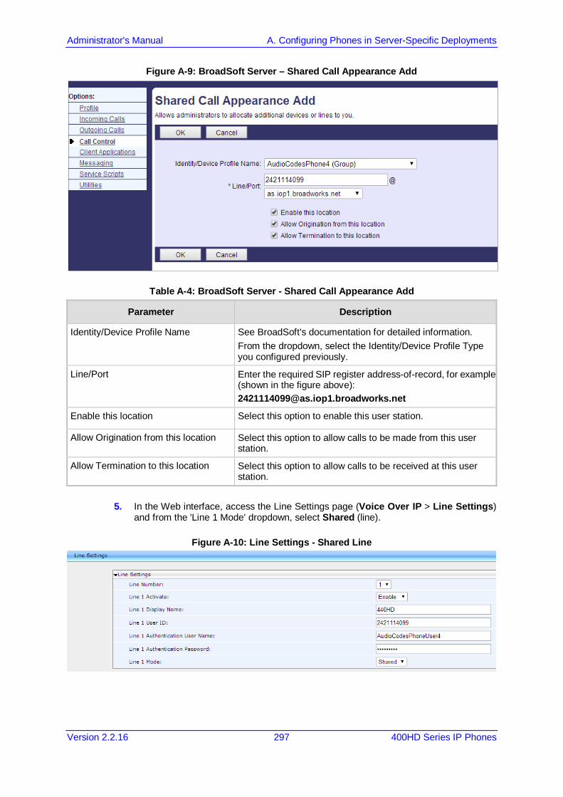
Administrator's Manual A. Configuring Phones in Server-Specific Deployments
Version 2.2.16 297 400HD Series IP Phones
Figure A-9: BroadSoft Server – Shared Call Appearance Add
Table A-4: BroadSoft Server - Shared Call Appearance Add
Parameter Description
Identity/Device Profile Name See BroadSoft's documentation for detailed information. From the dropdown, select the Identity/Device Profile Type you configured previously.
Line/Port Enter the required SIP register address-of-record, for example (shown in the figure above): [email protected]
Enable this location Select this option to enable this user station.
Allow Origination from this location Select this option to allow calls to be made from this user station.
Allow Termination to this location Select this option to allow calls to be received at this user station.
5. In the Web interface, access the Line Settings page (Voice Over IP > Line Settings)
and from the 'Line 1 Mode' dropdown, select Shared (line).
Figure A-10: Line Settings - Shared Line
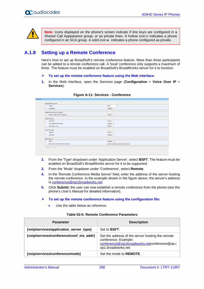
400HD Series IP Phones
Administrator's Manual 298 Document #: LTRT-11957
Note: Icons displayed on the phone's screen indicate if line keys are configured in a Shared Call Appearance group, or as private lines. A hollow icon indicates a phone configured in an SCA group. A solid icon indicates a phone configured as private.
A.1.8 Setting up a Remote Conference Here's how to set up BroadSoft’s remote conference feature. More than three participants can be added to a remote conference call. A 'local' conference only supports a maximum of three. The feature must be enabled on BroadSoft's BroadWorks server for it to function.
To set up the remote conference feature using the Web interface: 1. In the Web interface, open the Services page (Configuration > Voice Over IP >
Services).
Figure A-11: Services - Conference
2. From the 'Type' dropdown under 'Application Server', select BSFT. The feature must be
enabled on BroadSoft's BroadWorks server for it to be supported. 3. From the 'Mode' dropdown under 'Conference', select Remote. 4. In the 'Remote Conference Media Server' field, enter the address of the server hosting
the remote conference. In the example shown in the figure above, the server's address is [email protected]
5. Click Submit; the user can now establish a remote conference from the phone (see the phone's User's Manual for detailed information).
To set up the remote conference feature using the configuration file:
• Use the table below as reference.
Table 53-5: Remote Conference Parameters
Parameter Description
[voip/services/application_server_type] Set to BSFT.
[voip/services/conference/conf_ms_addr] Set the address of the server hosting the remote conference. Example: [email protected]@as.iop1.broadworks.net
[voip/services/conference/mode] Set the mode to REMOTE.

Administrator's Manual A. Configuring Phones in Server-Specific Deployments
Version 2.2.16 299 400HD Series IP Phones
A.1.9 Loading the Corporate Directory to the Phone Here's how to load the Corporate Directory to the phone. The Corporate Directory can be loaded either manually, by loading a (configurable) txt, cfg, or xml file listing all employees and their
details, to the phone, via the Directory page in the Web interface automatically, by placing the (configurable) txt, cfg, or xml file on the BroadSoft
BroadWorks server, and then when the phone is connected to the network, the phone pulls and automatically uploads the file from the server.
To load the Corporate Directory manually, via the the Web interface: 1. In the Web interface, open the Directory page (Configuration > Personal Settings >
Directory).
Figure A-12: Directory
2. In the Corporate Direction section of the screen, click Browse and navigate to and
select the txt, cfg, or xml file on your PC. 3. Click the adjacent Load Corporate Directory button; the file is loaded onto the phone. 4. Verify the upload: On the phone, press the MENU key, navigate down to select the
Directory option, and then select Corporate directory; the directory opens displaying the contacts listed in the corporate directory.
To load the Corporate Directory automatically, via the BroadSoft server: Place the txt, cfg, or xml file file on the BroadSoft BroadWorks server; when the phone is
connected to the network, it pulls and automatically loads the file to the phone.

400HD Series IP Phones
Administrator's Manual 300 Document #: LTRT-11957
A.1.10 Adding a Contact to the Corporate Directory Here's how to add a contact to the Corporate Directory.
To add a contact to the Corporate Directory: In the Directory page shown in the figure above, enter the contact's Name, Office, Home
and Mobile number fields, and then click Submit.
A.1.11 Deleting a Contact from the Corporate Directory Here's how to delete a contact from the Corporate Directory.
To delete a contact to the Corporate Directory: 1. Scroll down in the Directory page (shown in the figure above), and then select the
contact to delete.
Figure A-13: Directory – Delete a Contact
2. Click Delete; the contact is deleted from the Corporate Directory. You can select
multiple contacts and then click Delete All.
A.1.12 Disabling Handset Mode Administrators can disable handset mode using the configuration file parameter 'voip/handset_mode/enabled' whose default is enabled. Some call centers don't want agents to work with any device other than headsets. In this case, their administrators can change the parameter default to disabled.
Note: Some call centers don't even connnect the handsets to the phones. In this case, even though the handsets are not physically connected to the phones, admininstrators should disable the new parameter.
To disable handset mode: Use the table below as reference.
Table A-6: BroadSoft Server - Shared Call Appearance Add
Parameter Description
[voip/handset_mode/enabled] When disabled [0], the handset becomes unavailable. Configure either: [1] = Enabled (default) [0] = Disabled

Administrator's Manual A. Configuring Phones in Server-Specific Deployments
Version 2.2.16 301 400HD Series IP Phones
A.1.13 Displaying a Message in Agents' Phone Screens Call center administrators can use a configuration file parameter to define a message that will be displayed in agents' phone screens, for example: 'Reminder: Your calls might be recorded'. Agents will then see this message, together with the date (in month/day format), displayed in their screens when their phones are in idle state.
To display a message in Agents' phone screens: Use the table below as reference.
Table 53-7: Displaying a Message in Agents' Phone Screens
Parameter Description
[system/display/message_on_screen] Defines a message that will be displayed in agents' phone screens together with the date (in month/day format)
A.1.14 Changing Phone Screen Backlight Timeout Call center administrators can use a configuration file parameter to change phone screens’ backlight timeout. A phone screen's backlight timeout can also be changed on the phone by the user, unless the call center administrator has disabled the possibility with the configuration file parameter personal_settings/menu/backlight_timeout/enabled (see Section 26 for more information about disabling phone hard keys and softkeys).
To change the backlight timeout: Use the table below as reference.
Table 53-8: Backlight Timeout
Parameter Description
[system/lcd/backlight/timeout] Range: 0-6 0 = Always On 1 = 10 seconds (default) 2 = 20 seconds 3 = 30 seconds 4 = 40 seconds 5 = 50 seconds 6 = 60 seconds

400HD Series IP Phones
Administrator's Manual 302 Document #: LTRT-11957
A.2 Asterisk, Coral and Metaswitch
A.2.1 Configuring BLF Configuration of the BLF feature is unique when the selected application server is Asterisk, Coral, or Metaswitch.
Note: This section only applies to the 430HD and 440HD phones.
To configure BLF for Asterisk application server: 1. Open the Services page (Configuration tab > Voice Over IP menu > Services).
Figure A-14: BLF Configuration for Application Server Type - Asterisk
2. From the 'Application Server Type' drop-down list, select either:
• Asterisk • Coral -or- • Metaswitch
3. In the BLF Support group, configure the following: • From the 'Activate' drop-down list (voip/services/busy_lamp_field/enabled
parameter), select Enable. • (Optional) In the 'BLF Subscription Period' field
(voip/services/busy_lamp_field/subscription_period parameter), enter the interval between BLF and SIP SUBSCRIBE messages.
Note: The application server's address is the same as the SIP Registrar address defined by parameter voip/signalling/sip/sip_registrar/addr (see Section 16.2).
4. Click Submit. 5. Define speed dial keys with the BLF feature (see Section 25).
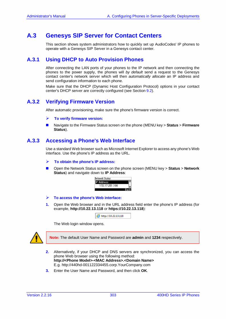
Administrator's Manual A. Configuring Phones in Server-Specific Deployments
Version 2.2.16 303 400HD Series IP Phones
A.3 Genesys SIP Server for Contact Centers This section shows system administrators how to quickly set up AudioCodes' IP phones to operate with a Genesys SIP Server in a Genesys contact center.
A.3.1 Using DHCP to Auto Provision Phones After connecting the LAN ports of your phones to the IP network and then connecting the phones to the power supply, the phones will by default send a request to the Genesys contact center's network server which will then automatically allocate an IP address and send configuration information to each phone. Make sure that the DHCP (Dynamic Host Configuration Protocol) options in your contact center's DHCP server are correctly configured (see Section 9.2).
A.3.2 Verifying Firmware Version After automatic provisioning, make sure the phone's firmware version is correct.
To verify firmware version: Navigate to the Firmware Status screen on the phone (MENU key > Status > Firmware
Status).
A.3.3 Accessing a Phone's Web Interface Use a standard Web browser such as Microsoft Internet Explorer to access any phone's Web interface. Use the phone's IP address as the URL.
To obtain the phone's IP address: Open the Network Status screen on the phone screen (MENU key > Status > Network
Status) and navigate down to IP Address:
To access the phone's Web interface: 1. Open the Web browser and in the URL address field enter the phone's IP address (for
example, http://10.22.13.118 or https://10.22.13.118):
The Web login window opens.
Note: The default User Name and Password are admin and 1234 respectively.
2. Alternatively, if your DHCP and DNS servers are synchronized, you can access the
phone Web browser using the following method: http://<Phone Model>-<MAC Address>.<Domain Name> E.g. http://440hd-001122334455.corp.YourCompany.com
3. Enter the User Name and Password, and then click OK.

400HD Series IP Phones
Administrator's Manual 304 Document #: LTRT-11957
A.3.4 Configuring Dual Registration to Ensure SIP Business Continuity for Agents Here's how to configure dual registration for Genesys SIP Business Continuity, using the Web interface or configuration file. AudioCodes' 420HD phone supports dual registration for integrating into Genesys' SIP Business Continuity architecture. SIP Business Continuity provides the ability for a group of agents to continue offering critical business functions to customers in the event of a loss of all Genesys components running at a particular site. The SIP Business Continuity architecture uses a synchronized, two-site deployment, where Genesys switch and server components are mirrored at each site in an active-active configuration, so that any agent can log in to either switch, at any time. In a standalone SIP Server configuration with Business Continuity mode activated, AudioCodes 420HD phone will register on two sites simultaneously (i.e., register on both peer SIP Servers at the same time).
To configure using the Web Interface: 1. In the Web interface, access the SIP Proxy and Registrar section in the Signaling
Protocol screen (Configuration menu > Voice Over IP > Signaling Protocol):
Figure A-15: Signaling Protocol – SIP Proxy and Registrar
Note: If you choose to use the BroadSoft-based Automatic Call Distributor (ACD) method in a SIP Business Continuity deployment, the 'voip/signalling/sip/redundant_proxy/mode' cfg file parameter and the 'Redundant Proxy Mode' Web interface parameter cannot be set to Simultaneous.

Administrator's Manual A. Configuring Phones in Server-Specific Deployments
Version 2.2.16 305 400HD Series IP Phones
Figure A-16: Signaling Protocol – SIP Proxy and Registrar – Secondary Proxy
2. Configure the parameters using table below as reference.
To configure using configuration file: Use the table below as reference.
Table A-9: SIP Proxy and Registrar Parameters
Parameter Description
Use SIP Proxy [voip/signalling/sip/use_proxy]
Determines whether to use a SIP Proxy server. Configure [1] Enable. [0] Disable (default) [1] Enable
Proxy IP Address or Host Name [voip/signalling/sip/proxy_address]
Enter the IP address or host name (for example, audiocodes.com) of the SIP proxy server. Default: 0.0.0.0
Proxy Port [voip/signalling/sip/proxy_port]
The UDP or TCP port of the SIP proxy server. Range: 1024 to 65535. Default: 5060.
Enable Registrar Keep Alive [voip/signalling/sip/registrar_ka/enabled]
Determines whether to use the registration keep-alive mechanism based on SIP OPTION messages. [0] Disable (default) [1] Enable Note: If there is no response from the server, the
timeout for re-registering is automatically reduced to a user-defined value (voip/signalling/sip/registration_failed_timeout)
When the phone re-registers, the keep-alive messages are re-sent periodically.
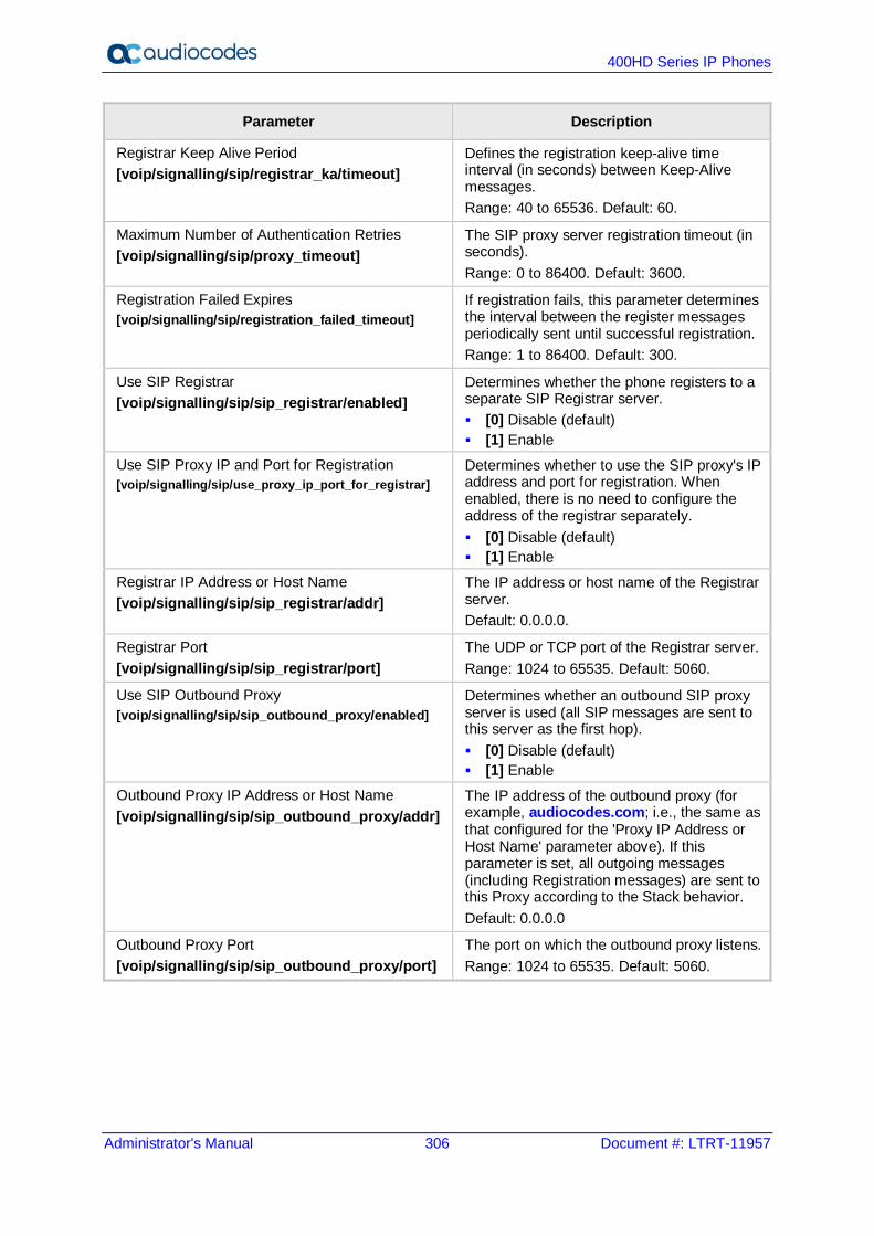
400HD Series IP Phones
Administrator's Manual 306 Document #: LTRT-11957
Parameter Description
Registrar Keep Alive Period [voip/signalling/sip/registrar_ka/timeout]
Defines the registration keep-alive time interval (in seconds) between Keep-Alive messages. Range: 40 to 65536. Default: 60.
Maximum Number of Authentication Retries [voip/signalling/sip/proxy_timeout]
The SIP proxy server registration timeout (in seconds). Range: 0 to 86400. Default: 3600.
Registration Failed Expires [voip/signalling/sip/registration_failed_timeout]
If registration fails, this parameter determines the interval between the register messages periodically sent until successful registration. Range: 1 to 86400. Default: 300.
Use SIP Registrar [voip/signalling/sip/sip_registrar/enabled]
Determines whether the phone registers to a separate SIP Registrar server. [0] Disable (default) [1] Enable
Use SIP Proxy IP and Port for Registration [voip/signalling/sip/use_proxy_ip_port_for_registrar]
Determines whether to use the SIP proxy's IP address and port for registration. When enabled, there is no need to configure the address of the registrar separately. [0] Disable (default) [1] Enable
Registrar IP Address or Host Name [voip/signalling/sip/sip_registrar/addr]
The IP address or host name of the Registrar server. Default: 0.0.0.0.
Registrar Port [voip/signalling/sip/sip_registrar/port]
The UDP or TCP port of the Registrar server. Range: 1024 to 65535. Default: 5060.
Use SIP Outbound Proxy [voip/signalling/sip/sip_outbound_proxy/enabled]
Determines whether an outbound SIP proxy server is used (all SIP messages are sent to this server as the first hop). [0] Disable (default) [1] Enable
Outbound Proxy IP Address or Host Name [voip/signalling/sip/sip_outbound_proxy/addr]
The IP address of the outbound proxy (for example, audiocodes.com; i.e., the same as that configured for the 'Proxy IP Address or Host Name' parameter above). If this parameter is set, all outgoing messages (including Registration messages) are sent to this Proxy according to the Stack behavior. Default: 0.0.0.0
Outbound Proxy Port [voip/signalling/sip/sip_outbound_proxy/port]
The port on which the outbound proxy listens. Range: 1024 to 65535. Default: 5060.

Administrator's Manual A. Configuring Phones in Server-Specific Deployments
Version 2.2.16 307 400HD Series IP Phones
Parameter Description
Redundant Proxy Mode [voip/signalling/sip/redundant_proxy/mode]
The call center's network administrator can select either Disable -OR- Primary Fallback -OR- Simultaneous For the dual-registration feature, select Simultaneous; two proxies are registered simultaneously so that at least one should be up and running at any time, preventing the call center from going down. Note that when using the BroadSoft ACD in a SIP Business Continuity deployment, this parameter cannot be set to Simultaneous.
Secondary Proxy Address [voip/signalling/sip/secondary_proxy/address]
Displayed only when Simultaneous is selected for 'Redundant Proxy Mode' (see previous parameter). Define the IP address of the secondary proxy that will be up simultaneously with the primary.
Secondary Proxy Port [voip/signalling/sip/secondary_proxy/port]
Displayed only when Simultaneous is selected for 'Redundant Proxy Mode' (see the parameter before the previous). Define the port of the secondary proxy that will be up simultaneously with the primary.
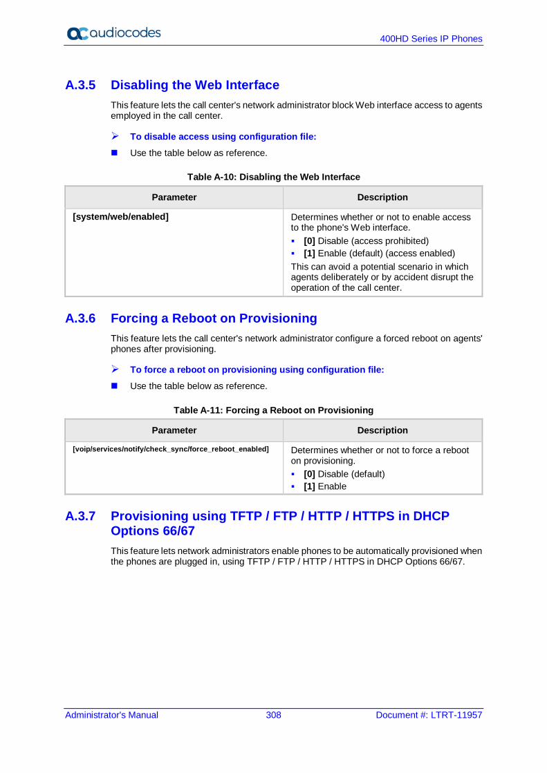
400HD Series IP Phones
Administrator's Manual 308 Document #: LTRT-11957
A.3.5 Disabling the Web Interface This feature lets the call center's network administrator block Web interface access to agents employed in the call center.
To disable access using configuration file: Use the table below as reference.
Table A-10: Disabling the Web Interface
Parameter Description
[system/web/enabled] Determines whether or not to enable access to the phone's Web interface. [0] Disable (access prohibited) [1] Enable (default) (access enabled) This can avoid a potential scenario in which agents deliberately or by accident disrupt the operation of the call center.
A.3.6 Forcing a Reboot on Provisioning This feature lets the call center's network administrator configure a forced reboot on agents' phones after provisioning.
To force a reboot on provisioning using configuration file: Use the table below as reference.
Table A-11: Forcing a Reboot on Provisioning
Parameter Description
[voip/services/notify/check_sync/force_reboot_enabled] Determines whether or not to force a reboot on provisioning. [0] Disable (default) [1] Enable
A.3.7 Provisioning using TFTP / FTP / HTTP / HTTPS in DHCP Options 66/67 This feature lets network administrators enable phones to be automatically provisioned when the phones are plugged in, using TFTP / FTP / HTTP / HTTPS in DHCP Options 66/67.

Administrator's Manual A. Configuring Phones in Server-Specific Deployments
Version 2.2.16 309 400HD Series IP Phones
A.3.8 Enabling Agents to Sign in with Phone Numbers This feature lets the call center administrator power up all phones without setting a valid SIP account. When an agent then wants to use their phone, they register to the network with their phone number.
To enable the feature using configuration file: Use the table below as reference.
Table A-12: Enabling Agents to Sign in with Phone Numbers
Parameter Description
[system/login_sk_before_signed_in] Determines whether or not to enable agents sign in with phone numbers. [0] Disable (default) [1] Enable
A.3.9 Locking Agents' Phones' Alphabetical Keys
Note: Only applies to the 420HD and 405/405HD models.
This feature lets call center network administrators lock agents' phones' alphabetical (non-numerical) keys so that only numerical keys are available to them. This feature provides call centers the option to limit agents to work-specific tasks. The feature reduces private activity on the part of agents. Agents cannot, for example, add contacts to a personal directory. When this feature is enabled, agents can only use numbers. Only two menus are available in agents' phone screens: Status Administration
To lock alphabetical keys using configuration file: Use the table below as reference.
Table A-13: Locking Agents Phones Alphabetical Keys
Parameter Description
[voip/block_non_numeric_key] Determines whether or not to lock Agents' phones' alphabetical keys and only allow Agents to use numerical keys. [0] Disable (default) [1] Enable
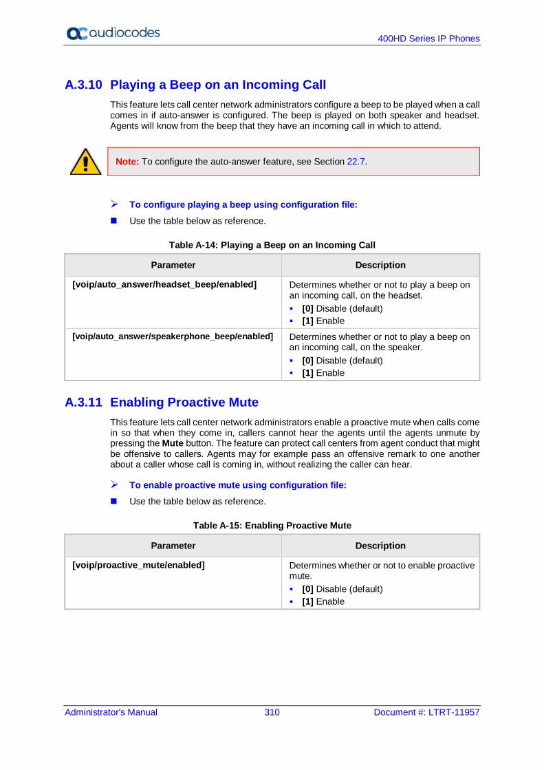
400HD Series IP Phones
Administrator's Manual 310 Document #: LTRT-11957
A.3.10 Playing a Beep on an Incoming Call This feature lets call center network administrators configure a beep to be played when a call comes in if auto-answer is configured. The beep is played on both speaker and headset. Agents will know from the beep that they have an incoming call in which to attend.
Note: To configure the auto-answer feature, see Section 22.7.
To configure playing a beep using configuration file: Use the table below as reference.
Table A-14: Playing a Beep on an Incoming Call
Parameter Description
[voip/auto_answer/headset_beep/enabled] Determines whether or not to play a beep on an incoming call, on the headset. [0] Disable (default) [1] Enable
[voip/auto_answer/speakerphone_beep/enabled] Determines whether or not to play a beep on an incoming call, on the speaker. [0] Disable (default) [1] Enable
A.3.11 Enabling Proactive Mute This feature lets call center network administrators enable a proactive mute when calls come in so that when they come in, callers cannot hear the agents until the agents unmute by pressing the Mute button. The feature can protect call centers from agent conduct that might be offensive to callers. Agents may for example pass an offensive remark to one another about a caller whose call is coming in, without realizing the caller can hear.
To enable proactive mute using configuration file: Use the table below as reference.
Table A-15: Enabling Proactive Mute
Parameter Description
[voip/proactive_mute/enabled] Determines whether or not to enable proactive mute. [0] Disable (default) [1] Enable
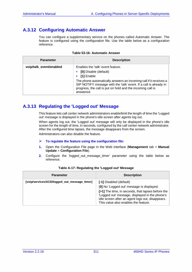
Administrator's Manual A. Configuring Phones in Server-Specific Deployments
Version 2.2.16 311 400HD Series IP Phones
A.3.12 Configuring Automatic Answer You can configure a supplementary service on the phones called Automatic Answer. The feature is configured using the configuration file. Use the table below as a configuration reference.
Table 53-16: Automatic Answer
Parameter Description
voip/talk_event/enabled Enables the 'talk' event feature. [0] Disable (default) [1] Enable The phone automatically answers an incoming call if it receives a SIP NOTIFY message with the 'talk' event. If a call is already in progress, the call is put on hold and the incoming call is answered.
A.3.13 Regulating the 'Logged out' Message This feature lets call center network administrators enable/limit the length of time the 'Logged out' message is displayed in the phone's idle screen after agents log out. When agents log out, the 'Logged out' message will only be displayed in the phone's idle screen for the length of time, in seconds, configured by the call center network administrator. After the configured time lapses, the message disappears from the screen. Administrators can also disable the feature.
To regulate the feature using the configuration file: 1. Open the Configuration File page in the Web interface (Management tab > Manual
Update > Configuration File). 2. Configure the 'logged_out_message_timer' parameter using the table below as
reference.
Table A-17: Regulating the 'Logged out' Message
Parameter Description
[voip/services/ACD/logged_out_message_timer] [-1] Disabled (default) [0] No 'Logged out' message is displayed. [>1] The time, in seconds, that lapses before the 'Logged out' message, displayed in the phone's idle screen after an agent logs out, disappears. This value also enables the feature.

400HD Series IP Phones
Administrator's Manual 312 Document #: LTRT-11957
A.3.14 3PCC (Third Party Call Control) The 3PCC feature lets an agent control their phone remotely from a computer application. 3PCC always supports the following functions: MakeCall (call initiation/setup) Release Hold Retrieve Transfer Consult Conference DTMF
To configure 3PCC using configuration file: Use the table below as reference.
Table A-18: 3PCC Parameters
Parameter Description
[voip/talk_event/enabled] [0] Disable (default) [1] Enable
Note: voip/talk_event must be enabled for 3PCC to function.
A.3.14.1 Enabling 3PCC Calls This feature complies with the RFC 3725 standard for 3PCC in SIP for 'Black Holed' and 'Non SDP'. See the RFC for detailed information.
To enable 3PCC calls using the configuration file: 1. Open the Configuration File page in the Web interface (Management tab > Manual
Update > Configuration File). 2. Configure the capability using the table below as reference.
Table A-19: Enabling 3PCC Calls
Parameter Description
[3PCC/make_call/enabled] [0] = Disable [1] = Enable (default)

Administrator's Manual A. Configuring Phones in Server-Specific Deployments
Version 2.2.16 313 400HD Series IP Phones
A.3.15 Disabling Handset Mode Administrators can disable handset mode using the configuration file parameter 'voip/handset_mode/enabled' whose default is enabled. Some call centers don't want agents to work with any device other than headsets. In this case, their administrators can change the parameter default to disabled.
Note: Some call centers don't even connnect the handsets to the phones. In this case, even though the handsets are not physically connected to the phones, admininstrators should disable the new parameter.
To disable handset mode: Use the table below as reference.
Table A-20: BroadSoft Server - Shared Call Appearance Add
Parameter Description
[voip/handset_mode/enabled] When disabled [0], the handset becomes unavailable. Configure either: [1] = Enabled (default) [0] = Disabled
A.3.16 Changing Phone Screen Backlight Timeout Call center administrators can use a configuration file parameter to change phone screens’ backlight timeout. A phone screen's backlight timeout can also be changed on the phone by the user, unless the call center administrator has disabled the possibility with the configuration file parameter personal_settings/menu/backlight_timeout/enabled (see Section 26 for more information about disabling phone hard keys and softkeys).
To change the backlight timeout: Use the table below as reference.
Table 53-21: Backlight Timeout
Parameter Description
[system/lcd/backlight/timeout] Range: 0-6 0 = Always On 1 = 10 seconds (default) 2 = 20 seconds 3 = 30 seconds 4 = 40 seconds 5 = 50 seconds 6 = 60 seconds
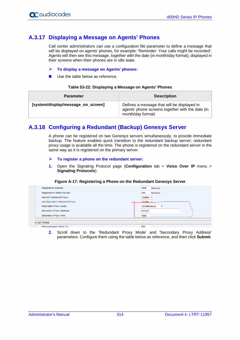
400HD Series IP Phones
Administrator's Manual 314 Document #: LTRT-11957
A.3.17 Displaying a Message on Agents' Phones Call center administrators can use a configuration file parameter to define a message that will be displayed on agents' phones, for example: 'Reminder: Your calls might be recorded'. Agents will then see this message, together with the date (in month/day format), displayed in their screens when their phones are in idle state.
To display a message on Agents' phones: Use the table below as reference.
Table 53-22: Displaying a Message on Agents' Phones
Parameter Description
[system/display/message_on_screen] Defines a message that will be displayed in agents' phone screens together with the date (in month/day format)
A.3.18 Configuring a Redundant (Backup) Genesys Server A phone can be registered on two Genesys servers simultaneously, to provide immediate backup. The feature enables quick transition to the redundant backup server; redundant proxy usage is available all the time. The phone is registered on the redundant server in the same way as it is registered on the primary server.
To register a phone on the redundant server: 1. Open the Signaling Protocol page (Configuration tab > Voice Over IP menu >
Signaling Protocols).
Figure A-17: Registering a Phone on the Redundant Genesys Server
2. Scroll down to the ‘Redundant Proxy Mode’ and 'Secondary Proxy Address'
parameters. Configure them using the table below as reference, and then click Submit.

Administrator's Manual A. Configuring Phones in Server-Specific Deployments
Version 2.2.16 315 400HD Series IP Phones
Table 53-23: Redundant Genesys Server - Parameters
Parameter Description
Redundant Proxy Mode From the dropdown, select Simultaneously; you're now in Dual Registration mode; when in this mode, the value of the parameter 'Retransmission Timer T1' is taken from the configuration file parameter 'voip/signalling/sip/redundant_proxy/dual_reg/t1' rather than from the 'Retransmission Timer T1' parameter (see Table 16-7 for more information about this parameter).
Secondary Proxy Address
Provide the IP address of the redundant proxy; the phone then registers on both servers from the outset, instead of transitioning from one to another.
A.3.18.1 Configuring Retransmission Timer T1 Using the Configuration File Configuration of the T1 retransmission timer is only relevant when in dual registration mode, i.e., after configuring a redundant Genesys server, as shown in the previous section.
Configuring Retransmission Timer T1 using the configuration file: 3. Open the Configuration File page in the Web interface (Management tab > Manual
Update > Configuration File). 4. Configure the capability using the table below as reference.
Table A-24: Retransmission Timer T1 - Parameter
Parameter Description
[voip/signalling/sip/redundant_proxy/dual_reg/t1]
Only relevant if dual registration / redundancy server is configured. Allows quicker retransmission of SIP messages than the Web interface parameter 'Transmission Timer T1' and overrides it if configured (see Table 16-7 for more information). Default: 20 milliseconds. Range: 20-200.

400HD Series IP Phones
Administrator's Manual 316 Document #: LTRT-11957
This page is intentionally left blank.
Administrator's Manual B. Configuring Automatic Call Distribution (ACD)
Version 2.2.16 317 400HD Series IP Phones
B Configuring Automatic Call Distribution (ACD)
Note:
• AudioCodes' IP Phones seamlessly interwork with Genesys SIP Server to support ACD functionality. The phones support two different ACD methods: a legacy method referred to as 'Genesys' in the Web interface, and an enhanced method based on BroadSoft’s ACD capabilities, referred to as 'BROADSOFT' in the Web interface.
• For optimal ACD functionality with Genesys SIP Server, the BroadSoft-based ACD method must be chosen.
This appendix shows how to enable the ACD (Automatic Call Distribution) feature on the phone using either the Web interface or the configuration file. The feature automatically distributes incoming calls to agents' phones on the basis of agent availability and unavailability. In contact centers, ACD is a key feature of CTI (Computer Telephony Integration). The feature automatically distributes incoming calls to a specific group of terminals that contact center agents use. Most ACD functionality is the SIP server's responsibility; however, users must inform the Call Center SIP server on the following events: Whenever the call center representitive logs in or out on the phone. This information is
included in a SIP SUBSCRIBE message. Whenever the call center representitive indicates whether they are ready or not to take a
call. When the BroadSoft server is configured, the user can also specify the reason for their unavailability e.g. Lunch break. All this information is included in a SIP NOTIFY message.
Whenever the user is busy with After Call Work (ACW) (only relevant when a BroadSoft SIP server is configured). This information is included in a SIP NOTIFY message.
All the above actions can be performed on the phone (see the phone's User's Manual). The Call Center SIP server then uses the above presence information to automatically distribute calls between agents based on their availability. ACD systems allow companies that handle a large number of incoming phone calls to direct the callers to a company employee who is able to talk at the earliest opportunity. The feature is typically implemented in contact centers encountering large numbers of incoming customer calls that must be distributed to available agents to provide immediate support to callers. The feature automatically directs incoming calls to agents working in the contact center whose presence status is 'Ready' rather than not ready. The feature's main benefit is to reduce the time customers are kept waiting and thereby improve service. AudioCodes' IP phones seamlessly interwork with Genesys' SIP server to support the ACD feature. Once an agent signs in on their phone to ACD, their status is set to 'Ready' and synchronized with Genesys' Server. Incoming calls are directed to an agent whenever their status becomes 'Ready'.
Note:
• This feature applies to the 405/405HD, 420HD, 430HD and 440HD phone models. • The Web interface screenshots shown in this section are of the 420HD model.
They're identical to those of the 405/405HD, 430HD and 440HD phone models.

400HD Series IP Phones
Administrator's Manual 318 Document #: LTRT-11957
To configure the ACD server using the Web interface: 1. In the Web interface, access the ACD page (Configuration tab > Advanced
Applications > ACD):
Figure B-1: ACD
Note: For optimal ACD functionality with Genesys, select the BROADSOFT option from the 'Server Type' dropdown.
Figure B-2: ACD – Unavailable Reason Code
2. Configure the parameters using the table below as reference.

Administrator's Manual B. Configuring Automatic Call Distribution (ACD)
Version 2.2.16 319 400HD Series IP Phones
To configure the ACD server using the configuration file: Define a path and configure the parameters using the table below as reference.
Table B-1: ACD Parameters
Parameter Description
Active [voip/services/ACD/enabled]
From the 'Active' drop-down, choose Enable. [0] Disable (default) [1] Enable
Server Type [voip/services/ACD/server_type]
From the 'Server Type' drop-down list, select GENESYS or BROADSOFT. Select the BROADSOFT option for optimal ACD functionality with Genesys. When you select BROADSOFT, after logging into the ACD server, the ACW (After Call Work) softkey will be displayed on the phone and the Missed softkey displayed in the command menu along with the FORWARD and DND options. Note that administrators can optionally hide the ACW softkey (see the next parameter).
[voip/services/ACD/show_acw_softkey/enabled] Allows administrators to hide the ACW softkey. After logging into the call center's Automatic Call Distributor (ACD) server, the ACW softkey is by default displayed on the phone [1]. Administrators can change this default and hide the softkey [0]. [0] Disable [1] Enable (default) The default softkey layout is ACW, READY/Not Ready (when the user is logged on), Login/Logout and Command menu items including Missed and DND. When the ACW softkey is disabled, the display stays the same but without the ACW softkey.
[system/dnd/show_softkey] Removes the DND item from the Call Menu where it's displayed by default when ACD is enabled. [0] Removes DND from the Call Menu [1] Displays DND in the Call Menu (default)
[system/forward/show_softkey] Removes the Forward item from the Call Menu where it's displayed by default when ACD is enabled. [0] Removes Forward from the Call Menu [1] Displays Forward in the Call Menu (default)
Use Sip Server As ACD Server [voip/services/ACD/server_use_sip_server]
From the drop-down, choose Enable. [0] Disable [1] Enable
Expire Time [voip/services/ACD/expire_time]
The server registration timeout, in seconds. Range: 0 to 86400. Default: 3600.
Server Address [voip/services/ACD/server_address]
Displayed only when 'Use SIP Server As ACD Server' is set to Disable (see previous). Defines the IP address of the ACD server. Default: 0.0.0.0
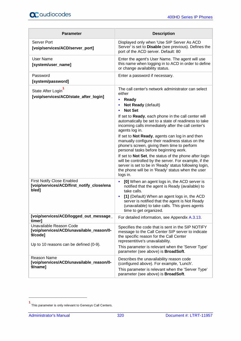
400HD Series IP Phones
Administrator's Manual 320 Document #: LTRT-11957
Parameter Description
Server Port [voip/services/ACD/server_port]
Displayed only when 'Use SIP Server As ACD Server' is set to Disable (see previous). Defines the port of the ACD server. Default: 80
User Name [system/user_name]
Enter the agent's User Name. The agent will use this name when logging in to ACD in order to define or change availability status.
Password [system/password]
Enter a password if necessary.
State After Login1
[voip/services/ACD/state_after_login]
The call center's network administrator can select either Ready Not Ready (default) Not Set If set to Ready, each phone in the call center will automatically be set to a state of readiness to take incoming calls immediately after the call center's agents log in. If set to Not Ready, agents can log in and then manually configure their readiness status on the phone's screen, giving them time to perform personal tasks before beginning work. If set to Not Set, the status of the phone after login will be controlled by the server. For example, if the server is set to be in 'Ready' status following login, the phone will be in 'Ready' status when the user logs in.
First Notify Close Enabled [voip/services/ACD/first_notify_close/enabled]
[0] When an agent logs in, the ACD server is notified that the agent is Ready (available) to take calls.
[1] (Default) When an agent logs in, the ACD server is notified that the agent is Not Ready (unavailable) to take calls. This gives agents time to get organized.
[voip/services/ACD/logged_out_message_timer]
For detailed information, see Appendix A.3.13.
Unavailable Reason Code [voip/services/ACD/unavailable_reason/0-9/code] Up to 10 reasons can be defined (0-9).
Specifies the code that is sent in the SIP NOTIFY message to the Call Center SIP server to indicate the specific reason for the Call Center representitive's unavailability. This parameter is relevant when the 'Server Type' parameter (see above) is BroadSoft.
Reason Name [voip/services/ACD/unavailable_reason/0-9/name]
Describes the unavailability reason code (configured above). For example, 'Lunch'. This parameter is relevant when the 'Server Type' parameter (see above) is BroadSoft.
1 This parameter is only relevant to Genesys Call Centers.

Administrator's Manual B. Configuring Automatic Call Distribution (ACD)
Version 2.2.16 321 400HD Series IP Phones
B.1 Softkey Display and Command Menu Options The following tables show the different softkey display states and command menu options that are available according to the user's login state and the configured SIP server.
Table B-2: BroadSoft-Softkey Display States and Command Menu Options
State Softkey #0 Softkey #1 Softkey #2 Softkey #3
Idle ACD Disabled
Directory Missed Forward DnD
ACD Enabled (logged out)
Missed - Login Command Menu: Forward DnD
ACD Enabled (logged in)
ACW Not Ready or Ready Logout Command Menu: Missed Forward DnD
Ongoing Call State
ACD Disabled
Hold Conf New Call End
ACD Enabled (logged out)
ACD Enabled (logged in)
State Softkey #0 Softkey #1 Softkey #2 Softkey #3
Idle ACD Disabled
Directory Missed Forward DnD
ACD Enabled (logged out)
Missed - Login Command Menu: Forward DnD
ACD Enabled (logged in)
Missed Not Ready or Ready Logout Command Menu: Forward DnD
Ongoing Call State
ACD Disabled
Hold Conf New Call End
ACD Enabled (logged out)
ACD Enabled (logged in

400HD Series IP Phones
Administrator's Manual 322 Document #: LTRT-11957
This page is intentionally left blank.
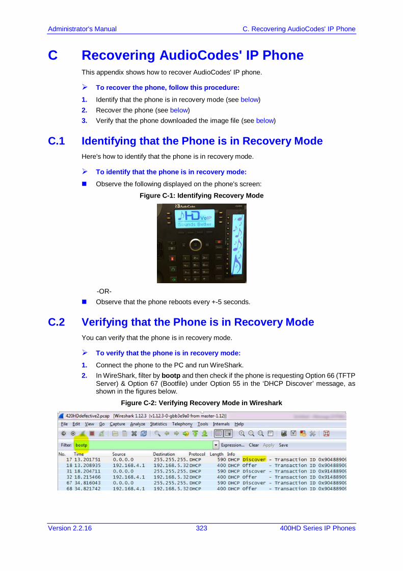
Administrator's Manual C. Recovering AudioCodes' IP Phone
Version 2.2.16 323 400HD Series IP Phones
C Recovering AudioCodes' IP Phone This appendix shows how to recover AudioCodes' IP phone.
To recover the phone, follow this procedure: 1. Identify that the phone is in recovery mode (see below) 2. Recover the phone (see below) 3. Verify that the phone downloaded the image file (see below)
C.1 Identifying that the Phone is in Recovery Mode Here's how to identify that the phone is in recovery mode.
To identify that the phone is in recovery mode: Observe the following displayed on the phone's screen:
Figure C-1: Identifying Recovery Mode
-OR-
Observe that the phone reboots every +-5 seconds.
C.2 Verifying that the Phone is in Recovery Mode You can verify that the phone is in recovery mode.
To verify that the phone is in recovery mode: 1. Connect the phone to the PC and run WireShark. 2. In WireShark, filter by bootp and then check if the phone is requesting Option 66 (TFTP
Server) & Option 67 (Bootfile) under Option 55 in the ‘DHCP Discover’ message, as shown in the figures below.
Figure C-2: Verifying Recovery Mode in Wireshark
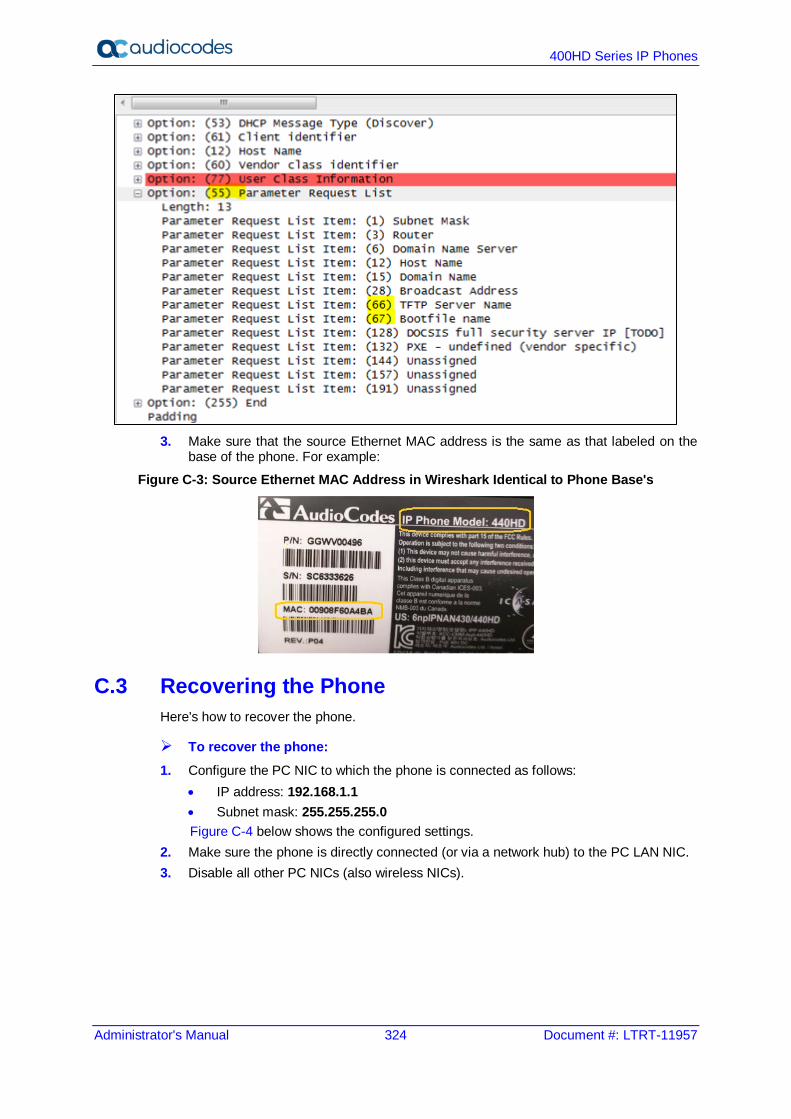
400HD Series IP Phones
Administrator's Manual 324 Document #: LTRT-11957
3. Make sure that the source Ethernet MAC address is the same as that labeled on the
base of the phone. For example:
Figure C-3: Source Ethernet MAC Address in Wireshark Identical to Phone Base's
C.3 Recovering the Phone Here's how to recover the phone.
To recover the phone: 1. Configure the PC NIC to which the phone is connected as follows:
• IP address: 192.168.1.1 • Subnet mask: 255.255.255.0 Figure C-4 below shows the configured settings.
2. Make sure the phone is directly connected (or via a network hub) to the PC LAN NIC. 3. Disable all other PC NICs (also wireless NICs).
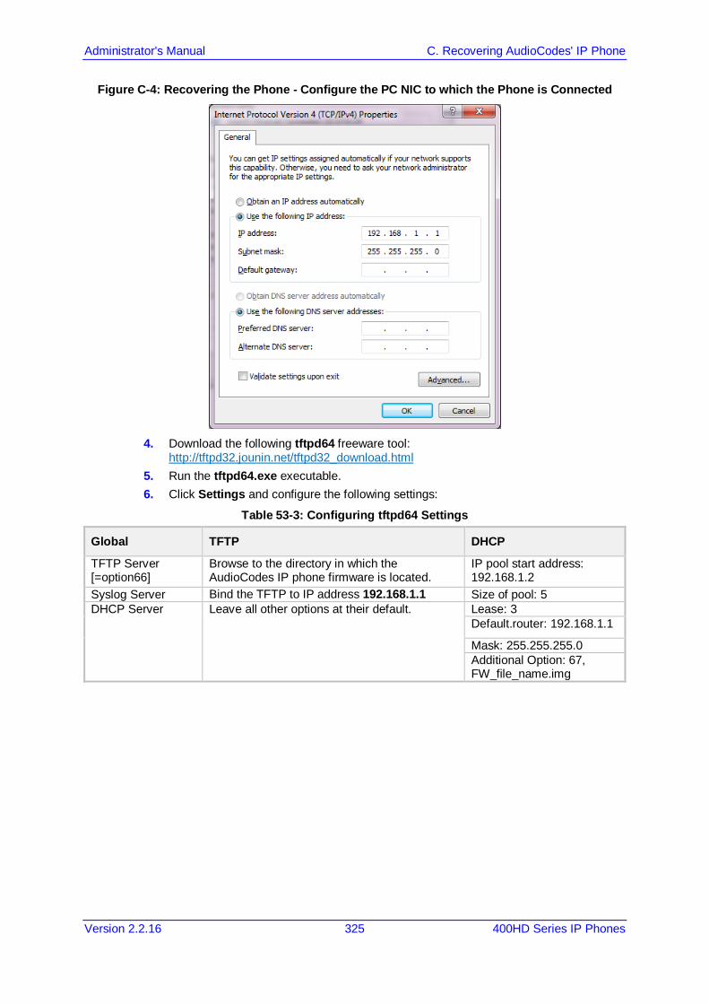
Administrator's Manual C. Recovering AudioCodes' IP Phone
Version 2.2.16 325 400HD Series IP Phones
Figure C-4: Recovering the Phone - Configure the PC NIC to which the Phone is Connected
4. Download the following tftpd64 freeware tool:
http://tftpd32.jounin.net/tftpd32_download.html 5. Run the tftpd64.exe executable. 6. Click Settings and configure the following settings:
Table 53-3: Configuring tftpd64 Settings
Global TFTP DHCP
TFTP Server [=option66]
Browse to the directory in which the AudioCodes IP phone firmware is located.
IP pool start address: 192.168.1.2
Syslog Server Bind the TFTP to IP address 192.168.1.1 Size of pool: 5 DHCP Server Leave all other options at their default. Lease: 3
Default.router: 192.168.1.1
Mask: 255.255.255.0 Additional Option: 67, FW_file_name.img

400HD Series IP Phones
Administrator's Manual 326 Document #: LTRT-11957
7. For tftps64 to accept the new settings, close and open tftpd64.
After (1) tftpd64 is restarted, (2) the phone is directly connected to the PC, and (3) the network settings referred to above are applied, the phone immediately gets the required options [66 and 67] and begins downloading the firmware. Verify that the phone is downloading the image file as shown in the next section.

Administrator's Manual C. Recovering AudioCodes' IP Phone
Version 2.2.16 327 400HD Series IP Phones
C.4 Verifying that the Phone is Downloading the Image File Here's how to verify that the phone is downloading the firmware image file.
To verify that the phone is downloading the image file: use Wireshark -or- use tftpd64 -or- use the phone screen
C.4.1 Verifying Using Wireshark 1. In Wireshark, verify that the four DHCP ‘DORA’ (Discover; Offer; Request; ACK) steps
are accomplished, as shown in the figure below.
Figure C-5: Verifying with Wireshark that the Phone is Downloading Phone .img File
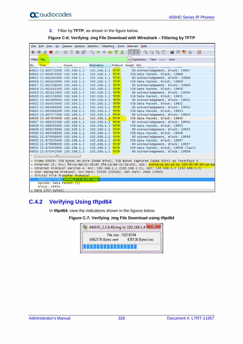
400HD Series IP Phones
Administrator's Manual 328 Document #: LTRT-11957
2. Filter by TFTP, as shown in the figure below.
Figure C-6: Verifying .img File Download with Wireshark – Filtering by TFTP
C.4.2 Verifying Using tftpd64 In tftpd64, view the indications shown in the figures below.
Figure C-7: Verifying .img File Download using tftpd64

Administrator's Manual C. Recovering AudioCodes' IP Phone
Version 2.2.16 329 400HD Series IP Phones
Figure C-8: Verifying .img File Download using tftpd64
C.4.3 Verifying on the Phone In tftpd64, view the indications shown in the figures below.
Figure C-9: Verifying .img File Download on the Phone
Important: Do not unplug / power-off the phone while the screen displays the message shown below.
You can disconnect the phone from the PC and connect to the network LAN only after the firmware upgrade finishes, that is, after the phone's screen displays the following: Discovering CDP…Discovering LLDP…Acquiring IP… The phone is now up, functioning, and ready to be provisioned.

400HD Series IP Phones
Administrator's Manual 330 Document #: LTRT-11957
This page is intentionally left blank.
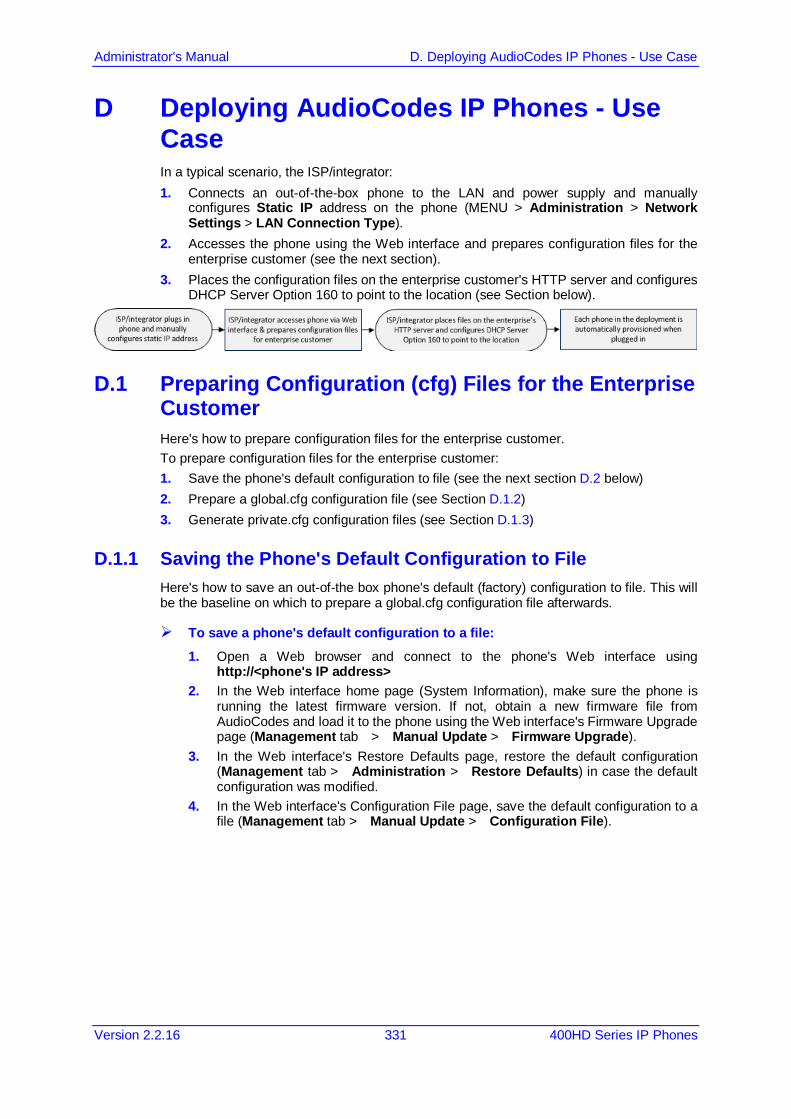
Administrator's Manual D. Deploying AudioCodes IP Phones - Use Case
Version 2.2.16 331 400HD Series IP Phones
D Deploying AudioCodes IP Phones - Use Case In a typical scenario, the ISP/integrator: 1. Connects an out-of-the-box phone to the LAN and power supply and manually
configures Static IP address on the phone (MENU > Administration > Network Settings > LAN Connection Type).
2. Accesses the phone using the Web interface and prepares configuration files for the enterprise customer (see the next section).
3. Places the configuration files on the enterprise customer's HTTP server and configures DHCP Server Option 160 to point to the location (see Section below).
D.1 Preparing Configuration (cfg) Files for the Enterprise Customer Here's how to prepare configuration files for the enterprise customer. To prepare configuration files for the enterprise customer: 1. Save the phone's default configuration to file (see the next section D.2 below) 2. Prepare a global.cfg configuration file (see Section D.1.2) 3. Generate private.cfg configuration files (see Section D.1.3)
D.1.1 Saving the Phone's Default Configuration to File Here's how to save an out-of-the box phone's default (factory) configuration to file. This will be the baseline on which to prepare a global.cfg configuration file afterwards.
To save a phone's default configuration to a file: 1. Open a Web browser and connect to the phone's Web interface using
http://<phone's IP address> 2. In the Web interface home page (System Information), make sure the phone is
running the latest firmware version. If not, obtain a new firmware file from AudioCodes and load it to the phone using the Web interface's Firmware Upgrade page (Management tab > Manual Update > Firmware Upgrade).
3. In the Web interface's Restore Defaults page, restore the default configuration (Management tab > Administration > Restore Defaults) in case the default configuration was modified.
4. In the Web interface's Configuration File page, save the default configuration to a file (Management tab > Manual Update > Configuration File).
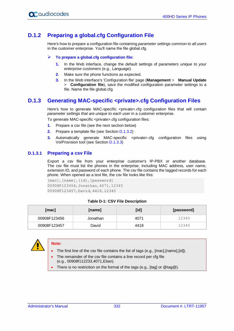
400HD Series IP Phones
Administrator's Manual 332 Document #: LTRT-11957
D.1.2 Preparing a global.cfg Configuration File Here's how to prepare a configuration file containing parameter settings common to all users in the customer enterprise. You'll name the file global.cfg.
To prepare a global.cfg configuration file: 1. In the Web interface, change the default settings of parameters unique to your
enterprise customers (e.g., Language). 2. Make sure the phone functions as expected. 3. In the Web interface's 'Configuration file' page (Management > Manual Update
> Configuration file), save the modified configuration parameter settings to a file. Name the file global.cfg.
D.1.3 Generating MAC-specific <private>.cfg Configuration Files Here's how to generate MAC-specific <private>.cfg configuration files that will contain parameter settings that are unique to each user in a customer enterprise. To generate MAC-specific <private>.cfg configuration files: 1. Prepare a csv file (see the next section below) 2. Prepare a template file (see Section D.1.3.2) 3. Automatically generate MAC-specific <private>.cfg configuration files using
VoIProvision tool (see Section D.1.3.3)
D.1.3.1 Preparing a csv File Export a csv file from your enterprise customer's IP-PBX or another database. The csv file must list the phones in the enterprise, including MAC address, user name, extension ID, and password of each phone. The csv file contains the tagged records for each phone. When opened as a text file, the csv file looks like this: [mac],[name],[id],[password] 00908F123456,Jonathan,4071,12345 00908F123457,David,4418,12345
Table D-1: CSV File Description
[mac] [name] [id] [password]
00908F123456 Jonathan 4071 12345
00908F123457 David 4418 12345
Note:
• The first line of the csv file contains the list of tags (e.g., [mac],[name],[id]). • The remainder of the csv file contains a line record per cfg file
(e.g., 00908f112233,4071,Eitan). • There is no restriction on the format of the tags (e.g., [tag] or @tag@).
Administrator's Manual D. Deploying AudioCodes IP Phones - Use Case
Version 2.2.16 333 400HD Series IP Phones
D.1.3.2 Preparing a Template File This section shows ISPs/integrators how to prepare a template file. Example of a template file: system/type=420HD voip/line/0/enabled=1 voip/line/0/id=[id] voip/line/0/auth_name=[name] voip/line/0/auth_password=[password] include global.cfg
Define in the template file parameter settings unique to each user. Parameter settings unique to each user are typically: Line Settings Personal Settings Phone Directory Note that the template file contains tags [ ]. The csv file that you prepared previously contains the values for these tags. You'll later use AudioCodes' VoIProvision tool to read the template file, replace the tags with values pulled from the csv file, and automatically generate MAC-specific <private>.cfg configuration files. Note also that the template file contains include functions to link to other files. In the example above, the function include global.cfg pulls all parameter settings common to all users from the global.cfg file you prepared previously. You can include links to specific configuration files, for example: system/type=420HD include 420HD_<MAC>_voip.cfg include vlan_conf.cfg include network_conf.cfg include provisioning_conf.cfg
You can also include URL paths to files in other locations (FTP, TFTP, HTTP, or HTTPS), for example: system/type=420HD include http://10.10.10.10/420HD_<MAC>_voip.cfg include https://remote-pc/vlan_conf.cfg include tftp://10.10.10.10/420HD_<MAC>_network.cfg include ftp://remote-pc/provisioning_conf.cfg
Note: If no URL is provided in the template file, the files are retrieved according to the provisioning information (e.g., DHCP Option 160 or 66/67).

400HD Series IP Phones
Administrator's Manual 334 Document #: LTRT-11957
D.1.3.3 Using AudioCodes' VoIProvision Tool Here's how to automatically generate multiple MAC-specific <private>.cfg files using AudioCodes' VoIProvision tool. The tool generates a separate cfg file for each phone in the customer enterprise.
To automatically generate MAC-specific <private>.cfg files: 1. Place AudioCodes' VoIProvision tool (VoIProvision.exe) in a folder on your pc. 2. Place the global.cfg configuration file that you prepared, together with the csv file and
the template file, in the same folder. 3. Run the VoIProvision exe; the tool automatically generates the <private>.cfg files.
USAGE: VoIProvision <csv file><template file><.cfg file>
Note: AudioCodes' VoIProvision tool can run on both Linux and Windows platforms. The tool initially parses the csv file to generate the list of tags. The tool then reads each line record of values in the csv file and for each line record, does this:
• Parses the line record to create a list of values • Opens the template file • Generates the cfg file name and creates a new cfg file • Reads the template file, associates the mapped tags with actual values from the csv
file, and writes the result to the cfg file • Closes the cfg file and template file
Example of an automatically generated MAC-specific file: system/type=420HD voip/line/0/enabled=1 voip/line/0/id=56832432 voip/line/0/auth_name=3423fdwer2tre voip/line/0/auth_password=123456 include global.cfg
The generated configuration (cfg) files use a similar format to the template file only the tags are replaced with the values read by the VoIProvision tool from the csv file. The tag in the csv file which defines the MAC address is used as the cfg file name.
D.1.3.3.1 Creating Manually a <private>.cfg Configuration File You can manually create a <private>.cfg configuration file using a standard ASCII, text-based program such as Notepad. The file name must be the phone's MAC address: <phone's MAC address>.cfg. The syntax of the configuration file is as follows: <parameter name>=<value>
Ensure that: No spaces are on either side of the equals (=) sign Each parameter is on a new line Below is an example of part of a configuration file: system/type=440HD voip/line/0/enabled=1 voip/line/0/id=1234 voip/line/0/description=440HD voip/line/0/auth_name=1234 voip/line/0/auth_password=4321
Administrator's Manual D. Deploying AudioCodes IP Phones - Use Case
Version 2.2.16 335 400HD Series IP Phones
D.2 Preparing the DHCP Server to Automatically Provision Phones To prepare the DHCP server:
• Configure DHCP OPTION 160 on the DHCP server. Point the DHCP server to the URL of the configuration files on the HTTP server. Use the string <MAC> For example: http://192.168.2.1/;440HD_<MAC>_conf.cfg
D.3 Making Sure Phones are Correctly Provisioned To make sure the phones are correctly provisioned:
1. Connect one of the phones to the IP network and power supply. 2. Follow the status displayed on the screen. Make sure the phone received an IP
address and is upgrading the configuration. 3. The phone reboots with the new configuration. 4. Make sure that all functionalities are functioning flawlessly, e.g., that the phone can
make VoIP calls.

400HD Series IP Phones
Administrator's Manual 336 Document #: LTRT-11957
This page is intentionally left blank.
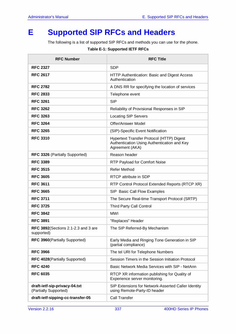
Administrator's Manual E. Supported SIP RFCs and Headers
Version 2.2.16 337 400HD Series IP Phones
E Supported SIP RFCs and Headers The following is a list of supported SIP RFCs and methods you can use for the phone.
Table E-1: Supported IETF RFCs
RFC Number RFC Title
RFC 2327 SDP
RFC 2617 HTTP Authentication: Basic and Digest Access Authentication
RFC 2782 A DNS RR for specifying the location of services
RFC 2833 Telephone event
RFC 3261 SIP
RFC 3262 Reliability of Provisional Responses in SIP
RFC 3263 Locating SIP Servers
RFC 3264 Offer/Answer Model
RFC 3265 (SIP)-Specific Event Notification
RFC 3310 Hypertext Transfer Protocol (HTTP) Digest Authentication Using Authentication and Key Agreement (AKA)
RFC 3326 (Partially Supported) Reason header
RFC 3389 RTP Payload for Comfort Noise
RFC 3515 Refer Method
RFC 3605 RTCP attribute in SDP
RFC 3611 RTP Control Protocol Extended Reports (RTCP XR)
RFC 3665 SIP Basic Call Flow Examples
RFC 3711 The Secure Real-time Transport Protocol (SRTP)
RFC 3725 Third Party Call Control
RFC 3842 MWI
RFC 3891 "Replaces" Header
RFC 3892(Sections 2.1-2.3 and 3 are supported)
The SIP Referred-By Mechanism
RFC 3960(Partially Supported) Early Media and Ringing Tone Generation in SIP (partial compliance)
RFC 3966 The tel URI for Telephone Numbers
RFC 4028(Partially Supported) Session Timers in the Session Initiation Protocol
RFC 4240 Basic Network Media Services with SIP - NetAnn
RFC 6035 RTCP XR information publishing for Quality of Experience server monitoring.
draft-ietf-sip-privacy-04.txt (Partially Supported)
SIP Extensions for Network-Asserted Caller Identity using Remote-Party-ID header
draft-ietf-sipping-cc-transfer-05 Call Transfer
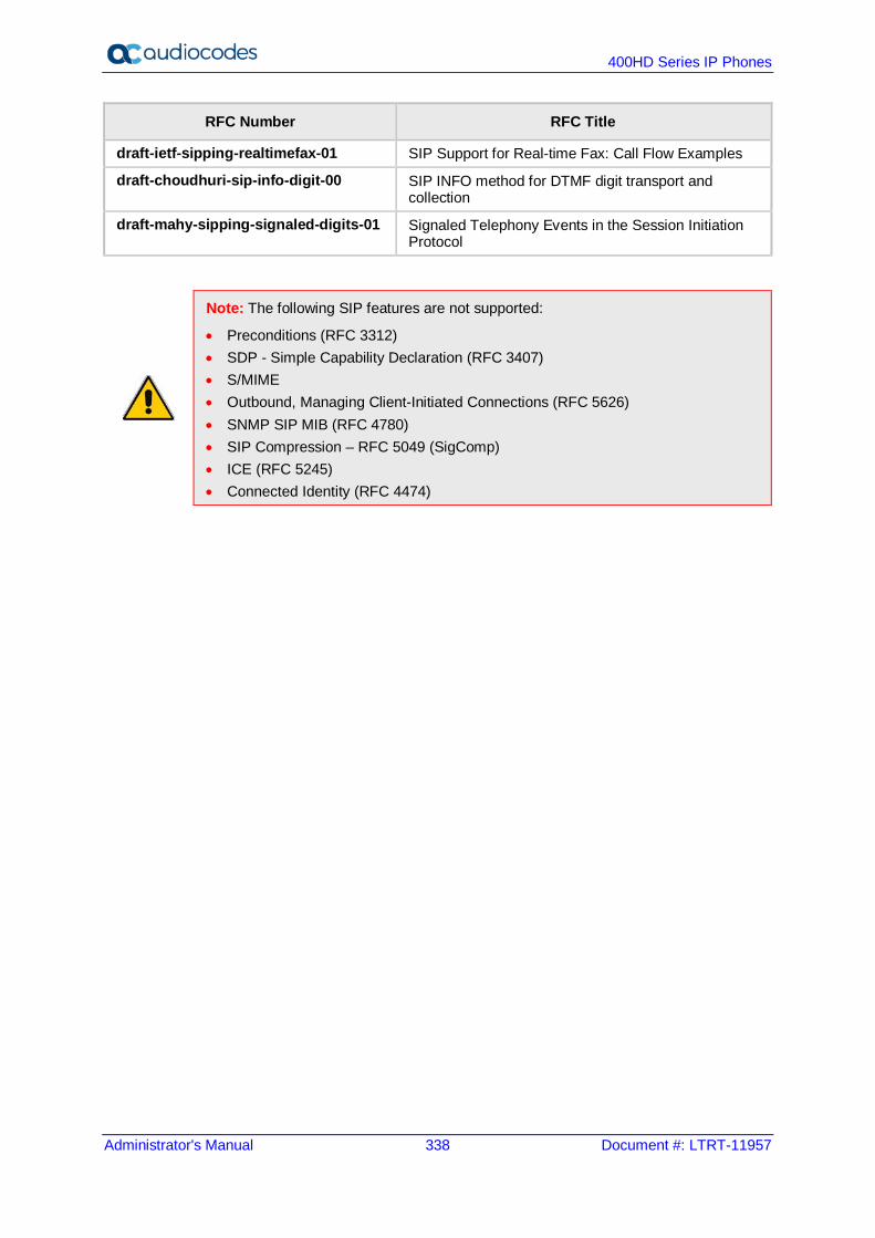
400HD Series IP Phones
Administrator's Manual 338 Document #: LTRT-11957
RFC Number RFC Title
draft-ietf-sipping-realtimefax-01 SIP Support for Real-time Fax: Call Flow Examples
draft-choudhuri-sip-info-digit-00 SIP INFO method for DTMF digit transport and collection
draft-mahy-sipping-signaled-digits-01 Signaled Telephony Events in the Session Initiation Protocol
Note: The following SIP features are not supported:
• Preconditions (RFC 3312) • SDP - Simple Capability Declaration (RFC 3407) • S/MIME • Outbound, Managing Client-Initiated Connections (RFC 5626) • SNMP SIP MIB (RFC 4780) • SIP Compression – RFC 5049 (SigComp) • ICE (RFC 5245) • Connected Identity (RFC 4474)
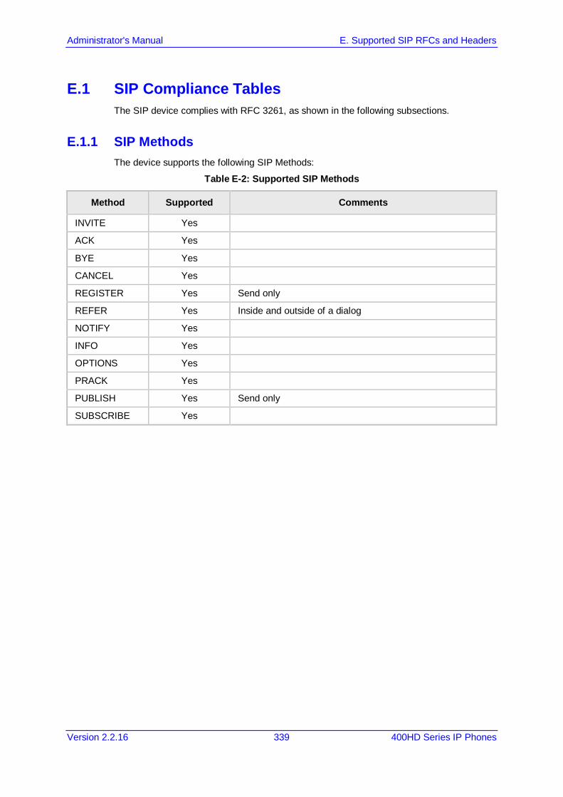
Administrator's Manual E. Supported SIP RFCs and Headers
Version 2.2.16 339 400HD Series IP Phones
E.1 SIP Compliance Tables The SIP device complies with RFC 3261, as shown in the following subsections.
E.1.1 SIP Methods The device supports the following SIP Methods:
Table E-2: Supported SIP Methods
Method Supported Comments
INVITE Yes
ACK Yes
BYE Yes
CANCEL Yes
REGISTER Yes Send only
REFER Yes Inside and outside of a dialog
NOTIFY Yes
INFO Yes
OPTIONS Yes
PRACK Yes
PUBLISH Yes Send only
SUBSCRIBE Yes
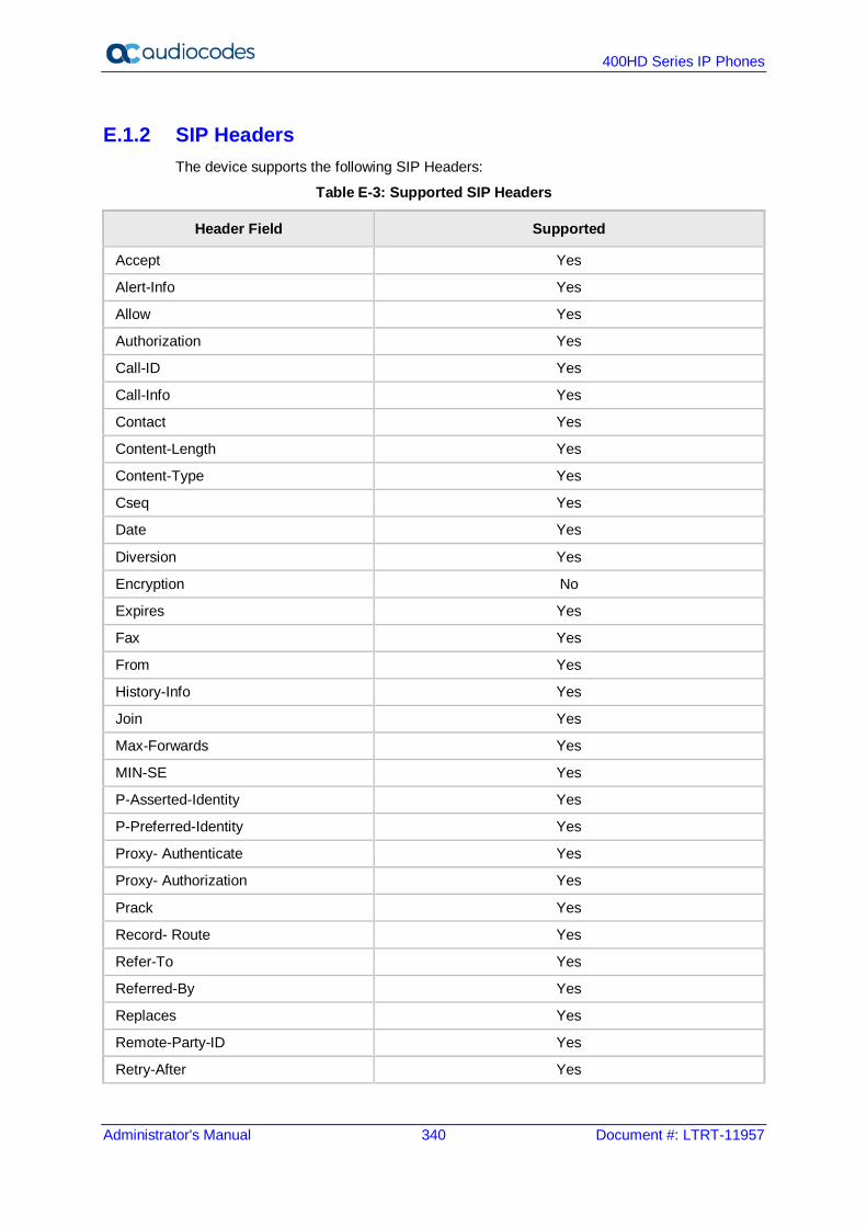
400HD Series IP Phones
Administrator's Manual 340 Document #: LTRT-11957
E.1.2 SIP Headers The device supports the following SIP Headers:
Table E-3: Supported SIP Headers
Header Field Supported
Accept Yes
Alert-Info Yes
Allow Yes
Authorization Yes
Call-ID Yes
Call-Info Yes
Contact Yes
Content-Length Yes
Content-Type Yes
Cseq Yes
Date Yes
Diversion Yes
Encryption No
Expires Yes
Fax Yes
From Yes
History-Info Yes
Join Yes
Max-Forwards Yes
MIN-SE Yes
P-Asserted-Identity Yes
P-Preferred-Identity Yes
Proxy- Authenticate Yes
Proxy- Authorization Yes
Prack Yes
Record- Route Yes
Refer-To Yes
Referred-By Yes
Replaces Yes
Remote-Party-ID Yes
Retry-After Yes
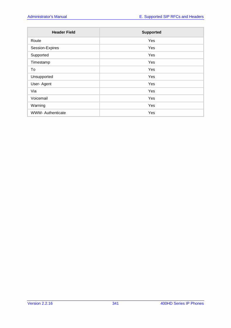
Administrator's Manual E. Supported SIP RFCs and Headers
Version 2.2.16 341 400HD Series IP Phones
Header Field Supported
Route Yes
Session-Expires Yes
Supported Yes
Timestamp Yes
To Yes
Unsupported Yes
User- Agent Yes
Via Yes
Voicemail Yes
Warning Yes
WWW- Authenticate Yes

400HD Series IP Phones
Administrator's Manual 342 Document #: LTRT-11957
This page is intentionally left blank.
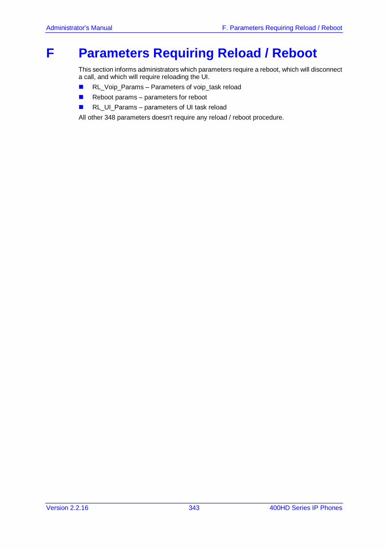
Administrator's Manual F. Parameters Requiring Reload / Reboot
Version 2.2.16 343 400HD Series IP Phones
F Parameters Requiring Reload / Reboot This section informs administrators which parameters require a reboot, which will disconnect a call, and which will require reloading the UI. RL_Voip_Params – Parameters of voip_task reload Reboot params – parameters for reboot RL_UI_Params – parameters of UI task reload All other 348 parameters doesn't require any reload / reboot procedure.

400HD Series IP Phones
Administrator's Manual 344 Document #: LTRT-11957
This page is intentionally left blank.
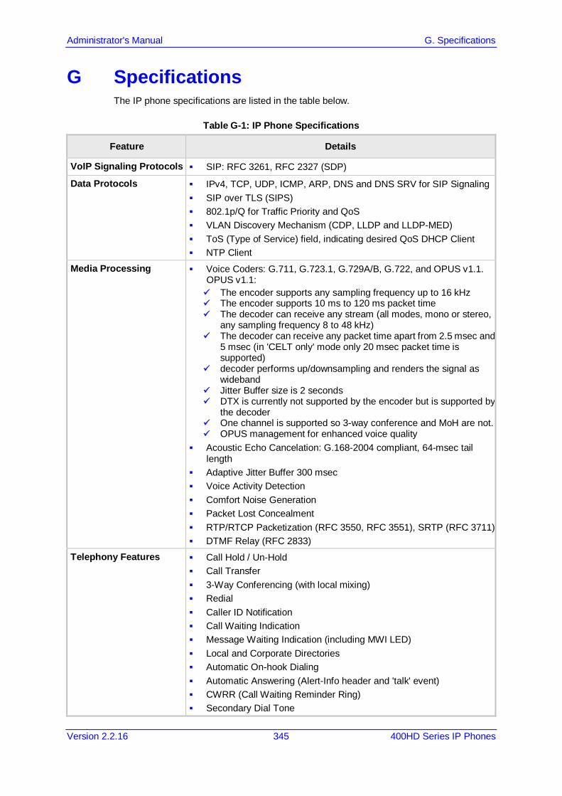
Administrator's Manual G. Specifications
Version 2.2.16 345 400HD Series IP Phones
G Specifications The IP phone specifications are listed in the table below.
Table G-1: IP Phone Specifications
Feature Details
VoIP Signaling Protocols SIP: RFC 3261, RFC 2327 (SDP)
Data Protocols IPv4, TCP, UDP, ICMP, ARP, DNS and DNS SRV for SIP Signaling SIP over TLS (SIPS) 802.1p/Q for Traffic Priority and QoS VLAN Discovery Mechanism (CDP, LLDP and LLDP-MED) ToS (Type of Service) field, indicating desired QoS DHCP Client NTP Client
Media Processing Voice Coders: G.711, G.723.1, G.729A/B, G.722, and OPUS v1.1. OPUS v1.1: The encoder supports any sampling frequency up to 16 kHz The encoder supports 10 ms to 120 ms packet time The decoder can receive any stream (all modes, mono or stereo,
any sampling frequency 8 to 48 kHz) The decoder can receive any packet time apart from 2.5 msec and
5 msec (in 'CELT only' mode only 20 msec packet time is supported)
decoder performs up/downsampling and renders the signal as wideband
Jitter Buffer size is 2 seconds DTX is currently not supported by the encoder but is supported by
the decoder One channel is supported so 3-way conference and MoH are not. OPUS management for enhanced voice quality
Acoustic Echo Cancelation: G.168-2004 compliant, 64-msec tail length
Adaptive Jitter Buffer 300 msec Voice Activity Detection Comfort Noise Generation Packet Lost Concealment RTP/RTCP Packetization (RFC 3550, RFC 3551), SRTP (RFC 3711) DTMF Relay (RFC 2833)
Telephony Features Call Hold / Un-Hold Call Transfer 3-Way Conferencing (with local mixing) Redial Caller ID Notification Call Waiting Indication Message Waiting Indication (including MWI LED) Local and Corporate Directories Automatic On-hook Dialing Automatic Answering (Alert-Info header and 'talk' event) CWRR (Call Waiting Reminder Ring) Secondary Dial Tone
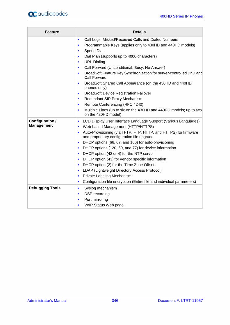
400HD Series IP Phones
Administrator's Manual 346 Document #: LTRT-11957
Feature Details
Call Logs: Missed/Received Calls and Dialed Numbers Programmable Keys (applies only to 430HD and 440HD models) Speed Dial Dial Plan (supports up to 4000 characters) URL Dialing Call Forward (Unconditional, Busy, No Answer) BroadSoft Feature Key Synchronization for server-controlled DnD and
Call Forward BroadSoft Shared Call Appearance (on the 430HD and 440HD
phones only) BroadSoft Device Registration Failover Redundant SIP Proxy Mechanism Remote Conferencing (RFC 4240) Multiple Lines (up to six on the 430HD and 440HD models; up to two
on the 420HD model) Configuration / Management
LCD Display User Interface Language Support (Various Languages) Web-based Management (HTTP/HTTPS) Auto-Provisioning (via TFTP, FTP, HTTP, and HTTPS) for firmware
and proprietary configuration file upgrade DHCP options (66, 67, and 160) for auto-provisioning DHCP options (120, 60, and 77) for device information DHCP option (42 or 4) for the NTP server DHCP option (43) for vendor specific information DHCP option (2) for the Time Zone Offset LDAP (Lightweight Directory Access Protocol) Private Labeling Mechanism Configuration file encryption (Entire file and individual parameters)
Debugging Tools Syslog mechanism DSP recording Port mirroring VoIP Status Web page

Administrator's Manual G. Specifications
Version 2.2.16 347 400HD Series IP Phones
Feature Details
Hardware LCD screen: Graphic LCD (128 X 48) (420HD model) Graphic LCD (256x12) (430HD and 440HD models)
BLF screen: (only applies to the 440HD model) Graphic LCD (60x376) monochrome
Connectors interfaces: 2 x RJ-45 ports (10/100BaseT Ethernet) for WAN and LAN RJ-9 port (jack) for Headset RJ-9 port (jack) for Handset USB interface for USB headset support RJ-11 interface for DHSG
Kensington lock Mounting: Wall and desktop mounting options One angle for desktop mount, another angle for wall mount
GbE support Power: DC jack adapter 12V Power supply AC 100 ~ 240V PoE: IEEE802.3af
Keys: 4 x softkeys VOICE MAIL message hotkey 4-way navigation keys with ENTER Key MENU REDIAL HOLD MUTE TRANSFER VOLUME control key HEADSET SPEAKER
Supported Headsets
For the comprehensive list of Jabra headsets, see the Jabra Headset Compatibility Guide For the comprehensive list of Plantronics headsets, see https://compatibility.plantronics.com/deskphone These include: Jabra UC-150 Jabra Speak 510+ Jabra Speak 410 Jabra MOTION OFFICE Jabra PRO 9470 Jabra Evolve Series 20, 30, 40, 75, 80 Microsoft LX-3000 Plantronics C-310M Plantronics C-320M Plantronics HW720 Plantronics Blackwire Series 300, 325, 510, 520, 710 Jabra Pro 920 EHS wireless headset Jabra Pro 9450 EHS wireless headset Axtel

400HD Series IP Phones
Administrator's Manual 348 Document #: LTRT-11957
This page is intentionally left blank.
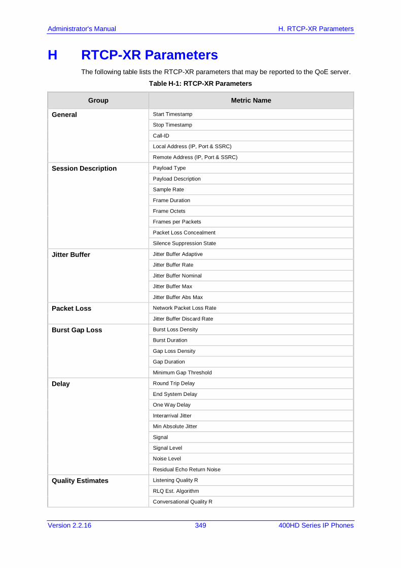
Administrator's Manual H. RTCP-XR Parameters
Version 2.2.16 349 400HD Series IP Phones
H RTCP-XR Parameters The following table lists the RTCP-XR parameters that may be reported to the QoE server.
Table H-1: RTCP-XR Parameters
Group Metric Name
General Start Timestamp
Stop Timestamp
Call-ID
Local Address (IP, Port & SSRC)
Remote Address (IP, Port & SSRC)
Session Description Payload Type
Payload Description
Sample Rate
Frame Duration
Frame Octets
Frames per Packets
Packet Loss Concealment
Silence Suppression State
Jitter Buffer Jitter Buffer Adaptive
Jitter Buffer Rate
Jitter Buffer Nominal
Jitter Buffer Max
Jitter Buffer Abs Max
Packet Loss Network Packet Loss Rate
Jitter Buffer Discard Rate
Burst Gap Loss Burst Loss Density
Burst Duration
Gap Loss Density
Gap Duration
Minimum Gap Threshold
Delay Round Trip Delay
End System Delay
One Way Delay
Interarrival Jitter
Min Absolute Jitter
Signal
Signal Level
Noise Level
Residual Echo Return Noise
Quality Estimates Listening Quality R
RLQ Est. Algorithm
Conversational Quality R
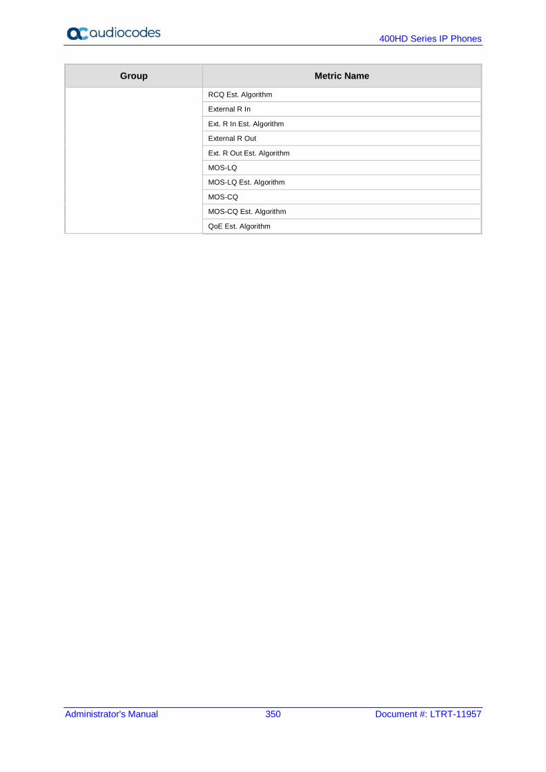
400HD Series IP Phones
Administrator's Manual 350 Document #: LTRT-11957
Group Metric Name
RCQ Est. Algorithm
External R In
Ext. R In Est. Algorithm
External R Out
Ext. R Out Est. Algorithm
MOS-LQ
MOS-LQ Est. Algorithm
MOS-CQ
MOS-CQ Est. Algorithm
QoE Est. Algorithm

Administrator's Manual I. Example SIP - PUBLISH Message
Version 2.2.16 351 400HD Series IP Phones
I Example SIP - PUBLISH Message This appendix displays an example SIP PUBLISH message extracted from RFC 6035. RTCP-XR values are found under the message body. PUBLISH sip:[email protected] SIP/2.0 Via: SIP/2.0/UDP pc22.example.org;branch=z9hG4bK3343d7 Max-Forwards: 70 To: <sip:[email protected]> From: Alice <sip:[email protected]>;tag=a3343df32 Call-ID: 1890463548 CSeq: 4331 PUBLISH Allow: INVITE, ACK, CANCEL, OPTIONS, BYE, REFER, SUBSCRIBE, NOTIFY Event: vq-rtcpxr Accept: application/sdp, message/sipfrag Content-Type: application/vq-rtcpxr Content-Length: ... VQSessionReport: CallTerm CallID: 6dg37f1890463 LocalID: Alice <sip:[email protected]> RemoteID: Bill <sip:[email protected]> OrigID: Alice <sip:[email protected]> LocalGroup: example-phone-55671 RemoteGroup: example-gateway-09871 LocalAddr: IP=10.10.1.100 PORT=5000 SSRC=1a3b5c7d LocalMAC: 00:1f:5b:cc:21:0f RemoteAddr:IP=11.1.1.150 PORT=5002 SSRC=0x2468abcd RemoteMAC: 00:26:08:8e:95:02 LocalMetrics: Timestamps:START=2004-10-10T18:23:43Z STOP=2004-10-01T18:26:02Z SessionDesc:PT=18 PD=G729 SR=8000 FD=20 FO=20 FPP=2 PPS=50 FMTP="annexb=no" PLC=3 SSUP=on JitterBuffer:JBA=3 JBR=2 JBN=40 JBM=80 JBX=120 PacketLoss:NLR=5.0 JDR=2.0 BurstGapLoss:BLD=0 BD=0 GLD=2.0 GD=500 GMIN=16 Delay:RTD=200 ESD=140 SOWD=200 IAJ=2 MAJ=10 Signal:SL=-21 NL=-50 RERL=55 QualityEst:RLQ=90 RCQ=85 EXTRI=90 MOSLQ=4.2 MOSCQ=4.3 QoEEstAlg=P.564 RemoteMetrics: Timestamps:START=2004-10-10T18:23:43Z STOP=2004-10-01T18:26:02Z SessionDesc:PT=18 PD=G729 SR=8000 FD=20 FO=20 FPP=2 PPS=50 FMTP="annexb=no" PLC=3 SSUP=on JitterBuffer:JBA=3 JBR=2 JBN=40 JBM=80 JBX=120 PacketLoss:NLR=5.0 JDR=2.0 BurstGapLoss:BLD=0 BD=0 GLD=2.0 GD=500 GMIN=16 Delay:RTD=200 ESD=140 SOWD=200 IAJ=2 MAJ=10 Signal:SL=-21 NL=-45 RERL=55 QualityEst:RLQ=90 RCQ=85 MOSLQ=4.3 MOSCQ=4.2 QoEEstAlg=P.564 DialogID:[email protected];to-tag=8472761; from-tag=9123dh311
400HD Series IP Phones
Administrator's Manual 352 Document #: LTRT-11957
Note: Remote Metrics are not supported in this version.

Administrator's Manual I. Example SIP - PUBLISH Message
Version 2.2.16 353 400HD Series IP Phones
This page is intentionally left blank.
International Headquarters 1 Hayarden Street, Airport City Lod 7019900, Israel Tel: +972-3-976-4000 Fax: +972-3-976-4040 AudioCodes Inc. 27 World’s Fair Drive, Somerset, NJ 08873 Tel: +1-732-469-0880 Fax: +1-732-469-2298 Contact us: https://www.audiocodes.com/corporate/offices-worldwide Website: https://www.audiocodes.com/ ©2018 AudioCodes Ltd. All rights reserved. AudioCodes, AC, HD VoIP, HD VoIP Sounds Better, IPmedia, Mediant, MediaPack, What’s Inside Matters, OSN, SmartTAP, User Management Pack, VMAS, VoIPerfect, VoIPerfectHD, Your Gateway To VoIP, 3GX, VocaNom, AudioCodes One Voice and CloudBond are trademarks or registered trademarks of AudioCodes Limited. All other products or trademarks are property of their respective owners. Product specifications are subject to change without notice. Document #: LTRT-11957