R oolle e roff itthhe ossii lliccaa nnaannooppaarttiicclee ...

Research Project EASA.2012/2
MASH - Metallurgical Assessment ofStandard Hardware
easa.europa.eu

Disclaimer
This study has been carried out for the European Aviation Safety Agency by an external organization and expresses the opinion of the organization undertaking the study. It is provided for information purposes only and the views expressed in the study have not been adopted, endorsed or in any way approved by the European Aviation Safety Agency. Consequently it should not be relied upon as a statement, as any form of warranty, representation, undertaking, contractual, or other commitment binding in law upon the European Aviation Safety Agency.
Ownership of all copyright and other intellectual property rights in this material including any documentation, data and technical information, remains vested to the European Aviation Safety Agency. All logo, copyrights, trademarks, and registered trademarks that may be contained within are the property of their respective owners.
Reproduction of this study, in whole or in part, is permitted under the condition that the full body of this Disclaimer remains clearly and visibly affixed at all times with such reproduced part.

RESTRICTED - COMMERCIAL
Harpur Hill, Buxton Derbyshire, SK17 9JN T: +44 (0)1298 218000 F: +44 (0)1298 218590 W: www.hsl.gov.uk
European Aviation Safety Agency - Metallurgical
Assessment of Standard Hardware, EASA reference E2.2012.C.02.
ES/13/49
Lead Author: S Joel, PhD Contributing Authors:
Technical Reviewer: P F Heyes Editorial Reviewer: P McCann
Report Authorised for Issue By: N Corlett, PhD Date Authorised: 2 August 2013

RESTRICTED - COMMERCIAL
DISTRIBUTION Mr Werner Kleine-Beek Research Project Manager, Safety Analysis and Research Dept.,
Executive Directorate (European Aviation Safety Agency) Dr Lionel Tauszig (European Aviation Safety Agency) Dr Wolfgang Hoffman (European Aviation Safety Agency) Dr Andrew Curran HSL (electronic copy) Dr Nigel Moss HSL (electronic copy) Dr Nigel Corlett HSL (electronic copy) Dr Stephen Joel HSL (electronic copy) Registry File HSL HSL Archive HSL
© Crown copyright (2013)
Report Authorised for Issue by: N Corlett PhD Date of issue: 2 August 2013 Project Manager: R Brentnall Technical Reviewer(s): P F Heyes Editorial Reviewer: P McCann HSL Project Number: PE04696
PRIVACY MARKING: RESTRICTED: COMMERCIAL This report and the work it describes were undertaken by the Health and Safety Laboratory under contract to European Aviation Safety Agency. Its contents, including any opinions and/or conclusion expressed or recommendations made, do not necessarily reflect policy or views of the Health and Safety Executive.

RESTRICTED - COMMERCIAL
iii
ACKNOWLEDGEMENTS This study entitled “Metallurgical Assessment of Standard Hardware” (MASH) was carried out with funding provided by the European Aviation Safety Agency. The author would like to also acknowledge the assistance and expertise offered by colleagues at HSL, particularly the assistance of Mr Martin Roff during the non-destructive dye penetrant examination. The advice provided and services arranged by Mr Julian Whitehead at Precision Processing Services Ltd with regard to stripping of the coating from the samples were invaluable in allowing an accurate chemical analysis of said samples and is duly acknowledged.

RESTRICTED - COMMERCIAL
CONTENTS
1 INTRODUCTION ..................................................................................... 1 1.1 METHODOLOGY/TEST PLAN ................................................................ 1
2 LABORATORY EXAMINATION ............................................................. 2 2.1 ITEMS SUBMITTED FOR EXAMINATION. ............................................. 2
3 ASSESSMENT OF FINDINGS .............................................................. 17
4 CONCLUSIONS .................................................................................... 19
5 APPENDICES ....................................................................................... 20 5.1 Appendix A ............................................................................................ 21 5.2 Appendix B ............................................................................................ 22 5.3 Appendix C – chemical analysis certificate ............................................ 23
6 REFERENCES ...................................................................................... 24

RESTRICTED - COMMERCIAL
vi
EXECUTIVE SUMMARY
Objectives
The study detailed in this report was carried out under the auspices of the European Aviation Safety Agency (EASA) in accordance with their “Invitation to Negotiate E.2.2012.NP.03” and subsequently the agreement drawn up between EASA and the Health and Safety Laboratory (HSL), Harpur Hill, Buxton, Derbyshire, UK, SK17 9JN. The agreement had the EASA designation EASA.E2.2012.C.02. The majority of the work was carried out at the premises of the HSL
This study had been commissioned by EASA as a result of concerns regarding the integrity of aviation standard hardware nuts. These standard hardware parts are being used on fixed wing aircraft, rotorcraft, engines, propeller attachments and appliances certified by EASA. The assumptions made during certification rely on adherence to certain standards. Deviations from these standards may result in premature failure of a fastener or fasteners with consequences at the aircraft level. The present investigation aims at verifying the adherence of some provided National Aerospace Standard (NAS) 1291 self-locking nuts to the standard.
Main Findings
1) The nuts had been coated with a bonded dry film lubricant coating.
2) Dry film lubricants are permitted by the relevant Standard.
3) In the author’s opinion, it is likely that the coating would have met the specifications in NASM25027.
4) The nuts had not been cadmium plated.
5) The discontinuities seen on the nut flanges were mechanical damage caused by external contact not flaws introduced during the forming process.
6) In the author’s opinion, it was not thought that the visible damage seen would have had a detrimental effect on the functionality of the nuts.
7) Fluorescent dye-penetrant non-destructive examination revealed some minor forming flaws on the bearing surfaces of the nuts. It was not thought that these flaws would have had a detrimental effect on the functionality of the nuts.
8) Fluorescent dye-penetrant non-destructive examination did not reveal any significant defects.
9) Crimping marks on the nut faces were considered to satisfy the requirements of clause 3.5 in NASM25027 in that they blended smoothly without abrupt change.
10) The minor forming burrs on the threads of the nuts were not thought to be detrimental to the functionality of the nuts.
11) Six nuts failed the dimensional requirements of NAS1291. Despite this, in the author’s opinion, the nuts met the requirements of the Standard, in spirit if not to the letter.
12) The chemical composition of the nuts sampled apparently satisfied the requirements of grade A286 corrosion resistant steel.

RESTRICTED - COMMERCIAL
vii
13) The torque testing did not produce any cracking of any sort in any of the nuts. Therefore, the nuts met the requirements of the civil and military aviation specifications for the wrench torque test.
14) No cracking of any sort was identified in any of the nuts during this study.
Recommendations
A second similar test programme could be carried out on standard hardware nuts manufactured from other materials permitted by NAS1291. In particularly an investigation into the conformance of cadmium plated alloy steel nuts to the Standard could be of value.
As it is understood that all the supplied nuts came from one manufacturer further studies could be undertaken on nuts, made to the NAS1291 specification by other manufacturers.
It would be useful to extend the study to larger sample sizes to improve the statistical significance of any findings.

RESTRICTED - COMMERCIAL
1
1 INTRODUCTION
The study detailed in this report was carried out under the auspices of the European Aviation Safety Agency (EASA) in accordance with their “Invitation to Negotiate E.2.2012.NP.03” and subsequently the agreement drawn up between EASA and the Health and Safety Laboratory (HSL), Harpur Hill, Buxton, Derbyshire, UK, SK17 9JN. The agreement had the EASA designation EASA.E2.2012.C.02. The majority of the work was carried out at the premises of the HSL; the sub-tasks of coating stripping and chemical analysis were sub-contracted to external companies as described later in the report.
This study had been commissioned by EASA as a result of concerns regarding the integrity of aviation standard hardware nuts. This standard hardware is being used on fixed wing aircraft, rotorcraft, engines, propeller attachments and appliances certified by EASA. The assumptions made during certification rely on adherence to a certain standard. Deviations from the standard may result in premature failure of a fastener or fasteners with consequences at the aircraft level. The present investigation aims at verifying the adherence of the supplied National Aerospace Standard (NAS)1291 self-locking nuts to the standard. A batch of eighteen self-locking nuts designed and nominally manufactured to this Standard was submitted to HSL by EASA. Of these, three examples had been identified by EASA as demonstrating evidence of surface irregularities. The remaining fifteen were classed as having no obvious defects. The submitted nuts were to be examined for visual appearance (including non-destructive examination for pre-existing defects), dimensional conformance, hardness, ability to withstand operating torque (torque testing) and chemical composition with respect to the Standard. If any cracking of the samples were to be introduced by the torque testing then the cracked items would be examined to determine the nature and cause of the failure.
1.1 METHODOLOGY/TEST PLAN
Initially a test plan was drawn up in accordance with the original “Invitation to Negotiate E.2.2012.NP.03”, this test plan is summarised in Appendix A. Modifications to this original test plan are shown in green. The need for these modifications came about during the early stages of the study after two samples had been subjected to scanning electron microscopy and energy dispersive spectroscopy. The changes were discussed and agreed with EASA. Subsequently, as a result of interim findings made during the course of the investigation, further modifications were made to the test plan. The final programme of investigations carried out (referenced to their original task numbers in the first test plan) is shown in Appendix B. Unless specified otherwise, all of the photographic images used in this report were taken by the author. Where measurements are quoted to two decimal places they had been made with calibrated instruments and the precision of these measurements was ±0.01mm. Otherwise, measurements were made with rules and steel tape measures and, therefore, are for indication only.

RESTRICTED - COMMERCIAL
2
2 LABORATORY EXAMINATION
2.1 ITEMS SUBMITTED FOR EXAMINATION. The initial visual examination included all eighteen of the submitted samples. The three items which had been separated out before receipt at the HSL were identified as A15394-1 to 3. The other fifteen nuts were arbitrarily numbered HSL#1 to #15. It was understood that all eighteen nuts came from the same batch. The supplied nuts were reported to be to NAS1291C3M grade and of thread size .1900-32UNJF-3B i.e. nominally .1900inch (4.826mm) in diameter with 32 threads per inch (0.794mm thread pitch). The C3M in the designation indicates that the nuts should have been made from corrosion resistant steel of A286 (UNS S66286) grade. This steel is an iron-nickel chromium alloy with additions of molybdenum and titanium. It is a high temperature alloy which is reported to maintain good strength and oxidation resistance at temperatures up to 7000C.
2.1.1 Visual Examination (Tasks 1a, 1b-i, 1b-ii, 1b-iii and 5-i). All the samples received were generally similar in appearance. Figure 1 below shows angled views of three typical examples.
Figure 1. Typical examples of submitted items.
These examples include; one of the separated nuts, which had a gouge/deformation in the flange, see the right hand quadrant of A15394-1, a nut of relatively good appearance (HSL #4), and a nut with a poor quality appearance (HSL#8). The marks on the upper flat of #4 and the right hand flat of #8 are the physical manifestations of the crimping operation carried out to produce the deformation in the threadform that produces a self-locking action. Such distortion and tool marks are permitted although they “shall blend smoothly without abrupt change” according to the National Aerospace Standard NASM25027 (rev.1) “Nuts, self-locking, 2500F, 4500F, and 8000F”. This Standard is referenced in NAS1291 as the procurement specification for these nuts. Although there were some differences in the appearance of these marks across the batch of all eighteen nuts, in the author’s opinion they all satisfied this requirement of the Standard. All of the nuts had the letters “SD” in low-relief on one segment of the flange outer surface and the letter “C” in low-relief on the diametrically opposed flange segment. The “C” indicated that the nuts had been made from corrosion resistant steel. The letters “SD” have been assumed to be a manufacturer’s mark or code.
A15394-1 HSL#4 HSL#8

RESTRICTED - COMMERCIAL
3
Visually, all of the nuts were similar in appearance. What differences there were included: varying degrees of mechanical damage to the edges of the flange on individual nuts (nuts A15394 1-3 had noticeable examples of this damage), the appearance and depth of the marks left by the crimping of the top of the nut and the general appearance and evenness of the surface coating. Despite the variability of the crimp marks none of them appeared to be bad enough to discard the nuts on the grounds of the clause in the standard which stated that such marks “shall blend smoothly without abrupt change”. On a subjective basis and from the author’s experience, it was not thought that anything in the external appearance of the submitted nuts indicated that there would have been any problems with the functionality or fitness for purpose of any of the nuts. The internal threads of all the nuts were also similar in appearance and all appeared to be generally of good shape and well-formed. In some cases there were some minor examples of burring at the thread crowns and at thread starts. These were minor burrs which in the author’s opinion would not have affected the functionality or performance of the nuts Figure 2 shows the bearing surfaces of the same three nuts. The gouge/deformation in the flange of A15394-1 is clearly visible. All the flange edge damage seen on the eighteen nuts appeared to be mechanical damage resulting from external contact rather than defects arising from manufacture.
Figure 2. Bearing surfaces of example nuts.
The un-scored condition of the bearing surfaces of all eighteen nuts indicated that none of them had been used.
2.1.2 Dimensional Assessment (Task 5-iii). The dimensions of all eighteen nuts were measured using calibrated instruments and compared against the specified values in the diagram (reproduced in Figure 3) and the tables from National Aerospace Standard NAS1291 rev.13 which had been provided by the customer. The results of the dimensional analysis are given in Table 1 below, all values are in millimetres and the precision of the measurements is ±0.01mm. The values highlighted in yellow are borderline but actually compliant with respect to the specifications. Those values highlighted in red fall outside the specified range.
HSL#8 HSL#4 A15394-1

RESTRICTED - COMMERCIAL
4
Figure 3. Diagram of standard hardware from NAS1291 rev.13.
Table 1. Dimensions of submitted NAS1291-C3M nuts.
PE04696 - NAS 1291 C3M Nut # A B C ØW ØD ØF Annular bearing
area NAS1291 3.91-
4.78 6.17-6.40 7.03
min 8.38 max
4.83-5.59
7.36 min
5.56mm2 min - 11.15mm2 max
A15394-1 4.71 6.20, 6.30, 6.32 7.20, 7.09, 7.13 8.15 5.56 7.97 7.57 A15394-2 4.70 6.20, 6.35, 6.32 7.21, 7.08, 7.06 8.08 5.52 7.85 7.32 A15394-3 4.68 6.24, 6.38, 6.40 7.23, 7.15, 7.13 8.09 5.42 7.85 7.63
1 4.67 6.24, 6.37, 6.31 7.28, 7.09, 7.14 8.23 5.60 8.06 7.73 2 4.69 6.22, 6.33, 6.37 7.28, 7.26, 7.19 8.29 5.70 8.26 8.04 3 4.73 6.21, 6.37, 6.36 7.22, 7.08, 7.09 8.06 5.52 7.80 7.16 4 4.71 6.20, 6.29, 6.34 7.15, 7.08, 7.10 8.08 5.47 7.80 7.32 5 4.67 6.26, 6.37, 6.36 7.32, 7.18, 7.18 8.22 5.68 8.19 7.89 6 4.69 6.17, 6.32, 6.31 7.15, 7.10, 7.08 8.10 5.43 7.92 7.82 7 4. 67 6.26, 6.35, 6.33 7.24, 7.15, 7.14 8.11 5.55 7.90 7.38 8 4.60 6.23, 6.36, 6.36 7.27, 7.15, 7.19 8.30 5.44 8.12 8.42 9 4.68 6.17, 6.28, 6.31 7.21, 7.05, 7.09 8.08 5.59 7.85 7.10
10 4.69 6.21, 6.32, 6.33 7.22, 7.09, 7.11 8.06 5.51 7.84 7.32 11 4.68 6.20, 6.31, 6.29 7.19, 7.11, 7.12 8.08 5.60 7.76 6.79 12 4.63 6.25, 6.34, 6.35 7.33,7.18, 7.20 8.30 5.70 8.21 7.89 13 4.63 6.18, 6.30, 6.29 7.18, 7.07, 7.09 8.05 5.44 7.77 7.32 14 4.71 6.21, 6.34, 6.35 7.24, 7.09, 7.09 8.16 5.69 8.00 7.26 15 4.68 6.22, 6.34, 6.33 7.22, 7.07, 7.13 8.04 5.44 7.87 7.63
It can be seen from the red highlighted results that four of the submitted samples fail the dimensional requirements and another two only satisfy these requirements, with respect to the maximum value of diameter D (i.e. the inner diameter of the annular bearing surface), if measurement error is taken into account. It should be noted however, that despite this discrepancy the actual contact bearing areas of all the six samples are well within the wide range of contact bearing areas which can be calculated from the specified dimensions, see the area limits given in the final column of Table 1. The calculated annular bearing contact surface area in all cases (right hand column) was greater than the absolute minimum value that would have been permitted by the specified dimensions, i.e. 5.56mm2, see Figure 4 below

(G Whilspecion thof lonindica
2.1.3 As stmarkresist If thithat t(UNSresistone eand band/o This on nuthe nuimage
Green = max
st it is acknofication, it ise performanngitudinal cation of a lac
3 Prel
tated, the iniked with a "Ctant steel, on
s steel was fthese nuts wS-S66286) istance that woexample fromby energy dior nature of a
preliminary ut HSL#8, fout, nor was te of the exter
Figure 4ximum possi
owledged ths not thoughce of the nutracking repock of quality
liminary SE
itial visual eC" indicatine of the mate
found to be cwould have bs a high nickeould not reqm the nuts sispersive speany surface c
scanning eleound no indicthere any indrnal surface
RESTRICT
4. Range of ble contact a
at these resut that these mts or would horted in othecontrol whic
EM and ED
examination g that they erials describ
compliant wbeen subjecteel content (~
quire any furshould be exectroscopy (Ecoating, i.e. w
ectron microcation of any
dication of thof this nut w
ØD
ØD
TED - COM
5
f bearing suarea, Orange
ults take the minimal failihave played aer examples ch is rigorou
DS (Tasks 3
had revealehad been m
bed in the NA
with the specied to cadmiu
~25%) alloy wrther surfacexamined in tEDS) to assewas it cadmiu
oscopy and ey cracking o
he presence owith the EDS
Dmax.
Dmin.
MMERCIAL
urface contae = minimum
six samplesings would hany contributof these nu
us enough to
3a-iii and 3b
d that all ofmanufactured
AS1291 Stan
ification thenum plating. with very go
e corrosion pthe Scanningess the surfaum plating o
nergy dispern the bearing
of any cadmispectrum fro
ØW
ØF
act areas: acceptable
s out of confhave had anytory role in p
uts. The resudetect such f
b).
f the submittfrom the C
ndard.
n it was thouThe specifie
ood high tempprotection. Itg Electron Mce conditionr some other
rsive spectrog surface or um plating. Fom the indic
W= ØFmax.
Fmin.
contact area
formance wiy significant producing thults are a pofailings.
ted nuts hadCRES or corr
ught very uned A-286 ma
mperature corrt was decide
Microscope (n and the prer coating.
oscopy, carriethe upper paFigure 5 sho
cated area.
a).
ith the effect e type
ossible
d been rosion
nlikely aterial rosion
ed that SEM)
esence
ed out arts of ows an
RESTRICTED - COMMERCIAL
6
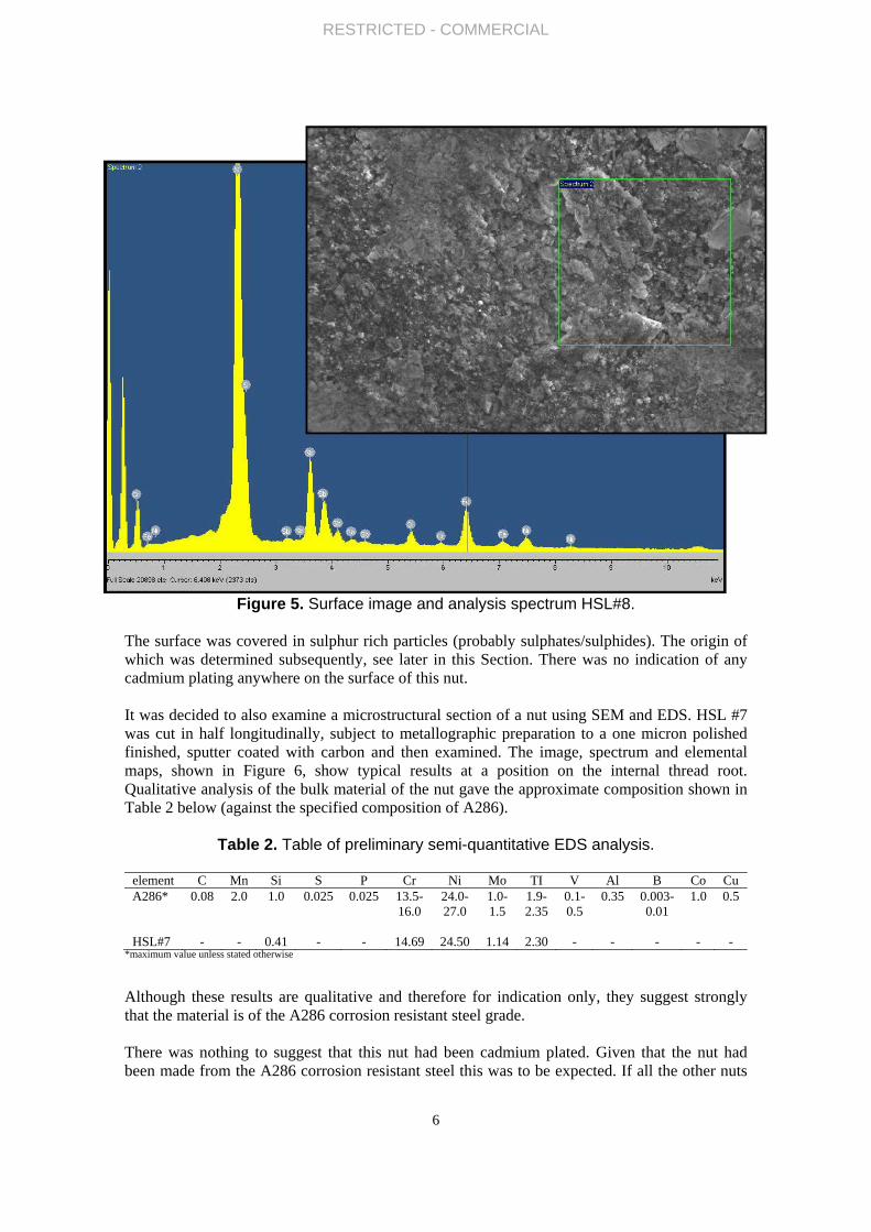
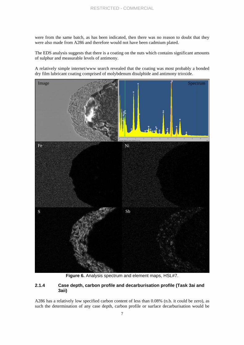
Figure 5. Surface image and analysis spectrum HSL#8. The surface was covered in sulphur rich particles (probably sulphates/sulphides). The origin of which was determined subsequently, see later in this Section. There was no indication of any cadmium plating anywhere on the surface of this nut. It was decided to also examine a microstructural section of a nut using SEM and EDS. HSL #7 was cut in half longitudinally, subject to metallographic preparation to a one micron polished finished, sputter coated with carbon and then examined. The image, spectrum and elemental maps, shown in Figure 6, show typical results at a position on the internal thread root. Qualitative analysis of the bulk material of the nut gave the approximate composition shown in Table 2 below (against the specified composition of A286).
Table 2. Table of preliminary semi-quantitative EDS analysis.
element C Mn Si S P Cr Ni Mo TI V Al B Co Cu A286* 0.08 2.0 1.0 0.025 0.025 13.5-
16.0 24.0- 27.0
1.0- 1.5
1.9- 2.35
0.1- 0.5
0.35 0.003- 0.01
1.0 0.5
HSL#7 - - 0.41 - - 14.69 24.50 1.14 2.30 - - - - -
*maximum value unless stated otherwise
Although these results are qualitative and therefore for indication only, they suggest strongly that the material is of the A286 corrosion resistant steel grade. There was nothing to suggest that this nut had been cadmium plated. Given that the nut had been made from the A286 corrosion resistant steel this was to be expected. If all the other nuts
RESTRICTED - COMMERCIAL
7
were from the same batch, as has been indicated, then there was no reason to doubt that they were also made from A286 and therefore would not have been cadmium plated. The EDS analysis suggests that there is a coating on the nuts which contains significant amounts of sulphur and measurable levels of antimony. A relatively simple internet/www search revealed that the coating was most probably a bonded dry film lubricant coating comprised of molybdenum disulphide and antimony trioxide.
Figure 6. Analysis spectrum and element maps, HSL#7.
2.1.4 Case depth, carbon profile and decarburisation profile (Task 3ai and 3aii)
A286 has a relatively low specified carbon content of less than 0.08% (n.b. it could be zero), as such the determination of any case depth, carbon profile or surface decarburisation would be
Image Spectrum
Fe Ni
Sb S

RESTRICTED - COMMERCIAL
8
very difficult and represent such little variation in the properties of the components that in the author’s opinion attempting to do this would have been of no value. It was therefore agreed with EASA that this part of the original test methodology could be excluded.
2.1.5 Bulk Chemical Analysis (Task 3b and 5ii) It was apparent that the bonded dry film lubricant coating would have to be removed before a complete bulk chemical analysis of the bolt material could be carried out. Research revealed that the best method to achieve the necessary coating removal would be molten salt cleaning and one company was identified that could perform this operation. This company was Precision Processing Services Limited (hereafter PPSL), 60 Clooney Road, Londonderry BT47 6TR Northern Ireland. Mr Julian Whitehead, the Chemical, Technical and R&D Engineer at this company developed and proposed a multi stage cleaning process to achieve the necessary level of coating removal, on the stated understanding that there would be “no degradation or modification of the stainless steel substrate which could provide erroneous results on testing” (e-mail from Mr Whitehead to the author, dated 08/03/2013). This stripping process involved:-
• An initial chemical process using a chelating agent (Ethylenediaminetetraacetic acid [EDTA] or equivalent) to remove / breakout the heavy metal salts from the coating,
• A secondary alkaline chemical process to dissolve out any remaining antimony trioxide from the coating, and to loosen / free the molybdenum disulphide part,
• A final molten salt oxidation to remove trace coating from the component.
Four nuts from the batch of fifteen were selected (#1, #3, #13 and #15) and submitted to PPSL for stripping. When the nuts had been returned from PPSL they were submitted to Element Materials Technology, Nursery Street, Sheffield S3 8GB for bulk chemical analysis. As a result of the small size of the individual nuts Element Materials Technology advised that the only way to obtain a full analysis of all the specified elements in grade A286 corrosion resistant steel would be to carry out differing elemental analyses on different nuts as follows:-
• Sample #1 ICP OES for majority of specified elements.
• Sample #3 carbon and sulphur.
• Samples #13 & #15 boron. Therefore, the complete analysis given in Table 3 below is a compilation of results from the four samples. It cannot be guarantee that this is a certifiable analysis for any individual nut. However, given that the nuts are all reported to have come from the same batch it is believed that it is reasonable to accept the analysis as truly representative of the chemical composition of the nuts. The results are shown against the requirements of grade A286 corrosion resistant steel in Table 3.
Table 3. Chemical analysis results. element C Mn Si S P Cr Ni Mo TI V Al B Co Cu A286* 0.08 2.0 1.0 0.025 0.02
5 13.5- 16.0
24.0-
27.0
1.0- 1.5
1.9- 2.35
0.1- 0.5
0.3
5
0.003- 0.01
1.0
0.5
Analysed
0.041
0.35
0.07
<0.003
<0.01
13.88
27.0 1.23
2.35
0.22
0.19
0.0034
0.5
0.24

RESTRICTED - COMMERCIAL
9
samples *maximum value unless stated otherwise
The chemical analysis certificate is appended to this report Appendix C. From the analyses performed the nuts most probably satisfy the chemical composition of grade A286 corrosion resistant steel.
2.1.6 Fluorescent dye penetrant examination.(Task 1c) As the nuts were all A286 corrosion resistant nuts then NASM25027 indicated (at clause 4.5.4.2) that the correct NDE technique to use should be fluorescent dye penetrant inspection, not magnetic particle inspection (mpi) as specified in the contract for this work. Therefore, with the agreement of EASA, fluorescent dye penetrant inspection was substituted for magnetic particle inspection for this task. All the remaining thirteen samples (HSL #7, #1, #3, #13, #15 having been used for metallography and chemical analysis) were subjected to dye penetrant testing of their bearing surfaces carried out following as far as possible the guidelines in BS EN 571-1:1997 “Non-destructive testing – Penetrant testing” and the BS EN ISO 3452-1:2013 “Non-destructive testing – Penetrant testing”. The fluorescent dye penetrant used was Chemetall Britemor 446. Visual examination and photography was carried out with the assistance of Mr Martin Roff, a Senior Scientist in the Occupational Hygiene Unit at HSL. Of the 13 samples examined only three showed any visual features that might subjectively have been interpreted as indications of defects and as such required further investigation. These were samples #5, #8 and #11. It was decided that these samples plus sample A15392-1 would have their bearing surfaces polished and examined for microscopical cracking or other defects prior to them being subjected to the angularity check and torque testing. It was acknowledged that this might have had some effect with regard to the angularity testing but, given the possibility of the presence of defects, it was thought more useful to check for the latter first. The results of the dye penetrant testing on these four samples are given below.
Figure 7. Nut A15394-1 UV light.

RESTRICTED - COMMERCIAL
10
Figure 7, there were no obvious indications on this sample; it had been selected randomly for polishing to represent the A15394 group of three. No defects or cracking were revealed by the subsequent polishing and microscopical examination.
Figure 8. Nut #5 UV light. Figure 8, there were some possible (tenuous) indications in the upper left quadrant and at the bottom of image. Polishing and microscopical examination subsequently revealed a very fine, shallow, circumferential manufacturing flaw over a 600 arc at the mid-width position on the flange bearing surface. This had not been revealed by the dye penetrant. No other defects or cracks were seen. The circumferential flaw has been attributed to the forming process for the nut flange. It is normal to (i.e. at 900 to) the longitudinal cracking that had been reported in other instances and therefore is thought to be of limited, if any, significance
Possible indication
Possible indication
Diffuse circumferential indications

RESTRICTED - COMMERCIAL
11
Figure 9. Nut #8 UV light. Figure 9, there was a possible radial indication in upper right quadrant, also a diffuse circumferential indication at mid-width position on the flange bearing surface. After polishing the circumferential defect was found to be a manufacturing flaw as seen in #5, only more extensive (over ~1800 of arc) and slightly deeper. This nut was mounted in resin and polished again; the extra polishing completely removed all traces of this flaw. No other defects or cracking were seen.
Figure 10. Nut #8 normal light. Figure 10, in normal light the upper right defect can be seen to be a step in the coating. Some indications of the circumferential manufacturing flaw can be seen visually.
circumferential indications
Possible indication
Possible indication

RESTRICTED - COMMERCIAL
12
Figure 11. Nut #11 UV light. Figure 11, there was one possible fine indication in the lower right quadrant, however polishing and microscopical examination revealed no defects or cracking. There was no circumferential manufacturing flaw on this sample.
2.1.7 Bearing Surface Angularity test in accordance with NAS1291 and NASM25027 (Task 1b-iv).
The bearing surface angularity test was carried out using test jigs manufactured in the HSL Engineering Safety Unit workshop. The design of the test jig is shown in Figure 12 below. The required UNJF thread was machined on the spigot extending from the body and a parallel finely ground washer was used to give clearance above the radius at the end of the thread. The latter meant that the full extent of the thread on the nut was being used during both the angularity test and the subsequent torque tests
Figure 12. Test rig with parallel ground washer and sectioned nut (HSL #7).
Possible indication
RESTRICTED - COMMERCIAL
13
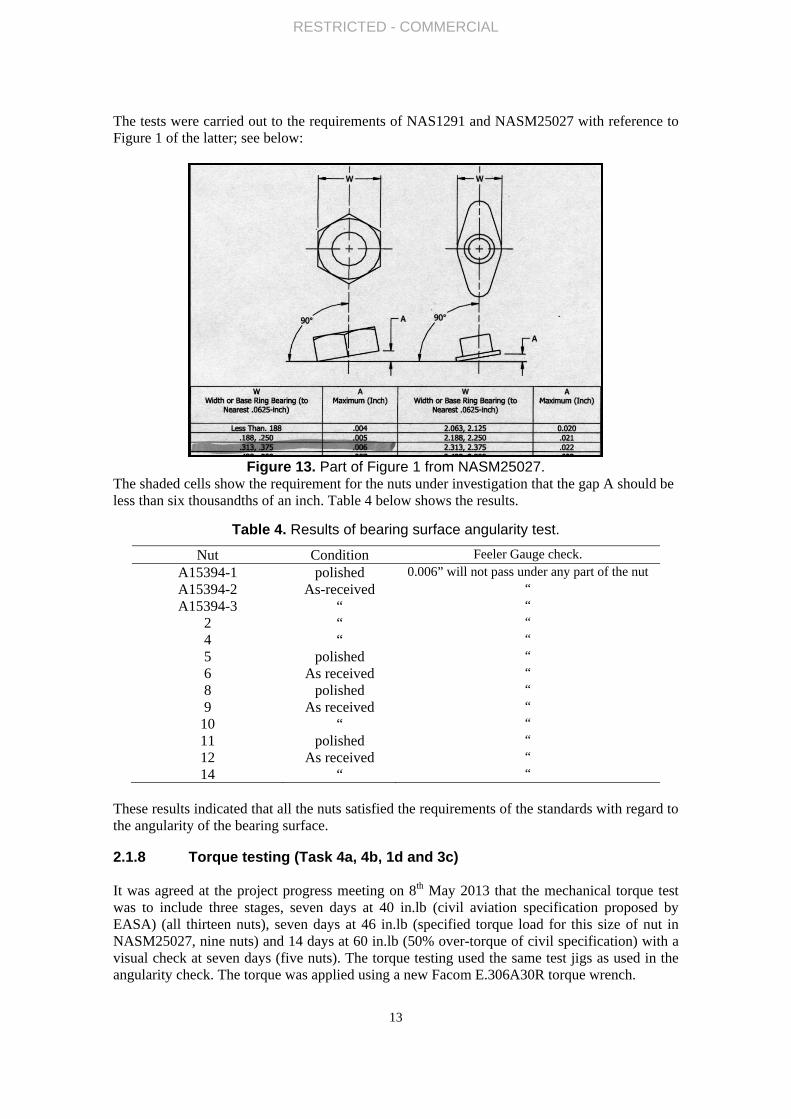
The tests were carried out to the requirements of NAS1291 and NASM25027 with reference to Figure 1 of the latter; see below:
Figure 13. Part of Figure 1 from NASM25027.
The shaded cells show the requirement for the nuts under investigation that the gap A should be less than six thousandths of an inch. Table 4 below shows the results.
Table 4. Results of bearing surface angularity test.
Nut Condition Feeler Gauge check. A15394-1 polished 0.006” will not pass under any part of the nut A15394-2 As-received “ A15394-3 “ “
2 “ “ 4 “ “ 5 polished “ 6 As received “ 8 polished “ 9 As received “
10 “ “ 11 polished “ 12 As received “ 14 “ “
These results indicated that all the nuts satisfied the requirements of the standards with regard to the angularity of the bearing surface.
2.1.8 Torque testing (Task 4a, 4b, 1d and 3c) It was agreed at the project progress meeting on 8th May 2013 that the mechanical torque test was to include three stages, seven days at 40 in.lb (civil aviation specification proposed by EASA) (all thirteen nuts), seven days at 46 in.lb (specified torque load for this size of nut in NASM25027, nine nuts) and 14 days at 60 in.lb (50% over-torque of civil specification) with a visual check at seven days (five nuts). The torque testing used the same test jigs as used in the angularity check. The torque was applied using a new Facom E.306A30R torque wrench.

Folloexternfour n#8, #referenot re The rpoweload)were referenot renuts. The rrigs fcrackplacereferepolishNonerende
2.1.9
Althocheckthe to6507gave nuts. hardnA153highe12HVHSL#
Har
dnes
s H
V10
owing the firnal surfaces nuts which h
#11), were uence AHUT.eveal any cra
remaining nuer optical mi again revearemoved fro
ence AHUUeveal any cr
remaining fivfor a further
king. The fine. The final ence AHUVhed bearing e of the thirered tasks 1e
9 Hard
ough no hardk the uniformorque testing-2: 1998 “Man unusual Three readin
ness found w394-2. The loest was 427HV10 hardnes#14, a graphi
A
rst of these tof all thirtee
had been pounfastened an. Their beariacking or oth
uts were theicroscopical aled no signom the test ri. Their beariracking or ot
ve nuts werer fifteen day
nal external ifive nuts we. Microscopisurfaces of arteen nuts su, 5-iv and 5-
dness Test
dness value imity of the sg were subje
Metallic materange of harngs were takwas 341HVowest indiviHV10 on nuss points onical represen
A1 A2 A
RESTRICT
three stages;en nuts, whillished previond mounted ng surfaces
her defects on
en torqued toexaminations of crackingigs and mouning surfaces ther defects
e increased toys. An exterinspection afere mountedical examinaany of these fubjected to v, unnecessa
ting
s specified fsupplied nutsected to Vickerials – Vickrdness valueken on each
V10 for nut idual hardneut HSL#9. Tn A15394-2 ntation of the
A3 #2
TED - COM
14
; low power lst still undeously, follow
d in a singlewere then ren the bearing
o 46in.lb (mn of the exteg. Four nutsnted in a singwere then reon the polis
o 60in.lb torrnal inspectiofter fifteen dd in a singleation did not five nuts. torque testi
ary.
for the CRESs the thirteenkers hardneskers hardneses both betwnut bearing HSL#2, the
ess measuremThe lowest ra
and the hige results is pr
#4 #5
MMERCIAL
optical micrer load, reveawing the dyee resin moune-polished. Mg surfaces of
military spec.ernal surfaces (A15394-3gle resin moue-polished. Mshed bearing
rque (150% con after sev
days also foue resin mounreveal any cr
ng suffered
S nuts in NAn mounted ass testing in ss test Part
ween differensurface and
e highest avment was 31ange of hardghest range resented in F
#6 #8
roscopical exaled no signse penetrant tent with the lMicroscopica
any of these
). After the s of the nineHSL#2, HS
unt with the Microscopica
surfaces of
civil spec.) aen days rev
und that no cnt with the lracking or ot
any crackin
AS1291, as anand polished
accordance 1. Test meth
nt nuts and inaveraged. Th
verage was 47HV10 on A
dness on anywas 86HV
igure 14, bel
#9 #10
examination s of crackingest (A15394laboratory sal examinatioe four nuts.
second stage nuts (still SL#6 and Hlaboratory s
al examinatiof any of thes
and left on thvealed no sigcracking had laboratory sther defects o
ng. This ou
n additional d samples us
with BS ENhod”. This tn some indiv
The lowest av402HV10 foA15394-3 any one sampl
V10 points olow.
#11 #12
of the g. The -1 #5, ample on did
ge low under SL#9) ample on did e four
he test gns of taken
ample on the
tcome
test to ed for
N ISO testing vidual verage or nut nd the le was on nut
2 #14

RESTRICTED - COMMERCIAL
15
(A1, A2 and A3 represent A15394-1, A15394-2 and A15394-3)
Figure 14. Hardness test results.
At this point in the investigation no apparent trend in the hardness values that could be associated with any features on the nuts, or the testing regimes they had been subjected to, had been identified. Some factors which may have had an effect were differential degrees of mechanical deformation in the flange area of the nuts during manufacture, different strain hardening effects produced during thread forming/cutting and, but much less likely, variable strain hardening produced during the torque testing. In order to resolve this; microscopical metallographic examination was carried out on the nuts mounted in laboratory sample AHUT, see section 2.1.10.
2.1.10 Metallography (Task 3c)
The nuts in sample AHUT (A15394-1, HSL#5, HSL#8 and HSL#11) were examined
microscopically after etching in mixed acids (nitric, acetic and hydrochloric). This examination revealed that the structure consisted of deformed austenite containing variable levels of deformation twinning. Figure 15 shows the structure variation across the width of nut HSL#8.
Figure 15. Structure variation across bearing surface of HSL#8.
It was apparent that the metal had undergone a greater degree of deformation toward the outer, flanged diameter, resulting in a higher concentration of deformation twinning. This would be expected as the flange would require more deformation during the forming process.

RESTRICTED - COMMERCIAL
16
A consequence of this variation in microstructure would be a significant variation in the hardness of the metal across the bearing surface. The hardness testing carried out above was done on the polished bearing surfaces (to obtain the best accuracy with regard to individual hardness measurements) where the variations in the microstructure could not be identified. The variation in position of hardness indentation positions on a single sample is shown in Figure 16 which shows two of the hardness impressions in nut A15394-1.
Figure 16. Hardness impressions in bearing surface of A15394.
Figure 15 shows a hardness impression wholly within the greatly deformed flange microstructure; Figure 16 shows impressions in the less deformed core metal and in the border between the two regions. This variation in the hardness locations would account, in itself, for the variations seen in the hardness values reported above.
This examination showed that no meaningful single hardness value could be attributed to the finished nut and therefore that hardness measurement could not be seen as a reliable indicator of manufacturing quality.
The metallographic examination has also shown that, given the variable deformation to all of the microstructure, a meaningful grain size assessment would not have been possible.
It was understood from information provided by the customer that nuts made to the alternate “steel” grade permitted by NAS1291 would have been heat treated after forming to produce a uniform transformed and tempered structure which would have a uniform hardness. Therefore it is reasonable that NAS1291 should have a hardness requirement for “steel” nuts (nuts to be <Rc49 hardness), but not for the CRES grade nuts which are in the worked condition and have microstructural variations as described above.

RESTRICTED - COMMERCIAL
17
3 ASSESSMENT OF FINDINGS
This assessment of findings should only be considered in light of the fact that the eighteen nuts examined probably do not represent a statistically valid sample. Nevertheless, this study has produced sufficient information for some tentative conclusions to be drawn. At the outset of this study the author read several aviation warning notices and reports (ref. 1-7) with regard to the failure of standard hardware nuts by longitudinal cracking. From this publically available literature it appears that most nut failures have been attributed to hydrogen embrittlement caused by poor cadmium plating and/or heat treatment procedures. However, the author has not seen reports on the metallurgical causes of all standard hardware failures. Therefore, it seemed reasonable to investigate the supplied samples for conformance to the relevant standards even though, as it transpired during the course of the study, they had not been cadmium plated.
The energy dispersive analysis performed on sample HSL#7 indicated that the nuts had been coated with a bonded dry film lubricant coating. Dry film lubricants are permitted by the relevant standards and the requirements for such coatings are detailed in NASM25027. It was out-with the scope of this study to determine if the coating would have satisfied the requirements of NASM25027 but in the author’s opinion it is likely that the coating would have met the specification.
There was nothing to indicate that the nuts had been cadmium plated at any stage during manufacture. There would be no requirement to cadmium plate nuts made from the corrosion resistant steel and NAS1291 does not require it.
There was some variability in the visual appearance of the nuts when they were received at the laboratory. Some of the variability appeared to be due to variations in the appearance of the lubricant coating. This lack of uniformity in surface appearance gave, in the author’s opinion, a false impression of a lack of quality between the nuts. The degrees of visual physical damage exhibited by the nuts also varied, however, in all circumstances low-power microscopical examination indicated that the damage was mechanical deformation caused by external contact. None of the damage appeared to be the result of problems during manufacture, there were no visible cracks, laps or folds arising from the manufacturing process. The dye-penetrant examination and subsequent microscopy did reveal the existence of minor shallow circumferential flaws on the bearing surfaces of some of the nuts that appeared to have been products of the forming process of the nut flange. These circumferential defects disappeared with light surface grinding and polishing and are not thought to give rise to any significant concerns with regard to the functionality of the nuts. The dye-penetrant examination did not reveal any significant defects.
The crimping marks on the nut faces were subjectively considered to satisfy the requirements of clause 3.5 in NASM25027 in that they blended smoothly without abrupt change.
The threads on the nuts had only minor burrs at the thread crown and on some thread starts, these were not thought to be detrimental to the functionality of the nuts.
There were four, possibly six, nuts where the same dimension failed the requirements of NAS1291. However, given that the incorrect dimension did not (in any of these six nuts) take the bearing surface area outside the permissible range, it is considered that this did not represent a valid reason to state that the nuts did not meet the requirements of the standard.
The chemical composition of the nuts sampled apparently satisfied the requirements of grade A286 corrosion resistant steel.
RESTRICTED - COMMERCIAL
18
The torque testing did not produce any cracking of any sort in any of the nuts. Therefore, the nuts met the requirements of the civil and military aviation specifications for the wrench torque test and continued to surpass these requirements up to an over-torque fifty per-cent greater than the civil aviation requirement. The nuts were stable and strong enough to withstand up to four weeks under load without showing any signs of cracking or suffering any “permanent deformation that may interfere with the use of a box or open end wrench”, the latter being the requirement of NASM25027.
To summarise the above, in the author’s opinion the supplied nuts met the dimensional, chemical composition, coating, and torque strength requirements of NAS1291 and NASM25027 where the latter is specified by the former. The samples examined and tested showed no inclination to undergo the same catastrophic longitudinal cracking failures that have been seen and reported in other standard hardware.

RESTRICTED - COMMERCIAL
19
4 CONCLUSIONS
From the findings of this study it is concluded that:
1) The nuts had been coated with a bonded dry film lubricant coating.
2) Dry film lubricants are permitted by the relevant Standard.
3) In the author’s opinion, it is likely that the coating would have met the specifications in NASM25027.
4) The nuts had not been cadmium plated.
5) The discontinuities seen on the nut flanges were most likely mechanical damage caused by external contact not flaws introduced during the forming process.
6) In the author’s opinion, it was not thought that the visible damage seen would have had a detrimental effect on the functionality of the nuts.
7) Fluorescent dye-penetrant non-destructive examination revealed some minor forming flaws on the bearing surfaces of the nuts. It was not thought that these flaws would have had a detrimental effect on the functionality of the nuts.
8) Fluorescent dye-penetrant non-destructive examination did not reveal any significant defects.
9) Crimping marks on the nut faces were considered to satisfy the requirements of clause 3.5 in NASM25027 in that they blended smoothly without abrupt change.
10) The minor forming burrs on the threads of the nuts were not thought to be detrimental to the functionality of the nuts.
11) Six nuts failed the dimensional requirements of NAS1291. Despite this, in the author’s opinion, the nuts met the requirements of the Standard, in spirit if not to the letter.
12) The chemical composition of the nuts sampled apparently satisfied the requirements of grade A286 corrosion resistant steel.
13) The torque testing did not produce any cracking of any sort in any of the nuts. Therefore, the nuts met the requirements of the civil and military aviation specifications for the wrench torque test.
14) No cracking of any sort was identified in any of the nuts during this study.
RESTRICTED - COMMERCIAL
20
5 APPENDICES

RESTRICTED - COMMERCIAL
21
5.1 APPENDIX A
EASA MASH Original Programme
Task Sub task Activity Modifications
1a Markings on hardware
1b i Visual assessment: surface condition
ii Visual assessment: thread quality
iii Visual assessment: discontinuities
iv Visual assessment: mechanical deformation Angularity check in accordance with NASM25027
1c Magnetic particle inspection Changed to fluorescent dye penetrant NDE, as per MASM25027.
Photography of above
1d Optical examination of polished bearing surface To be carried out after angularity test and torque (mechanical test) in combination with task 3c.
1e i Optical microscopy of fracture surfaces
ii SEM fractography
2 Selection for NDT and destructive tests
3a i Measurement of case depth Not meaningful with low carbon corrosion resistant steel therefore not performed.
ii Decarburisation measurement Not performed see comment above.
iii Conduct a coating/plating evaluation
3b Bulk chemical analysis Qualitative EDS carried out on one sample HSL#8, early in study.
3c Metallography ‐ determine grain size investigate if any micro‐cracking has occurred.
One sample HSL#7 examined metallographically early in study.
4a Design and manufacture rig for torque tests, Carry out torque test (7 days)
Extra variable of increasing torque levels during testing
4b Optical analysis of fractured components
5 i Description of components
ii Comparison of composition with Standards
iii Comparison of manufacturing quality with Standards
iv Comparison of failed and intact components
v Assessment of failure mechanism
vi Documentation of all results
6 Reporting
i Monthly reports
ii Intermediate reports x 2
iii Final study report
7 Meetings
7.1 Kick off meeting (Cologne)
7.2 Progress meeting (HSL)
7.3 Progress meeting (Video conference)
7.4 Final presentation (Cologne)

RESTRICTED - COMMERCIAL
22
5.2 APPENDIX B
EASA MASH Executed programme
Task Sub task Activity Comments
1a Markings on hardware Done
1b i Visual assessment: surface condition “
ii Visual assessment: thread quality “
iii Visual assessment: discontinuities “
iv Visual assessment: mechanical deformation “
1c Fluorescent dye‐penetrant NDE “
Photography of above “
1d Optical examination of polished bearing surface “
1e i Optical microscopy of fracture surfaces No longer applicable, no cracking.
ii SEM fractography “
2 Selection for NDT and destructive tests Done
3a i Measurement of case depth Not applicable, see section 2.1.4 ii Decarburisation measurement “
iii Conduct a coating/plating evaluation Done
3b Bulk chemical analysis “
3c Metallography ‐ determine grain size investigate if any micro‐cracking has occurred.
“
4a Design and manufacture rig for torque tests, Carry out torque test (7 days)
Done
4b Optical analysis of fractured components No longer applicable, no failures.
5 i Description of components Done
ii Comparison of composition with Standards “
iii Comparison of manufacturing quality with Standards “
iv Comparison of failed and intact components No longer applicable, no failures.
v Assessment of failure mechanism “
vi Documentation of all results Done (in report)
6 Reporting
i Monthly reports Done
ii Intermediate reports x 2 “
iii Final study report “
7 Meetings
7.1 Kick off meeting (Video conference) Done
7.2 Progress meeting (HSL) “
7.3 Progress meeting (Telephone conference) “
7.4 Final presentation (Cologne) “

RESTRICTED - COMMERCIAL
23
5.3 APPENDIX C – CHEMICAL ANALYSIS CERTIFICATE

RESTRICTED - COMMERCIAL
24
6 REFERENCES
1) Robinson Helicopter Company, R22 service letter SL-58 + R44 service letter SL-38 + R66 service letter SL-01, Issued 18 August 2011.
2) Bell Helicopter, Operation Safety Notice, GEN-11-43, Revision A Issued 16 September 2011.
3) Australian Government – Civil Aviation Safety Authority, Airworthiness Bulletin, AWB 14-002, Issued 12 October 2011.
4) Air Accident Investigation Board, AAIB Bulletin 7/2012, ref. EW/G2012/01/11.
5) EASA Safety Information Bulletin, SIB No 2012-06, Issued 22 March 2012.
6) Aviation Suppliers Association Web Log, EASA Investigates Cracking Standard Hardware, dated 26 April 2012.
7) EASA Safety Information Bulletin, SIB No 2012-06R1, Issued 07 August 2012.

Postal address Visiting address Tel Fax Mail Web