4 Foot/ 1200mm Aisle Width Net-Contain Aisle …...4 Foot/ 1200mm Aisle Width Net-Contain Aisle...
71
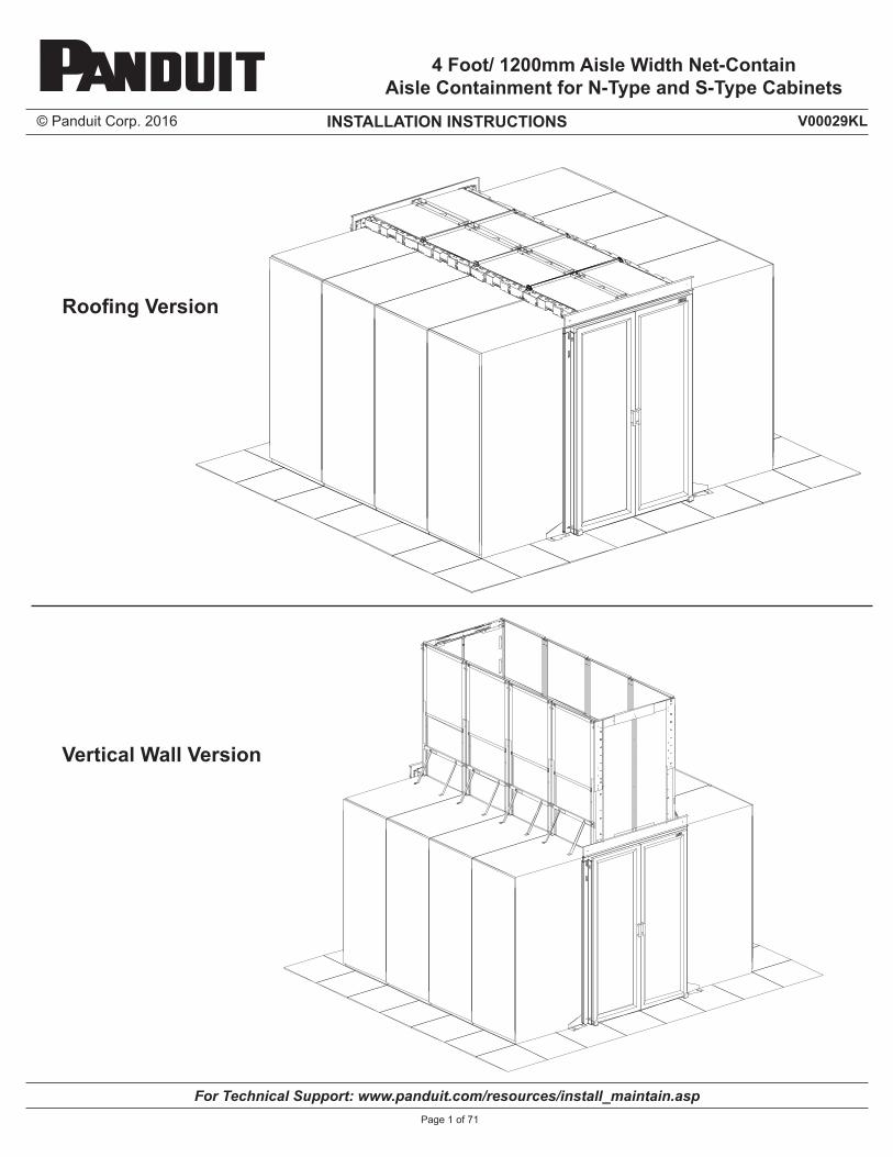
© Panduit Corp. 2016 INSTALLATION INSTRUCTIONS For Technical Support: www.panduit.com/resources/install_maintain.asp V00029KL Page 1 of 71 4 Foot/ 1200mm Aisle Width Net-Contain Aisle Containment for N-Type and S-Type Cabinets Roofing Version Vertical Wall Version
Transcript of 4 Foot/ 1200mm Aisle Width Net-Contain Aisle …...4 Foot/ 1200mm Aisle Width Net-Contain Aisle...
© Panduit Corp. 2016 INSTALLATION INSTRUCTIONS
For Technical Support: www.panduit.com/resources/install_maintain.asp
V00029KL
Page 1 of 71
4 Foot/ 1200mm Aisle Width Net-ContainAisle Containment for N-Type and S-Type Cabinets
Roofing Version
Vertical Wall Version
© Panduit Corp. 2016 INSTALLATION INSTRUCTIONS
For Technical Support: www.panduit.com/resources/install_maintain.asp
V00029KL
Page 2 of 71
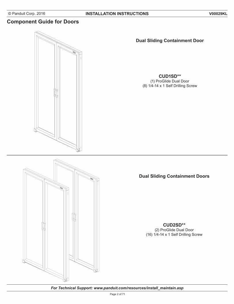
Dual Sliding Containment Door
Component Guide for Doors
CUD2SD** (2) ProGlide Dual Door
(16) 1/4-14 x 1 Self Drilling Screw
CUD1SD** (1) ProGlide Dual Door
(8) 1/4-14 x 1 Self Drilling Screw
Dual Sliding Containment Doors
© Panduit Corp. 2016 INSTALLATION INSTRUCTIONS
For Technical Support: www.panduit.com/resources/install_maintain.asp
V00029KL
Page 3 of 71
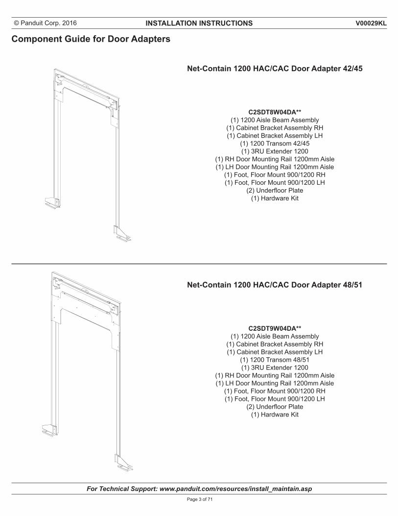
Component Guide for Door Adapters
C2SDT8W04DA** (1) 1200 Aisle Beam Assembly
(1) Cabinet Bracket Assembly RH (1) Cabinet Bracket Assembly LH
(1) 1200 Transom 42/45(1) 3RU Extender 1200
(1) RH Door Mounting Rail 1200mm Aisle (1) LH Door Mounting Rail 1200mm Aisle
(1) Foot, Floor Mount 900/1200 RH (1) Foot, Floor Mount 900/1200 LH
(2) Underfloor Plate (1) Hardware Kit
Net-Contain 1200 HAC/CAC Door Adapter 42/45
C2SDT9W04DA** (1) 1200 Aisle Beam Assembly
(1) Cabinet Bracket Assembly RH (1) Cabinet Bracket Assembly LH
(1) 1200 Transom 48/51(1) 3RU Extender 1200
(1) RH Door Mounting Rail 1200mm Aisle (1) LH Door Mounting Rail 1200mm Aisle
(1) Foot, Floor Mount 900/1200 RH (1) Foot, Floor Mount 900/1200 LH
(2) Underfloor Plate (1) Hardware Kit
Net-Contain 1200 HAC/CAC Door Adapter 48/51
© Panduit Corp. 2016 INSTALLATION INSTRUCTIONS
For Technical Support: www.panduit.com/resources/install_maintain.asp
V00029KL
Page 4 of 71
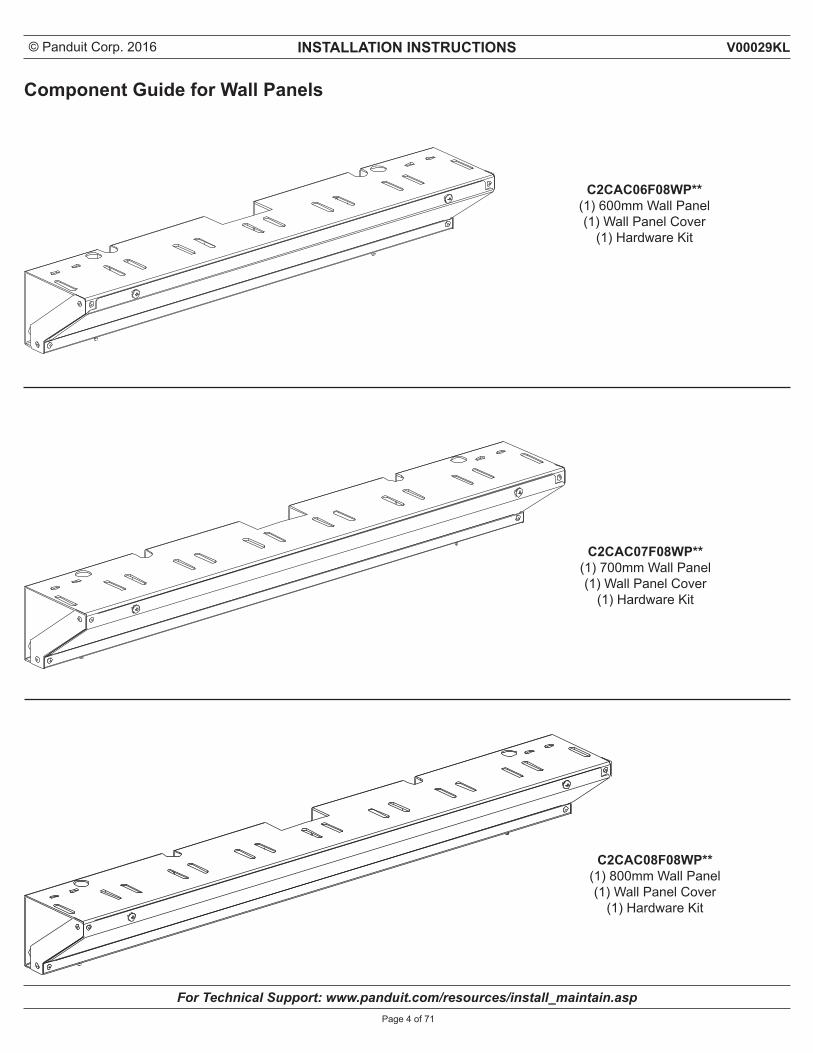
C2CAC06F08WP**(1) 600mm Wall Panel(1) Wall Panel Cover
(1) Hardware Kit
C2CAC07F08WP**(1) 700mm Wall Panel(1) Wall Panel Cover
(1) Hardware Kit
C2CAC08F08WP**(1) 800mm Wall Panel(1) Wall Panel Cover
(1) Hardware Kit
Component Guide for Wall Panels
© Panduit Corp. 2016 INSTALLATION INSTRUCTIONS
For Technical Support: www.panduit.com/resources/install_maintain.asp
V00029KL
Page 5 of 71
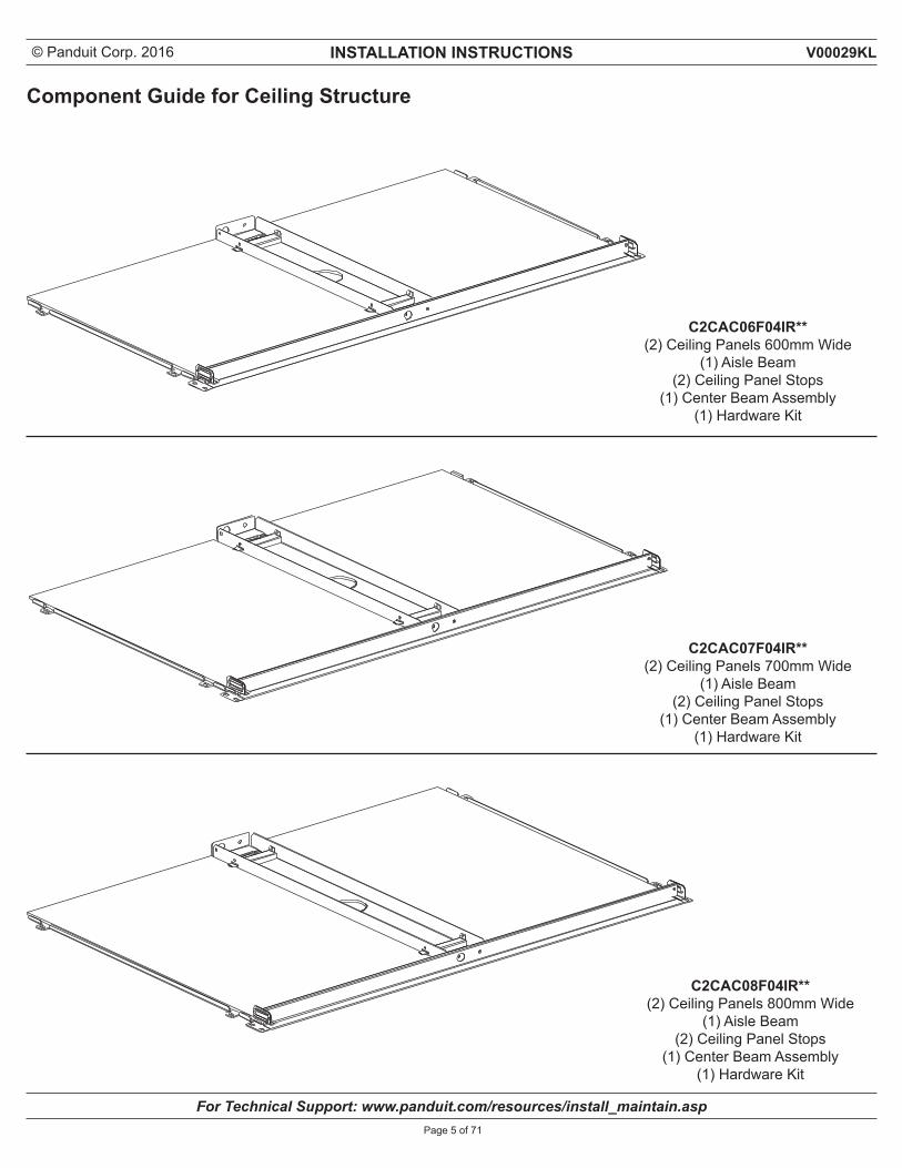
Component Guide for Ceiling Structure
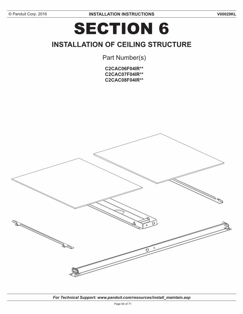
C2CAC06F04IR**(2) Ceiling Panels 600mm Wide
(1) Aisle Beam(2) Ceiling Panel Stops
(1) Center Beam Assembly(1) Hardware Kit
C2CAC07F04IR**(2) Ceiling Panels 700mm Wide
(1) Aisle Beam(2) Ceiling Panel Stops
(1) Center Beam Assembly(1) Hardware Kit
C2CAC08F04IR**(2) Ceiling Panels 800mm Wide
(1) Aisle Beam(2) Ceiling Panel Stops
(1) Center Beam Assembly(1) Hardware Kit
© Panduit Corp. 2016 INSTALLATION INSTRUCTIONS
For Technical Support: www.panduit.com/resources/install_maintain.asp
V00029KL
Page 6 of 71
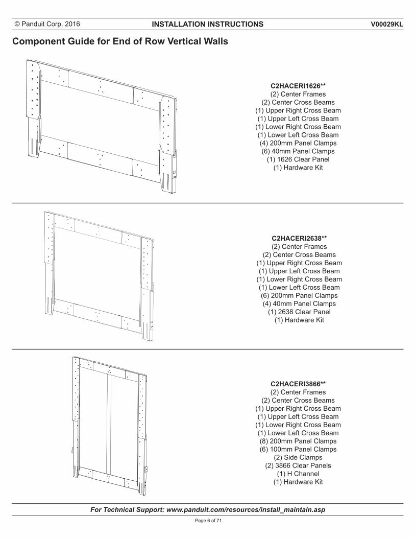
Component Guide for End of Row Vertical Walls
C2HACERI1626**(2) Center Frames
(2) Center Cross Beams(1) Upper Right Cross Beam(1) Upper Left Cross Beam
(1) Lower Right Cross Beam(1) Lower Left Cross Beam(4) 200mm Panel Clamps(6) 40mm Panel Clamps
(1) 1626 Clear Panel(1) Hardware Kit
C2HACERI2638**(2) Center Frames
(2) Center Cross Beams(1) Upper Right Cross Beam(1) Upper Left Cross Beam
(1) Lower Right Cross Beam(1) Lower Left Cross Beam(6) 200mm Panel Clamps(4) 40mm Panel Clamps
(1) 2638 Clear Panel(1) Hardware Kit
C2HACERI3866**(2) Center Frames
(2) Center Cross Beams(1) Upper Right Cross Beam(1) Upper Left Cross Beam
(1) Lower Right Cross Beam(1) Lower Left Cross Beam(8) 200mm Panel Clamps(6) 100mm Panel Clamps
(2) Side Clamps(2) 3866 Clear Panels
(1) H Channel(1) Hardware Kit
© Panduit Corp. 2016 INSTALLATION INSTRUCTIONS
For Technical Support: www.panduit.com/resources/install_maintain.asp
V00029KL
Page 7 of 71
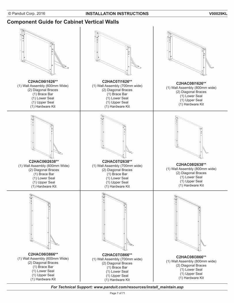
Component Guide for Cabinet Vertical Walls
C2HAC06I1626**(1) Wall Assembly (600mm Wide)
(2) Diagonal Braces(1) Brace Bar
(1) Lower Seal(1) Upper Seal
(1) Hardware Kit
C2HAC07I1626**(1) Wall Assembly (700mm wide)
(2) Diagonal Braces(1) Brace Bar
(1) Lower Seal(1) Upper Seal
(1) Hardware Kit
C2HAC08I1626**(1) Wall Assembly (800mm wide)
(2) Diagonal Braces(1) Lower Seal(1) Upper Seal
(1) Hardware Kit
C2HAC06I2638**(1) Wall Assembly (600mm Wide)
(2) Diagonal Braces(1) Brace Bar
(1) Lower Seal(1) Upper Seal
(1) Hardware Kit
C2HAC07I2638**(1) Wall Assembly (700mm wide)
(2) Diagonal Braces(1) Brace Bar
(1) Lower Seal(1) Upper Seal
(1) Hardware Kit
C2HAC08I2638**(1) Wall Assembly (800mm wide)
(2) Diagonal Braces(1) Lower Seal(1) Upper Seal
(1) Hardware Kit
C2HAC06I3866**(1) Wall Assembly (600mm Wide)
(2) Diagonal Braces(1) Brace Bar
(1) Lower Seal(1) Upper Seal
(1) Hardware Kit
C2HAC07I3866**(1) Wall Assembly (700mm wide)
(2) Diagonal Braces(1) Brace Bar
(1) Lower Seal(1) Upper Seal
(1) Hardware Kit
C2HAC08I3866**(1) Wall Assembly (800mm wide)
(2) Diagonal Braces(1) Lower Seal(1) Upper Seal
(1) Hardware Kit
© Panduit Corp. 2016 INSTALLATION INSTRUCTIONS
For Technical Support: www.panduit.com/resources/install_maintain.asp
V00029KL
Page 8 of 71
Table of Contents
SECTION 1 ........................................................................................................................................................10Floor Layouts for 4 Foot/ 1200mm Aisle Width Configurations Alignment of Cabinet on Raised Floor...................................................................................................................................... 11Leveling Cabinet..........................................................................................................................................................................12Aligning Rows of Cabinets.........................................................................................................................................................13Spacing of 4 Foot/ 1200mm Aisle Width for Vertical Wall Applications ...............................................................................14Spacing of 4 Foot/ 1200mm Aisle Width for Roofing application ..........................................................................................15Floor Layout for Installing Door Adapters ...............................................................................................................................16
SECTION 2 ........................................................................................................................................................17Installation of Cabinet Vertical WallAttaching Diagonal Brace to Wall Panel ...................................................................................................................................18Apply Foam Seal to Wall Panel ..................................................................................................................................................19Attaching Brace Bar to Cabinet (Only for 600mm and 700mm Wide Cabinets) ...................................................................20Attaching Wall Panel to Cabinet (For 600mm and 700mm Cabinets) ....................................................................................21Attaching Wall Panel to Cabinet (For 800mm Cabinets) .........................................................................................................22Setting Wall Panel Height ...........................................................................................................................................................23Aligning Rows of Cabinets.........................................................................................................................................................24Sizing Upper Seal ........................................................................................................................................................................25Attaching Upper Seal ..................................................................................................................................................................26Attaching Foam to Lower Seal...................................................................................................................................................27Attaching Lower Seal..................................................................................................................................................................28Ganging Cabinets .......................................................................................................................................................................29
SECTION 3 .......................................................................................................................................................30Installation of End of Row Vertical WallAttaching Lower Side Frame .....................................................................................................................................................31Attaching Lower Cross Beams ..................................................................................................................................................32Attaching Upper Cross Beams ..................................................................................................................................................33Attach Foam Seal to Upper Side Frame ....................................................................................................................................34Attaching Upper Side Frame ......................................................................................................................................................35Attach Center Cross Beams ......................................................................................................................................................36Attach Center Frames .................................................................................................................................................................37Assemble H Channel (For C2HACERI3866 Only).....................................................................................................................38Attach H Channel to Center Frame (For C2HACERI3866 Only) ..............................................................................................39Mark and Cut H Channel (For C2HACERI3866 Only) ...............................................................................................................40Measure and Cut Wall Panel ......................................................................................................................................................41Attaching H Channel to Clear Panels (For C2HACERI3866 Only) ..........................................................................................42Attach Bottom and Side Wall Panel Clamps ............................................................................................................................43Insert Wall Panel .........................................................................................................................................................................44Attach Top and Remaining Side Wall Panel Clamps ...............................................................................................................45Foam Seal Installation ................................................................................................................................................................46
© Panduit Corp. 2016 INSTALLATION INSTRUCTIONS
For Technical Support: www.panduit.com/resources/install_maintain.asp
V00029KL
Page 9 of 71
SECTION 4 ........................................................................................................................................................47Installation of Wall Panels (Installed on Roofing Version only)
Wall Panel Installation ................................................................................................................................................................48Attaching Seals to Wall Panels ..................................................................................................................................................49Wall Panel Seal Installation / Ganging and Securing Cabinets to Floor ...............................................................................50Wall Panel Covers to be Installed at end of next Section 6 ....................................................................................................51
SECTION 5 .......................................................................................................................................................52Installation of HAC/CAC Door Adapters and DoorsInserting Cage Nut into S-Type Cabinets .................................................................................................................................53Attaching Feet to the Floor ........................................................................................................................................................54Attaching Aisle Beam (for Roof Version only) .........................................................................................................................55Attaching Cabinet Brackets (Roof Version) .............................................................................................................................56Attaching Cabinet Brackets (Vertical Wall Version - No Aisle Beam) ...................................................................................57Attaching Foam Seal ...................................................................................................................................................................58Attach Transom on 42RU or 48RU ............................................................................................................................................59Attach Transom on 45RU or 51RU .............................................................................................................................................60Attach Door Rails ........................................................................................................................................................................62Install Dual Door onto the Door Adapter Frame ......................................................................................................................63
SECTION 6 .......................................................................................................................................................64Installation of Ceiling Structure Initial Aisle Beam Installation ....................................................................................................................................................65Aisle Beam Alignment ................................................................................................................................................................66Additional Aisle Beam Installation ............................................................................................................................................67Ceiling Panel Stop Installation ..................................................................................................................................................68Ceiling Support Bracket Installation .........................................................................................................................................69Ceiling Panel Installation ...........................................................................................................................................................70Attaching Wall Panel Cover (Wall Panel Covers from Section 4) ..........................................................................................71
© Panduit Corp. 2016 INSTALLATION INSTRUCTIONS
For Technical Support: www.panduit.com/resources/install_maintain.asp
V00029KL
Page 10 of 71
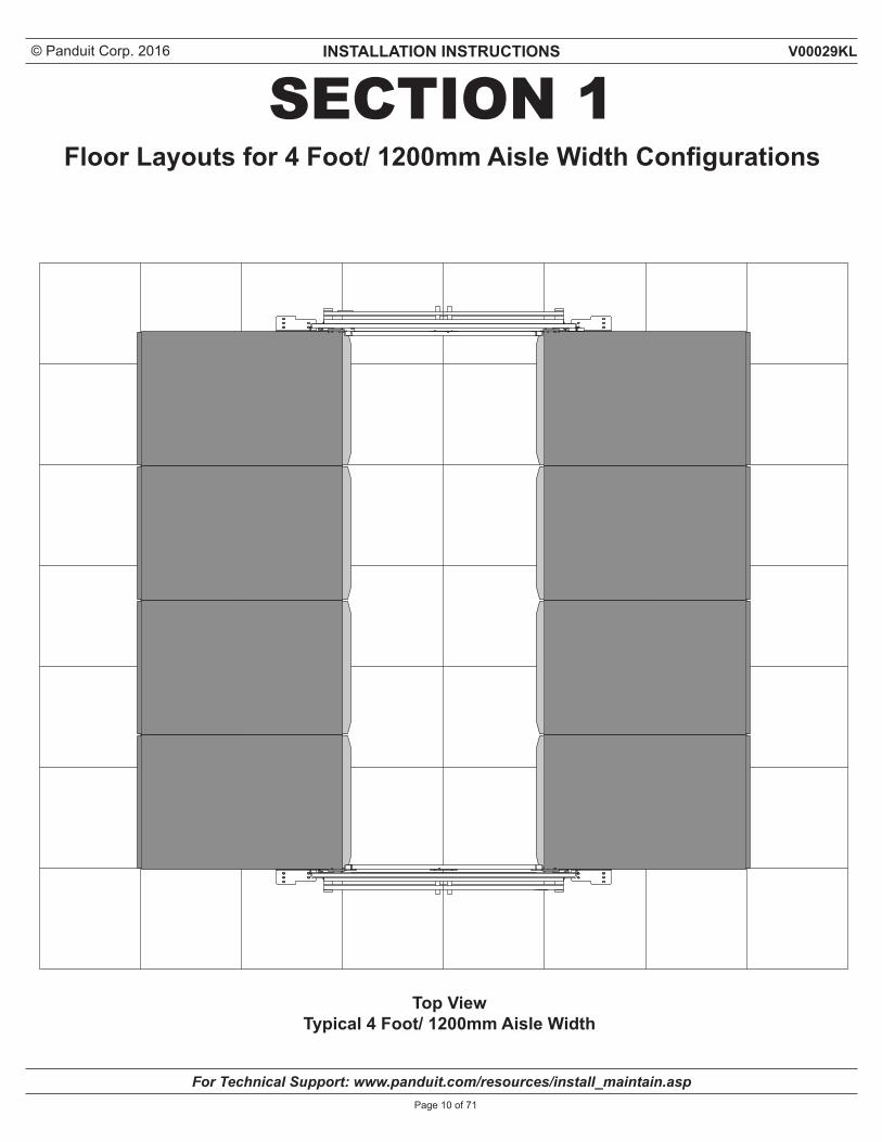
SECTION 1Floor Layouts for 4 Foot/ 1200mm Aisle Width Configurations
Top View Typical 4 Foot/ 1200mm Aisle Width
© Panduit Corp. 2016 INSTALLATION INSTRUCTIONS
For Technical Support: www.panduit.com/resources/install_maintain.asp
V00029KL
Page 11 of 71
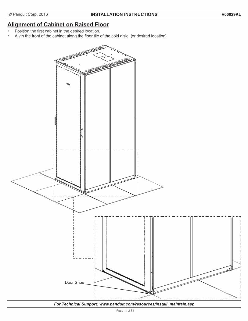
Alignment of Cabinet on Raised Floor• Position the first cabinet in the desired location.• Align the front of the cabinet along the floor tile of the cold aisle. (or desired location)
Door Shoe
© Panduit Corp. 2016 INSTALLATION INSTRUCTIONS
For Technical Support: www.panduit.com/resources/install_maintain.asp
V00029KL
Page 12 of 71
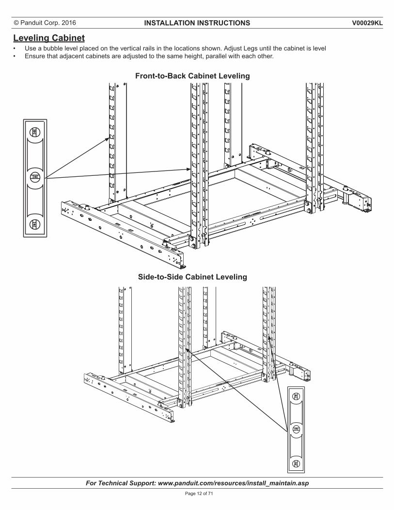
Leveling Cabinet• Use a bubble level placed on the vertical rails in the locations shown. Adjust Legs until the cabinet is level• Ensure that adjacent cabinets are adjusted to the same height, parallel with each other.
Front-to-Back Cabinet Leveling
Side-to-Side Cabinet Leveling
© Panduit Corp. 2016 INSTALLATION INSTRUCTIONS
For Technical Support: www.panduit.com/resources/install_maintain.asp
V00029KL
Page 13 of 71
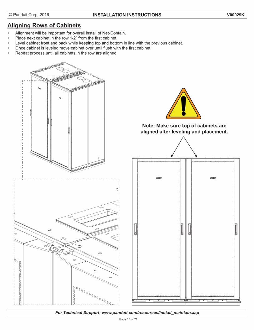
Aligning Rows of Cabinets• Alignment will be important for overall install of Net-Contain.• Place next cabinet in the row 1-2” from the first cabinet.• Level cabinet front and back while keeping top and bottom in line with the previous cabinet.• Once cabinet is leveled move cabinet over until flush with the first cabinet.• Repeat process until all cabinets in the row are aligned.
Note: Make sure top of cabinets are aligned after leveling and placement.
© Panduit Corp. 2016 INSTALLATION INSTRUCTIONS
For Technical Support: www.panduit.com/resources/install_maintain.asp
V00029KL
Page 14 of 71
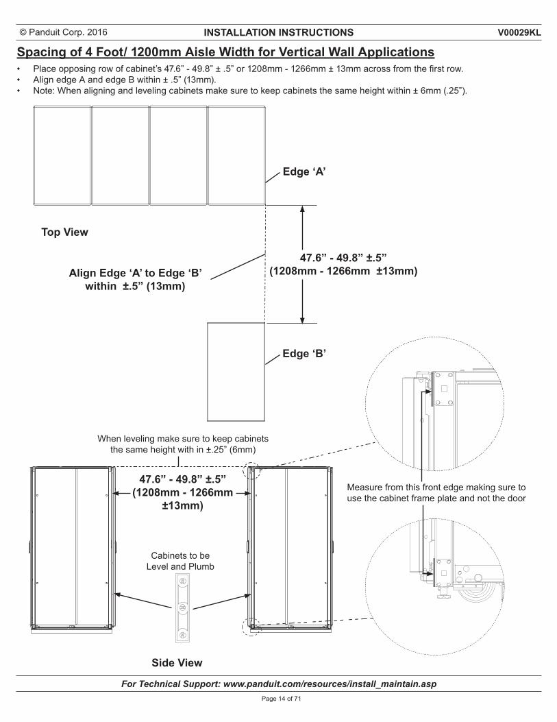
Spacing of 4 Foot/ 1200mm Aisle Width for Vertical Wall Applications• Place opposing row of cabinet’s 47.6” - 49.8” ± .5” or 1208mm - 1266mm ± 13mm across from the first row.• Align edge A and edge B within ± .5” (13mm).• Note: When aligning and leveling cabinets make sure to keep cabinets the same height within ± 6mm (.25”).
Align Edge ‘A’ to Edge ‘B’within ±.5” (13mm)
Top View
Side View
When leveling make sure to keep cabinets the same height with in ±.25” (6mm)
47.6” - 49.8” ±.5”(1208mm - 1266mm ±13mm)
Edge ‘A’
Edge ‘B’
47.6” - 49.8” ±.5”(1208mm - 1266mm
±13mm)
Cabinets to beLevel and Plumb
Measure from this front edge making sure to use the cabinet frame plate and not the door
© Panduit Corp. 2016 INSTALLATION INSTRUCTIONS
For Technical Support: www.panduit.com/resources/install_maintain.asp
V00029KL
Page 15 of 71
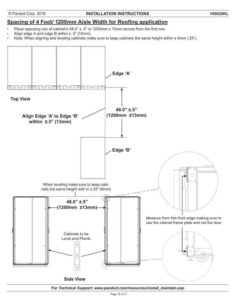
Spacing of 4 Foot/ 1200mm Aisle Width for Roofing application• Place opposing row of cabinet’s 48.0” ± .5” or 1200mm ± 13mm across from the first row.• Align edge A and edge B within ± .5” (13mm).• Note: When aligning and leveling cabinets make sure to keep cabinets the same height within ± 6mm (.25”).
Align Edge ‘A’ to Edge ‘B’within ±.5” (13mm)
Top View
Side View
When leveling make sure to keep cabi-nets the same height with in ±.25” (6mm)
48.0” ±.5”(1200mm ±13mm)
Edge ‘A’
Edge ‘B’
48.0” ±.5”(1200mm ±13mm)
Cabinets to beLevel and Plumb
Measure from this front edge making sure to use the cabinet frame plate and not the door
© Panduit Corp. 2016 INSTALLATION INSTRUCTIONS
For Technical Support: www.panduit.com/resources/install_maintain.asp
V00029KL
Page 16 of 71
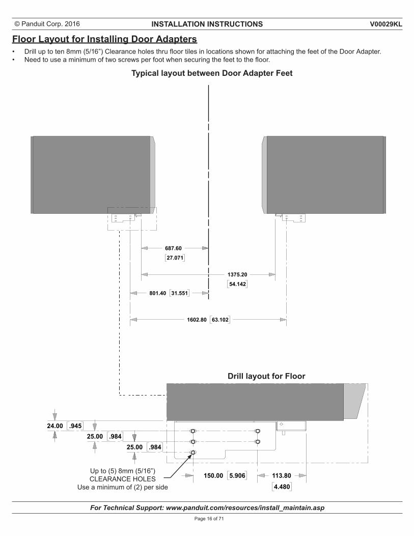
Up to (5) 8mm (5/16”) CLEARANCE HOLES
Use a minimum of (2) per side
Floor Layout for Installing Door Adapters• Drill up to ten 8mm (5/16”) Clearance holes thru floor tiles in locations shown for attaching the feet of the Door Adapter.• Need to use a minimum of two screws per foot when securing the feet to the floor.
Typical layout between Door Adapter Feet
Drill layout for Floor
© Panduit Corp. 2016 INSTALLATION INSTRUCTIONS
For Technical Support: www.panduit.com/resources/install_maintain.asp
V00029KL
Page 17 of 71
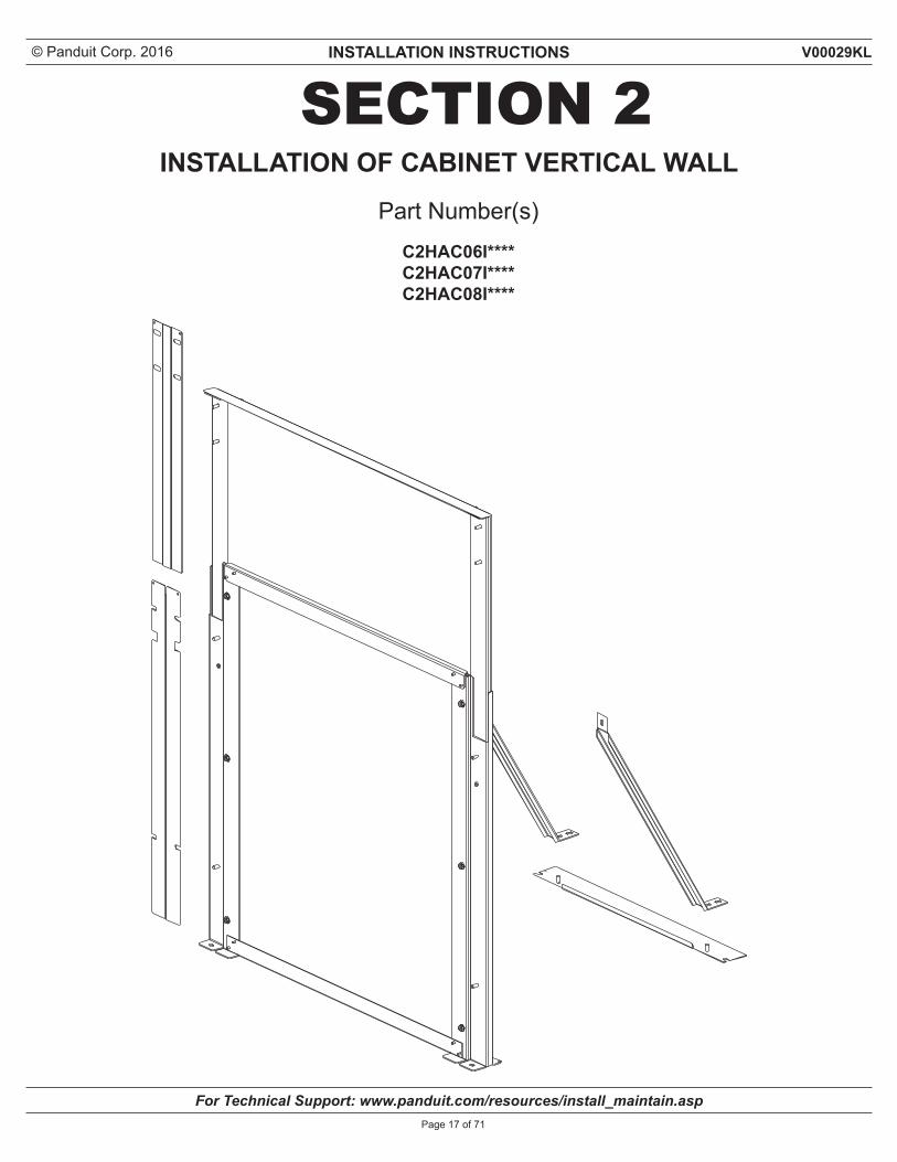
SECTION 2Part Number(s)
C2HAC06I**** C2HAC07I****C2HAC08I****
INSTALLATION OF CABINET VERTICAL WALL
© Panduit Corp. 2016 INSTALLATION INSTRUCTIONS
For Technical Support: www.panduit.com/resources/install_maintain.asp
V00029KL
Page 18 of 71
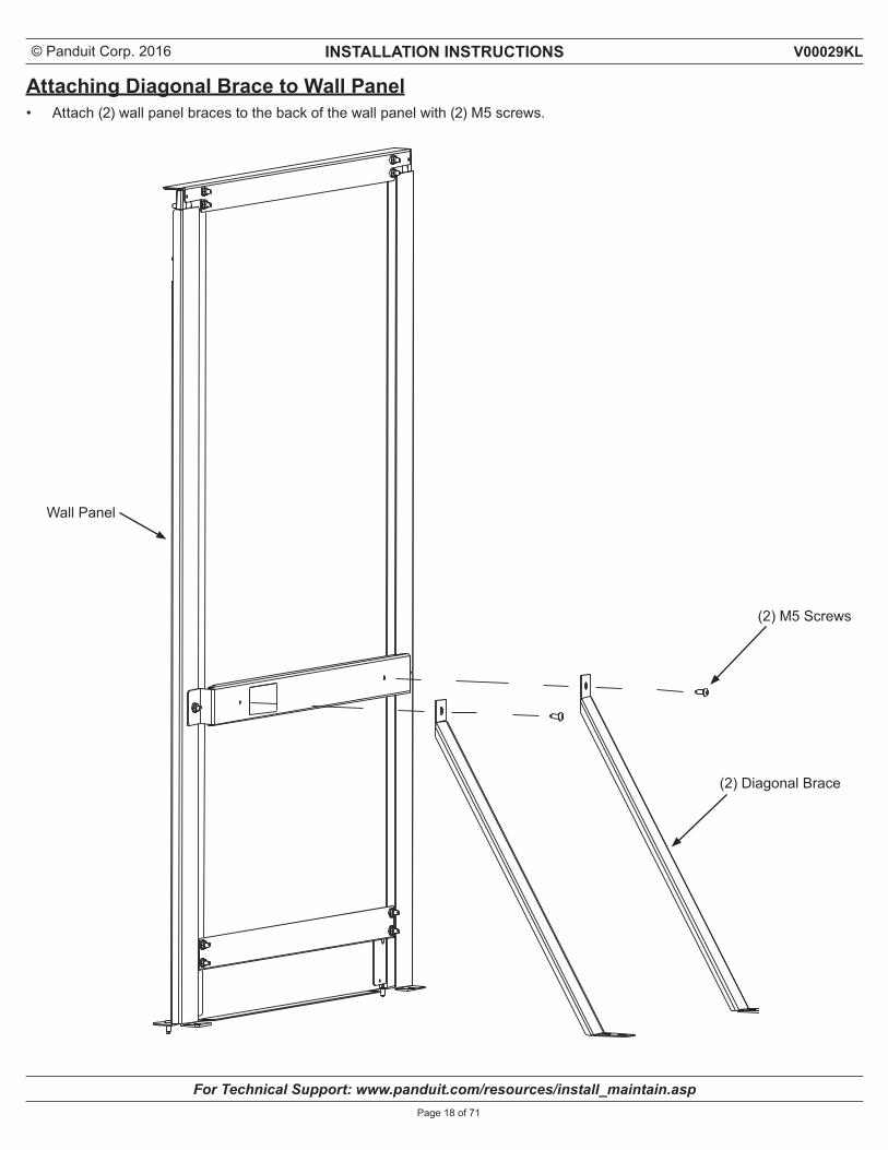
Attaching Diagonal Brace to Wall Panel• Attach (2) wall panel braces to the back of the wall panel with (2) M5 screws.
(2) M5 Screws
Wall Panel
(2) Diagonal Brace
© Panduit Corp. 2016 INSTALLATION INSTRUCTIONS
For Technical Support: www.panduit.com/resources/install_maintain.asp
V00029KL
Page 19 of 71
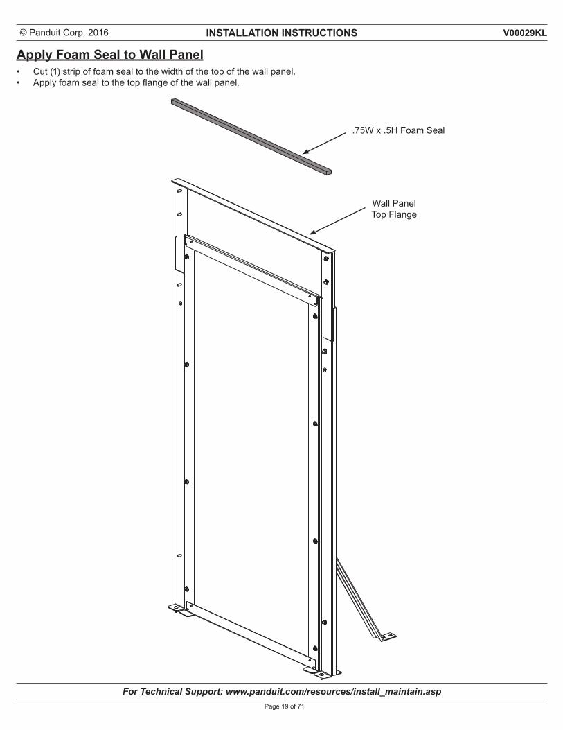
Apply Foam Seal to Wall Panel• Cut (1) strip of foam seal to the width of the top of the wall panel.• Apply foam seal to the top flange of the wall panel.
.75W x .5H Foam Seal
Wall Panel Top Flange
© Panduit Corp. 2016 INSTALLATION INSTRUCTIONS
For Technical Support: www.panduit.com/resources/install_maintain.asp
V00029KL
Page 20 of 71
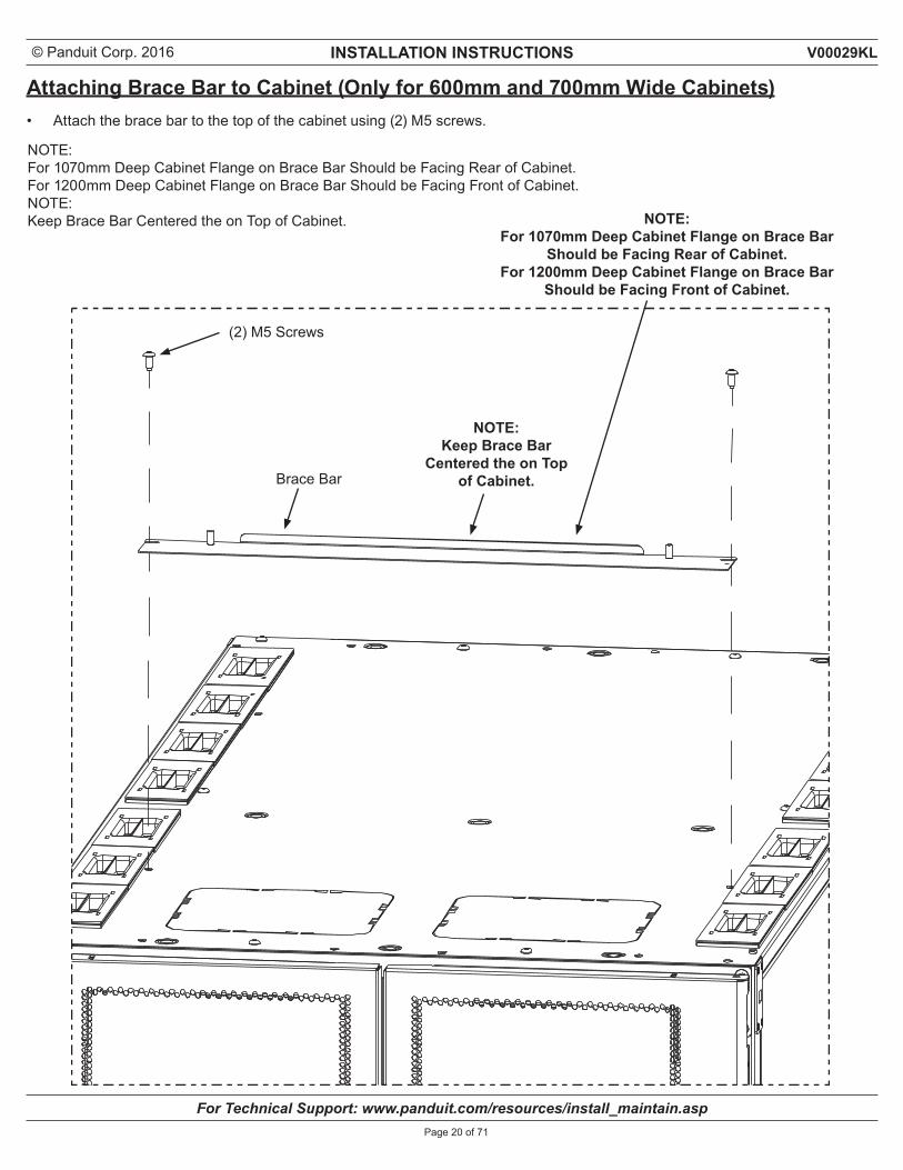
Attaching Brace Bar to Cabinet (Only for 600mm and 700mm Wide Cabinets)• Attach the brace bar to the top of the cabinet using (2) M5 screws.
(2) M5 Screws
NOTE: Keep Brace Bar
Centered the on Top of Cabinet.
NOTE: For 1070mm Deep Cabinet Flange on Brace Bar
Should be Facing Rear of Cabinet.For 1200mm Deep Cabinet Flange on Brace Bar
Should be Facing Front of Cabinet.
Brace Bar
NOTE: For 1070mm Deep Cabinet Flange on Brace Bar Should be Facing Rear of Cabinet.For 1200mm Deep Cabinet Flange on Brace Bar Should be Facing Front of Cabinet.NOTE: Keep Brace Bar Centered the on Top of Cabinet.
© Panduit Corp. 2016 INSTALLATION INSTRUCTIONS
For Technical Support: www.panduit.com/resources/install_maintain.asp
V00029KL
Page 21 of 71
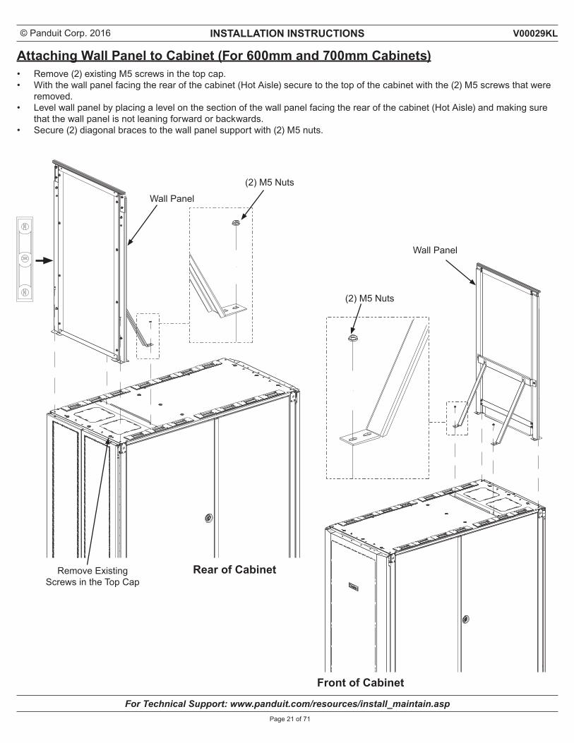
Attaching Wall Panel to Cabinet (For 600mm and 700mm Cabinets)• Remove (2) existing M5 screws in the top cap.• With the wall panel facing the rear of the cabinet (Hot Aisle) secure to the top of the cabinet with the (2) M5 screws that were
removed.• Level wall panel by placing a level on the section of the wall panel facing the rear of the cabinet (Hot Aisle) and making sure
that the wall panel is not leaning forward or backwards.• Secure (2) diagonal braces to the wall panel support with (2) M5 nuts.
Wall Panel
(2) M5 Nuts
Wall Panel
Remove Existing Screws in the Top Cap
(2) M5 Nuts
Rear of Cabinet
Front of Cabinet
© Panduit Corp. 2016 INSTALLATION INSTRUCTIONS
For Technical Support: www.panduit.com/resources/install_maintain.asp
V00029KL
Page 22 of 71
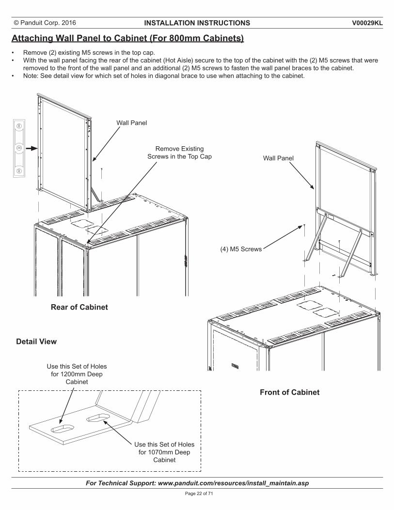
Attaching Wall Panel to Cabinet (For 800mm Cabinets)• Remove (2) existing M5 screws in the top cap.• With the wall panel facing the rear of the cabinet (Hot Aisle) secure to the top of the cabinet with the (2) M5 screws that were
removed to the front of the wall panel and an additional (2) M5 screws to fasten the wall panel braces to the cabinet.• Note: See detail view for which set of holes in diagonal brace to use when attaching to the cabinet.
Wall Panel
Remove Existing Screws in the Top Cap Wall Panel
(4) M5 Screws
Detail View
Use this Set of Holes for 1200mm Deep
Cabinet
Use this Set of Holes for 1070mm Deep
Cabinet
Rear of Cabinet
Front of Cabinet
© Panduit Corp. 2016 INSTALLATION INSTRUCTIONS
For Technical Support: www.panduit.com/resources/install_maintain.asp
V00029KL
Page 23 of 71
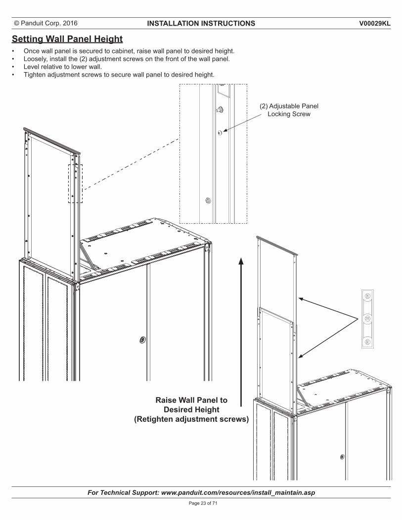
Setting Wall Panel Height• Once wall panel is secured to cabinet, raise wall panel to desired height. • Loosely, install the (2) adjustment screws on the front of the wall panel.• Level relative to lower wall.• Tighten adjustment screws to secure wall panel to desired height.
(2) Adjustable Panel Locking Screw
Raise Wall Panel toDesired Height
(Retighten adjustment screws)
© Panduit Corp. 2016 INSTALLATION INSTRUCTIONS
For Technical Support: www.panduit.com/resources/install_maintain.asp
V00029KL
Page 24 of 71
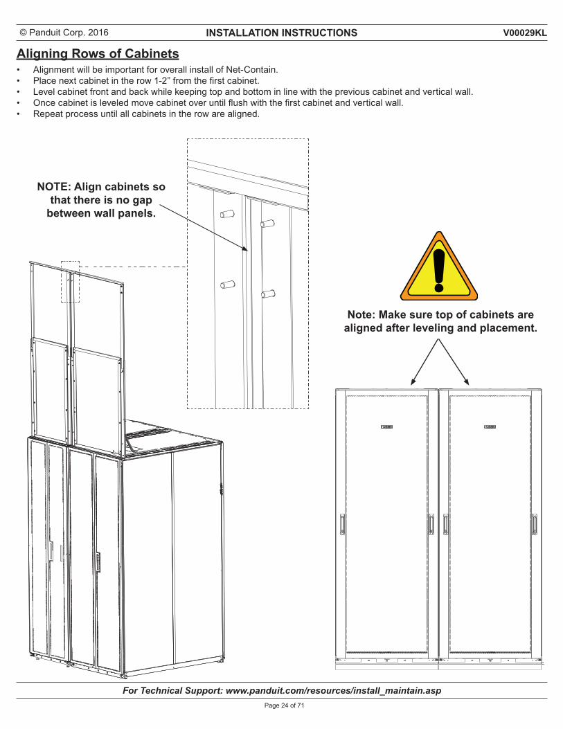
Aligning Rows of Cabinets• Alignment will be important for overall install of Net-Contain.• Place next cabinet in the row 1-2” from the first cabinet.• Level cabinet front and back while keeping top and bottom in line with the previous cabinet and vertical wall.• Once cabinet is leveled move cabinet over until flush with the first cabinet and vertical wall. • Repeat process until all cabinets in the row are aligned.
Note: Make sure top of cabinets are aligned after leveling and placement.
NOTE: Align cabinets sothat there is no gap
between wall panels.
© Panduit Corp. 2016 INSTALLATION INSTRUCTIONS
For Technical Support: www.panduit.com/resources/install_maintain.asp
V00029KL
Page 25 of 71
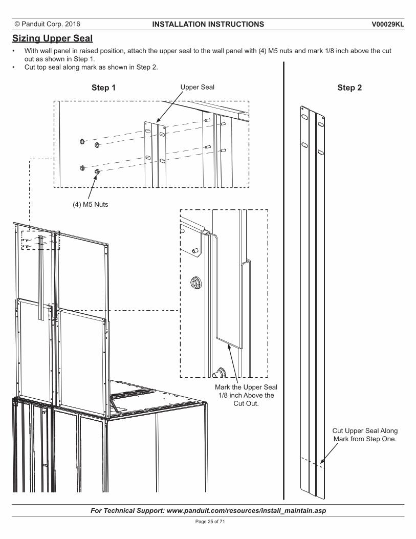
Sizing Upper Seal• With wall panel in raised position, attach the upper seal to the wall panel with (4) M5 nuts and mark 1/8 inch above the cut
out as shown in Step 1.• Cut top seal along mark as shown in Step 2.
(4) M5 Nuts
Step 1 Step 2Upper Seal
Mark the Upper Seal 1/8 inch Above the
Cut Out.
Cut Upper Seal Along Mark from Step One.
© Panduit Corp. 2016 INSTALLATION INSTRUCTIONS
For Technical Support: www.panduit.com/resources/install_maintain.asp
V00029KL
Page 26 of 71
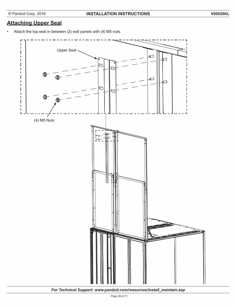
Attaching Upper Seal• Attach the top seal in between (2) wall panels with (4) M5 nuts.
(4) M5 Nuts
Upper Seal
© Panduit Corp. 2016 INSTALLATION INSTRUCTIONS
For Technical Support: www.panduit.com/resources/install_maintain.asp
V00029KL
Page 27 of 71
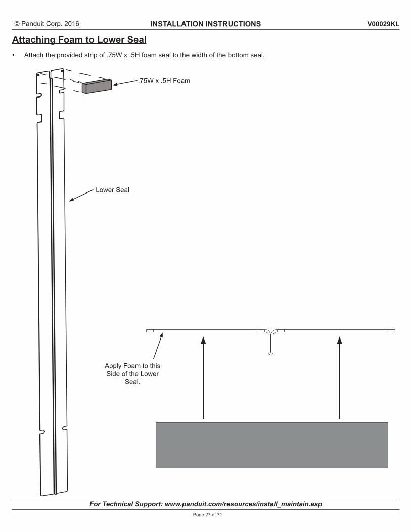
Attaching Foam to Lower Seal• Attach the provided strip of .75W x .5H foam seal to the width of the bottom seal.
Lower Seal
.75W x .5H Foam
Apply Foam to this Side of the Lower
Seal.
© Panduit Corp. 2016 INSTALLATION INSTRUCTIONS
For Technical Support: www.panduit.com/resources/install_maintain.asp
V00029KL
Page 28 of 71
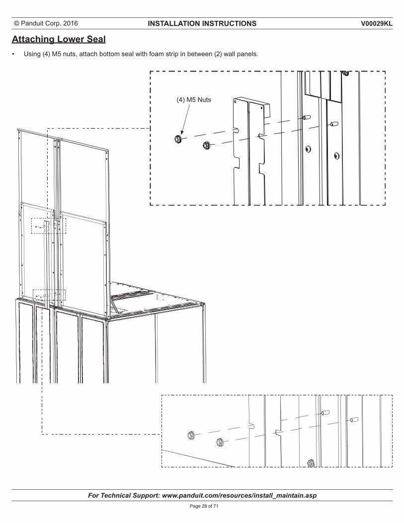
Attaching Lower Seal• Using (4) M5 nuts, attach bottom seal with foam strip in between (2) wall panels.
(4) M5 Nuts
© Panduit Corp. 2016 INSTALLATION INSTRUCTIONS
For Technical Support: www.panduit.com/resources/install_maintain.asp
V00029KL
Page 29 of 71
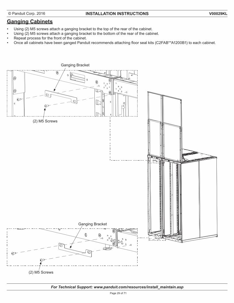
Ganging Cabinets• Using (2) M5 screws attach a ganging bracket to the top of the rear of the cabinet.• Using (2) M5 screws attach a ganging bracket to the bottom of the rear of the cabinet.• Repeat process for the front of the cabinet.• Once all cabinets have been ganged Panduit recommends attaching floor seal kits (C2FAB**A1200B1) to each cabinet.
(2) M5 Screws
(2) M5 Screws
Ganging Bracket
Ganging Bracket
© Panduit Corp. 2016 INSTALLATION INSTRUCTIONS
For Technical Support: www.panduit.com/resources/install_maintain.asp
V00029KL
Page 30 of 71
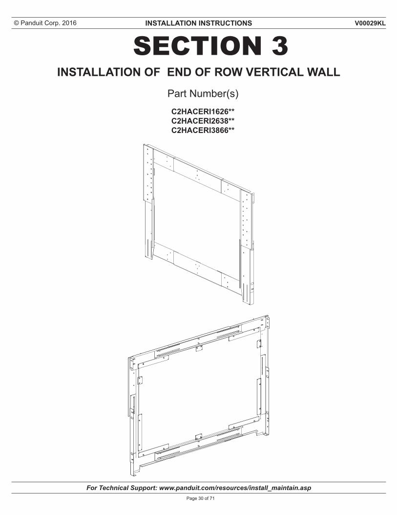
SECTION 3Part Number(s)C2HACERI1626**C2HACERI2638**C2HACERI3866**
INSTALLATION OF END OF ROW VERTICAL WALL
© Panduit Corp. 2016 INSTALLATION INSTRUCTIONS
For Technical Support: www.panduit.com/resources/install_maintain.asp
V00029KL
Page 31 of 71
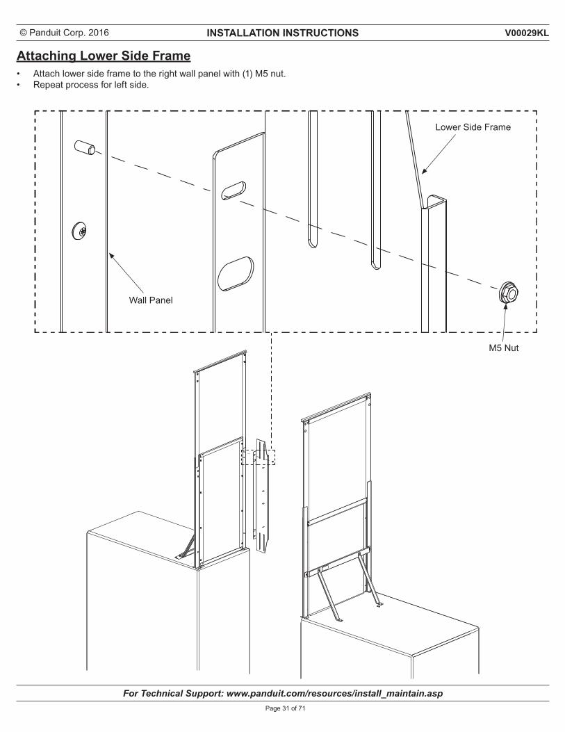
Attaching Lower Side Frame• Attach lower side frame to the right wall panel with (1) M5 nut.• Repeat process for left side.
Lower Side Frame
M5 Nut
Wall Panel
© Panduit Corp. 2016 INSTALLATION INSTRUCTIONS
For Technical Support: www.panduit.com/resources/install_maintain.asp
V00029KL
Page 32 of 71
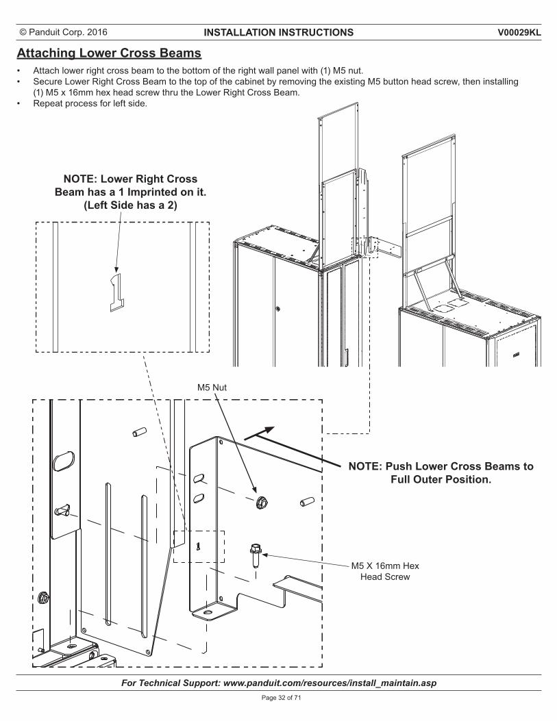
Attaching Lower Cross Beams• Attach lower right cross beam to the bottom of the right wall panel with (1) M5 nut.• Secure Lower Right Cross Beam to the top of the cabinet by removing the existing M5 button head screw, then installing
(1) M5 x 16mm hex head screw thru the Lower Right Cross Beam.• Repeat process for left side.
NOTE: Lower Right Cross Beam has a 1 Imprinted on it.
(Left Side has a 2)
NOTE: Push Lower Cross Beams to Full Outer Position.
M5 Nut
M5 X 16mm Hex Head Screw
© Panduit Corp. 2016 INSTALLATION INSTRUCTIONS
For Technical Support: www.panduit.com/resources/install_maintain.asp
V00029KL
Page 33 of 71
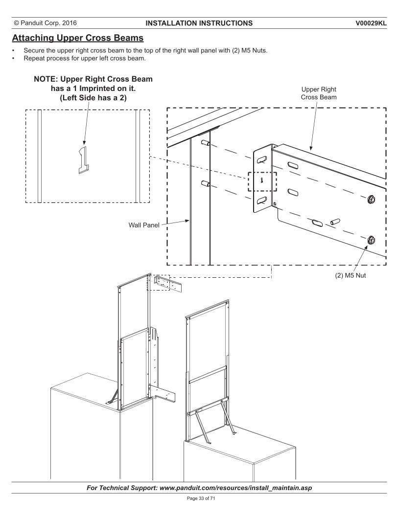
Attaching Upper Cross Beams• Secure the upper right cross beam to the top of the right wall panel with (2) M5 Nuts.• Repeat process for upper left cross beam.
(2) M5 Nut
NOTE: Upper Right Cross Beam has a 1 Imprinted on it.
(Left Side has a 2)
Wall Panel
Upper RightCross Beam
© Panduit Corp. 2016 INSTALLATION INSTRUCTIONS
For Technical Support: www.panduit.com/resources/install_maintain.asp
V00029KL
Page 34 of 71
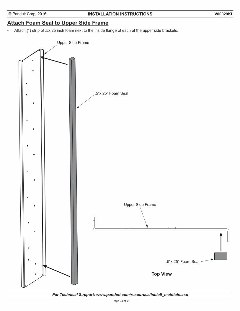
Attach Foam Seal to Upper Side Frame• Attach (1) strip of .5x.25 inch foam next to the inside flange of each of the upper side brackets.
Top View
Upper Side Frame
.5”x.25” Foam Seal
Upper Side Frame
.5”x.25” Foam Seal
© Panduit Corp. 2016 INSTALLATION INSTRUCTIONS
For Technical Support: www.panduit.com/resources/install_maintain.asp
V00029KL
Page 35 of 71
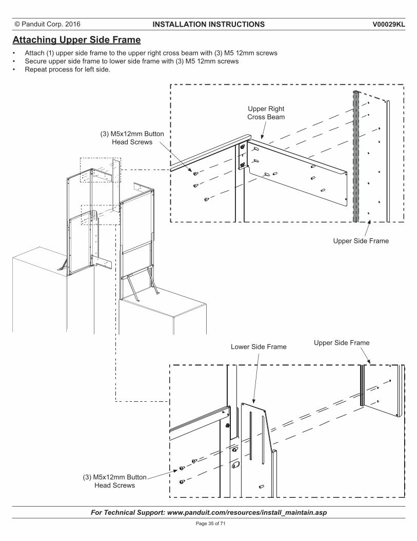
Attaching Upper Side Frame• Attach (1) upper side frame to the upper right cross beam with (3) M5 12mm screws• Secure upper side frame to lower side frame with (3) M5 12mm screws• Repeat process for left side.
Upper RightCross Beam
(3) M5x12mm Button Head Screws
Lower Side Frame Upper Side Frame
Upper Side Frame
(3) M5x12mm Button Head Screws
© Panduit Corp. 2016 INSTALLATION INSTRUCTIONS
For Technical Support: www.panduit.com/resources/install_maintain.asp
V00029KL
Page 36 of 71
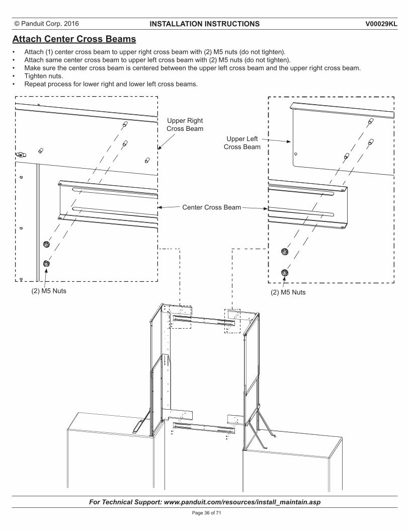
Attach Center Cross Beams• Attach (1) center cross beam to upper right cross beam with (2) M5 nuts (do not tighten).• Attach same center cross beam to upper left cross beam with (2) M5 nuts (do not tighten). • Make sure the center cross beam is centered between the upper left cross beam and the upper right cross beam.• Tighten nuts.• Repeat process for lower right and lower left cross beams.
Upper Right Cross Beam
(2) M5 Nuts(2) M5 Nuts
Center Cross Beam
Upper LeftCross Beam
© Panduit Corp. 2016 INSTALLATION INSTRUCTIONS
For Technical Support: www.panduit.com/resources/install_maintain.asp
V00029KL
Page 37 of 71
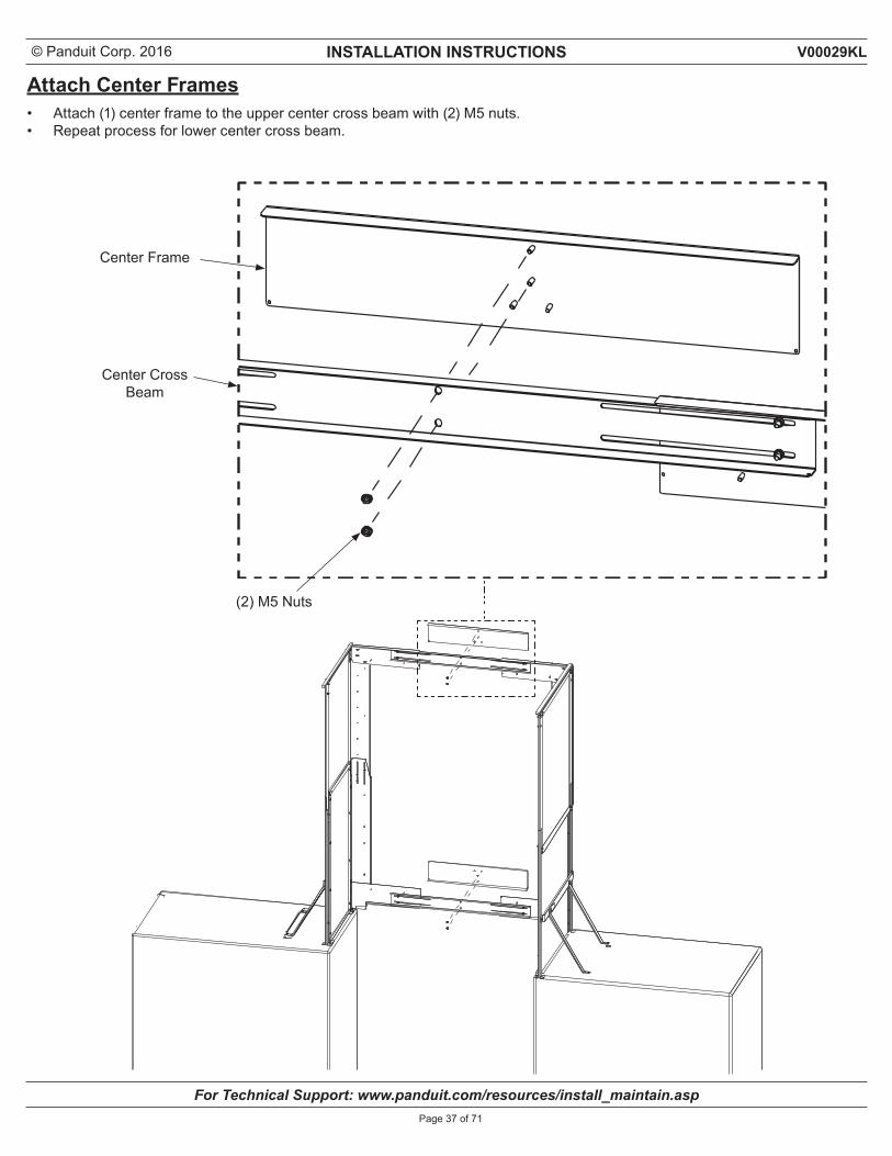
Attach Center Frames• Attach (1) center frame to the upper center cross beam with (2) M5 nuts.• Repeat process for lower center cross beam.
(2) M5 Nuts
Center CrossBeam
Center Frame
© Panduit Corp. 2016 INSTALLATION INSTRUCTIONS
For Technical Support: www.panduit.com/resources/install_maintain.asp
V00029KL
Page 38 of 71
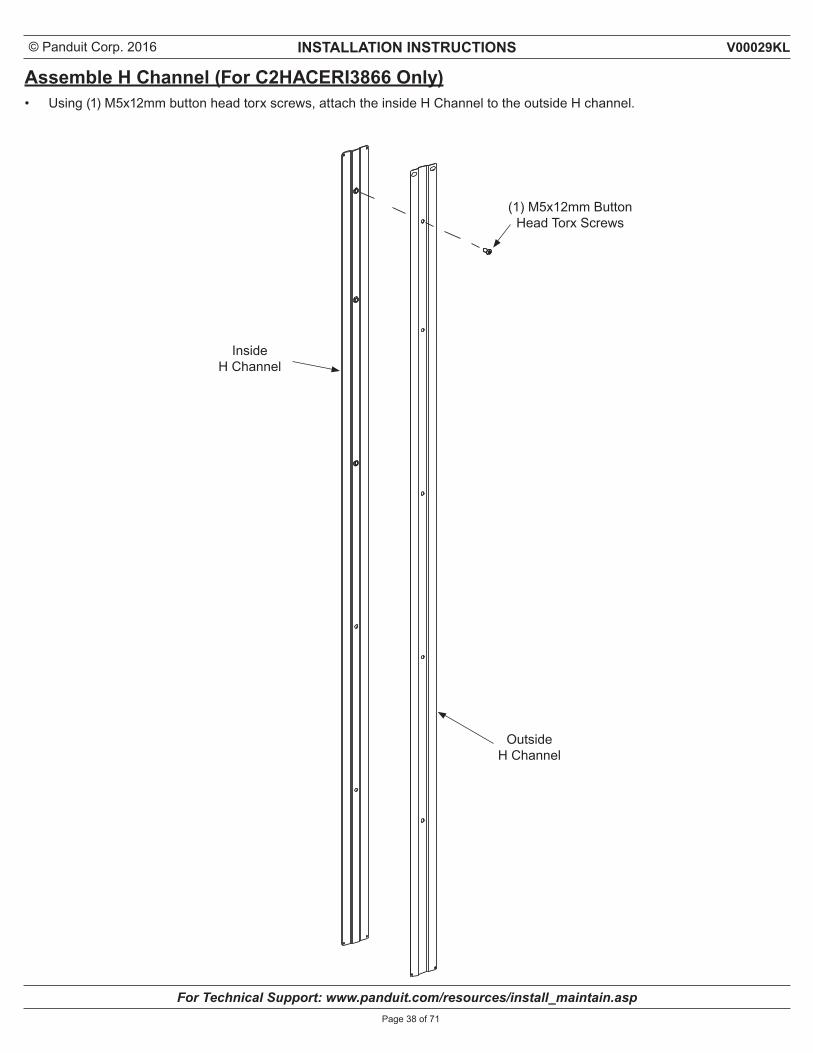
Assemble H Channel (For C2HACERI3866 Only)• Using (1) M5x12mm button head torx screws, attach the inside H Channel to the outside H channel.
Inside H Channel
Outside H Channel
(1) M5x12mm Button Head Torx Screws
© Panduit Corp. 2016 INSTALLATION INSTRUCTIONS
For Technical Support: www.panduit.com/resources/install_maintain.asp
V00029KL
Page 39 of 71
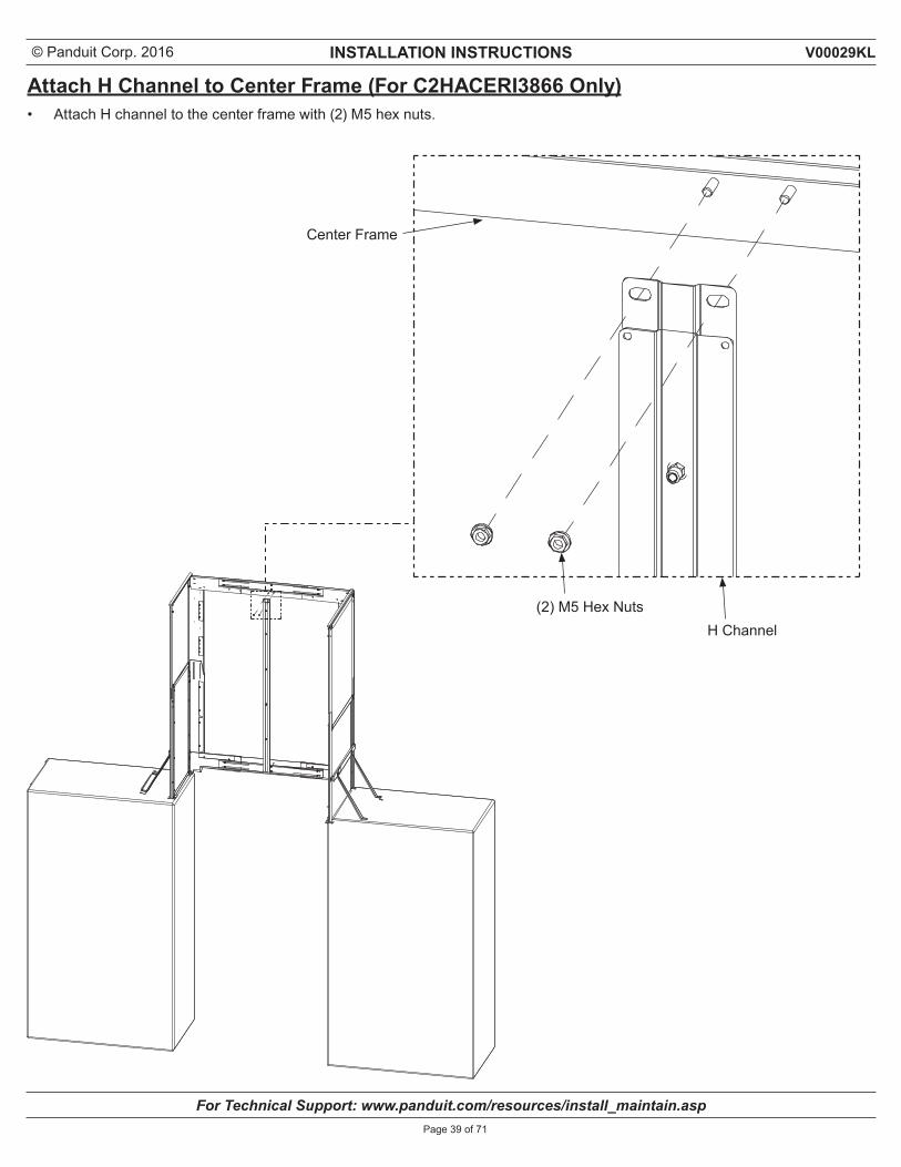
Attach H Channel to Center Frame (For C2HACERI3866 Only)• Attach H channel to the center frame with (2) M5 hex nuts.
Center Frame
(2) M5 Hex NutsH Channel
© Panduit Corp. 2016 INSTALLATION INSTRUCTIONS
For Technical Support: www.panduit.com/resources/install_maintain.asp
V00029KL
Page 40 of 71
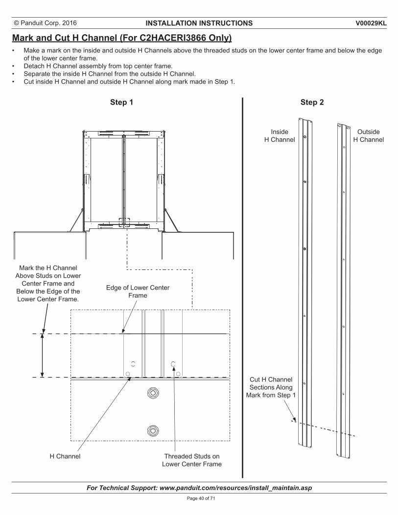
Mark and Cut H Channel (For C2HACERI3866 Only)• Make a mark on the inside and outside H Channels above the threaded studs on the lower center frame and below the edge
of the lower center frame.• Detach H Channel assembly from top center frame.• Separate the inside H Channel from the outside H Channel.• Cut inside H Channel and outside H Channel along mark made in Step 1.
Edge of Lower Center Frame
Step 1 Step 2
H Channel Threaded Studs on Lower Center Frame
Mark the H Channel Above Studs on Lower
Center Frame and Below the Edge of the Lower Center Frame.
InsideH Channel
Cut H ChannelSections Along
Mark from Step 1
OutsideH Channel
© Panduit Corp. 2016 INSTALLATION INSTRUCTIONS
For Technical Support: www.panduit.com/resources/install_maintain.asp
V00029KL
Page 41 of 71
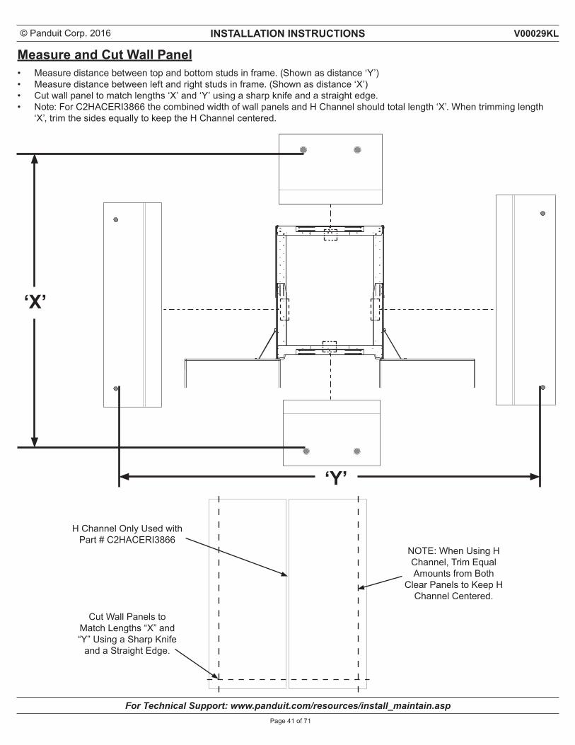
Measure and Cut Wall Panel• Measure distance between top and bottom studs in frame. (Shown as distance ‘Y’)• Measure distance between left and right studs in frame. (Shown as distance ‘X’)• Cut wall panel to match lengths ‘X’ and ‘Y’ using a sharp knife and a straight edge.• Note: For C2HACERI3866 the combined width of wall panels and H Channel should total length ‘X’. When trimming length
‘X’, trim the sides equally to keep the H Channel centered.
‘X’
Cut Wall Panels to Match Lengths “X” and “Y” Using a Sharp Knife
and a Straight Edge.
‘Y’
NOTE: When Using H Channel, Trim Equal Amounts from Both
Clear Panels to Keep H Channel Centered.
H Channel Only Used with Part # C2HACERI3866
© Panduit Corp. 2016 INSTALLATION INSTRUCTIONS
For Technical Support: www.panduit.com/resources/install_maintain.asp
V00029KL
Page 42 of 71
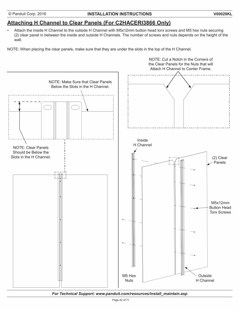
Attaching H Channel to Clear Panels (For C2HACERI3866 Only)• Attach the inside H Channel to the outside H Channel with M5x12mm button head torx screws and M5 hex nuts securing
(2) clear panel in between the inside and outside H Channels. The number of screws and nuts depends on the height of the wall.
NOTE: When placing the clear panels, make sure that they are under the slots in the top of the H Channel.
NOTE: Make Sure that Clear PanelsBelow the Slots in the H Channel.
NOTE: Clear Panels Should be Below the
Slots in the H Channel.
NOTE: Cut a Notch in the Corners of the Clear Panels for the Nuts that will Attach H Channel to Center Frame.
Inside H Channel
M5x12mm Button Head Torx Screws
Outside H Channel
M5 Hex Nuts
(2) Clear Panels
© Panduit Corp. 2016 INSTALLATION INSTRUCTIONS
For Technical Support: www.panduit.com/resources/install_maintain.asp
V00029KL
Page 43 of 71
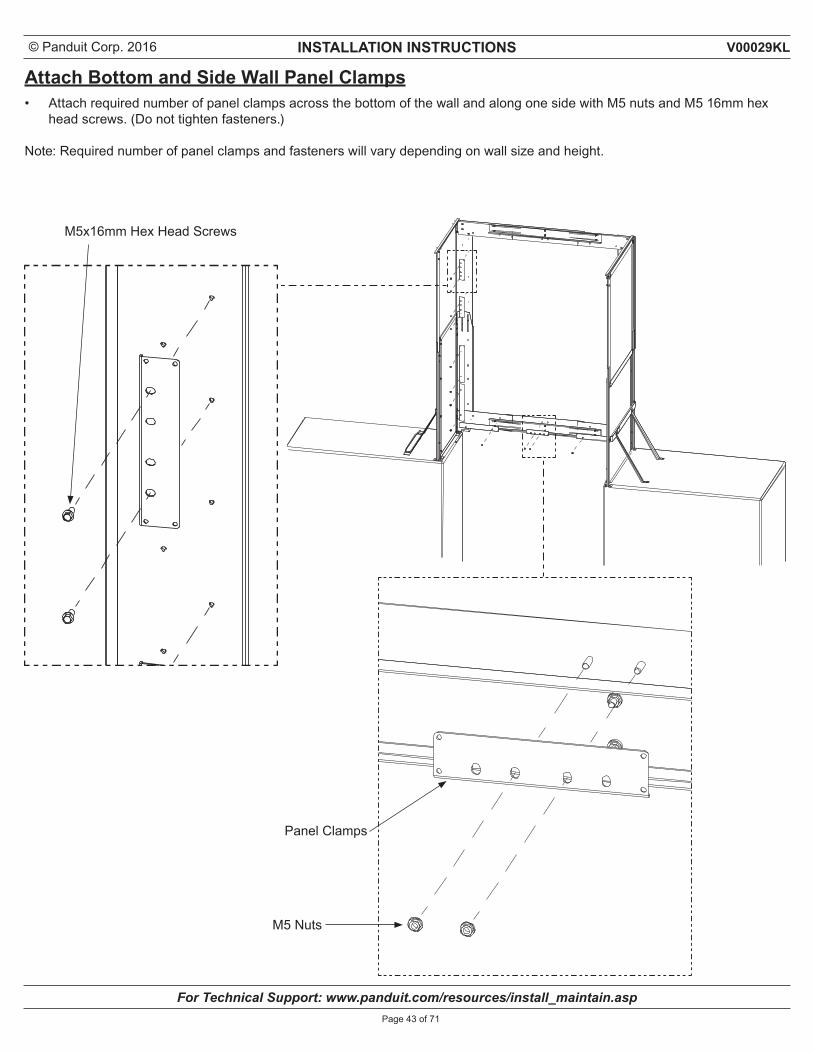
Attach Bottom and Side Wall Panel Clamps• Attach required number of panel clamps across the bottom of the wall and along one side with M5 nuts and M5 16mm hex
head screws. (Do not tighten fasteners.)
Note: Required number of panel clamps and fasteners will vary depending on wall size and height.
M5x16mm Hex Head Screws
Panel Clamps
M5 Nuts
© Panduit Corp. 2016 INSTALLATION INSTRUCTIONS
For Technical Support: www.panduit.com/resources/install_maintain.asp
V00029KL
Page 44 of 71
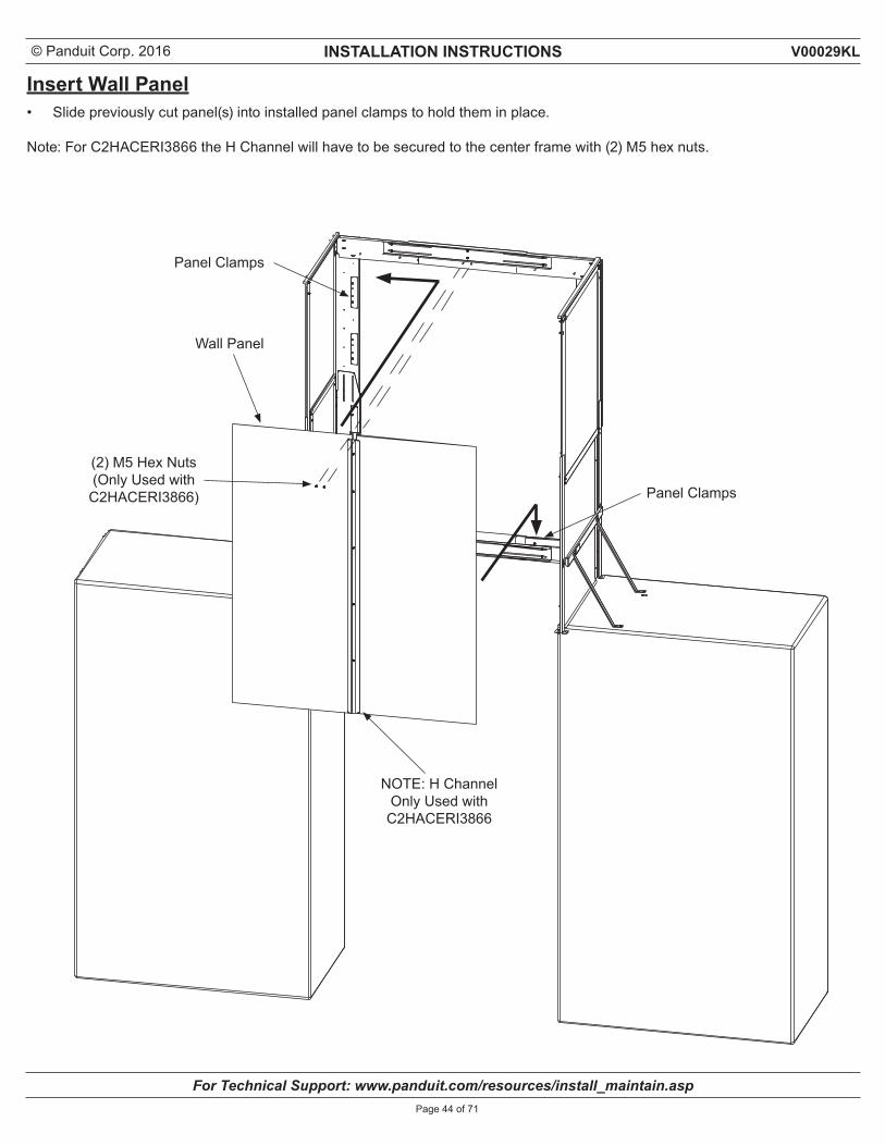
Insert Wall Panel• Slide previously cut panel(s) into installed panel clamps to hold them in place.
Note: For C2HACERI3866 the H Channel will have to be secured to the center frame with (2) M5 hex nuts.
Wall Panel
(2) M5 Hex Nuts(Only Used with
C2HACERI3866)
Panel Clamps
Panel Clamps
NOTE: H Channel Only Used with
C2HACERI3866
© Panduit Corp. 2016 INSTALLATION INSTRUCTIONS
For Technical Support: www.panduit.com/resources/install_maintain.asp
V00029KL
Page 45 of 71
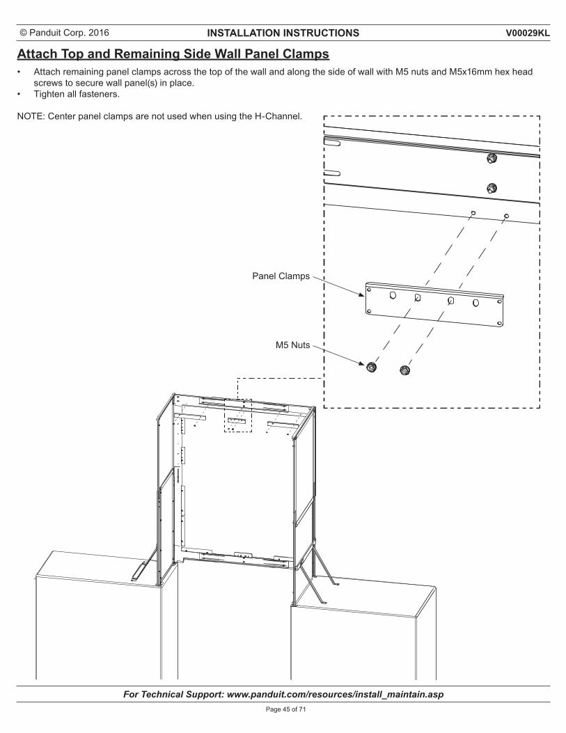
Attach Top and Remaining Side Wall Panel Clamps• Attach remaining panel clamps across the top of the wall and along the side of wall with M5 nuts and M5x16mm hex head
screws to secure wall panel(s) in place.• Tighten all fasteners.
NOTE: Center panel clamps are not used when using the H-Channel.
Panel Clamps
M5 Nuts
© Panduit Corp. 2016 INSTALLATION INSTRUCTIONS
For Technical Support: www.panduit.com/resources/install_maintain.asp
V00029KL
Page 46 of 71
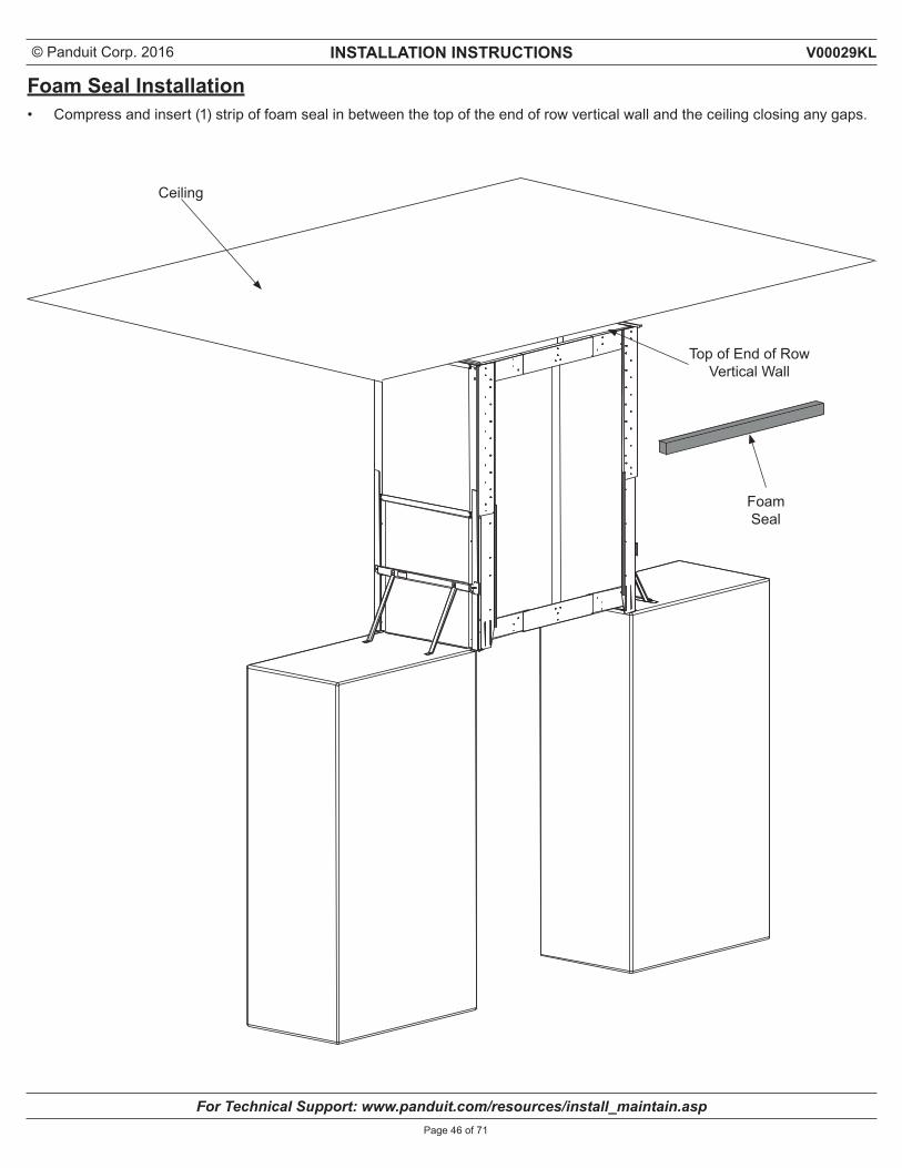
Foam Seal Installation• Compress and insert (1) strip of foam seal in between the top of the end of row vertical wall and the ceiling closing any gaps.
Ceiling
Top of End of Row Vertical Wall
FoamSeal
© Panduit Corp. 2016 INSTALLATION INSTRUCTIONS
For Technical Support: www.panduit.com/resources/install_maintain.asp
V00029KL
Page 47 of 71
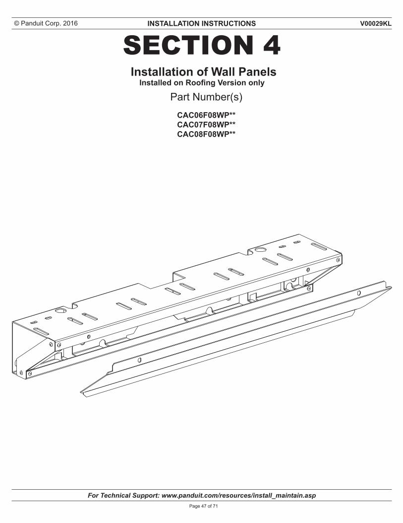
SECTION 4
Part Number(s)CAC06F08WP** CAC07F08WP** CAC08F08WP**
Installation of Wall PanelsInstalled on Roofing Version only
© Panduit Corp. 2016 INSTALLATION INSTRUCTIONS
For Technical Support: www.panduit.com/resources/install_maintain.asp
V00029KL
Page 48 of 71
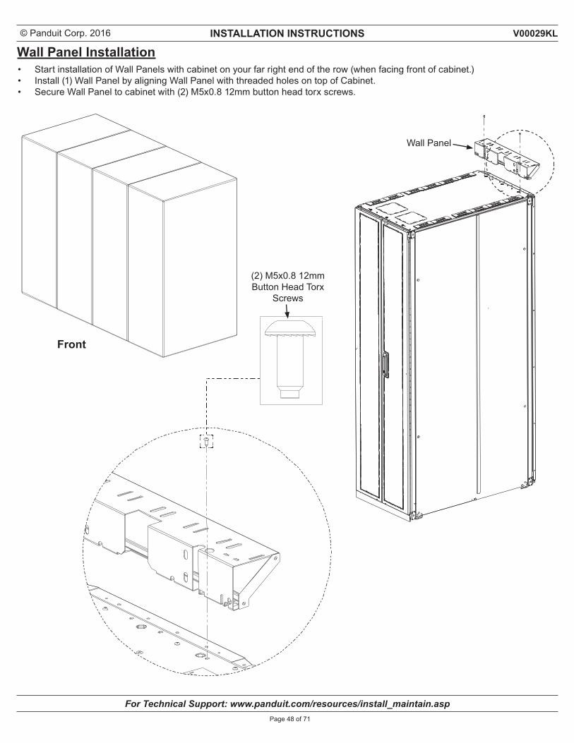
Wall Panel Installation• Start installation of Wall Panels with cabinet on your far right end of the row (when facing front of cabinet.)• Install (1) Wall Panel by aligning Wall Panel with threaded holes on top of Cabinet.• Secure Wall Panel to cabinet with (2) M5x0.8 12mm button head torx screws.
Front
(2) M5x0.8 12mmButton Head Torx
Screws
Wall Panel
© Panduit Corp. 2016 INSTALLATION INSTRUCTIONS
For Technical Support: www.panduit.com/resources/install_maintain.asp
V00029KL
Page 49 of 71
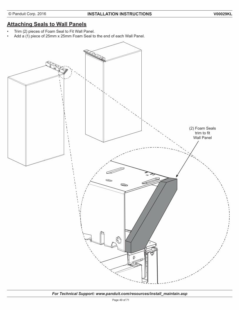
Attaching Seals to Wall Panels• Trim (2) pieces of Foam Seal to Fit Wall Panel.• Add a (1) piece of 25mm x 25mm Foam Seal to the end of each Wall Panel.
(2) Foam Seals trim to fit
Wall Panel
© Panduit Corp. 2016 INSTALLATION INSTRUCTIONS
For Technical Support: www.panduit.com/resources/install_maintain.asp
V00029KL
Page 50 of 71
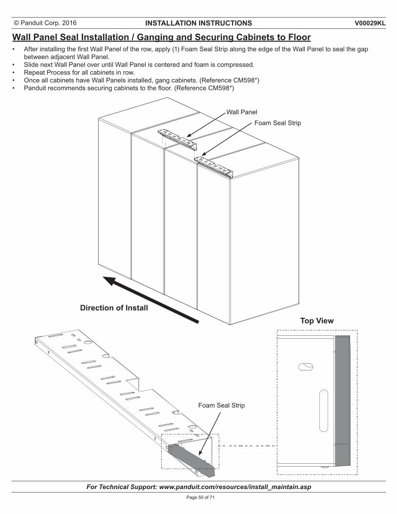
Wall Panel Seal Installation / Ganging and Securing Cabinets to Floor• After installing the first Wall Panel of the row, apply (1) Foam Seal Strip along the edge of the Wall Panel to seal the gap
between adjacent Wall Panel.• Slide next Wall Panel over until Wall Panel is centered and foam is compressed.• Repeat Process for all cabinets in row.• Once all cabinets have Wall Panels installed, gang cabinets. (Reference CM598*)• Panduit recommends securing cabinets to the floor. (Reference CM598*)
Direction of Install
Wall Panel
Top View
Foam Seal Strip
Foam Seal Strip
© Panduit Corp. 2016 INSTALLATION INSTRUCTIONS
For Technical Support: www.panduit.com/resources/install_maintain.asp
V00029KL
Page 51 of 71
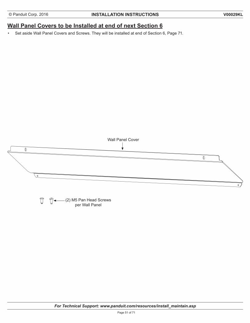
Wall Panel Covers to be Installed at end of next Section 6• Set aside Wall Panel Covers and Screws. They will be installed at end of Section 6, Page 71.
Wall Panel Cover
(2) M5 Pan Head Screws per Wall Panel
© Panduit Corp. 2016 INSTALLATION INSTRUCTIONS
For Technical Support: www.panduit.com/resources/install_maintain.asp
V00029KL
Page 52 of 71
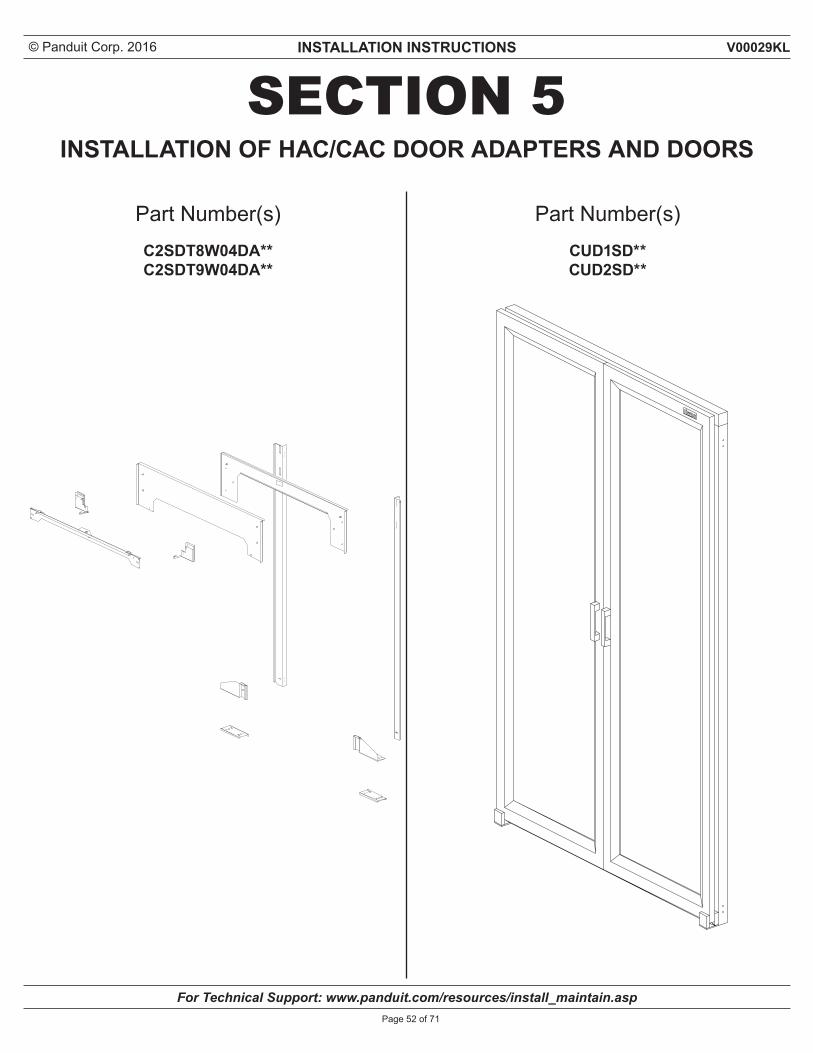
SECTION 5
Part Number(s)C2SDT8W04DA** C2SDT9W04DA**
INSTALLATION OF HAC/CAC DOOR ADAPTERS AND DOORS
Part Number(s)CUD1SD**CUD2SD**
© Panduit Corp. 2016 INSTALLATION INSTRUCTIONS
For Technical Support: www.panduit.com/resources/install_maintain.asp
V00029KL
Page 53 of 71
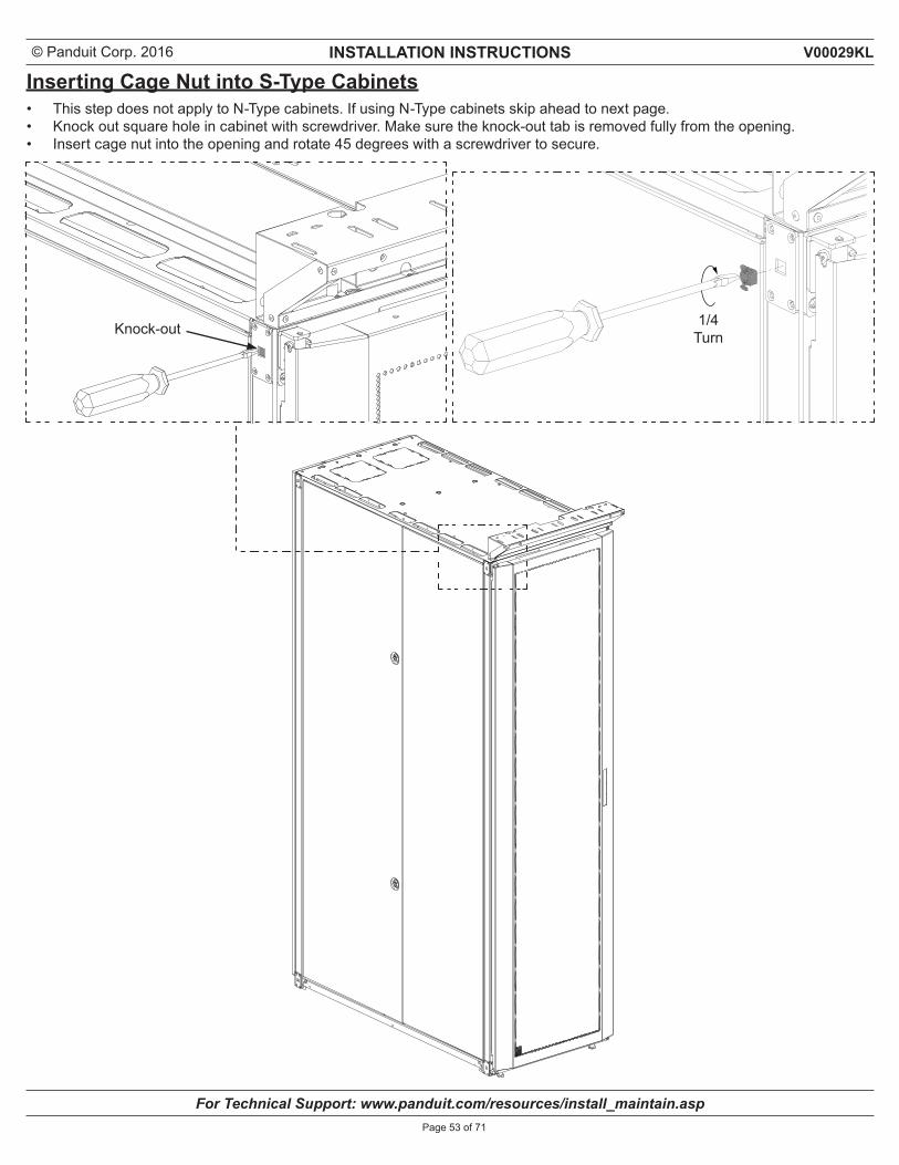
Inserting Cage Nut into S-Type Cabinets• This step does not apply to N-Type cabinets. If using N-Type cabinets skip ahead to next page.• Knock out square hole in cabinet with screwdriver. Make sure the knock-out tab is removed fully from the opening.• Insert cage nut into the opening and rotate 45 degrees with a screwdriver to secure.
Knock-out 1/4 Turn
© Panduit Corp. 2016 INSTALLATION INSTRUCTIONS
For Technical Support: www.panduit.com/resources/install_maintain.asp
V00029KL
Page 54 of 71
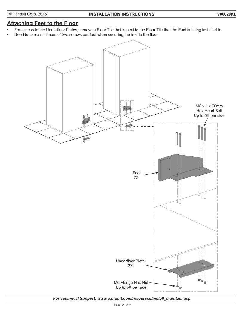
Attaching Feet to the Floor• For access to the Underfloor Plates, remove a Floor Tile that is next to the Floor Tile that the Foot is being installed to.• Need to use a minimum of two screws per foot when securing the feet to the floor.
Underfloor Plate 2X
Foot 2X
M6 Flange Hex Nut Up to 5X per side
M6 x 1 x 70mmHex Head Bolt
Up to 5X per side
© Panduit Corp. 2016 INSTALLATION INSTRUCTIONS
For Technical Support: www.panduit.com/resources/install_maintain.asp
V00029KL
Page 55 of 71
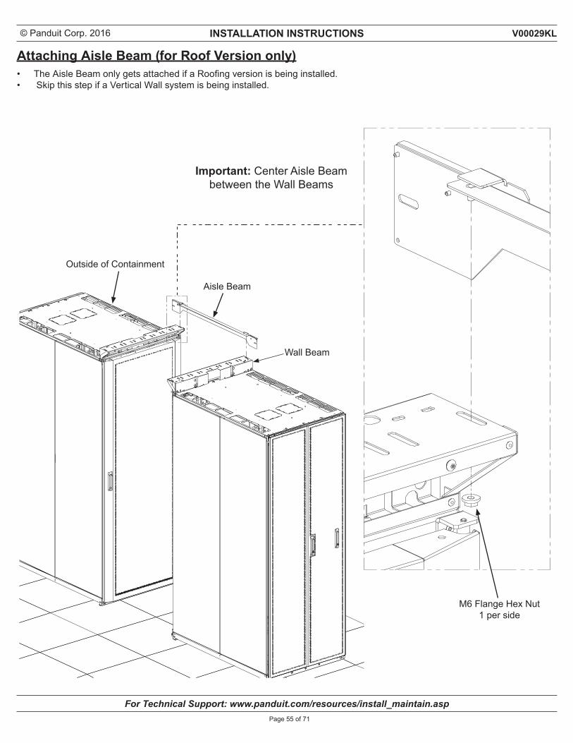
Attaching Aisle Beam (for Roof Version only)• The Aisle Beam only gets attached if a Roofing version is being installed.• Skip this step if a Vertical Wall system is being installed.
M6 Flange Hex Nut 1 per side
Aisle Beam
Outside of Containment
Wall Beam
Important: Center Aisle Beam between the Wall Beams
© Panduit Corp. 2016 INSTALLATION INSTRUCTIONS
For Technical Support: www.panduit.com/resources/install_maintain.asp
V00029KL
Page 56 of 71
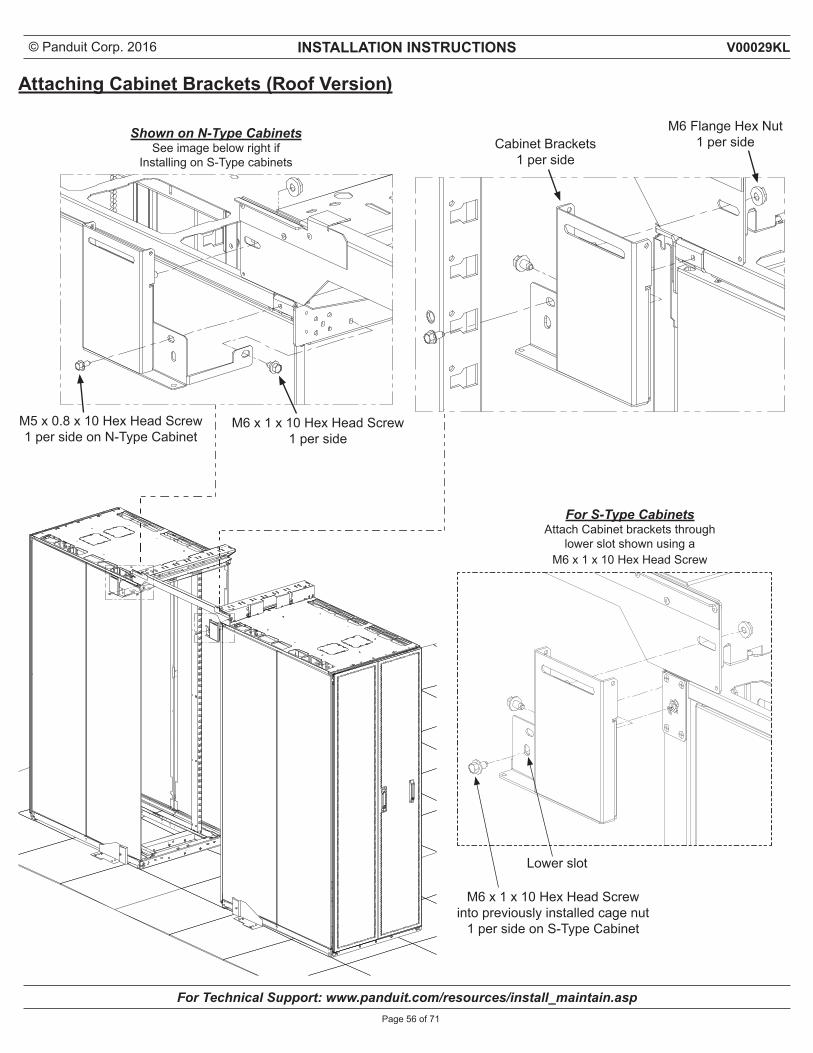
Attaching Cabinet Brackets (Roof Version)
M6 Flange Hex Nut 1 per side
M5 x 0.8 x 10 Hex Head Screw 1 per side on N-Type Cabinet
M6 x 1 x 10 Hex Head Screw 1 per side
Cabinet Brackets1 per side
M6 x 1 x 10 Hex Head Screwinto previously installed cage nut
1 per side on S-Type Cabinet
For S-Type Cabinets Attach Cabinet brackets through
lower slot shown using a M6 x 1 x 10 Hex Head Screw
Shown on N-Type CabinetsSee image below right if
Installing on S-Type cabinets
Lower slot
© Panduit Corp. 2016 INSTALLATION INSTRUCTIONS
For Technical Support: www.panduit.com/resources/install_maintain.asp
V00029KL
Page 57 of 71
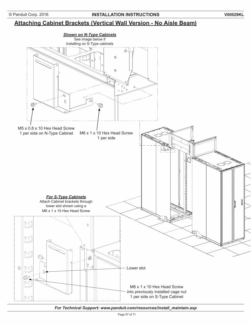
Attaching Cabinet Brackets (Vertical Wall Version - No Aisle Beam)
M5 x 0.8 x 10 Hex Head Screw 1 per side on N-Type Cabinet M6 x 1 x 10 Hex Head Screw
1 per side
M6 x 1 x 10 Hex Head Screwinto previously installed cage nut
1 per side on S-Type Cabinet
For S-Type Cabinets Attach Cabinet brackets through
lower slot shown using a M6 x 1 x 10 Hex Head Screw
Shown on N-Type CabinetsSee image below if
Installing on S-Type cabinets
Lower slot
© Panduit Corp. 2016 INSTALLATION INSTRUCTIONS
For Technical Support: www.panduit.com/resources/install_maintain.asp
V00029KL
Page 58 of 71
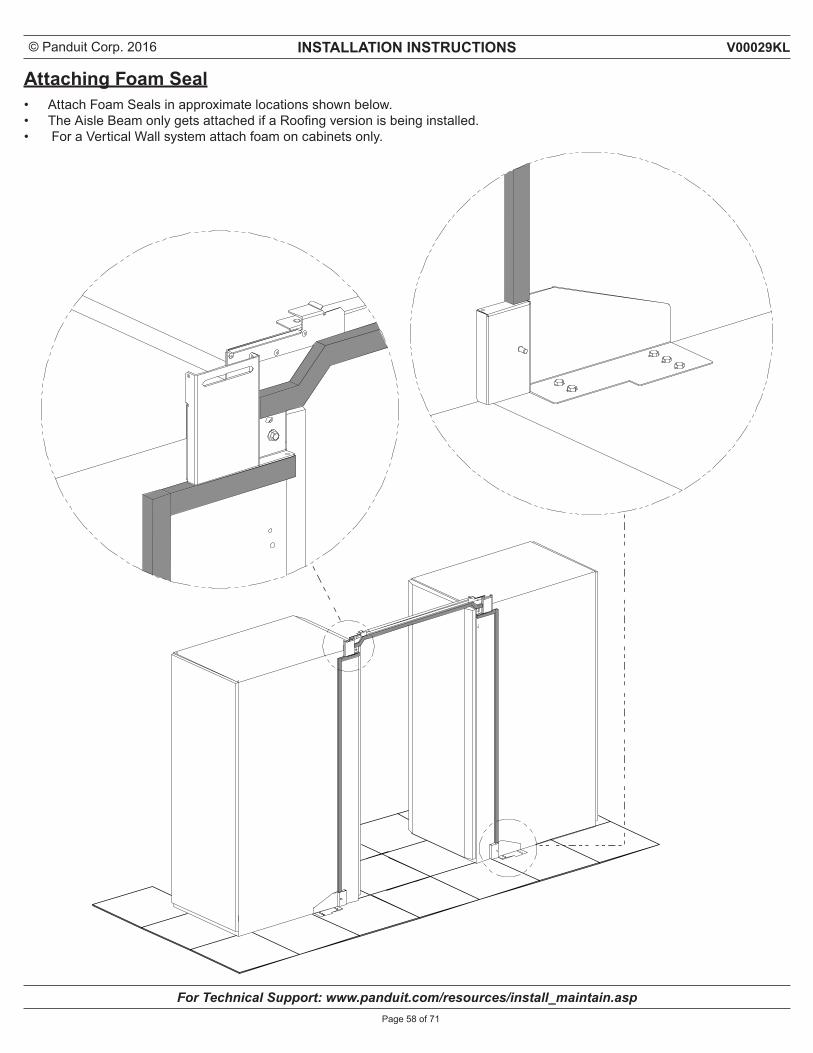
Attaching Foam Seal• Attach Foam Seals in approximate locations shown below.• The Aisle Beam only gets attached if a Roofing version is being installed.• For a Vertical Wall system attach foam on cabinets only.
© Panduit Corp. 2016 INSTALLATION INSTRUCTIONS
For Technical Support: www.panduit.com/resources/install_maintain.asp
V00029KL
Page 59 of 71
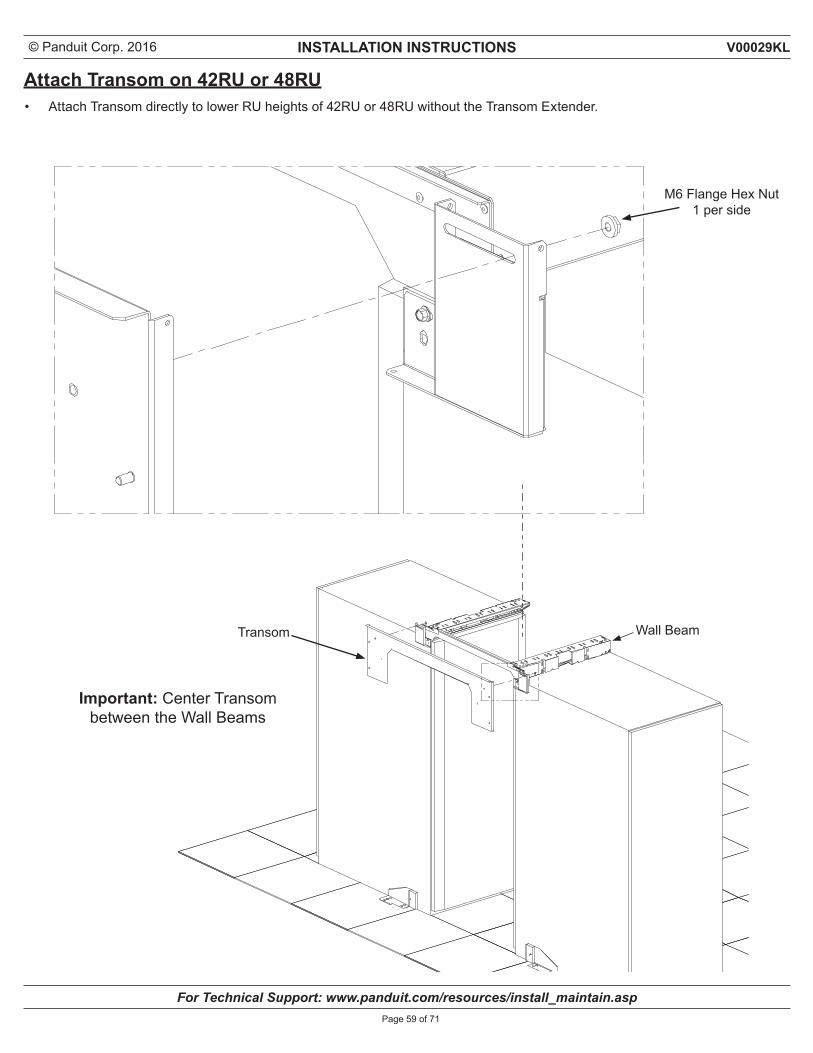
Attach Transom on 42RU or 48RU
M6 Flange Hex Nut 1 per side
• Attach Transom directly to lower RU heights of 42RU or 48RU without the Transom Extender.
Transom
Important: Center Transom between the Wall Beams
Wall Beam
© Panduit Corp. 2016 INSTALLATION INSTRUCTIONS
For Technical Support: www.panduit.com/resources/install_maintain.asp
V00029KL
Page 60 of 71
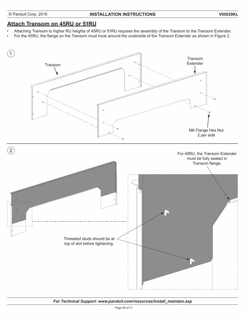
Attach Transom on 45RU or 51RU
M6 Flange Hex Nut 2 per side
• Attaching Transom to higher RU heights of 45RU or 51RU requires the assembly of the Transom to the Transom Extender.• For the 45RU, the flange on the Transom must hook around the underside of the Transom Extender as shown in Figure 2.
TransomTransom Extender
For 45RU, the Transom Extender must be fully seated in
Transom flange.
Threaded studs should be at top of slot before tightening.
1
2
© Panduit Corp. 2016 INSTALLATION INSTRUCTIONS
For Technical Support: www.panduit.com/resources/install_maintain.asp
V00029KL
Page 61 of 71
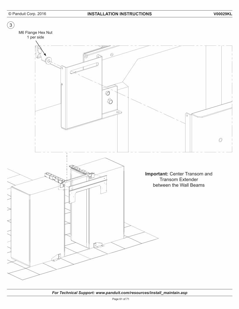
M6 Flange Hex Nut 1 per side
3
Important: Center Transom and Transom Extender
between the Wall Beams
© Panduit Corp. 2016 INSTALLATION INSTRUCTIONS
For Technical Support: www.panduit.com/resources/install_maintain.asp
V00029KL
Page 62 of 71
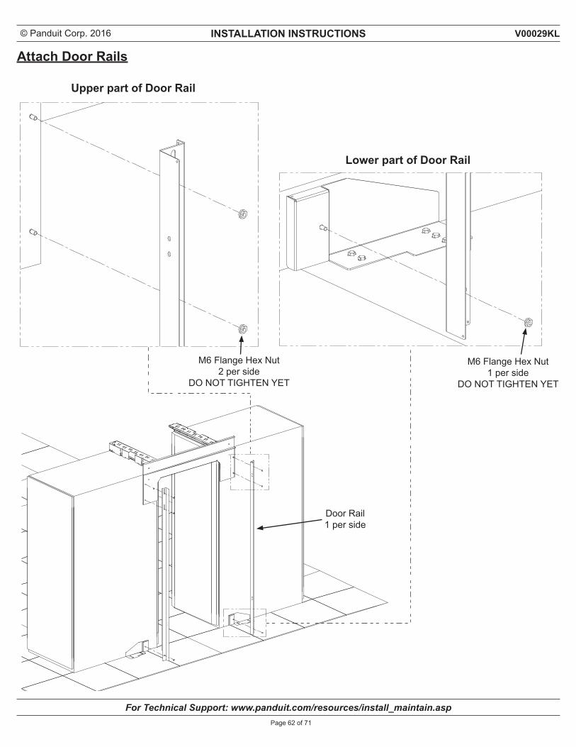
Attach Door Rails
M6 Flange Hex Nut 2 per side
DO NOT TIGHTEN YET
M6 Flange Hex Nut 1 per side
DO NOT TIGHTEN YET
Upper part of Door Rail
Lower part of Door Rail
Door Rail1 per side
© Panduit Corp. 2016 INSTALLATION INSTRUCTIONS
For Technical Support: www.panduit.com/resources/install_maintain.asp
V00029KL
Page 63 of 71
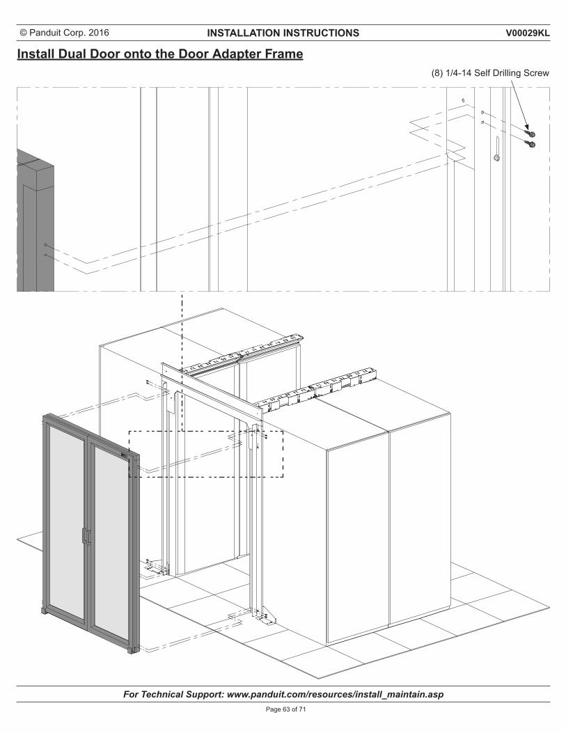
Install Dual Door onto the Door Adapter Frame(8) 1/4-14 Self Drilling Screw
© Panduit Corp. 2016 INSTALLATION INSTRUCTIONS
For Technical Support: www.panduit.com/resources/install_maintain.asp
V00029KL
Page 64 of 71
SECTION 6Part Number(s)C2CAC06F04IR**C2CAC07F04IR** C2CAC08F04IR**
INSTALLATION OF CEILING STRUCTURE
© Panduit Corp. 2016 INSTALLATION INSTRUCTIONS
For Technical Support: www.panduit.com/resources/install_maintain.asp
V00029KL
Page 65 of 71
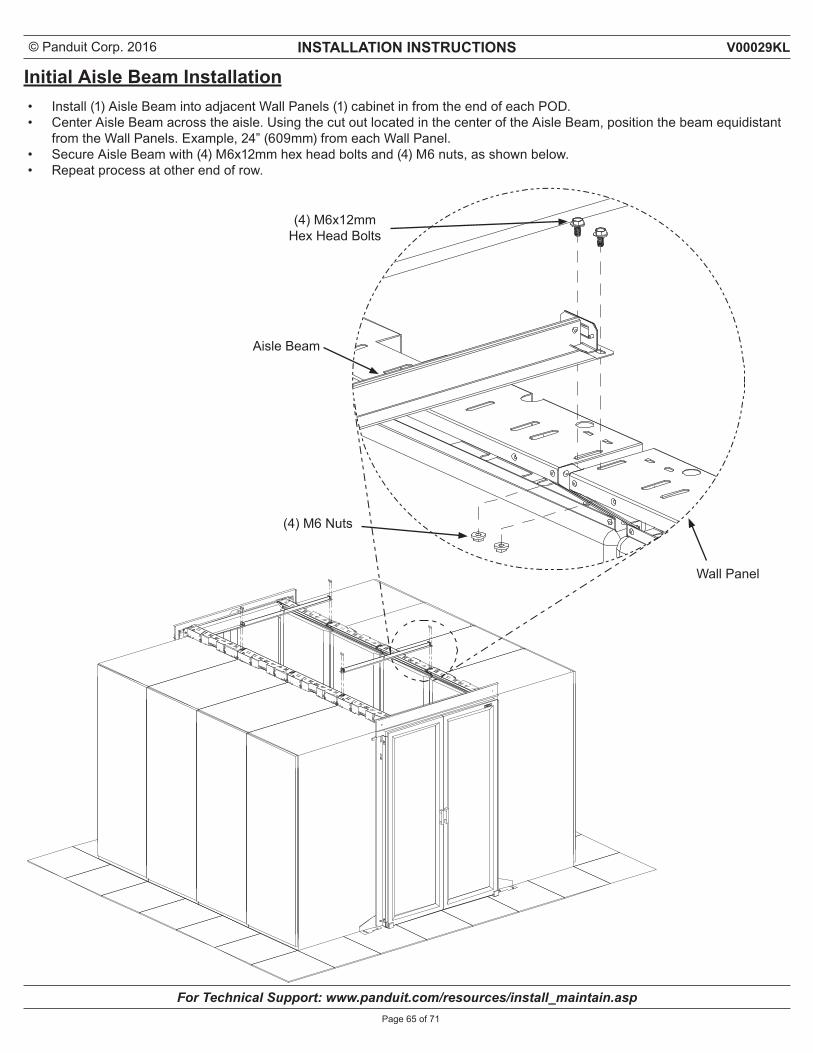
Initial Aisle Beam Installation• Install (1) Aisle Beam into adjacent Wall Panels (1) cabinet in from the end of each POD.• Center Aisle Beam across the aisle. Using the cut out located in the center of the Aisle Beam, position the beam equidistant
from the Wall Panels. Example, 24” (609mm) from each Wall Panel.• Secure Aisle Beam with (4) M6x12mm hex head bolts and (4) M6 nuts, as shown below.• Repeat process at other end of row.
Aisle Beam
Wall Panel
(4) M6 Nuts
(4) M6x12mmHex Head Bolts
© Panduit Corp. 2016 INSTALLATION INSTRUCTIONS
For Technical Support: www.panduit.com/resources/install_maintain.asp
V00029KL
Page 66 of 71
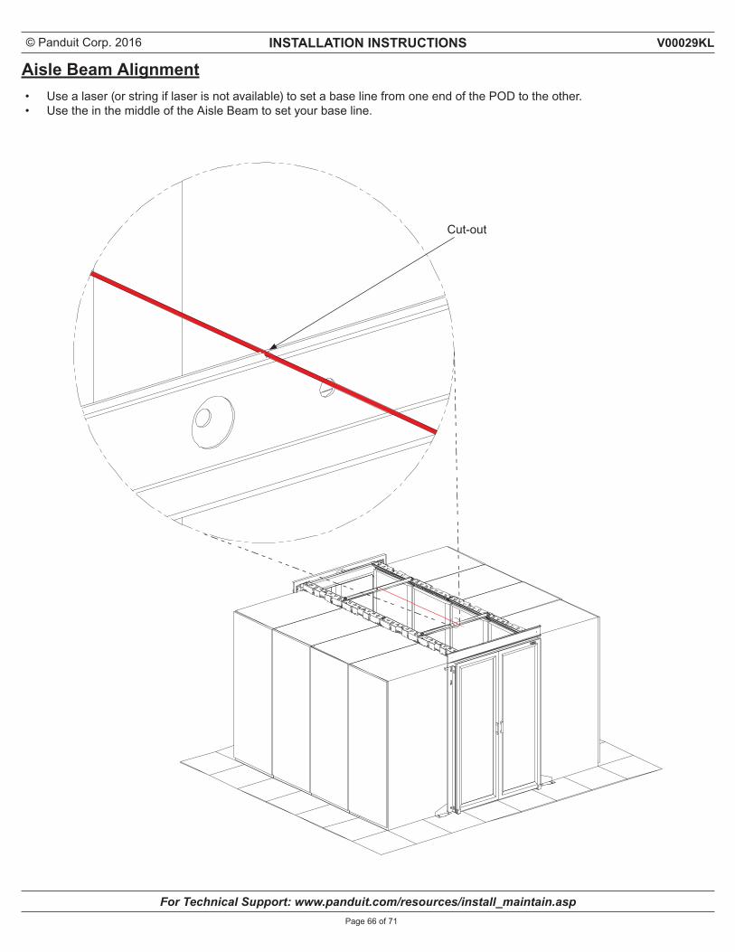
Aisle Beam Alignment• Use a laser (or string if laser is not available) to set a base line from one end of the POD to the other.• Use the in the middle of the Aisle Beam to set your base line.
Cut-out
© Panduit Corp. 2016 INSTALLATION INSTRUCTIONS
For Technical Support: www.panduit.com/resources/install_maintain.asp
V00029KL
Page 67 of 71
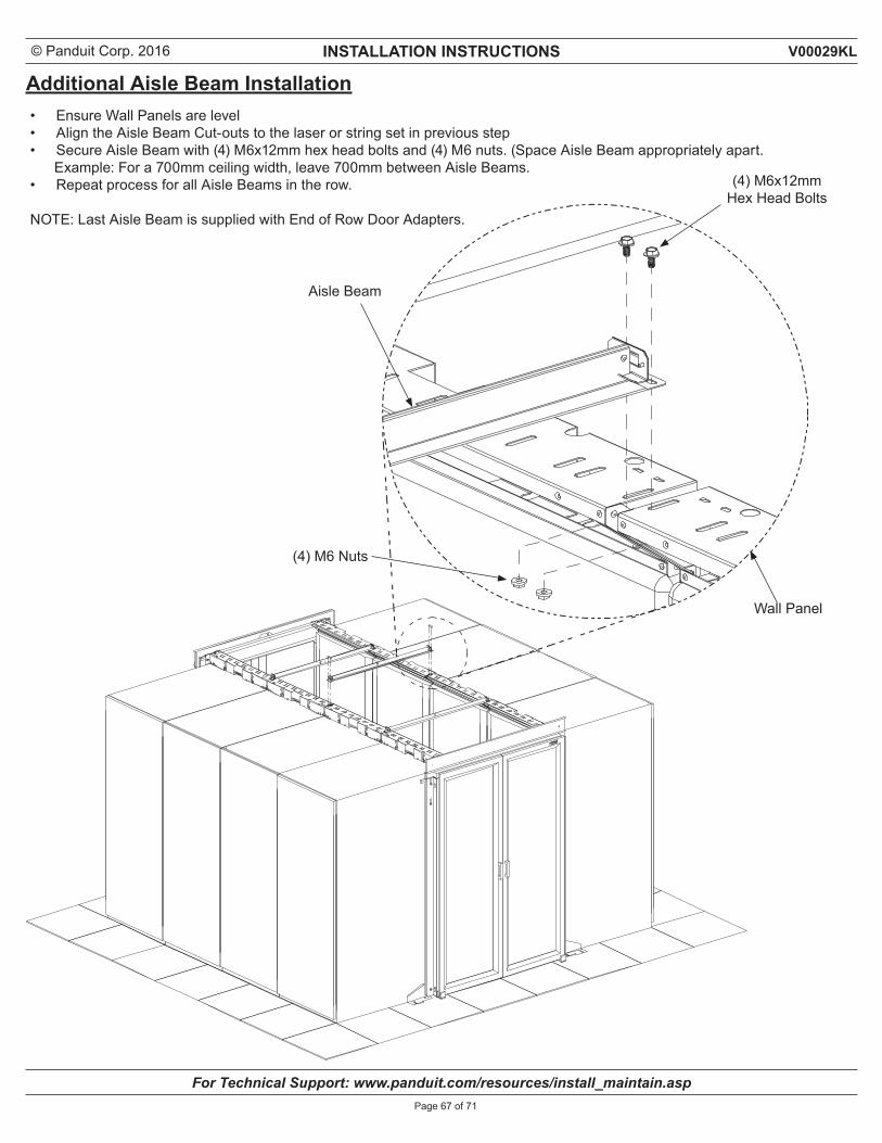
Additional Aisle Beam Installation• Ensure Wall Panels are level• Align the Aisle Beam Cut-outs to the laser or string set in previous step• Secure Aisle Beam with (4) M6x12mm hex head bolts and (4) M6 nuts. (Space Aisle Beam appropriately apart. Example: For a 700mm ceiling width, leave 700mm between Aisle Beams. • Repeat process for all Aisle Beams in the row. NOTE: Last Aisle Beam is supplied with End of Row Door Adapters.
Aisle Beam
Wall Panel
(4) M6 Nuts
(4) M6x12mmHex Head Bolts
© Panduit Corp. 2016 INSTALLATION INSTRUCTIONS
For Technical Support: www.panduit.com/resources/install_maintain.asp
V00029KL
Page 68 of 71
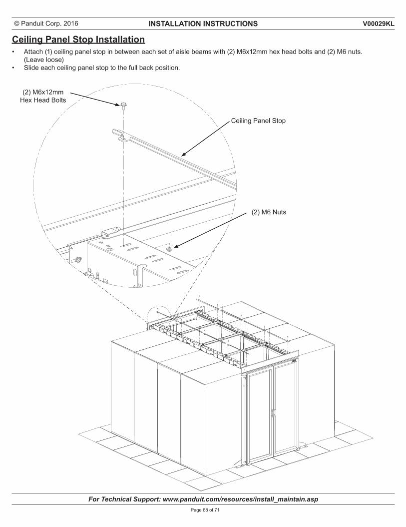
Ceiling Panel Stop Installation• Attach (1) ceiling panel stop in between each set of aisle beams with (2) M6x12mm hex head bolts and (2) M6 nuts.
(Leave loose) • Slide each ceiling panel stop to the full back position.
(2) M6 Nuts
(2) M6x12mmHex Head Bolts
Ceiling Panel Stop
© Panduit Corp. 2016 INSTALLATION INSTRUCTIONS
For Technical Support: www.panduit.com/resources/install_maintain.asp
V00029KL
Page 69 of 71
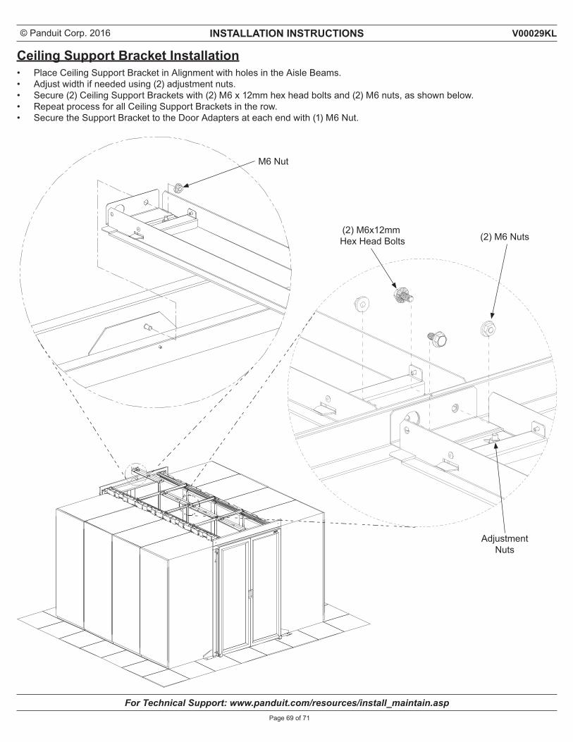
Ceiling Support Bracket Installation• Place Ceiling Support Bracket in Alignment with holes in the Aisle Beams.• Adjust width if needed using (2) adjustment nuts.• Secure (2) Ceiling Support Brackets with (2) M6 x 12mm hex head bolts and (2) M6 nuts, as shown below.• Repeat process for all Ceiling Support Brackets in the row.• Secure the Support Bracket to the Door Adapters at each end with (1) M6 Nut.
(2) M6 Nuts
Adjustment Nuts
(2) M6x12mm Hex Head Bolts
M6 Nut
© Panduit Corp. 2016 INSTALLATION INSTRUCTIONS
For Technical Support: www.panduit.com/resources/install_maintain.asp
V00029KL
Page 70 of 71
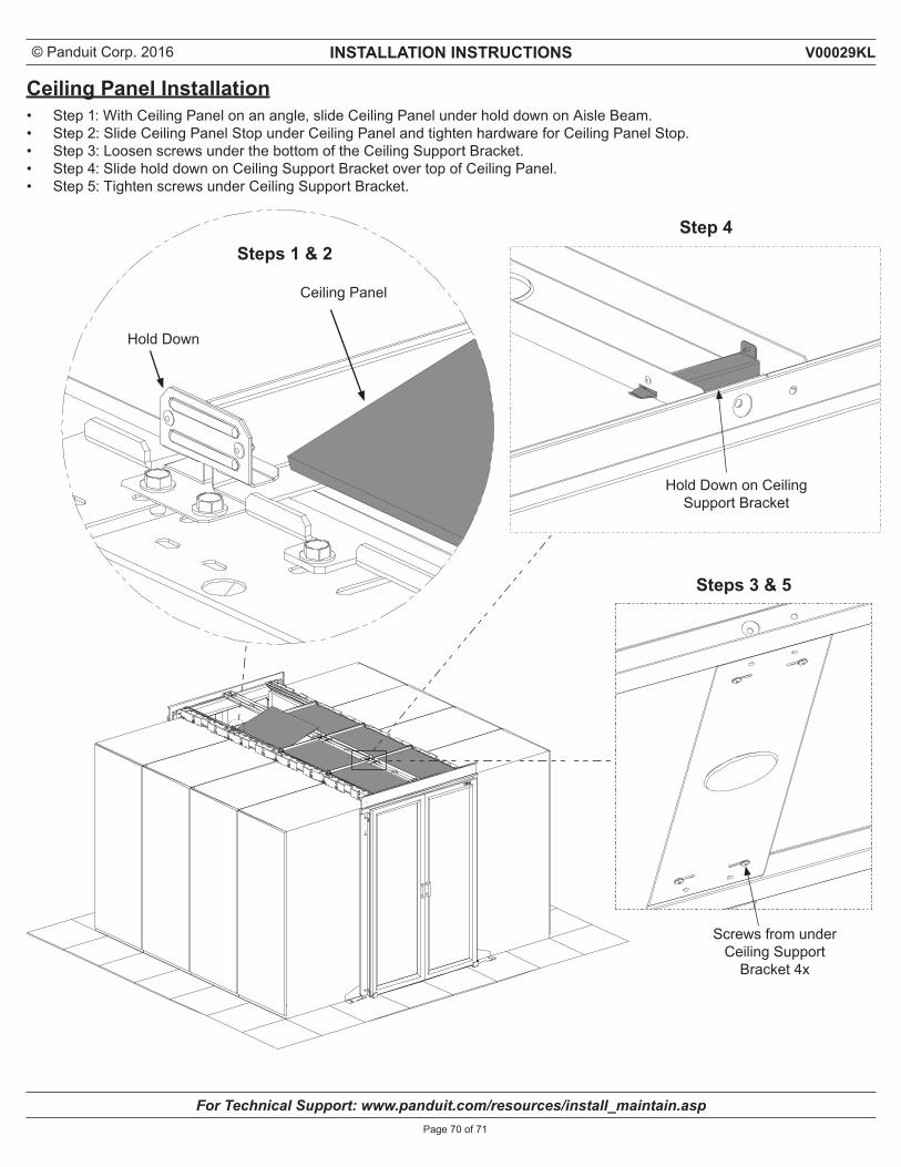
Ceiling Panel Installation• Step 1: With Ceiling Panel on an angle, slide Ceiling Panel under hold down on Aisle Beam.• Step 2: Slide Ceiling Panel Stop under Ceiling Panel and tighten hardware for Ceiling Panel Stop.• Step 3: Loosen screws under the bottom of the Ceiling Support Bracket.• Step 4: Slide hold down on Ceiling Support Bracket over top of Ceiling Panel.• Step 5: Tighten screws under Ceiling Support Bracket.
Hold Down
Ceiling Panel
Steps 1 & 2Step 4
Steps 3 & 5
Hold Down on Ceiling Support Bracket
Screws from under Ceiling Support
Bracket 4x
© Panduit Corp. 2016 INSTALLATION INSTRUCTIONS V00029KL
Page 71 of 71
For Instructions in Local Languages and Technical Support:
www.panduit.com/resources/install_maintain.asp
E-mail:[email protected]
Phone:866-405-6654www.panduit.com
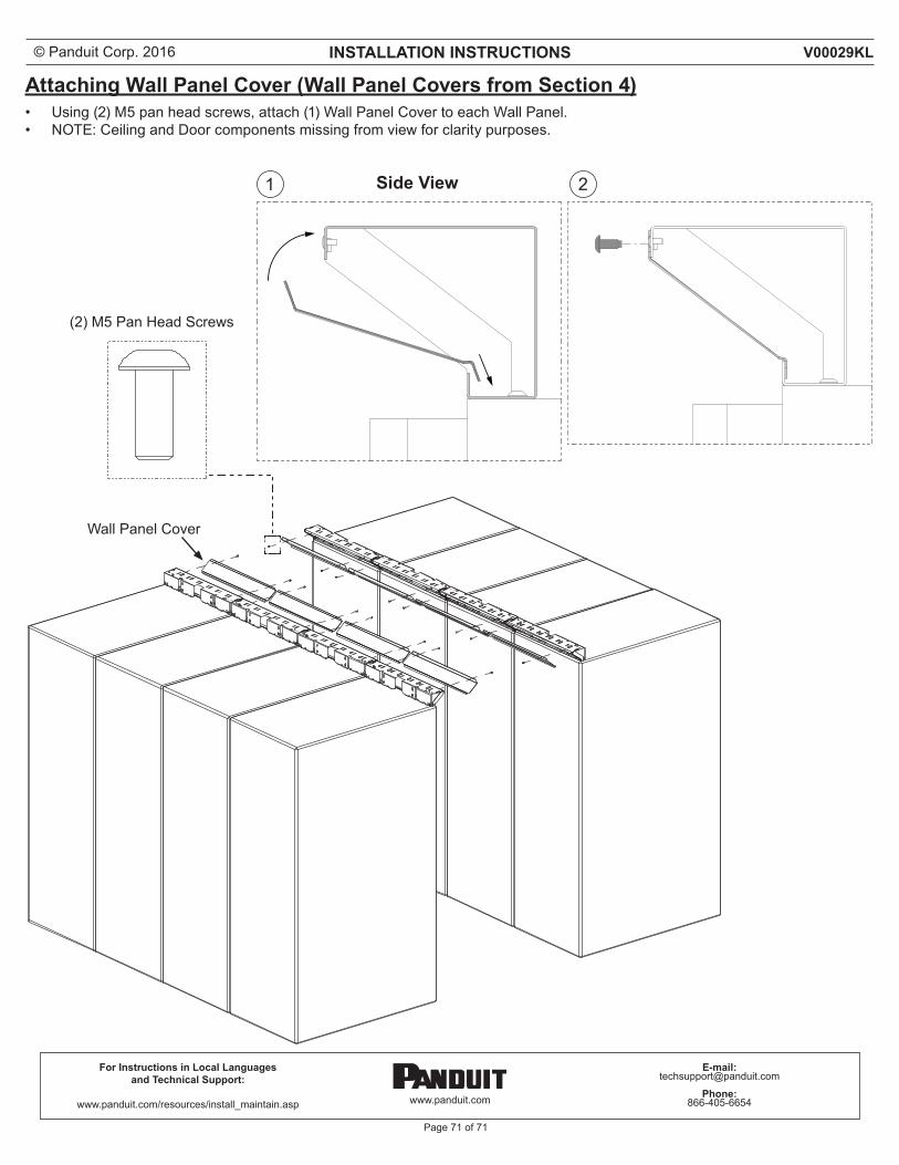
Attaching Wall Panel Cover (Wall Panel Covers from Section 4)• Using (2) M5 pan head screws, attach (1) Wall Panel Cover to each Wall Panel.• NOTE: Ceiling and Door components missing from view for clarity purposes.
(2) M5 Pan Head Screws
Wall Panel Cover
1 2Side View