4. Electrical Transmission 4-1 - California Energy · PDF fileElectrical Transmission ... due...
32
TABLE OF CONTENTS R:\12 HECA\AFC Amd\4_0 Elec Trans.docx 4-i 4. Electrical Transmission........................................................................ 4-1 4.1 Project Description................................................................................... 4-1 4.2 Route Selection ........................................................................................ 4-1 4.3 Structure Selection ................................................................................... 4-2 4.3.1 General ......................................................................................... 4-2 4.3.2 Structure Weights and Dimensions.............................................. 4-2 4.4 Conductor Selection ................................................................................. 4-2 4.4.1 Introduction .................................................................................. 4-2 4.4.2 Sag and Tension Table ................................................................. 4-3 4.4.3 Conductor Electrical and Mechanical Characteristics ................. 4-3 4.5 Optical Ground Wire................................................................................ 4-3 4.5.1 Optical Ground Wire Selection.................................................... 4-3 4.6 Insulator Selection ................................................................................... 4-3 4.7 Comparison of Tubular Structures and Lattice Towers ........................... 4-4 4.7.1 Lattice Structures ......................................................................... 4-4 4.7.2 Tangent Structures ....................................................................... 4-4 4.8 Construction Methods and Impacts ......................................................... 4-4 4.8.1 Construction Methods .................................................................. 4-4 4.8.2 Permanent Right-of-Way ............................................................. 4-5 4.8.3 Land Disturbance during Construction ........................................ 4-5 4.9 Electric and Magnetic Effects .................................................................. 4-6 4.9.1 Introduction .................................................................................. 4-6 4.9.2 Mitigation of Electric and Magnetic Effects ................................ 4-7 4.9.3 Assumptions for Electrical and Magnetic Effects Calculations.................................................................................. 4-8 4.9.4 Results .......................................................................................... 4-9 4.10 Aviation Safety ........................................................................................ 4-9 4.11 Environmental Consequences ................................................................ 4-10 4.12 Applicable Laws, Ordinances, Regulations, and Standards .................. 4-10 4.12.1 Design and Construction ............................................................ 4-10 4.12.2 Electric and Magnetic Fields ..................................................... 4-11 4.12.3 Hazardous Shock ....................................................................... 4-11 4.12.4 Communication Interference ..................................................... 4-11 4.12.5 Aviation Safety .......................................................................... 4-11 4.12.6 Fire Hazard................................................................................. 4-11 4.12.7 Project Transmission Line Jurisdiction...................................... 4-11
-
Upload
dangnguyet -
Category
Documents
-
view
218 -
download
2
Transcript of 4. Electrical Transmission 4-1 - California Energy · PDF fileElectrical Transmission ... due...
TABLE OF CONTENTS
R:\12 HECA\AFC Amd\4_0 Elec Trans.docx 4-i
4. Electrical Transmission ........................................................................ 4-1
4.1 Project Description ................................................................................... 4-1 4.2 Route Selection ........................................................................................ 4-1 4.3 Structure Selection ................................................................................... 4-2
4.3.1 General ......................................................................................... 4-2 4.3.2 Structure Weights and Dimensions .............................................. 4-2
4.4 Conductor Selection ................................................................................. 4-2 4.4.1 Introduction .................................................................................. 4-2 4.4.2 Sag and Tension Table ................................................................. 4-3 4.4.3 Conductor Electrical and Mechanical Characteristics ................. 4-3
4.5 Optical Ground Wire................................................................................ 4-3 4.5.1 Optical Ground Wire Selection .................................................... 4-3
4.6 Insulator Selection ................................................................................... 4-3 4.7 Comparison of Tubular Structures and Lattice Towers ........................... 4-4
4.7.1 Lattice Structures ......................................................................... 4-4 4.7.2 Tangent Structures ....................................................................... 4-4
4.8 Construction Methods and Impacts ......................................................... 4-4 4.8.1 Construction Methods .................................................................. 4-4 4.8.2 Permanent Right-of-Way ............................................................. 4-5 4.8.3 Land Disturbance during Construction ........................................ 4-5
4.9 Electric and Magnetic Effects .................................................................. 4-6 4.9.1 Introduction .................................................................................. 4-6 4.9.2 Mitigation of Electric and Magnetic Effects ................................ 4-7 4.9.3 Assumptions for Electrical and Magnetic Effects
Calculations.................................................................................. 4-8 4.9.4 Results .......................................................................................... 4-9
4.10 Aviation Safety ........................................................................................ 4-9 4.11 Environmental Consequences ................................................................ 4-10 4.12 Applicable Laws, Ordinances, Regulations, and Standards .................. 4-10
4.12.1 Design and Construction ............................................................ 4-10 4.12.2 Electric and Magnetic Fields ..................................................... 4-11 4.12.3 Hazardous Shock ....................................................................... 4-11 4.12.4 Communication Interference ..................................................... 4-11 4.12.5 Aviation Safety .......................................................................... 4-11 4.12.6 Fire Hazard ................................................................................. 4-11 4.12.7 Project Transmission Line Jurisdiction ...................................... 4-11
TABLE OF CONTENTS
4-ii R:\12 HECA\AFC Amd\4_0 Elec Trans.docx
Tables
Table 4-1 Tangent Structure Table 4-2 Deadend Structure Table 4-3 Characteristics of Bittern ACSR
Table 4-4 Characteristics of the Optical Ground Wire Table 4-5 Comparison of Lattice and Tubular Steel Structures Table 4-6 Conductor Geometry Table 4-7 Audible Noise Levels Table 4-8 Electric Fields Table 4-9 Magnetic Fields Table 4-10 Radio Influence Table 4-11 Design and Construction LORS Table 4-12 Electric and Magnetic Fields Table 4-13 Hazardous Shock LORS Table 4-14 Communications Interference LORS Table 4-15 Aviation Safety LORS Table 4-16 Fire Hazard LORS Table 4-17 Jurisdiction
Figures
Figure 4-1 Route Alternatives Figure 4–2 Tangent Structure Figure 4–3 Deadend Structure Figure 4-4 Sag and Tension Data – Bittern Figure 4–5 Sag and Tension Data – GW4810 Figure 4–6 Rodurflex Insulating Crossarm Figure 4–7 Combined Load Chart Figure 4–8 Conductor Location Diagram Figure 4–9 Audible Noise Figure 4–10 Electric Field Figure 4–11 Magnetic Field Figure 4–12 Radio Influence
SECTIONFOUR Electrical Transmission
R:\12 HECA\AFC Amd\4_0 Elec Trans.docx 4-1
4. Section 4 Electrical Transmission
4.1 PROJECT DESCRIPTION
Hydrogen Energy California LLC (HECA LLC) is proposing an Integrated Gasification Combined Cycle (IGCC) polygeneration project (hereafter referred to as HECA or the Project). The Project intends to connect to the Pacific Gas and Electric Company (PG&E) Midway Substation via 230-kilovolt (kV) Midway–Wheeler Ridge transmission line and a new PG&E switching station. The PG&E Midway–Wheeler Ridge lines were selected as the Project’s preferred interconnection point because of its proximity to the Project Site, accessibility, and to avoid the significant congestion at the Midway Substation identified in previous studies and reports. Additional details pertaining to the Large-Generator Interconnection Procedure (LGIP) are included in Appendix C. The new PG&E switching station will be approximately 2 miles east of the Project Site. A 230-kV, single-pole, double-circuit capacity transmission line is planned to connect the Project to the PG&E switching station. This line is to be constructed using a single-shaft, galvanized tubular-steel structure with a braced-post insulation system. One circuit will be on each side of the structure. Deadend and angle structures will be similar tubular-steel structures with horizontal davit arms to hold the conductors. The line will incorporate two optical shield wires. These will be used for both operational communications for the power line and for lightning shielding.
4.2 ROUTE SELECTION
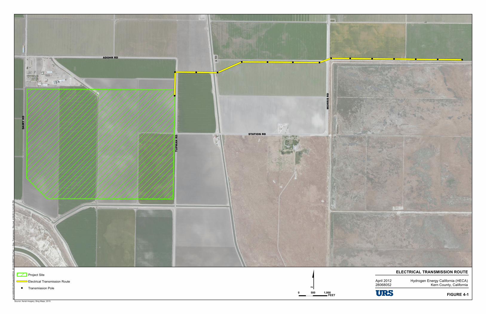
The transmission line route between the Project Site and the new PG&E switching station to connect the Project with PG&E via the existing Midway–Wheeler Ridge 230 kV lines is shown on Figure 4-1, Route Alternatives.
The transmission-line route leaves the Project Site east to Tupman Road, continuing north to near Adohr Road, then east to the new PG&E switching station near Elk Valley Road.
Considerations for the selection of this route are listed below:
Feasibility of Land Acquisition. This route involves a minimum number of landowners. Negotiations with them by the Project have been successful in gaining agreements for the transmission line rights-of-way.
Safety and Proximity to Potential Sensitive Receptors (i.e., residences, schools, daycare centers, etc.). There are no residences or other occupied buildings along the entire route.
Overall Economic Feasibility. Due to the close proximity of the interconnection point with the Project Site, the identified route provides the shortest and most direct transmission line available. Options of interconnecting directly with the Midway Substation were reviewed; due to identified congestion in and around the substation, as well as the considerably longer line length, those options were eliminated.
The Project will build the transmission line to result in a less-than-significant impact.
Appendix C, Transmission Network Upgrade, describes the status of the Project’s Interconnection Study, currently ongoing with the California Independent System Operator
SECTIONFOUR Electrical Transmission
4-2 R:\12 HECA\AFC Amd\4_0 Elec Trans.docx
(CAISO), which is assessing the feasibility and associated impacts of providing the grid connection for the Project.
4.3 STRUCTURE SELECTION
4.3.1 General
The type of transmission-line structure was selected based on aesthetics, economics, ease of construction, and to minimize the effect on the land for crop production after construction is complete. The Project has selected the single-pole, tangent structure because this structure has less potential impact on the environment than the lattice steel tower structure.
An example drawing of the single-pole, tangent structure is shown on Figure 4-2, Tangent Structure. An example deadend structure is shown on Figure 4-3, Deadend Structure. The single-pole, tangent structure with braced-post insulators is an attractive alternative to a lattice steel tower. This pole design blends in with the surrounding area, as it is similar to an existing 230-kV line near the Project Site.
The single-pole, tangent structure is economical to fabricate, deliver, and erect. Because it is built in two or three pieces, it can be delivered by truck. Construction requires only one foundation, unlike a lattice structure. A lattice structure also has many small pieces that must be fabricated individually and then assembled at the site. This is further discussed in Section 4.7, Comparison of Tubular Structures and Lattice Towers.
The single-pole, tangent structures, once erected, take up less ground area at the base of each pole. The single-pole structure requires approximately a 6- to 8-foot-diameter area at the base; whereas a four-legged lattice structure may require a 25- or 30-foot-square area. The space within the lattice structure, between the legs, is not usable for crop production.
4.3.2 Structure Weights and Dimensions
Table 4-1, Tangent Structure, shows the approximate height and weight for a typical tangent structure used on this Project. Table 4-2, Deadend Structure, shows the height and weight for a deadend structure.
4.4 CONDUCTOR SELECTION
4.4.1 Introduction
The conductor selected for the preliminary design is 1,272-thousand-circular-mil (kcmil) aluminum conductor steel-reinforced stranding (ACSR). This conductor is also referred to as Bittern ACSR. The ACSR class of conductor has been in use since the 1930s. The overall diameter of the conductor is approximately 1.35inches.
The selection of this conductor considered several factors, including ampacity, weight, strength, sag, cost, application, and consistency with the Project objectives. Bittern ACSR was selected based on these factors. Other conductor types considered included aluminum-steel–supported
SECTIONFOUR Electrical Transmission
R:\12 HECA\AFC Amd\4_0 Elec Trans.docx 4-3
conductor with trapezoidal stranding for the aluminum strands (ACSS), and aluminum conductor composite core (ACCC) conductor family. ACCC conductors have an outer layer of annealed trapezoidal strands and an inner layer consisting of polymer-bound carbon fibers encased in a fiberglass tube. No steel is used. The cost of ACCC is about three times the cost of ACSR. With no significant advantages of ACCC or ACSS over ACSR, the widely used Bittern ACSR conductor type was selected.
4.4.2 Sag and Tension Table
The sag and tension table for the Bittern conductor is shown on Figure 4-4, Sag and Tension Data – Bittern.
4.4.3 Conductor Electrical and Mechanical Characteristics
The conductor characteristics are described in Table 4-3, Characteristics of Bittern ACSR.
4.5 OPTICAL GROUND WIRE
4.5.1 Optical Ground Wire Selection
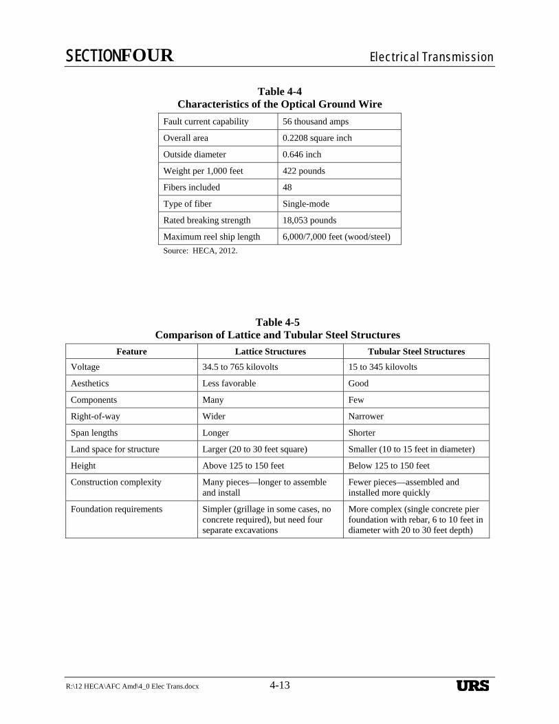
Currently, two optical ground wires (OPGW) are planned. The OPGW conductor selected is an outer layer of alternating aluminum-clad steel and aluminum wire strands, an aluminum pipe and stainless-steel tube under the outer layer, and 48 strands of single-mode optical fiber inside the stainless tube. The OPGW has the characteristics as shown in Table 4-4, Characteristics of the Optical Ground Wire.
The sag and tension table for the OPGW is shown on Figure 4-5, Sag and Tension Data – GW4810.
The OPGW positioning will be designed to provide 30-degree shielding for lightning protection of the transmission conductors.
4.6 INSULATOR SELECTION
The insulator configuration for the tangent structures is a braced post insulator assembly. The braced-post assembly consists of a horizontal post insulator with an additional insulator extending from the end of the horizontal post insulator up at an angle to the pole. This type of insulation system was selected based on aesthetics to match a similar line in the area of the proposed line. It was also selected to meet the electrical insulation characteristics and mechanical strength requirements necessary to support the selected conductor. This insulation system allows for an attractive, economical, and compact design. These insulators are available from at least three suppliers. A drawing of a typical braced-post insulator assembly is shown on Figure 4-6, Rodurflex Insulating Crossarm. The corresponding combined-loading chart is shown on Figure 4-7, Combined-Load Chart.

SECTIONFOUR Electrical Transmission
4-4 R:\12 HECA\AFC Amd\4_0 Elec Trans.docx
4.7 COMPARISON OF TUBULAR STRUCTURES AND LATTICE TOWERS
4.7.1 Lattice Structures
Single-pole, tangent structures (fabricated from steel) and lattice steel towers are both commonly used for transmission line supporting structures. The lattice steel towers have been around for many years and have been used for lines from 35 kV through 765 kV. Steel poles have gained popularity more recently and are generally used for 15 kV to 345 kV lines. The lattice structure has been used where larger loads, more line-to-ground clearance, or longer spans are desired. Lattice structures tend to be more economical when larger and taller structures are required. Lattice structures tend to be used in rural or open, unpopulated areas where spans can be lengthened. Towers come in many small pieces. Each of the many pieces must be separately manufactured. At each site, each piece must be tracked, accounted for, and assembled into the finished tower. The tower legs take up much more space than the tapered pole, and the space within the legs typically cannot be used for crop production.
4.7.2 Tangent Structures
The Project intends to use single-pole, tangent structures for the transmission towers for the reasons listed below. Single-pole, tangent structures—also known as tapered-steel-pole structures—present a much cleaner appearance than the lattice-type structures. The most common finish on steel poles is simply bare galvanizing. The galvanizing on the pole, although initially appearing as a bright, shiny surface, will rapidly fade to a dull gray appearance. Allowing the steel to oxidize can also be used as a method to blend the pole structure into the surrounding features while, at the same time, the oxidation protects the steel from corrosion. Steel-pole structures have been largely accepted by the public as being more aesthetically pleasing than the lattice-type structures. However, the public is more accepting of the same type of structures being used on the same right-of-way (ROW). The mixing of steel poles and lattice structures causes a perceived visual conflict. The pole structure tends to accent the size and complexity of the adjacent lattice structure, and the presence of the lattice structures detract from the simplicity of the steel-pole structure.
A subjective comparison of various features of the lattice and tubular-steel structures is shown in Table 4-5, Comparison of Lattice and Tubular Steel Structures.
4.8 CONSTRUCTION METHODS AND IMPACTS
4.8.1 Construction Methods
Construction of the line will require installing approximately 26 (15 off site and 11 on site) tubular-steel transmission structures and the supporting foundations. Construction will also involve stringing the conductor and OPGW. After the line is completed, regular preventive maintenance and inspections will be required. An occasional unscheduled repair may also be required.
The line will be built using conventional methods with off-road heavy equipment. The heavy equipment will include truck-mounted foundation-hole drilling equipment, dump trucks, flat-bed tractor-trailer units to bring in reinforcing cages and other supplies, concrete trucks, and

SECTIONFOUR Electrical Transmission
R:\12 HECA\AFC Amd\4_0 Elec Trans.docx 4-5
concrete-pumping trucks. Truck-mounted mobile cranes will be required to set the structures. Smaller support vehicles such as pickups and other service vehicles will also be required. Medium-sized earth-moving equipment will be needed to load surplus spoil material for removal from the site. Specialized truck-mounted equipment will be used for pulling in and sagging the conductors and shield wires.
Temporary primitive roads will need to be constructed within the transmission line ROW, except where the line runs parallel to existing roads. A small area around each structure site will need to be disturbed temporarily during the construction period. Diagrams of the construction sites at each structure, wire stringing (pulling) sites, and other temporary construction areas can be better defined once a final route option and preliminary line design is available. The approximate area that may be temporarily disturbed is quantified in Section 4.8.3. Roadway matting may be used on the road and around the area of each structure to minimize the effects of the construction vehicles and the construction activity. The construction is likely to impact the crop production for a relatively short period of time. Because the time to construct the entire transmission line is estimated to be approximately 3 months, crop production may be impacted intermittently during this time.
After construction has been completed, the line will require a minimal amount of maintenance. Most of the maintenance will be routine and can be scheduled during periods when damage to the crops and the land can be minimized. Maintenance activities can be planned to occur during the dryer periods of the year to minimize soil and crop damage. Again, roadway matting may be used to reduce crop and soil damage, if necessary.
When construction and maintenance activities have been completed, any soil and crop damage can be repaired by tilling to loosen the soil and then replanting.
4.8.2 Permanent Right-of-Way
A typical 230-kV transmission line ROW for this type of line is 100 feet wide, 50 feet on each side. A 100-foot-wide ROW is assumed for the Project design. The total acreage for this ROW would be approximately 25.5 acres, based on a 2.1-mile total line route; however, the permanent disturbance would be comprised only of the poles.
A 6-foot-diameter area will be needed permanently at the base of each structure. Assuming 26 structures, (15 off site and 11 on site), the total area affected will be only about 745 square feet total (424 square feet off site [0.01 acre] and 311 square feet on site).
4.8.3 Land Disturbance during Construction
During construction, an up-to-25-foot-diameter area around each structure will be required to install the structure foundation and to set the structure. Assuming 15 structures off site (26 total), the off-site area disturbed for this activity will be approximately 3.8 acres.
In addition to the area above, construction vehicles will need to drive the ROW for construction. This will require a total area of approximately 6.4 acres, assuming a 25-foot-wide temporary roadway along the entire line, based on a 2.1-mile line route. Part of the line may be adjacent to
SECTIONFOUR Electrical Transmission
4-6 R:\12 HECA\AFC Amd\4_0 Elec Trans.docx
existing roadways. In these areas, it is possible that no temporary roadway will be required. This will reduce the total acreage required for roadway stated above.
Potential impacts associated with the construction and maintenance of the transmission line are addressed by discipline (e.g., biological, cultural, visual) in the respective sections of this AFC Amendment.
4.9 ELECTRIC AND MAGNETIC EFFECTS
4.9.1 Introduction
The electric and magnetic effects studied included audible noise, electric fields, magnetic fields, and radio influence.
Audible noise and radio influence are effects caused by corona. Corona is a luminous discharge caused by ionization of the air surrounding an energized conductor, conductor fittings, and connectors. These discharges are caused by the voltage gradient at the discharge points exceeding a certain critical value.
Corona discharges are affected by altitude, humidity, weather, line voltage, conductor irregularities on the surfaces of the conductors, and the shape of and irregularities on conductor fittings and connectors. The configuration and spacing of the line conductors also has an effect.
Corona effects can be controlled by carefully selecting line conductors and other components for the Project during the detailed design process. Also, corona discharges can be controlled by carefully handling the conductor to prevent damage and surface irregularities. Care should also be taken to make sure that unprotected sharp edges such as conductor ends are not left after the construction is complete.
The most effective approach that can be used during the preliminary design to minimize corona effects is to select an appropriate conductor. For this preliminary design, a conductor with a diameter of approximately 1.35 inches was selected. For 230 kV, at the altitude of this Project (less than 500 feet), the minimum conductor diameter considered appropriate is approximately 1.11 inches. Audible noise is the crackling sound that a person hears when standing under or near a transmission line. This noise will vary in amplitude (intensity) and will lessen with the observer’s increased distance from the line. The amplitude will also vary, increasing during periods of high humidity in the air and precipitation, including rain, sleet, and snow. Again, the noise will decrease as the observer moves away from the line.
Radio influence is the buzzing and crackling one might hear coming from the speaker of an amplitude modulation (AM) broadcast receiver. The influence is typically observed when listening to an AM broadcast band receiver near a transmission line. Nearby amateur radio stations using AM signal receivers may possibly also experience, to a lesser extent, the radio influence from the line. Amateur radio stations typically use higher frequencies. The radio influence is attenuated more quickly as the received frequency and distance from the transmission line is increased. Frequency modulation (FM) modulated signals, unless very weak, will not be affected by the line. With the advent of, and increased use of, new
SECTIONFOUR Electrical Transmission
R:\12 HECA\AFC Amd\4_0 Elec Trans.docx 4-7
technologies such as digital radio, digital television, satellite radio, and MP3 players, the significance of the radio influence has greatly diminished.
The U.S. Federal Communications Commission, in the Code of Federal Regulations (CFR) 47, Part 15, designates electrical lines as incidental emitters of radio frequency signals. These emitters must not interfere with licensed communications services that are operating in their designated service area. Should interference occur, the emitting source is responsible for mitigating the interference. In general, interference from transmission lines in lightly populated areas has not proven to be a significant issue.
Electric and magnetic fields are produced during the operation of a transmission line. These fields are not heard as audible or radio noise. However, the electric and magnetic fields may be experienced in other ways. For example, a person may experience a tingling of the skin or a frizzing of the hair when near a transmission line. A person entering or exiting a vehicle parked under a transmission line may experience a noticeable but innocuous shock as the person touches the vehicle. Voltages can be induced into fences, railroad tracks, waterlines, etc., which are of concern but can be mitigated successfully.
An alternating electric field is generated by the voltage on the energized conductors of the transmission line. Because this line is a double-circuit line, there are six conductors, one for each phase of a three-phase circuit, and two circuits. Conductors at the top of the structure are also used for lightning protection and communications. These conductors are not energized and are not considered in the electric field calculations.
The electric field near the ground produced by the transmission line is influenced by the voltage of the line, the number and configuration of the conductors in relationship to each other and the ground, and the electrical phasing of the conductors in one circuit compared to the other circuit. The electric field strength will be different if one or two circuits are energized.
An alternating magnetic field is generated by the current flowing in the energized conductors of the transmission line. The magnetic field is influenced by the current flowing in the line, as well as the other factors mentioned in the electric field paragraph above. The line voltage is not a direct factor for the magnetic field. The magnetic field strength will be different if one or two circuits are energized and loaded.
4.9.2 Mitigation of Electric and Magnetic Effects
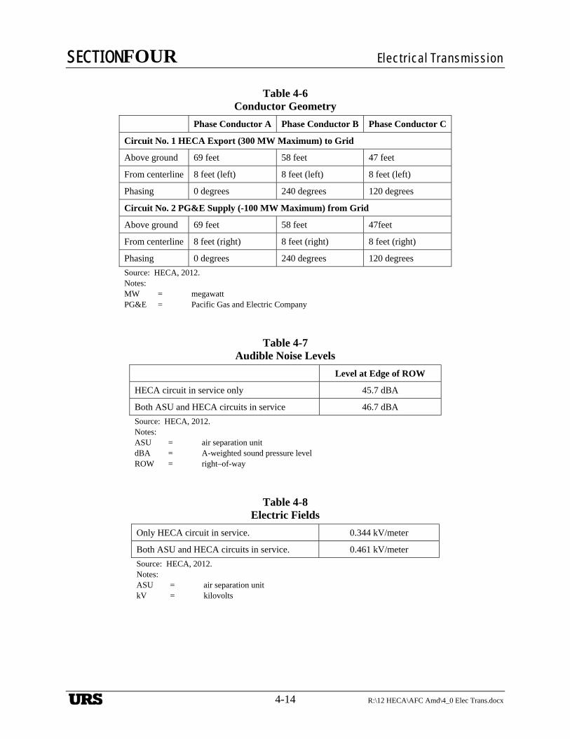
The State of California requires no-cost or low-cost mitigation of the effects of transmission lines. In the case of electric and magnetic effects, mitigation was performed in two basic ways. First, because the power flows of the two circuits are in opposite directions, the same top-to-bottom phasing arrangement of the conductors leads to the lowest magnetic fields. The phasing of the conductors for each circuit in relationship to the other circuit is shown in the assumptions table, Table 4-6, Conductor Geometry. The phasing arrangement shown has the effect of lowering the magnetic fields while increasing the electric field, audible noise and radio influence levels. So, one must decide which of the conditions are most important and merit being reduced.
SECTIONFOUR Electrical Transmission
4-8 R:\12 HECA\AFC Amd\4_0 Elec Trans.docx
Another way the preliminary design has attempted to lower the electric and magnetic field levels is to move the conductors away from the observer. This is accomplished when additional clearance above that which is required is provided. The California General Order 95 (GO-95) requires a minimum conductor clearance to ground of 30 feet for a 230-kV line. The preliminary line design calls for a clearance of 40 feet for a 700-foot span. The additional clearance is also included to make it more difficult for farm machinery and other farming operations to contact or to come close to the conductors.
4.9.3 Assumptions for Electrical and Magnetic Effects Calculations
Several assumptions must be made to predict the levels for each of the electric and magnetic effects. These assumptions are described below.
Table 4-6, Conductor Geometry, describes the configuration, geometry, and phasing of the conductors on the transmission line.
Only the potential electric and magnetic effects of the subject transmission line are considered in this analysis. The existing electric and magnetic fields (EMFs) at the Project Site boundary were assumed to be zero, because the Project Site is in a rural undeveloped area without facilities in close proximity that might emit such EMFs.
A diagram for this geometry is shown on Figure 4-8, Conductor Location Diagram.
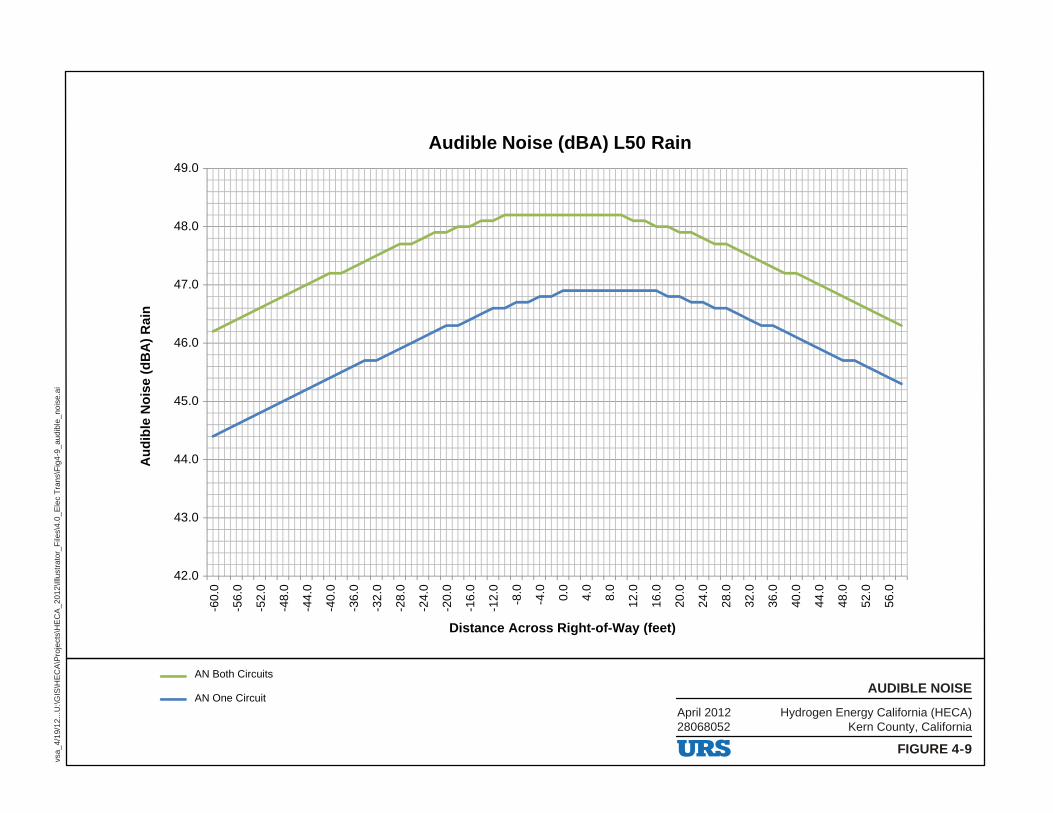
The audible noise calculations assume an L50 rain condition, which is not a heavy rain but a moderate, steady rain. The audible noise calculation assumes a system voltage of 242 kV, which is 105 percent of the nominal 230-kV system voltage. The calculations also assume an altitude of 500 feet or less for the Project. Calculations are made for 5 feet above ground, which corresponds to the approximate height of a human ear. This is also the typical elevation used for the sensor for a measuring instrument. The calculations have been run for two conditions: when one circuit is in service and when both circuits are in service.
Similarly, the electric field calculations assume a system voltage of 242 kV and a Project altitude of less than 500 feet. The calculation assumes a height of 3.28 feet above the ground. Calculations for one circuit in service and two circuits in service were performed.
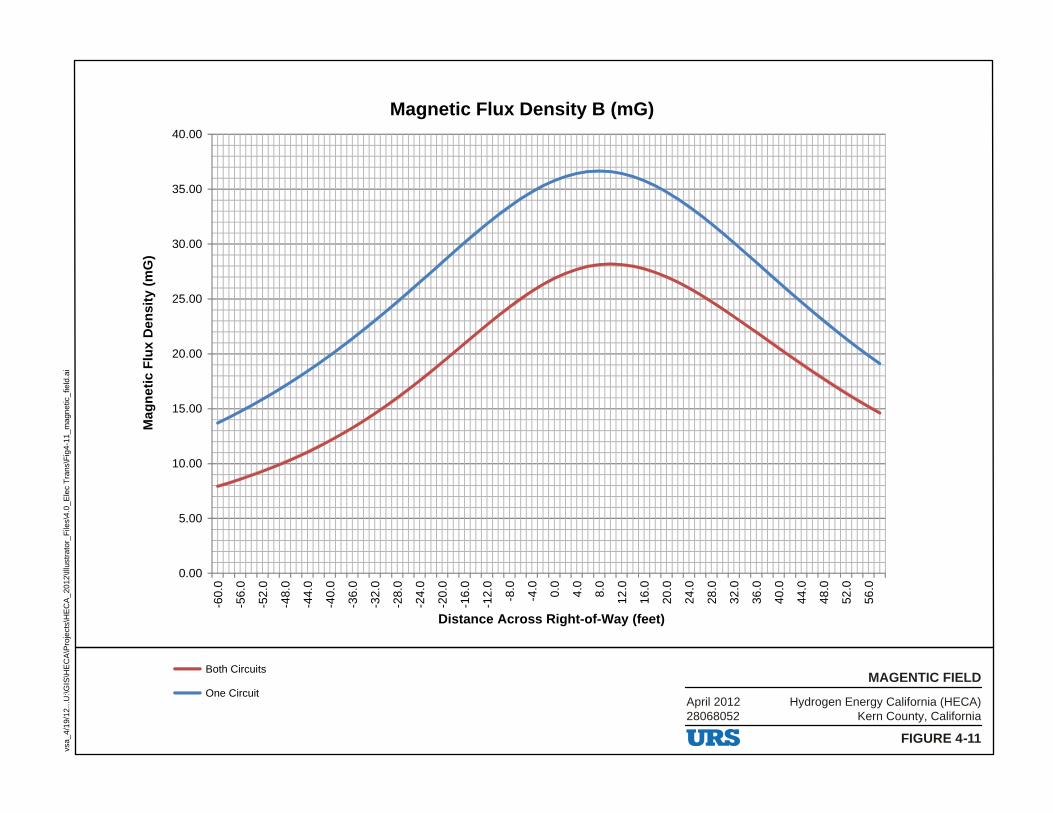
The magnetic field calculations were performed using the maximum current available based on the net output of the facility. Using the plant’s net capacity of 300 megawatts (MW) and a power factor of 0.90, the maximum line current is calculated as 837 amps. Two calculations were performed, one with both transmission line circuits in service, and one calculation with only one generator circuit in service. With only one generator line in service, 837 amps will flow in one line and the other line will have no current flow. The Project expects operation with both circuits in service. The condition where only one circuit would be in service would be rare and would occur for a relatively short period of time. The magnetic field calculations assume an observer height of 3.28 feet above the ground.
The radio influence calculations were performed assuming a system voltage of 242 kV and a Project altitude of 500 feet or less. The calculations assume an observer height of 3.28 feet

SECTIONFOUR Electrical Transmission
R:\12 HECA\AFC Amd\4_0 Elec Trans.docx 4-9
above the ground. The calculations were conducted at a frequency of 1,000 kilohertz, which is the approximate center of the AM broadcast band in the United States.
4.9.4 Results
The results shown below are for values at the edge of the ROW, which is assumed to be 50 feet from the centerline. Two cases are depicted: first with only the HECA Export Circuit energized and loaded, with the air separation unit (ASU) circuit de-energized and not loaded; second with both HECA and ASU circuits energized and loaded to their maximum planned values, 300 MW and 100 MW, respectively.
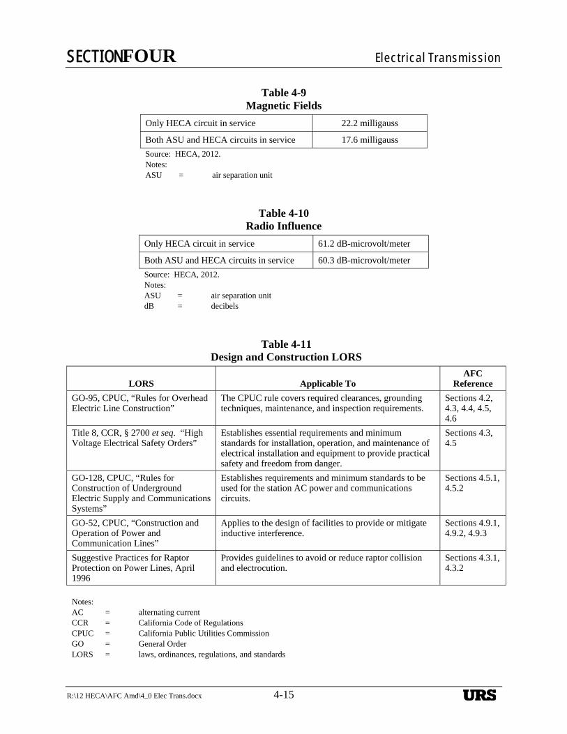
Table 4-7, Audible Noise Levels, shows the audible noise levels for the line at the edge of the ROW. A graph of the audible noise levels is shown on Figure 4-9, Audible Noise.
Table 4-8, Electric Fields, shows the electric field levels for the line at the edge of the ROW. A graph of electric field levels is shown on Figure 4-10, Electric Field.
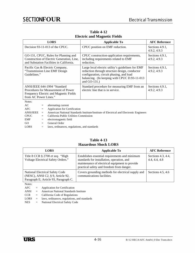
Table 4-9, Magnetic Fields, shows the magnetic field levels for the line at the edge of the ROW. A graph of the magnetic field levels is shown on Figure 4-11, Magnetic Field.
Table 4-10, Radio Influence, shows the radio influence levels for the line at the edge of the ROW. A graph of the radio influence levels is shown on Figure 4-12, Radio Influence.
The Project will not cause any significant human health impacts related to EMF exposure. No state standards exist for EMF exposure, and available evidence has not established a link between EMF exposure and significant health impacts. Long-term residential EMF exposure from the proposed Project lines will be reduced with the implementation of design and management measures recommended by the California Public Utilities Commission (CPUC) to reduce EMF exposure. On-site worker or public exposure will be short term and at levels expected for lines of similar design and current-carrying capacity, which does not pose a significant human health hazard. As a result, impacts related to EMF exposure will be less than significant.
4.10 AVIATION SAFETY
Federal Aviation Administration (FAA) Regulations, Title 14 CFR, Part 77, establishes standards for determining obstructions in navigable airspace in the vicinity of airports that are available for public use and are listed in the Airport/Facility Directory. These regulations set forth requirements for notification of proposed obstruction that extends above the earth’s surface. FAA notification is required for any potential obstruction structure erected over 200 feet in height above ground level. Notification is required if the obstruction is greater than specified heights and falls within any restricted airspace in the approach to airports. For airports with runways longer than 3,200 feet, the restricted space extends 20,000 feet (3.3 nautical miles) from the runway, with no obstruction greater than a 100:1 ratio of the distance from the runway. For airports with runways measuring 3,200 feet or less, the restricted space extends 10,000 feet (1.7 nautical miles) with a 50:1 ratio of the distance from the runway. For heliports, the restricted space extends 5,000 feet (0.8 nautical mile) with a 25:1 ratio.

SECTIONFOUR Electrical Transmission
4-10 R:\12 HECA\AFC Amd\4_0 Elec Trans.docx
Buttonwillow Airport is the sole airport within the 20,000-foot restricted space. It is approximately 3.5 miles southwest from the Midway Substation, and the runway length is 3,260 feet. Based on this information, notification will be required only if any structure for the transmission line exceeds approximately 160 feet in height and is 3 miles from the Buttonwillow Airport. As shown on Figure 4-3, the maximum height of the proposed deadend structure is expected to be 115 feet; therefore, the transmission-line structures will not exceed a height of 160 feet.
After the Buttonwillow Airport, the next three airports closest to the Project are the Ford City, Bakersfield, and Gottlieb airports. The Ford City Airport is located approximately 14 miles south of Tupman; the Bakersfield Airport is located approximately 22 miles east of Tupman; and the Gottlieb Airport (private) is located approximately 14 miles east of Buttonwillow. None of these airports is close enough to pose any height notification issues. As a result, impacts related to aviation safety will not be significant.
4.11 ENVIRONMENTAL CONSEQUENCES
The Project transmission line will not result in significant environmental impacts. The Project transmission line and related facilities are not close enough to an airport to pose an aviation hazard according to current FAA criteria. The potential for nuisance shocks will be minimized through grounding the Project’s support structures. There are no permanently occupied buildings along the alignment. EMF, audible noise, and radio influence will be mitigated by constructing the line at least 75 feet from existing occupied buildings and other field-reducing measures required by standard industry practices. Industry standard approaches reasonably ensure that the Project’s lines will not have a significant environmental impact on public health and safety, nor cause any significant impacts related to radio/television communications interference, audible noise, fire hazards, nuisance, or hazardous shocks.
With the implementation of recommended mitigation measures and best management and design practices, the Project will conform with all applicable LORS relating to Transmission Line Safety and Nuisance, and will not result in any significant impacts.
4.12 APPLICABLE LAWS, ORDINANCES, REGULATIONS, AND STANDARDS
This section provides a list of LORS that apply to the interconnecting transmission line and engineering. The following compilation of LORS is in response to Section (h) of Appendix B attached to Article 6, of Chapter 6, of Title 20 of the California Code of Regulations (CCR). Inclusion of these data is further outlined in the California Energy Commission’s (CEC) publication entitled “Rules of Practice and Procedure & Power Plant Site Certification Regulations.”
4.12.1 Design and Construction
Table 4-11, Design and Construction LORS, lists the applicable LORS for the design and construction of the transmission line and substations.

SECTIONFOUR Electrical Transmission
R:\12 HECA\AFC Amd\4_0 Elec Trans.docx 4-11
4.12.2 Electric and Magnetic Fields
The applicable LORS pertaining to electric and magnetic field interference are tabulated in Table 4-12, Electric and Magnetic Fields.
4.12.3 Hazardous Shock
Table 4-13, Hazardous Shock LORS, lists the LORS regarding hazardous shock protection for the Project.
4.12.4 Communication Interference
The applicable LORS pertaining to communication interference are tabulated in Table 4-14, Communications Interference LORS.
4.12.5 Aviation Safety
Table 4-15, Aviation Safety LORS, lists the aviation safety LORS that may apply to the construction and operation of the Project transmission line.
4.12.6 Fire Hazard
Table 4-16, Fire Hazard LORS, tabulates the LORS governing fire hazard protection for the Project transmission line.
4.12.7 Project Transmission Line Jurisdiction
Table 4-17, Jurisdiction, identifies national, state, and local agencies with jurisdiction to issue permits or approvals, conduct inspections, and/or enforce the above-referenced LORS. Table 4-17 also identifies the associated responsibilities of these agencies as they relate to the construction and operation of the Project transmission line.

SECTIONFOUR Electrical Transmission
4-12 R:\12 HECA\AFC Amd\4_0 Elec Trans.docx
Table 4-1 Tangent Structure
Structure height above ground 110 feet
Structure weight 10,000 pounds, including anchor bolts
Source: HECA, 2012.
Table 4-2 Deadend Structure
Structure height above ground 115 feet
Structure weight 23,500 pounds, including anchor bolts
Source: HECA, 2012.
Table 4-3 Characteristics of Bittern ACSR
Cross-sectional area 1,272,000 Kcmil
Outer diameter 1.345 inches
Rated breaking strength 34,100 pounds
Stranding 45/7 (aluminum/steel)
Current rating (25°C ambient) 1184 amps at 75°C
Current rating (25°C ambient) 1,350 amps at 100°C
Current rating (48°C ambient) 797 amps at 75°C
Current rating (48°C ambient) 1,202 amps at 100°C
Source: HECA, 2012. Notes: ACSR = aluminum conductor steel reinforced °C = degrees Celsius kcmil = thousand circular mils
SECTIONFOUR Electrical Transmission
R:\12 HECA\AFC Amd\4_0 Elec Trans.docx 4-13
Table 4-4 Characteristics of the Optical Ground Wire
Fault current capability 56 thousand amps
Overall area 0.2208 square inch
Outside diameter 0.646 inch
Weight per 1,000 feet 422 pounds
Fibers included 48
Type of fiber Single-mode
Rated breaking strength 18,053 pounds
Maximum reel ship length 6,000/7,000 feet (wood/steel)
Source: HECA, 2012.
Table 4-5 Comparison of Lattice and Tubular Steel Structures
Feature Lattice Structures Tubular Steel Structures
Voltage 34.5 to 765 kilovolts 15 to 345 kilovolts
Aesthetics Less favorable Good
Components Many Few
Right-of-way Wider Narrower
Span lengths Longer Shorter
Land space for structure Larger (20 to 30 feet square) Smaller (10 to 15 feet in diameter)
Height Above 125 to 150 feet Below 125 to 150 feet
Construction complexity Many pieces—longer to assemble and install
Fewer pieces—assembled and installed more quickly
Foundation requirements Simpler (grillage in some cases, no concrete required), but need four separate excavations
More complex (single concrete pier foundation with rebar, 6 to 10 feet in diameter with 20 to 30 feet depth)
SECTIONFOUR Electrical Transmission
4-14 R:\12 HECA\AFC Amd\4_0 Elec Trans.docx
Table 4-6 Conductor Geometry
Phase Conductor A Phase Conductor B Phase Conductor C
Circuit No. 1 HECA Export (300 MW Maximum) to Grid
Above ground 69 feet 58 feet 47 feet
From centerline 8 feet (left) 8 feet (left) 8 feet (left)
Phasing 0 degrees 240 degrees 120 degrees
Circuit No. 2 PG&E Supply (-100 MW Maximum) from Grid
Above ground 69 feet 58 feet 47feet
From centerline 8 feet (right) 8 feet (right) 8 feet (right)
Phasing 0 degrees 240 degrees 120 degrees
Source: HECA, 2012. Notes: MW = megawatt PG&E = Pacific Gas and Electric Company
Table 4-7 Audible Noise Levels
Level at Edge of ROW
HECA circuit in service only 45.7 dBA
Both ASU and HECA circuits in service 46.7 dBA
Source: HECA, 2012. Notes: ASU = air separation unit dBA = A-weighted sound pressure level ROW = right–of-way
Table 4-8 Electric Fields
Only HECA circuit in service. 0.344 kV/meter
Both ASU and HECA circuits in service. 0.461 kV/meter
Source: HECA, 2012. Notes: ASU = air separation unit kV = kilovolts
SECTIONFOUR Electrical Transmission
R:\12 HECA\AFC Amd\4_0 Elec Trans.docx 4-15
Table 4-9 Magnetic Fields
Only HECA circuit in service 22.2 milligauss
Both ASU and HECA circuits in service 17.6 milligauss
Source: HECA, 2012. Notes: ASU = air separation unit
Table 4-10 Radio Influence
Only HECA circuit in service 61.2 dB-microvolt/meter
Both ASU and HECA circuits in service 60.3 dB-microvolt/meter
Source: HECA, 2012. Notes: ASU = air separation unit dB = decibels
Table 4-11 Design and Construction LORS
LORS Applicable To AFC
Reference
GO-95, CPUC, “Rules for Overhead Electric Line Construction”
The CPUC rule covers required clearances, grounding techniques, maintenance, and inspection requirements.
Sections 4.2, 4.3, 4.4, 4.5, 4.6
Title 8, CCR, § 2700 et seq. “High Voltage Electrical Safety Orders”
Establishes essential requirements and minimum standards for installation, operation, and maintenance of electrical installation and equipment to provide practical safety and freedom from danger.
Sections 4.3, 4.5
GO-128, CPUC, “Rules for Construction of Underground Electric Supply and Communications Systems”
Establishes requirements and minimum standards to be used for the station AC power and communications circuits.
Sections 4.5.1, 4.5.2
GO-52, CPUC, “Construction and Operation of Power and Communication Lines”
Applies to the design of facilities to provide or mitigate inductive interference.
Sections 4.9.1, 4.9.2, 4.9.3
Suggestive Practices for Raptor Protection on Power Lines, April 1996
Provides guidelines to avoid or reduce raptor collision and electrocution.
Sections 4.3.1, 4.3.2
Notes: AC = alternating current CCR = California Code of Regulations CPUC = California Public Utilities Commission GO = General Order LORS = laws, ordinances, regulations, and standards
SECTIONFOUR Electrical Transmission
4-16 R:\12 HECA\AFC Amd\4_0 Elec Trans.docx
Table 4-12 Electric and Magnetic Fields
LORS Applicable To AFC Reference
Decision 93-11-013 of the CPUC. CPUC position on EMF reduction. Sections 4.9.1, 4.9.2, 4.9.3
GO-131, CPUC, Rules for Planning and Construction of Electric Generation, Line, and Substation Facilities in California.
CPUC construction-application requirements, including requirements related to EMF reduction.
Sections 4.9.1, 4.9.2, 4.9.3
Pacific Gas & Electric Company, “Transmission Line EMF Design Guidelines.”
Large local electric utility’s guidelines for EMF reduction through structure design, conductor configuration, circuit phasing, and load balancing. (In keeping with CPUC D.93-11-013 and GO-131.)
Sections 4.9.1, 4.9.2, 4.9.3
ANSI/IEEE 644-1994 “Standard Procedures for Measurement of Power Frequency Electric and Magnetic Fields from AC Power Lines.”
Standard procedure for measuring EMF from an electric line that is in service.
Sections 4.9.1, 4.9.2, 4.9.3
Notes: AC = alternating current AFC = Application for Certification ANSI/IEEE = American National Standards Institute/Institute of Electrical and Electronic Engineers CPUC = California Public Utilities Commission EMF = electromagnetic field GO = General Order LORS = laws, ordinances, regulations, and standards
Table 4-13 Hazardous Shock LORS
LORS Applicable To AFC Reference
Title 8 CCR § 2700 et seq. “High Voltage Electrical Safety Orders.”
Establishes essential requirements and minimum standards for installation, operation, and maintenance of electrical equipment to provide practical safety and freedom from danger.
Sections 4.3, 4.4, 4.4, 4.4, 4.8
National Electrical Safety Code (NESC), ANSI C2, § 9, Article 92, Paragraph E; Article 93, Paragraph C.
Covers grounding methods for electrical supply and communications facilities.
Sections 4.5, 4.6
Notes: AFC = Application for Certification ANSI = American National Standards Institute CCR = California Code of Regulations LORS = laws, ordinances, regulations, and standards NES = National Electrical Safety Code

SECTIONFOUR Electrical Transmission
R:\12 HECA\AFC Amd\4_0 Elec Trans.docx 4-17
Table 4-14 Communications Interference LORS
LORS Applicable To AFC Reference
Title 47 CFR § 15.25, “Operating Requirements, Incidental Radiation”
Prohibits operations of any device emitting incidental radiation that causes interference to communications. The regulation also requires mitigation for any device that causes interference.
Sections 4.8.1, 4.9.1, 4.9.2, 4.9.3, 4.9.4
General Order 52 (GO-52), CPUC Covers all aspects of the construction, operation, and maintenance of power and communication lines, and specifically applies to the prevention or mitigation of inductive interference.
Sections 4.9.1, 4.9.2, 4.9.3
CEC staff, Radio Interference and Television Interference (RI-TVI) Criteria (Kern River Cogeneration) Project 82-AFC-2, Final Decision, Compliance Plan 13-7
Prescribes CEC’s RI-TVI mitigation requirements, developed and adopted by CEC in past siting cases.
Sections 4.8.1, 4.9.1, 4.9.2, 4.9.3, 4.9.4
Notes: AFC = Application for Certification CEC = California Energy Commission CPUC = California Public Utilities Commission LORS = laws, ordinances, regulations, and standards RI-TVI = Radio Interference and Television Interference
Table 4-15 Aviation Safety LORS
LORS Applicable To AFC Reference
Title 14 CFR Part 77 “Objects Affecting Navigable Airspace”
Describes the criteria used to determine whether a “Notice of Proposed Construction or Alteration” (NPCA, FAA Form 7460-1) is required for potential obstruction hazards.
Section 4.10
FAA Advisory Circular No. 70/7460-1G, “Obstruction Marking and Lighting”
Describes the FAA standards for marking and lighting of obstructions as identified by Federal Aviation Regulations Part 77.
Section 4.10
PUC, § 21656-§ 21660 Discusses the permit requirements for construction of possible obstructions in the vicinity of aircraft landing areas, in navigable airspace, and near the boundary of airports.
Section 4.10
Notes: AFC = Application for Certification CFR = Code of Federal Regulations FAA = Federal Aviation Administration LORS = laws, ordinances, regulations, and standards NPCA = Notice of Proposed Construction or Alteration PUC = Public Utilities Code

SECTIONFOUR Electrical Transmission
4-18 R:\12 HECA\AFC Amd\4_0 Elec Trans.docx
Table 4-16 Fire Hazard LORS
LORS Applicable to AFC Reference
Title 14 CCR § 1250 § 1258, “Fire Prevention Standards for Electric Utilities”
Provides specific exemptions from electrical pole and tower firebreak and electrical conductor clearance standards, and specifies when and where standards apply.
Sections 4.1, 4.2
General Order 95 (GO-95), CPUC, “Rules for Overhead Electric Line Construction” § 35
CPUC rule covers all aspects of design, construction, operation, and maintenance of electrical transmission line and fire safety (hazards).
Sections 4.2, 4.3, 4.4, 4.5
Notes: AFC = Application for Certification CCR = California Code of Regulations CPUC = California Public Utilities Commission GO = General Orders LORS = laws, ordinances, regulations, and standards
Table 4-17 Jurisdiction
Agency Contact Responsibility
California Energy Commission (CEC)
1516 Ninth Street Sacramento, CA 95814
Has jurisdiction over new transmission lines associated with thermal power plants that are 50 MW or more (PRC 25500).
Has jurisdiction of lines out of a thermal power plant to the interconnection point to the utility grid (PRC 25107).
Has jurisdiction over modifications of existing facilities that increase peak operating voltage or peak kW capacity 25 percent (PRC 25123).
Regulates construction and operation of overhead transmission lines. (General Order No. 95 and 131-D) (those not regulated by CEC)
Regulates construction and operation of power and communications lines for the prevention of inductive interference (General Order No. 52).
Federal Aviation Administration
Western-Pacific Region 15000 Aviation BoulevardHawthorne, CA 90250
Establishes regulations for marking and lighting of obstructions in navigable airspace (AC No. 70/7460-1G).
California Independent System Operator
Folsom, CA Provides final interconnection approval.
Federal Communications Commission
445 12th Street, SW Washington, DC 20554
Enforces regulations for incidental emitters of radio frequency energy such as electrical transmission lines.
Notes: AC = Advisory Circular PRC = Public Resources Code
!
! ! !
! ! ! !
! ! ! ! ! ! !ADOHR RD
DAIRY
RD
TUPM
AN RD
MORR
IS RD
STATION RD
$Source: Aerial imagery, Bing Maps, 2010.
Project SiteElectrical Transmission Route
! Transmission Pole
ELECTRICAL TRANSMISSION ROUTEHydrogen Energy California (HECA)
Kern County, CaliforniaApril 201228068052
0 500 1,000FEET FIGURE 4-1
ed U
:\GIS
\HEC
A\Pr
ojects
\HEC
A_20
12\S
UBMI
TTAL
\Fig4
_1_E
lec_T
ransm
ission
_Rte.
mxd
4/29/2
012 2
:43:28
PM

Hydrogen Energy California (HECA)Kern County, California
April 201228068052
FIGURE 4-2
TANGENT STRUCTURE
vsa_
4/05
/12.
..U:\G
IS\H
EC
A\P
roje
cts\
HE
CA
_201
2\Ill
ustr
ator
_File
s\4.
0_E
lec
Tra
ns\F
ig4-
2_ta
ngen
t.ai
Source:SAIC; HECA 230kV Double Circuit LineTangent Structure, April 2012
Note:Structure outline and dimensions shown arepreliminary, dependent on final transmission line design.

Hydrogen Energy California (HECA)Kern County, California
April 201228068052
FIGURE 4-3
DEADEND STRUCTURE
vsa_
4/05
/12.
..U:\G
IS\H
EC
A\P
roje
cts\
HE
CA
_201
2\Ill
ustr
ator
_File
s\4.
0_E
lec
Tra
ns\F
ig4-
3_de
aden
d.ai
Source:SAIC; HECA 230kV Double Circuit LineHeavy Angle Deadend Strucure, April 2012
Note:Structure outline and dimensions shown arepreliminary, dependent on final transmission line design.

ALUMINUM COMPANY OF AMERICA SAG AND TENSION DATA
Sag Chart Bittern
Conductor BITTERN 1272.0 Kcmil 45/ 7 Stranding ACSR C:\SAG10W\HECA1.PRF Time:11:30AM Date:02/27/2012 Area= 1.0680 Sq. In Dia= 1.345 In Wt= 1.434 Lb/F RTS= 34100 Lb Data from Chart No. 1-957 English Units
Span= 500.0 Feet Calif Light Load Zone Creep IS a Factor Design Points Final Initial Temp Ice Wind K Weight Sag Tension Sag Tension F In Psf Lb/F Lb/F Ft Lb Ft Lb 25. .00 8.00 .00 1.691 6.07 8712. 4.52 11699. 70. .00 20.00 .00 2.661 9.36 8899. 7.57 11000. 25. .00 .00 .00 1.434 5.55 8073. 3.95 11355.* 60. .00 .00 .00 1.434 7.19 6238. 4.84 9255. 90. .00 .00 .00 1.434 8.64 5197. 5.86 7654. 120. .00 .00 .00 1.434 10.03 4479. 7.06 6352. 167. .00 .00 .00 1.434 12.03 3736. 9.10 4933. 212. .00 .00 .00 1.434 13.17 3416. 11.00 4085. * Design Condition
Span= 600.0 Feet Calif Light Load Zone Creep IS a Factor Design Points Final Initial Temp Ice Wind K Weight Sag Tension Sag Tension F In Psf Lb/F Lb/F Ft Lb Ft Lb 25. .00 8.00 .00 1.691 8.54 8918. 6.45 11810. 70. .00 20.00 .00 2.661 12.40 9676. 10.28 11667. 25. .00 .00 .00 1.434 7.92 8158. 5.69 11355.* 60. .00 .00 .00 1.434 9.81 6586. 6.85 9426. 90. .00 .00 .00 1.434 11.43 5655. 8.09 7987. 120. .00 .00 .00 1.434 12.99 4981. 9.48 6815. 167. .00 .00 .00 1.434 15.25 4246. 11.77 5492. 212. .00 .00 .00 1.434 17.00 3812. 13.91 4653. * Design Condition
Span= 700.0 Feet Calif Light Load Zone Creep IS a Factor Design Points Final Initial Temp Ice Wind K Weight Sag Tension Sag Tension F In Psf Lb/F Lb/F Ft Lb Ft Lb 25. .00 8.00 .00 1.691 11.34 9146. 8.70 11922. 70. .00 20.00 .00 2.661 15.74 10385. 13.29 12284. 25. .00 .00 .00 1.434 10.62 8282. 7.74 11355.* 60. .00 .00 .00 1.434 12.73 6910. 9.17 9590. 90. .00 .00 .00 1.434 14.51 6065. 10.61 8291. 120. .00 .00 .00 1.434 16.22 5431. 12.17 7226. 167. .00 .00 .00 1.434 18.71 4711. 14.70 5988. 212. .00 .00 .00 1.434 20.91 4220. 17.06 5166. * Design Condition
Sag Chart Bittern Conductor BITTERN 1272.0 Kcmil 45/ 7 Stranding ACSR C:\SAG10W\HECA1.PRF Time:11:30AM Date:02/27/2012
Span= 800.0 Feet Calif Light Load Zone Creep IS a Factor Design Points Final Initial Temp Ice Wind K Weight Sag Tension Sag Tension F In Psf Lb/F Lb/F Ft Lb Ft Lb 25. .00 8.00 .00 1.691 14.45 9379. 11.26 12031. 70. .00 20.00 .00 2.661 19.35 11037. 16.60 12852. 25. .00 .00 .00 1.434 13.63 8427. 10.11 11355.* 60. .00 .00 .00 1.434 15.94 7210. 11.79 9743. 90. .00 .00 .00 1.434 17.87 6437. 13.41 8565. 120. .00 .00 .00 1.434 19.71 5838. 15.14 7592. 167. .00 .00 .00 1.434 22.43 5137. 17.89 6430. 212. .00 .00 .00 1.434 24.84 4643. 20.44 5631. * Design Condition
Span= 900.0 Feet Calif Light Load Zone Creep IS a Factor Design Points Final Initial Temp Ice Wind K Weight Sag Tension Sag Tension F In Psf Lb/F Lb/F Ft Lb Ft Lb 25. .00 8.00 .00 1.691 17.96 9555. 14.24 12044. 70. .00 20.00 .00 2.661 23.32 11595. 20.30 13309. 25. .00 .00 .00 1.434 17.06 8525.* 12.91 11258. 60. .00 .00 .00 1.434 19.54 7448. 14.84 9801. 90. .00 .00 .00 1.434 21.60 6744. 16.64 8742. 120. .00 .00 .00 1.434 23.57 6184. 18.51 7860. 167. .00 .00 .00 1.434 26.48 5509. 21.46 6785. 212. .00 .00 .00 1.434 29.07 5022. 24.20 6022. * Design Condition
Span= 1000.0 Feet Calif Light Load Zone Creep IS a Factor Design Points Final Initial Temp Ice Wind K Weight Sag Tension Sag Tension F In Psf Lb/F Lb/F Ft Lb Ft Lb 25. .00 8.00 .00 1.691 22.03 9620. 17.82 11882. 70. .00 20.00 .00 2.661 27.79 12020. 24.54 13597. 25. .00 .00 .00 1.434 21.08 8525.* 16.34 10984. 60. .00 .00 .00 1.434 23.70 7587. 18.52 9698. 90. .00 .00 .00 1.434 25.86 6957. 20.49 8768. 120. .00 .00 .00 1.434 27.93 6444. 22.50 7989. 167. .00 .00 .00 1.434 31.01 5810. 25.63 7019. 212. .00 .00 .00 1.434 33.77 5340. 28.52 6312. * Design Condition
Source: Aluminum Company of America, 2012
Hydrogen Energy California (HECA)Kern County, California
SAG AND TENSION DATA - BITTERN
FIGURE 4-4
vsa_
4/05
/12.
..U:\G
IS\H
EC
A\P
roje
cts\
HE
CA
_201
2\Ill
ustr
ator
_File
s\4.
0_E
lec
Tra
ns\F
ig4-
4_sa
g te
nsio
n da
ta_b
itter
n.ai
April 201228068052

ALUMINUM COMPANY OF AMERICA SAG AND TENSION DATA
HEI TRANSMISSION LINE230KV DOUBLE CIRCUIT TRANSMISSION LINE
OPGW Catalog #: GW4810 34/ 52 mm2/ 646
Area= .2208 Sq. In Dia= .646 In Wt= .422 Lb/F RTS= 18053 LbData from Chart No. 1-1439English Units
Span= 700.0 Feet Calif Light Load ZoneCreep is NOT a Factor
laitinIlaniFstnioPngiseDTemp Ice Wind K Weight Sag Tension RTS Sag Tension RTS
F In Psf Lb/F Lb/F Ft Lb % Ft Lb %25. .00 8.00 .00 .603 11.54 3204. 17.7 10.97 3371. 18.760. .00 23.00 .00 1.308 17.03 4720. 26.1 17.03 4720. 26.125. .00 .00 .00 .422 9.86 2624. 14.5 9.00 2874. 15.960. .00 .00 .00 .422 11.62* 2228. 12.3 10.52 2459. 13.690. .00 .00 .00 .422 13.14 1971. 10.9 11.91 2174. 12.0
120. .00 .00 .00 .422 14.62 1772. 9.8 13.31 1945. 10.8167. .00 .00 .00 .422 16.83 1540. 8.5 15.48 1674. 9.3212. .00 .00 .00 .422 18.81 1380. 7.6 17.46 1485. 8.2
* Design ConditionCertain information such as the data, opinions or recommendations setforth herein or given by AFL representatives, is intended as a generalguide only. Each installation of overhead electrical conductor,underground electrical conductor, and/or conductor accessories involvesspecial conditions creating problems that require individual solutionsand, therefore, the recipient of this information has the soleresponsibility in connection with the use of the information. AFL doesnot assume any liability in connection with such information.
Source:Commonwealth Associates, Inc.
Hydrogen Energy California (HECA)Kern County, California
April 201228068052
FIGURE 4-5
SAG AND TENSION DATA – GW4810
4/26
/12
vsa.
.T:\H
EC
A-S
CS
201
2\G
RA
PH
ICS
201
2\4.
0_E
lec\
Fig
4-5_
data
_GW
4810
.ai
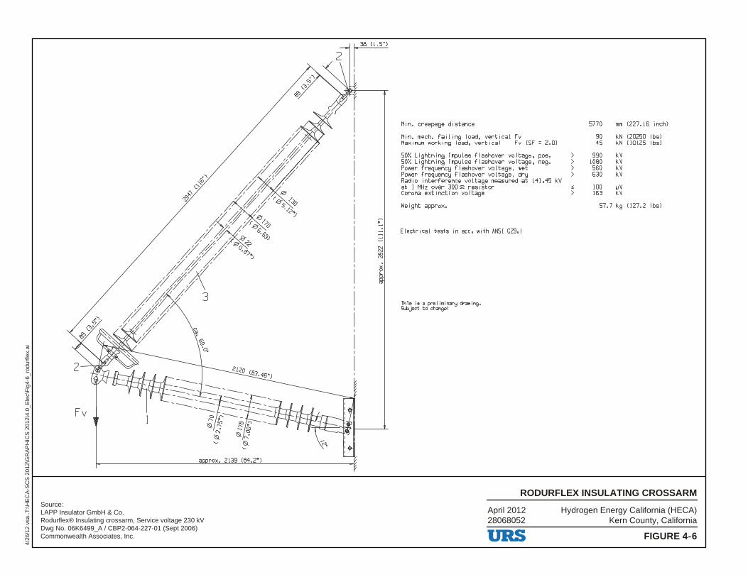
Source:LAPP Insulator GmbH & Co. Rodurflex® Insulating crossarm, Service voltage 230 kVDwg No. 06K6499_A / CBP2-064-227-01 (Sept 2006)Commonwealth Associates, Inc.
Hydrogen Energy California (HECA)Kern County, California
April 201228068052
FIGURE 4-6
RODURFLEX INSULATING CROSSARM
4/26
/12
vsa.
.T:\H
EC
A-S
CS
201
2\G
RA
PH
ICS
201
2\4.
0_E
lec\
Fig
4-6_
rodu
rfle
x.ai

8000
10000
12000
) lb
sV
MA
X V
ER
T L
OA
D (
FNote:BRACED LINE POST, 2.0 SF, Fv= WORKING LOAD
0
2000
4000
6000
-12000 -10000 -8000 -6000 -4000 -2000 0 2000 4000 6000 8000 10000 12000
) lbsTTRANSVERSE LOAD (FTENSION COMPRESSION
SAFE WORKING LOAD ISWITHIN THIS BOUNDARY
LIMIT OF FITTINGS
Source:LAPP Insulators, CBP2 -084-277-01Commonwealth Associates, Inc.
LIMIT OF FITTINGS
Post Limit (0 Long) Brace Limit
Minimum Load Connecting Hardware Limit
Longitudinal = 400 Longitudinal = 600
Longitudinal = 800
Hydrogen Energy California (HECA)Kern County, California
April 201228068052
FIGURE 4-7
COMBINED LOAD CHART
vsa/
hk_4
/26/
12...
U:\G
IS\H
EC
A\P
roje
cts\
HE
CA
_201
2\Ill
ustr
ator
_File
s\4.
0_E
lec
Tra
ns\F
ig4-
7_co
mbi
ned_
load
.ai
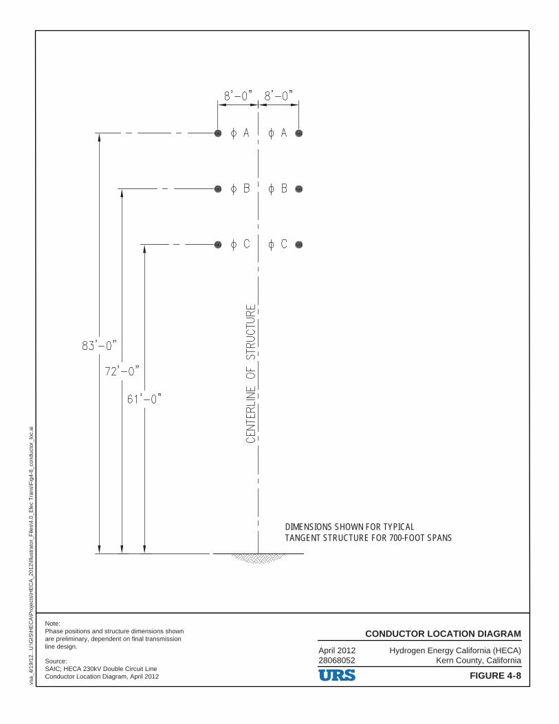
DIMENSIONS SHOWN FOR TYPICAL TANGENT STRUCTURE FOR 700-FOOT SPANS
Hydrogen Energy California (HECA)Kern County, California
April 201228068052
FIGURE 4-8
CONDUCTOR LOCATION DIAGRAM
vsa_
4/19
/12.
..U:\G
IS\H
EC
A\P
roje
cts\
HE
CA
_201
2\Ill
ustr
ator
_File
s\4.
0_E
lec
Tra
ns\F
ig4-
8_co
nduc
tor_
loc.
ai
Source:SAIC; HECA 230kV Double Circuit LineConductor Location Diagram, April 2012
Note:Phase positions and structure dimensions shown are preliminary, dependent on final transmission line design.
-60.
0
-56.
0
-52.
0
-48.
0
-44.
0
-40.
0
-36.
0
-32.
0
-28.
0
-24.
0
-20.
0
-16.
0
-12.
0
-8.0
-4.0 0.0
4.0
8.0
12.0
16.0
20.0
24.0
28.0
32.0
36.0
40.0
44.0
48.0
52.0
56.0
Au
dib
le N
ois
e (
dB
A)
Ra
in
Distance Across Right-of-Way (feet)
Audible Noise (dBA) L50 Rain
AN Both Circuits
AN One Circuit
42.0
43.0
44.0
45.0
46.0
47.0
48.0
49.0
Hydrogen Energy California (HECA)Kern County, California
April 201228068052
FIGURE 4-9
AUDIBLE NOISE
vsa_
4/19
/12.
..U:\G
IS\H
EC
A\P
roje
cts\
HE
CA
_201
2\Ill
ustr
ator
_File
s\4.
0_E
lec
Tra
ns\F
ig4-
9_au
dibl
e_no
ise.
ai

0
0.5
1
1.5
2
2.5
-60 -56 -52 -48 -44 -40 -36 -32 -28 -24 -20 -16 -12 -8 -4 0 4 8 12 16 20 24 28 32 36 40 44 48 52 56
Ele
ctri
c F
ield
(kV
/met
er)
Distance Across Right-of-Way (feet)
Electric Field (kV/meter)
Both Circuits
One Circuit
Hydrogen Energy California (HECA)Kern County, California
April 201228068052
FIGURE 4-10
ELECTRIC FIELD
vsa_
4/19
/12.
..U:\G
IS\H
EC
A\P
roje
cts\
HE
CA
_201
2\Ill
ustr
ator
_File
s\4.
0_E
lec
Tra
ns\F
ig4-
10_e
lect
ric_f
ield
.ai
0.00
5.00
10.00
15.00
20.00
25.00
30.00
35.00
40.00
-60.
0
-56.
0
-52.
0
-48.
0
-44.
0
-40.
0
-36.
0
-32.
0
-28.
0
-24.
0
-20.
0
-16.
0
-12.
0
-8.0
-4.0 0.0
4.0
8.0
12.0
16.0
20.0
24.0
28.0
32.0
36.0
40.0
44.0
48.0
52.0
56.0
Mag
net
ic F
lux
Den
sity
(m
G)
Distance Across Right-of-Way (feet)
Magnetic Flux Density B (mG)
Both Circuits
One CircuitHydrogen Energy California (HECA)
Kern County, CaliforniaApril 201228068052
FIGURE 4-11
MAGENTIC FIELD
vsa_
4/19
/12.
..U:\G
IS\H
EC
A\P
roje
cts\
HE
CA
_201
2\Ill
ustr
ator
_File
s\4.
0_E
lec
Tra
ns\F
ig4-
11_m
agne
tic_f
ield
.ai

0.0
10.0
20.0
30.0
40.0
50.0
60.0
70.0
-60.
0
-56.
0
-52.
0
-48.
0
-44.
0
-40.
0
-36.
0
-32.
0
-28.
0
-24.
0
-20.
0
-16.
0
-12.
0
-8.0
-4.0 0.0
4.0
8.0
12.0
16.0
20.0
24.0
28.0
32.0
36.0
40.0
44.0
48.0
52.0
56.0
Ra
dio
In
flu
en
ce
(d
B m
icro
volt
s p
er
me
ter)
Distance Across Right-of-Way (feet)
Radio Influence Voltage [Interference] at 1 MHz, RAIN
Both Circuits
One Circuit Hydrogen Energy California (HECA)Kern County, California
April 201228068052
FIGURE 4-12
RADIO INFLUENCE
vsa_
4/19
/12.
..U:\G
IS\H
EC
A\P
roje
cts\
HE
CA
_201
2\Ill
ustr
ator
_File
s\4.
0_E
lec
Tra
ns\F
ig4-
12_r
adio
.ai