
4-DESIGN AND TESTING OF THE 210 MW AIR
17
DESIGN AND TESTING OF THE 210 MW AIR-COOLED SERIAL TURBOGENERATOR FOR THE JYVASKYLA CHP IN FINLAND N.Pinchuk, O.Antonuk, M.Roytgarts INTRODUCTION Air-cooled turbogenerators are distinguished by high reliability, explosion safety, easy and convenient in operation. In view of increasing demand, a new series of air-cooled turbogenerators for steam and gas turbines, having the common design solutions and similar- type ventilation system [1], was developed at the Branch Electrosila of the OJSC Power Machines in St. Petersburg. By the present moment about 60 turbogenerators of this series have been manufactured and under successful operation at sites both in Russia and abroad. The air-cooled turbogenerators of 100 MVA and 200 MVA output have been supplied for steam and gas turbines in Hungary, Croatia, Iraq, Kazakhstan and other countries of the world. Type Т3ФП-220-2У3 turbogenerator with the rated output of 233 MVA for the Jyvaskyla Project (Finland) was manufactured on the bases of the series 265 MVA turbogenerator to suit the requirements of the Contract. Main contractual requirements Rated output 233.3 MVA (guaranteed) Rated power factor 0.90 Rated voltage 15.75 kV Rated frequency 50 Hz Rated secondary coolant temperature 25°C Efficiency, no minus tolerance 98.7% (guaranteed) Brushless exciter Indirect air-cooling of stator winding Direct air-cooling of rotor winding The winding insulation thermal classification 155(F) The insulation temperature under the rated conditions 130(B) The bearing vibrations measured in three mutually perpendicular directions shall comply with zone A (3.8 mm/s) of ISO 10816-2 (guaranteed value).
Transcript of 4-DESIGN AND TESTING OF THE 210 MW AIR

DESIGN AND TESTING OF THE 210 MW AIR-COOLED SERIAL
TURBOGENERATOR FOR THE JYVASKYLA CHP IN FINLAND
N.Pinchuk, O.Antonuk, M.Roytgarts
INTRODUCTION
Air-cooled turbogenerators are distinguished by high reliability, explosion safety, easy
and convenient in operation. In view of increasing demand, a new series of air-cooled
turbogenerators for steam and gas turbines, having the common design solutions and similar-
type ventilation system [1], was developed at the Branch Electrosila of the OJSC Power
Machines in St. Petersburg. By the present moment about 60 turbogenerators of this series
have been manufactured and under successful operation at sites both in Russia and abroad.
The air-cooled turbogenerators of 100 MVA and 200 MVA output have been supplied for
steam and gas turbines in Hungary, Croatia, Iraq, Kazakhstan and other countries of the
world.
Type Т3ФП-220-2У3 turbogenerator with the rated output of 233 MVA for the
Jyvaskyla Project (Finland) was manufactured on the bases of the series 265 MVA
turbogenerator to suit the requirements of the Contract.
Main contractual requirements
Rated output 233.3 MVA (guaranteed)
Rated power factor 0.90
Rated voltage 15.75 kV
Rated frequency 50 Hz
Rated secondary coolant temperature 25°C
Efficiency, no minus tolerance 98.7% (guaranteed)
Brushless exciter
Indirect air-cooling of stator winding
Direct air-cooling of rotor winding
The winding insulation thermal classification 155(F)
The insulation temperature under the rated conditions 130(B)
The bearing vibrations measured in three mutually perpendicular directions shall
comply with zone A (3.8 mm/s) of ISO 10816-2 (guaranteed value).

The shaft vibrations shall comply with the zone A (80 micron) of ISO 7919-2
(guaranteed value).
The average noise pressure level measured at a distance of 1 m from the generator
surface shall not exceed 82 dB(A) according to ISO 3746 (guaranty).
Generator shall comply with IEC Standards, EC Directives and official regulations and
requirements of authorities valid in Finland at the time of the take-over.
The guarantee excluding electronic components of exciter shall be valid four years
from the take-over.
These rather strict requirements were taken into account when manufacturing the
above-mentioned turbogenerator (Fig. 1).
Fig. 1. Type Т3ФП-220-2У3 turbogenerator at the manufacturing plant test rig
TURBOGENERATOR DESIGN FEATURES
STATOR WINDING AND CORE
In the series air-cooled type Т3ФП-220-2У3 turbogenerator the use was made of the
conventional double-layer bar-type winding with transposition of strands both in the slot part
and in the end-winding part in order to reduce the stray-load losses. Upper and lower bars
have different number of strands in order to equalize the specific losses along the bar height.
The stator winding high-voltage insulation quality is of fundamental importance. The
use of dry thin insulation for bars with subsequent vacuum-pressure impregnation of the stator
complete with the winding as per the Global VPI technology (Fig. 2) reduced the labour
input, permitted to reduce the temperature drop in the insulation thickness and to increase the

specific current load with the assurance of heating the class F insulation as per class B. During
the vacuum-pressure impregnation of the stator complete with the winding, the clearances
between the winding and the stator core steel are filled with compound, the insulation thermal
conductivity is improved and the stator rigidity relative to bending vibrations under the action
of radial electromagnetic forces is increased.
Fig. 2. Stator before the vacuum-pressure impregnation
In order to decrease the losses and heating as well as to improve the reliability of
turbogenerator stator end zone, the direction of winding the stator (arrangement of the leading
and lagging layers of the double-layer winding) was chosen based on the numerical modelling
with due account of the field rotation direction [2].
The cold-rolled electric steel with decreased magnetic losses was used in order to
reduce the stator core losses. When fastening the core onto the dovetail bars, the end packs
were insulated against the fastening dovetail bars in order to limit the ways of eddy current
flowing into the end packs. The flexible copper links were used to close the eddy currents
induced by the magnetic stray field of the stator core in the fastening dovetail bars. The
copper links reduce the stray-load losses and the heating of the end packs and pressure plates
of the turbogenerator stator core.
ROTOR WINDING AND SHAFT
To manufacture the rotor the use was made of high-strength steel forging with alloy
additions. The rotor winding was laid in the rectangular slots. The direct cooled rotor design
is shown in Fig. 3.

Fig. 3. Rotor of the air-cooled turbogenerator
When laying the winding into the rotor slots, the technology of high-frequency
induction brazing of half-turns was used. The rotor multi turn coil winding distribution in
slots was chosen from the condition of achieving the best shape of the field, with which the
excitation magnetic field is of the maximum use to create the first voltage harmonic at the
turbogenerator terminals. In the process of designing both the basic losses in the field winding
and the excitation-field harmonic stray-load losses on the stator surface were minimized.
In order to eliminate the unequal rotor rigidity in the longitudinal axis and the
transverse axis, which causes the rotor vibration at the double speed of rotation, longitudinal
slots on the big tooth of each pole were made in the rotor body. The dimensions and the
number of these slots were chosen so that the main moments of the rotor inertia would have
been equalized. The equalizing slots were filled with a magnetic material with cloth-based
laminate gaskets. When the rotor is rotating, the longitudinal forces acting on the filler
material are reduced due to a shearing strain, and the filler material does not make the rotor
body more rigid. The filler material is held in the equalizing slots by means of wedges, which
are a part of a complete rotor damping system. The system of equalizing the unequal rigidity
provides the ultimate lower vibration level of the rotor and bearings with the double speed of
rotation.
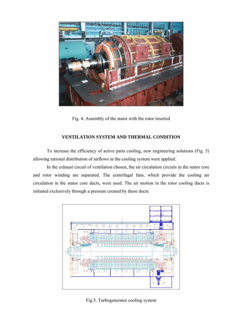
Fig. 4. Assembly of the stator with the rotor inserted
VENTILATION SYSTEM AND THERMAL CONDITION
To increase the efficiency of active parts cooling, new engineering solutions (Fig. 5)
allowing rational distribution of airflows in the cooling system were applied.
In the exhaust circuit of ventilation chosen, the air circulation circuits in the stator core
and rotor winding are separated. The centrifugal fans, which provide the cooling air
circulation in the stator core ducts, were used. The air motion in the rotor cooling ducts is
initiated exclusively through a pressure created by these ducts.
Fig.5. Turbogenerator cooling system

Fig.6. Turbogenerator rotor and stator ventilation
As in many world large companies, for cooling of the rotor winding the radial ducts
are used for the slot portion and the axial ducts are used for the end windings. The radial ducts
are provided with cooling air by means of under-slot ducts.
The main advantage of this ventilation system is the uniform gas supply to the stator
core ducts and, as a consequence, the practically uniform distribution of the winding and
active steel temperatures along the circumference and along the stator length.
As shown by the tests performed under operational conditions of various
turbogenerators of the series considered, the difference of the maximum measured
temperature from the average value for the active steel does not exceed a value of 5°-7°C.
Practically uniform temperature distribution in the stator was achieved due to the fact
that the losses generated in the slot portion were removed by the system of U-shaped ducts,
which do not communicate with the air gap between the stator and rotor. The system of U-
shaped ducts is shown in Fig. 6. In the design with U-shaped ducts, cold air from a discharge
chamber located at the stator periphery reaches the radial ducts between the active steel packs
and successively passes first towards the bore, then comes back in the opposite direction
towards the rarefaction chambers, also located at the stator periphery.
The type Т3ФП-220-2У3 turbogenerator design was updated with due account of the
contract required rated power decrease with respect to the series turbogenerator output as well
as of the requirements to the efficiency value. The ventilation and mechanical losses for the

air-cooled turbogenerators amount to about 40% of the total losses [1]. To ensure the
efficiency guarantee value the mechanical losses are decreased through the reduction of the
cooling airflow through the rotor and stator. By using the centrifugal fan of lower capacity the
airflow through the stator is decreased, by changing the cross-section of the rotor under-slot
cooling ducts the airflow through the rotor is also decreased. In doing so, the ventilation
system efficiency was proved by calculations.
NOISE-PROTECTION ENCLOSURE
The special feature of the turbogenerator noise-protection enclosure is that it is also
the housing, along the inner surface of which the cooling air flows at a high speed. The results
of the experimental studies on the turbogenerator noise level and spectral composition showed
that the generator internal noise is of the broadband nature and the noise level amounts to
about 116 dBA. To meet the contract requirements, the noise had to be decreased by 34 dB,
that is the value had to be 50 times less. For this purpose the high-effective noise- protection
composite materials were chosen and the acoustically closed enclosure was manufactured.
Taken into account was that the enclosure design efficiency was less that the efficiency of the
materials used. The through metal elements of the structure and slits are the sound conductors
that lead to the generation of secondary sound sources on the enclosure surface, which
substantially decrease the noise protection efficiency. The noise- protection enclosure
structure covers the turbogenerator itself, the brushless exciter and bearings as well as the
neutral terminals box, the housing of which is made of aluminium in order to meet the
electromagnetic compatibility requirements (Fig. 1).
RESULTS OF FINAL FACTORY RIG TESTS
The generator with exciter and synchronous motor were assembled and balanced for
the carrying out the final factory tests.
When analyzing the test results, let us limit ourselves with the check of meeting the
most important operational guarantees.
LOSSES AND EFFICIENCY
According to the contract the turbogenerator guaranteed efficiency at the rated
parameters without negative tolerance shall amount to at least 98.7%.

When testing the generator at the manufacturing plant test rig, the efficiency η is
determined by using the indirect method of separated losses by the following formula:
( )[ ] %,PP/P1100 2∑ ∑+−⋅=η (1)
where 2P and ∑P are the active power and the sum of losses in the turbogenerator
respectively, kW
The sum of losses is determined by the following equation:
∑ +++= fscfemech PPPPP (2)
where:
mechP are the mechanical losses, kW;
feP are the stator active steel losses, kW;
scP are the short-circuit losses, kW;
fP are the excitation losses, kW.
The losses Pmech, Pfe and Psc are determined simultaneously with the determination of
the no-load and short-circuit characteristics. When taking the readings of each point of
characteristics of the generator under test, the measurements of power P1 consumed by the
drive motor as well as of the current and voltage at the motor terminals are taken. The above-
mentioned measurements permit to determine the motor losses ΣРmot based on the earlier
performed calibration results.
The losses of the generator under test are determined as a difference between the
consumable power by the drive motor and the losses of the motor itself.
∑−= mot1gen PPP (3)
The generator mechanical losses Pmech are determined as the averaged losses obtained
in the no-load and short-circuit tests in points U = 0 and I = 0. In this case the generator and
motor total mechanical losses are taken to calculate the efficiency.
The excitation losses are determined by the following formula:
ex75f2
ff PRIP +⋅= (4)
where: If is the turbogenerator excitation current at the rated load conditions (design value) А;

Rf is the rotor winding resistance (measured value) reduced to the design operating
temperature, Ohm;
Рex are the exciter losses (without the mechanical ones) when loaded with rotor rated
current If, reduced to the design operating temperature, kW.
Results of the losses determination are shown in Table 1.
Table 1. Turbogenerator losses and efficiency
Description Designation Value
Mechanical losses, kW Pmech 1216
Active steel losses, kW Pfe 362
Short-circuit losses, kW Psc 634
Excitation losses, kW Pf 407
Total losses, kW ΣP 2619
Efficiency, % η 98.77
The values included in formula (1) are determined with some uncertainty, which shall
be taken into consideration in the final result. For the quantitative evaluation of the
measurements accuracy it is expedient to point out the dependence of the efficiency indirect
measurement results upon the uncertainty of the separated losses determination (truncation
error). Absolute error of the efficiency values measured is expressed by the following
formula:
( ) 100/P)100/1( ∑⋅−⋅= δηηη∆ , % (5)
Therein ∑Pδ is the relative error of the separated losses sum determining, in percent.
Shown in Fig. 7 are the curves of the efficiency determination absolute error versus both
the efficiency value measured and the losses sum determination error.
From formula (5) and Fig. 7 it follows that, for example, in case the losses
determination error is 1%, the generator efficiency value measured being up to 99% has no
more than three true significant digits.

The separated losses determination error in its turn depends upon the procedure and the
uncertainty of these losses measurements. The separated losses determination errors have the
practically normal law of distribution; the error confidence limits, with the specified
probability within which is the error, are used for their calculation.
Taking into account the truncation error for the method of separated losses the generator
efficiency value is determined by the following formula:
( )[ ]100/P)100/1(1t ∑⋅−±⋅=±= δηηη∆ηη (6)
With due account of the measurements uncertainty the efficiency of the tested
turbogenerator was equal to 98.77±0.05%, which value for sure corresponded to the contract
requirements. The record of the efficiency measured value without showing the uncertainty
would have meant that the efficiency determination uncertainty did not exceed the one half of
unit of the value the last digit. As per formula (5) the uncertainty of the separate losses sum
determination in this case shall be no less than 0.4%, which is practically unachievable.
Fig. 7. Truncation error of the efficiency determination using the indirect method

HEAT RUN TEST
Temperatures of the structural parts were measured by means of the standard
temperature monitoring system, i.e. RTDs.
The stator winding and active steel temperature rise was determined by the following
formula:
noexnlshc ∆Θ∆Θ∆Θ∆Θ −+= , (7)
where noexnlshc ,, ∆Θ∆Θ∆Θ are the temperature rises under the following conditions: short-
circuit conditions with the rated current in the stator winding, no-load conditions with the
stator rated voltage and no-load conditions without excitation, respectively.
The rotor winding temperature was determined by the resistance value, the use was
made of the exciter load characteristics and the results of the exciter excitation voltage and
current measurements under the no-load and short-circuit conditions. Under the no-load
conditions without excitation the measuring current was supplied to the slip rings from the
external power source. The rotor winding temperature rises were obtained by extrapolating
the temperature rise values in relation to the losses in the winding.
Table 2. Temperature rises and generator heating
Stator winding Stator active steel Rotor winding Operating
conditions Temperature rise, ºC
Heating, ºC
Temperature rise, ºC
Heating, ºC
Temperature rise, ºC
Heating, ºC
Without excitation 6 38 4 36 14 46
No-load 26 58 17 49 17 49 Short-circuit 42 74 20 52 37 69
Rated load 62 94 33 65 70 102
As shown in the table, the main generator active assemblies have the heating margin
corresponding to 10% of increase in power. The heating margin improves the generator
operational reliability.
To meet the contract requirement, the neutral terminals box is of closed design, thus
excluding the heat exchange with the surrounding space. In this connection the maximum
temperature of neutral terminals plate (six points) and that of the current transformer surface

(six points) was measured under the steady-state thermal conditions by using the temperature-
indicating tags. These measurements showed that under the sustained short-circuit conditions
with the stator rated current and at a cold air temperature downstream the air coolers of 32°C,
the maximum temperature of the clamping plate is 75ºC, while the temperature of the current
transformer surface is 59ºC. Thus, during the generator operation no overheating occurs in the
neutral terminals box.
VIBRATION DETERMINATION
In the course of the factory tests the vibration velocity spectrum components were
measured in three mutually perpendicular directions in the frequency band of 10…500 Hz.
The root-mean-square value of the vibration velocity shall be no more than 3.8 mm/s. The
shaft vibration double (peak-to-peak) amplitude shall be no more than 80 µm.
The results of the vibration measurements taken at the test rig are shown in Table 3.
Table 3. Bearing vibration, mm/s, and shaft vibration, micron
Bearing, turbine side Bearing, exciter side Operating conditions Vertical Transverse Axial Vertical Transverse Axial
Shaft vibration
Without excitation 1.3 1.7 3.5 1.8 0.7 2.6 53
No-load U=Urated
1.4 1.8 3.5 2.1 0.9 3.2 53
Short-circuit I=Irated
1.3 2.1 3.7 2.5 1.0 3.4 53
The low levels of vibration are provided by:
- removing the rotor shaft and bearing natural frequencies in excess of 15% of the
rotational speed (the first critical frequency is at 940 rpm, while the second one is at 2430
rpm);
- highly accurate rotor balancing, the generating unit assembling and vibration
adjustment at the test rig.
TURBOGENERATOR NOISE
In accordance with the contract the average level of sound pressure created by the
generator and exciter at the power plant shall not exceed 82 bB(A) when the measurements
are taken at a distance of 1 m from the generator housing as per ISO 3746.
The noise measurements were conducted at the manufacturing plant test rig with the
generator operating under the motor mode without load at the rated speed of rotation and the
rated stator voltage. The measurement points were located around the generator at a distance
of 1 m from the generator surface. In each point the sound level and the noise pressure levels
were determined in 1/3 of octave-frequency band being within 50 to 10000 Hz. 49 points
were used to measure the air noise. The measurements were conducted using the precision
instrumentation of Bruel&Kjaer Company made.
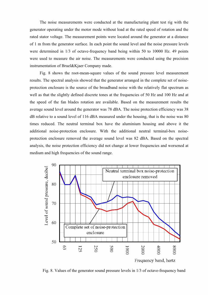
Fig. 8 shows the root-mean-square values of the sound pressure level measurement
results. The spectral analysis showed that the generator arranged in the complete set of noise-
protection enclosure is the source of the broadband noise with the relatively flat spectrum as
well as that the slightly defined discrete tones at the frequencies of 50 Hz and 100 Hz and at
the speed of the fan blades rotation are available. Based on the measurement results the
average sound level around the generator was 78 dBA. The noise protection efficiency was 38
dB relative to a sound level of 116 dBA measured under the housing, that is the noise was 80
times reduced. The neutral terminal box have the aluminium housing and above it the
additional noise-protection enclosure. With the additional neutral terminal-box noise-
protection enclosure removed the average sound level was 82 dBA. Based on the spectral
analysis, the noise protection efficiency did not change at lower frequencies and worsened at
medium and high frequencies of the sound range.
Fig. 8. Values of the generator sound pressure levels in 1/3 of octave-frequency band

The study of the test rig acoustical conditions showed that the results reproducibility has
the root-mean-square deviation less than 3 dB. Hence it follows that at a confidence
probability of 90% the noise level measurement uncertainty is within ± 4 dB.
Thus the measured noise of the turbogenerator arranged in the noise-protection
enclosure with a probability of 90% does not exceed 82 dB(A).
TESTS ON INSULATION OF THE STATOR WINDING BARS
The tests on insulation of two stator winding bars were conducted in accordance with
European Standard EN 50209 at a specially manufactured slot test mock-up prior to the
winding laying into the stator slots. The Standard requirements cover the insulation made of
preliminarily impregnated tapes as well as the insulation obtained by applying the vacuum-
pressure impregnation method.
The first step of the test is the measurement of the dielectric loss tangent.
The voltage varied from 0.2 to 1 Urated with an increment of 0.2 Urated. The
measurements were conducted in the initial conditions and after heating up to 90°C with
subsequent cooling to an ambient temperature.
As the evaluation criteria the use was made of the maximum value of the ∆tgδ change
for the measured interval of 0.2Urated before and after the sample heating. The results of
measurements before and after heating shall not differ by more than 0.2% and shall not be
more than 0.7%. Results of measurements are shown in Table 4.
Table 4. Loss tangent change during the tests
,%tgδ∆
Test sample 1 Test sample 2 Range of change
In the initial conditions
After heating up to 90ºC and subsequent
cooling
In the initial conditions
After heating up to 90ºC and subsequent
cooling 2.04.0 tgtg δδ − 0.025 0.010 0.004 0.012
4.06.0 tgtg δδ − 0.040 0.010 0.009 0.004
6.08.0 tgtg δδ − 0.046 0.030 0.006 0.006
8.00.1 tgtg δδ − 0.024 0.011 0.004 0.003
0.5( )tgtg 2.06.0 δδ − 0.033 0.010 0.007 0.008

Then the bars withstood the overvoltage tests with a voltage of 32.5 kV, 50 Hz, applied
for 1 min. With the voltage being raised up to 70 kV, no breakdown or flashover occurred.
Thereby the insulation quality and compliance with Standard EN 50209 requirements were
proved.
After completing the rig tests the final high-voltage dielectric strength tests on the stator
winding were conducted with a voltage of 32.5 kV, 50 Hz, applied for 1 min. The tests were
conducted for each phase with other phases being shorted to the ground housing. The
generator has successfully withstood these tests.
CONCLUSION
The factory rig tests of the air-cooled type Т3ФП-220-2 turbogenerator manufactured
for Jyvaskyla TPP showed the complete compliance with European standards, norms and
contract requirements imposed on the guaranteed technical parameters, including the rated
output, efficiency and heating levels of the main assemblies, winding insulation durability,
noise and vibration levels, etc. The factory tests analysing was made taking into account not
only of the directly measured values but of the methodological and statistical uncertainty of
measurements.
At the present time the Т3ФП-220-2 turbogenerator is erected at the power plant in
Finland and is under the complex of the commissioning tests being a part of the power-
generating unit.
The demand for high-reliable and easy-to-operate turbogenerators directs the design
and research works for the further increase in the unit power of air-cooled turbogenerators,
which corresponds to the tendencies of the world electric machine industry development.
REFERENCES
1. O.Antonyuk, T.Kartashova, M.Roytgarts. Series of air-cooled turbogenerators of
power up to 410 MVA. Intetnational Conference POWER-GEN Europe 2009, 26-29 May
2009, Cologne, Germany.
2. M.Roytgarts, Yu.Varlamov, A.Smirnov. Electromagnetic computation in the end
zone of loaded turbogenerator. ADVANCED COMPUTER TECHNIQUES IN APPLIED
ELECTROMAGNETICS/ Springer, 2008, IOS PRESS. Chapter C. Applications/
C1.Electrical Machines and Transformers.
3. Y.Samorodov. Defects of generators, M, 2005, 350 p. (In Russian)
APPLICATION
FOREIGN OBJECTS PENETRATION INSIDE THE TURBOGENERATOR
It is well known that the penetration of foreign objects inside the turbogenerator is
impermissible and may result in severe accidents and emergency [3].
The procedure of calculating the electromagnetic fields in the end zone, which was
developed at Branch Electrosila, permitted to perform the numerical simulation of possible
emergency with stator winding damage due to the foreign objects getting inside the
turbogenerator. Figs 9 and 10 show the model for the numerical analysis and the results of
calculating the electromagnetic field in the turbogenerator end zone at the rated stator winding
current [2].
Fig.9. Numerical simulation of the turbogenerator end zone
Fig.10. Results of calculating the electromagnetic field
a) b)
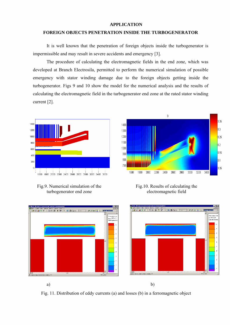
Fig. 11. Distribution of eddy currents (a) and losses (b) in a ferromagnetic object

Fig.12. Ferromagnetic object heating on the stator-winding surface
When the foreign object gets on the stator winding end portions, the eddy currents are
induced in this object under the action of the turbogenerator three-dimensional electromagnetic
field (Fig. 11a) and the losses are generated (Fig. 11b). In case the object is of magnetic steel, the
eddy currents have the drastically non-uniform distribution along the object. These eddy currents
are displaced to the surface and flow in the layer with a thickness equal to the depth of the field
penetration. For magnetic steel this value is 1.3 mm. The value of the losses generated in the
object are the quadratic function of the magnetic flux density, therefore these losses are
generated in even much thinner layer of the steel object (Fig. 11b).
The heating is determined based on the obtained distribution of losses in the object
volume, taking into account the cooling conditions (Fig. 12). According to the calculation results
the steel object temperature on the bar insulation surface reaches 700ºC, that is more than enough
for the bar ground and turn-to-turn insulation destruction. Thus, the ferromagnetic object getting
inside the turbogenerator inevitably leads to the emergency situation in the turbogenerator.