4 BBL THROTTLE BODY FUEL INJECTION SYSTEM · PDF file4 BBL THROTTLE BODY FUEL INJECTION SYSTEM...
54
1 4 BBL THROTTLE BODY FUEL INJECTION SYSTEM WITH TRANSMISSION CONTROL 550-407 950 CFM 200-600 HP Polished Aluminum 550-408 950 CFM 200-600 HP Hard Core Gray™ INSTALLATION MANUAL – 199R10772 NOTE: These instructions must be read and fully understood before beginning installation. If this manual is not fully understood, installation should not be attempted. Failure to follow these instructions, including the pictures may result in subsequent system failure. NOTE: Fits all standard square flange and most aftermarket universal flanged spread bore intake manifolds.
Transcript of 4 BBL THROTTLE BODY FUEL INJECTION SYSTEM · PDF file4 BBL THROTTLE BODY FUEL INJECTION SYSTEM...

1
4 BBL THROTTLE BODY
FUEL INJECTION SYSTEM WITH TRANSMISSION CONTROL
550-407 950 CFM 200-600 HP Polished Aluminum
550-408 950 CFM 200-600 HP Hard Core Gray™
INSTALLATION MANUAL – 199R10772
NOTE: These instructions must be read and fully understood before beginning installation. If this manual is not fully
understood, installation should not be attempted. Failure to follow these instructions, including the pictures may
result in subsequent system failure.
NOTE: Fits all standard square flange and most aftermarket universal flanged spread bore intake manifolds.

2
TABLE OF CONTENTS: 1.0 INTRODUCTION ...................................................................................................................................................................... 3 2.0 WARNINGS, NOTES, AND NOTICES ..................................................................................................................................... 3 3.0 PARTS IDENTIFICATION ........................................................................................................................................................ 4 4.0 ADDITIONAL ITEMS REQUIRED FOR INSTALLATION ......................................................................................................... 5 5.0 TOOLS REQUIRED FOR INSTALLATION .............................................................................................................................. 6 6.0 COOLANT TEMPERATURE SENSOR INSTALLATION .......................................................................................................... 6 7.0 REMOVAL OF EXISTING COMPONENTS .............................................................................................................................. 6 8.0 TERMINATOR™ EFI TBI SYSTEM INSTALLATION ............................................................................................................... 6
8.1 Throttle Body ........................................................................................................................................................................ 6 8.2 Throttle Connections ............................................................................................................................................................ 7 8.3 MAP Sensor Installation and Vacuum Line Connections ..................................................................................................... 8 8.4 Fuel Pump, Fuel Line, and Filter Installation ........................................................................................................................ 8 8.5 Oxygen Sensor Installation................................................................................................................................................... 8
8.5.1 Oxygen Sensor Mounting Procedure ............................................................................................................................. 9 8.6 ECU Mounting ...................................................................................................................................................................... 9
9.0 WIRING .................................................................................................................................................................................. 10 9.1 Important Wiring “Do’s and Don’ts” .................................................................................................................................... 10
10.0 WIRING HARNESS INSTALLATION ................................................................................................................................... 10 10.1 Main Power/Battery Connection ....................................................................................................................................... 10
11.0 PRIMARY HARNESS INSTALLATION AND SENSOR CONNECTIONS............................................................................. 10 11.1 ECU Connectors .............................................................................................................................................................. 11 11.2 Harness Routing ............................................................................................................................................................... 11 11.3 Sensor Connections & Outputs ........................................................................................................................................ 12
11.3.1 Throttle Body Bulkhead Connector (Bulkhead) .......................................................................................................... 12 11.3.2 Coolant Temperature Sensor (CTS) .......................................................................................................................... 12 11.3.3 Wide Band Oxygen Sensor (WB02) .......................................................................................................................... 12 11.3.4 Fuel Pressure (Fuel) .................................................................................................................................................. 12 11.3.5 CANbus – Handheld (CAN) ....................................................................................................................................... 13 11.3.6 Ignition (IGN) .............................................................................................................................................................. 13
12.0 LOOSE WIRES .................................................................................................................................................................... 13 13.0 IGNITION/ENGINE SPEED INPUT ...................................................................................................................................... 14
13.1 Ignition/Engine Speed Input Wiring .................................................................................................................................. 15 14.0 ADDITIONAL OUTPUTS ...................................................................................................................................................... 19
14.1 Transmission Wiring ......................................................................................................................................................... 19 APPENDIX 1.0 PINOUT ................................................................................................................................................................ 21 15.0 PREVIOUS INSTALLATION REQUIRED............................................................................................................................. 21 16.0 TERMINATOR™ INSTRUCTIONS AND TUNING ............................................................................................................... 21 17.0 INITIAL POWER-UP ............................................................................................................................................................ 22 18.0 HANDHELD NAVIGATION & USE ....................................................................................................................................... 22
18.1 Making Adjustments .......................................................................................................................................................... 22 19.0 HOME SCREEN ................................................................................................................................................................... 23 20.0 CALIBRATION WIZARD ...................................................................................................................................................... 24 21.0 TPS AUTOSET .................................................................................................................................................................... 26 22.0 TRANSMISSION SETUP ..................................................................................................................................................... 27
22.1 Transmission .................................................................................................................................................................... 27 22.1.1 Trans Setup ............................................................................................................................................................... 27 22.1.2 Speed Calc ................................................................................................................................................................ 28
23.0 SENSOR VERIFICATION .................................................................................................................................................... 28 24.0 STARTUP............................................................................................................................................................................. 29 25.0 SETTING IGNITION TIMING................................................................................................................................................ 29 26.0 AFTER-STARTUP ................................................................................................................................................................ 29 27.0 IDLE SETTING/THROTTLE PLATE SETTING .................................................................................................................... 29 28.0 SELF-TUNING ..................................................................................................................................................................... 30 29.0 GAUGE SCREENS .............................................................................................................................................................. 31
29.1 Monitor ............................................................................................................................................................................. 31 29.1.1 Multi-Gauge ............................................................................................................................................................... 31 29.1.2 Monitors ..................................................................................................................................................................... 32 29.1.3 Diagnostics ................................................................................................................................................................ 32
30.0 Custom Setups..................................................................................................................................................................... 32 30.1 Dash Setup ....................................................................................................................................................................... 32 30.2 Channels Scaling ............................................................................................................................................................. 33
31.0 FILE SAVING/LOADING ...................................................................................................................................................... 33 31.1 File ..................................................................................................................................................................................... 33
31.1.1 ECU Overview ............................................................................................................................................................ 34 31.1.2 ECU Globals .............................................................................................................................................................. 34 31.1.3 ECU Data Logging ..................................................................................................................................................... 35 31.1.4 ECU Hardware/Firmware (HW/FW) ........................................................................................................................... 35 31.1.5 Local Setup ................................................................................................................................................................ 36

3
32.0 BASIC TUNING .................................................................................................................................................................... 36 32.1 Basic Fuel ......................................................................................................................................................................... 37
32.1.1 Target AFR ................................................................................................................................................................ 37 32.1.2 Acceleration Enrichment ............................................................................................................................................ 38 32.1.3 Fuel Prime .................................................................................................................................................................. 38
32.2 Fuel Learn ........................................................................................................................................................................ 39 32.2.1 Learn Enable/Disable ................................................................................................................................................. 39 32.2.2 Learn Speed .............................................................................................................................................................. 39
32.3 Basic Idle .......................................................................................................................................................................... 39 32.4 Spark ................................................................................................................................................................................ 40 32.5 Transmission ..................................................................................................................................................................... 40
32.5.1 Shifts .......................................................................................................................................................................... 40 32.5.2 WOT Shifts ................................................................................................................................................................ 41 32.5.3 Torque Converter Clutch (TCC) Parameters ............................................................................................................. 42 32.5.4 Torque Converter Clutch (TCC) (Un) Lock ................................................................................................................ 42 32.5.5 Line Pressure ............................................................................................................................................................. 43
33.0 SYSTEM SETUP .................................................................................................................................................................. 43 33.1 System Tuning ................................................................................................................................................................. 43
33.1.1 Outputs ...................................................................................................................................................................... 44 33.1.2 Engine Setup ............................................................................................................................................................. 44 33.1.3 Ignition Setup ............................................................................................................................................................. 45
34.0 ADVANCED TUNING ........................................................................................................................................................... 46 34.1 Advanced Fuel ................................................................................................................................................................. 46 34.2 Closed Loop ..................................................................................................................................................................... 46 34.3 Advanced Learn ............................................................................................................................................................... 47 34.3 Advanced Idle ................................................................................................................................................................... 48
34.3.1 IAC Rampdown .......................................................................................................................................................... 48 34.3.2 IAC Speed .................................................................................................................................................................. 49 34.3.3 IAC Startup ................................................................................................................................................................ 49 34.3.4 Idle Spark ................................................................................................................................................................... 50
APPENDIX 2.0 SENSOR DIAGNOSTICS AND STATUSES ........................................................................................................ 51
1.0 INTRODUCTION Holley Performance Products has written this manual for the installation of the TERMINATOR™ EFI TBI fuel injection system. This manual contains the information necessary for the installation of the hardware contained in this kit, which includes the ECU, wiring, throttle body, and sensors. It also contains all tuning information. This instruction sheet does not include installation instructions for the fuel
system (pump, filters, regulators and lines). Please read all the WARNINGS and NOTES, as they contain valuable information that can save you time and money. It is our intent to provide the best possible products for our customer; products that perform properly and satisfy your expectations. Should you need information or parts assistance, please contact our technical service department at 1-270-781-9741, Monday through Friday, 8 a.m. to 5 p.m. Central Time. By using this number, you may obtain any information and/or parts assistance that you may require. Please have the part number of the product you purchased when you call.
2.0 WARNINGS, NOTES, AND NOTICES
NOTE: This system does not contain fuel system components that are required including the fuel pump, fuel filters, fuel
pressure regulator, and lines. These kits can be purchased separately (526-1, 526-2, 526-3, & 526-4).
NOTE: This system is designed for naturally aspirated V8 engines between 250 – 600 HP.
WARNING! The TERMINATOR™ EFI systems consist of a number of sophisticated components. Failure of any one component
does not constitute, nor does it justify, warranty of the complete system. Individual service items are available for
replacement of components. If assistance is required or if you need further warranty clarification, you can call
Holley Technical Service at the number shown above.
WARNING! To preserve warranty, these instructions must be read and followed thoroughly and completely before and during
installation. It is important that you become familiar with the parts and the installation of the TERMINATOR™ EFI
system before you begin. Failure to read and understand these instructions could result in damage to
TERMINATOR™ EFI components that are not covered by the warranty and could result in serious personal injury
and property damage.
WARNING! The oxygen sensor in this kit is recommended for use with ONLY unleaded fuel. Use of leaded fuels will degrade
the oxygen sensor and will result in incorrect exhaust gas oxygen readings and improper fuel delivery. Failure to
follow these directions does not constitute the right to a warranty claim.
4
WARNING! Failure to follow all of the above will result in an improper installation, which may lead to personal injury, including
death, and/or property damage. Improper installation and/or use of this or any Holley product will void all
warranties.
WARNING! Use of some RTV silicone sealers will destroy the oxygen sensor used with this product. Ensure the RTV silicone
sealant you use is compatible with oxygen sensor vehicles. This information should be found on the RTV package.
WARNING! For the safety and protection of you and others, only a trained mechanic having adequate fuel system experience
must perform the installation, adjustment, and repair. It is particularly important to remember one of the very basic
principles of safety: fuel vapors are heavier than air and tend to collect in low places where an explosive fuel/air
mixture may be ignited by any spark or flame resulting in property damage, personal injury, and/or death. Extreme
caution must be exercised to prevent spillage and thus eliminate the formation of such fuel vapors.
WARNING! This type of work MUST be performed in a well-ventilated area. Do not smoke or have an open flame present near
gasoline vapors or an explosion may result.
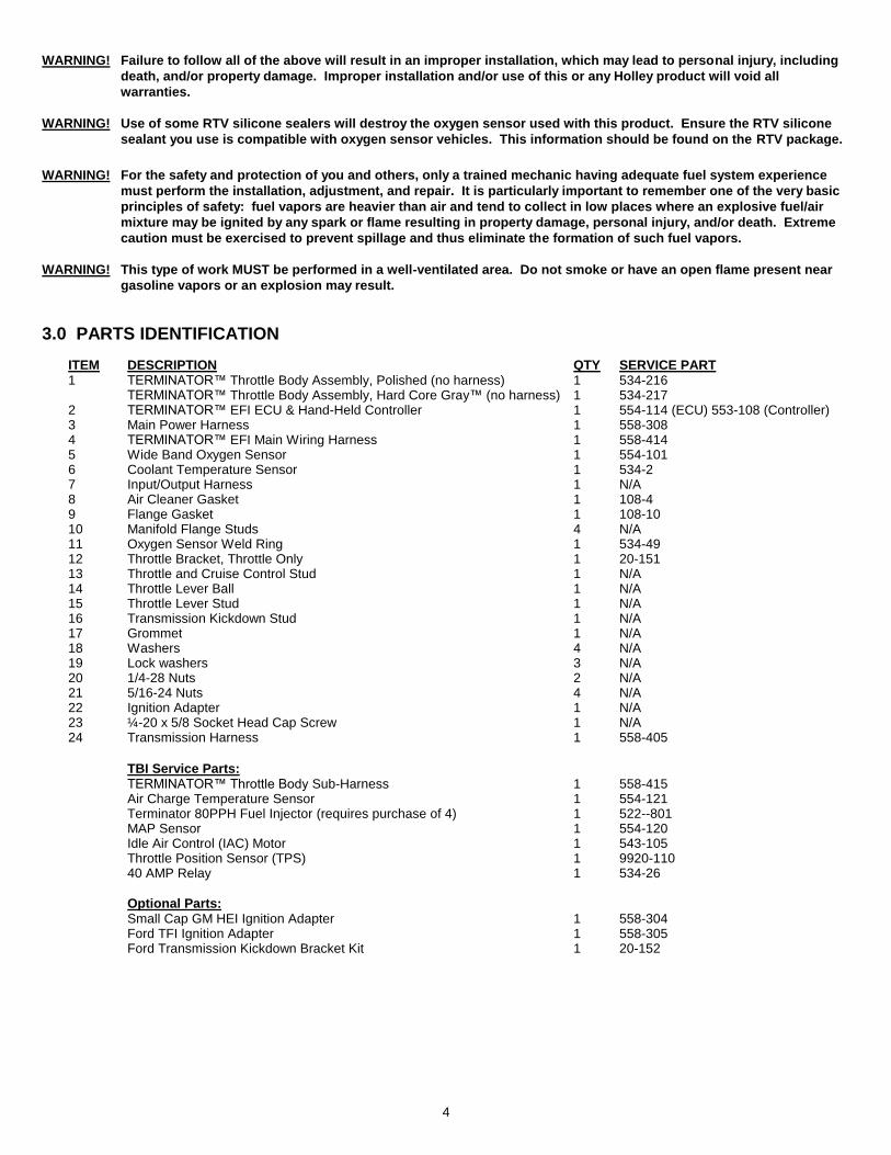
3.0 PARTS IDENTIFICATION
ITEM DESCRIPTION QTY SERVICE PART 1 TERMINATOR™ Throttle Body Assembly, Polished (no harness) 1 534-216 TERMINATOR™ Throttle Body Assembly, Hard Core Gray™ (no harness) 1 534-217 2 TERMINATOR™ EFI ECU & Hand-Held Controller 1 554-114 (ECU) 553-108 (Controller) 3 Main Power Harness 1 558-308 4 TERMINATOR™ EFI Main Wiring Harness 1 558-414 5 Wide Band Oxygen Sensor 1 554-101 6 Coolant Temperature Sensor 1 534-2 7 Input/Output Harness 1 N/A 8 Air Cleaner Gasket 1 108-4 9 Flange Gasket 1 108-10 10 Manifold Flange Studs 4 N/A 11 Oxygen Sensor Weld Ring 1 534-49 12 Throttle Bracket, Throttle Only 1 20-151 13 Throttle and Cruise Control Stud 1 N/A 14 Throttle Lever Ball 1 N/A 15 Throttle Lever Stud 1 N/A 16 Transmission Kickdown Stud 1 N/A 17 Grommet 1 N/A 18 Washers 4 N/A 19 Lock washers 3 N/A 20 1/4-28 Nuts 2 N/A 21 5/16-24 Nuts 4 N/A 22 Ignition Adapter 1 N/A 23 ¼-20 x 5/8 Socket Head Cap Screw 1 N/A 24 Transmission Harness 1 558-405
TBI Service Parts: TERMINATOR™ Throttle Body Sub-Harness 1 558-415 Air Charge Temperature Sensor 1 554-121 Terminator 80PPH Fuel Injector (requires purchase of 4) 1 522--801 MAP Sensor 1 554-120 Idle Air Control (IAC) Motor 1 543-105 Throttle Position Sensor (TPS) 1 9920-110 40 AMP Relay 1 534-26
Optional Parts: Small Cap GM HEI Ignition Adapter 1 558-304 Ford TFI Ignition Adapter 1 558-305 Ford Transmission Kickdown Bracket Kit 1 20-152

5
Item 1 Item 2 Item 3
Item 4 Item 5 Item 6 Item 7
Item 8 Item 9 Item 10 Item 11 Item 12
Item 13 Item 14 Item 15 Item 16 Item 17 Item 18 Item 19
Item 20 Item 21 Item 22 Item 23 Item 24
4.0 ADDITIONAL ITEMS REQUIRED FOR INSTALLATION
Fuel System Return Fuel Lines A 0-100 psi fuel gauge or pressure transducer is recommended to check for proper fuel pressure. PN 554-102 is a 0-100 PSI pressure sensor that can be purchased as well that will plug into the TERMINATOR™ harness to check and monitor fuel pressure. It requires a 1/8” NPT port for installation (Holley fuel pressure regulators have an 1/8” NPT port) In addition to the above list, the engine must be equipped with a four barrel intake manifold and the vehicle must be in good operating condition. Any square flange Holley type intake manifold will work. A spread bore intake manifold may work with no adapter as long as it is an aftermarket “universal flange” (meaning it has dual bolt patterns), and as long as it has enough material such that no vacuum leaks occur along the perimeter of the throttle body. If there is not enough material, a sealing plate (Weiand® PN 9006) can be used. Factory dual plane intakes will require an adapter (PN 17-6).

6
5.0 TOOLS REQUIRED FOR INSTALLATION
Standard wrench set Small blade screwdriver Allen Wrench set
Medium blade screwdriver #2 Phillips screwdriver Digital Volt meter
Drill and assorted bit sizes Hole saw (2”) (depending on ECU location) Terminal crimping tool
Factory Service Manual for your vehicle 02 Bung Installation (drilling, welding) An assistant is necessary for some installation and adjustment procedures and should be present for safety reasons.
6.0 COOLANT TEMPERATURE SENSOR INSTALLATION The coolant temperature sensor (Item 6) must be installed in a coolant passage in either the intake manifold or cylinder head. The sensor has 3/8” NPT threads. If only a ½” NPT port is available, an adapter will have to be used. It is best to drain the some of the coolant before the sensor is installed. Do not install the sensor in the thermostat housing, or in an area that will not see a constant flow of coolant.
7.0 REMOVAL OF EXISTING COMPONENTS 1. Disconnect the battery and remove the air cleaner. 2. Before disconnecting any vacuum hoses, it is a good idea to sketch out the vacuum hose routing. Using masking tape and a
permanent marker, mark all the vacuum hoses, vacuum sources, and ports before removing the old fuel delivery system. 3. Remove and discard the fuel line that connects to the carburetor from the mechanical fuel pump. This will not be needed in the
installation. Remove the throttle return springs and keep for later installation.
4. If required, replace the intake manifold at this time. Proceed to step six if this is not required. A 4-BARREL STOCK OR
AFTERMARKET SQUARE FLANGE INTAKE MANIFOLD, AS WELL AS SOME UNIVERSAL FLANGE AFTERMARKET SPREAD
BORE INTAKE MANIFOLDS ARE REQUIRED FOR THE INSTALLATION OF THE HOLLEY TERMINATOR™ EFI TBI system. An
option with some GM and Chrysler engines is to use manifold adapter Holley PN 17-6. This adapts the spread bore
carburetor manifold to the Holley square flange. 5. Place clean shop towels or rags into the manifold opening to prevent dirt or debris from entering the engine. Keep exposed ends of
the vacuum and fuel lines free from dirt or debris.
WARNING! Failure to cover the intake opening with a clean towel could result in dirt or debris entering the engine. Dirt or debris
in the induction system can cause engine damage, which may necessitate a complete engine overhaul.
6. Remove all traces of the old gasket material from the intake manifold mounting flange. DO NOT gouge the intake manifold sealing surface during removal of old gasket material. Failure to remove all traces of the old gasket material will result in vacuum leaks that will be difficult to detect later. Sealing flanges must be clean and dry before installation.
7. Remove the shop towels from the intake and vacuum out the intake channel to ensure no dirt or debris is left in the intake system.
Place a shop towel over the entire intake opening until you are ready to install the new TERMINATOR™ EFI TBI.
8.0 TERMINATOR™ EFI TBI SYSTEM INSTALLATION
8.1 Throttle Body
NOTE: A 4 barrel intake is required for the installation of the Holley TERMINATOR™ EFI TBI system.
1. Install the four manifold flange studs (Item 10) into the intake manifold. Install the throttle body gasket (Item 9) between the manifold and the 4 barrel throttle body injection unit. Check for sufficient thread engagement of the throttle body hold down studs and nuts.
DANGER! Check for proper clearance between engine components, such as the distributor, coil, etc., and the throttle body. If
any interference is found, correct the condition before continuing. Failure to do so can result in damage to the
engine components or the throttle body.
DANGER! Check for proper clearance between the air cleaner and the engine compartment cover hood. If any interference is
found, correct the condition before continuing. Failure to do so can result in damage to the compartment cover,
hood, or engine components. 2. Place the throttle body in position over the manifold flange studs with the throttle lever located on the driver’s side.
7
3. Tighten the throttle body down in a criss-cross pattern being careful not to over-tighten. Proper torque is 5-7 ft./lbs.
WARNING! Over tightening the TBI manifold flange hold-down-nuts may result in a warped or cracked throttle body. The TBI
hold down nuts should be tightened down progressively in a criss-cross pattern to 5-7 ft./lbs., to prevent leaks and
avoid causing damage to the throttle body. A TBI that has been damaged due to negligence of the owner will void
the warranty.
8.2 Throttle Connections
1. The throttle lever on the TERMINATOR™ is designed to directly connect to most throttle cables. Several throttle studs are included.
It is also designed to directly connect up to GM transmissions including TH350, TH200R, and TH700R4. A stud is included for most of these transmissions.
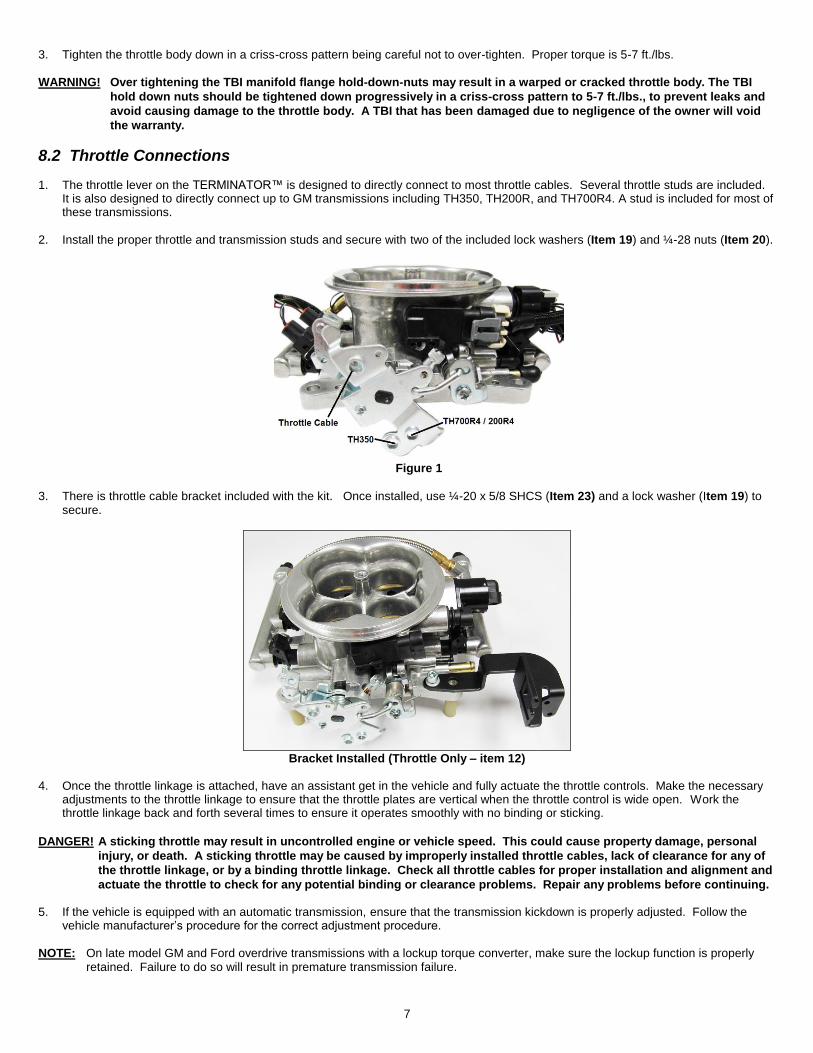
2. Install the proper throttle and transmission studs and secure with two of the included lock washers (Item 19) and ¼-28 nuts (Item 20).
Figure 1
3. There is throttle cable bracket included with the kit. Once installed, use ¼-20 x 5/8 SHCS (Item 23) and a lock washer (Item 19) to secure.
Bracket Installed (Throttle Only – item 12)
4. Once the throttle linkage is attached, have an assistant get in the vehicle and fully actuate the throttle controls. Make the necessary
adjustments to the throttle linkage to ensure that the throttle plates are vertical when the throttle control is wide open. Work the throttle linkage back and forth several times to ensure it operates smoothly with no binding or sticking.
DANGER! A sticking throttle may result in uncontrolled engine or vehicle speed. This could cause property damage, personal
injury, or death. A sticking throttle may be caused by improperly installed throttle cables, lack of clearance for any of
the throttle linkage, or by a binding throttle linkage. Check all throttle cables for proper installation and alignment and
actuate the throttle to check for any potential binding or clearance problems. Repair any problems before continuing. 5. If the vehicle is equipped with an automatic transmission, ensure that the transmission kickdown is properly adjusted. Follow the
vehicle manufacturer’s procedure for the correct adjustment procedure.
NOTE: On late model GM and Ford overdrive transmissions with a lockup torque converter, make sure the lockup function is properly retained. Failure to do so will result in premature transmission failure.
8
NOTE: On Chrysler vehicles, a lever extension will be needed, Holley PN 20-7. Van applications may require the use of throttle lever extension Holley PN 20-14.
6. Install external throttle return springs that you previously removed from the carburetor. External springs should be used in addition to
the springs on the throttle body itself. Have an assistant get in the vehicle and fully depress the accelerator pedal. Make the necessary adjustments to the throttle linkage to insure that the throttle reaches wide-open position when the accelerator is depressed. Work throttle linkage back and forth several times to ensure that it operates smoothly with no binding or sticking.
DANGER! Failure to attach the throttle return spring or a sticking throttle may result in uncontrolled engine or vehicle speed,
which could cause personal property damage, serious injury, or death.
8.3 MAP Sensor Installation and Vacuum Line Connections
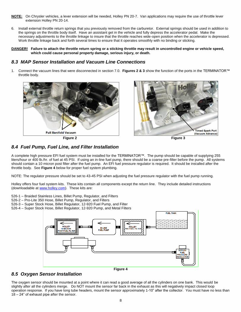
1. Connect the vacuum lines that were disconnected in section 7.0. Figures 2 & 3 show the function of the ports in the TERMINATOR™ throttle body.
Figure 2 Figure 3
8.4 Fuel Pump, Fuel Line, and Filter Installation
A complete high pressure EFI fuel system must be installed for the TERMINATOR™. The pump should be capable of supplying 255 liters/hour or 400 lb./hr. of fuel at 45 PSI. If using an in-line fuel pump, there should be a coarse pre-filter before the pump. All systems should contain a 10 micron post filter after the fuel pump. An EFI fuel pressure regulator is required. It should be installed after the
throttle body. See Figure 4 below for proper fuel system plumbing. NOTE: The regulator pressure should be set to 43-45 PSI when adjusting the fuel pressure regulator with the fuel pump running. Holley offers four fuel system kits. These kits contain all components except the return line. They include detailed instructions (downloadable at www.holley.com). These kits are: 526-1 – Braided Stainless Lines, Billet Pump, Regulator, and Filters 526-2 – Pro-Lite 350 Hose, Billet Pump, Regulator, and Filters 526-3 – Super Stock Hose, Billet Regulator, 12-920 Fuel Pump, and Filter 526-4 – Super Stock Hose, Billet Regulator, 12-920 Pump, and Metal Filters
Figure 4
8.5 Oxygen Sensor Installation
The oxygen sensor should be mounted at a point where it can read a good average of all the cylinders on one bank. This would be slightly after all the cylinders merge. Do NOT mount the sensor far back in the exhaust as this will negatively impact closed loop operation response. If you have long tube headers, mount the sensor approximately 1-10” after the collector. You must have no less than 18 – 24” of exhaust pipe after the sensor.

9
TERMINATOR™ EFI systems come with a Bosch wideband oxygen sensor (Item 5). Make sure your sensor looks like Figure 5.
Figure 5
8.5.1 Oxygen Sensor Mounting Procedure
NOTE: Never run the engine with the oxygen sensor installed if it is not plugged in and powered by the ECU, or it will be damaged. If you need to plug the hole temporarily, use an O2 sensor plug or a spark plug with an 18mm thread.
NOTE: Someone with experience in welding exhaust systems should install the oxygen sensor boss. Any competent exhaust shop will be able to perform this task at a minimum cost. (Note: If you weld on the car, make sure all wiring to the ECU is disconnected, and its best to remove the ECU from the vehicle when welding).
WARNING! Use of leaded fuel will degrade an oxygen sensor. Prolonged use is not recommended unless periodic replacement
is performed.
WARNING! Use of some RTV silicone sealers will destroy the oxygen sensor used with this product. Ensure the RTV silicone
sealant you use is compatible with oxygen sensor vehicles. This information should be found on the RTV package.
1. Locate a position for the oxygen sensor as close to the engine as possible. If your vehicle has catalytic converters, the oxygen sensor MUST be located between the engine and the catalytic converters.
Figure 6
NOTE: The oxygen sensor should be mounted in such a way that the condensation in the exhaust tubing will not enter the sensor.
Mount the O2 sensor in the upper half of the exhaust tubing, with the angle “x”, shown above, being greater than 10°. Figure 6 indicates that the sensor can be mounted on either side of the exhaust tubing.
2. Drill a 7/8” hole in the location picked for the sensor. Weld the threaded boss into the 7/8” hole. Weld all the way around the boss to
insure a leak proof connection. Install the oxygen sensor into the threaded boss and tighten securely. It is a good idea to add anti-seize to the threads to aid in removal. Do not get any anti-seize on the tip of the sensor.
3. On vehicles equipped with an AIR pump, the oxygen sensor must be mounted before the AIR injection into the exhaust, or the AIR
pump must be disconnected. Holley recommends that if the AIR is injected into both exhaust manifolds, mount the oxygen sensor into the pipe immediately after the exhaust manifold. Disconnect the AIR pump tube from the exhaust manifold and plug both ends. Check with local ordinances for the legality of this procedure in your area.
WARNING! Failure to disconnect the AIR pump or locating the oxygen sensor downstream from AIR injection will result in an
extremely rich mixture, which could cause drivability problems and severe engine damage.
8.6 ECU Mounting
The ECU can be mounted inside the passenger compartment (preferable location) or in the engine compartment. If mounted in the engine compartment, follow these guidelines:
The ECU should be located such that it isn’t being directly hit by water or road debris.
It should also be located such that it isn’t extremely close to exhaust manifolds or headers.
It should be mounted such that it is as far away from spark plug wires, CD ignition boxes, or other “electrically noisy” devices as is reasonable possible.
Make sure the connector end of the ECU is pointed DOWN such that water can’t make its way into the ECU terminals.

10
The ECU comes with mounting hardware (stainless steel screws and nuts). The ECU has plastic shoulders on the mounting ears. DO NOT REMOVE THEM. Do not over-tighten the mounting hardware if the ECU is not mounted on a flat surface.
9.0 WIRING
This section overviews how to properly install the wiring harnesses for this system.
9.1 Important Wiring “Do’s and Don’ts”
An EFI system depends heavily on being supplied a clean and constant voltage source. The grounds of an electrical system are just as important as the power side.
TERMINATOR™ ECU’s contain multiple processing devices that require clean power and ground sources. The wiring harnesses for them must be installed in such a manner that they are separated from “dirty” power and ground sources.
DO’S
Install the main power and ground directly to the battery. To the POSTS/TERMINALS, not to any other place.
Keep sensor wiring away from high voltage or “noisy/dirty” components and wiring, especially secondary ignition wiring (plug wires), ignition boxes and associated wiring. It is best that the plug wires not physically contact any EFI wires.
Properly crimp or crimp and solder any wire connections. Apply quality heat shrink over any of these connections.
It is critical that the engine has a proper ground connection to the battery and chassis.
DON’TS
NEVER run high voltage or “noisy/dirty” wires in parallel (bundle/loom together) with any EFI sensor wiring. If wires need to cross, try to do so at an angle.
Do not use the electric fan outputs to directly power a fan. They must only trigger a relay.
Do not use improper crimping tools.
Don’t use things like “t-taps”, etc. Use proper crimpers/solder and heat shrink.
It is never recommended to splice/share signal wires (such as TPS, etc.) between different electronic control units (i.e. “piggyback”).
Do not connect the red/white switched +12V wire to “dirty” sources, such as the ignition coil, audio systems, or 12V sources connected to HID head lamps.
10.0 WIRING HARNESS INSTALLATION
The TERMINATOR™ throttle body comes with sensors pre-wired for easy installation.
10.1 Main Power/Battery Connection
The TERMINATOR™ ECU has a main battery power and ground connector on the right side of the ECU. The bottom position, Terminal “A” is the ground (black wire). The black wire should go to the negative post DIRECTLY on the battery. The upper position, Terminal “B” is the positive terminal (red wire). The red wire should go to the positive post DIRECTLY on the battery. If you have a “dual post” battery, it is a great idea to purchase separate posts/studs to connect the ECU power and ground to the non-used terminals. Always use the
fused power cable (Item 3) with the proper connectors supplied by Holley only. Don’t connect to the ECU until after ALL wiring and installation is performed.
Figure 7
11.0 PRIMARY HARNESS INSTALLATION AND SENSOR CONNECTIONS
These sections review the Main Harness installation and sensor connections that must be completed. The Main Harness (Item 4) is the primary harness that supports all the primary engine sensors, fuel and ignition. There are two main connectors for this harness that plug into the ECU.
11
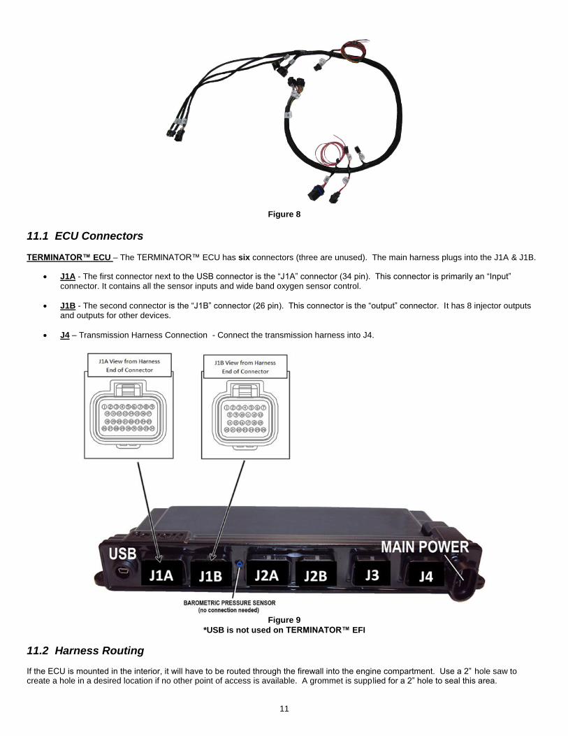
Figure 8
11.1 ECU Connectors
TERMINATOR™ ECU – The TERMINATOR™ ECU has six connectors (three are unused). The main harness plugs into the J1A & J1B.
J1A - The first connector next to the USB connector is the “J1A” connector (34 pin). This connector is primarily an “Input” connector. It contains all the sensor inputs and wide band oxygen sensor control.
J1B - The second connector is the “J1B” connector (26 pin). This connector is the “output” connector. It has 8 injector outputs and outputs for other devices.
J4 – Transmission Harness Connection - Connect the transmission harness into J4.
Figure 9
*USB is not used on TERMINATOR™ EFI
11.2 Harness Routing If the ECU is mounted in the interior, it will have to be routed through the firewall into the engine compartment. Use a 2” hole saw to create a hole in a desired location if no other point of access is available. A grommet is supp lied for a 2” hole to seal this area.

12
If the ECU is mounted in the engine compartment, the hand-held tuning module cable will have to be routed to the “CAN” connector on the main harness (located near the ECU connector main connector). This is assuming you want to access the hand-held module after startup. This will require routing the small CAN connector somewhere through the firewall. Connect the J1A and J1B connectors of the main harness into the ECU. About 18” from the ECU main connectors is a 40A Relay. This powers the injectors and fuel pump. There is also a 20 amp fuse for the injectors and fuel pump pre-installed in this location. The transmission harness should be routed as desired.
11.3 Sensor Connections & Outputs The following indicates the primary sensors that are required to be connected. Each connector on the main harness is labeled with the sensor name. The name on this label for each sensor is in parenthesis below.
11.3.1 Throttle Body Bulkhead Connector (Bulkhead)
Connect the 14 bin bulkhead connector in the main harness to the connector of the throttle body.
11.3.2 Coolant Temperature Sensor (CTS)
Connect to the Coolant Temperature sensor which should have been installed in an engine coolant passage.
Figure 10 CTS
11.3.3 Wide Band Oxygen Sensor (WB02)
Connect to the oxygen sensor connector to the oxygen sensor previously installed. If you need an extension cable, one is available from Holley (P/N 534-199). The TERMINATOR™ systems are intended to be used with a Bosch wide band oxygen sensor supplied by Holley.
Figure 11 WBO2
11.3.4 Fuel Pressure (Fuel)
A fuel pressure transducer connector is pre-installed in the main harness. The system is plug-and-play configured for a Holley 100 PSI pressure transducer (can be purchased under PN 554-102). If these are not connected to a pressure transducer, the Fuel Pressure will read “LEr” on the hand-held display. This will not cause any issues. Connect to the transducer (if installed).
Figure 12 Fuel

13
11.3.5 CANbus – Handheld (CAN) The handheld controller is used for create of an initial calibration for the system, allows for simple tuning changes to be performed, and is also used to view various information of the EFI system. It should be installed such the handheld controller can be easily used in the passenger compartment. The handheld has a single four pin connector that connects to the main harness. Plug the connector into the main wiring harness into the plug marked “CAN”. This plug is located 21 inches from the ECU connector. The handheld does not have to remain in the vehicle or utilized after the vehicle is set up and running properly. There is a second connector marked “CAN 2”. This is for additional CAN devices. See Figure 13.
Figure 13 Harness to Handheld
11.3.6 Ignition (IGN) There is a 10 pin connector marked “IGN”. This is to connect to various ignition systems. This is not required for some app lications.
Figure 14
12.0 LOOSE WIRES
Figure 15
The following loose wires in the main wiring harness should be connected as follows on all systems. All of these wires come out of the harness about 40” from the ECU connectors except for the “12V Switched” wire.

14
12V Switched – Color = Red/White – Should be connected to a clean +12 volt power source. Power source should only be active when the ignition is on. Make sure source has power when engine is cranking as well (check with voltmeter). Not all sources apply power when
the ignition switch is in “cranking” position. This wire is located approximately 7” from the ECU connectors. DO NOT connect to a
“DIRTY” source like an ignition coil! Refer to Figure 15.
12V Battery – Color = Red – Should be connected directly to the battery. This powers the fuel pump and fuel injectors. This wire is protected by a fuse in a sealed fuse holder. The fuse holder is located about 18” from the ECU connector. A fuse is pre-installed (20A).
12V Fuel Pump – Color = Green - Used to directly power a fuel pump (+12 volt). Do not use this wire to power fuel pumps that require over 15 Amps. For high current pumps, use this wire to trigger a separate relay and use larger gauge wire to feed the pump - 10 gauge is recommended. The pump that include with TERMINATOR™ systems draws less than 10 Amps and can be powered directly by this wire. The fuel pump also requires a ground wire. Run a wire from the negative side of the fuel pump. Connect it to a solid chassis/frame ground.
Chassis Ground – Color = Black – Connect to a chassis ground point that has excellent connectivity with both the engine and battery. This ground should not be connected at the same location as other grounds.
“Coil – ” – Color = Yellow – See section 13.0 below. This is an RPM input wire used for some applications.
13.0 IGNITION/ENGINE SPEED INPUT The most important signal for the ECU is the Engine Speed input. It is critical that this is configured and wired correctly or poor performance will result. There are 3 engine speed options on the TERMINATOR™ systems. Each one is wired differently. If these are wired incorrectly, it is easily possible to permanently damage the ECU so pay close attention to proper wiring. These options are described below and wiring diagrams are supplied below the descriptions:
OPTION 1) “Coil -” engine speed input – Use this if:
You are using a stock type mechanical advance distributor with a stock inductive ignition coil. Examples of this would be any older style points distributor, a 1974-1981 GM large cap HEI.
Do NOT use this input if you are using an aftermarket Capacitive Discharge (CD) ignition system such as a MSD, Mallory, or others. The ECU will be damaged if you connect to a capacitive discharge type ignition coil.
NOTE: Using this input, the EFI will NOT control the ignition timing of the engine. The timing will be based on the distributor initial, mechanical, and vacuum advance, just like it did with a carburetor.
OPTION 2) “Tach Out” engine speed input -
If you are using an aftermarket Capacitive Discharge (CD) ignition system such as a MSD, Mallory, or others, you need to connect to the “Tach Out” connection or wire these systems provide. This is a 12 volt square wave output.
CAUTION! NEVER, NEVER connect any of the EFI wires to the coil on any CD type ignition system. The ECU will be permanently
damaged!
NOTE: Using this input, the EFI will NOT control the ignition timing of the engine. The timing will be based on the distributor ini tial, mechanical, and vacuum advance, just like it did with a carburetor.
OPTION 3) “GM Small Cap HEI” Computer Controlled Distributor (Requires Holley Ignition Adapter PN 558-304) –
Small and Big Block Chevy engines can use a small cap GM HEI computer controlled distributor that was available on factory GM vehicles from the 1980’s through mid-1990’s. This distributor provides an engine speed signal to the EFI, as well as allowing the EFI to control the ignition timing.
Figure 16 Distributor and Close Up of Distributor
OPTION 4) “Ford TFI” Computer Controlled Distributor (Requires Holley Ignition Adapter PN 558-305) –
Ford Sequentially Injected 5.0-5.8L engines from 1987-1995 used this distributor.
15
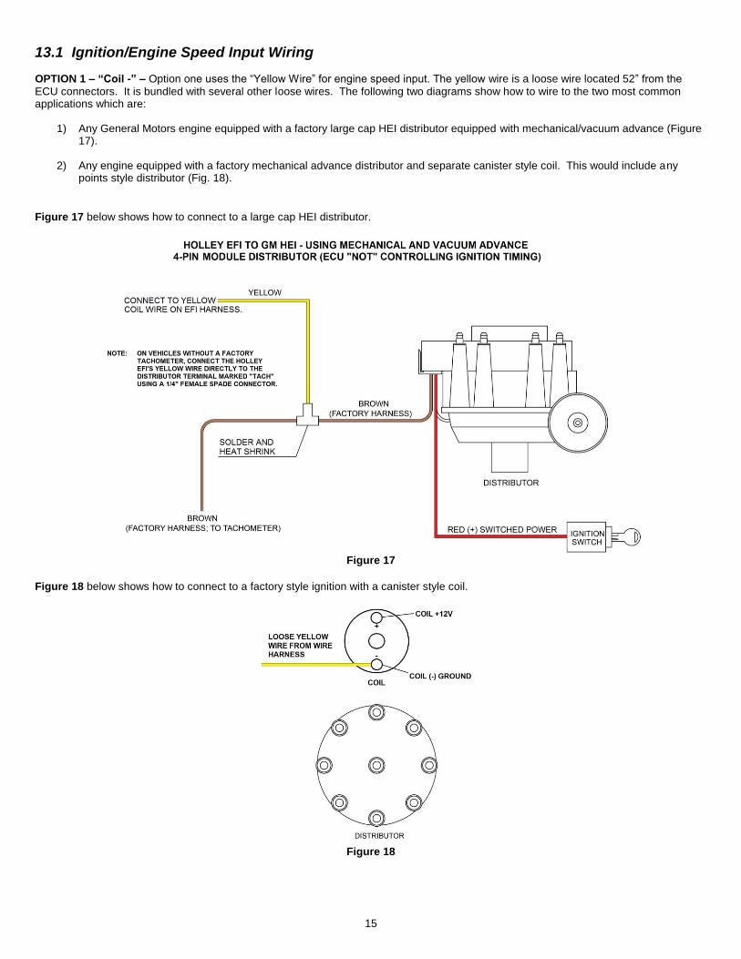
13.1 Ignition/Engine Speed Input Wiring
OPTION 1 – “Coil -” – Option one uses the “Yellow Wire” for engine speed input. The yellow wire is a loose wire located 52” from the ECU connectors. It is bundled with several other loose wires. The following two diagrams show how to wire to the two most common applications which are:
1) Any General Motors engine equipped with a factory large cap HEI distributor equipped with mechanical/vacuum advance (Figure 17).
2) Any engine equipped with a factory mechanical advance distributor and separate canister style coil. This would include any points style distributor (Fig. 18).
Figure 17 below shows how to connect to a large cap HEI distributor.
Figure 17
Figure 18 below shows how to connect to a factory style ignition with a canister style coil.
Figure 18
16
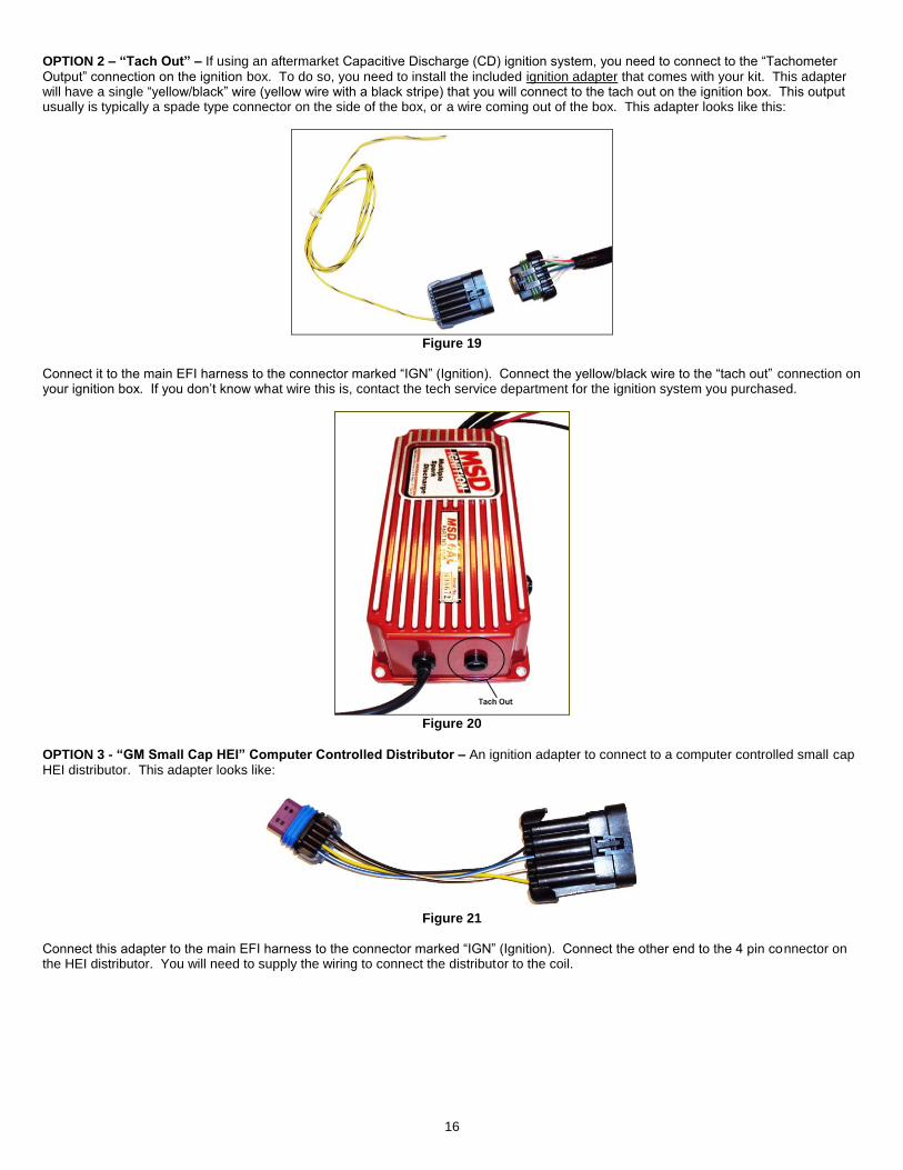
OPTION 2 – “Tach Out” – If using an aftermarket Capacitive Discharge (CD) ignition system, you need to connect to the “Tachometer Output” connection on the ignition box. To do so, you need to install the included ignition adapter that comes with your kit. This adapter will have a single “yellow/black” wire (yellow wire with a black stripe) that you will connect to the tach out on the ignition box. This output usually is typically a spade type connector on the side of the box, or a wire coming out of the box. This adapter looks like this:
Figure 19
Connect it to the main EFI harness to the connector marked “IGN” (Ignition). Connect the yellow/black wire to the “tach out” connection on your ignition box. If you don’t know what wire this is, contact the tech service department for the ignition system you purchased.
Figure 20
OPTION 3 - “GM Small Cap HEI” Computer Controlled Distributor – An ignition adapter to connect to a computer controlled small cap HEI distributor. This adapter looks like:
Figure 21
Connect this adapter to the main EFI harness to the connector marked “IGN” (Ignition). Connect the other end to the 4 pin connector on the HEI distributor. You will need to supply the wiring to connect the distributor to the coil.

17
Figure 22 shows how to wire when NOT using an aftermarket CD box. Figure 23 Shows how to wire when using an aftermarket CD box.
Figure 22
Figure 23
18
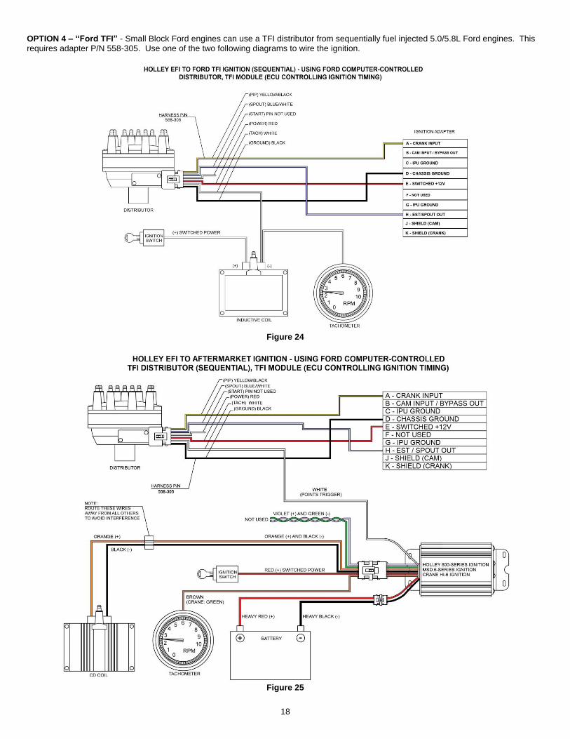
OPTION 4 – “Ford TFI” - Small Block Ford engines can use a TFI distributor from sequentially fuel injected 5.0/5.8L Ford engines. This requires adapter P/N 558-305. Use one of the two following diagrams to wire the ignition.
Figure 24
Figure 25

19
14.0 ADDITIONAL OUTPUTS There are 3 optional outputs available on the system that can be used for the following features:
Air Conditioning Shutdown at wide open throttle
Electric Fan #1 output
Electric Fan #2 output
There outputs are located in the “Input/Output” connector. This is a 3 Pin connector is located about 52 inches from the ECU. A mating harness is included with the system. The following indicates proper wiring for these features.
A/C Shutdown – This output will provide a +12 volt output a defined throttle position. This output can be used to trigger a relay that deactivates the A/C at higher throttle positions. This may require the installation of a 5 pole relay in the existing A/C wiring. This wire is located in pin A of the 3 pin Input/Output connector and is Gray with a Yellow stripe.
Electric Fan #1 output – This output will provide a ground output to trigger a relay used for a cooling fan. This output should never be directly connected to a fan, but the relay that powers the fan. It should be connected to the ground trigger of the relay. This wire is located in pin B of the 3 pin Input/Output connector and is Gray with a Black stripe.
Electric Fan #2 output – This output will provide a ground output to trigger a relay used for a cooling fan. This output should never be directly connected to a fan, but the relay that powers the fan. It should be connected to the ground trigger of the relay. This wire is located in pin C of the 3 pin Input/Output connector and is Gray with a Green stripe.
Figure 26
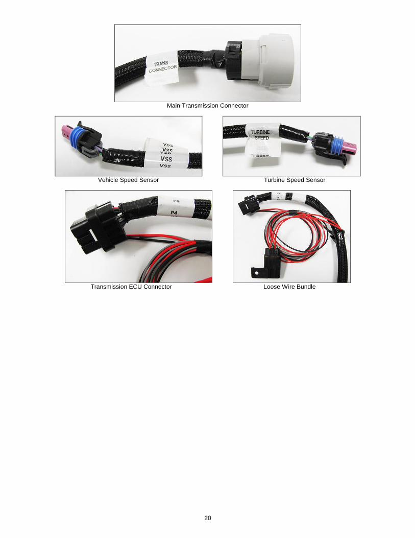
14.1 Transmission Wiring The transmission harness can be used on 4L60E, 4L65E, 4L70E, 4L80E, and 4L85E transmissions. Each connector should be labeled.
Transmission ECU Connector (P4) – Plugs into the ECU. Plugs into the last connector opposite the main harness.
Main Transmission Connector – Simply plugs into the connector on the transmission. Located on the driver’s side of a 4L80E (installed horizontally) and the passenger side on a 4L60E (installed vertically).
Vehicle Speed Sensor (VSS)/Transmission Output Speed Sensor (OSS) – Located on the rear drivers side on a 4L80E and the rear passengers side on a 4L60E
Turbine Speed Sensor – The 4L60E does not have a turbine speed sensor. It is located towards the front driver’s side on a 4L80E. Note that a 4L70E has one internally wired, but is not connected to the Holley harness. The turbine speed sensor is not used for any calculations in the ECU, just for monitoring purposes.
Brake Switch (Grey) – Wired to the brake light switch. This must be installed to a +12v source (as most brake light switches are). This input is used to unlock the torque converter when the brakes are applied.
Ground (Black) – Connect to a good chassis/engine ground source
Power (Red) – Supplies power to the transmission solenoids. This should be connected to a +12v switched power source (must be capable of supplying 5 amps).
NOTE: The power supplying this wire must NOT be tied to the same point that the ECU switched power wire (red/white wire) is connected to. If they are tied together, the transmission power could back-feed power to the ECU and the ECU/engine will not shut off when the key is turned off. Use a relay or separate switched ignition power pickup point to supply power to the transmission harness.
20
Main Transmission Connector
Vehicle Speed Sensor Turbine Speed Sensor
Transmission ECU Connector Loose Wire Bundle

21
APPENDIX 1.0 PINOUT
The following shows pins that are used on TERMINATOR™ systems. Pins that are not populated on TERMINATOR™ systems are denoted with an asterisk (*).
J1A Connector J1B Connector
Pin Function Pin Function
A1 Coil – Input B1 IAC A Lo
A2 Fuel Pump Out (+12v) (10A Max) B2 IAC A Hi
A3 * B3 Fan #2 Output (ground)
A4 * B4 *
A5 TPS Input B5 *
A6 * B6 *
A7 WB1 COMPR2 B7 *
A8 WB1 Shield B8 IAC B Lo
A9 WB HTR - B9 IAC B Hi
A10 Switched +12v Input B10 Fan #1 Output (ground)
A11 Manifold Air Temp Input B11 *
A12 * B12 A/C Shutdown (+12v)
A13 * B13 Injector D Output
A14 Cam/Crank Ground B14 Ground
A15 * B15 *
A16 WB1 COMPR1 B16 *
A17 WB1 VS-/IP+ B17 *
A18 Sensor Ground B18 *
A19 Engine Coolant Temp Input B19 Injector A Output
A20 * B20 EST 12V Output
A21 * B21 *
A22 Cam Input / Bypass Out B22 *
A23 Map Sensor Input B23 *
A24 CAN Lo B24 *
A25 WB1 VS+ B25 Injector C Output
A26 Sensor +5v B26 Injector B Output
A27 *
A28 EST/Spout Output
A29 *
A30 Crank Speed Input
A31 Fuel Pressure Input
A32 CAN Hi
A33 WB1 IP+
A34 WB HTR +
*Position Not Populated
15.0 PREVIOUS INSTALLATION REQUIRED At this point, the installation of your EFI system should be 100 percent complete. The ECU, TERMINATOR™ Handheld controller, throttle body and intake hardware, all sensors, wiring, fuel pump, regulator and return line, and all other hardware should be installed. The vehicle should be ready to start and run. If this is not the case, refer to the hardware installation manual included with your particular system.
16.0 TERMINATOR™ INSTRUCTIONS AND TUNING The TERMINATOR™ EFI systems are designed to be easy to use for the first time EFI tuner. The instructions are set up in that manner as well. These instructions will not get into detail about EFI theory and operation. They will provide the steps necessary to get you up and running quickly. The TERMINATOR™ system allows for the user to perform some basic changes to the tuning if they desire to do so. The instructions are sequenced to get you up and running so you can enjoy your vehicle, then review some of the parameters that can be adjusted to fine tune your vehicle at a later time if desired.
22
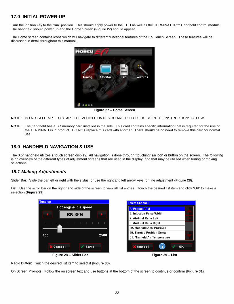
17.0 INITIAL POWER-UP Turn the ignition key to the “run” position. This should apply power to the ECU as well as the TERMINATOR™ Handheld control module.
The handheld should power up and the Home Screen (Figure 27) should appear. The Home screen contains icons which will navigate to different functional features of the 3.5 Touch Screen. These features will be discussed in detail throughout this manual.
Figure 27 – Home Screen
NOTE: DO NOT ATTEMPT TO START THE VEHICLE UNTIL YOU ARE TOLD TO DO SO IN THE INSTRUCTIONS BELOW.
NOTE: The handheld has a SD memory card installed in the side. This card contains specific information that is required for the use of the TERMINATOR™ product. DO NOT replace this card with another. There should be no need to remove this card for normal use.
18.0 HANDHELD NAVIGATION & USE The 3.5” handheld utilizes a touch screen display. All navigation is done through “touching” an icon or button on the screen. The following is an overview of the different types of adjustment screens that are used in the display, and that may be utilized when tuning or making selections.
18.1 Making Adjustments
Slider Bar: Slide the bar left or right with the stylus, or use the right and left arrow keys for fine adjustment (Figure 28). List: Use the scroll bar on the right hand side of the screen to view all list entries. Touch the desired list item and click ‘OK’ to make a
selection (Figure 29).
Figure 28 – Slider Bar Figure 29 – List
Radio Button: Touch the desired list item to select it (Figure 30).
On Screen Prompts: Follow the on screen text and use buttons at the bottom of the screen to continue or confirm (Figure 31).

23
Figure 30 – Radio Button Figure 31 – On Screen Prompts
Figure 32 – Graph Figure 33 – Edit Options
Digitally: Selecting this option enables slider bar adjustment of individual data points on the graph or the entire curve. Graphically: Selecting this option enables single point or whole curve adjustment. A stylus may be used to select and drag data on the graph screen. Entire Curve: Selecting this will ‘lock’ all the data points together allowing the entire curve to be shifted up or down Point by Point: Selecting this will allow point by point curve adjustment for fine tuning. Live Data 1 & 2: This will enable live telemetry on the graph screen making fine tuning easier.
19.0 HOME SCREEN
The HOME SCREEN has 4 selections (Figure 34). They are explained in more detail later in the instructions. TUNING – Allows for various parameters to be easily adjusted. MONITOR – A variety of gauge and dash displays. FILE – Saves and loads files. Also shows information about the ECU and handheld controller. WIZARDS – Creates a base calibration and performs the “TPS Autoset” function.
Figure 34
24
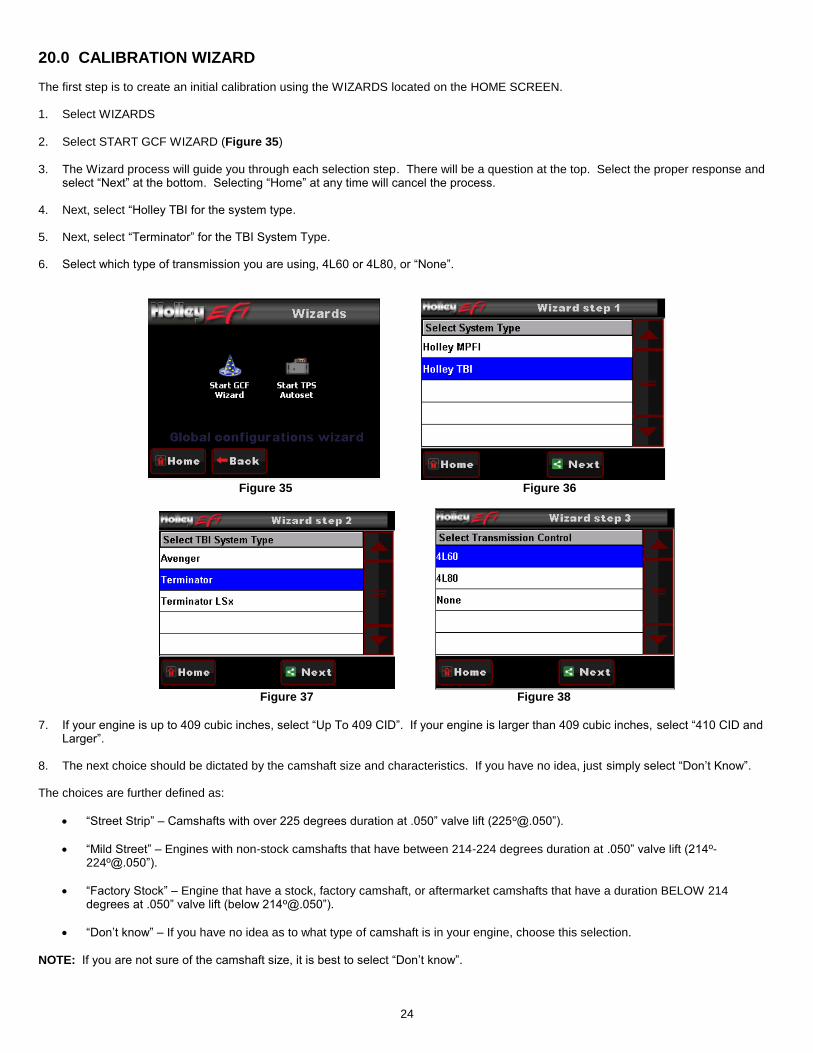
20.0 CALIBRATION WIZARD The first step is to create an initial calibration using the WIZARDS located on the HOME SCREEN. 1. Select WIZARDS
2. Select START GCF WIZARD (Figure 35)
3. The Wizard process will guide you through each selection step. There will be a question at the top. Select the proper response and select “Next” at the bottom. Selecting “Home” at any time will cancel the process.
4. Next, select “Holley TBI for the system type.
5. Next, select “Terminator” for the TBI System Type.
6. Select which type of transmission you are using, 4L60 or 4L80, or “None”.
Figure 35 Figure 36
Figure 37 Figure 38
7. If your engine is up to 409 cubic inches, select “Up To 409 CID”. If your engine is larger than 409 cubic inches, select “410 CID and
Larger”.
8. The next choice should be dictated by the camshaft size and characteristics. If you have no idea, just simply select “Don’t Know”. The choices are further defined as:
“Street Strip” – Camshafts with over 225 degrees duration at .050” valve lift (225º@.050”).
“Mild Street” – Engines with non-stock camshafts that have between 214-224 degrees duration at .050” valve lift (214º-224º@.050”).
“Factory Stock” – Engine that have a stock, factory camshaft, or aftermarket camshafts that have a duration BELOW 214 degrees at .050” valve lift (below 214º@.050”).
“Don’t know” – If you have no idea as to what type of camshaft is in your engine, choose this selection.
NOTE: If you are not sure of the camshaft size, it is best to select “Don’t know”.

25
Figure 38 Figure 39
9. Next, you need to select whether the ECU will be controlling the ignition timing. Select “Yes” ONLY if you are using a GM small
cap computer controlled HEI distributor or Ford TFI distributor. These are the only ignition distributors that allow the ECU timing control using the TERMINATOR™ system. All other ignition/distributor types must be a standard mechanical advance type used on any carbureted application. If you select “Yes”, proceed to step 10. If you select “No”, proceed to step 11.
Figure 40 Figure 40
10. Select “GM Small HEI” or “Ford TFI”. Proceed to step 12.
11. If you are not controlling timing, you will have the following two choices. It is important the correct item is selected, as well as to
double-check that you used the proper input wire when the vehicle was wired.
“Coil – (neg)-” – Select this if you are NOT using an aftermarket Capacitive Discharge (CD) ignition box such as a MSD, Mallory, or others. This is for stock, factory inductive ignition coils. Examples would be a factory GM large cap HEI, or a points style ignition with a canister coil. You should have connected the solid yellow wire in the harness to the negative side of the ignition coil when the wiring was performed.
“CD Box Tach Out” – Select this if you are using an aftermarket Capacitive Discharge (CD) ignition box such as a MSD, Mallory, or others. When you wired the vehicle, you should have used an ignition adapter harness that had a yellow/black wire that you connected to the “tach out” on the ignition box. Nothing should have been wired directly to the ignition coil.
NOTE: If you are unsure of this selection, or wiring, contract Holley tech service. Damage to the ECU will result due to improper wiring.
Figure 41 Figure 42
26
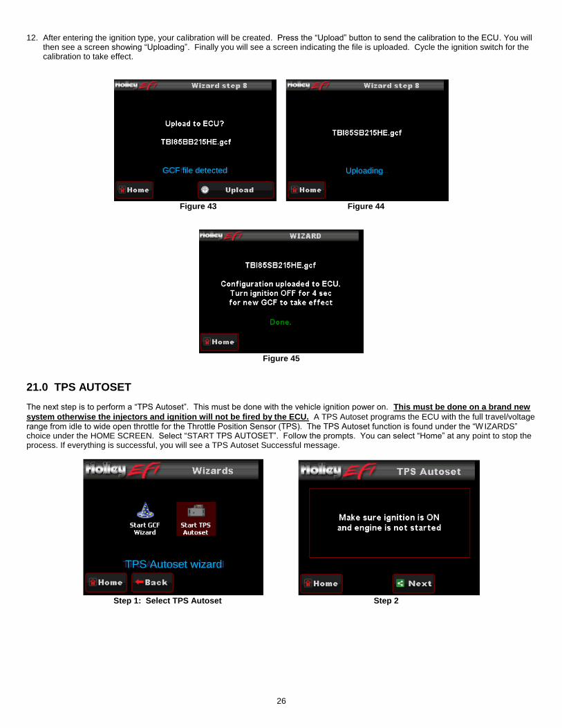
12. After entering the ignition type, your calibration will be created. Press the “Upload” button to send the calibration to the ECU. You will then see a screen showing “Uploading”. Finally you will see a screen indicating the file is uploaded. Cycle the ignition switch for the calibration to take effect.
Figure 43 Figure 44
Figure 45
21.0 TPS AUTOSET
The next step is to perform a “TPS Autoset”. This must be done with the vehicle ignition power on. This must be done on a brand new
system otherwise the injectors and ignition will not be fired by the ECU. A TPS Autoset programs the ECU with the full travel/voltage range from idle to wide open throttle for the Throttle Position Sensor (TPS). The TPS Autoset function is found under the “W IZARDS” choice under the HOME SCREEN. Select “START TPS AUTOSET”. Follow the prompts. You can select “Home” at any point to stop the process. If everything is successful, you will see a TPS Autoset Successful message.
Step 1: Select TPS Autoset Step 2
Uploading GCF file detected
TPS Autoset wizard

27
Step 3 Step 4: Select ‘Done’
22.0 TRANSMISSION SETUP
At this time, if an electronic transmission is being used, basis drivetrain parameters need to be set up.
22.1 Transmission Selecting TRANSMISSION brings up the following menu. There are two areas you can modify; TRANS SETUP and SPEED CALC. These are reviewed below.
Figure 46
22.1.1 Trans Setup
Transmission RPM: If this RPM is exceeded when in manual shift mode, the transmission will upshift automatically. If a manual downshift is performed, and this RPM will be exceeded, the downshift will not be allowed. This value should be slightly higher than the WOT shift points.
Figure 47
Transmission setup

28
22.1.2 Speed Calc Four pieces of information will need to be entered via the 3.5 handheld to attain proper speedometer calibration when using Holley transmission control
Tire Diameter – From 10.0 to 70.0 inches (Example 26.4)
Rear Gear Ratio – From 0.50 to 9.99 (Example 3.73)
Speedometer Output – Enabled or Disabled
Pulses Per Mile (PPM) – The pulses produced per mile
NOTE: The terminator harness does not have a Speedometer output wire, nor is the calibration programmed for it.
Figure 48 Figure 49
Figure 50 Figure 51
23.0 SENSOR VERIFICATION
Before starting the vehicle, verify that all of the sensors are reading properly. At this time, turn the key off, and cycle it back on. At this time you should hear the fuel pump come on and run for 5 seconds. Check for fuel leaks at this time as well.
On the HOME SCREEN, select the MONITOR tab. This will bring up various options. Select the “Monitors” screen. You will see a screen called “Sensors”. Select this. With the key on and the engine off, these sensors should read as follows:
MAP (Manifold Air Pressure Sensor) – Should read from 95-102. At high elevations it could read as low as 75.
TPS (Throttle Position Sensor) – Should read 0. Slowly depress the throttle to wide open. It should read 100 at wide open throttle. If it reads 1-2, you may want to lower the idle screw on the throttle body.
MAT (Manifold Air Temperature Sensor) – reads current air temperature
CTS (Coolant Temperature Sensor) – reads engine temperature. If the engine is “cold”, it should read almost the same as the MAT sensor.
Battery – Will read battery voltage. Should be 12.0 volts minimum. If ANY of these sensors are not reading properly, this must be resolved before the engine is started.

29
24.0 STARTUP The vehicle should be ready to be started. Open the sensors screen. Make sure the TPS is reading 0. If it does not, do a TPS AUTOSET, or if it is reading 1-2%, close the idle screw on the throttle body slightly. Crank the engine and look at the RPM parameter. It should change to “Syncng”, indicating the ECU is syncing with the RPM signal for an instant, then show an RPM signal. The engine should fire and run and come to an idle. If you do not get an RPM signal, there is an error in the wiring or system setup. Call Holley Tech service for advice. If the engine starts but is idling too low and appears to be struggling for air, you may have to open the throttle body idle speed screw at this time. If you move the screw, you will need to perform a TPS Autoset.
25.0 SETTING IGNITION TIMING If you are using a computer controlled GM HEI or Ford TFI distributor, you must sync up the ignition timing with the ECU. You must have a timing light to perform this. You will possibly need a dial-back timing light or a harmonic balancer that is degreed up to 40 degrees. Again, open the Sensors monitor screen. You will see the “Ign Timing” parameter which will display what the commanded ignition timing is. Rev the engine up (CAREFULLY) to approximately 2000 RPM. Note the timing value on the handheld. Using the timing light, turn the distributor until the timing you see with the timing light matches what is on the handheld. Once synced, tighten down the distributor. From this point on, do not turn the distributor. The timing on the handheld should always match the timing on the distributor.
IMPORTANT NOTE: The timing at idle (TPS = 0) might be seen to be rapidly fluctuating. This is due to the ECU using the ignition timing to stabilize the idle. This is normal. This is why you need to check and sync the timing around 2000 RPM.
26.0 AFTER-STARTUP Once the vehicle has started, look for any fuel or coolant leaks. Let the vehicle warm up and look at some other parameters to make everything is operating properly. Go into the MONITOR, MONITORS, and select the “Closed Loop” Icon.
Closed Loop Status – Indicates whether the engine is “Closed Loop” or “Open Loop”. Closed Loop indicates that the ECU is adding or subtracting fuel to maintain the target air/fuel ratio. The TERMINATOR™ calibrations are such that the system should be operating closed loop almost all of the time.
Closed Loop Compensation – This is the percentage of fuel that the ECU is adding or subtracting to maintain the target air/fuel ratio at any specific moment. A value with a minus (-) sign in front indicates the ECU is removing fuel. A value with no minus sign indicates the ECU is adding fuel. When in open loop operation, this will always stay at 0%.
Target Air/Fuel Ratio – This is the target AFR (air/fuel ratio) the ECU is trying to maintain. This will vary depending on the engine speed and load.
Air/Fuel Ratio Left – This will show the air/fuel ratio the wideband oxygen sensor is reading. The Closed Loop Compensation should be adding or subtracting fuel all the time such that the AFR Left should always be close to the Target AFR value. (Note ARF Right will only be active if a second sensor is being used which is not included).
Fuel Learn Status – This indicates the status of the TERMINATOR™ “Self Tuning” operation (Learn Status). The system will automatically tune itself as you drive around. There are several conditions that must occur in order for the Self Tuning to occur. The engine temperature must exceed 160° F. The system must be operating in a closed loop mode, and the Self Tuning must be enabled. The base TERMINATOR™ setups have the Self Tuning enabled. Once the engine reaches 160° F, the Self Tuning should be active. The Learn Stat will show “NoLearn” when Self Tuning is not active and “Learn” if Self-tuning is active.
If any of these parameters are not showing a proper value, find out why before further driving the vehicle.
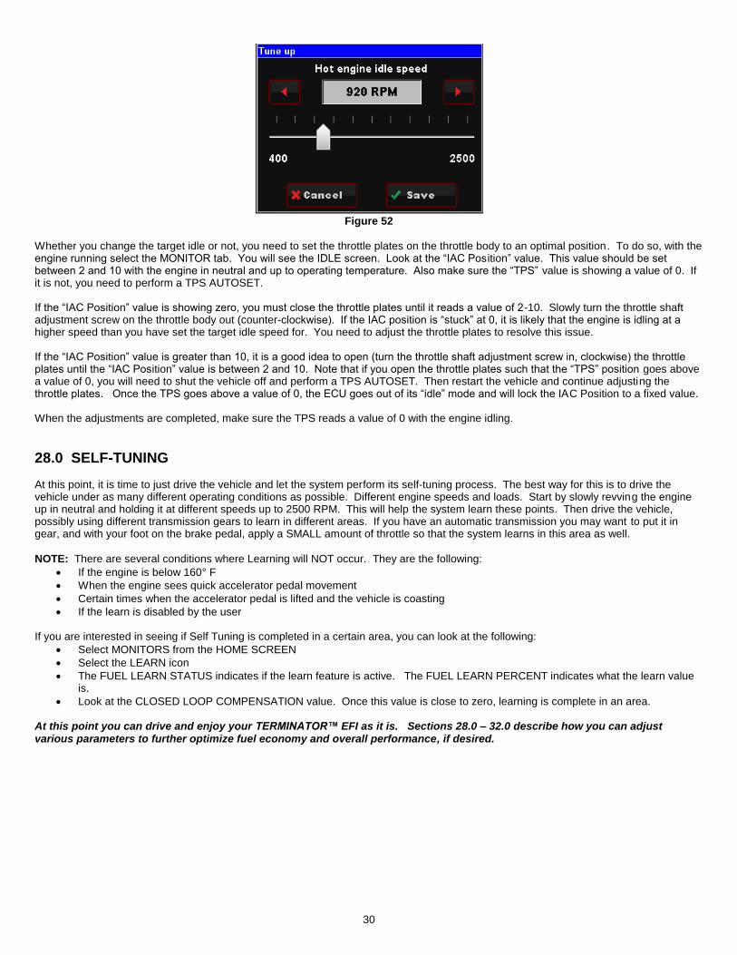
27.0 IDLE SETTING/THROTTLE PLATE SETTING Once the engine is up to operating temperature, the idle speed can be set to what is desired. From the HOME SCREEN, select the TUNING tab. Then select the BASIC and then BASIC IDLE. You can see what the target hot idle speed is set to. If you are happy with the current value, use the BACK or HOME button to exit. If you would like to change it, click on the IDLE SPEED. This brings up a screen to adjust the idle speed. Move the button left and right to adjust it. Click the button to save the new value or select CANCEL at the bottom to move out of this screen.
30
Figure 52
Whether you change the target idle or not, you need to set the throttle plates on the throttle body to an optimal position. To do so, with the engine running select the MONITOR tab. You will see the IDLE screen. Look at the “IAC Pos ition” value. This value should be set between 2 and 10 with the engine in neutral and up to operating temperature. Also make sure the “TPS” value is showing a value of 0. If it is not, you need to perform a TPS AUTOSET. If the “IAC Position” value is showing zero, you must close the throttle plates until it reads a value of 2-10. Slowly turn the throttle shaft adjustment screw on the throttle body out (counter-clockwise). If the IAC position is “stuck” at 0, it is likely that the engine is idling at a higher speed than you have set the target idle speed for. You need to adjust the throttle plates to resolve this issue. If the “IAC Position” value is greater than 10, it is a good idea to open (turn the throttle shaft adjustment screw in, clockwise) the throttle plates until the “IAC Position” value is between 2 and 10. Note that if you open the throttle plates such that the “TPS” position goes above a value of 0, you will need to shut the vehicle off and perform a TPS AUTOSET. Then restart the vehicle and continue adjusting the throttle plates. Once the TPS goes above a value of 0, the ECU goes out of its “idle” mode and will lock the IAC Position to a fixed value. When the adjustments are completed, make sure the TPS reads a value of 0 with the engine idling.
28.0 SELF-TUNING At this point, it is time to just drive the vehicle and let the system perform its self-tuning process. The best way for this is to drive the vehicle under as many different operating conditions as possible. Different engine speeds and loads. Start by slowly revving the engine up in neutral and holding it at different speeds up to 2500 RPM. This will help the system learn these points. Then drive the vehicle, possibly using different transmission gears to learn in different areas. If you have an automatic transmission you may want to put it in gear, and with your foot on the brake pedal, apply a SMALL amount of throttle so that the system learns in this area as well.
NOTE: There are several conditions where Learning will NOT occur. They are the following:
If the engine is below 160° F
When the engine sees quick accelerator pedal movement
Certain times when the accelerator pedal is lifted and the vehicle is coasting
If the learn is disabled by the user If you are interested in seeing if Self Tuning is completed in a certain area, you can look at the following:
Select MONITORS from the HOME SCREEN
Select the LEARN icon
The FUEL LEARN STATUS indicates if the learn feature is active. The FUEL LEARN PERCENT indicates what the learn value is.
Look at the CLOSED LOOP COMPENSATION value. Once this value is close to zero, learning is complete in an area. At this point you can drive and enjoy your TERMINATOR™ EFI as it is. Sections 28.0 – 32.0 describe how you can adjust various parameters to further optimize fuel economy and overall performance, if desired.

31
29.0 GAUGE SCREENS The display has a nice variety of pre-configured gauge screens and also allows the customization of them as well. There are also user- programmable caution and warning limits. The following reviews these areas.
29.1 Monitor Choose MONITOR from the HOME screen to access live telemetry and customizable gauge screen options.
Figure 53
29.1.1 Multi-Gauge
Sensors: Manifold Absolute Pressure (MAP), Coolant Temperature (CTS), Throttle Position (TPS), AFR Left, Engine RPM
(analog), Battery Voltage, Ignition Timing, Manifold Air Temperature (MAT), Fuel Pressure, Engine RPM (digital), and Fuel
Injector Duty Cycle.
Air/Fuel Ratio: AFR Left, Target AFR, AFR Right, Closed Loop Compensation, Fuel Learn, Closed Loop Status, Engine RPM
(analog), Learn Status, Fuel Injector Pulse Width, Engine RPM (digital), and Oil Pressure.
Outputs: Fan #1, Fan#2, AC Shutdown, CTS, Engine RPM (analog), IAC Position, AFR Left, Battery Voltage, Fuel Pressure,
Engine RPM (digital), Oil Pressure.
Drive by Wire: TPS, Pedal Position, TB Position, TB TPS #1, Engine RPM (analog), Pedal TPS1, TB TPS #2, Pedal TPS2,
Brake Pedal, Engine RPM (digital), MAP.
Transmission: Gear, Engine RPM (digital), Line Pressure, TCC Duty, Engine RPM (analog), TCC Lockup, Line Temp, Input
Shaft Speed, TPS, Speed, Fuel Economy.
Dash 1, 2, & 3: See the ‘Dash Setup’ section
Figure 54 – Sample of Multi-Gauge Screen

32
29.1.2 Monitors
Idle: Engine RPM, TPS, IAC Position, AFR Left, Ignition Timing
Learn: Fuel Learn Status, Fuel Learn Percent, Closed Loop Compensation, Target AFR, AFR Left
Closed Loop: Closed Loop Status, Closed Loop Compensation, Target AFR, AFR Left, Fuel Learn Status
Sensors: MAP, TPS, MAT, CTS, Battery Voltage
Fuel: Engine RPM, AFR Left, Injector Pulse Width, CL Comp, Injector Duty Cycle
Misc: Oil Pressure, Fuel Pressure, Fan #1 Status, Fan #2 Status, AC Shutdown Status
Drive by Wire: Gas Pedal Position, TB TPS #1, TB TPS #2, Pedal TPS #1, Pedal TPS #2, TB Position, Brake Pedal Position
Transmission: Gear, Speed, Line Pressure, Line Temperature, TCC Duty Cycle, TCC Lockup Status, Input Shaft Speed
Figure 55 Figure 56
Samples of Monitor Screens
29.1.3 Diagnostics Channels displayed are: AFR Left, AFR Right, MAP, TPS, MAT, CTS
Figure 57 – Sample Diagnostics Screen
30.0 Custom Setups
30.1 Dash Setup Up to three (3) Custom gauge layouts can be created on the 3.5 Touch Screen. Follow these steps to configure:
Step 1: Choose ‘Dash Setup’ from the Multi-Gauge screen (Figure 58).
Step 2: Choose the Dash number to be configured (Figure 59).

33
Figure 58 Figure 59
30.2 Channels Scaling Each HEFI channel displayed by the 3.5 Touch Screen can be configured to have caution and warning indicators. To do this, choose ‘Channel Scaling’ from the MONITOR menu. Cautions will display as Yellow and Warnings will display as RED when using the Mul ti-Gauge screens.
Figure 60 Figure 61
Figure 62 Figure 63
31.0 FILE SAVING/LOADING The following areas review the options located under the FILE selection. Access to any of these areas should not be necessary for normal use of your Terminator system.
31.1 File Choose FILE from the HOME screen to access ECU and 3.5 touch screen information. This is also where ECU logging and Global Folder (calibration file) transfer menus are located.

34
Figure 64
31.1.1 ECU Overview Information specific to the engine and ECU configuration is shown here, these include the name of the current global folder, transmission type, ignition input type, WBO2 type, throttle body type, fuel system type, and ECU firmware version. Note that this menu is view only – no information can be changed. Any changes to engine or transmission setup must be done through the TUNING or WIZARDS menu.
Figure 65 Figure 66
31.1.2 ECU Globals This menu will list any global folders that have been saved to the SD card. It will also allow you to download a global folder from the ECU to the SD card so that it may be opened on any Windows based PC with free Holley EFI software installed. Software may be downloaded at http://www.holley.com/data/TechService/Technical/Holley%20EFI%202.2.0.3%20Setup.zip
Figure 67 - Global Folders List Figure 68 - Global Folder Upload to ECU from SD Card

35
Figure 69 - Upload Status Screen Figure 70 - Global Folder Download to SD Card Status Screen
31.1.3 ECU Data Logging Holley HP and Dominator systems come standard with powerful data logging capabilities. Logging can be stopped and started via the 3.5 Handheld. The sampling rate is adjustable from 1 to 100 samples per second and can be changed by selecting ‘Setup’. Typically a high sampling rate is used for drag racing and a lower rate may be used for something such as road racing. Choosing ‘Files’ in the DATA LOGGING menu will display all logs contained within the ECU’s memory, from here any file may be saved to the SD card and viewed through the Holley EFI PC software.
Figure 71 Figure 72
31.1.4 ECU Hardware/Firmware (HW/FW) Use this menu to update ECU Firmware. Also includes ECU data including serial number, date code, firmware version, and profile number.
Figure 73 Figure 74

36
31.1.5 Local Setup Contains calibration options for the 3.5 Handheld: Touch Calibrate, Local Info, & Local Options.
Figure 75
31.1.5A Touch Calibrate The touch screen may be recalibrated by following the on screen prompts.
Figure 76
31.1.5B Local Info Displays device and firmware information for the 3.5 Handheld.
Figure 77
31.1.5C Local Options By selecting ‘Restore screens on startup’ the 3.5 Handheld will revert to the last screen used prior to powering off.
32.0 BASIC TUNING The TERMINATOR™ systems allow the user to perform some basic tuning changes to help optimize mileage, drivability, and performance. The tuning is split up into “Basic Tuning” and “Advanced Tuning”. The Basic Tuning allows changes to the Air/Fuel Ratio’s the engine runs at and changes to Ignition Timing if a GM HEI or Ford TFI is used. The Advanced Tuning is typically not needed, but allows changes to some items that are less commonly used, or require some careful understanding before changing. From the HOME SCREEN, select TUNING, and BASIC. There are six areas you can modify, BASIC FUEL, FUEL LEARN, BASIC IDLE, SPARK, DRIVE BY WIRE, and TRANSMISSION (with Drive by Wire and Transmission applying if applicable). These are reviewed below.

37
Figure 78
32.1 Basic Fuel Selecting BASIC FUEL brings up the following menu:
Figure 79
32.1.1 Target AFR Allows changes to the Target Air/Fuel ratio at idle, cruise, and wide open throttle. The following are typical values and some tuning notes.
Figure 80 Figure 81
Idle Air/Fuel Ratio – Typically between 13.5 and 15.0. Engines with larger cams may need a richer setting for smoothest idle. Cruise Air/Fuel Ratio – Typically between 13.5 and 15.5. Engines with larger cams may need a richer setting for smoothest
operation. Wide Open Throttle Air/Fuel Ratio (WOT) – Typically between 12.0 and 13.0. Running richer may reduce power. Running
leaner may reduce power or cause potential engine damage.
NOTE: The Target Air/Fuel setting between IDLE, CRUISE, and WOT is blended together automatically. Consequently, the air/fuel you see on the MONITOR screen, may not be exactly what you set for the settings. Changing these settings raises or lowers the “curve” of that specific area.
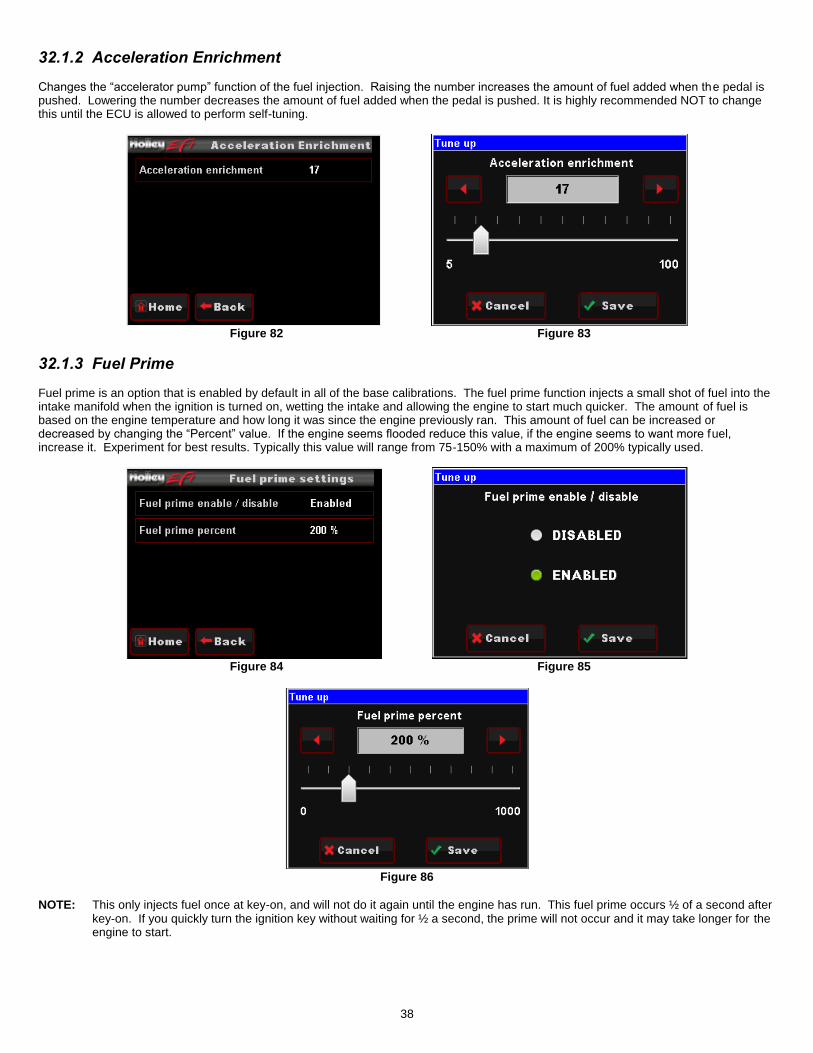
38
32.1.2 Acceleration Enrichment Changes the “accelerator pump” function of the fuel injection. Raising the number increases the amount of fuel added when the pedal is pushed. Lowering the number decreases the amount of fuel added when the pedal is pushed. It is highly recommended NOT to change this until the ECU is allowed to perform self-tuning.
Figure 82 Figure 83
32.1.3 Fuel Prime Fuel prime is an option that is enabled by default in all of the base calibrations. The fuel prime function injects a small shot of fuel into the intake manifold when the ignition is turned on, wetting the intake and allowing the engine to start much quicker. The amount of fuel is based on the engine temperature and how long it was since the engine previously ran. This amount of fuel can be increased or decreased by changing the “Percent” value. If the engine seems flooded reduce this value, if the engine seems to want more fuel, increase it. Experiment for best results. Typically this value will range from 75-150% with a maximum of 200% typically used.
Figure 84 Figure 85
Figure 86
NOTE: This only injects fuel once at key-on, and will not do it again until the engine has run. This fuel prime occurs ½ of a second after key-on. If you quickly turn the ignition key without waiting for ½ a second, the prime will not occur and it may take longer for the engine to start.

39
32.2 Fuel Learn
32.2.1 Learn Enable/Disable The LEARN Enable / Disable menu turns the Self Tuning “On” and “Off”. If enabled, self-tuning is performed. Learning should be enabled when an engine is just started and the tuning process is occurring. After the vehicle is driven under various operating conditions, and is running well, it is advised to disable learning, OR slow the Learn Speed to “Slow”.
32.2.2 Learn Speed This parameter adjusts how fast the learning process occurs. In the beginning with a new tune it should be set to “Fast”. After the vehicle is driven under various operating conditions, and is running well, it is advised to disable learning, OR slow the Learn Speed to “Slow”.
Figure 87 Figure 88
Figure 89
32.3 Basic Idle Selecting BASIC IDLE allows you to change the Target Hot Engine Idle Speed. This should be adjusted to your desired idle RPM. Values between 650-800 rpm are typical. Larger camshafts or aftermarket torque converters may require a slightly higher value to maintain proper idle quality while in gear.
Figure 90 Figure 91
Selecting IDLE allows you to change the Target Idle Speed.
IDLE SPEED: Adjust the idle speed to what is desired.

40
32.4 Spark
Figure 92 Figure 93
All Holley base tunes contain timing curves that will provide adequate engine operation, however the ignition timing at idle, cruise, and wide open throttle can be adjusted independently from each other to compensate for different engine combinations and geographical and climate extremes. The following are typical values for each:
Idle Timing – 18-34 degrees is typically used at idle. The larger the camshaft, the more timing is usually used.
Cruise Timing – 32-48 degrees is typically used when cruising for optimal fuel economy.
Wide Open Throttle Timing (WOT) – LSx applications typically don’t use more than 28 degrees at WOT. Older V8 engines are usually between 32-38 degrees.
NOTE: Too much timing can cause pre-ignition that can damage an engine. Be cautious when tuning.
NOTE: The actual timing between IDLE, CRUISE, and WOT is blended together automatically. Consequently, the timing you see on the MONITOR screen, may not be exactly what you set for these settings. Changing these settings raises or lowers the “curve” of that specific area.
32.5 Transmission NOTE: Caution must be used when modifying transmission parameters. Lowering line pressures too much can cause rapid
wear and damage to the transmission. The base calibrations provided should provide a safe base calibration. If the
transmission has very soft shifts or seems to slip, immediately stop to diagnose whether the problem is due to tuning
or mechanical issues.
Selecting TRANSMISSION brings up the following menu. There are five areas you can modify; SHIFTS, WOT SHIFTS, TCC PARAMS, TCC (UN)LOCK, and LINE PRESSURE. These are reviewed below.
32.5.1 Shifts Each Up-shift and Down-shift can be completely configured by selecting ‘Shifts’ from the transmission menu. Refer to section 18.1 (Making Adjustments) of this document for instructions on how to modify these curves. Upshift/Downshift Tuning Notes:
All Upshift points must occur at a higher speed than downshift. The touchscreen will give a warning and not allow this to occur if requested.
Although it can be programmed with the handheld, the ECU won’t allow a downshift to occur if it will over-rev the past the MAXIMUM RPM in the SYSTEM>TRANSMISSION>TRANS SETUP area.
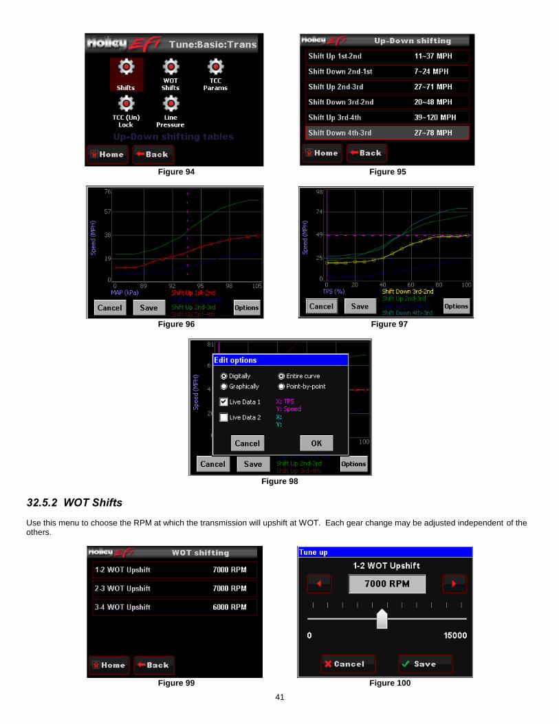
41
Figure 94 Figure 95
Figure 96 Figure 97
Figure 98
32.5.2 WOT Shifts Use this menu to choose the RPM at which the transmission will upshift at WOT. Each gear change may be adjusted independent of the others.
Figure 99 Figure 100
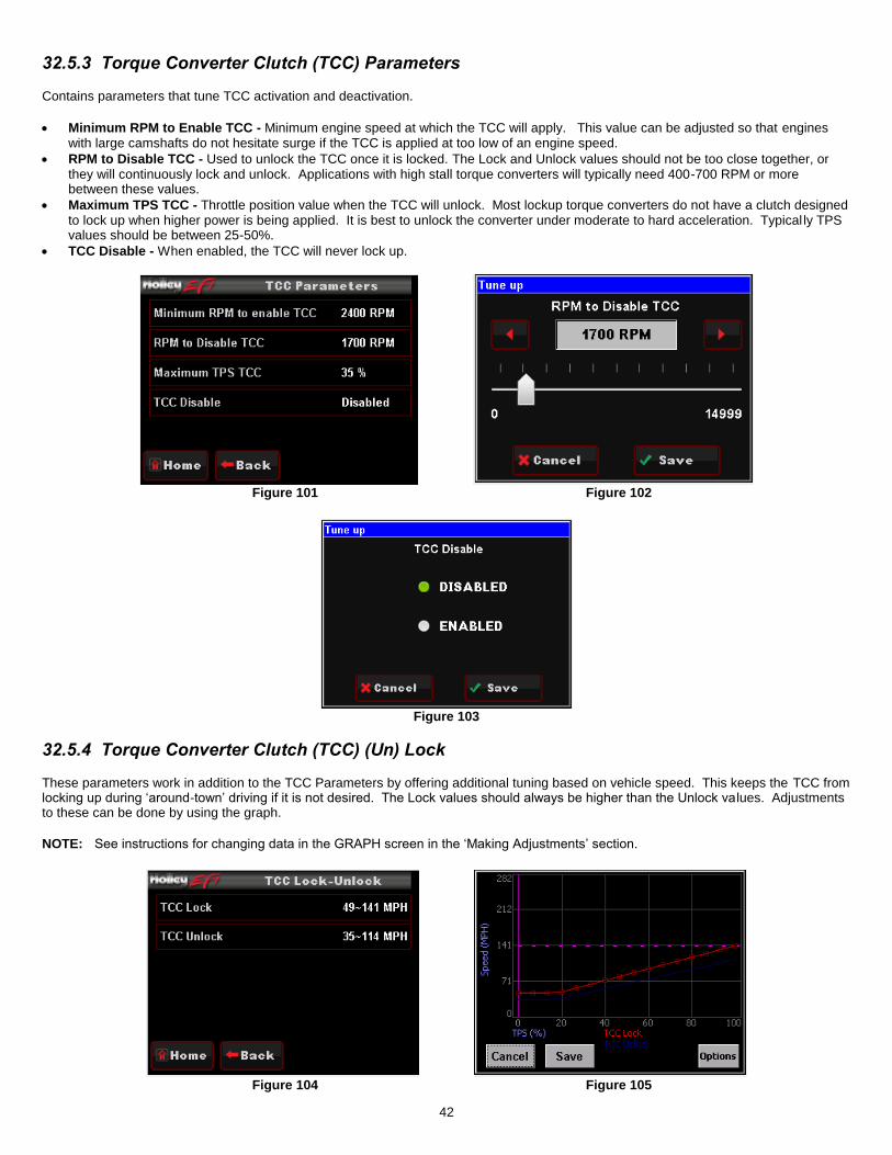
42
32.5.3 Torque Converter Clutch (TCC) Parameters Contains parameters that tune TCC activation and deactivation.
Minimum RPM to Enable TCC - Minimum engine speed at which the TCC will apply. This value can be adjusted so that engines with large camshafts do not hesitate surge if the TCC is applied at too low of an engine speed.
RPM to Disable TCC - Used to unlock the TCC once it is locked. The Lock and Unlock values should not be too close together, or they will continuously lock and unlock. Applications with high stall torque converters will typically need 400-700 RPM or more between these values.
Maximum TPS TCC - Throttle position value when the TCC will unlock. Most lockup torque converters do not have a clutch designed to lock up when higher power is being applied. It is best to unlock the converter under moderate to hard acceleration. Typical ly TPS values should be between 25-50%.
TCC Disable - When enabled, the TCC will never lock up.
Figure 101 Figure 102
Figure 103
32.5.4 Torque Converter Clutch (TCC) (Un) Lock These parameters work in addition to the TCC Parameters by offering additional tuning based on vehicle speed. This keeps the TCC from locking up during ‘around-town’ driving if it is not desired. The Lock values should always be higher than the Unlock va lues. Adjustments to these can be done by using the graph.
NOTE: See instructions for changing data in the GRAPH screen in the ‘Making Adjustments’ section.
Figure 104 Figure 105
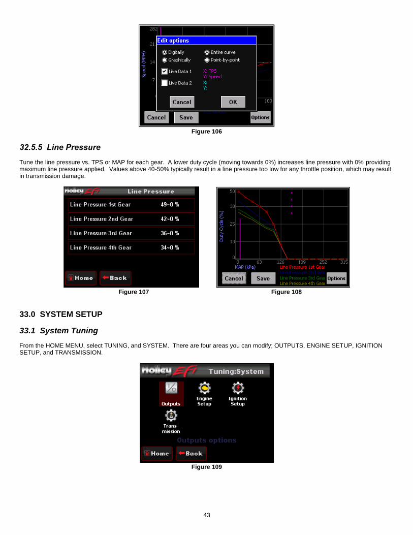
43
Figure 106
32.5.5 Line Pressure Tune the line pressure vs. TPS or MAP for each gear. A lower duty cycle (moving towards 0%) increases line pressure with 0% providing maximum line pressure applied. Values above 40-50% typically result in a line pressure too low for any throttle position, which may result in transmission damage.
Figure 107 Figure 108
33.0 SYSTEM SETUP
33.1 System Tuning From the HOME MENU, select TUNING, and SYSTEM. There are four areas you can modify; OUTPUTS, ENGINE SETUP, IGNITION SETUP, and TRANSMISSION.
Figure 109

44
33.1.1 Outputs The OUTPUT screen allows for the Fan #1 and Fan #2 ON and OFF temperatures to be adjusted. The ON temp needs to always be a higher value than the OFF temp. Use a difference of at least 5 degrees so they aren’t cycling excessively. In Terminator Ki ts these are ground outputs that should be wired to trigger the fan relays. NEVER wire them directly to the fans! The AC Disable value is a TPS value above which a 12 volt output is sent out to deactivate the air conditioning compressor at wide open throttle.
Figure 110 Figure 111
Figure 112
33.1.2 Engine Setup These parameters should all be properly pre-set when you went through the Wizard process. If you change something on your engine, or run a different system fuel pressure or injector size, they can be edited here
Figure 113
Fuel Injector Flow: Adjust fuel flow injector ratings to match what is installed on the engine
Actual System Fuel Pressure: Enter the actual fuel system pressure for accurate fuel map & logging data.
Wide Band O2 Sensor Type: Selects the type of wide band oxygen sensor used. If the software selection does not match the sensor being used damage to the WBO2 sensor will occur.
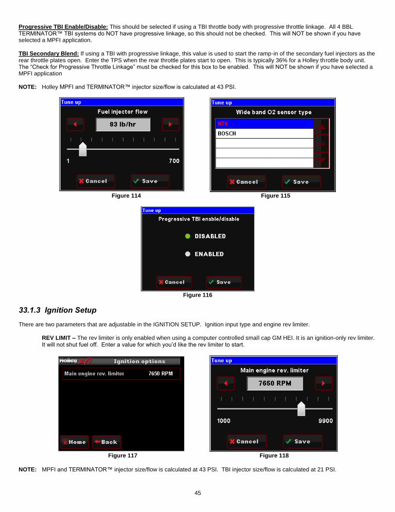
45
Progressive TBI Enable/Disable: This should be selected if using a TBI throttle body with progressive throttle linkage. All 4 BBL TERMINATOR™ TBI systems do NOT have progressive linkage, so this should not be checked. This will NOT be shown if you have selected a MPFI application.
TBI Secondary Blend: If using a TBI with progressive linkage, this value is used to start the ramp-in of the secondary fuel injectors as the rear throttle plates open. Enter the TPS when the rear throttle plates start to open. This is typically 36% for a Holley throttle body unit. The “Check for Progressive Throttle Linkage” must be checked for this box to be enabled. This will NOT be shown if you have selected a MPFI application
NOTE: Holley MPFI and TERMINATOR™ injector size/flow is calculated at 43 PSI.
Figure 114 Figure 115
Figure 116
33.1.3 Ignition Setup There are two parameters that are adjustable in the IGNITION SETUP. Ignition input type and engine rev limiter.
REV LIMIT – The rev limiter is only enabled when using a computer controlled small cap GM HEI. It is an ignition-only rev limiter. It will not shut fuel off. Enter a value for which you’d like the rev limiter to start.
Figure 117 Figure 118
NOTE: MPFI and TERMINATOR™ injector size/flow is calculated at 43 PSI. TBI injector size/flow is calculated at 21 PSI.
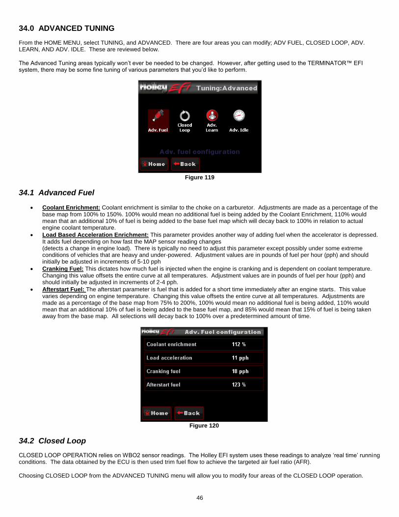
46
34.0 ADVANCED TUNING From the HOME MENU, select TUNING, and ADVANCED. There are four areas you can modify; ADV FUEL, CLOSED LOOP, ADV. LEARN, AND ADV. IDLE. These are reviewed below.
The Advanced Tuning areas typically won’t ever be needed to be changed. However, after getting used to the TERMINATOR™ EFI system, there may be some fine tuning of various parameters that you’d like to perform.
Figure 119
34.1 Advanced Fuel
Coolant Enrichment: Coolant enrichment is similar to the choke on a carburetor. Adjustments are made as a percentage of the base map from 100% to 150%. 100% would mean no additional fuel is being added by the Coolant Enrichment, 110% would mean that an additional 10% of fuel is being added to the base fuel map which will decay back to 100% in relation to actual engine coolant temperature.
Load Based Acceleration Enrichment: This parameter provides another way of adding fuel when the accelerator is depressed. It adds fuel depending on how fast the MAP sensor reading changes (detects a change in engine load). There is typically no need to adjust this parameter except possibly under some extreme conditions of vehicles that are heavy and under-powered. Adjustment values are in pounds of fuel per hour (pph) and should initially be adjusted in increments of 5-10 pph
Cranking Fuel: This dictates how much fuel is injected when the engine is cranking and is dependent on coolant temperature. Changing this value offsets the entire curve at all temperatures. Adjustment values are in pounds of fuel per hour (pph) and should initially be adjusted in increments of 2-4 pph.
Afterstart Fuel: The afterstart parameter is fuel that is added for a short time immediately after an engine starts. This value varies depending on engine temperature. Changing this value offsets the entire curve at all temperatures. Adjustments are made as a percentage of the base map from 75% to 200%, 100% would mean no additional fuel is being added, 110% would mean that an additional 10% of fuel is being added to the base fuel map, and 85% would mean that 15% of fuel is being taken away from the base map. All selections will decay back to 100% over a predetermined amount of time.
Figure 120
34.2 Closed Loop CLOSED LOOP OPERATION relies on WBO2 sensor readings. The Holley EFI system uses these readings to analyze ‘real time’ running conditions. The data obtained by the ECU is then used trim fuel flow to achieve the targeted air fuel ratio (AFR).
Choosing CLOSED LOOP from the ADVANCED TUNING menu will allow you to modify four areas of the CLOSED LOOP operation.

47
Figure 121
Closed Loop Enable/Disable: This menu enables or disables closed loop operation. There is typically no reason to turn off
closed loop operation unless you suspect an oxygen sensor problem and want to disable the sensor. Note: Self-Tuning requires closed loop operation to function.
Closed Loop Limit: The maximum percentage the ECU is allowed to deviate (+/-) from the base fuel calibration in order to maintain the commanded target air fuel ratio. This is set to 100% by default and under most circumstances should not need to be changed.
Closed Loop Speed: This is the “speed” (gain) at which closed loop operation occurs. This can be set to five levels, 1, 2, 3, 4, or 5. 3 is the base setting and should be good for most applications. 4 or 5 is typically not used as the closed loop speed may be too excessive for certain applications. If the oxygen sensor is installed far back in the exhaust (more than 1 foot back from the collector in long tube headers), a value of 1 or 2 may be needed.
Open Loop Below This: This setting is usually zero. If an extremely large camshaft is used (specs only typically found on race camshafts), the overlap sometimes causes a “false lean” reading at low RPM. In these cases, it may be required to put in a va lue of 1500-2000 RPM so the system operates open loop below this RPM setting.
Figure 122 Figure 123
Figure 124 Figure 125
34.3 Advanced Learn Choosing ADVANCED LEARN will allow you to modify the LEARN COMPENSATION LIMITS. This value is set to 100% by default, and should remain there until ample driving time and tuning has occurred. The LEARN COMPENSATION LIMIT is a parameter that ECU is allowed to work within when making changes to the fuel map based upon CLOSED LOOP operation. Unlike the CLOSED LOOP LIMIT which is a set parameter for commanded changes to actual fuel flow based upon the O2 sensor reading, LEARN COMPENSATION LIMITS are the percentage of change that is allowed to actually be saved as a modifier to the fuel map.

48
Figure 126 Figure 127
34.3 Advanced Idle The ADVANCED IDLE parameters adjust specific characteristics of how the idle air control motor functions on engine decel and startup.
Selecting ADVANCED IDLE brings up the following menu:
Figure 128
34.3.1 IAC Rampdown The Idle Air Control (IAC) motor is a stepper motor located in the throttle body that controls the idle speed of the engine by metering air. It also operates during engine cranking and when the engine returns back to idle. The following settings can adjust how that functions. The IAC moves from a position of 0% (fully closed, no air added) to 100% (fully open, maximum air flow).
NOTE: Contact Holley Tech Support if you have any questions regarding IAC settings. Selecting IAC RAMPDOWN brings up the following menu with four choices, IAC HOLD POSITION, IAC RAMP DECAY, IAC RAMP START, and IAC KICK. These are reviewed below:
IAC Hold Position: This is the position the IAC motor will “hold” or “freeze” at when the TPS moves above idle (when TPS becomes greater than 0%). If it is too high, the engine RPM will “hang” and not return to idle.
IAC Ramp Decay: This is the time (in seconds) it takes for the IAC to decay from the “IAC Hold Position” back to a “0%” position. It is a linear decay.
IAC Ramp Start (RPM above idle): This value is the RPM added to the target idle speed that the IAC will automatically start to ramp back down to idle. If this is too low, the engine RPM will “hang” and not return to idle.
IAC Kick: The IAC Kick provides a temporary increase in IAC position to keep engine the RPM from dropping. Typically this is used in conjunction with an A/C system keep the engine speed from ‘dipping’ as the compressor cycles on and off.

49
Figure 129
34.3.2 IAC Speed This menu is used to select the type of IAC motor application that is being used. This selection drives the background parameters that control the IAC motor. These parameters have been fine tuned for each of these applications, eliminating the need for the user to perform further modifications
Figure 130 Figure 131
34.3.3 IAC Startup These parameters control the position of the IAC when the engine is cranking and immediately after it starts.
Selecting IAC STARTUP brings up the following menu with three choices, IAC PARKED POSITION (CRANKING), IAC STARTUP HOLD TIME, and IAC STARTUP DECAY TIME.
IAC Parked Position (Cranking): This is the position the IAC motor will be at during cranking and immediately after the engine starts. If it is too high, the engine will be at too high of an RPM once it starts. Too low and poor starting will result. Note that this is a temperature based table. The percentage value changed in the handheld offsets this entire curve.
IAC Startup Hold Time: This is the amount of time that the IAC will remain at the “IAC Parked Position”.
IAC Startup Decay Time: This is the amount of time for the IAC to decay from the “IAC Parked Position” back to its “Target Idle” position. It is a linear decay.

50
Figure 132
34.3.4 Idle Spark Idle spark is a feature active only when the ECU is controlling timing. When enabled, the ECU modifies commanded timing at idle to help maintain the target idle speed.
Figure 133 Figure 134
NOTE: This feature should be disabled when checking base timing with a timing light! If not disabled rev the engine to approximately
2000 RPM when syncing timing.
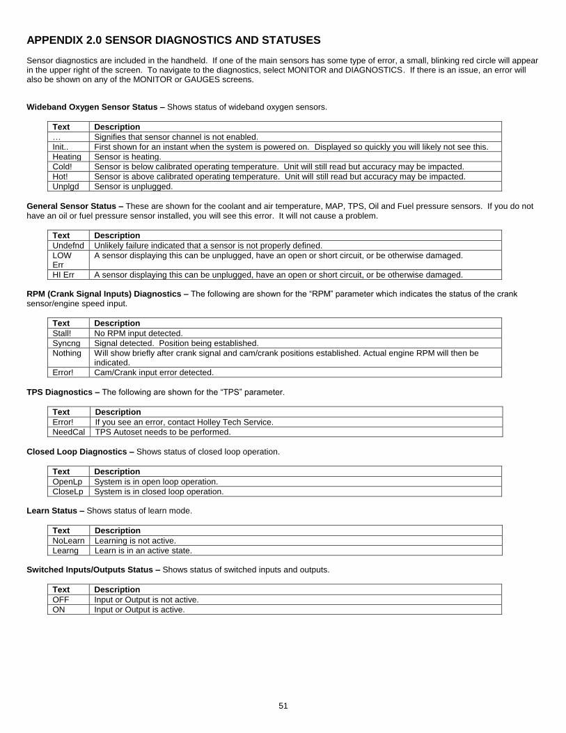
51
APPENDIX 2.0 SENSOR DIAGNOSTICS AND STATUSES Sensor diagnostics are included in the handheld. If one of the main sensors has some type of error, a small, blinking red circle will appear in the upper right of the screen. To navigate to the diagnostics, select MONITOR and DIAGNOSTICS. If there is an issue, an error will also be shown on any of the MONITOR or GAUGES screens.
Wideband Oxygen Sensor Status – Shows status of wideband oxygen sensors.
Text Description
… Signifies that sensor channel is not enabled.
Init.. First shown for an instant when the system is powered on. Displayed so quickly you will likely not see this.
Heating Sensor is heating.
Cold! Sensor is below calibrated operating temperature. Unit will still read but accuracy may be impacted.
Hot! Sensor is above calibrated operating temperature. Unit will still read but accuracy may be impacted.
Unplgd Sensor is unplugged.
General Sensor Status – These are shown for the coolant and air temperature, MAP, TPS, Oil and Fuel pressure sensors. If you do not have an oil or fuel pressure sensor installed, you will see this error. It will not cause a problem.
Text Description
Undefnd Unlikely failure indicated that a sensor is not properly defined.
LOW Err
A sensor displaying this can be unplugged, have an open or short circuit, or be otherwise damaged.
HI Err A sensor displaying this can be unplugged, have an open or short circuit, or be otherwise damaged.
RPM (Crank Signal Inputs) Diagnostics – The following are shown for the “RPM” parameter which indicates the status of the crank sensor/engine speed input.
Text Description
Stall! No RPM input detected.
Syncng Signal detected. Position being established.
Nothing Will show briefly after crank signal and cam/crank positions established. Actual engine RPM will then be indicated.
Error! Cam/Crank input error detected.
TPS Diagnostics – The following are shown for the “TPS” parameter.
Text Description
Error! If you see an error, contact Holley Tech Service.
NeedCal TPS Autoset needs to be performed.
Closed Loop Diagnostics – Shows status of closed loop operation.
Text Description
OpenLp System is in open loop operation.
CloseLp System is in closed loop operation.
Learn Status – Shows status of learn mode.
Text Description
NoLearn Learning is not active.
Learng Learn is in an active state.
Switched Inputs/Outputs Status – Shows status of switched inputs and outputs.
Text Description
OFF Input or Output is not active.
ON Input or Output is active.

52
Figure 135
Figure 136

53
Figure 137
Figure 138

54
Figure 139
Figure 140
Holley Technical Support: 270-781-9741
© 2015 Holley Performance Products, Inc. All rights reserved.
199R10772
Date: 5-9-16