4” & 6” High Clearance Suspension Systembds-suspension.com/instructions/022624.pdf · 4” &...
19
4” & 6” High Clearance Suspension System Dodge Ram 1500 4WD | 2012-2017 Rev. 020918 Part#: 022624, 022402 491 W. Garfield Ave., Coldwater, MI 49036 . Phone: 517-279-2135 E-mail: [email protected]
Transcript of 4” & 6” High Clearance Suspension Systembds-suspension.com/instructions/022624.pdf · 4” &...
4” & 6” High Clearance Suspension System
Dodge Ram 1500 4WD | 2012-2017
Rev. 020918
Part#: 022624, 022402
491 W. Garfield Ave., Coldwater, MI 49036 . Phone: 517-279-2135E-mail: [email protected]

2 | 022624, 022402
Read And Understand All Instructions And Warnings Prior To Installation Of System And Operation Of Vehicle.
BEFORE YOU STARTBDS Suspension Co. recommends this system be installed by a professional technician. In addition to these instructions, professional knowledge of disassembly/ reassembly procedures and post installation checks must be known.
FOR YOUR SAFETYCertain BDS Suspension products are intended to improve off-road performance. Modifying your vehicle for off-road use may result in the vehicle handling differently than a factory equipped vehicle. Extreme care must be used to prevent loss of control or vehicle rollover. Failure to drive your modified vehicle safely may result in serious injury or death. BDS Suspension Co. does not recommend the combined use of suspension lifts, body lifts, or other lifting devices. You should never operate your modified vehicle under the influence of alcohol or drugs. Always drive your modified vehicle at reduced speeds to ensure your ability to control your vehicle under all driving conditions. Always wear your seat belt.
BEFORE INSTALLATION• Special literature required: OE Service Manual for model/year of vehicle.
Refer to manual for proper disassembly/reassembly procedures of OE and related components.
• Adhere to recommendations when replacement fasteners, retainers and keepers are called out in the OE manual.
• Larger rim and tire combinations may increase leverage on suspension, steering, and related components. When selecting combinations larger than OE, consider the additional stress you could be inducing on the OE and related components.
• Post suspension system vehicles may experience drive line vibrations. Angles may require tuning, slider on shaft may require replacement, shafts may need to be lengthened or trued, and U-joints may need to be replaced.
• Secure and properly block vehicle prior to installation of BDS Suspension components. Always wear safety glasses when using power tools.
• If installation is to be performed without a hoist, BDS Suspension Co. recommends rear alterations first.
• Due to payload options and initial ride height variances, the amount of lift is a base figure. Final ride height dimensions may vary in accordance to original vehicle attitude. Always measure the attitude prior to beginning installation.
Your truck is about to be fitted with the best suspension system on the market today. That means you will be driving the baddest looking truck in the neighborhood, and you’ll have the warranty to ensure that it stays that way for years to come.
Thank you for choosing BDS Suspension!
Tires Wheel Size Backspacing
37” x12.50” 17x8 4.5”
37” x12.50” 18x9 5”
37” x12.50” 20x9 5”
BEFORE YOU DRIVECheck all fasteners for proper torque. Check to ensure for adequate clearance between all rotating, mobile, fixed, and heated members. Verify clearance between exhaust and brake lines, fuel lines, fuel tank, floor boards and wiring harness. Check steering gear for clearance. Test and inspect brake system.
Perform steering sweep to ensure front brake hoses have adequate slack and do not contact any rotating, mobile or heated members. Inspect rear brake hoses at full extension for adequate slack. Failure to perform hose check/ replacement may result in component failure. Longer replacement hoses, if needed can be purchased from a local parts supplier.
Perform head light check and adjustment.
Re-torque all fasteners after 500 miles. Always inspect fasteners and components during routine servicing.
Stock 17” wheels cannot be re-installed. Stock 20” can only be re-installed with the factory tire.

022624, 022402 | 3
022620 & 022621 Box Kit (2012 models only)
Part # Qty Description
02230 1 Steering Knuckle - DS
02231 1 Steering Knuckle - PS
44066 2 Tie Rod End022630 & 022631 Box Kit (13-17 models only)
Part # Qty Description
02230 1 Steering Knuckle - DS
02231 1 Steering Knuckle - PS
20277 2 Tie Rod End
022625 Box Kit
Part # Qty Description
01295B 1 HC Front Crossmember
02389B 1 Diff.Drop Bracket - PS
02278B 1 Diff. Drop Bracket - DS Front
02277B 1 Diff. Drop Bracket - DS Rear
01236B 1 Diff. Drop Bracket - DS Outer Front
6865833 1 CV Boot Clamp
022402 & 022624 Box Kit
Part # Qty Description
02242 1 Front Drive Shaft Spacer
01298B 1 HC Diff Skid Plate
02002ZP 4 M18-2.5 x 150 Class 10.9 Bolt
N18MPT 4 M18 x 2.5 Prevailing Torque Nut
01264 8 Square Washer
01296B 1 HC Rear Crossmember
02281 1 Front Brake Bracket (022402 only)
02282 1 Front Brake Bracket (022402 only)
768 1 Bolt Pack (022402 only)
099000 4 11.5in Nylon Cable Tie
02267B 2 4in Strut Spacer (022402 only)
911114 2 Sway Bar Link Extension
117300006 4 Large Stem Washer
01499 2 1/4in Spacer
342701 1 Loctite - 1ml
22531 2 Front Brake Line (022624 only)
5188 2 Snap In Brake Line Clip (022624 only)CCW-03-050 4 Crush Washer (022624 only)
01274 2 Brake Line Bracket (022624 only)
01267B 2 6in Strut Spacer (022624 only)
022309/022509 Box Kit (09-12 Models Only)
Part # Qty Description
See instructions located in box kit
022402 & 022624 Box Kit
660 1 Bolt Pack - Diff Hardware3 12mm-1.75 x 30mm bolt
2 12mm-1.75 x 40mm bolt
4
2
12mm-1.75 x 55mm bolt
12mm-1.75 x 60mm bolt
13 12mm flat washer
4 12mm-1.75 prevailing torque nut
3 1/2"-13 x 1-1/2" bolt
4 1/2"-13 X 1-1/4" bolt
3 1/2"-13 prevailing torque nut
10 1/2" SAE thru-hardened washer
662 1 Bolt Pack- Main Hardware2 1/4"-20 x 1/2" bolt
2 1/4"-20 prevailing torque nut
4 1/4" SAE washer
2 Wire Clip
6 10mm-1.50 Prevailing torque nut
6 10mm flat washer
2 1/2"-13 x 1-1/4" bolt
2 1/2"-13 prevailing torque nut
4 1/2" SAE flat washer
2 7/16"-14 Nylock nut
663 1 Bolt Pack - Driveshaft Spacer2 12mm-1.75mm x 45mm bolt
2 12mm flat washer

4 | 022624, 022402
01295FRONT CROSSMEMBER
RAM 1500 FRONT BOX KIT COMPONENTS
01296REAR CROSSMEMBER
02277DRV - REAR DIFF BRKT
02278DRV - INNER DIFF BRKT
01236DRV - OUTTER DIFF BRKT
02242DRIVE SHAFT SPACER
01298DIFF SKID PLATE
01264CAM WASHER
01267 - 6" STRUT SPACER or02267 - 4" STRUT SPACER
02281-02282BRAKELINE RELOCATION
BRKT - 4" KIT ONLY
01278PRELOAD SPACER
(INCLUDED IN REAR BOX KIT)
02389PASS - REAR DIFF BRKT
117300006CUP WASHER
911114SWAY BAR LINK
014991/4" DIFF SPACER
01274REPLACEMENT BRAKELINE
BRACKET - 6" KIT ONLY

022624, 022402 | 5
PRE-INSTALLATION MEASUREMENTS
Measure from the center of the wheel up to the bottom edge of the wheel opening
LF______ RF______ LR______ RR______
FRONT INSTALLATION1. Park the vehicle on a clean, flat surface and block the rear wheels for safety.
2. Raise the front of the vehicle and support with jack stands under the frame rails.
3. Remove the wheels.
4. Disconnect the sway bar links from the sway bar. Leave them attached to the lower control arm. (Fig 1).
FIGURE 1
5. Remove and discard the OE front skid plate, if equipped.
6. Disconnect the tie rod ends from the steering knuckles. Remove and retain the mounting nuts. Use the appropriate puller to separate the tie rod end from the steering knuckle. Take care not to damage the tie rod end.
7. Disconnect the ABS brake line at the frame. Remove it from any retaining clips.
TROUBLESHOOTING INFORMATION FOR YOUR VEHICLE1. These trucks vary from 1”-3” tail high from the factory. Measure your vehicle and install the correct
rear box kit for your desired stance.
2. The rack and pinion steering system is extremely sensitive to an out of round or out of balance tire/wheel. The larger the tire and the less backspacing, the more sensitive the system becomes, causing minor steering wheel shimmy.
3. On some vehicles an exhaust modification will be required to clear the front driveshaft in its new, lower position.
4. Not recommended for AWD models
5. Will not fit adjustable air suspension equipped models.
6. 6” systems not recommend for TRX models due to additional lift height produced.

6 | 022624, 022402
8. Steps 9-14 are for 6 inch kit with replacement brakelines only: Steps 15-18 are for 4 inch kit, which includes brakeline drop brackets. If installing optional brakelines - follow steps 9-14.
9. Disconnect the driver’s side front brake hose from the caliper. Retain the banjo bolt and discard the crush washers.
10. 6 inch kit only: Disconnect the hard line from the brake hose fitting at the frame. Remove the hose fitting retaining bolt and remove the hose from the vehicle. Retain the hose fitting mounting bolt.
11. 6 inch kit only: Attach the provided brake line relocation bracket (01274) to the frame where the original line mounted. Fasten the bracket with the OE fitting bolt through the original threaded hole and the corresponding small hole in the new bracket (Fig 2a). Align the other mounting hole in the bracket with the brake line hole in the frame and fasten with a ½” x 1-1/4” bolt, nut and ½” SAE washers (BP #662). Torque the OE bolt to 10 ft-lbs and the ½” bolt to 50 ft-lbs. Note: The third hole in the bracket should be hanging out past the edge of the frame.
FIGURE 2A
12. 6 inch kit only: Route the new stainless steel brake line though the relocation bracket and attach it to the hard line. Tighten the fitting securely. Fasten the line to the bracket with the provided retaining clip.
13. 6 inch kit only: Attach the opposite end of the new brake line to the caliper with the OE banjo bolt and one new crush washer on each side of the fitting. Torque the banjo bolt to 18 ft-lbs.
14. 6 inch kit only: Repeat brake line installation on the passenger’s side of the vehicle.
15. 4 inch kit only: Disconnect the brakeline hardware from the strut tower and pull the brakeline through the mount. Cut a slot to allow the brakeline to be removed from the frame. If you do not wish to cut on the coil bucket, the line can be disconnected and reconnected after it is removed from the frame. If the line is disconnected the brakes must be bled at the end of the installation. (Fig 2b)

022624, 022402 | 7
FIGURE 2B
16. 4 inch kit only: Attach the provided brake line relocation bracket to the frame where the original line mounted. The brakeline bracket will offset towards the rear of the vehicle. Torque the factory bolt to 10 ft-lbs and the ½” bolt to 50 ft-lbs.
17. 4 inch kit only: Carefully reform the hardline to gain additional length. Attach to the relocation bracket with 1/4” hardware (bolt pack #768). (Fig 2c)
FIGURE 2C
18. 4 inch kit only: Repeat brake line relocation bracket installation on the passenger’s side of the vehicle
19. Remove the brake caliper anchor bracket bolts and pull the caliper free from the steering knuckle and rotor. Hang the caliper securely out of the way. Retain caliper mounting hardware. Remove the brake rotor from the hub.
Do not allow the brake caliper to hang from the brake hose.
20. Remove the hub axle nut. Retain nut.
21. Loosen but do not remove the lower control arm bolts.
8 | 022624, 022402
22. Disconnect the CV axles from the differential by carefully prying CV out at the differential to disengage the internal retaining clip. Pry the shaft out just enough to release the clip and leave the axle on the differential at this time.
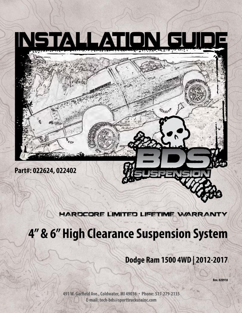
23. Support the lower control arm with a hydraulic jack. Remove the three strut-to-frame mounting nuts (Fig 3).
DO NOT loosen the middle strut nut.
FIGURE 3
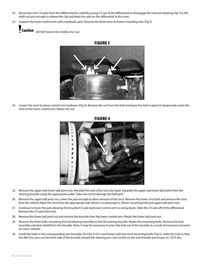
24. Loosen the strut-to-lower control arm hardware (Fig 4). Remove the nut from the bolt and leave the bolt in place to temporarily retain the strut to the lower control arm. Retain the nut.
FIGURE 4
25. Remove the upper and lower ball joint nuts. Reinstall the nuts a few turns by hand. Separate the upper and lower ball joints from the steering knuckle using the appropriate puller. Take care not to damage the ball joint.
26. Remove the upper ball joint nut. Lower the jack enough to allow removal of the strut. Remove the lower strut bolt and remove the strut from the vehicle. Mark the strut from the appropriate side (driver’s or passenger’s). Retain mounting bolt and upper ball joint nuts.
27. Continue to lower the jack allowing the knuckle/CV axle and lower control arm to swing down. Slide the CV axle off of the differential. Remove the CV axle from hub.
28. Remove the lower ball joint nut and remove the knuckle from the lower control arm. Retain the lower ball joint nut.
29. Remove the three bolts mounting the hub bearing assembly to the OE steering knuckle. Retain the mounting bolts. Remove the hub assembly and dust shield from the knuckle. Note: It may be necessary to press the hub out of the knuckle as a result of excessive corrosion on some vehicles.
30. Install the hubs in the corresponding new knuckles (01230, 01231) and fasten with the stock mounting bolts (Fig 5). Index the hub so that the ABS line runs out the front side of the knuckle toward the steering arm. Use Loctite on the bolt threads and torque to 125 ft-lbs.

022624, 022402 | 9
FIGURE 5
31. Remove the lower control arms from the frame. Retain hardware.
32. Make indexing marks on the front drive shaft and differential input flange for realignment later. Remove the four bolts and disconnect the drive shaft from the differential. Support the driveshaft to keep the CV boot from binding. Discard mounting bolts.
Failure to support the driveshaft can lead to pinching the rubber boot at the CV joint which can damage the seal causing a leak and premature wear on the joint.
33. Remove the four bolts mounting the OE rear crossmember to the frame rails and remove the crossmember from the vehicle. Discard the crossmember and the hardware.
34. Using a jack, support the differential. Loosen and remove the two forward-most differential mounting bolts on the driver’s side (Fig 6A). Loosen but do not remove the three rear driver’s side bolts (Fig 7 ) and the two passenger’s side bolts (Fig 8A). On the passenger’s side, if equipped, remove the differential actuator cable bracket. It will not be reused. DIESEL MODELS - DRV Side: Diesel model vehicles have tighter clearance between the motor and front driver’s side differential mount. It may be easier to remove the entire mount with the differential. If so, support the motor and remove the 2 motor mount bracket to differential bracket bolts as well as the main motor mount bolt (Fig 6B). Once the differential is removed, remove the bracket from the differential (Fig 6C) and reinstall in the vehicle and tighten hardware. DIESEL MODELS - PASS Side: There is a harmonic dampener attached to the passenger’s side differential mount. Remove with the differential and save (Fig 8B).
FIGURE 6A

10 | 022624, 022402
FIGURE 6B
FIGURE 6C
FIGURE 7
FIGURE 8A
FIGURE 8B
35. With the differential securely supported, remove the remaining bolts and lower the differential from the vehicle.

022624, 022402 | 11
36. The driver’s side rear lower control arm pocket must be trimmed to provide clearance for the differential in its lowered position. Measure inward from the inside edge of the alignment cam slot 1-3/4” and mark. Repeat on the opposite side of the pocket. Make a continuous line connecting the two marks over the top edge of the pocket. Trim the pocket on the line with a sawzall or cut off wheel. Paint any exposed metal to prevent corrosion (Fig 9).
FIGURE 9
1-3/4"
37. Install the provided passenger’s side differential drop bracket (02389B) to the original frame mount with OE hardware. The brackets should be installed offset forward as shown (Fig 10). Leave hardware loose.
FIGURE 10

12 | 022624, 022402
38. Install the two front driver’s side differential drop brackets so that the bracket with the small offset (01236) is toward the outside of the vehicle (offsetting out) and the one with the bigger offset (02278) is on the inside (offsetting in). The brackets should taper down in height as they go toward the rear of the vehicle (for correction of the pinion angle). Fasten the brackets to the frame with two 12mm x 40mm bolts and washers into the factory threaded holes (BP #660). Leave hardware loose. (Fig. 11a / b)
FIGURE 11A
FIGURE 11B
1/4" SPACER
39. Install the driver’s side rear differential drop bracket (01238) to the frame with three 1/2” x 1-1/2” bolts and ½” SAE washers (BP #660). (Fig. 12) The bracket will have the gusset plate towards the front of the vehicle. Leave hardware loose.

022624, 022402 | 13
FIGURE 12A
FIGURE 12B
FIGURE 12C
40. Using a jack (and an assistant to aid in balancing) raise the differential up to the new brackets.
41. Attach the differential to the driver’s side front bracket and Passenger’s side bracket with 12mm x 55mm bolts, nuts and washers (BP #660), the drivers side brackets shown in figure 11 will require 1/4” spacers. Attach the drivers side rear bracket to the differential with 12mm x 30mm bolts and washers (BP #660). Leave all differential hardware loose. DIESEL MODELS: When attaching the differential to the passenger’s side drop bracket, reinstall the harmonic dampener and use the (2) 12mm x 60mm bolts provided (BP 660) in place of the 12mm x 55mm bolts (Fig 12C).
42. Torque all 14 differential mounting bolts. Torque the ½” hardware to 65 ft-lbs and the 12mm hardware to 50 ft-lbs.
43. Locate the front differential wiring harness. Remove from factory clips to give enough slack to reach the differential. Reattach to differential and tie up extra slack with provided zip ties.
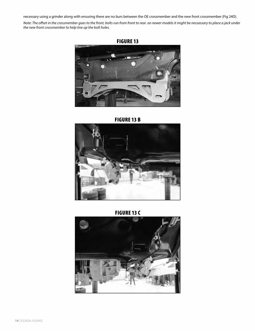
44. Install the new front crossmember (01295) in the OE front lower control arm pockets (Fig 24A) and loosely fasten with the provided 18mm x 150mm bolts, nuts in conjunction with the provided rectangle cam slot washers (01264). On newer models check for clearance between the new front crossmember (01295) and the OE front lower control arm pockets, trim the control arm pockets (Fig 24B and Fig 24C) if
14 | 022624, 022402
necessary using a grinder along with ensuring there are no burs between the OE crossmember and the new front crossmember (Fig 24D).
Note: The offset in the crossmember goes to the front, bolts run from front to rear. on newer models it might be nessassary to place a jack under the new front crossmember to help line up the bolt holes.
FIGURE 13
FIGURE 13 B
FIGURE 13 C
022624, 022402 | 15
FIGURE 13 D
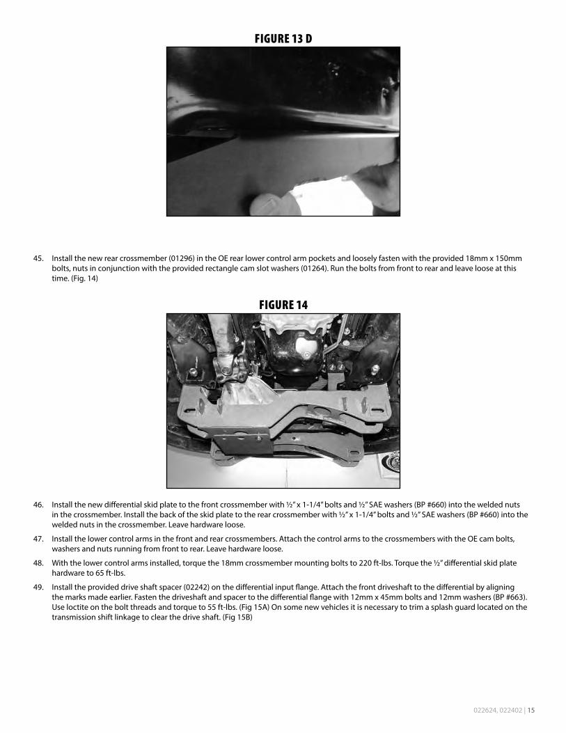
45. Install the new rear crossmember (01296) in the OE rear lower control arm pockets and loosely fasten with the provided 18mm x 150mm bolts, nuts in conjunction with the provided rectangle cam slot washers (01264). Run the bolts from front to rear and leave loose at this time. (Fig. 14)
FIGURE 14
46. Install the new differential skid plate to the front crossmember with ½” x 1-1/4” bolts and ½” SAE washers (BP #660) into the welded nuts in the crossmember. Install the back of the skid plate to the rear crossmember with ½” x 1-1/4” bolts and ½” SAE washers (BP #660) into the welded nuts in the crossmember. Leave hardware loose.
47. Install the lower control arms in the front and rear crossmembers. Attach the control arms to the crossmembers with the OE cam bolts, washers and nuts running from front to rear. Leave hardware loose.
48. With the lower control arms installed, torque the 18mm crossmember mounting bolts to 220 ft-lbs. Torque the ½” differential skid plate hardware to 65 ft-lbs.
49. Install the provided drive shaft spacer (02242) on the differential input flange. Attach the front driveshaft to the differential by aligning the marks made earlier. Fasten the driveshaft and spacer to the differential flange with 12mm x 45mm bolts and 12mm washers (BP #663). Use loctite on the bolt threads and torque to 55 ft-lbs. (Fig 15A) On some new vehicles it is necessary to trim a splash guard located on the transmission shift linkage to clear the drive shaft. (Fig 15B)

16 | 022624, 022402
FIGURE 15A FIGURE 15B
50. Steps 51-54. In order to give a close to level stance after installation, preload spacers are included in these systems. Install the preload
spacers if a more level stance is desired. The preload spacer will reduce the rake by an additional 5/8”. Place indexing marks on the strut body, strut cap and upper coil seat (Fig 16A, 16B) for realignment of the components when the strut is reassembled.
FIGURE 16A
FIGURE 16B
Coil spring is under extreme pressure. Improper removal/installation of coil spring could result in serious injury or death. Use only a high-quality spring compressor and carefully read and follow the manufacturer’s instructions.
51. Using an appropriate strut compressor, compress the coil spring and remove the upper strut nut (Fig 17). Remove the strut, strut cap and upper coil seat from the coil spring.

022624, 022402 | 17
FIGURE 17
52. Place the provided preload spacer (01278) between the plastic coil seat and the rubber isolator (Fig 18).
FIGURE 18
53. Reassemble the strut as it was taken apart by aligning the index marks made earlier. Fasten the assembly with the OE strut nut. Torque nut to 50 ft-lbs.
54. 4 inch kit only: Rotate the top of the strut 180 degrees. This will change the position of the coil bow to give enough clearance to the frame rail. Compress the coil slightly to allow the top plate, and only the top plate to rotate around 1/2 turn. This must be done for both strut assemblies.
55. Install the provided strut spacers (01267 - 6in kit or 02267 - 4in kit) on the struts with the original strut mounting hardware. Torque nuts to 30 ft-lbs.
56. Loosely install the strut assemblies on the appropriate sides of the truck with the provided 10mm nuts and washers (BP #662) on the strut spacer studs.
57. Install the new driver’s side steering knuckle to the driver’s side lower control arm ball joint and loosely attach with the original nut. Install the driver’s side CV axle in the hub and loosely fasten with the original axle nut. Swing the knuckle/CV assembly up while aligning the axle with the differential output shaft. Loosely attach the strut to the lower control arm with the original hardware. Push the CV axle all the way onto the differential output to seat the internal retaining clip.
58. Support the lower control arm with a hydraulic jack and attach the knuckle to the upper ball joint with the OE nut.
59. Torque the upper ball joint nut to 55 ft-lbs and the lower ball joint nut to 60 ft-lbs. Torque the axle nut to 185 ft-lbs. Torque the upper strut-to-frame nuts to 30 ft-lbs.
60. Repeat knuckle/CV installation on passenger’s side.
61. Install the brake rotor and caliper on the knuckle/hub. Torque the OE caliper bolts to 130 ft-lbs. Use loctite on the caliper bolts.
62. Trim 5/8” from the male thread on the inner tie rod. Take care not to trim too much off from the male threads to ensure adequate tie rod thread engagement.
63. Locate the provided tie rod ends and OE jam nuts and install them on the inner tie rod. Attach the tie rod ends to the new steering knuckles with the included nut. Torque to 55 ft-lbs. Securely lock off the jam nut. It is recommended to have approximately 2 threads left exposed past the jam nut for ease of alignment adjustment.

18 | 022624, 022402
64. Reconnect the ABS wires at the frame.
65. Route the brake and ABS lines around the back side of the knuckle. Attach the brake line and ABS wire with 1/4” hardware and clamps bolt pack #823 / 662 to the threaded hole in the backside of the steering knuckle. There is an included large diameter clamp that is not used with this kit. Secure the ABS wire with zip ties at other locations to prevent any contact with rotating / moving parts. Ensure there is adequate slack and clearance between the brake line and suspension components. (Fig 19a)
66. Install the sway bar link extension onto the factory sway bar link. Attach the assembly to the sway bar with the factory bushing, new cup washers, and 7/16” nylock nuts (#662)) and Loc-tite on threads to attach to the factory sway bar link.. Tighten bolt until bushings begin to
deform. It is NOT necessary to over tighten the bolt. Over tightening will cause premature bushing wear. (Fig 19b)
FIGURE 19A
FIGURE 19A
67. Remove the stock CV boot clamp on the front driveshaft at the transfer case. Slide the boot rearward approximately 1/4” and install the new boot clamp, rotate the driveshaft to ensure that the clamp does not interfere with the lip on the front driveshaft. (Fig 20a, 20b)
FIGURE 20A FIGURE 20B

022624, 022402 | 19
68. Reinstall front wheels. Torque to OE specifications, see owner’s manual.
69. Lower the vehicle to the ground and bounce the front to settle the suspension.
70. Center the lower cams and torque lower control arm hardware to 125 ft-lbs. Torque the strut-to-lower control arm bolt to 125 ft-lbs.
71. If the front brakelines were disconnected or replaced, the front brakes must be bled before driving vehicle. Also do a final check to ensure the brake lines will not contact the tire or other moving components.
72. Check all fasteners for proper torque. Recheck all fasteners after 500 miles and at regularly scheduled maintenance intervals.
73. A complete front end alignment is required. Do not drive the vehicle with the steering wheel off center. This can cause unsafe driving conditions.
Thank you for choosing BDS Suspension.For questions, technical support and warranty issues relating to this BDS Suspension product, please contact your distributor/installer
before contacting BDS Suspension directly.