4 4 6 . 3 2 6 A C A D / C A M
40
1 4 4 6 . 3 2 6 A C A D / C A M Design for X (DFX) December 5, 2007 Sung-Hoon Ahn School of Mechanical and Aerospace Engineering Seoul National University Introduction of DFX Success in product manufacturing requires integration between the various phases of the product life cycle. – Ulrich and Eppinger, 1995 One of the key aspects of integration during the design process is “Design for X (DFX)” - Design for Manufacturing (DFM) - Design for Assembly (DFA) - Design for Disassembly (DFDA) - Design for Environment (DFE)
Transcript of 4 4 6 . 3 2 6 A C A D / C A M

1
4 4 6 . 3 2 6 A C A D / C A M
Design for X (DFX)
December 5, 2007
Sung-Hoon AhnSchool of Mechanical and Aerospace Engineering
Seoul National University
Introduction of DFX
Success in product manufacturing requires integration between the various phases of the product life cycle.
– Ulrich and Eppinger, 1995
One of the key aspects of integration during the design process is “Design for X (DFX)”- Design for Manufacturing (DFM)- Design for Assembly (DFA)- Design for Disassembly (DFDA)- Design for Environment (DFE)

2
1. Design for Manufacturing (DFM)
Traditional Design and Manufacturing Process
Design
Knowledge
Over the WallManufacturing
Manufacturing
Time lost in trial and error
Isolated
1. Design for Manufacturing (cont.)
Paradigms of DFM- Design decision affects
manufacturing cost and productivity
- Designers play important role not only in shaping, but also in manufacturability, cost, and life cycle of products

3
1. Design for Manufacturing (cont.)
Objectives of DFM- Identify product concepts which are inherently easy to manufacture- Design components for ease of manufacture.- Integrate product and process design to ensure an optimum
combination of function and manufacturability.
Cost ofChanges
Time
OptimalPlanning
TraditionalPlanning
< Costs of change vs. time >
DesignCompletness
100%
Time
Traditional
DFM
< Design completeness vs. time >
History of DFM I
Eli Whitney (19C )- Musket (gun) manufacturer- Redesign each part to a specific
dimension with a limited tolerance- Using fixtures, gauges, and specially
developed machines, each part could be made by semi-skilled workers (instead of expert artisans) at a faster and less costly rate
- Changed manufacturing process of parts from sand casting to forging resulted in increased accuracy

4
History of DFM I (cont.)
Whitney’s Musket
History of DFM II
Henry Ford (1907)- Lower cost from
standard parts- Simple part design- Mass production
Conveyor system- Price reduction- $2000/car $350/car- 1908~1927: 15 million cars sold
5
DFM category
GeneralProcess specificProduct specificDesign for Assembly (DFA)
General principles of DFM
Minimum number of partsStandard partsModular designMulti-functional partsThe same parts to various productsMaximum surface roughness and toleranceAvoid secondary processUse materials easy to manufactureConsider number of parts to be manufacturedAvoid many componentsMinimize handling of parts

6
General principles of DFM (cont.)
Per part costManufacturing Time vs. Surface Roughness
Fabrication of Microchip - l
Microchip for capillary electrophoresis- Typical micro component of μ-TAS (Micro Total Analysis System)- Dimensions of micro chip
• Channel width: 200 ㎛• Channel height: 300 ㎛• Reservoir diameter: 1 mm• Reservoir 2 – 4 : 45 mm• Reservoir 1 – 3 : 10 mm
Fabrication via direct machining- Machining with φ200 ㎛ endmill on PMMA- Machining conditions
• Feed rate: 0.1 mm/s• Spindle speed: 30,000 rpm• Depth of cut: 30 ㎛• Machining time: 51 min
- Prototype within 2㎛ dimensional error
40mm
5mm
The 2-D Drawing of Microchip
Reservoir 1 -4Reservoir 1: buffer reservoirReservoir 2: Sample injectionReservoir 3: Sample wasteReservoir 4: Separation channel
Microchip by direct machining
7
(a) PR patterning on silicon
(b) Silicon DRIE for channel
(c) Oxide deposition on backside
(d) Ti / Au sputtering
(d) Ni electroplating
(e) Ti/Au/Silicon removal (TMAH / HF)
(a) PR patterning on silicon
(b) Silicon DRIE for channel
(c) Hot embossing with PMMA
(d) PMMA plate fusion bonding
(d) Detaching the silicon mold
Hot Embossing / Si mold Hot Embossing / Ni mold Injection Molding
(a) CAD modeling
(b) Tool path generate
(c) Machining
(d) Injection molding
30 min$6.65
1 min$102.66
30 min$14.26
1 hr$28.52
8 – 10 hr$165.4
30 min$30
15 min
15 min
1 hr
15 min
1h$6.65
1 hr$102.66
5 min$42.78
30 min$6.65
30 min
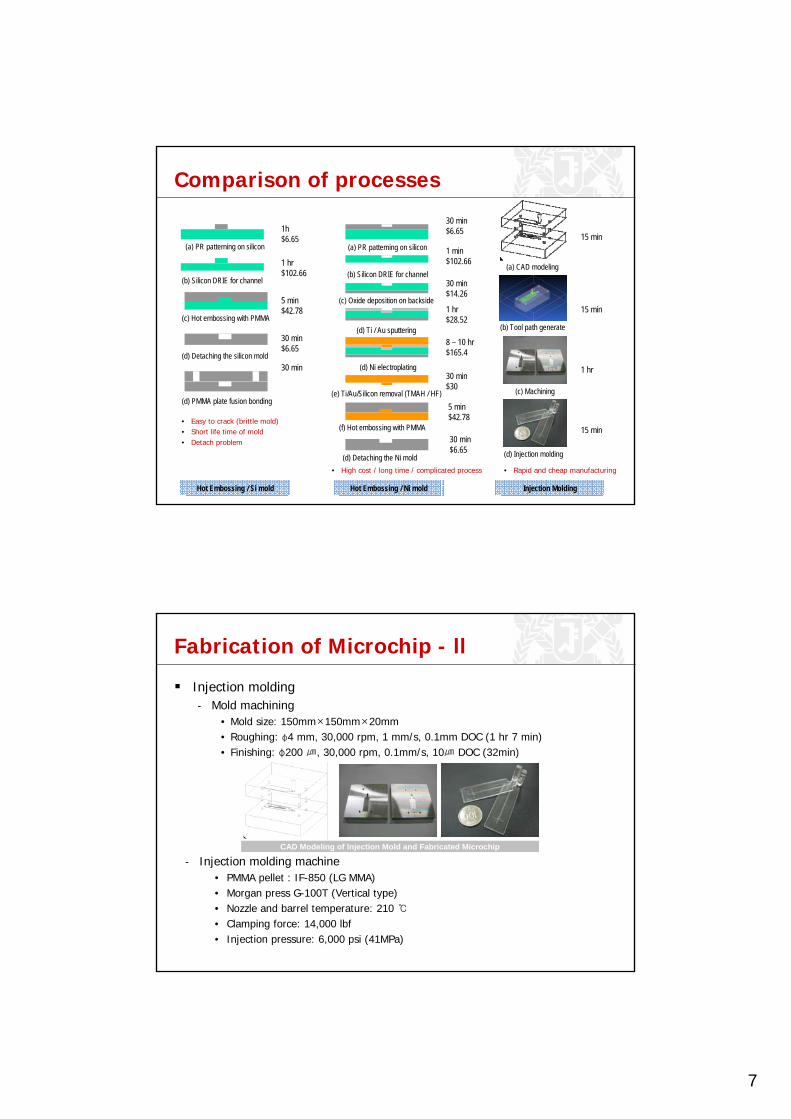
• Easy to crack (brittle mold)• Short life time of mold• Detach problem
• High cost / long time / complicated process • Rapid and cheap manufacturing
(f) Hot embossing with PMMA
(d) Detaching the Ni mold
5 min$42.78
30 min$6.65
Comparison of processes
Fabrication of Microchip - ll
- Injection molding machine• PMMA pellet : IF-850 (LG MMA)• Morgan press G-100T (Vertical type)• Nozzle and barrel temperature: 210 ℃• Clamping force: 14,000 lbf• Injection pressure: 6,000 psi (41MPa)
CAD Modeling of Injection Mold and Fabricated Microchip
Injection molding- Mold machining
• Mold size: 150mm×150mm×20mm• Roughing: φ4 mm, 30,000 rpm, 1 mm/s, 0.1mm DOC (1 hr 7 min)• Finishing: φ200 ㎛, 30,000 rpm, 0.1mm/s, 10㎛ DOC (32min)
8
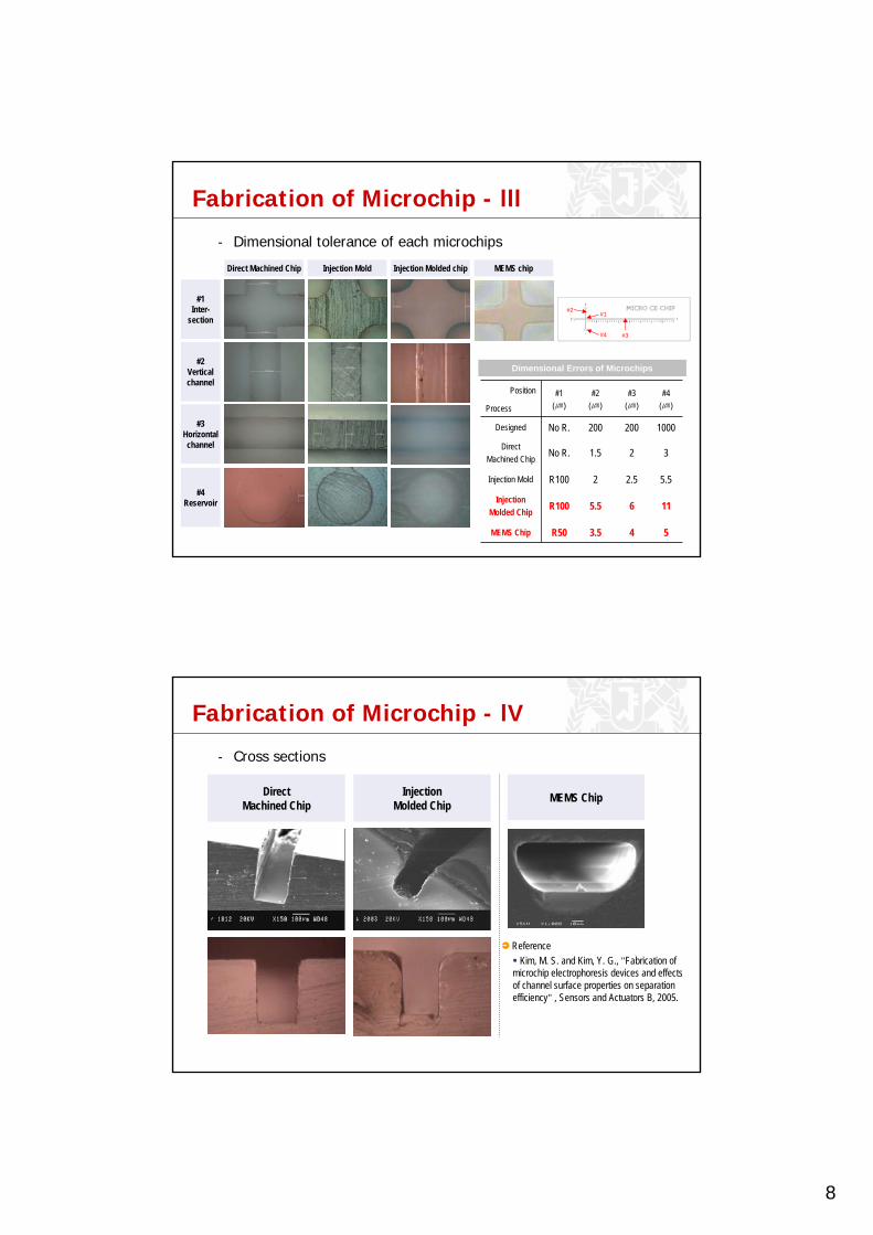
Fabrication of Microchip - lll
543.5R50MEMS Chip
6
2.5
2
200
#3(㎛)
115.5R100Injection Molded Chip
5.52R100Injection Mold
31.5No R.Direct Machined Chip
1000200No R.Designed
Process#4
(㎛)#2
(㎛)#1
(㎛)Position
#1Inter-
section
#2Verticalchannel
#3Horizontalchannel
Direct Machined Chip Injection Molded chipInjection Mold
#4Reservoir
Dimensional Errors of Microchips
#1#2
#3#4
MEMS chip
- Dimensional tolerance of each microchips
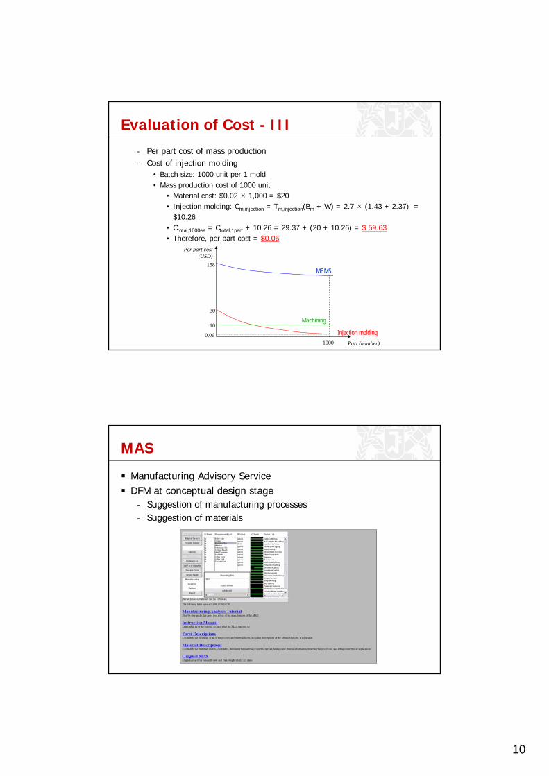
Fabrication of Microchip - lV
DirectMachined Chip
InjectionMolded Chip MEMS Chip
ReferenceKim, M. S. and Kim, Y. G., "Fabrication of
microchip electrophoresis devices and effects of channel surface properties on separation efficiency" , Sensors and Actuators B, 2005.
- Cross sections

9
Evaluation of Cost
Cost Estimation- Total cost of mechanical micro machining: Ctotal = Cw + Cp + Cm + Ct
[ ]⎟⎠⎞
⎜⎝⎛+=
100%_ overheadmachineMMB ttm
⎟⎟⎠
⎞⎜⎜⎝
⎛×
=periodrepaymenthoursworking
tmachinepurchaseinitialMt __cos___
n
VCT
1
⎟⎠⎞
⎜⎝⎛=
Material Cost Preparation Cost Machining Cost Tool Cost
Total Cost of Mechanical Micro Machining
V: volumeρ: densityCum: mass per unit
W: wage per hourTp: preparation time
(hour)
W: wage per hourTm: machining time (hour)Bm : Indirect costMt: Depreciation rate
y: initial tool costTm: machining time (hour)T: tool lifeV: cutting speed
Cw Cp Cm Ct
umw CVC ρ= pp WTC = ( )mmm BWTC += ⎟⎟⎠
⎞⎜⎜⎝
⎛=
TT
yC mt
Evaluation of Cost - II
Cost Evaluation- Bm (Indirect cost)
- Mt (Depreciation rate)
- Tool life of macro scale
- Reference of rental fee (MEMS)• Inter-university Semiconductor
Research Center (SNU)
$158.23/ea$29.37/ea$11.04/eaTotal
$4.65$4Subtotal
545minTfinishing
141minTroughing9hr: at 0.1mm/sT
-nfinishing
0.14nroughing0.14n
-Vfinishing
300m/minVroughing300m/minV
-Cfinishing
600Croughing600C
32 minTm,finishing
67 minTm,roughing51 minTm
$43/eayfinishng
$4/eayroughing$43 /eay
Ct
$15.36 $6.62 Subtotal
$2.37/hrW$2.37 /hrW
$1.43 Bm,injection
$5.42 Bm,machining$5.42 Bm
$0.48 Mt,injection
$1.81 Mt,machining$1.81 Mt
1 minTm,injection
32 minTm,finishing
67 minTm,roughing.
51 minTm
Cm
$1.58 $0.4 Subtotal
$2.37/hrW$2.37 /hrW
30 minTp,injection.
10 minTp,machining.10 minTpCp
Wafer$28.52
PRpatterning
$6.65
Mask$266
DRIE$96.05
Oxidation$14.26
Ti/Au sputtering
$28.52
Ni electro-plating$165.4
Si/Au/Ti removal$28.53
Total$632.92
/4ea
$7.78 Al$0.02 PMMACw
MEMSInjection molding Direct machiningItem
[ ]⎟⎠⎞
⎜⎝⎛+=
100%_ overheadmachineMMB ttm
⎟⎟⎠
⎞⎜⎜⎝
⎛×
=periodrepaymenthoursworking
machineoftpurchaseinitialMt ____cos__
n
VCT
1
⎟⎠⎞
⎜⎝⎛= C, n: empirical constant
V: cutting speed
10
Evaluation of Cost - III
- Per part cost of mass production- Cost of injection molding
• Batch size: 1000 unit per 1 mold• Mass production cost of 1000 unit
• Material cost: $0.02 × 1,000 = $20• Injection molding: Cm,injection = Tm,injection(Bm + W) = 2.7 × (1.43 + 2.37) =
$10.26• Ctotal,1000ea = Ctotal,1part + 10.26 = 29.37 + (20 + 10.26) = $ 59.63• Therefore, per part cost = $0.06
0.06
10
158
30
1000 Part (number)
Per part cost(USD)
MEMS
Machining
Injection molding
MAS
Manufacturing Advisory ServiceDFM at conceptual design stage
- Suggestion of manufacturing processes- Suggestion of materials
11
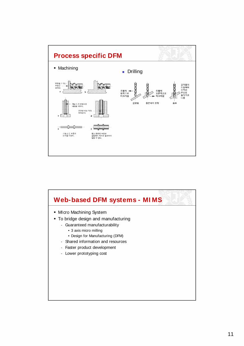
Process specific DFM
MachiningDrilling
Web-based DFM systems - MIMS
MIcro Machining SystemTo bridge design and manufacturing
- Guaranteed manufacturability• 3 axis micro milling• Design for Manufacturing (DFM)
- Shared information and resources- Faster product development- Lower prototyping cost

12
Web-based DFM systems - MIMS
Architecture- Web-based system
Web-based DFM systems - MIMS
DFM in machining: User Level- Expert mode:
• 16 parameters• Max. control
- Novice mode:• 2 parameters
• Roughing• Tool diameter
• Easy interface

13
Web-based DFM systems - MIMS
DFM: Thin Client UI- HTML form- Tool database- Interpolation tolerance 1㎛
Web-based DFM systems - MIMS
DFM: NC Code Simulation
Issues in micro regimeRun-outTolerance of software
14
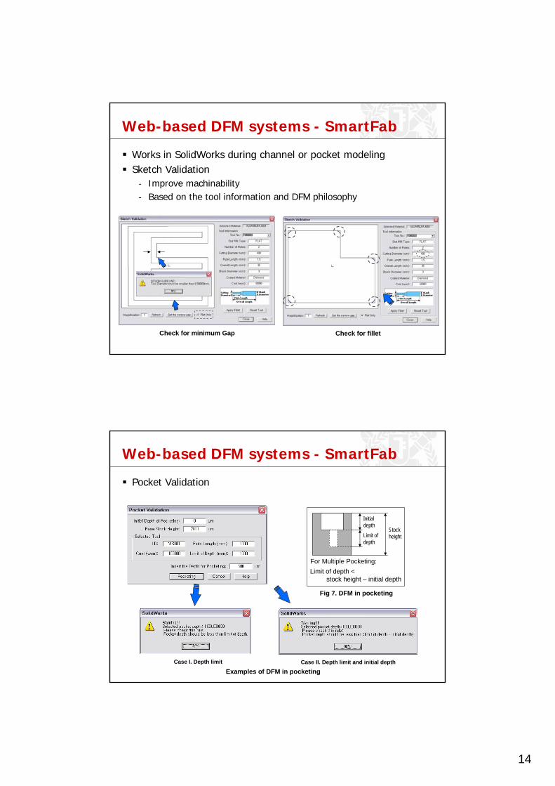
Web-based DFM systems - SmartFab
Check for minimum Gap Check for fillet
Works in SolidWorks during channel or pocket modelingSketch Validation
- Improve machinability- Based on the tool information and DFM philosophy
Web-based DFM systems - SmartFab
Case I. Depth limit Case II. Depth limit and initial depth
Initialdepth
StockheightLimit of
depth
Limit of depth < stock height – initial depth
For Multiple Pocketing:
Fig 7. DFM in pocketing
Examples of DFM in pocketing
Pocket Validation
15
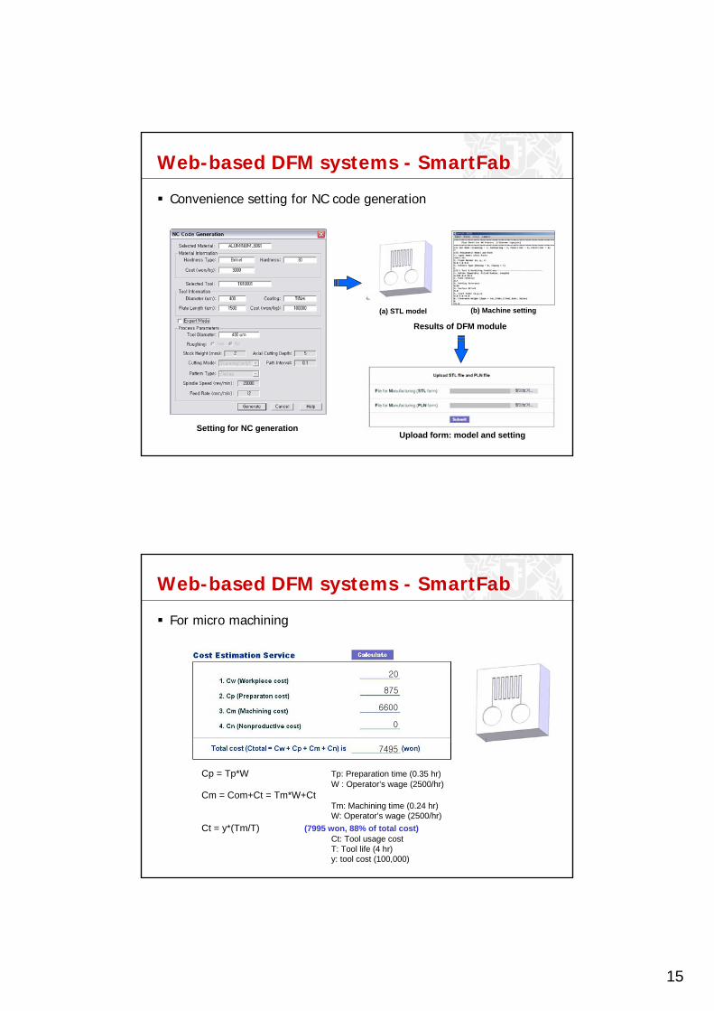
Web-based DFM systems - SmartFab
(a) STL model (b) Machine setting
Setting for NC generation
Results of DFM module
Upload form: model and setting
Convenience setting for NC code generation
Web-based DFM systems - SmartFab
Cp = Tp*W Tp: Preparation time (0.35 hr)W : Operator’s wage (2500/hr)
Cm = Com+Ct = Tm*W+CtTm: Machining time (0.24 hr)W: Operator’s wage (2500/hr)
Ct = y*(Tm/T) (7995 won, 88% of total cost)Ct: Tool usage cost T: Tool life (4 hr)y: tool cost (100,000)
20
875
6600
0
7495
For micro machining
16
DFM for RP
Issues in FDM material (ABS)Porous & directionalBuild rule…
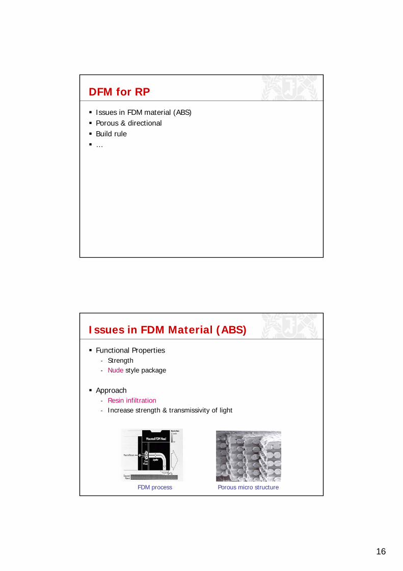
Issues in FDM Material (ABS)
Porous micro structureFDM process
Functional Properties- Strength- Nude style package
Approach- Resin infiltration- Increase strength & transmissivity of light
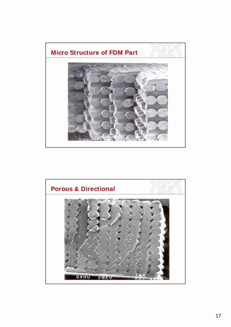
17
Micro Structure of FDM Part
Porous & Directional

18
Anisotropy in FDM Parts
Quickslice SML file.SEM picture of FDM specimen.
“Raster Orientation” is the direction of deposition
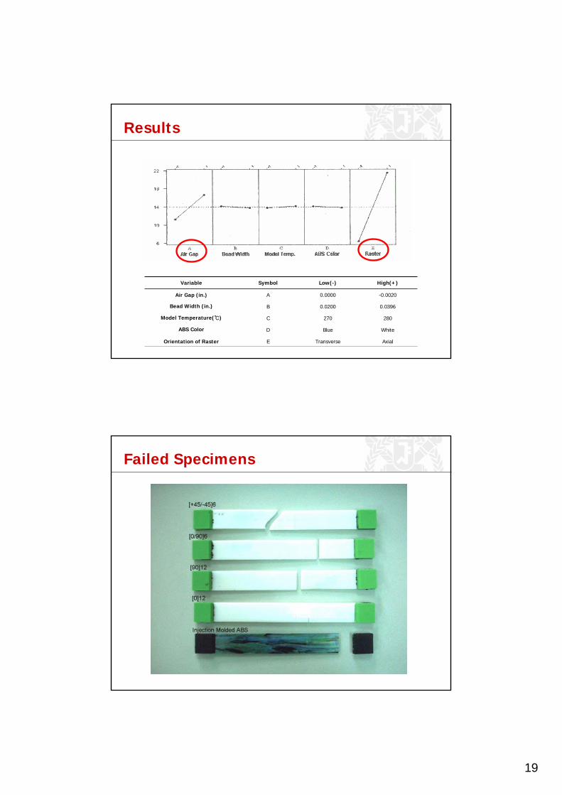
Design of Experiment (DOE)
19
Results
AxialTransverseEOrientation of Raster
WhiteBlueDABS Color
280270CModel Temperature(℃)
0.03960.0200BBead Width (in.)
-0.00200.0000AAir Gap (in.)
High(+)Low(-)SymbolVariable
Failed Specimens

20
Build Rule #1
Build parts such that tensile loads will be carried axially along the fibers.
Cross Section 1 Cross Section 2Two different road orientations for boss design.
Build Rule #1 cont’d
Cross Section 1 Cross Section 2
Two different road orientations for cantilever snap-fit design.
21
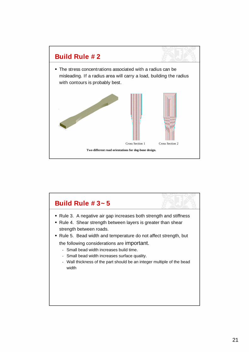
Build Rule #2
The stress concentrations associated with a radius can be misleading. If a radius area will carry a load, building the radius with contours is probably best.
Cross Section 1 Cross Section 2
Two different road orientations for dog-bone design.
Build Rule #3~5
Rule 3. A negative air gap increases both strength and stiffnessRule 4. Shear strength between layers is greater than shear strength between roads.Rule 5. Bead width and temperature do not affect strength, but the following considerations are important.
- Small bead width increases build time.- Small bead width increases surface quality.- Wall thickness of the part should be an integer multiple of the bead
width

22
Raw FDM ABSi After InfiltrationDuring Infiltration
0
0.1
0.2
0.3
0.4
0.5
0.6
800 760 720 680 640 600 560 520 480 440 400
Wave length(nm)
Tra
nsm
issiv
ity(
%)
0
5
10
15
20
25
-0.003 0 0.003
Air Gap(inch)
Tra
nsm
issi
vity
(%)
Raw material Infiltration Infiltration+Sanding
Resin Infiltration
1.511.691.57Index of Refraction
Cyano AcrylateAcrylABSi
Relative Transmissivity

23
DFM in Injection Molding
DFM in Injection Molding (cont.)
Prevent undercut

24
DFM in Injection Molding (cont.)
Warpage and sinkmarks
Avoid thick “hot spots”

25
Injection and flow
Max length of flow- Part Thickness- Material
Influences decision on- Part Geometry- Number of gates- Location of gates
• Weldline
Avoid undercut
Undercut requires cam pin, slider, or lifter

26
Key issues for each sub-process
Injection- Flow Length Limit, Weldlines, and Density Dist.- Gating Scheme (number and location)- Thickness
Packing and Cooling- Differential Cooling, Warpage, and Sinkmarks- Geometry Design
Ejection (Tooling)- Parting Plane (Undercut)- Ejector Pins
Assembly- Integral hinges and fasteners, Welding
Product specific DFM
Example: GM 3.8 liter V6 engine
Airintake manifoldsOriginal : Cast AlRedesigned : molded
thermoplastic composite

27
Design for Assembly (DFA)
Benefit of DFA- Fewer Parts- Easier Assembly- Shorter Assembly Time- Major Concurrent Engineering Driver
• Major Cost Savings (Parts and Labor)• Reduced Defects• Improved Quality• Increased Reliability
Design for Assembly (cont.)

28
Design for Assembly (cont.)
Design for Assembly (cont.)
Minimum number Multi-functional Part- Compliant (flexible) part

29
Design for Assembly (cont.)
Self Location
Design for Assembly (cont.)
Example: Lego
30
Design for Assembly (cont.)
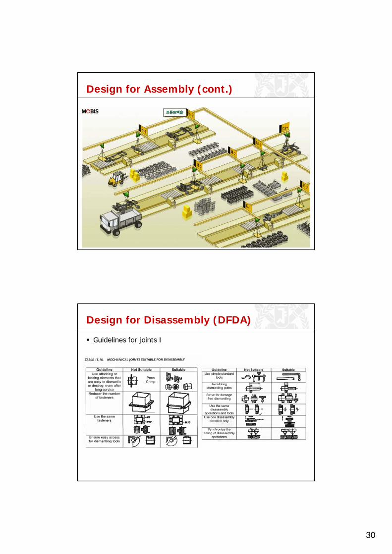
Design for Disassembly (DFDA)
Guidelines for joints I
31
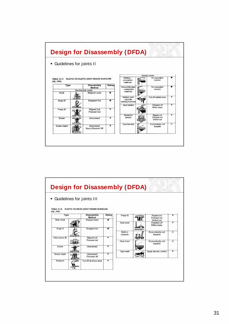
Design for Disassembly (DFDA)
Guidelines for joints II
Design for Disassembly (DFDA)
Guidelines for joints III

32
Design for Disassembly (DFDA)
Time issue- Logitech MX300
Mouse
Assy1
Assy2
Screw* 1
Assy1-1
PCB1
Screw* 2
WheelAssy
Assy2-1
Button1
Button2
Assy1-1-1
Assy1-1-1-1
UpperCover
Screw* 1
LowerCover
SteelBlock
Screw* 1
WheelBase Wheel Steel Wire
* 2 Base PCB2
Screw* 2
Cable1
Screw * 2 = 8 sec Insert * 2 = 2 sec
Screw * 1 = 4 sec
Snap fit * 2 + Insert * 1 = 5 sec Screw * 2 + Insert * 1= 8 sec Screw * 2 = 8 sec
Screw * 1 + Snap fit * 4 = 20 sec
Screw * 1 = 4 secTotal Disassembly time:59 sec
Assembly Single partInsert: x sec Snap fit: x^2 sec Screw: 4x sec x: # of items
Design for Disassembly (DFDA)
Time issue- Microsoft Explorer
Assembly Single partInsert: x sec Snap fit: x^2 sec Screw: 4x sec x: # of items
Mouse
Assy1
Assy2
Screw* 1
Assy1-1
SideButton 1
SideButton 2 Wheel PCB
Set(3)
Button Screw*2
Opticalpart
Screw * 2 + Snap fit * 2 + 5(for Rubber pad) = 17 sec
Snap fit * 2 * 2 = 8 sec
Screw * 2 + Snap fit * 3 = 17 sec
RubberPad * 2
Screw*2
Screw * 2 + Snap fit * 2 * 2 + 10(for PCB Set) = 26 sec
Total Disassembly time:68 sec

33
Design for Environment (DFE)
Benefit of DFE- Reduced health, safety, and ecological risks- Increased efficiency and customer acceptance- Improved worker morale and productivity- Reduced regulatory burden- Improved channels of communication, cooperation, and
collaboration among stakeholder organizations- Expanded business and market opportunities
- DFE includes• Design for Recycling• Design for remanufacturing• Design for energy efficiency
- from U.S. Envrionmental Protection Agency (EPA),http://www.epa.gov/oppt/dfe
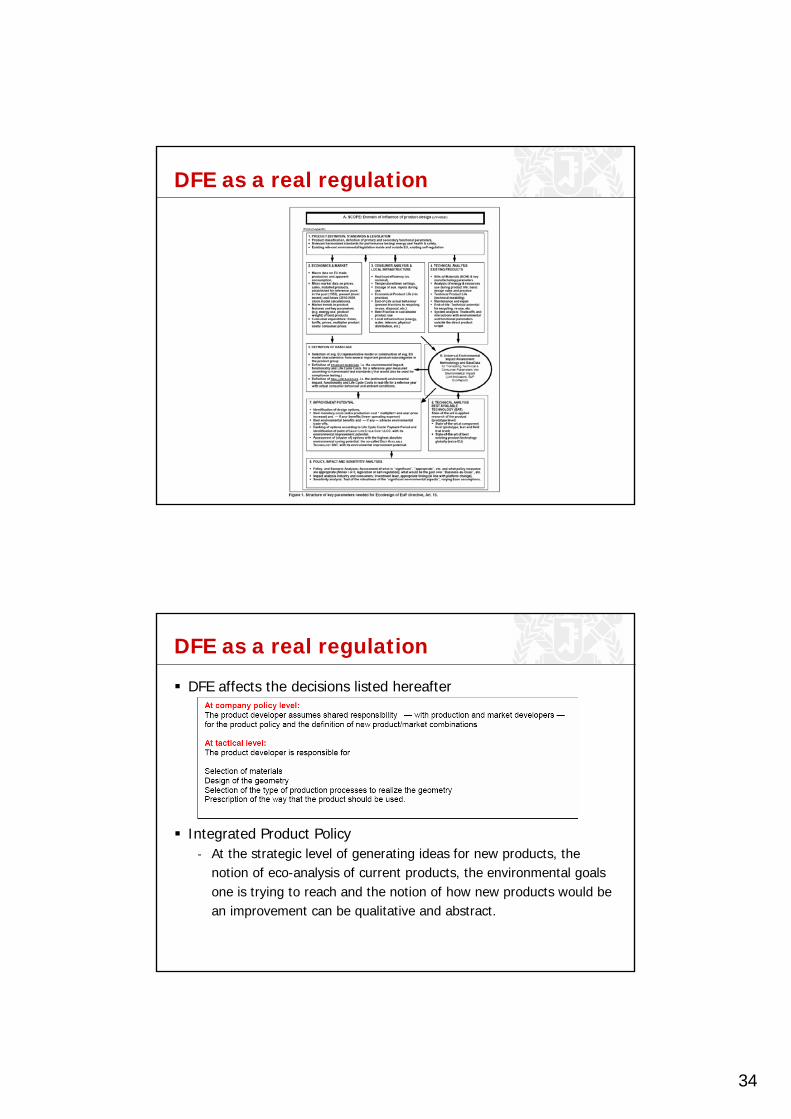
DFE as a real regulation
Eco Design(DFE) of EuP Directive 2005/32/EC- EuP : Energy using Products which use any forms of energy- All EU countries must legislate for this EuP Directive until 11th
August, 2007.
< A Part of Direcrive 2005/32/EC Article 15 >
34
DFE as a real regulation
DFE as a real regulation
DFE affects the decisions listed hereafter
Integrated Product Policy- At the strategic level of generating ideas for new products, the
notion of eco-analysis of current products, the environmental goals one is trying to reach and the notion of how new products would be an improvement can be qualitative and abstract.

35
DFE as a real regulation
Integrated Product Policy- At such level, a company may decide for instance that all-in-one
imaging center is more environmentally friendly than a single product. The DFE dimension, as one of the many factors that are taken into consideration, can be an inspiration and guidance.
Design for recycling

36
Design for recycling (cont.)
Design for recycling (cont.)
37
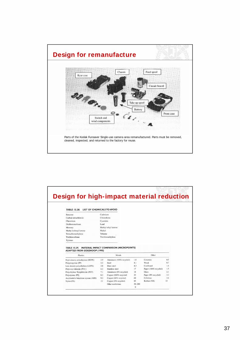
Design for remanufacture
Parts of the Kodak Funsaver Single-use camera area remanufactured. Parts must be removed, cleaned, inspected, and returned to the factory for reuse.
Design for high-impact material reduction

38
Design for energy efficiency
Design for class project
Minimum part sizeMinimum thicknessMaximum part sizeManufacturing cost Machining
- No undercut for 3 axis milling and turning- Fixturing-vise, vacuum chuck
RP- Surface roughness and post process- Strength
Injection molding- Draft angle- No undercut, or undercut with slider mechanism
39
Case study #1
Mold making- CNC, milling, turning- sanding- Channels for air escape
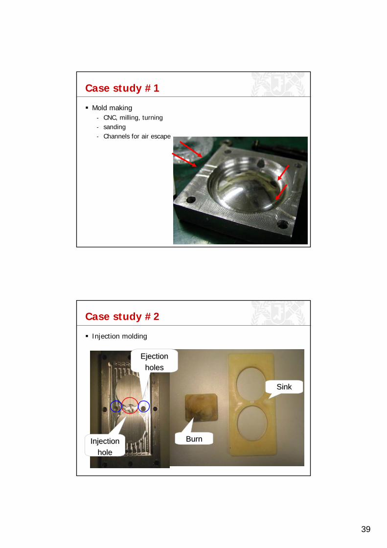
Case study #2
Injection molding
● Temperature● Pressure● Taper & Ejection holes● Expansion rate of『ABS』
● Burn● Sink
InjectionInjectionholehole
EjectionEjectionholesholes
BurnBurn
SinkSink

40
Case study #3
Re-design for injection molding
BeforeBefore
AfterAfter
DeleteDelete
ModifyModify