4-1600 API Ipieca Workshop Ritter Lng Final Mar2012 Speaker
16
CONSISTENT METHODOLOGY FOR ESTIMATING GREENHOUSE GAS EMISSIONS FROM LNG OPERATIONS Karin Ritter, API
Transcript of 4-1600 API Ipieca Workshop Ritter Lng Final Mar2012 Speaker

CONSISTENT METHODOLOGY FOR
ESTIMATING GREENHOUSE GAS EMISSIONS
FROM LNG OPERATIONS
Karin Ritter, API
API LNG Guideline Document
Goals
– Develop consistent internationally accepted methodologies to estimate GHG emissions from operations in the Liquefied Natural Gas (LNG) value chain
Background
– Initiated as part of API’s contribution to the Cleaner Fossil Energy Task Force of the Asia Pacific Partnership
– Designed to align with other industry guidance, i.e. API Compendium, IPIECA Guidelines
3
LNG Document Overview
The LNG document consists of,
– Description of LNG operations chain
– Methods and emission factors unique to this
industry segment
Emission estimation methods build on the API
Compendium with an expansion to LNG
specific sources and operations
Data reporting consistent with the IPIECA /API
Petroleum Industry Greenhouse Gas
Reporting Guidelines
Document to be publicly available

Document Development Process
Established a U.S. based working group of
companies technical experts
– Collaborating with CLNG
Defined LNG segment boundaries and identified
applicable emission sources
Adopted available emissions estimation
methodology for LNG operations
– Build on methods available in API Compendium
Conducted several rounds of review and comment
by a broader cadre of industry experts
– Special review meeting with APPEA in Australia

Document Contents
LNG OVERVIEW
LNG SECTOR BACKGROUND
GHG INVENTORY BOUNDARIES & SCOPE
EMISSION ESTIMATION METHODS
– Stationary Combustion Emissions Estimation
– Vented Emissions
– Fugitive Emissions
– Transportation Emissions
– Non-routine emissions
Appendices • A – Glossary of terms
• B – Unit conversions
• C – Acronyms

Section 1: LNG Overview
Broad overview of the LNG sector
– EIA LNG outlook to 2030
– LNG capacity under construction outside
of North America
– Contribution of LNG to national emission
inventories
Note
• The section does not intend to
provide an in-depth LNG outlook

Section 2: LNG Sector Background
Definition of LNG
Listing of selected
LNG compositions
and HHVs for select
countries of origin
LNG applications
LNG operations
chain
Description of LNG
Operations Courtesy: MEI, LLC

Description of LNG Operations
LNG Operations boundaries
– Starts at the entry of gas to the liquefaction plant
– Terminates after regassification of liquids and
transfer for transport and marketing
Segments of the LNG Operations Chain
– Liquefaction
– Storage
– Loading and Unloading
– Shipping
– Regassification

Key Contributors to GHG Emissions
Emissions depend on facility design and operating practices – Types of storage tanks used
– Level of compression used
– Vessel pre-cooling practices
– Boil-off gas recovery
Types of vaporizers used are key contributors to regassification emissions – Submerged Combustion Vaporizers (SCV)
– Open Rack Vaporizers (ORV)
– Shell & Tube Vaporizers (STV)
– Ambient Air Vaporizers (AAV)

Above Ground Storage Tanks
Source: Kotzot et al, 2003

Section 3: GHG Inventory Boundaries
This section links the ultimate reporting of GHG
emissions from LNG operations to the
IPIECA/API Industry GHG Reporting Guidelines
GHG emission sources
– Provides detailed mapping of Combustion Sources
– Provides detailed mapping of Vented, Fugitives and
Mobile Emission Sources
GHG compounds emitted
– Emissions and quantification methods focus on CO2,
CH4, and N2O

Section 4:
GHG Emission Estimation Methods
Focus on five categories of sources
– Stationary combustion emissions;
– Process vents and other vented emissions;
– Fugitive emissions from equipment leaks;
– Mobile source combustion emissions.
– Non-routine emissions
Methods that are included in the API Compendium
are not repeated here
Tables provide listing of applicable emission
factors
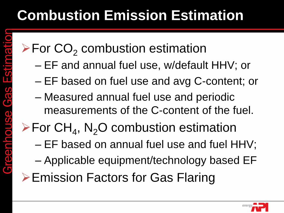
Combustion Emission Estimation
For CO2 combustion estimation
– EF and annual fuel use, w/default HHV; or
– EF based on fuel use and avg C-content; or
– Measured annual fuel use and periodic
measurements of the C-content of the fuel.
For CH4, N2O combustion estimation
– EF based on annual fuel use and fuel HHV;
– Applicable equipment/technology based EF
Emission Factors for Gas Flaring
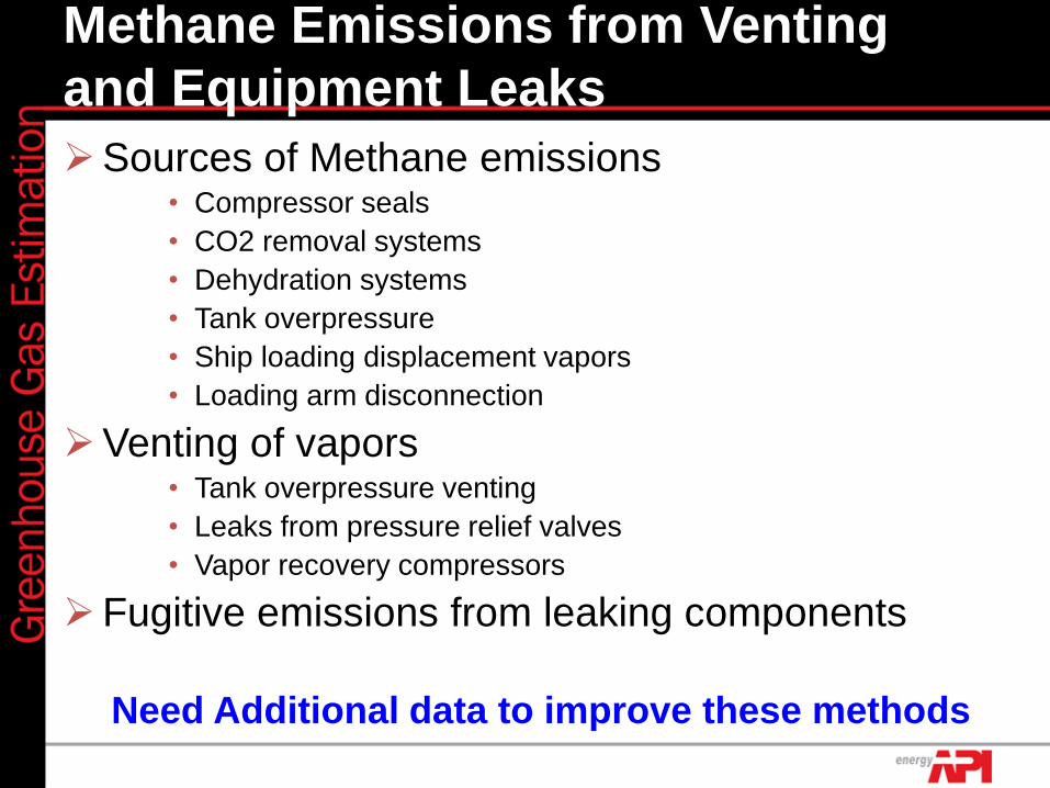
Methane Emissions from Venting
and Equipment Leaks
Sources of Methane emissions • Compressor seals
• CO2 removal systems
• Dehydration systems
• Tank overpressure
• Ship loading displacement vapors
• Loading arm disconnection
Venting of vapors • Tank overpressure venting
• Leaks from pressure relief valves
• Vapor recovery compressors
Fugitive emissions from leaking components
Need Additional data to improve these methods

Next Steps
Completed final round of industry
experts review and comments
In process of incorporating and
updating document based on
comments
Publish ‘Pilot Version’ document for
field testing of document globally
Undertake follow-up review and
revision with new information being
made available during ‘pilot period’
Thank you for your attention
Karin Ritter, API, Washington DC, USA
Dr. Miriam Lev-On, LEVON Group, California, USA
Thank you for your attention
For additional information: