4 + 1 QUIK-CHANGE TRANSMISSION -...
9
"4 + 1" QUIK-CHANGE TRANSMISSION • Technical Description • Ratio Ctiart • Parts List • Exploded Drawing • Assembly Description • Torsion Bar Cluster Shaft { 7105 MOORES LANE • BRENTWOOD, TENNESSEE 37027-7940 • (615) 377-6100
Transcript of 4 + 1 QUIK-CHANGE TRANSMISSION -...
" 4 + 1 " QUIK-CHANGE TRANSMISSION
• Technical Description
• Ratio Ctiart
• Parts List
• Exploded Drawing
• Assembly Description
• Torsion Bar Cluster Shaft {
7105 MOORES LANE • BRENTWOOD, TENNESSEE 37027-7940 • (615) 377-6100
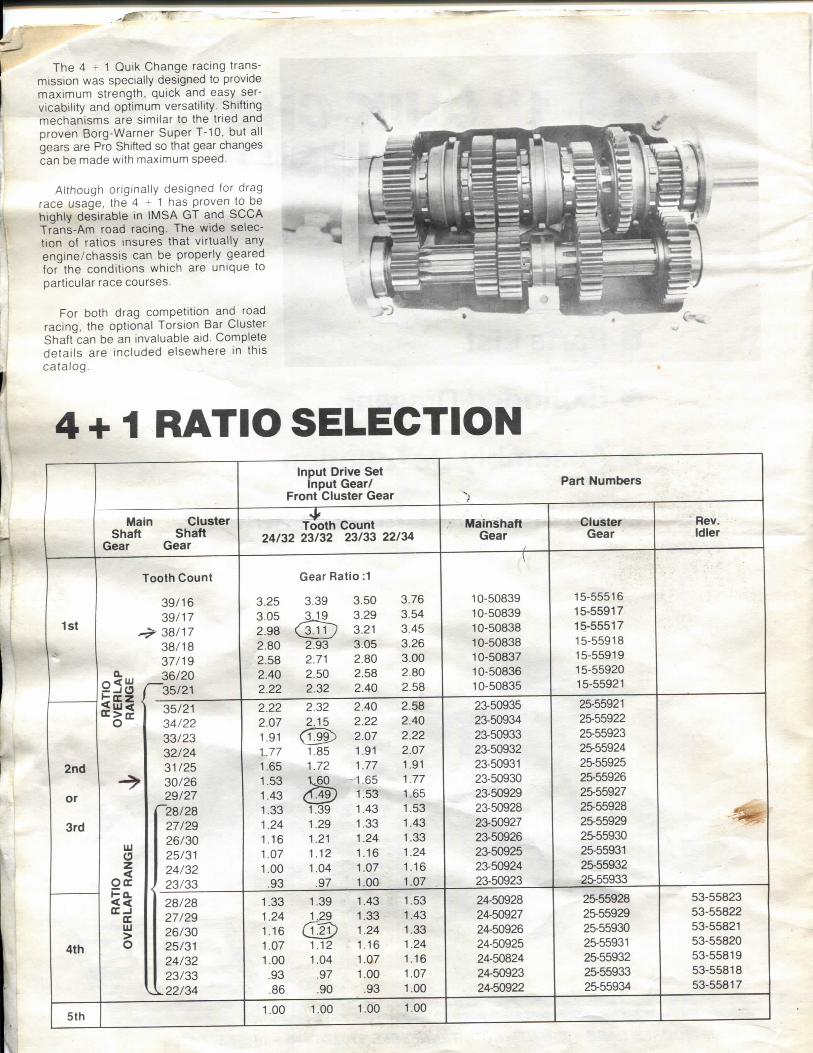
The 4 - 1 Quik Change racing transmission was specially designed to provide maximum strength, quick and easy ser-vicability and optimum versatility. Shifting mechanisms are similar to the tried and proven Borg-Warner Super T-10. but all gears are Pro Shifted so that gear changes can be made with maximum speed.
Although originally designed for drag race usage, the 4 * 1 has proven to be highly desirable in IMSA GT and SCCA Trans-Am road racing. The wide selection of ratios insures that virtually any engine/chassis can be properly geared for the conditions which are unique to particular race courses.
For both drag competition and road racing, the optional Torsion Bar Cluster Shaft can be an invaluable aid. Complete detai ls are included elsewhere in this cata log .
4 + 1 RATIO SELECTION Input Drive Set
Input Gear/ Front Cluster Gear
Part Numbers
Main Cluster Shaft Shaft
Gear Gear Tooth Count
24/32 23/32 23/33 22/34 Malnshaft
Gear Cluster
Gear Rev. Idler
Tooth Count Gear Ratio :1 (
39 /16 3.25 3.39 3.50 3.76 10-50839 15-55516
1st 39 /17 3.05 3 J 9 3.29 3.54 10-50839 15-55917
1st ^ 38 /17 2.98 3.21 3.45 10-50838 15-55517
38 /18 2.80 2.93 3.05 3.26 10-50838 15-55918 37 /19 2.58 2.71 2.80 3.00 10-50837 15-55919
CC>Qr
36/20 2.40 2.50 2.58 2.80 10-50836 15-55920
CC>Qr
1 35 /21 2.22 2.32 2.40 2.58 10-50835 15-55921
CC>Qr 35/21 2.22 2.32 2.40 2.58 23-50935 25-55921 34 /22 2.07 2.15 2.22 2.40 23-50934 25-55922 33 /23 1.91 <T99> 2.07 2.22 23-50933 25-55923 32 /24 1.77 1.85 1.91 2.07 23-50932 25-55924
2nd 31/25 1.65 1.72 1.77 1.91 23-50931 25-55925 -> 30/26 1.53 \30 1.65 1.77 23-50930 25-55926 or 29 /27 1.43 1.53 1.65 23-50929 25-55927
" 2 8 / 2 8 1.33 1.39 1.43 1.53 23-50928 25-55928 3rd 27/29 1.24 1.29 1.33 1.43 23-50927 25-55929
UJ O
26 /30 1.16 1.21 1.24 1.33 23-50926 25-55930 UJ O 25/31 1.07 1.12 1.16 1.24 23-50925 25-55931 z < 24 /32 1.00 1.04 1.07 1.16 23-50924 25-55932
O c bo -< < ( E_l
oc
< 23 /33 .93 .97 1.00 1.07 23-50923 25-55933 O c
bo -< < ( E_l
oc
28/28 1.33 1.39 1.43 1.53 24-50928 25-55928 53-55823
O c bo -< < ( E_l
oc 27 /29 1.24 L 2 9
6 ^ 1.33 1.43 24-50927 25-55929 53-55822
UJ
> 26 /30 1.16
L 2 9 6 ^ 1.24 1.33 24-50926 25-55930 53-55821
4th o 25 /31 1.07 1.12 1.16 1.24 24-50925 25-55931 53-55820 24 /32 1.00 1.04 1.07 1.16 24-50824 25-55932 53-55819 23/33 .93 .97 1.00 1.07 24-50923 25-55933 53-55818
^ 2 2 / 3 4 .86 .90 .93 1.00 24-50922 25-55934 53-55817
5th 1.00 1.00 1.00 1.00

ONE DRAG RACE FIVE-SPEED Part
P R O S H I F T G E A R S Number
1st Gear — Mainshaft 1 0 - 5 0 X X X
1st Cluster Gear 15-55X X X
2nd or 3rd Gear — Mainshaft 2 3 - 5 0 X X X
4th Gear — Mainshaft 2 4 - 5 0 X X X
2nd, 3rd, or 4th Cluster Gear 25-55 X X X
Input Drive Gear (5th) — Take Apart Type 45-50 X X X
Reverse Idler Gear — Rear ^ 5 3 - 5 5 X X X
Input (5th) Cluster Drive Gear (See tielow for Torsion Bar Cluster Gears) 55-55 X X X
'See ratio selection for individual gear part numbers.
Part S E R V I C E P A R T S Number
Input Shaft — G.M. Drag Engines 44-25500
Input Shaft — G.M. Road and Circle Track (1 Ve" 10) 44-25010
Input Shaft — G.M. Road and Cirde Track (IVs -26) 44-25026
Input Shaft — Mopar Engines 44-35500
Input Shaft — Ford Engines 44-45500
Front Reverse Idler Gear (19T) 52-55919A
Pro Shift Hub 1-2 or 3-4 61-90012
Pro Shift Hub 5-Rev 61-90034
Pro Shift Slider 5-Rev 65-50938A
Pro Shift Slider 1-2 or 3-4 65-90500
Shift Arm 3-4 (Without Pin) 66-55034
Shift Arm 1-2 66-92012
Shift Arm 5-Rev 66-92034
Shift Fork All (3 Required) 67-94123
Detent Parts Kit (12 PC) 69-55500
Main C a s e — H.D. (W/O Shift Assembly & Hdware) 71-59003
Extension Housing — Assembly — Std 4+1 72-59003
Extension Housing Assembly — Short Type 72-21003
Main (Output) Shaft f 75-55030
Main (Output) Shaft (32 spline 6M) Short Type 75-55032
Cluster Shaft — S t d 4-1-1 •V6-55010
Cluster Gear Torsion Bar (32TH) 55-56932
Cluster Gear Torsion Bar (33TH) 55-56933
Cluster Gear Torsion Bar (34TH) 55-56934
Torsion Bar Case Bearing (Rear) 78-55207
Reverse Idler Hub 79-55052
Reverse Idler Shaft 77-94114
Roller Bearing — Input Shaft I.D. 78-55112
Ball Bearing — Front Cluster Shaft 78-55207
Ball Bearing — Rear Cluster Shaft (Std) 78-55306
Ball Bearing Main (Output) Shaft 78-94307
Ball Bearing Rear Cluster Shaft (H.D.) 78-55066
Ball Bearing Insput Shaft (Full Shoulder) 78-55607
Roller Bearing — Cluster Center 78-55716
Split Thrust Collar — 4th Gear 80-55400
Small Parts Kit (As Coded) 80-55500
Bearing Retainer Gasket — All Applications 81-95086
Bearing Retainer Seal — All Applications 55-56932
Extension Housing Seal — Output 82-55130
Extension Housing Seal — Output (Short Type) 82-55132
Case Plug Kit (As Coded) 82-55500
Case Plug 3" Dia. 82-56300
Extension Housing Bushing — Replacement 83-55723
Extension Housing Bushing — (Short Type) 82-25732
G.M. Bearing Retainer Assembly — With Gasket and Seal 86-25911
Mopar Bearing Retainer Assembly — With Gasket and Seal 86-35307
Ford Bearing Retainer Assembly — With Gasket and Seal 86-45912
Fastner Kit — All Required Studs, Bolts, Nuts, Washers 90-55500
Part TORSION BAR Number
Torsion Bar Assembly (Complete Kit) 76-56600
Outer Cluster Shaft 76-56610
Inner Cluster Shaft 76-56605
Ball Bearing, Torsion Bar Cluster (Extension Housing) 78-56304
Extension Housing 72-56601
Coupling Sleeve 79-56855
Small Parts Kit 80-56100


ASSEMBLY OF THE DNE 4+1 RACING FIVE-SPEED TRANSMISSION
Proper assembly of the 4 + 1 Quik Change Racing five-speed is critical but not difficult. Use the exploded view on pages 22 and 23 as a reference while fol lowing these instructions and you'll find the " 4 + 1 " the most straightforward transmission you've ever worked on.
NOTE: It's most important to clean and inspect all parts before starting the assembly procedure. Use solvent or degreasing fluid, and blow dry with an air gun.
WARNING: To prevent the spring loaded detent system from coming apart, leave the nuts and washers on the shift arm studs. Re-assembly is difficult.
B. Reverse Idler Sub-Assembly - Slide the front reverse idler gear (rounded teeth forward towards shoulder of idler hub) and the rear reverse idler gear over the Vt" x 3 / i 6 " key. Retain with the 1 % " thin retaining ring. Position the gears and hub between the two bosses in the right case half. Insert the shaft through the access
hole in the front face, and press it through the two bosses after positioning the thrust washers at the front and rear. Lightly tap the end of the shaft to firmly set it in place. Spin the gears to check for free rotation.
C. Front Bearing Retainer Studs - The bolt pattern for Mopar applications differs from GM and Ford. Use the retainer to choose correct 4 holes (with oil slot downward as shown) and install coarse thread end of the four Vie" x IV4" studs. Apply Loctite sealer to all four studs.
T O O L S
The only special tools required are a pair of large retaining ring (Truarc) pliers, a V4" and Vie" Allen wrench and a brass drift. You'll also need a tube of RTV sealant.
O R G A N I Z I N G T H E G E A R S E T
To avoid confusion during assembly, match the mating mainshaft and cluster gears. Using the gear ratio selection chart on page 24, make sure the total number of teeth between each pair is 56 . . . and 51 teeth between the 4th cluster gear and rear reverse idler. Also match the three Pro Shift sleeves with their respective hubs as shown below.
Assembly is considerably easier if mating mam shaft and cluster
Shaft gears IS done prior to beginning.
P R E P A R I N G T H E MAIN C A S E
A. Check Shift Detent System - The shifting mechanism has been fit at the factory for proper function. Each shift arm should rotate from the center neutral position to the two engagement positions, while locking out simultaneous engagement with the other two shift arms.
Before beginning assembly, all parts should be thoroughly cleaned and inspected.
Reverse idler sub-assembly must be installed m case with grooved side of thrust v^asher
facing gears.

C L U S T E R A S S E M B L Y
1. Install roller bearing in center of cluster shaft with 1%-inch retaining rings in grooves on both sides of bearing.
2. Install light duty (1%-inch) retaining ring to retain fourth cluster gear.
3. Install fourth cluster gear with thin shoulder forward.
4. Install light duty (1%-inch) retaining ring on front side of fourth cluster gear.
5. Install light duty (1%-inch) retaining ring in front groove of cluster shaft.
6. Install front cluster gear with undercut toward front and shoulder facing rear.
7. Press front bearing (207) on cluster gear shaft, with retaining ring groove of bearing facing fonward. (Retaining ring is not used in bearing O.D.)
8. Install light duty (1%-inch) retaining rings, front and rear, together with second and third cluster gears. The shoulder side of these gears must face each other for clearance purposes.
9. Install first cluster gear with shoulder facing rearward as shown.
10. Press rear bearing (306) on cluster shaft, with retaining ring toward rear.
11. Install light duty (IVie-inch) retaining ring to retain bearing.
2. Install heavy duty (I'Vie-inch) retaining ring in groove behind second gear position, near middle of mainshaft.
3. Pre-lube first gear O.D. of mainshaft with moly or gear lube.
4. Install first gear from rear of mainshaft, with engagement teeth forward.
5. install thrust spacer and press on bearing (No. 307 non-shielded) with snap ring groove of bearing to rear.
6. Install snap ring (is/s-inch) behind beahng to locate first gear on main-shaft.
7. Check end clearance between first gear and 1-2 hub; .010 to .020-inch is acceptable.
A good pair of retaining ring pliers is a must-
Rings are used to locate gears on cluster sliaft.
8. Install 1-2 slider with beveled nose to rear.
9. Pre-lube second and third gear O.D. of mainshaft with moly or gear lube.
10. Install second gear with engagement teeth to rear.
1 1 . Install third gear with engagement teeth fonward.
12. Install heavy duty (I'Vte-inch) retaining ring in front of third gear.
13. Check end clearance between second and third gear, .015 to .025-inch is acceptable;
14. Install 3 -4 slider with beveled nose fonward.
Front and rear cluster bearings should be pressed on. A rubber mallet may be used for final bearing seating
M A I N S H A F T A S S E M B L Y
1. Check I.D. of each gear and O.D. of matching surface of mainshaft. There should be .002 to .005-inch clearance to allow free spinning.
15. Pre-lube fourth gear O.D. of mainshaft with moly or gear lube.
16. Install fourth gear and split ring thrust collar in groove in front of fourth gear. Retain with heavy duty (1%-inch) retaining ring.
After 1-2 hub is installed, first gear should be placed
on mainshaft from rear
17. Check clearance between fourth gear and thrust collar. .008 to .012-inch is acceptable.
18. Install fifth-reverse hub (6 splines) and slider with shoulder facing to rear. Fork groove in slider should be forward.
19. Install heavy duty (IVs-inch) retaining ring in front of fifth-reverse hub.
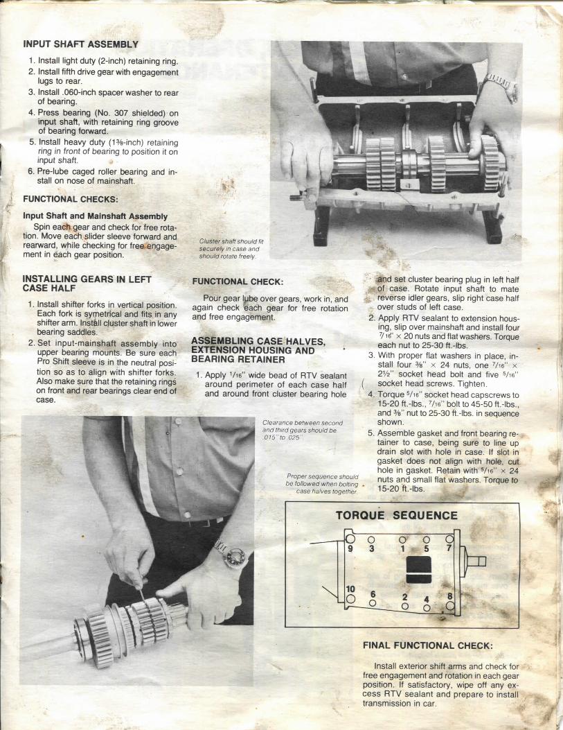
INPUT S H A F T A S S E M B L Y
1. Install light duty (2-inch) retaining ring. 2. Install fifth drive gear w/ith engagement
lugs to rear. 3. Install .060-inch spacer washer to rear
of bearing. 4. Press bearing (No. 307 shielded) on
input shaft, with retaining ring groove of bearing fora/ard.
5. Install heavy duty (1%-inch) retaining ring in front of bearing to position it on input shaft.
6. Pre-lube caged roller tsearing and install on nose of mainshaft.
FUNCTIONAL C H E C K S :
Input Shaft and Mainshaft Assembly Spin each gear and check for free rota
tion. Move each, slider sleeve forward and reanward, while checking for free engagement in each gear position.
Cluster shaft should fit securely in case and should rotate freely.
I N S T A L L I N G G E A R S IN L E F T C A S E H A L F
1. Install shifter forks in vertical position. Each fork is symetrical and fits in any shifter arm. Install cluster shaft in lower bearing saddles.
2. Set input-mainshaft assembly into upper bearing mounts. Be sure each Pro Shift sleeve is in the neutral position so as to align with shifter forks. Also make sure that the retaining rings on front and rear bearings clear end of case.
FUNCTIONAL C H E C K .
Pour gear l^be over gears, work in, and again check each gear for free rotation and free engagement.
A S S E M B L I N G C A S E H A L V E S , E X T E N S I O N H O U S I N G A N D - ' B E A R I N G R E T A I N E R
1. Apply Vie" wide bead of RTV sealant around perimeter of each case half and around front cluster bearing hole
Clearance between second and third gears should be .015-10.025"
Proper sequence should be followed when bolting
case halves together
And set cluster bearing plug in left half ' O i case. Rotate input shaft to mate
reverse idler gears, slip right case half over studs of left case.
!. Apply RTV sealant to extension housing, slip over mainshaft and install four 71^' X 20 nuts and flat washers. Torque each nut to 25-30 ft.-lbs.
!. With proper flat washers in place, install four %" X 24 nuts, one ''/^e" x 2V2" socket head bolt and five Via" socket head screws. Tighten.
L Torque Vie" socket head capscrews to 15-20 ft.-lbs., Vie" bolt to 45-50 ft.-lbs., and %" nut to 25-30 ft.-lbs. in sequence shown.
). Assemble gasket and front bearing re- j tainer to case, being sure to line up drain slot with hole in case. If slot in gasket does not align with hole, cut hole in gasket. Retain with Vie" x 24 nuts and small flat washers. Torque to 15-20 ft.-lbs.
F I N A L F U N C T I O N A L C H E C K :
Install exterior shift arms and check for free engagement and rotation in each gear position. If satisfactory, wipe off any excess RTV sealant and prepare to install transmission in car.
INSTALLATION, OPERATION AND MAINTENANCE
1. Fill transmission with 2V2 quarts of DNE "Pro Shift Lube" (90 weight high performance gear lubricant). Other lubes, additives, etc. are not recommended.
2. Prior to driving, give the transmission a brief run-in with the rear wheels jacked up by operating the transmission a few minutes in each gear. This is mandatory each time the transmission has been apart and a good idea on every race day. Do not Idle or tune in neutral for prolonged periods.
3. Make shifts with quick positive motion. Slow shifting is difficult. For the pits and staging area, select a gear and stay in it.
4. Pro Shift teeth wear-in during the initial
runs. Change the lube after the first 8 to 10 runs and every 30 to 40 runs thereafter.
5. With a proper functioning clutch and good driving technique, the Pro Shift teeth on txjth the sleeve and gear will give long life. But they do wear. If burrs occur on the O.D. of the tooth, they can be dressed periodically with a file or grinder. Pro Shift gear teeth can be replaced as process No. 00-90200.
INSTALLATION
1. Use the mounting specifications illust rated on rear cover, to fabricate mounts, drive shafts, etc.
2. Use of solid engine and rear trans
mission mounts is recommended to min imize clutch l inkage deflection caused by torque reaction.
3. The Hurst and f^r. Gasket shifters and mounting kits specially developed for the "4-1-1" are recommended. Adjust per shifter instructions. Use of the stops is mandatory.
4. Use only top quality clutch components and be sure to eliminate all slop and def lect ion in the linkage. Poor clutch release is the major cause of shifting problems and premature wear with Pro Shift components.
5. If the transmission will be subjected to wet salty atmosphere, paint it with epoxy paint to prevent corrosion of the magnesium.
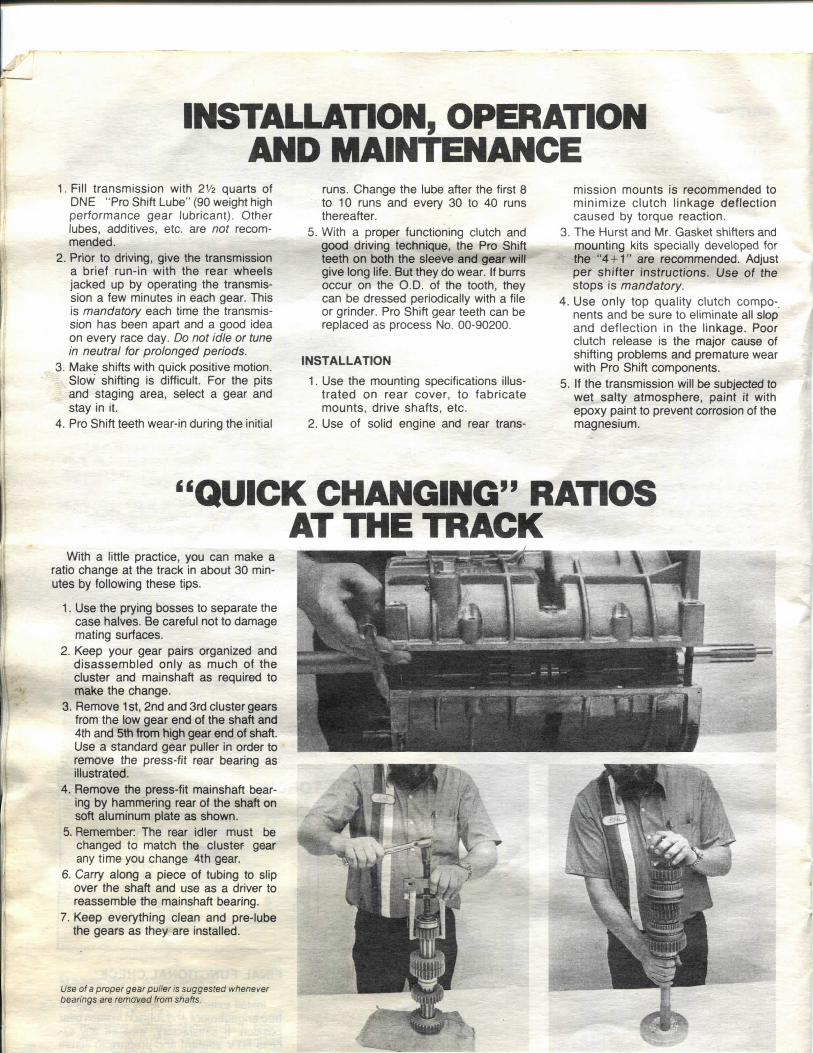
"QUICK CHANGING" RATIOS AT THE TRACK
With a little practice, you can make a ratio change at the track in about 30 minutes by following these tips.
1. Use the prying bosses to separate the case halves. Be careful not to damage mating surfaces.
2. Keep your gear pairs organized and disassembled only as much of the cluster and mainshaft as required to make the change.
3. Remove 1st, 2nd and 3rd cluster gears from the low gear end of the shaft and 4th and 5th from high gear end of shaft. Use a standard gear puller in order to remove the press-fit rear bearing as illustrated.
4. Remove the press-fit mainshaft bearing by hammering rear of the shaft on soft aluminum plate as shown.
5. Remember: The rear idler must be changed to match the cluster gear any time you change 4th gear.
6. Carry along a piece of tubing to slip over the shaft and use as a driver to reassemble the mainshaft bearing.
7. Keep everything clean and pre-lube the gears as they are installed.
Use of a proper gear puller is suggested whenever bearings are removed from shafts.
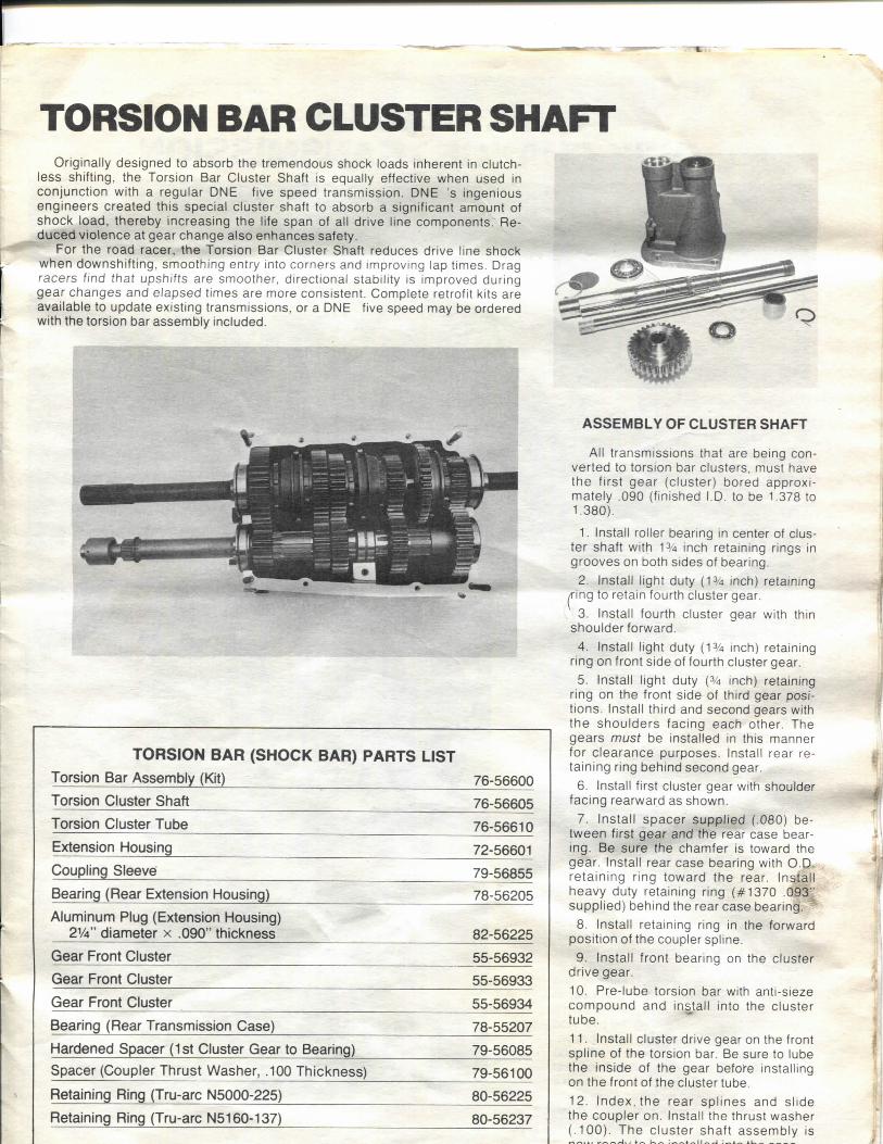
TORSION BAR CLUSTER SHAFT Originally designed to absorb the tremendous shock loads inherent in clutch-
less shifting, the Torsion Bar Cluster Shaft is equally effective when used in conjunction with a regular DNE five speed transmission. DNE 's ingenious engineers created this special cluster shaft to absorb a significant amount of shock load, thereby increasing the life span of all drive line components. Reduced violence at gear change also enhances safety.
For the road racer, the Torsion Bar Cluster Shaft reduces drive line shock when downshift ing, smoothing entry into corners and improving lap times. Drag racers find that upshifts are smoother, directional stability is improved during gear changes and elapsed times are more consistent. Complete retrofit kits are available to update existing transmissions, or a DNE five speed may be ordered with the torsion bar assembly included.
T O R S I O N B A R ( S H O C K B A R ) P A R T S L I S T
Torsion Bar Assembly (Kit) 76-56600
Torsion Cluster Shaft 76-56605
Torsion Cluster Tube 76-56610
Extension Housing 72-56601
Coupling Sleeve 79-56855
Bearing (Rear Extension Housing) 78-56205
Aluminum Plug (Extension Housing) 21/4" diameter x .090" thickness 82-56225
Gear Front Cluster 55-56932
Gear Front Cluster 55-56933
Gear Front Cluster 55-56934
Bearing (Rear Transmission Case) 78-55207
Hardened Spacer (1st Cluster Gear to Bearing) 79-56085
Spacer (Coupler Thrust Washer, .100 Thickness) 79-56100
Retaining Ring (Tru-arc N5000-225) 80-56225
Retaining Ring (Tru-arc N5160-137) 80-56237
A S S E M B L Y O F C L U S T E R S H A F T
All transmissions that are being converted to torsion bar clusters, must have the first gear (cluster) bored approxi mately .090 (finished I D . to be 1.378 to I . 380).
1. Install roller bearing in center of cluster shaft with 13/4 inch retaining rings in grooves on both sides of bearing.
2. Install light duty ( 1 % inch) retaining ^ing to retain fourth cluster gear.
3. Install fourth cluster gear with thin shoulder forward.
4. Install light duty ( 1 % inch) retaining ring on front side of fourth cluster gear.
5. Install light duty (% inch) retaining ring on the front side of third gear positions. Install third and second gears with the shoulders facing each other. The gears must be installed in this manner for c learance purposes. Install rear retaining ring behind second gear.
6. Install first cluster gear with shoulder facing rearward as shown.
7. Install spacer suppl ied (.080) between first gear and the rear case bearing. Be sure the chamfer is toward the gear. Install rear case bearing with O.D-retaining ring toward the rear. Install heavy duty retaining ring (#1370 .093" supplied) behind the rear case bearing.
8. Install retaining ring in the forward position of the coupler spline.
9. Install front bearing on the cluster drive gear. 10. Pre-lube torsion bar with anti-sieze c o m p o u n d and install into the cluster tube. I I . Install cluster drive gear on the front spline of the torsion bar. Be sure to lube the inside of the gear before installing on the front of the cluster tube. 12. Index, the rear spl ines and slide the coupler on. Install the thrust washer ( .100) . The c luster shaft assembly is