
3to5axis
31
Automatic 3- to 5-Axis Machining Version 2.4 1 Introduction The use of 3-axis toolpaths is sufficient as long as the part is not very deep in relation to the cutter diameter. If the part is very deep and/or has narrow cavities the usage of pure 3-axis toolpaths is not sufficient for the complete finishing process of the part. Especially, if hard material has to be milled the usage of long cutters results in a bad surface quality. For that reason the spindle is angled in a way that a specific region of the part can be reached with a shorter tool. The process of setting a constant angle to the spindle and machining with this angle is well known as 3+2-axis machining. However, if the part consists of many such regions or if collisions are likely to happen it is necessary to create many small toolpaths for different axis positions. This is time consuming, needs much manual interaction and is an error-prone process. In order to overcome the drawbacks of 3+2-axis machining new strategies for 5-axis toolpaths have been developed. This works fine for special purpose strategies like rolling and profiling or for parts having a special shape such as cylindrical geometries. However, up to now a fully automatic general solution for the calculation of collision free 5-axis toolpaths does not exist. In 5-axis toolpath creation the biggest challenge is not the cutter movement itself but the axis angles and the collision avoidance. A smooth variation of the axes along the toolpath while anticipating the next cavity or corner is very important for the milling machine and the resulting surface quality. Moreover the kinematics of the milling machine needs to be taken into consideration because most of the existing 5-axis milling machines are limited in its rotation axes. The knowledge of these limitations has to be taken into consideration while the toolpath is being calculated. With Automatic 3- to 5-Axis Machining (modules 3to5axis and 5tomachine) Sescoi presents a fully automatic 5-axis toolpath strategy which takes as input an arbitrary 3+2-axis finishing toolpath and calculates a collision free 5-axis toolpath by considering the machine’s angle limits. In addition the user can influence the resulting toolpath in many ways by setting various parameters. The final toolpath is smooth, holder collision free and respects the machine angle limits. Future developments will also include the full kinematics of the machine during the calculation. Currently the kinematics of the machine can be checked within VisuNC. The 3- to 5-axis machining process works in two steps. 1. The first step uses the module 3to5axis which takes a 3+2-axis toolpath and calculates a 5-axis toolpath by avoiding collisions. If a collision can not be avoided this position is marked. This process does not depend on the machine. 2. The second step uses the module 5tomachine which takes the output of 3to5axis and considers the machine angle limits. This process depends on the machine. All positions of the toolpath which have a collision are cut out from the resulting toolpath.
-
Upload
amy-erickson -
Category
Documents
-
view
9 -
download
0
Transcript of 3to5axis

Automatic 3- to 5-Axis Machining
Version 2.4
1 Introduction The use of 3-axis toolpaths is sufficient as long as the part is not very deep in relation to the cutter diameter. If the part is very deep and/or has narrow cavities the usage of pure 3-axis toolpaths is not sufficient for the complete finishing process of the part. Especially, if hard material has to be milled the usage of long cutters results in a bad surface quality. For that reason the spindle is angled in a way that a specific region of the part can be reached with a shorter tool. The process of setting a constant angle to the spindle and machining with this angle is well known as 3+2-axis machining. However, if the part consists of many such regions or if collisions are likely to happen it is necessary to create many small toolpaths for different axis positions. This is time consuming, needs much manual interaction and is an error-prone process.
In order to overcome the drawbacks of 3+2-axis machining new strategies for 5-axis toolpaths have been developed. This works fine for special purpose strategies like rolling and profiling or for parts having a special shape such as cylindrical geometries. However, up to now a fully automatic general solution for the calculation of collision free 5-axis toolpaths does not exist. In 5-axis toolpath creation the biggest challenge is not the cutter movement itself but the axis angles and the collision avoidance. A smooth variation of the axes along the toolpath while anticipating the next cavity or corner is very important for the milling machine and the resulting surface quality. Moreover the kinematics of the milling machine needs to be taken into consideration because most of the existing 5-axis milling machines are limited in its rotation axes. The knowledge of these limitations has to be taken into consideration while the toolpath is being calculated.
With Automatic 3- to 5-Axis Machining (modules 3to5axis and 5tomachine) Sescoi presents a fully automatic 5-axis toolpath strategy which takes as input an arbitrary 3+2-axis finishing toolpath and calculates a collision free 5-axis toolpath by considering the machine’s angle limits. In addition the user can influence the resulting toolpath in many ways by setting various parameters. The final toolpath is smooth, holder collision free and respects the machine angle limits. Future developments will also include the full kinematics of the machine during the calculation. Currently the kinematics of the machine can be checked within VisuNC.
The 3- to 5-axis machining process works in two steps.
1. The first step uses the module 3to5axis which takes a 3+2-axis toolpath and calculates a 5-axis toolpath by avoiding collisions. If a collision can not be avoided this position is marked. This process does not depend on the machine.
2. The second step uses the module 5tomachine which takes the output of 3to5axis and considers the machine angle limits. This process depends on the machine. All positions of the toolpath which have a collision are cut out from the resulting toolpath.

2
Note: The module 5tomachine can also be used for standard 5-axis toolpaths in order to consider the machine’s angle limits.
Note: It is important to understand that 3to5axis does not depend on the machine while 5tomachine does depend on the machine. The calculation time of 3to5axis is much higher compared to the time of 5tomachine. Hence, it is recommended to choose the parameters of 3to5axis very carefully. For the module 5tomachine a milling machine has to be chosen. Afterwards it can easily be replaced by another machine.
The following sketch shows the workflow of a 3+2-axis or 5-axis standard WorkNC toolpath through the automatic 3- to 5-axis machining conversion process.
2 The User Interface The following picture shows the user interface of Automatic 3-Axis to 5-Axis Machining. Below the caption, which includes the project path, the list of the current toolpaths is shown. The columns give information about some toolpath parameters and the WorkNC calculation status (C+/-), the 3to5axis status (5x+/-) and the 5tomachine status (5m+/-). Column H indicates if a holder is chosen for the toolpath. To choose a holder is mandatory for both modules 3to5axis and 5tomachine but it does not need to be calculated. Column either shows the tool length in black or the minimum save tool length in red.
Note: The minimum save tool length is only valid for the calculated toolpath. It means that the calculated toolpath is collision free for the minimum save tool length. But it is not the global minimum save tool length (the minimum of all minimum save tool lenghts of all possible toolpaths). As a consequence, it is possible that another 5-axis toolpath exists which has a shorter minimum save tool length.
Example: Suppose a tool with tool length 10mm and a calculated 5-axis toolpath with a minimum save tool length of 12.5mm. It means that the converted 5-axis toolpath is collision free with the given tool and a tool length of 12.5. But it could be that if you would recalculte the toolpath conversion with a tool length of 11mm the result could be collision free.
WorkNC Automatic 3- to 5-Axis Machining
WorkNC 3+2-Axis Toolpath
Module 3to5axis (Machine independent)
Module 5tomachine (Machine dependent)
WorkNC 5-Axis Toolpath
WorkNC Standard 5-Axis Toolpath

3
Below the toolpath list the currently selected toolpath and the view angle are found. The view angle is the angle of the view’s Z-axis to the machine axis. The “Extra…” buttons starts a
dialog with additional parameters for the calculation process. By pressing the icon the
current version information will be displayed. The icon starts this document as a pdf- file. The group boxes below represent the specified 5-axis parameters. All parameters for 3to5axis are found in the group box “3 To 5-Axis Strategy” while the 5tomachine parameters are in the group box “Machine Limits Collision Check”.
The user interface of Automatic 3- to 5-Axis Machining.
All parameters which are set to a specific toolpath are saved with the toolpath. Hence it is possible to prepare multiple toolpaths for the calculation process. The “Calculate…” button saves all parameters and starts the calculation of all toolpaths which have a 5x- or 5m- flag.
By pressing “Reread” the project is reread from disk. This is useful if the WorkNC project has been changed while the interface is running.
Note: Take care of saving the current 5-axis parameters of all toopaths. E.g. if the toolpath numbering has changed in WorkNC because of a toolpath insertion while the 5-axis interface is still running you will write the settings to the wrong toolpaths. In order to avoid such situation we recommend to close the interface whenever you add, change or insert new toolpaths in the menu.

4
3 Conversion of 3- to 5-Axis Toolpaths The following pictures show the currently available six different main strategies which can be used for a 3- to 5-axis toolpath conversion:
Vertical Constant to Axis Normal To Surface
No Change Constant (Attracting) Constant (Repulsive)
It is important to note that each of these strategies only give a recommendation to the calculation. If it turns out that using this recommendation the tool or holder would collide with the geometry the algorithm searches for the closest non colliding position. If such a position can not be found the point is marked as a colliding point. The user can see these marks within the VisuNC.
Toolpath points for which a collision free axis position could not be found are marked with red circles.
To avoid collisions is a complex and time consuming process which has to be done for every point of the toolpath. Hence, the whole calculation process can be sped up by choosing the optimal strategy and within the strategy the optimal set of parameters.
5
For example if along a vertical wall the recommendation would be to start with a vertical axis each point would have a collision and for each point several collision avoidance tests would need to be done. By directly starting with an angled axis the process could avoid this and work be much faster.
3.1 3- to 5-Axis Strategies Six different main strategies are currently available. Common for all strategies is that their parameters either refer to the chosen machine axis System or refer to the view axis system. From this axis system we usually only need the Z-axis. For that reason we define:
• Machine Axis: Z-axis of the chosen machine axis system • View Axis: Z-axis of the chosen view system
As common term for one of those axes we use Reference Axis.
3.1.1 Vertical
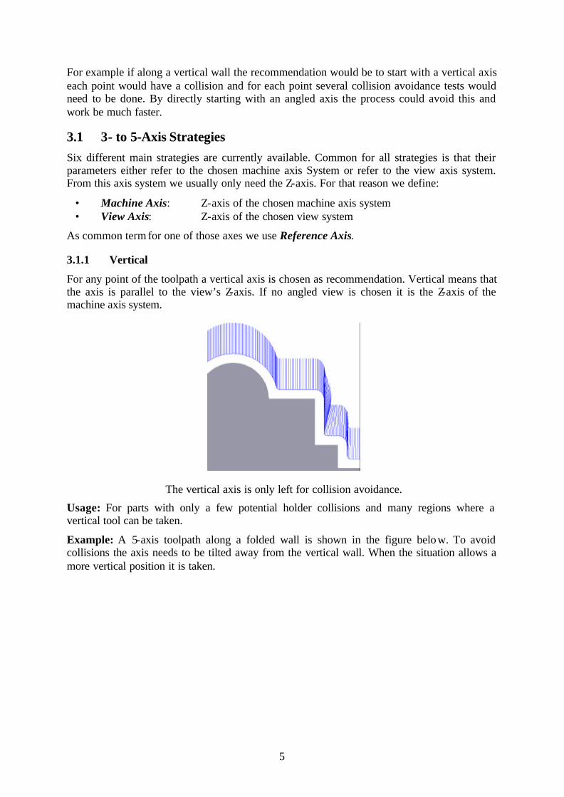
For any point of the toolpath a vertical axis is chosen as recommendation. Vertical means that the axis is parallel to the view’s Z-axis. If no angled view is chosen it is the Z-axis of the machine axis system.
The vertical axis is only left for collision avoidance.
Usage: For parts with only a few potential holder collisions and many regions where a vertical tool can be taken.
Example: A 5-axis toolpath along a folded wall is shown in the figure below. To avoid collisions the axis needs to be tilted away from the vertical wall. When the situation allows a more vertical position it is taken.

6
Toolpath along a folded vertical wall.
3.1.2 Constant to Axis For any point of the toolpath we choose an axis which has a constant angle to the machine’s or view’s Z-axis. It is done by determining the plane defined by the Z-axis and the normal vector of the surface for that point. Within this plane we choose as axis recommendation a vector which has a constant angle to the Z-axis.
Axes with a constant angle to the Z-axis.
Usage: Used for Z- level finishing toolpaths and parts for which the A or B axis can remain constant in many regions.
Note: The user must take care about regions of the surface which are vertical to the reference axis. Here the normal vector has the same direction as the referring axis. As a result we are not able to find a unique plane in which we can tilt the axis to the constant value. For such regions the strategy will set the axis recommendation along the reference axis:

7
All axes A have a constant angle to the reference axis R, independent on the surface normal. The axes B are parallel to R because the corresponding surfaces
are vertical to the reference axis R.
Example 1: A Z- level finishing toolpath around a mould with a constant angle.
Keeping a constant machining angle A or B.
3.1.3 Normal To Surface For any point of the toolpath an axis along the normal vector of the surface is chosen. To be more precise we choose an axis in the plane given by the Z-axis and the normal vector. The
R
B A
A
A
B A
A
A

8
position within the plane is determined by parameters which are discussed later. Due to its variety of parameters Normal to Surface becomes one of the most powerful and flexible strategies.
Following the pure normals of a surface result in much movement while a restriction of the axis to a maximum angle has less movements:
Using the pure normals of a surface as axis recommendation and bending them up to 45°.
Usage: For parts with steep and vertical walls (e.g. for Z- level finishing toolpaths) the strategy can be adapted so that the A/B angle remain as constant as possible. For slightly bent regions (e.g. for planar finishing toolpaths) the strategy is able to follow exactly the normals of the surface.
Note: The first two strategies “Vertical” and “Constant to Axis” are special cases of “Normal to Surface”. It means that by setting the parameters in a specific way we exactly obtain either “Vertical” or “Constant to Axis” (see section 3.2 for more details).
Note: The user must take care about regions of the surface which are vertical to the reference axis. Here the normal vector has the same direction as the referring axis. As a result we are not able to find a unique plane in which we can tilt the axis to the constant value. For such regions the strategy will set the axis along the reference axis.
Example 1: The second example shows a movement following exactly the surface normal.

9
Following the surface normals.
3.1.4 No Change For any point of the toolpath the next axis recommendation depends on the current situation. For longer convex movements it follows the normal of the surface and for concave movements the previous axis is chosen.
Axes are kept if possible.
Usage: For remachining of parts and concave regions.
10
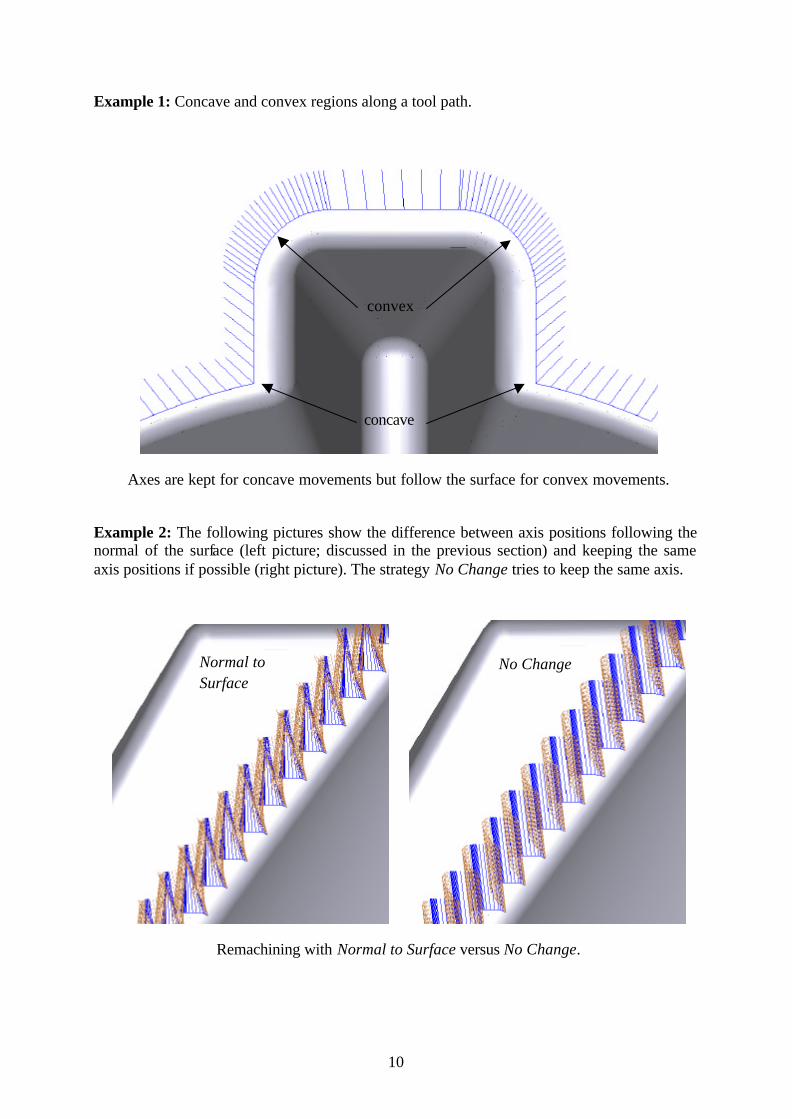
Example 1: Concave and convex regions along a tool path.
Axes are kept for concave movements but follow the surface for convex movements.
Example 2: The following pictures show the difference between axis positions following the normal of the surface (left picture; discussed in the previous section) and keeping the same axis positions if possible (right picture). The strategy No Change tries to keep the same axis.
Remachining with Normal to Surface versus No Change.
No Change Normal to Surface
concave
convex

11
3.1.5 Constant (Attracting) For any point of the toolpath an axis with a constant angle to the machine’s or view’s Z-axis is chosen. The direction of the axis is defined either by the shortest distance to an attraction point or an attraction curve. If more than one attraction point is chosen a mean direction considering all points is calculated. The attraction curve does not need to be closed and can consist of several sub-curves. The Z-height of the point or curve is not taken into consideration.
The advantage of using attraction points/curves is that compared to Normal to Surface the axes are always directed to the attraction item. As a result the axes have fewer variations along the toolpath which helps stabilizing the machine.
Machining a hemisphere cavity with a single attraction point in the center and left of the center.
Toolpath for an attraction line and a closed attraction curve.
Usage: For z-level finishing toolpaths and (cavity) parts with heavily steep and varying surfaces.
Note: The user must take care about regions which are directly underneath the attraction items. For such points the algorithm still decides the direction in which the axis must be tilted until the constant angle is reached. Here it can potentially happen that consecutive points have an opposite constant angle.
In addition it is also possible to define more than one attraction point. The meaning is that for any toolpath point the closest attraction point is the most important one and has the biggest influence on its axis. The picture below shows a toolpath having three attraction points.
12
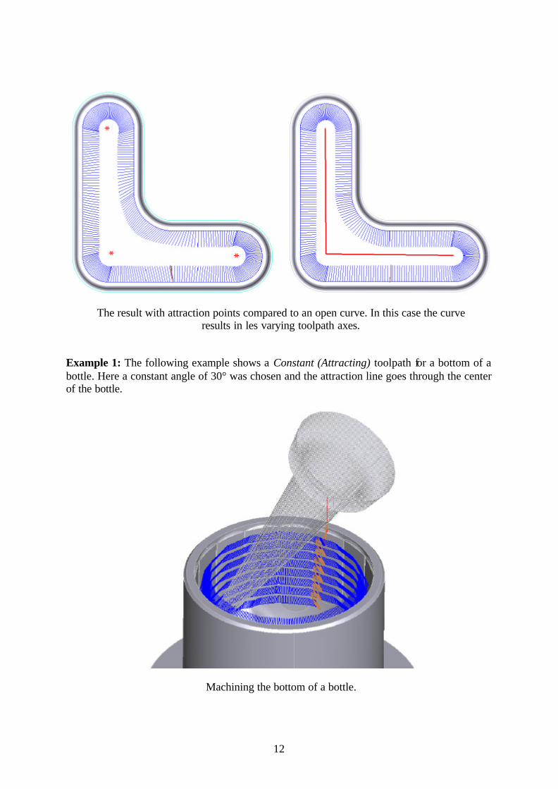
The result with attraction points compared to an open curve. In this case the curve results in les varying toolpath axes.
Example 1: The following example shows a Constant (Attracting) toolpath for a bottom of a bottle. Here a constant angle of 30° was chosen and the attraction line goes through the center of the bottle.
Machining the bottom of a bottle.

13
3.1.6 Constant (Repulsive) The strategy Constant (Repulsive) works exactly in the same way as Constant (Attracting) but use the opposite angle direction. Now the axes are not attracted by points or curves but repulsed by them. For any point of the toolpath an axis with a constant angle to the machine’s or view’s Z-axis is chosen. The direction of the axis is defined either by the shortest distance to a repulsive point or a repulsive curve. If more than one repulsive point is chosen a mean direction considering all points is calculated. The repulsive curve does not need to be closed and can consist of several sub-curves. The Z-height of the point or curve is not taken into consideration. In contrast to Constant (Attracting) we are usually machining die- like parts.
Machining a hemiellipse with a repulsive point and curve.
A straight line as repulsive curve.
Usage: For z- level finishing toolpaths and (die) parts with heavily steep and varying surfaces. Note: The user must take care about regions which are directly underneath the attraction
items. For such points the algorithm still decides the direction in which the axis must be tilted until the constant angle is reached. Here it can potentially happen that consecutive points have an opposite constant angle.

14
Example 1: The example below shows the machining of a hemisphere by using a single repulsive point. The constant angle is 20°.
Machining a hemisphere with a single repulsive point.
Example 2: The second example shows the toolpath for an inclined cone on a plane. A single repulsive point at the top of the cone was chosen by using a constant angle of 20°. the reference axis is the machine’s Z-axis, so that the A/B angle remains constant.
Machining an inclined cone with a single repulsive point.
3.2 Strategy dependent Parameters Additional parameters can be used to influence the 5-axis toolpath generation. Some of them are applicable to all strategies and some are specific. The following table gives an overview of which parameters are applicable to what strategy:

15
Vertical Constant to Axis
Normal to Surface
No Change Constant (Attracting)
Constant (Repulsive)
Machine Axis, ViewAxis
View Machine, View
Machine, View
Machine, View
Machine, View
Machine, View
Maximum Vertical Angle ü ü ü ü
Minimum Normal Angle ü ü
Maximum Normal Angle ü ü
Maximum Allowed Angle ü ü ü ü ü ü
Forward Angle ü ü ü ü ü ü
Constant Angle ü ü ü
Remove Unnecessary Points ü ü ü ü ü ü
Maximum Angle Distance ü ü ü ü ü ü
Keep Axis along Machining Direction
ü ü ü
The meaning of the different parameters is given below:
• Machine Axis, View Axis: With the parameter Machine Axis or View Axis the user can define the reference axis system. If the machine is chosen, all angle values (discussed below) will be referred and measured with respect to the machine’s Z-axis. If the view of the toolpath is chosen the view’s Z-axis will be the reference axis.
Note: The machine’s Z-axis is the Z-axis of the coordinate system which was chosen in VisuNC as the machine system. It usually corresponds to the milling machine’s Z-axis but it must not necessarily be the case.
Reference axis is the machine’s Z-axis or the view’s Z-axis depending on if the toolpath is created vertically or with a view.

16
The first picture shows the situation for the machine’s Z-axis. Angle P is 25° and is measured from the machine axis which always is vertical. The second picture refers to a toolpath which has a view under 55° with respect to the machine axis. Now, the angle P is measured from the view and has because of this an angle of 80° from the machine axis.
A different situation is given if the toolpath is created with a view but the machine’s Z-axis is taken as reference. It means that independent from the view all angles will be referred to the machine axis. The picture shows a toolpath with a 55° view and referring all axes to the machine axis.
Reference axis is the machine’s Z-axis although the toolpath is created with a view.
Note: The third case is important when undercuts are to be machined. For undercuts the toolpath must be created with a view. If then the machine is taken as refe rence we are still able to keep one angle of the machine axes (A or B) constant:
Undercut machining with a 55° view. Strategy is Constant to Axis with 55° and refering to the machine’s Z-axis.

17
• Maximum Vertical Angle V: If the surface normal vector of a given toolpath point has an angle which is smaller than the maximum vertical angle V then the axis recommendation is set to vertical.
Maximum Vertical Angle V of 10° and 30°.
• Minimum Normal Angle M: If the surface normal vector of a given toolpath point
has an angle which is smaller than the minimum normal angle M but bigger than the maximum vertical angle V then the axis is set to M.
• Maximum Normal Angle N: If the surface normal vector of a given toolpath point has an angle which is smaller than the maximum normal angle N but bigger than the minimum, normal angle M then the axis is set to the normal vector. If the angle is bigger than N the axis is set to N.
Minimum Normal Angle M of 20° and 40°. N has 60°.
Note: By setting the minimal normal angle M to the maximal normal angle N it is possible to achieve a constant angle for all surface normals. The only exception is for plane regions having a vertical normal. Here the vertical axis is kept. This is exactly what strategy Constant to Axis does.

18
Achieving a constant axis angle by setting e.g. M and N to 45°.
Note: By setting V = M = N = 0 we achieve the strategy Vertical.
• Constant Angle P: For the strategies Constant to Axis, Constant (Attracting) and Constant (Repulsive) the constant angle P defines the angle to the referring axis (machine or view). In addition Constant (Attracting) and Constant (Repulsive) allow the use of a maximum vertical Angle V.
Constant to Axis with angle P of 25°.
Constant (Attracting) and Constant (Repulsive) with an angle P of 25°.

19
• Maximum Allowed Angle A: Any angle which is achieved during the 3to5axis calculation process is cut by the maximum allowed angle. As a result the 5-axis toolpath will not have any axis having an angle bigger than the maximum allowed angle. All other angles must be smaller than A. If a collision could only be avoided by taking a bigger angle the corresponding point will be marked and cut out by 5tomachine.
• Lead Angle: Choosing an positive lead angle forces a tilting of all axes in the direction of the tool movement.
Toolpath with lead angle 0° and 15°.
3.2.1 Additional Parameters Additional parameters which are usually used not that frequently are found in the dialog “Additional Parameters” by pressing the button “Extra…”:
The “Additional Parameters” dialog.
• Maximum Angle Distance: For all 3to5axis strategies and 5tomachine it is possible to define a maximum angle distance. By setting this value e.g. to 5° the 3- to 5-axis machining calculation ensures that each consecutive pair of axes has an angle less than 5°. If it happens during the calculation that a pair has more than 5° additional points and axes will be inserted.
• Remove Unnecessary Points: The check box “Remove Unnecessary Points” is applicable for both 3to5axis and 5tomachine. If the box is checked all points within a 5-axis toolpath lying on a straight line and having the same axis are removed from the toolpath. This options is important for machines and controllers which need a continuous flow of points.

20
5-axis toolpath with all points and with removal of unnecessary points.
• Keep Axis Along Machining Direction: All the parameters discussed in the previous section are dealing with angles referring to a reference axis. Especially the constant strategies have the goal to keep the A/B axis constant. The opposite can be done by trying to keep the C axis constant and vary only A/B. This can be achieved by choosing the option “Keep Axis Along Machining Direction” which is applicable for the strategies Normal to Surface, Constant (Attracting) and Constant (Repulsive). It is defined as the toolpath’s machining direction and has the meaning that all axes are kept in the plane which is defined by the reference axis (machine or view) and the machining direction. The A/B angle is kept during this operation.
Keeping the axes along the machining direction.
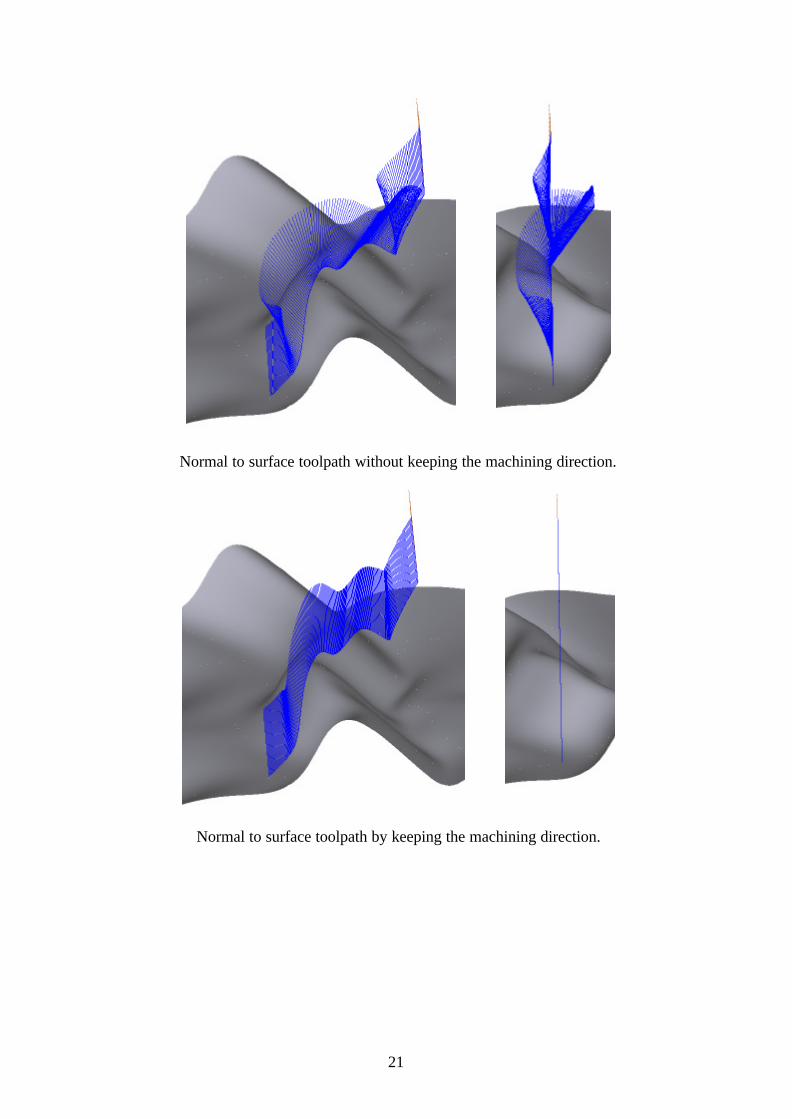
The pictures below show the difference for a finishing toolpath which follows the surface normal up to an angle of 40°.
The first pair of pictures show the standard case without the option “Keep Axis Along Machining Direction”. If you look straightly along the machining direction you can see the deviation from the machining direction.
The second pair of pictures was calculated with “Keep Axis Along Machining Direction” and an angle of 0°. We need 0° here because the toolpath uses an angled view and the machining direction always is referred to the view. For that reason we also have to choose “View Axis” as reference axis. The picture along the machining direction shows now that all axes are lying in the plane defined by the machining direction and the view’s Z-axis.
21
Normal to surface toolpath without keeping the machining direction.
Normal to surface toolpath by keeping the machining direction.
22
4 Machine Limits Collision Check The module 5tomachine takes as input a 5-axis toolpath which either stems from the 3to5axis module or a WorkNC standard 5-axis strategy such as 5-Axis Rolling or 5-Axis Profile. If the input stems from 3to5axis it is ensured that the output of the module is a collision free 5-axis toolpath. All collisions which could not be avoided are cut out. The only thing the user has to do is to choose a milling machine.
Colliding points or points leading the machine out of its angle limits can stem from different situations and are handled differently.
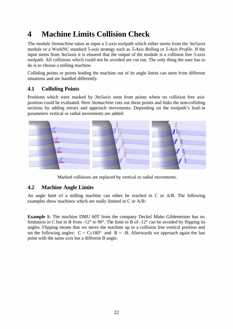
4.1 Colliding Points Positions which were marked by 3to5axis stem from points where no collision free axis position could be evaluated. Here 5tomachine cuts out these points and links the non-colliding sections by adding retract and approach movements. Depending on the toolpath’s lead- in parameters vertical or radial movements are added:
Marked collisions are replaced by vertical or radial movements.
4.2 Machine Angle Limits An angle limit of a milling machine can either be reached in C or A/B. The following examples show machines which are really limited in C or A/B:
Example 1: The machine DMU 60T from the company Deckel Maho Gildemeister has no limitation in C but in B from -12° to 90°. The limit in B of -12° can be avoided by flipping its angles. Flipping means that we move the machine up to a collision free vertical position and set the following angles: C = C±180° and B = -B. Afterwards we approach again the last point with the same axis but a different B angle.

23
The milling machine DMU 60T.
Example 2: The machine FZ40 from the company Zimmermann has a limitation in C from -200° to 200° and in A from -95° to 95°. The limit in C can be avoided by unwinding the machine by 360°. Flipping could also solve the limitation in this case since it would only be unwinded by 180°. Which strategy is chosen depends on the overall range in C.
The milling machine FZ40.
4.2.1 Reaching the Limits in C The following pictures show the situation of a machine which is limited in C from -360° to 360°. Whenever the limit is reached 5tomachine retracts to a vertical position and unwinds the machine by 360°. Since a vertical axis given by its coordinates ( 0, 0, 1) can not represent any C angle 5tomachine actually writes angles to the 5-axis toolpath. Doing this makes the toolpath unique to the machine under consideration. It then becomes a machine dependent toolpath. That the toolpath includes angle points is visualized with VisuNC by marking them with a white circle. Depending on the toolpath’s lead- in parameters vertical or radial approaches are added while the machine is moved to a vertical position.

24
Avoiding the angle limits in C by unwinding the spindle.
The situation becomes even more difficult if the axes for A and C or B and C are not independent. This is the case for machines having an angle of 45° between its axes. Any movement around the X- or Y-axis will change both the A or B and the C angle. Thus, in order to be able to move to a vertical position it is necessary that we also have enough freedom in C to reach it without touching the limit in C. More generally does in mean that the angle limit in C is a function of A or B. The module 5tomachine solves this problem by keeping a dynamic angle limit of the C axis.
Example 1: The following pictures show the same toolpath for a milling machine with independent and dependent B and C angles. Both machines are configured to have a C Limit from -360° to 360°. The left picture shows the independent case. Whenever the -360° degrees are reached the machine moves up and unwinds itself. The independency of the axes leads to the same unwinding position along the whole toolpath. The right pictures shows the dynamic case where the C limit depends on the current B angle. The bigger B becomes the earlier the limit in C will be reached. This becomes visible by a varying unwinding position.
Unwinding positions for machines with independent and dependent axes.

25
Example 2: The Machine DMU 125 P from the company Deckel Maho Gildemeister is an example of such a case. Here the axes for B and C are not independent because they build an angle of 45°. In this case the angle limit in C is a function of B.
The milling machine DMU 125 P.
4.2.2 Reaching the Limits in A/B If it happens that the machine reaches an angle limit in A or B, 5tomachine moves up to a vertical position and flips the angles. Flipping means that we
• choose the opposite B angle: B = -B and
• turn the C angle by 180°: C = C+180 or C = C-180.
Afterwards we approach again the last point with the same axis direction but a different B angle. Again, depending on the toolpath’s lead- in parameters vertical or radial approaches are added while the machine is moved to a vertical position
Avoiding the angle limits in A/B by flipping the angles.

26
Sometimes it is possible to solve the limitation in A/B by looking far ahead. If 5tomachine detects that we are going to reach a limit in A/B and if we are currently vertical we do the C manipulation immediately within the next points (C = C+180 or C = C - 180). Since we are currently vertical (A = B = 0) the flipping of A/B remains 0. The benefit of this procedure is that we do not need to retract from the surface.
Avoiding the angle limits in A/B by anticipation.
4.3 Machine Limits for Standard 5-Axis Toolpaths For WorkNC standard 5-axis toolpaths the module 5tomachine can also be used to avoid the machine limitations. In this case the user interface “3 To 5-Axis Strategy” is disabled.
4.4 Saving the Colliding Points in a split toolpath. Toolpath points which were marked by 3to5axis or cut by 5tomachine can be saved in a split toolpath. For the splitting you must follow the following rules:
• Define Toolpath in WorkNC (e.g. number 10). • Specify holder and choose “Save both sections” as collision detection type(toolpath
10.1 is created). • Calculate toolpath, holder and splitted toolpath completely in WorkNC. • Start the 3- to 5-axis machining interface and choose your 3to5axis and 5tomachine
parameters for the main strategy (10). Choose “Save both sections” in the “Machine Limits Collision Check” group box. Do not specify any option for the split toolpath (10.1).
• Start the calculation. • After running 5tomachine on the toolpath (10) the split toolpath (10.1) will hold the
cut part of the original toolpath as a standard 3-axis toolpath. The M- flag in WorkNC indicates then that the toolpath has been modified.
Note: The module 3to5axis will always use the original full 3-axis toolpath even if the calculation has already split the 3-axis toolpath.
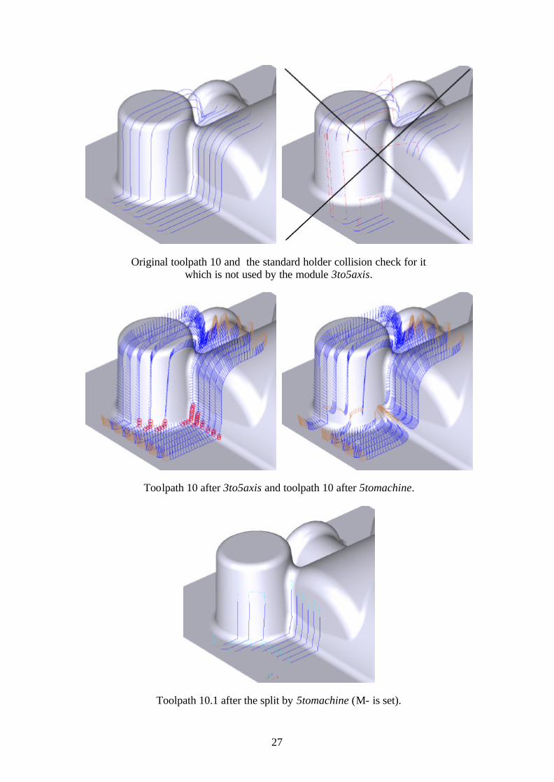
Example: The following example shows all different steps for the example toolpath 10 and the split toolpath 10.1.
27
Original toolpath 10 and the standard holder collision check for it which is not used by the module 3to5axis.
Toolpath 10 after 3to5axis and toolpath 10 after 5tomachine.
Toolpath 10.1 after the split by 5tomachine (M- is set).

28
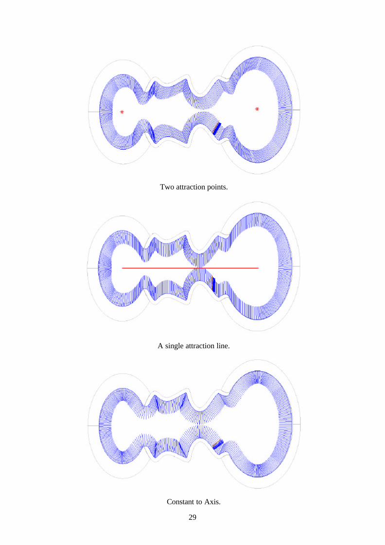
5 Comparing Examples 5.1 Constant (Attracting) and Constant to Axis The following example shows a conical/cylindrical part which has a heavily folded middle part:
A part with a heavily folded middle.
The next three pictures show the differences of the axes if the toolpath is converted with two attraction points, an attraction line and with the strategy Constant to Axis. Depending on the user’s needs he can choose between the different possibilities:
If a minimum of axis variations is wished the attraction line is probably the best choice since the axis recommendation does not care about the geometry. Using points has also the effect that the geometry is not taken into consideration but the total some of movements will be bigger in this case. To use Constant to Axis keeps the machining condition best because it follows the surface normal but results in many axis movements.
29
Two attraction points.
A single attraction line.
Constant to Axis.
30
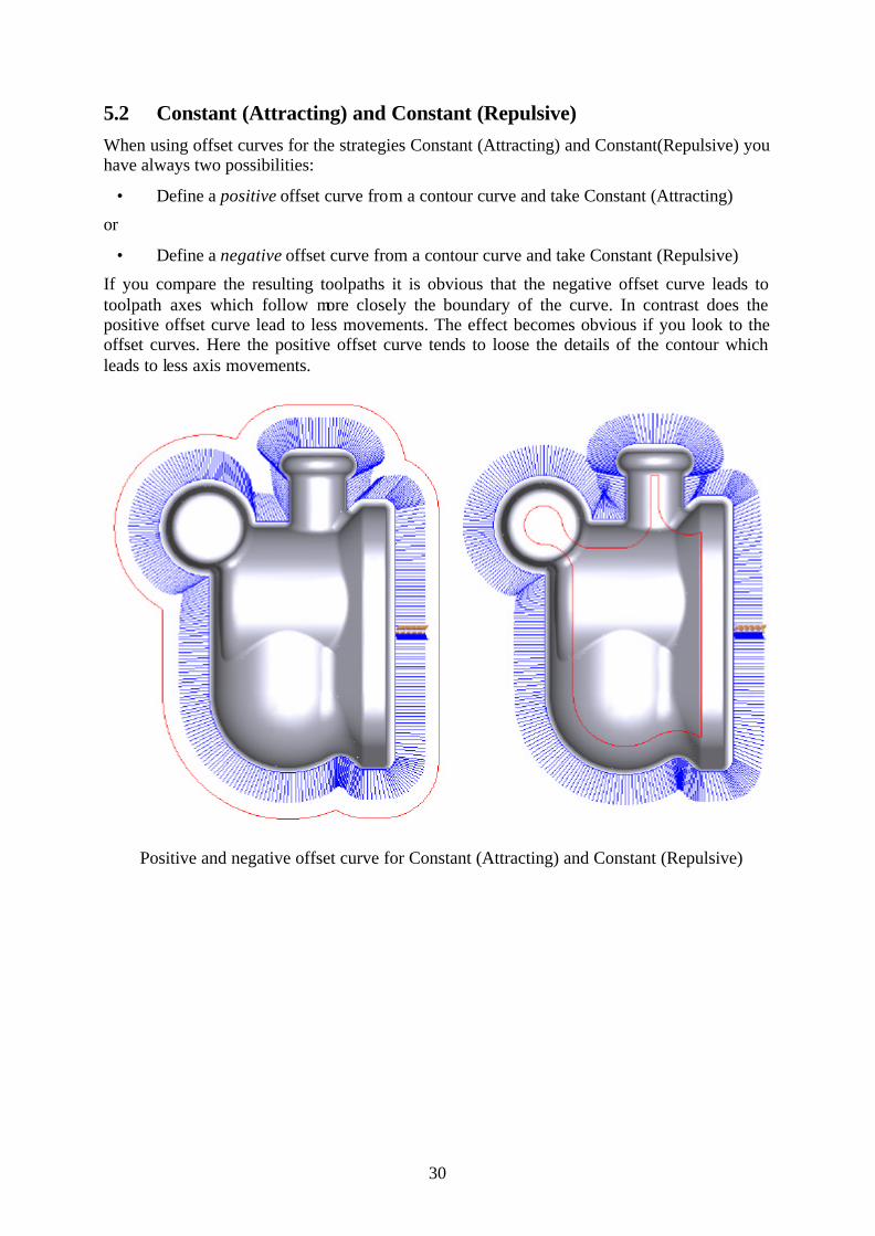
5.2 Constant (Attracting) and Constant (Repulsive) When using offset curves for the strategies Constant (Attracting) and Constant(Repulsive) you have always two possibilities:
• Define a positive offset curve from a contour curve and take Constant (Attracting)
or
• Define a negative offset curve from a contour curve and take Constant (Repulsive)
If you compare the resulting toolpaths it is obvious that the negative offset curve leads to toolpath axes which follow more closely the boundary of the curve. In contrast does the positive offset curve lead to less movements. The effect becomes obvious if you look to the offset curves. Here the positive offset curve tends to loose the details of the contour which leads to less axis movements.
Positive and negative offset curve for Constant (Attracting) and Constant (Repulsive)
31
6 Known Problems and Limitations • Copying of toolpaths should be avoided if the insert position is not the last toolpath
and the 3- to 5-axis interface is running. Otherwise an automatic renumbering will be done and the interface will not be informed and save to the old toolpath numbers.
• Both 3to5axis and 5tomachine do only consider the geometry plus stock allowance for collision avoidance. An arbitrary stock model can not be used. Hence, only finishing toolpaths can be supported by these modules. Roughing toolpaths are definitely not supported.
• The module 3to5axis does only support ball cutters. • The module 5tomachine does currently not consider collisions with the machine
kinematics. Currently only the angle limitations of the machine are considered.
Sescoi R&D, www.sescoi.com


