3rgonne Bational Xaboratorg
49
ANL-6554 ANL-6554 3rgonne Bational Xaboratorg INSTRUMENTED TEMPERATURE-CONTROLLED CAPSULES FOR IRRADIATIONS IN THE CP-5 REACTOR by W. N. Beck and R. J. FouseIc
Transcript of 3rgonne Bational Xaboratorg
ANL-6554 ANL-6554
3rgonne Bational Xaboratorg INSTRUMENTED TEMPERATURE-CONTROLLED
CAPSULES FOR IRRADIATIONS
IN THE CP-5 REACTOR
by
W. N. Beck and R. J. FouseIc

LEGAL NOTICE
This report was prepared as an account of Government sponsored work. Neither the United States, nor the Commission, nor any person acting on behalf of the Commission:
A. Makes any warranty or representation, expressed or implied, with respect to the accuracy, completeness, or usefulness of the information contained in this report, or that the use of any information, apparatus, method, or process disclosed in this report may not infringe privately owned rights; or
B. Assumes any liabilities with respect to the use of, or for damages resulting from the use of any information, apparatus, method, or process disclosed in this report.
As used in the above, "person acting on behalf of the Commission" includes any employee or contractor of the Commission, or employee of such contractor, to the extent that such employee or contractor of the Commission, or employee of such contractor prepares, disseminates, or provides access to, any information pursuant to his employment or contract with the Commission, or his employment with such contractor.

ANL-b554 Engineering and Equipment (TID-4500, 18th Ed.) AEC Research and Development Report
ARGONNE NATIONAL LABORATORY 9700 South Cass Avenue
Argonne. Illinois
INSTRUMENTED TEMPERATURE-CONTROLLED CAPSULES FOR IRRADIATIONS IN THE CP-5 REACTOR
by
W. N. Beck and R. J. Fousek
Metallurgy Division
Program 6.1. 33
Portions of the material in this report appeared in the following Metallurgy Division Progress Reports:
Report No. Pages "a te
ANL-6330 i n December 1960
October 196Z
Operated by The University of Chicago under
Contract W - 3 I -1 09-eng-38 with the
U. S. Atomic Energy Commission


TABLE OF CONTENTS
P a g e
ABSTRACT ' '
INTRODUCTION *
DESCRIPTION OF THE C P - 5 RESEARCH REACTOR 5
CAPSULE ASSEMBLY ^
DEISCRIPTION OF CAPSULE 9
TEMPERATURE INSTRUMENTATION '^
PREIRRADIATION INSPECTION AND TESTS OF C A P S U L E AND C O M P O N E N T S ' "̂
POST IRRADIATION HANDLING OF T H E E X P E R I M E N T 19
PERFORMANCE CHARACTERISTICS OF THE CAPSULES ZO
ACKNOWLEDGMENTS ^^
REFERENCES ^^


LIST OF FIGURES
No. Title Page
1. Elevation of the CP-5 Research Reactor 6
Z. CP-5 Cylindrical Fuel Element before Modification ^
3. Irradiation Capsule Attached to Center Shield Plug 8
4. Disassembled View of Capsule Components 10
5. Fin Area Contacts Tested in Double-wall Capsules H
6. Two-tier Disk-type Specimen Holder with Jacketed Fuel Specimens ' "
7. Temperature Distribution through Fuel Element Irradiation Capsule ^•'
8. Top Cap of Capsule Showing Thermocouples and Heaters Brazed to Zircaloy with ANL-11 Alloy 15
9. Controllers and Recorders Installed in the Basement of the CP-5 Reactor for Operation of Irradiation Experiments in Five Vertical Thimbles ' '
10. Measured Central Irradiation Temperatures in 0.144-in.-Diameter. 10% Enriched U-5 w/o Fs Alloy Specimens versus Reactor Power for Various Fin Contact Areas 21
11. Irradiation Temperatures versus Reactor Power for Three Fuel Materials Tested ^2


INSTRUMENTED TEMPERATURE-CONTROLLED CAPSULES FOR IRRADIATIONS IN THE C P - 5 REACTOR
by
W. N. Beck and R. J. Fousek
ABSTRACT
Instrumented, temperature -control led irradiation c a p s u l e s are being operated in the vert ica l fuel tubes of the C P - 5 tes t reactor . The fuel tubes were modified inorder to divert reactor coolant into the tubes to cool the c a p s u l e s , and the shield plugs were rev i sed to accommodate the capsule a s s e m b l i e s . Fuel m a t e r i a l s and structural m a t e r i a l s have been s u c c e s s f u l l y irradiated for periods in e x c e s s of one y e a r . The report includes a descr ipt ion of the present c a p su le and a s s e m b l y , the method of temperature control and instrumentat ion, and performance c h a r a c t e r i s t i c s of the c a p s u l e s .
INTRODUCTION
The development of fuel mater ia l s for reac tors is general ly a c c o m panied by an evaluation program m which the exper imental fuel "Material is irradiated under various h .gh- temperature and burnup condit ions . These exper iments can be performed by uti l is ing suitable c a p s u l e s , contaimng representat ive configurations of the fuel, which are introduced into a reactor irradiat ion faci l i ty . Subsequent post irradiat .on examination and ™ " « / " - ^ -ments of the s p e c i m e n s s e r v e to es tabl i sh the operation behavior of the fuel under study.
In performing a meaningful irradiation experiment it is e s sen t ia l that the d e s i r e d fuel t emperature be maintained throughout the irradiation period For that reason the des ign of the capsule must be such that the Temperature can be continuously monitored, and means must be provided whereby the t emperature can be control led . From exper ience g - n e d by study of s e v e r a l hundred uninstrumented capsu les irradiated in the MTR and ETR r e a c t o r s . d ) a capsule configuration was adopted which was suitable for convers ion to a thermocouple - ins trumented , re s i s tance h e a t e r - c o n t r o l l e d exper iment .
C P - 5 a heavy water -coo l ed .ind m o d r r . i f d r.-s.-.irch reactor lo cated at the n i i n o i . s i te of Argonno N.ilion.il l...l>or..tory. w.is s e l ec ted as

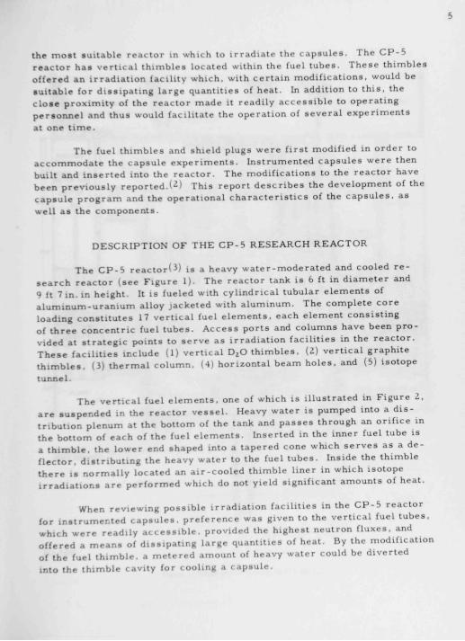
the most suitable reactor in which to irradiati- the c a p s u l e s . The C P - 5 reactor has ver t ica l th imbles located within the fuel tubes . These thimbles offered an irradiat ion facil i ty which, with certa in modif icat ions , would be suitable for d iss ipat ing large quantities of heat. In addition to th is , the c l o s e prox imity of the reactor made it readily a c c e s s i b l e to operating personnel and thus would faci l i tate the operation of s evera l exper iments at one t i m e .
The fuel th imbles and shield plugs were first modified in order to accommodate the capsule e x p e r i m e n t s . Instrumented capsu le s were then built and inserted into the reactor . The modif icat ions to the reactor have been prev ious ly reported .U) This report d e s c r i b e s the development of the capsule program and the operational c h a r a c t e r i s t i c s of the c a p s u l e s , as well as the components .
DESCRIPTION OF THE C P - 5 RESEARCH REACTOR
The C P - 5 reactor(^) i s a heavy water -moderated and cooled r e search reactor ( see Figure 1). The reactor tank is 6 ft in d iameter and 9 ft 7 in. in height. It is fueled with cyl indrical tubular e l ement s of a luminum-uranium alloy jacketed with aluminum. The complete core loading const i tutes 17 vert ica l fuel e l e m e n t s , each e lement cons is t ing of three concentr ic fuel tubes . A c c e s s ports and columns have been provided at s trateg ic points to s e r v e as irradiat ion fac i l i t i es in the reactor . These fac i l i t i e s include (1) ver t ica l DjO th imbles . (2) vert ica l graphite th imbles . (3) thermal column. (4) horizontal beam h o l e s , and (5) isotope tunnel.
The vert ica l fuel e l e m e n t s , one of which is i l lustrated in Figure 2. are suspended in the reactor v e s s e l . Heavy water is pumped into a d i s tribution plenum at the bottom of the tank and p a s s e s through an ori f ice in the bottom of each of the fuel e l e m e n t s . Inserted in the inner fuel tube is a thimble , the lower end shaped into a tapered cone which s e r v e s as a def lector, distributing the heavy water to the fuel tubes . Inside the thimble there is normal ly located an a i r - c o o l e d thimble liner in which isotope irradiat ions are performed which do not yield significant amounts of heat.
When reviewing poss ib le irradiat ion fac i l i t i es in the C P - 5 reactor for instrumented c a p s u l e s , pre ference was given to the vert ical fuel tubes , which were readily a c c e s s i b l e , provided the highest neutron f luxes , and offered a m e a n s of d iss ipat ing large quantities of heat. By the modif ication of the fuel thimble , a metered amount of heavy water could be diverted into the thimble cavity for cooling a capsu le .

a/TL»« or KJWCOMCRm
111-7838
PtPl TUNNEL -
Fijure 1. Elevjuoii u( CP-S Rcicjci h Ri .i> i-i


SHIELD
019 M .UMNUM-
- 052 2CX URANIUM-ALUMINUM ALLOY
•-OIS ALUMINUM DIFFERENTIAL TRANSFORMER
FUCL Tuae WALL
EMERGENCY COOLANT TUBE
SHIELDING PLUG
FLOAT - n DAMPING CUP a FLOAT SUPPORT
LIQUID LEVEL
^ IN TANK
THERMOCOUPLE
- THIMBLE AND
n LINER
FUEL TUBES
THIM8LC UNER
SECTION » - »
SEAL SURFACES
COOLANT INLET
ORIFICE AND BALL CHECK
PLENUM
i*4-n
Flginc a. CP-6 CyllnJl lcAl f in-l Element hcl..tr M..J1IK Alioil


Six ver t i ca l fuel th imbles were al located for the exper iments and the n e c e s s a r y hardware rev i s ions were made. These included modif ications to the outer shield p lugs , center shie ld, and thimbles . (2) The introduction of heavy water into the thimble cavity was a significant departure from the prev ious ly es tabl i shed functions of the thimble and, although flow rates could be ca lculated , an exper imenta l verif icat ion was made in a fu l l - s ca l e mockup of a fuel tube a s s e m b l y .
The p r e s e n c e of the heavy water in the thimble cavity during i r radiation presented the poss ibi l i ty of trapping explos ive mixtures of D^ and O, at the top of the thimble . To avoid this hazard a helium purge s y s t e m was incorporated which uti l ized the reactor re servo ir supply of hel ium, pumping It to the thimble cavity and exhausting it to the hel ium atmosphere of the reactor v e s s e l . A paral le l coupled two-pump sys tem is ut i l ized. One pump is in continuous operation while the other operates only if the p r e s sure in l ines d e c r e a s e s by 50 per cent.
CAPSULE ASSEMBLY
The complete capsule a s s e m b l y is approximately 9 ft long and is divided into three sec t ions : center shield plug, extension tube, and capsule ( see Figure 3).
unM.m Mi
1 1 Z B ^3''CMP^Sbcfii?QS©2<l - - + • -
FIgive 3. Inuliitlon C»piule Atuched lo Ctnui Shield Plug
The center shield plug is a s ta in l e s s s tee l casing filled with lead shot and paraffin. Additional thermal neutron shielding is provided by two Boral d i sks embedded in the bottom of the cas ing . A spiral , y - m . - I D tube i s contained in the plug through which the capsule wiring harnes s i s threaded. The top flange of the plug s ea t s on the outer shield plug in the reactor and s e a l s with a neoprene "O" ring. E lec tr ica l connections are made at the top of the plug through a sea led , multiple pin receptac le .
The extens ion tube flange is bolted to the bottom of shield plug. This -^-in -OD, ZS aluminum flange is joined to the extension tube proper ( ' - i n * - OD aluminum) with a Type 304 s t a i n l e s s s tee l .Swagelock reduction fitting Between the flange and the shield plug, a i - i n . - t h i c k cadmium plate has been incorporated as a thermal neutron shield to prevent the


bottom of the shie ld plug from becoming highly radioact ive after prolonged and repeated e x p o s u r e s to the reactor flux. The extens ion tube houses the wiring originat ing from the capsu le , and the length of tube is varied to pos i t ion the capsule within a des i red flux region in the reactor fuel tube. An eye c l ip is fastened to the tube \Z in. above the top of the capsu le . When the exper iment is removed from the reactor , a cable is attached to the c l ip and the extens ion tube is s e v e r e d . The capsule may then be eas i ly t rans ferred to a shie lded container and then into a shielded ce l l . The ex tens ion tube IS connected to the capsule by a second Swagelock which n e c e s s a r i l y must be water- t ight , as it is located below the DjO level in the reactor v e s s e l .
DESCRIPTION OF CAPSULE
The capsule i s a cy l inder , 1 - j in. in d iameter , which may vary in length from 1 3 to 29 in. depending upon the s i z e and placement of the irradiat ion s p e c i m e n s . It is divided into two main compartments - the connector housing, and the s p e c i m e n container . An exploded view of a typical capsule i s shown in Figure 4. Spacer s tuds , ^ in. high, are welded to the outer surface of the capsule which center the tube within the reactor thimble and maintain the w a t e r - c o o l e d annulus. A c l earance of j j in. is maintained between the studs and the thimble wall to faci l i tate insert ion of the capsule in the th imble .
The connector housing is a sea led enc losure above the spec imen conta iner , where e l e c t r i c a l connect ions to the hea ters are made and where the sheathed thermocoup le s are joined to f lexible leads m individual potted adaptors . The chamber is fabricated of mater ia l s i m i l a r to that used for the capsule body and is joined to the capsule by a s e a m weld. The ambient t emperature within this housing during irradiat ion has been measured to be 30 to 35 per cent of the mean temperature r i se of the sodium or NaK surrounding the s p e c i m e n s . All insulation mater ia l used within the chamber is inorganic and capable of withstanding prolonged irradiat ion at t e m p e r a t u r e s up to 500"C.
The s p e c i m e n container encapsu la tes the exper imenta l s p e c i m e n s , thermocouple junct ions , auxi l iary e l e c t r i c a l heater , and a heat transfer medium which is general ly NaK. The cyl inder wall may be so l id one-p iece construct ion , duplex tubing in tight contact , or two tubes separated by c i rcumferent ia l f ins . The se l ec t ion of the part icular configuration of capsule body is dependent upon the des i red irradiat ion temperature of the s p e c i m e n s . Duplex tubing is preferred over a s ingle wall for safety reasons , for fai lure of one of the tubes will not open the capsule contents to the re ac tor coolant. The duplex tubing that has been used is not metaUurgica l ly bonded but c o n s i s t s of two tubes in intimate contact . This contact i s at tained by drawing the tubes together to 0.015 in. u n d e r s i z e . The tubes are


10
ConntcfOf Cnamb«r
•_•
Sp«C<fft«'>t Ond
S p ^ C W f Mold* '
TonlOlum
• Chamber
EliCtric HtOl«rt
^
£1-433 1 / J X
Finufc 4. iJiiaiiciTihIcO V iew tif T y p u J l
Capi i i l r <;i>inpi>iiciiU


n
then s i zed by expanding with no restraint on the outs ids d iameter to the spec i f ied l . 5 - i n . OD. The a s s e m b l e d tube is s t r e s s re l i eved and annealed at 050°C. The drawing operation is performed without the use of lubricant between the w a l l s .
Heat transfer b a r r i e r s in the form of fins have a l so been used. T h e s e are used pr imar i ly when irradiating structural mater ia l s or fuel s p e c i m e n s producing compar i t ive ly low amounts of heat. D iagrams of the var ious fin spac ings that have been used are shown in Figure 5. The fins are cut into the outside d iameter of the inside tube. A drawing operation is applied to a s s u r e that the fins make intimate contact with the inside d iameter of the outside tube. Measurements of temperature scal loping along the length of the tubes showed that, at an average dis tance of 0.03 in. away from the inside capsule wal l , the variation was l e s s than 2 percent .
FIN ARC* CONTACT r >N AREA CONTACT SOU
. O l O
•I •' • • } >.
-H ^
-• •• a<^» —»U» IN ARtA CONTACT
I 0 «
mil' I'lf̂ i iVfl 'II ll ^
N ARC* CONTACT 9 \
Figure S
Fin ArcA ContAcu Tci led in Double-wi l l CApiulcl. The Annulus between Finj b Filled wuh HelluiTi.
-±: r s ABC* CONTACT
- 0 *
The m a t e r i a l s used for capsu le s have been Type 304 s ta in l e s s s tee l and Z i r c a l o y - 2 . The majority of irradiat ions performed have been with Z i r c a l o y - 2 c a p s u l e s . The preference for Z irca loy -2 was due pr imari ly to the low thermal neutron-absorpt ion c r o s s sec t ion of the mater ia l and better compatibi l i ty with the metal l ic fuels undergoing irradiat ion.
One fuel, however , which revealed a tendency to attack Z irca loy -2 is uran ium-20 w / o plutonium-10 w / o f i s s ium al loy. In capsu les containing this fuel mater ia l a 0.01 0- in . - th ick tantalum cup has been incorpor.ited inside the heater windings, which insert ion i so la tes the s p e c i m e n holdi-r from the capsule body. All capsule parts .irr joinr<l by i n e r t - g a s - s h i e l d e d tungsten e lec trode welding. No fi l ler metal is .i<ldocl.

12
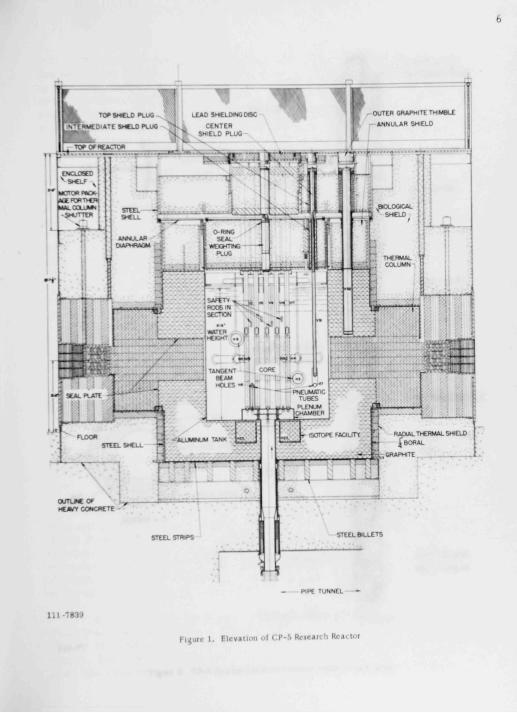
T h e s p e c i m e n s in the c a p s u l e a r e m o u n t e d in h o l d e r s w h i c h l i m i t e x c e s s i v e v e r t i c a l and l a t e r a l m o t i o n , y e t p r o v i d e a m a r g i n of c l e a r a n c e f o r p o s s i b l e s w e l l i n g of t h e f u e l . T h e m a j o r i t y of i r r a d i a t i o n s h a v e b e e n c o n d u c t e d o n c y l i n d r i c a l l y s h a p e d s p e c i m e n s ; h o w e v e r , the c a p s u l e w i l l a l s o s e r v e to i r r a d i a t e m a t e r i a l s of a v a r i e t y of d i f f e r e n t s h a p e s . T h e s p e c i m e n s a r e l o c a t e d t h r e e to a t i e r s o that t h r e e s p e c i m e n s a r e at the s a m e v e r t i c a l e l e v a t i o n w i t h i n t h e c a p s u l e . T h i s a r r a n g e m e n t h a s p r o v e n v a l u a b l e in c o m
p a r i n g the i r r a d i a t i o n c h a r a c t e r i s t i c s of d i f f e r e n t m a t e r i a l s u n d e r e s s e n t i a l l y i d e n t i c a l i r r a d i a t i o n c o n d i t i o n s , for the t e m p e r a t u r e s and n e u t r o n f lux at the s a m e e l e v a t i o n a r e r e l a t i v e l y u n i f o r m .
F i g u r e 6 s h o w s a t y p i c a l s p e c i m e n h o l d e r a s s e m b l e d w i t h t w o t i e r s of s p e c i m e n s . T h e h o l d e r c o n s i s t s of an a s s e m b l y of s t a c k e d d i s k s w h i c h s u p p o r t and p o s i t i o n the s p e c i m e n s , 120 a p a r t , in h o l e s d r i l l e d t h r o u g h t h e d i s k s . A d d i t i o n a l h o l e s in the d i s k s s e r v e to p o s i t i o n a c c u r a t e l y the t e m p e r a t u r e -m e a s u r i n g t h e r m o c o u p l e s and m o n i t o r w i r e s f o r f lux m e a s u r e m e n t . T h e m o n i t o r w i r e s a r e s t r u n g l o n g i t u d i n a l l y b e t w e e n s p e c i m e n s , on the s a m e r a d i u s p a s s i n g t h r o u g h the c e n t e r of the s p e c i m e n s . T h e h o l d e r s a r e f a b r i c a t e d of 0 . 0 2 5 - i n . - t h i c k Z i r c a l o y - 2 . T h e s p a c e r s of t h e d i s k h o l d e r w h i c h n o r m a l l y do not c o m e in c o n t a c t w i t h the fue l a r e T y p e 304 s t a i n l e s s s t e e l .
Specinien
Ttieimocouple
EI-123 1/2X
Flgisc 6. Two-net Duk-iype Specimen Holdet with jAcketed Fuel Spcclment
T h e t y p e of m a t e r i a l s w h i c h h a v e b e e n i r r a d i a t e d i n c l u d e both s t r u c t u r a l and fue l m a t e r i a l s . T h e fue l s p e c i m e n s a r e c y l i n d e r s a p p r o x i m a t e l y 0 . 1 4 4 i n . in d i a m e t e r and o n e to t w o i n c h e s l o n g . T h e y h a v e b e e n b o t h c l a d and u n c l a d . In s o m e i n s t a n c e s w i t h c l a d u r a n i u m fue l the c l a d d i n g w a s o p e n at the t o p . P l u t o n i u m fue l s p e c i m e n s h a v e a l w a y s b e e n c o m p l e t e l y c l a d . In m a n y of t h e u r a n i u m s p e c i m e n s an a x i a l h o l e w a s d r i l l e d ha l f the l e n g t h of the f u e l , and a t h e r m o c o u p l e w a s i n s e r t e d f o r d i r e c t m e a s u r e m e n t of c e n t r a l furl I r m p c r.ilu r r s .

13
Auxil iary t emperature control is provided in the c a p s u l e s by e l e c t r i ca l r e s i s t a n c e h e a t e r s . The e l e m e n t s are s t a i n l e s s s t e e l - s h e a t h e d N i c h r o m e - V or Kanthal wire insulated with magnes ium oxide . The e lement i s wrapped into a coi l which e n c i r c l e s the s p e c i m e n h o l d e r s . At the topm o s t convolution of the heater , the Nichrome or Kanthal is joined to a n ickel conductor . This procedure is used to maintain the heat -generat ing portion of e l ement below the NaK level in the capsu le . By so doing, it is p o s s i b l e to operate the e l ement at higher surface heat f luxes than the normal in -a ir rating. Another cons iderat ion was to a l l ev iate the n e c e s s i t y of d iss ipat ing additional heat in the connector chamber . The first heaters were -i in. in d i a m e t e r . The life expectancy of these units was unpredictable and usually quite short . The predominant failure a r o s e from arcing from the nickel conductor to the sheath at the point where the bare wire emerged from the sheath. Contamination of the magnes ium oxide was suspected , and att empts to re inforce the e l e c t r i c a l r e s i s t a n c e wire at this point were made without substantial ly prolonging the operational l i fe . The d iameter of the heater was then i n c r e a s e d to ^ in. , and the fai lure rate d e c r e a s e d by 60 per cent^ Sealing the exposed m a g n e s i u m oxide with a porce la in g laze and storing the units in a m o i s t u r e - f r e e environment was found to extend the shelf life of the h e a t e r s . The e l e m e n t s are rated for 1000 w at 110 v. S imi lar units with 3000-w rating have a l so been used. Two paral le l -wound lOOO-w heaters have proven ef fect ive in control l ing the capsule t emperature , with the additional safeguard that, in the event of failure of one heater , the other can maintain the irradiat ion t emperature . The spacing of the convolutions of the h e a t e r s must be taken into cons iderat ion in determining the temperature profi le of the capsu le a s wel l as the auxi l iary heat-f lux densi ty . This spacing may be used to advantage in that the convolutions may be adjusted prior to capsule a s s e m b l y as a minor correc t ion to the temperature profi le .
Flux moni tors m the capsu le s are used to obtain pre l iminary integrated flux va lues for calculat ing fuel burnup. The a l loys from which monitor w i r e s have been fabricated are a luminum-cobal t , manganese -coba l t , and n i cke l - coba l t . D i a m e t e r s of the w i r e s have varied from 0.010 in. to 0 035 in. , and the cobalt content was varied from 0.066 to 0.7 per cent. The cobalt concentrat ion is p r e s e l e c t e d on the bas i s of an anticipated radiation intensi ty of -^ -."• s e g m e n t s of the wire . The a luminum-cobal t w ires are used in c a p s u l e s in which the central fuel t e m p e r a t u r e s wil l not exceed bSCC The n icke l -coba l t w ires have been used in capsu le s m which central t e m p e r a t u r e s have been as high as 1000°C. The manganese -coba l t w ires in NaKor sodium tend to u n d e r g o a d i s s o l u t i o n p r o c e s s in an ambient temperature above 500°C. and for that reason their application has been l imited to low-temperature i rrad ia t ions .
TEMPERATURE INSTRUMENTATION
The temperature m e a s u r e m e n t s within Ihr i .ipHuU- li.iv.- hrrn monitored e x c l u s i v e l y by t h e r m o c o u p l e s . The pos i t ions or .ire.i.t where


14
t e m p e r a t u r e m e a s u r e m e n t s have been taken are : (1) within the connector c h a m b e r , (2) sodium or NaK in the capsu le , and (3) center regions of the fuel s p e c i m e n s .
The temperature of the connector chamber was m e a s u r e d in severa l c a p s u l e s in order to determine max imum operating conditions for insulating m a t e r i a l s and a d h e s i v e s .
Within the s p e c i m e n chamber , the sodium or NaK temperatures have been measured at the following pos i t ions: adjacent to the spec imen on the center l ine of the fueled portion, along the length of the spec imen in order to de termine the vert ica l t emperature prof i le , between two s p e c i m e n s , and predetermined d i s tances from the s p e c i m e n s to the capsule wall . The majority of m e a s u r e m e n t s which s e r v e to es tab l i sh central s p e c i m e n t e m perature are taken from thermocouples located adjacent to the spec imens on a radial line between the center of the capsule and the center of the s p e c i m e n . This location is preferred because the profile of the temperature distribution in the capsule is such that the thermocouple may be misplaced as much as 0.1 in. with a resultant maximum e r r o r of only 3 per cent in determining the central fuel t emperature .
( •WOCtXiALC
0 | 0 COOLANT
FllKC •'• TempttAtute Diil/lbulum thtough Fuel Element btAdiAtion CAfSule. Only One uf the Thiei Speclineni in the Tirt b Sln.wn.
The temperature distr ibution within the capsu les is de ter mined by calculat ion, e l ec tr i ca l analogue,(•*) and direct t h e r m o couple readings . A profile of t e m perature distribution within a typical capsule is shown in Figure 7. Spec imens have been used with axial 0 .043- in . holes dril led half the length of the spec imen . A 0 .040 - in . -d iameter sheathed thermocouple was inserted in this hole , and a verif icat ion of the analogue data was made.
Thermocouples used in the exper iments are a j^ - in . -d iameter sheathed i m m e r s i o n type with c h r o m e l - a l u m e l cal ibration and a potted transit ion to the lead w i r e s . The operating temperature range in the capsu le s is normal ly below 1000°C. and for that reason the c h r o m e l - a l u m e l wire has proven sat i s factory . In .iddition. this


15
couple has not demonstrated a tendency toward irradiation-induced emfs and has retained its calibration after being in continuous service for over a year. The sheathing material specified is usually Type 304 stainless steel. Tantalum-sheathed thermocouples. 0.040 in. in diameter, have also been used for central fuel instrumentation. Quality control of the tantalum sheath mater ia l was a problem as was also obtaining a satisfactory braze between tantalum and the Zircaloy-2 capsule cap. The present approach is to utilize Type 304 stainless steel-sheathed thermocouples which are plated with 0.002 in. of tantalum metal. This plating covers the sheath from the hot junction of the thermocouple to a position just above the NaK level in the capsule.
Potted transi t ions, which are located in the connector chamber. alleviate the necessity of threading semirigid sheathed conductors through the extension tube and shield plug. Twenty-four-gauge solid lead wires, insulated with a double covering of Fiberglas, are welded to the sheathed
thermocouple wires . Potting compounds found to be satisfactory for this application are Sauereisen No. 29 or No. 31.
The thermocouples are introduced into the specimen chamber through holes drilled in the top cap. Brazing of thermocouples and heater leads is performed in one operation with an induction welder and in a controlled atmosphere. A photograph of a typical cap after brazing is shown in Figure 8. ANL-11 alloy*^' is used to braze the stainless steel-sheathed thermocouples in the Zircaloy-2 caps. This alloy has the composition zirconium-8 w/o nickel-8 w/o chromium and has a melting point near 900°C. It IS compatible with sodium and NaK. and is corrosion resistant to water.
In brazing 0.040-in.-diameter thermocouples to the cap, quite frequently the sheath would be perforated. To avoid this defect, protective sleeves, having a wall thickness of 0.020 in., were swaged over the thermocouple at the region where the braze had to be made. The sleeve was initially brazed to the thermocouple and tested before it was brazed to the cap. An improvement to this procedure was the development and adoption of a standard j ^ -in.-OD thermocouple with the last inch or inch
ioe-4«6b
Figure 8
Top CAP ol CAp»ule Showing Thetmo-
couplM And HcAten BtAzcd to ZlrcAloy
wilh ANL-11 Alloy.

16
and a half swaged to a d iameter of 0.040 in. This permitted a cap braze to a 5̂ - i n . - d i a m e t e r sheath of sufficient t h i c k n e s s , yet provided a means of m e a s u r i n g center fuel t e m p e r a t u r e s . The f irst units tes ted in capsu les w e r e fabricated at Argonne f a c i l i t i e s . C o m m e r c i a l s o u r c e s are presently avai lable for this type of thermocouple .
The thermocouple life expectancy in this application is l imited by the thermal shock r e s i s t a n c e of the individual thermocouple . Ninety - s ix per cent of all fa i lures have been attributed to thermal shock. Whenever the C P - 5 reactor " s c r a m s . " the capsule t e m p e r a t u r e s drop to the reactor coolant t emperature within a period of 2 to 3 s ec provided e l e c t r i c a l heating is not being used . During s o m e irradiat ions , over 500 thermal shocks have been recorded. Bench t e s t s , s imulat ing thermal shock conditions in the reac tor , have been conducted on thermocouples of s ix major manufacturing c o n c e r n s . The overa l l average number of thermal shocks that the thermocouples could withstand was 156. The lowest value was one and the highest 630. The fai lure within units fabricated with a hot junction grounded to the sheath IS genera l ly a separat ion of one of the w i r e s from the junction. On units having ungrounded hot junct ions , the wire may separate at the junction or anywhere along the length which has been heated. Increasing the diameter of the thermocouple or the s i z e of the wire has not improved the thermal shock r e s i s t a n c e .
Organic thermocouple insulat ions have been evaluated inside of connector c h a m b e r s at t e m p e r a t u r e s of 175''C and thermal neutron fluxes of 5 X 1 0 " n / s e c . The effect of these condit ions on a nylon cover ing was a comple te separat ion from the thermocouple w i r e s . Fused Teflon embritt led and flaked off the w i r e s . Polyvinyl Nylon became very britt le and cracked but adhered to the w i r e . Inorganics , such as F iberg las over F iberg las and F i b e r g l a s over a s b e s t o s , suffer d i sco lorat ion and become britt le but do not lose their e l e c t r i c a l r e s i s t i v i ty to a point where it affects the thermocouple ca l ibrat ion.
The extens ion leads of the thermocouples as well as the heater wires are grouped in the connector chamber and fed through the extension tube and the shie ld plug. The ends are so ldered to a multipin sea led receptac le . Compensating c h r o m e l and a lumel mater ia l i s used in the a s s e m b l y of matched pa irs of pins . The msulatmg mater ia l of the receptac le is s i l i cone rubber. The bottom surface of the insulating mater ia l is continuously exposed to the reactor environment , the major const i tuent being he l ium. Prolonged ex posure to the reactor environment tends to embri t t l e and crack the s i l icone rubber. The rate of deter iorat ion has been noted to be approximately O.OIO in. per month; however , over a period of 14 months the receptacle remained p r e s s u r e - t i g h t .
Extension c a b l e s , 60 ft in length, connect the shield plug to the t e m perature instrumentat ion located in the basement of the reactor building.

17
The matched pairs of thermocouple compensat ing l ines are 14-gauge wire c o v e r e d with 0.040 in. of polyvinyl insulat ion. The shielded cables t e r minate at one end in a matching s c r e w thread receptac le , which mates the connector on the shield plug, and at the other end to a terminal board in the instrument cabinet . Four copper conductors are included for the capsule h e a t e r s . The bundle of w i r e s is encased in a shielded braid as a protect ion against abras ion .
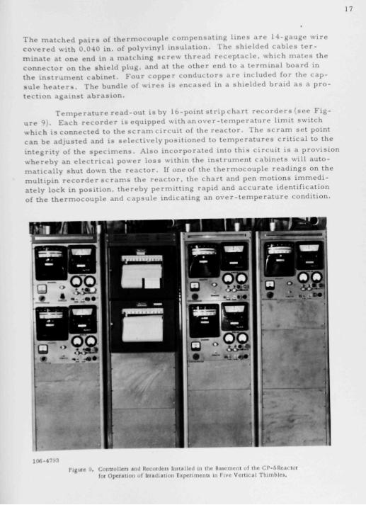
Temperature read-out is by 1 b-point strip chart recorders (see Figure 9) . Each recorder is equipped with a n o v e r - t e m p e r a t u r e limit switch which is connected to the s c r a m c ircui t of the reactor . The s c r a m set point can be adjusted and is s e l e c t i v e l y posit ioned to t emperatures cr i t i ca l to the integrity of the s p e c i m e n s . Also incorporated into this c ircuit i s a provis ion whereby an e l e c t r i c a l power lo s s within the instrument cabinets will automat ica l ly shut down the reactor . If one of the thermocouple readings on the multipin recorder s c r a m s the reactor , the chart and pen motions immedi ately lock in pos i t ion, thereby permitt ing rapid and accurate identification of the thermocouple and capsule indicating an o v e r - t e m p e r a t u r e condition.
prw/it^
r^9S
1 0 6 - 4 " '•••
Figure J. C o n a i i l l e t l And Rccmdcl l I n i l a l i r d in Ilic l lA i rn i rn I ot tlir C I ' - .SRcn M I for OperAtlon of IrtAdlAlion E i p c n i n c i i u tn I ivr V c r i u a l T l i i m h l n .


18
Each capsule is provided with a minimum of six thermocouples. Fai lure of these thermocouples has not been deemed as a condition necessar i ly requiring shutting down the reactor or removing the capsule. For that reason, the thermocouple-break provision within the recorders has been eliminated, so that a thermocouple failure will not cause the pen to t ravel upscale and tr ip the scram circuit .
One of the thermocouples in each capsule is connected to a separate mill ivoltmeter high-limit controller. This instrument is utilized as a tempera ture warning device and is preset to actuate at a temperature slightly higher than the control irradiation temperature . When this cont rol ler IS tripped, a warning light will be displayed on the control panel of the capsule experiment as well as on the panel in the reactor control room. If the thermocouple connected to the instrument fails, the warning light is actuated. A bypass relay circuit with a key lock switch permits clearing the warning light in the control room until the faulty thermocouple can be replaced.
The resis tance heaters in the capsules are operated with saturable core reactors controlled from a millivoltmeter-type controller. A rheostat was incorporated into the system to preset selectively a maximum wattage input to the heaters . Shunt res is tances , in the form of pushbutton switches, are tied across the output legs of saturable core reactors to suppress line surges . This shunt is used to short out the resistance of the heater at the moment the power switch is turned on. The instantaneous line surge can at t imes be of sufficient magnitude to arc across the heater in the capsule. Once the main power switch is on, the arc-suppress ion switch IS released.
The effective range of temperature control of the capsules with resis tance heaters is dependent upon the ratio of the available auxiliary heat to the heat developed in the specimens by fission. As this ratio dec reases , the desired irradiation temperature of the specimens must be approximated by capsule design independent of the use of the heater . The auxiliary heat then serves to compensate only for minor flux variations within the reactor core .
With the saturable core reactors it has been possible to maintain a desired central irradiation temperature of l2.5°C over extended periods
I t ime. It has not been possible to introduce sufficient auxiliary heat to maintain temperature during the reactor shutdowns with the specimen loadings that contain sizable quantities of fissile m.iterial.
o


19
PREIRRADIATION INSPECTION AND TESTS OF CAPSULE AND COMPONENTS
Special cons iderat ion had to be given to safeguard against the poss ib i l i ty of capsu le fai lure while in the irradiat ion faci l i ty . A s e r i e s of t e s t s w e r e e s tab l i shed which were des igned to s imulate the capsule behavior in the reactor . Mater ia l - inspec t ion procedures were adopted to e l iminate imperfect or quest ionable components . Double containment of the NaK was deemed n e c e s s a r y as wel l as providing a means of detect ing a fa i lure of one of the conta inments .
The stock mater ia l of which the capsu le s are fabricated is subjected to a careful v isual examinat ion for de fec t s . The mater ia l is then machined to s i z e and an eddy current , point probe technique is used to locate c r a c k s exceed ing 0.002 in. in depth. The capsule body, which const i tutes two separate tubes in intimate contact , is subjected to an X-ray inspect ion as wel l as an eddy current test of the inside and outside sur f a c e s . A grooved separat ion e x i s t s between mating sur faces of duplex tubing which, in event of fai lure of one of the tubes , permi t s the passage of NaK or DjO to a sea led chamber at the bottom of the capsule . The fai lure is detected by the loca l i zed change in temperature in the sealed chamber .
All welds are subjected to a he l ium leak check with a m a s s s p e c t r o m e t e r . The thermocouples are X-rayed , tested for leaks *ith a m a s s s p e c t r o m e t e r and cal ibrated before and after being welded into the top cap. The comple ted capsule a s s e m b l y , which includes the extens ion tube, IS p r e s s u r e checked at 90 ps i . This a s c e r t a i n s that the secondary container which is in d irec t contact with the reactor coolant is leak tight.
The proper p lacement of components within the capsule as wel l as the NaK leve l i s de termined by an X-ray inspect ion. The capsule i s then operated in a test stand at intended irradiat ion t e m p e r a t u r e s . While at this t e m p e r a t u r e , the capsule is vibrated for one hour to insure proper wetting of the NaK to all contacting s u r f a c e s . While the capsule is at the d e s i r e d operat ing temperature the thermocouples are a l so checked for ca l ibrat ion , and the NaK level i s again de termined by X-ray radiography.
The top shield plug is attached and the thermocouples are again checked with the auxi l iary heat s o u r c e in operat ion. This s a m e procedure IS repeated when the capsule is inser ted into the vert ica l thimble of the reac tor , before the reactor is brought to power.
POSTIRRADIATION HANDLING OF THE EXPERIMEN 1'
The irradiated c a p s u l e s are handled in .i cy l indru . i l transfer cask m e a s u r i n g 16 in. in d iameter and 5 ft in length. A l-ii i . .ixi.il hole extends


20
the full length of the cask, which is closed at both ends by shielded gates. The procedure in removing a capsule from a vertical thimble is to position the cask vertically over the thimble, and withdraw the 9-ft capsule assembly through the cask until the capsule containing the specimens is above the lower gate. This gate is then closed and a 20-ft steel cable is clipped to the recovery bracket on the extension tube. With the use of bolt cutters, the extension tube is severed immediately above the extension tube bracket. The capsule is then lowered by means of the attached cable to the bottom of the cask, and the top gate is closed. The cask is transferred to the face of a shielded cell, and the same cable serves to pull the capsule into the cell.
Prior to opening the capsule, a pinhole autoradiograph is taken.^ This serves to establish the location and condition of specimens. The amount of loose radioactive material at the bottom of the capsule can also be determined.
The capsules are opened with a vertical lathe. The top chamber is first separated, and the thermocouple leads as well as the heater junction are cut. The specimen chamber is then cut just below the top cap. The entire assembly, which includes heaters and specimen baskets, is then removed from the NaK. The NaK is dissolved off the assembly with butyl alcohol, and the specimens are removed for a postirradiation examination.
The capsules are opened in a hood within the hot cell in which is maintained a nitrogen atmosphere having an oxygen content of less than i per cent. This precaution precludes the possibility of excessive oxidation or fire which would damage the specimens.
PERFORMANCE CHARACTERISTICS OF THE CAPSULE
The capsule irradiations have been conducted in the thimbles in the center ring of reactor fuel elements. These vertical thimbles are designated as VT-4, -5. -8. -10. -13. and -14. The experiments have been performed under conditions of varying reactor power as the established operating level was raised in stages from 2 to 5 Mw. The neutron flux within the thimbles was found to be relatively linear with the increases in reactor power levels. Design of the various capsules was dependent upon the heat generation of the specimens, which for reactor powers near 2 Mw required the use of gas annuli to attain desired irradiation temperatures.
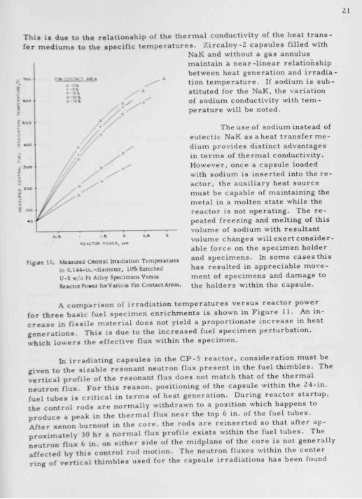
The types of gas annuli (that i s , the fin spacings) tested have been previously described. A graph comparing these annuli in terms of reactor power versus indicated central fuel specimen temperatures is shown in Figure 10. The curvature of the lines, which is accentuated as the fin contact area is decreased, follows the expected variations in heat transfer characteristics of this configuration, which is also discussed in roference 7.

21
This i s due to the re lat ionship of the thermal conductivity of the heat t r a n s fer m e d i u m s to the specif ic t e m p e r a t u r e s . Z ircaIoy-2 capsu le s filled with
NaK and without a gas annulus maintain a n e a r - l i n e a r relationship between heat generation and irradiation t emperature . If sodium is substituted for the NaK, the variation of sodium conductivity with t e m perature will be noted.
The use of sodium instead of eutect ic NaK as a heat transfer m e dium provides dist inct advantages in t e r m s of thermal conductivity. However, once a capsule loaded with sodium is inserted into the re actor , the auxil iary heat source must be capable of maintaining the metal in a molten state while the reactor is not operating. The re peated freezing and melting of this volume of sodium with resultant volume changes will exert cons iderable force on the spec imen holder and s p e c i m e n s . In some c a s e s this has resulted in appreciable m o v e ment of s p e c i m e n s and damage to the holders within the capsule .
• tACTon OC<*TA. >
Flgise 10. Mesiured Ceanal InidiAiion Temperatures in 0.144-in.-diAmeter, lOH Enriched U-5 w/o F« Alloy Specimen! Venm Reactor Power fofVATioui Fin ConiAct AreAj.
A c o m p a r i s o n of i r r a d i a t i o n t e m p e r a t u r e s v e r s u s r e a c t o r p o w e r f o r t h r e e b a s i c fue l s p e c i m e n e n r i c h m e n t s i s s h o w n in F i g u r e 1 1 . An i n c r e a s e in f i s s i l e m a t e r i a l d o e s not y i e l d a p r o p o r t i o n a t e i n c r e a s e in h e a t g e n e r a t i o n s . T h i s i s d u e to the i n c r e a s e d f u e l s p e c i m e n p e r t u r b a t i o n , w h i c h l o w e r s t h e e f f e c t i v e f lux w i t h i n the s p e c i m e n .
In i r r a d i a t i n g c a p s u l e s in the C P - 5 r e a c t o r , c o n s i d e r a t i o n m u s t be g i v e n t o t h e s i z a b l e r e s o n a n t n e u t r o n f lux p r e s e n t in t h e f u e l t h i m b l e s . T h e v e r t i c a l p r o f i l e of the r e s o n a n t f lux d o e s not m a t c h that of t h e t h e r m a l n e u t r o n f l u x . F o r t h i s r e a s o n , p o s i t i o n i n g of the c a p s u l e w i t h i n the 2 4 - i n . f u e l t u b e s i s c r i t i c a l in t e r m s of h e a t g e n e r a t i o n . D u r i n g r e a c t o r s t a r t u p , t h e c o n t r o l r o d s a r e n o r m a l l y w i t h d r a w n to a p o s i t i o n w h i c h h a p p e n s to p r o d u c e a p e a k in the t h e r m a l f lux n e a r the t o p 6 i n . of the f u e l t u b e s . A f t e r x e n o n b u r n o u t in the c o r e , the r o d s a r e r e i n s e r t e d s o that a f t e r a p p r o x i m a t e l y 30 h r a n o r m a l f lux p r o f i l e e x i s t s w i t h i n the fue l t u b e s . T h e n e u t r o n f lux 6 i n . on e i t h e r s i d e of the m i d p l a n e of t h e c o r e i s not g e n e r a l l y a f f e c t e d b y t h i s c o n t r o l rod m o t i o n . T h e n e u t r o n f l u x e s w i t h i n the c e n t e r r i n g of v e r t i c a l t h i m b l e s u s e d f o r the c a p s u l e i r r a d i a t i o n s h a s b e e n found


22
to be large ly free from fluctuations because of the .Klilitiun of absorbers in the outer r ings and reflector zones .
Figure U InAdiallon TcmperAturci Vtnm IVaclol Power for Three Fuel Malcruli TeiteJ. The Capsule Veuel Was Made uf Duplex Tubing Having 100 per cent Melal-to-Metal Contacu
Of a total oi ovi-r twenty capsu les irradiated in the C P - 5 fuel th imbles to date, there has been no incident of r e l e a s e of f i ss ion products or contamination of the reactor coolant. Some of the capsu le s have been in the ver t ica l th imbles for per iods exceeding one year .
The capsu le s have been relat ively s imple to install and remove . This operat ion does not require more than 15 min and is accompl i shed with min imum hazard to operating personnel . Observat ions on the operating
h a r a c t e r i s t i c s of the s y s t e m have demonstrated that it can be operated ttended for extended periods of t ime . Other than periodic routine checks
on the equipment, the only attention required is the placement of chart ro l l s , which IS done once a month.
c una
ACKNOWLEDGMENTS
The authors wish to recognize the . i s s i s tance of C P - 5 Reactor Operations personnel , without whose effort and interest the exper iments could not have been conducted. They arc a lso indc-bted to F. D. McCuaig in the application of the ANL-11 br.i/.c- .illoy to lh<- cipsuU- d.-si^n.


23
REFERENCES
1. J. H. Kittel and P. Tedeschi, A Capsule Design for Experimental High-flux Irradiations of Fuel Materials, ANL-4900 (1952).
2. W. N Beck, J H Kittel, and F. L. Brovm, Modification of CP-5 Fuel Assemblies for Fuel Capsule Irradiation Experiments, ANL-6041 (1959).
3. W. H. McCorkle. Modifying CP-5 for 4 MW Operation. Nucleonics, 1_5(2), 91-92 (1957T
4. W. R Simmons, Electr ical , Geometrical Analogue Techniques for the Solution of Two-direction Complex Heat Conduction Problems, ANL-5319 (1954).
5. F. D McCuaig and R. D. Misch. Method and Alloy for Bonding Zi r conium. U S Pat. No. 2-932-887 (Sept 8, 1958). "
6. W. N Beck. A Pinhole Camera Autoradiographic Technique for Encapsulated Irradiated Fuel Specimens. ANL-6533 (1962).
7. J. H. Stang. W. H. Goldthwaite. and B. W. Dunnington, Design Features of Capsules for High Temperature Irradiat ions, BMI-1292 (1958).