
3.pdf
9
Chemical Engineering Journal 168 (2011) 790–798 Contents lists available at ScienceDirect Chemical Engineering Journal journal homepage: www.elsevier.com/locate/cej Design and experiments of a short-mixing-length baffled microreactor and its application to microfluidic synthesis of nanoparticles C.K. Chung a,b,∗ , T.R. Shih a , C.K. Chang a , C.W. Lai a , B.H. Wu b a Department of Mechanical Engineering, National Cheng Kung University, No. 1 University Rd, Tainan 70101, Taiwan, ROC b Center for Micro/Nano Science and Technology, National Cheng Kung University, Tainan 70101, Taiwan, ROC article info Article history: Received 8 February 2010 Received in revised form 3 December 2010 Accepted 13 December 2010 Keywords: Micromixer Microreactor Synthesis Nanoparticle Silica abstract Conventional microreactors with a meander micromixer were generally operated at low flow velocity together with long mixing length in nanoparticle synthesis. In this article, we demonstrate a simple micromixer with short-mixing-length baffles in order to obtain an effective mixing for a wide-range flow rate in silica nanoparticle synthesis. The planar baffled micromixer can greatly enhance the mix- ing behavior through the diffusion-dominant mechanism at low flow rate and the convection-dominant mechanism at high flow rate. The 3D numerical simulations and experimental confocal flow visualiza- tion evidence that a good mixing efficiency at either lower or higher flow rates can be achieved using the baffled micromixer with three mixing units with a gap size of 50 m in the 400 m wide channel. The efficient micromixer was then used for silica nanoparticle synthesis through tetraethyl orthosilicate (TEOS) solution. The size of particles can be adjusted by means of flow rate, reaction time and tempera- ture. An average particle diameter of 250 ± 50 nm can be obtained at a low flow rate of 0.1 ml/h. At high flow rate of 35 ml/h, small particles of 88 ± 11 nm in diameter were formed at a reaction time of 12.5 min at 25 ◦ C and the size was reduced to 46 ± 7 nm at 55 ◦ C. The particle size decreased with increasing flow rate and the reaction temperature. Enhancing fluid mixing at high flow velocity with a short mixing length is beneficial for the possibility of obtaining high throughput of microreactor. © 2010 Elsevier B.V. All rights reserved. 1. Introduction Synthesis of nanoparticles [1–4] is a crucial topic because of the potential nano-enhanced material properties. Recently, microfluidic synthesis has become one of the effective methods for the nanoparticle formation in material, chemical, and medical application. Two different conventional reactors in fluidic sys- tems were used to synthesize colloid nanoparticle, that is, the batch reactors [5,6] and continuous-flow reactors [7,8]. Conven- tional industry-scale batch reactors used for colloid nanoparticles synthesis have some limitations of inhomogeneous reactants, temperature distribution, and inefficient mixing. As a result, the conventional continuous-flow reactors have attracted much atten- tion because of the steady state operation with easy control and good reproducibility. Although these continuous-flow reactors can generate particles with narrow size distributions using two-phase liquid–gas segmented flow [8], the complicated liquid–gas control system increases the operation complexity and cost. Besides the ∗ Corresponding author at: Department of Mechanical Engineering, National Cheng Kung University, No. 1 University Rd, Tainan 70101, Taiwan, ROC. Tel.: +886 6 2757575x62111; fax: +886 6 2352973. E-mail address: [email protected] (C.K. Chung). continuous-flow system, many microreactors [9,10] were devel- oped to synthesize different nanoparticle materials. Scaling down the dimension of the reactor to sub-millimeter scale offers oppor- tunities for improving size distribution of colloidal synthesis [11]. However, the nanoparticle synthesis in the microreactor chip encounters the problem of low volumetric flow rate because of the low flow velocity and small microchannel radius. Another prob- lem is to use long mixing length channel of micromixer on the microreactor chip, such as the meander microchannel [10–13]. As we know, conventional effective and rapid mixing by 3D and planar micromixers were developed in literatures [14–22]. In chaotic-convection micromixers, three-dimensional (3D) chan- nel structures [16–18] and planar designs [19–22] were used to enhance fluid mixing. However, the entire fabrication process of 3D structure and multiple-layer mixers is much more complicated and difficult in manufacturing compared to the planar design. In other words, the planar micromixer can be easily integrated with the micro-system. Adding the obstacles into the microchannel of planar micromixers was often used due to its easy fabrication. Neverthe- less they were almost operated at high Reynolds number (Re > 100) even at a very high pressure drop (2 bar or more) [21]. Although some micromixers with obstacles showed a high mixing efficiency at very low Reynolds numbers (Re < 1), it is noted that a long mixing length is required (about 11 mm) [22]. In addition, effective planar 1385-8947/$ – see front matter © 2010 Elsevier B.V. All rights reserved. doi:10.1016/j.cej.2010.12.035
Transcript of 3.pdf

Da
Ca
b
a
ARRA
KMMSNS
1
omfatbtstctggls
CT
1d
Chemical Engineering Journal 168 (2011) 790–798
Contents lists available at ScienceDirect
Chemical Engineering Journal
journa l homepage: www.e lsev ier .com/ locate /ce j
esign and experiments of a short-mixing-length baffled microreactor and itspplication to microfluidic synthesis of nanoparticles
.K. Chunga,b,∗, T.R. Shiha, C.K. Changa, C.W. Laia, B.H. Wub
Department of Mechanical Engineering, National Cheng Kung University, No. 1 University Rd, Tainan 70101, Taiwan, ROCCenter for Micro/Nano Science and Technology, National Cheng Kung University, Tainan 70101, Taiwan, ROC
r t i c l e i n f o
rticle history:eceived 8 February 2010eceived in revised form 3 December 2010ccepted 13 December 2010
eywords:icromixericroreactor
ynthesis
a b s t r a c t
Conventional microreactors with a meander micromixer were generally operated at low flow velocitytogether with long mixing length in nanoparticle synthesis. In this article, we demonstrate a simplemicromixer with short-mixing-length baffles in order to obtain an effective mixing for a wide-rangeflow rate in silica nanoparticle synthesis. The planar baffled micromixer can greatly enhance the mix-ing behavior through the diffusion-dominant mechanism at low flow rate and the convection-dominantmechanism at high flow rate. The 3D numerical simulations and experimental confocal flow visualiza-tion evidence that a good mixing efficiency at either lower or higher flow rates can be achieved usingthe baffled micromixer with three mixing units with a gap size of 50 �m in the 400 �m wide channel.
anoparticleilica
The efficient micromixer was then used for silica nanoparticle synthesis through tetraethyl orthosilicate(TEOS) solution. The size of particles can be adjusted by means of flow rate, reaction time and tempera-ture. An average particle diameter of 250 ± 50 nm can be obtained at a low flow rate of 0.1 ml/h. At highflow rate of 35 ml/h, small particles of 88 ± 11 nm in diameter were formed at a reaction time of 12.5 minat 25 ◦C and the size was reduced to 46 ± 7 nm at 55 ◦C. The particle size decreased with increasing flowrate and the reaction temperature. Enhancing fluid mixing at high flow velocity with a short mixing
e pos
length is beneficial for th. Introduction
Synthesis of nanoparticles [1–4] is a crucial topic becausef the potential nano-enhanced material properties. Recently,icrofluidic synthesis has become one of the effective methods
or the nanoparticle formation in material, chemical, and medicalpplication. Two different conventional reactors in fluidic sys-ems were used to synthesize colloid nanoparticle, that is, theatch reactors [5,6] and continuous-flow reactors [7,8]. Conven-ional industry-scale batch reactors used for colloid nanoparticlesynthesis have some limitations of inhomogeneous reactants,emperature distribution, and inefficient mixing. As a result, theonventional continuous-flow reactors have attracted much atten-ion because of the steady state operation with easy control and
ood reproducibility. Although these continuous-flow reactors canenerate particles with narrow size distributions using two-phaseiquid–gas segmented flow [8], the complicated liquid–gas controlystem increases the operation complexity and cost. Besides the∗ Corresponding author at: Department of Mechanical Engineering, Nationalheng Kung University, No. 1 University Rd, Tainan 70101, Taiwan, ROC.el.: +886 6 2757575x62111; fax: +886 6 2352973.
E-mail address: [email protected] (C.K. Chung).
385-8947/$ – see front matter © 2010 Elsevier B.V. All rights reserved.oi:10.1016/j.cej.2010.12.035
sibility of obtaining high throughput of microreactor.© 2010 Elsevier B.V. All rights reserved.
continuous-flow system, many microreactors [9,10] were devel-oped to synthesize different nanoparticle materials. Scaling downthe dimension of the reactor to sub-millimeter scale offers oppor-tunities for improving size distribution of colloidal synthesis [11].However, the nanoparticle synthesis in the microreactor chipencounters the problem of low volumetric flow rate because of thelow flow velocity and small microchannel radius. Another prob-lem is to use long mixing length channel of micromixer on themicroreactor chip, such as the meander microchannel [10–13].As we know, conventional effective and rapid mixing by 3Dand planar micromixers were developed in literatures [14–22].In chaotic-convection micromixers, three-dimensional (3D) chan-nel structures [16–18] and planar designs [19–22] were used toenhance fluid mixing. However, the entire fabrication process of 3Dstructure and multiple-layer mixers is much more complicated anddifficult in manufacturing compared to the planar design. In otherwords, the planar micromixer can be easily integrated with themicro-system. Adding the obstacles into the microchannel of planarmicromixers was often used due to its easy fabrication. Neverthe-
less they were almost operated at high Reynolds number (Re > 100)even at a very high pressure drop (2 bar or more) [21]. Althoughsome micromixers with obstacles showed a high mixing efficiencyat very low Reynolds numbers (Re < 1), it is noted that a long mixinglength is required (about 11 mm) [22]. In addition, effective planar
C.K. Chung et al. / Chemical Engineering Journal 168 (2011) 790–798 791
r with
mt
flhwmmlibnedt
2
mtttflcacaitwiriaads3ip
t
Fig. 1. Schematic diagram of the baffled micromixe
icromixers with short mixing length have not been reported forhe nanoparticle synthesis to our best knowledge.
In this article, we propose a planar short-mixing-length baf-ed micromixer in order to obtain a good mixing at both low andigh flow rates. In comparison with the conventional micromixerhere 3D microchannel [16–18] or long-mixing-length planaricrochannel [12,13,22] applies, our proposed planar micromixererits an easy fabrication at both low cost and short mixing
ength. The 3D numerical simulation was used to design the mix-ng units of micromixer. Mixing performance was further validatedy 3D confocal-visualized mixing experiments. Then, this pla-ar micromixer was applied to nanoparticle synthesis under theffective fluid mixing at low and high flow rates. Distributions ofifferent particle sizes and even some narrower sizes can be syn-hesized by controlling the reaction time and reaction temperature.
. Micromixer design and numerical simulation
Fig. 1 shows the schematic diagram of the planar baffledicromixer with three mixing units. Each mixing unit contains
hree baffle obstacles as well as the corresponding gaps. The firstwo baffles form one gap at the center and the last one makeswo gaps around the edges for fluid focusing. Two kinds of speciesow into the mixing channel by means of three cross-shaped inlethannels. As all fluids flow through the first gap, three streamsre merged into one stream and are accelerated due to smallerross-sectional area. After that, fluid is decelerated and separateds two sub-streams. These baffles may induce the effects of focus-ng/diverging (low flow rate) and recirculations (high flow rate)o enhance the mixing. The distance between side-inlet channelall and the first obstacle equals 400 �m. The widths of the main
nlet and two side-inlet channels are fixed at 400 �m and 200 �m,espectively. The symbols Wm and Wb represent the chamber widthn mixing units and the baffle width, respectively, which are fixedt 400 �m and 80 �m. Different gap sizes (H) of 50 �m and 150 �mre considered and investigated by 3D numerical simulations atifferent Reynolds numbers. The gap ratio is defined as the gapize (H) divided by channel width (W), corresponding to 1/8 and
/8 in the simulation. The mixing distance for three mixing unitss 2.88 mm which is much shorter compared to the conventionallanar obstacled mixer [22] or meander mixers [10,12,13].
Computational fluid dynamics software, CFD-ACE, was usedo solve the governing equations. The governing equations, such
three mixing units. Symbol g means the gap size.
as the continuity equation, Navier–Stokes equation and speciesconvection–diffusion equation can be expressed, respectively, inthe following:
∇ · V = 0 (1)
�V · ∇V = −∇p + �∇2V (2)
V · ∇C = D∇2C (3)
where V denotes the velocity vector, � the density, p the pressure, �the viscosity, C the species concentration and D the diffusion coef-ficient of the species. Throughout the article, the values of the �and � are 998 kg m−3 and 0.00089 kg m−1 s−1. Diffusion coefficientof the Rhodamine B is 3.6 × 10⁻¹⁰ m2 s−1 for two inlets [23]. Someassumptions are proposed such as laminar, steady-state, incom-pressible and no-slip boundary conditions. Body force does notinfluence the simulation results and is negligible. The SIMPLECmethod was applied for the pressure–velocity coupling. Bound-ary conditions of constant flow velocities and fixed pressure wereassigned at the inlets and outlet of the micromixer. Local flow veloc-ity is zero at the wall boundary because of no-slip condition. Themolar fraction concentration of two fluid species was set as 0 and 1,respectively. Uniform mixing was achieved as the molar intensityof two species reached the value of 0.5. In addition, we performedthe grid independent test. The total number of cells for the stablesolution of 3D model is approximately 1,858,000 in the case of gap50 �m, which is much higher than our previous simulation with864,000 cells [24] to get more accurate results. Reynolds number(Re) is defined as follows
Re = �UDh
�(4)
where U is the average velocity and Dh the hydraulic diameterof the mixing channel (Dh = 196.2 �m for a mixing channel with400 �m in width and 130 �m in channel depth). For 3D simula-tions, wide-range Reynolds numbers (0.1 ≤ Re ≤ 60) had been usedto explore the flow field and fluidic mixing. In order to investigatethe degree of fluid mixing, the mixing efficiency can be calculated
by the expression [25]:M = 1 −
√(1/N)
∑Ni=1(ki − k)
2
k(1 − k)(5)

792 C.K. Chung et al. / Chemical Engineering Journal 168 (2011) 790–798
Fig. 2. The silicon-based SU8 master mold for PDMS synthesis chip used at: (a) low flow rate and (b) high flow rate micromixer. The finished PDMS-based synthesis chipused at: (c) low flow rate and (d) high flow rate micromixer.
Table 1Recipes of the nanoparticle synthesis at low or high flow rate.
Alcohol (ml) TEOS (g) NH4OH (g) DI water (g)
Stream 1 (main inlet) 30 1.68
wpstm
3
mrifrs8fwpstfitcrhua(ru
water leakage was found as the test of high average flow velocityof 4 m/s throughout the channel. This operation velocity is largerthan many other applications in �-TAS chips.
In order to further investigate the mixing performance, flowvisualization was performed by both the fluid flow system and
Synthesis for low flow rateStream 2 (side inlet) 30
Synthesis for high flow rateStream 1 (main inlet) 30Stream 2 (side inlets) 30
here M is the mixing efficiency (%), N the total number of sam-ling points, ki the mole fraction distribution over the whole crossection at the outlet of the micromixer and k the average mole frac-ion. Mixing efficiency ranges from 0.00 (0% mixing) to 1.00 (100%
ixing).
. Micromixer fabrication and mixing experiments
The PDMS-based microfluidic synthesis chips with the baffledicromixer for silica nanoparticles synthesis at low and high flow
ates were fabricated using lithography, micro-molding and bond-ng techniques. First, two SU-8 molds (Fig. 2(a) and (b)) wereabricated using photolithography process for low and high flowates, respectively. SU-8 photoresist (MicroChem Corp., USA) waspun coated on the silicon wafer by a spin coater (MSC 300T) at50 rpm for 30 s and heated to 95 ◦C for 40 min. Exposure was per-ormed using a standard UV aligner (OAI 500-IR, USA) at 365 nmavelength with a dose of 300 mJ/cm2. After the photolithogra-hy process, SU-8 on the wafer was developed by the developmentolution. Then the SU-8 master mold was obtained for the replica-ion of the poly-dimethylsiloxane (PDMS) layer. Fig. 2(a) shows thenished SU-8 coated silicon-based master mold for PDMS replica-ion of the microreactor chip including a micromixer and a reactionhannel with 0.7 m in length. Fig. 2(b) shows the master mold foreplication of PDMS-based micromixer for mixing experiment andigh-flow-rate silica synthesis. The total mixing length of three-
nit obstacles in micromixer is 2880 �m. Thickness of SU-8 mold isbout 130 �m. For replication, the PDMS solution and curing agentDow Corning Corp., USA) were completely mixed with a weightatio of 10:1, then poured onto the master mold and pumpednder vacuum to remove air bubbles within the PDMS solution.1.5 14.880.1
2 6
The solution was cured at 110 ◦C for 70 min and then peeled offfrom the master mold to get the PDMS replica. The replicated PDMSchannel layer was bonded to another PDMS layer using oxygenplasma treatment to package the synthesis chip with two inlets andmicromixer with three punched inlets. In order to avoid the leak-age problem occurring in the experiments, longer exposure timeof 30 s was adopted for higher bonding strength [26]. The finishedPDMS-based micromixer reaction chips were shown in Fig. 2(c) and(d), respectively. The PDMS bonding is strong and no deionized (DI)
Fig. 3. The simulate mixing efficiency (M (%)) as a function of Reynolds number (Re)at different gap ratios of 1/8 and 3/8.
C.K. Chung et al. / Chemical Engineering Journal 168 (2011) 790–798 793
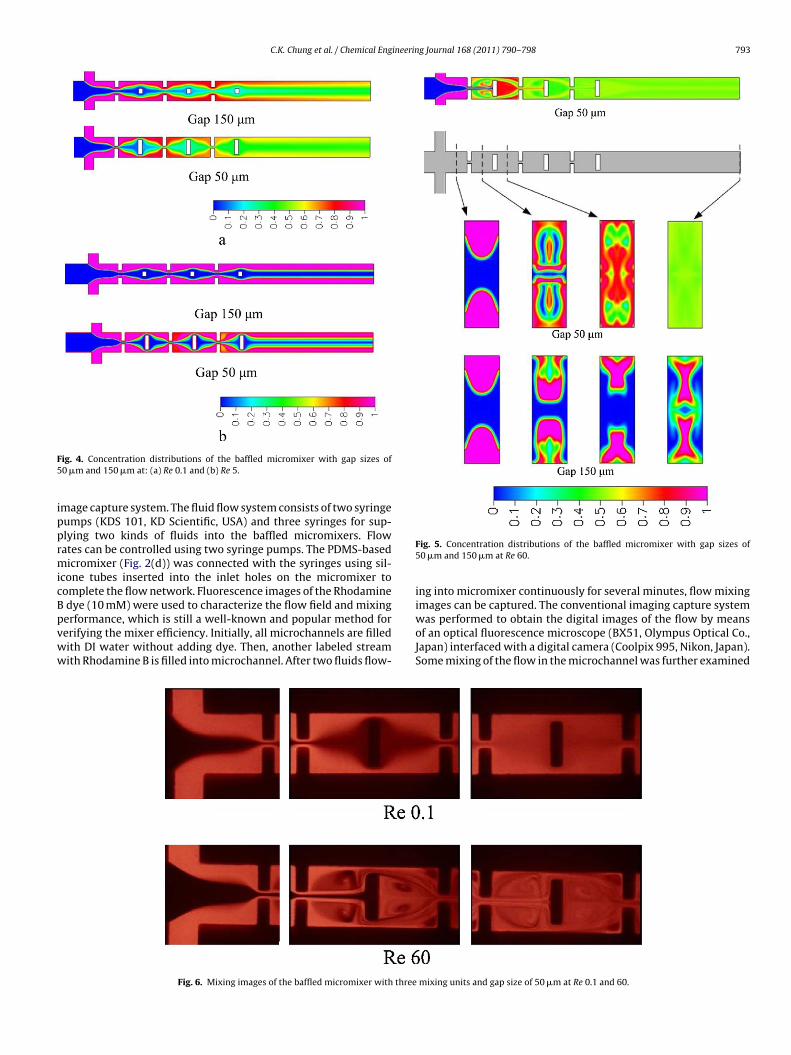
F5
ipprmicBpvww
ig. 4. Concentration distributions of the baffled micromixer with gap sizes of0 �m and 150 �m at: (a) Re 0.1 and (b) Re 5.
mage capture system. The fluid flow system consists of two syringeumps (KDS 101, KD Scientific, USA) and three syringes for sup-lying two kinds of fluids into the baffled micromixers. Flowates can be controlled using two syringe pumps. The PDMS-basedicromixer (Fig. 2(d)) was connected with the syringes using sil-
cone tubes inserted into the inlet holes on the micromixer toomplete the flow network. Fluorescence images of the Rhodaminedye (10 mM) were used to characterize the flow field and mixing
erformance, which is still a well-known and popular method forerifying the mixer efficiency. Initially, all microchannels are filledith DI water without adding dye. Then, another labeled streamith Rhodamine B is filled into microchannel. After two fluids flow-Fig. 6. Mixing images of the baffled micromixer with three
Fig. 5. Concentration distributions of the baffled micromixer with gap sizes of50 �m and 150 �m at Re 60.
ing into micromixer continuously for several minutes, flow mixingimages can be captured. The conventional imaging capture system
was performed to obtain the digital images of the flow by meansof an optical fluorescence microscope (BX51, Olympus Optical Co.,Japan) interfaced with a digital camera (Coolpix 995, Nikon, Japan).Some mixing of the flow in the microchannel was further examinedmixing units and gap size of 50 �m at Re 0.1 and 60.

7 ineering Journal 168 (2011) 790–798
bSTLdwht
4
9(UnfTrabTmam
touaclpsTvTudtib
5
5
pmiaeamvccRrotttc
Fig. 7 (. a) The mixing images of the first two mixing chambers of the micromixer
94 C.K. Chung et al. / Chemical Eng
y cross-sectional images which were captured by using a Leica TCSP2 confocal scanning microscope (Leica Microsystems, Germany).he excitation wavelength is 488 nm from an Argon laser for aeica confocal microscope. From the series of sections at differentepths, 3D image can be reconstructed using the appropriate soft-are. The 3D confocal fluorescence images with Rhodamine B dyeas much improvement of observing mixing efficiency comparedo our previous visualization with 2D ink gray image [24].
. Starting solution and synthesis method
The precursor of tetraethyl orthosilicate (TEOS, Si(OC2H5)49.999% purity, Aldrich Chemical Co., USA), ammonium hydroxide28% NH3 in water, Aldrich Chemical Co., USA), alcohol (Pharm Co.,SA), and DI water were used without further purification for theanoparticle synthesis. Table 1 shows two different recipes used
or silica nanoparticles synthesis at low and high flow rates. HigherEOS concentration was used in low flow rate than in high flowate. Synthesis solutions were then loaded into different syringes,nd equal flow rates were pumped into the microreaction chipy using two syringe pumps (KD Scientific, USA). The solution ofEOS in ethyl alcohol was supplied to the main inlet of the baffledicromixer using one syringe pump. Solution of ammonia, water
nd ethyl alcohol were applied to two side inlets of the baffledicromixer.In order to further analysis the reaction product, a centrifuge
ube was used to collect the synthesis production at the outletf the reaction tube. Then, synthesis production was centrifugedsing a centrifuge (HERMLE, Germany) and washed with ethanolnd DI water in order to avoid possible further reaction by repeatedentrifugation (at 5800 rpm for 5 min). The samples for high reso-ution scanning electron microscopy (HRSEM) investigation wererepared by placing small drops of washed particles solution ontomall silicon pieces (2 mm squares), and drying in an oven at 70 ◦C.he morphology and size of particles were examined and analyzedia micrographs of field emission HR-SEM (JSM-6700, JEOL, Japan).he average size and deviation of particles were analyzed by man-ally counting 100 (larger) and 200 (smaller) particles. The energyispersive X-ray spectroscope (EDS) attached to HR-SEM was usedo analyze the nanoparticles composition. The Fourier transformednfrared (FTIR) spectroscope was also used to examine bondingehavior of silica nanoparticles.
. Results and discussion
.1. Mixing efficiency from simulation
For the baffled micromixer, gap size is important for mixingerformance. In order to understand the effect of gap sizes on theixing, different gap sizes of gap 50 �m and 150 �m, correspond-
ng to gap ratios of 1/8 and 3/8, were investigated by 3D simulationst different Reynolds numbers. Fig. 3 shows the simulate mixingfficiency (M (%)) of the baffled micromixers with gap ratios of 1/8nd 3/8 as a function of Reynolds numbers (Re). The evolution ofixing efficiency can be divided into two regions with a transition
alue around Re 5: (1) Re 0.1–5, diffusion-dominant mixing effi-iency increases with decreasing Reynolds number and, (2) Re 5–60,onvection-dominant mixing efficiency increases with increasingeynolds number. In region (1), as Reynolds number decreases, theesidence time increases and may result in longer diffusion length
f molecules for better mixing. For the baffled micromixer withhe gap 50 �m, the mixing efficiency is 35.7% at Re 5 and increaseso 38.9% at Re 1 and 97% at Re 0.1. As Reynolds number is biggerhan 5, convection effect due to focusing/diverging and vorticesan improve the fluid mixing. Stronger vortices may be generatedat a quarter depth (z = 32.5 �m) and a half depth (z = 65 �m) of the channel at Re60, and (b) the cross-sectional outlet optical images of the micromixer with threemixing units and gap ratio of 1/8 at Re 40 and 60.
by higher Reynolds numbers to enhance mixing. Here 66% mix-ing efficiency is achieved at Re 20 and over 90% mixing is achievedat Re > 40. It indicates that our proposed planar micromixer withshort mixing distance exhibits two operation windows for good
mixing efficiency larger than 90%, that is, at regions of Re < 0.1and Re > 40. As the gap ratio being increased from 1/8 to 3/8, tworegions of evolution of mixing efficiency also exist but fluid mix-ing becomes much worse, especially at high Reynolds number. For
C.K. Chung et al. / Chemical Engineering Journal 168 (2011) 790–798 795
verag
ea3aleTicbnrmpsoadRbilt3
ot(iflTpitimsapimR
Fig. 8. The SEM image of silica nanoparticles with an a
xample, mixing efficiency is 15.5% at Re 5 and increases to 80%t Re 0.1. The mixing efficiency is 16.5% at Re 10 and increases to1% at Re 60. Comparing mixing efficiency at both gap ratios of 1/8nd 3/8, the former exhibits a higher mixing efficiency than theatter at Re < 5 because of its smaller gap ratio and a much higherfficiency at Re > 5 because of its much stronger convection effect.herefore, the lower the gap ratio, the higher the mixing efficiencys. In the design with gap size of 50 �m or gap ratio of 1/8, mixingan be achieved at a wide range of lower and higher Reynolds num-er. With regard to the pressure drop, it increases with Reynoldsumber and is about 12,200 Pa at Re 40 for a good mixing at gapatio of 1/8. The low pressure drop is suitable for integration withicrosystem and is much lower than the conventional 3D or planar
assive micromixers for a good mixing [14–16,21]. In compari-on with the results in our previous simulations at low numberf cells [24], the trend of enhanced mixing efficiency at both lownd high Re from respective diffusion-dominant and convection-ominant mechanisms is similar. The efficiency value at regions ofe ≤ 0.1 and Re ≥ 40 shows a good mixing efficiency of over 90%,ut at 0.5 ≤ Re ≤ 20, it exhibits large deviations due to the numer-
cal diffusion effect. Using second-order differential scheme andarge number of cells for stable solution of 3D model, we are ableo approach the real mixing condition which will be presented byD confocal images in next sub-section.
Species mixing process within mixing chambers with gap sizesf 50 and 150 �m can be observed from the cross-sectional concen-ration distributions along the short mixing channel. Fig. 4(a) andb) shows the concentration distributions of the baffled micromixern diffusion-dominated mixing at Re 0.1 and 5. Initially, two speciesow into the mixing units by means of three inlet-microchannels.he initial concentration distribution shows the worsen mixingrior to the first mixing unit. While three streams were merged
nto one stream through the first gap, fluid is accelerated and intohe first mixing chamber. Fluid mixing is improved in the first mix-ng chamber because of the focusing effect. As fluid leaves the first
ixing chamber and flows through both gaps of the obstacles, maintream is separated as two streams. At the same time, two streams
re accelerated once through the gaps to enhance mixing again. Thiseriodic structure design with three mixing units can effectivelyncrease mixing efficiency. In such a flow field with low velocity,ixing efficiency is related to the residence time. The lower the
eynolds number, the longer the residence time, and the better the
e diameter about 250 ± 50 nm at flow rate of 0.1 ml/h.
mixing efficiency is. Compared to the concentration distributionsat Re 0.1, much poor mixing improvement occurs at Re 5 becauseof less residence time. Besides the residence time, smaller gap sizeis also important for uniform mixing. For a fixed Reynolds num-ber, fluid focusing enhances diffusion effect to improve mixing.As the flow velocity increases into convection-dominated mixing,flow separation and vortices effect could be created within mixingchambers. Fig. 5 shows concentration distributions of various crosssections of the micromixer with gap sizes of 50 �m and 150 �mat Re 60. Prior to the first mixing unit, mixing is very poor. At rela-tively high Reynolds number, flow separation and vortices agitationwithin the first mixing chamber may occur. Therefore, interfacialarea between species will expand due to vortices effect. As fluidflow out the first mixing chamber, fluid is accelerated once moreand vortices are created again because of sudden expansion of themicrochannel. Therefore, the fluid mixing is enhanced once more.The enhanced mixing is repeated as fluids flow through the secondand third mixing units. Much more enhanced mixing is observedfrom concentration distribution at cross section of outlet. As gapsize decreases, the created vortices will extend to a larger zoneand much more species are sucked into the vortices to experienceagitation for enhancing mixing.
5.2. Mixing efficiency from 3D confocal visualization fordye-labeled experiments
Effective mixing at low and high Reynolds number is furtherexplored using dye-labeled mixing experiments via 3D confocalvisualization which has improved the previous visualization with2D ink gray image [24]. Fig. 6 shows the experimental mixingimages of the baffled micromixer with three mixing units and thegap size of 50 �m at Re 0.1 and 60. As discussed in numerical simula-tions, experimental results also show that the efficient and uniformmixing can be achieved at low and high Reynolds number in thisbaffled micromixer with a short mixing length. As Reynolds num-ber is fixed at 0.1, fluid mixing by molecular diffusion is enhancedbecause of the enough residence time and focusing effect. Vortices
or reflow effect with mixing chambers is not induced because oflow flow velocity. The lower the Reynolds number, the longer theresidence time is for better mixing. When the micromixer is oper-ated at Re 60, nearly uniform mixing is also achieved because ofstronger convection effect. Vortices can stir fluid to enhance mix-
796 C.K. Chung et al. / Chemical Engineering Journal 168 (2011) 790–798
F (a) 12f istrib
iwnnr
ig. 9. The SEM images of silica nanoparticles at reaction time and temperature:unction of reaction time; (d) 12.5 min, 55 ◦C and (e) the histogram of particle size d
ng. In this design, the size and intensity of the vortices increaseith increasing Reynolds number. Thus, the higher the Reynoldsumber, the stronger the vortices for a good mixing is. As Reynoldsumber exceeds 60, efficient mixing can be achieved at shorteresidence time due to the enhanced vortices.
.5 min, 25 ◦C; (b) 50 min, 25 ◦C; (c) the histogram of particle size distribution as aution as a function of reaction temperature.
The depth dependent mixing images are further captured by3D confocal fluorescence microscope. Fig. 7(a) shows the mixingimages of the first two mixing chambers of the micromixer at aquarter and a half depth of the channel at Re 60. Cross-sectionalplanes located at z = 32.5 �m and 65 �m correspond to a quarter

C.K. Chung et al. / Chemical Engineering Journal 168 (2011) 790–798 797
Fc
agttFmacsncal
5
talsmts2tahmdtTtRt(ctwtartpsrtnph
ig. 10. The histogram of particle size distribution as a function of ammonia con-entration with weights of 1 g, 2 g and 3 g.
nd a half depth of the channel, respectively. Stronger vortices areenerated within mixing chambers and enhance fluid mixing inhese chambers. The similar images at different depths indicatehat the micromixer has good mixing uniformity along the depth.ig. 7(b) shows the cross-sectional outlet optical images of theicromixer with three mixing units and gap size of 50 �m at Re 40
nd 60. At Re 40, much improved mixing can be achieved because ofonvection effect. As Reynolds number increases from 40 to 60, theize and intensity of the vortices increase with increasing Reynoldsumber as discussed in simulations. Thus, nearly complete mixingan be achieved. It evidences that vortices effect enhances mixingt higher Reynolds number in this micromixer with a short mixingength.
.3. Microreactor for microfluidic synthesis of silica nanoparticles
This high-efficiency baffled micromixer was further applied tohe nanoparticles synthesis at low and high flow rates. The microre-ctor chip in Fig. 2(c) was used to synthesize silica nanoparticle atow flow rate of 0.1 ml/h at room temperature of 25 ◦C. Its corre-ponding Reynolds number is about 0.13 and two streams can beixed by molecular diffusion by means of two solutions listed in
he recipe 1 of Table 1. Fig. 8 shows the SEM micrograph of theynthesized silica nanoparticles with an average diameter about50 ± 50 nm. Synthesis result shows silica nanoparticles can be syn-hesized using this baffled micromixer with short mixing lengtht low flow rate. Besides the particle synthesis at low flow rate,igh-flow-rate synthesis had also been carried out using a PDMSicromixer (Fig. 2(d)) and Teflon reaction tube of 1.5 mm in inner
iameter. Effects of the reaction time and temperature on nanopar-icles synthesis were further investigated using recipe 2 listed inable 1. Fig. 9(a) and (b) shows the SEM images of silica nanopar-icles synthesized at different reaction times of 12.5 and 50 min.eaction temperature is fixed at room temperature of 25 ◦C. At reac-ion time of 12.5 min with a total volumetric flow rate of 35 ml/hor Reynolds number about 45), the smaller average nanoparti-le diameter with deviation of 88 ± 11 nm is obtained. As reactionime being increased to 50 min, larger average particle diameterith deviation of 140 ± 25 nm can be synthesized due to the par-
icle growth effect. The histogram of particle size distribution asfunction of reaction time is shown in Fig. 9(c). The higher the
eaction time, the bigger the particle size is. Besides the effects ofhe residence time on particle synthesis, the effect of reaction tem-erature on particle size is investigated. Recipe 2 is also used toynthesize silica nanoparticle at residence time of 12.5 min cor-
esponding to total volumetric flow rate of 35 ml/h. The reactionemperature increases from 25 ◦C to 55 ◦C. Experimental result ofanoparticle synthesis at 55 ◦C is shown in Fig. 9(d). Smaller averagearticle with deviation of 46 ± 7 nm is achieved. Fig. 9(e) shows theistogram of particle size distribution as a function of reaction tem-Fig. 11. (a) EDS spectrum and (b) FTIR spectrum of the microfluidic synthesizedsilica nanoparticles.
perature. Increasing reaction temperature results in the decrease ofaverage particles size from 88 nm to 46 nm. The nanoparticles withnarrower size distribution of 7 nm can be synthesized at higherreaction temperature of 55 ◦C. The formation of silica particles fromTEOS solution can be expressed by the following two main reactionsin Eqs. (6) and (7) [27]:
Si(OR)4 + 4H2O → Si(OH)4 + 4ROH (Hydrolysis) (6)
Si(OH)4 → SiO2 + 4H2O (Condensation) (7)
where R stands for alkyl group (C2H5). Since the reaction rate ofhydrolysis is slow in the sol–gel process, an acidic or alkalic cat-alyst is used to facilitate the hydrolysis reaction. Here ammoniais used for catalyzing hydrolysis reaction. In microfluidic synthe-sis, a good mixing of two injected solutions in a short mixinglength is favorable for complete reaction. Generally the condensa-tion reaction of silicon hydroxide is much faster than the hydrolysisreaction of silicon alkoxide. As we fix the concentration of waterand ammonia, the synthesis of silica nanoparticles is dominatedby hydrolysis reaction and affected by the flow rate, reaction timeand temperature. In brief, increasing flow rate corresponding todecreasing residence time leads to the smaller particle size, thatis, the 250 ± 50 nm particles formed at low flow rate of 0.1 ml/hand the 88 ± 11 nm ones at high flow rate of 35 ml/h. Increasingthe reaction time for particle growth results in the larger size from88 ± 11 nm to 140 ± 25 nm. Taking into account of the temperatureeffect, increasing reaction temperature can reduce OH− concentra-tion ([Si(OH)4]) in the exothermic hydrolysis reaction and enhance
the nucleation rate from the classical nucleation and growth the-ory [28]. Therefore, the low OH− concentration and high nucleationrate prohibits nuclei from growing into a large particle. That is,a smaller particles size of 46 ± 7 nm is formed at 55 ◦C. Differentconcentrations with ammonia weights of 1 g, 2 g and 3 g for the
7 ineerin
hat5fitcrttnabE(StAaifafllgha
6
armtoathbahprtipstflobc
A
u
[
[
[
[
[
[
[
[
[
[
[
[
[
[
[
[
[
98 C.K. Chung et al. / Chemical Eng
igh-flow-rate synthesis were adopted to investigate the effect ofmmonia concentration on the average particle size and size dis-ribution at 25 ◦C. Residence time of these experiments is fixed to0 min. Fig. 10 shows the histogram of particle size distribution as aunction of ammonia concentration. The average particle diameterncreases from 48 nm to 184 nm with increasing ammonia concen-ration. That is, to minimize the average particle size, the ammoniaoncentration should be decreased. In general, hydrolysis is a sloweaction in the absence of catalyst. Here, ammonia acts as a catalysto accelerate the hydrolysis of TEOS. Higher ammonia concentra-ion is attributed to the higher hydrolysis rate and result in lageranoparticle sizes. At the lowest ammonia concentration, smallerverage diameter of 48 nm and standard distribution of 10 nm cane obtained. The composition of nanoparticles was examined by theDS spectrum as shown in Fig. 11(a). Only silicon (Si) and oxygenO) peaks were detected in EDS spectrum and the atomic ratio ofi/O is 0.46 close to 0.5 for SiO2. The bonding behavior of nanopar-icles was examined by the FTIR spectrum as shown in Fig. 11(b).
strong absorption peak of Si–O bonding was observed. Both EDSnd FTIR results indicate that the nanoparticles are made of sil-ca. Moreover, this simple continuous-flow system offer a methodor smaller particle size with reasonable size distribution synthesist high reaction temperature without using two-phase segmentedow which was generally concerned with the more complicated
iquid–gas control system, operation complexity and compressedas stability. This novel microreactor can potentially be used forigh-throughput microfluidic synthesis for nanomaterial, chemicalnd medical application in future.
. Conclusion
We have demonstrated a simple planar baffled micromixer withshort mixing distance for effective mixing at low and high flow
ates. From the numerical results of 3D simulations and experi-ental confocal flow visualizations, the baffled micromixer with
hree mixing units and a gap size of 50 �m can achieve over 90%f mixing at Re < 0.1 by molecular diffusion or at Re > 40 by chaoticnd convection effect. This micromixer is further integrated intohe microreactor chip for silica nanoparticles synthesis at low andigh flow rates. An average particle diameter of 250 ± 50 nm cane obtained at a low flow rate of 0.1 ml/h. The particle size can bedjusted by means of flow rate, reaction time and temperature. Atigh flow rate of 35 ml/h with lower residence time, the smallerarticles with an average diameter of 88 ± 11 nm were formed at aeaction time of 12.5 min. Both EDS and FTIR results indicate thathe nanoparticles are made of silica. The particle size increases withncreasing reaction time and reduces with increasing reaction tem-erature. The size of particles is reduced to 46 ± 7 nm at 55 ◦C. Themaller particle size with reasonable size distribution can be syn-hesized at high reaction temperature without using segmentedow. This micromixer has the merits of easy fabrications, shortbstacle channel and less mixing units. It also offers the possi-ility of high-throughput microfluidic synthesis for nanomaterial,hemical and medical applications.
cknowledgements
This work is partial sponsored by National Science Council (NSC)nder contract No. NSC 96-2628-E-006-080-MY3 and NSC 98-
[
[
g Journal 168 (2011) 790–798
2221-E-006-052-MY3. We pay our great thanks to the Center forMicro/Nano Science and Technology (CMNST) in National ChengKung University for the access of process and analysis equipments.
References
[1] T. Tsuzuki, P.G. McCormick, ZnO nanoparticle synthesized by mechanochemicalprocessing, Scripta Mater. 44 (2001) 833–837.
[2] B.L. Cushing, V.L. Kolesnichenko, C.J. O’Connor, Recent advances in the liquid-phase syntheses of inorganic nanoparticles, Chem. Rev. 104 (2004) 3893–3946.
[3] C.K. Chung, C.W. Lai, C.C. Peng, B.H. Wu, Formation of SiC nanoparticles of two-layer C/Si films on the Si substrate using thermal annealing, Thin Solid Films517 (2008) 1219–1224.
[4] C.K. Chung, B.H. Wu, Thermal induced formation of SiC nanoparticles fromSi/C/Si multilayers deposited by ultra-high-vacuum ion beam sputtering, Nan-otechnology 17 (2006) 3129–3133.
[5] T. Ogihara, M. Iizuka, T. Yanagawa, N. Ogata, K. Yoshida, Continuous reactorsystem of monosized colloidal particles, J. Mater. Sci. 27 (1992) 55–62.
[6] T. Ogihara, E.M. Ikeda, M. Kato, N. Mizutani, Continuous processing of monodis-persed TiO2 powders, J. Am. Ceram. Soc. 72 (1989) 1598–1601.
[7] T. Yonemoto, M. Kubo, T. Doi, T. Tadaki, Continuous synthesis of titanium diox-ide fine particle using slug flow ageing tube reactor, Trans. Inst. Chem. Eng. A75 (1997) 413–419.
[8] M. Kubo, T. Yonemoto, Continuous synthesis of TiO2 fine particles and increasesof particle size using a two-stage slug tubular reactor, Trans. Inst. Chem. Eng.A 77 (1999) 335–341.
[9] B.K. Paul, V.T. Remcho, S. Atre, J.E. Hutchison, Synthesis and post-processingof nanomaterials using microreaction technology, J. Nanopart. Res. 10 (2008)965–980.
10] A. Gunther, S.A. Khan, M. Thalmann, F. Trachsel, K.F. Jensen, Transport andreaction in microscale segmented gas–liquid flow, Lab Chip 4 (2004) 278–286.
11] K.F. Jensen, Microreaction engineering – is small better? Chem. Eng. Sci. 56(2001) 293–303.
12] S.A. Khan, A. Gunther, M.A. Schmidt, K.F. Jensen, Microfluidic Synthesis of Col-loidal Silica, Langmuir 20 (2004) 8604–8611.
13] S.A. Khan, K.F. Jensen, Microfluidic synthesis of titania shells on colloidal silica,Adv. Mater. 19 (2007) 2556–2560.
14] N.T. Nguyen, Z. Wu, Micromixers – a review, J. Micromech. Microeng. 15 (2005)R1–R16.
15] V. Hessel, H. Löwe, F. Schönfeld, Micromixers – a review on passive and activemixing principles, Chem. Eng. Sci. 60 (2005) 2479–2501.
16] R.H. Liu, M.A. Stremler, K.V. Sharp, M.G. Olson, J.G. Santiago, R.J. Adrian, H. Aref,D.J. Beebe, Passive mixing in a threedimensional serpentine microchannel, J.Microelectromech. Syst. 9 (2000) 190–197.
17] D.S. Kim, S.W. Lee, T.H. Kwon, S.S. Lee, A barrier embedded chaotic micromixer,J. Micromech. Microeng. 14 (2004) 798–805.
18] A.D. Stroock, S.K.W. Dertinger, A. Ajdari, I. Mezic, H.A. Stone, G.M. Whitesides,Chaotic mixer for microchannels, Science 295 (2002) 647–651.
19] C.K. Chung, T.R. Shih, A rhombic micromixer with asymmetrical flow forenhancing mixing, J. Micromech. Microeng. 17 (2007) 2495–2504.
20] C.K. Chung, T.R. Shih, T.C. Chen, B.H. Wu, Mixing behavior of the rhombicmicromixers over a wide Reynolds number range using Taguchi method and3D numerical simulations, Biomed. Microdevic. 10 (2008) 739–748.
21] S.H. Wong, P. Bryant, M. Ward, C. Wharton, Investigation of mixing in a cross-shaped micromixer with static mixing elements for reaction kinetics studies,Sens. Actuators B 95 (2003) 414–424.
22] A.A.S. Bhagat, E.T.K. Peterson, I. Papautsky, A passive planar micromixer withobstructions for mixing at low Reynolds numbers, J. Micromech. Microeng. 17(2007) 1017–1024.
23] S.A. Rani, B. Pitts, P.S. Stewart, Rapid diffusion of fluorescent tracers into Staphy-lococcus epidermidis biofilms visualized by time lapsemicroscopy, Antimicrob.Agents Chemother. 49 (2005) 728–732.
24] T.R. Shih, C.K. Chung, A high-efficiency planar micromixer with convection anddiffusion mixing over a wide Reynolds number range, Microfluid. Nanofluid. 5(2008) 175–183.
25] J. Boss, Evaluation of the homogeneity degree of a mixture, Bulk Solids Handling6 (1986) 1207–1215.
26] S. Bhattacharya, A. Datta, J.M. Berg, S. Gangopadhyay, Studies on surface wet-tability of poly-dimethyl siloxane (PDMS) and glass under oxygen-plasmatreatment and correlation with bond strength, J. Microelectromech. Syst. 14
(2005) 590–597.27] S.K. Park, K.D. Kim, H.T. Kim, Preparation of silica nanoparticles: determinationof the optimal synthesis conditions for small and uniform particles, ColloidsSurf. A 197 (2002) 7–17.
28] D.C. William Jr., Fundamentals of Materials Science and Engineering, 2nd ed.,John Wiley & Sons, NJ, 2005, pp. 420–427.


![C2P11Series[c][3]-SDS UK-English-49.pdf C2P11Series[M][3 ...h22235. · C2P11Series[c][3]-SDS_UK-English-49.pdf C2P11Series[M][3]-SDS_UK-English-50.pdf C2P11Series[Y][3]-SDS_UK-English-44.pdf](https://static.fdocuments.us/doc/165x107/5ecec9de69da9b61c35fd5d3/c2p11seriesc3-sds-uk-english-49pdf-c2p11seriesm3-c2p11seriesc3-sdsuk-english-49pdf.jpg)