3M Iron Man Plus Workstation Monitor CTC331documents.staticcontrol.com/pdf/TD-CTC331-WW.pdf · 7...
16
User’s Guide 3M ™ Iron Man Plus Workstation Monitor CTC331
Transcript of 3M Iron Man Plus Workstation Monitor CTC331documents.staticcontrol.com/pdf/TD-CTC331-WW.pdf · 7...

User’s Guide
3M™ Iron Man Plus Workstation Monitor CTC331

2
Table of Contents
Section Page
1.0 Safety Information .......................................................................................3
Intended Use ................................................................................................3
2.0 Environmental Conditions ...........................................................................5
3.0 Package Contents .........................................................................................5
4.0 General Product Specifications ....................................................................6
5.0 Operation ......................................................................................................6
6.0 Installation ....................................................................................................8
7.0 Verification Procedures ..............................................................................12
8.0 Replacing the Wrist Strap Input Jack .........................................................12
9.0 Accessory Items .........................................................................................13
Regulatory Information .......................................................................................14
Warranty ..............................................................................................................16

3
1.0 Safety Information Read, understand, and follow all safety information contained in this user guide prior to installation and use of the 3M™ Iron Man Plus Workstation Monitor CTC331. Retain this guide for future reference.
Intended UseThe Iron Man Plus Workstation Monitor:• Monitors a voltage level that is being generated on a printed circuit board
while working on it.• Monitors resistance to ground of a conductive or dissipative static
control type of work surface.• Monitors resistance and voltage on a dual conductor wrist strap while being
worn by a person.
The monitor operates with World Wide Universal AC power adapter model CTA212.
Explanation of Signal Word Consequences
WARNING Indicates a hazardous situation which, if not avoided, could result in
death or serious injury.
CAUTION Indicates a potentially hazardous situation which, if not avoided, could result in minor or moderate injury and/or property damage.
NOTICE Indicates a situation which, if not avoided, could result in property damage.
Summary of Device Labels Containing Safety Information
Ground Double insulation
Direct Current Terminal
Caution For Indoor Use Only
4
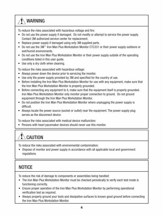
WARNING
To reduce the risks associated with hazardous voltage and fire:• Do not use the power supply if damaged. Do not modify or attempt to service the power supply.
Contact 3M authorized service center for replacement.• Replace power supply if damaged using only 3M supplied parts.• Do not use the 3M™ Iron Man Plus Workstation Monitor CTC331 or their power supply outdoors or
wet/humid environments.• Do not use the Iron Man Plus Workstation Monitor or their power supply outside of the operating
conditions listed in this user guide.• Use only a dry cloth when cleaning.
To reduce the risks associated with hazardous voltage:• Always power down the device prior to servicing the monitor.• Use only the power supply provided by 3M and specified for the country of use.• Before installing the Iron Man Plus Workstation Monitor for use with any equipment, make sure that
the Iron Man Plus Workstation Monitor is properly grounded.• Before connecting any equipment to it, make sure that the equipment itself is properly grounded.
Iron Man Plus Workstation Monitor only monitor proper connection to ground. Do not ground equipment through the Iron Man Plus Workstation Monitor.
• Do not position the Iron Man Plus Workstation Monitor where unplugging the power supply is difficult.
• Always locate the power source (socket or outlet) near the equipment. The power supply plug serves as the disconnect device.
To reduce the risks associated with medical device malfunction: • Persons with heart pacemaker devices should never use this monitor.
To reduce the risks associated with environmental contamination:• Dispose of monitor and power supply in accordance with all applicable local and government
regulations.
CAUTION
To reduce the risk of damage to components or assemblies being handled:• The Iron Man Plus Workstation Monitor must be checked periodically to verify each test mode is
functioning correctly.• Ensure proper operation of the Iron Man Plus Workstation Monitor by performing operational
verification test as required. • Always properly ground your tools and dissipative surfaces to known good ground before connecting
the Iron Man Plus Workstation Monitor.
NOTICE

5
2.0 Environmental ConditionsThis equipment has been tested and found to be safe to operate within these environmental conditions. This is not a warranty of equipment performance within these conditions.
Indoor use only
Ingress Protection: IPX0
Altitude: Up to 2,000 m
Mains supply voltage fluctuations up to ± 10% of the nominal voltage.
Transient overvoltage up to the levels of overvoltage category II.
Temporary overvoltage occurring on mains supply.
Pollution degree 2.
Temperature: Maximum 110°F / 43°C Minimum 50°F / 10°C
Humidity: Maximum relative humidity 80% for temperatures up to 31°C decreasing linearly to 50% relative humidity at 40°C .
3.0 Package ContentsThe 3M™ Iron Man Plus Workstation Monitor CTC331 package should include the following*:
Package Contents
3M™ Iron Man Plus Workstation Monitor 1 ea
Yellow wire with alligator clip 30 in.(76.2 cm) length 1 ea
Product User’s Guide 1 ea
Power Supply Unit 1 ea
If any of the items are missing, please contact 3M, 1-866-722-3736, or one of 3M authorized distributors immediately.*Note: Packages containing custom configurations will contain items not included on this typical list.

6
4.0 General Product Specifications
Properties Value
Power
AC/DC Adapter Universal: 100 - 240VAC, 0.5A, ~ 50/60 Hz Output: 12VDC,1.5A
Overvoltage Alarm
Alarm Threshold Ranges 0 to ± 5V (default set point); 0 to ± 50V typical
Threshold Adjustment Potentiometer
Threshold Range Range selected by jumper
Operator Grounding
Wrist Strap Dual, 3.0 mm plugNumber of Wrist Straps monitored 1
Body Resistance Alarm Level 10 MΩ typical
Body Voltage Alarm Level ± 2.5V typical (Default)
Mat
Monitoring Mat grounding Yes
Alarm
Visual LED
Audio Buzzer
General
Dimensions (approx) 0.85" H x 2.4" W x 2.6" L22 mm H x 61 mm W x 66 mm L
5.0 OperationThe 3M™ Iron Man Plus Workstation Monitor CTC331 can be used at most workstations with manual assembly and testing activity. It has the following three functions - 1) Over-voltage monitor, 2) Mat monitor, and 3) Wrist strap monitor. The unit uses green and red LED’s visual indicators and an audible alarm.
Printed Circuit Board Over-voltage MonitorThe Iron Man Plus Workstation Monitor continuously monitors the voltage level between ground and a printed circuit board (PCB) while in contact with the ground plane, any grounded part of the PCB, or of the product in process. The

7
3M™ Iron Man Plus Workstation Monitor CTC331 uses a potentiometer located at the back of the unit which allows adjustment of the voltage alarm level.
When a soldering iron, tweezers, or other type of tool touches the grounded pad of a board, the Iron Man Plus Monitor will alarm if overvoltage was introduced onto the PCB. If a soldering iron is not grounded properly, the components on a PCB can be subjected to an overvoltage that can cause component damage. When the voltage (AC or DC) on the PCB exceeds the preset level, the alarm and red LED activate. If the operator is not grounded and holding a tweezers to touch a PCB, the tweezers may also induce a damaging discharge.
Overvoltage conditions generate an electrostatic overstress (EOS) or electrostatic discharge (ESD) event. To prevent this, 1) conductive objects, tools, and personnel need to be grounded properly, 2) non-conductive objects must be neutralized by ionization and remain in a neutral state, and 3) surface materials must dissipative and connected to ground.
Work Surface Ground Resistance MonitorThe Iron Man Plus Workstation Monitor continuously monitors the resistance between ground and the ESD work surface. The dissipative work surface must be grounded using the recommended means. The Iron Man Plus Workstation Monitor does not ground dissipative surfaces; it only monitors proper grounding of such surfaces. If the resistance of the conductive path from such dissipative surface to ground exceeds the threshold, the alarm will activate. There is a slight delay in time before the alarm activates.
Voltage on Person Wrist Strap MonitorThe Iron Man Plus Workstation Monitor continuously monitors the voltage on a person through the dual conductor wrist strap. The loop resistance is monitored, which includes the resistance of the operator’s wrist between the two halves of the wrist band.
Overvoltage Alarm LevelThe alarm level can be adjusted for Lo or Hi ranges. This setting is selected by moving an internal jumper socket inside the unit. the Iron Man Plus Workstation Monitor will respond to either a positive or negative voltage. If the voltage is higher than the pre-set level, a visual red LED and audible alarm are activated. The alarm will be on for at least 1 second. If the voltage level is below the preset alarm level, a green LED lamp remains on. A wire must be attached from the Iron Man Plus monitor to a ground plane of PCB or a fixture to complete the monitoring system.

8
PerformanceWork Surface Ground Resistance Monitor -The alarm level is factory programmed. When the alarm is activated, the red LED indicates that the ground path resistance for the work surface has either increased beyond preset level or is disconnected.
Person Voltage and Resistance Monitor - The alarm level is monitored when a person is wearing a dual conductor wrist strap and plugged into the front jack. The 3M™ Iron Man Plus Workstation Monitor will respond to either a positive or negative voltage. There is a short hold on the body voltage alarm so that it is not missed. The alarm is also activated when the wrist strap is worn too loosely and the loop resistance level is exceeded.
Enabling and Disabling Audible Alarm - The audible alarm can be enabled or disabled by momentarily pressing a recessed miniature push-button Set switch located on the back of the unit. Use of a small wire form allows activation of the switch.
6.0 Installation
Accessories (e.g. Soldering Iron or Tool), Mat, and Operator Green LED - OK Red LED - OverLimit
Wrist Strap Input Jack
Wrist Strap Input Jack
AC/DC Adapter Wrist Strap Input Jack
Wrist Strap Input Jack

9
PlacementSet the 3M™ Iron Man Plus Workstation Monitor CTC331 in a clearly visible, convenient location where it does not interfere with normal work.
Connecting Reference GroundPrepare an 18 AWG wire. Strip off the wire insulation approximately 8 mm (1/3" in) at each end of the wire. Twist the stranded wire on each end. In order to attach the wire to the Iron Man Plus Workstation Monitor, insert a small blade screwdriver into the orange slot above the reference ground connector. Gently push inward and insert the stripped wire fully into the hole in the green connector. Release the screwdriver to allow the wire to catch. Attach the other end of the reference ground wire to a known-good-ground in the area.
Connecting Mat Work SurfacePrepare an 18 AWG wire. Strip off the wire insulation approximately 8 mm (1/3" in) at each end of the wire. Twist the stranded wire on each end. In order to attach the wire to the Iron Man Plus Workstation Monitor, insert a small blade screwdriver into the orange slot above the Mat connector. Gently push inward and insert the stripped wire fully into the hole in the green connector. Release the screwdriver to allow the wire to catch. Use the suppliers recommended method to connect the mat work surface to the other end of the wire.
Connecting Cable to Board Under Test Attach the provided cable with alligator clip in the Iron Man Plus Workstation Monitor package to the back of the Iron Man Plus Workstation Monitor.
Power Adapter
Facility ground baror other good known ground
Connect the alligator clip to anypoint on the ground plane of the board
Example of Ground plane point

10
In order to attach the wire to the 3M Iron Man Plus Workstation Monitor CTC331, insert a small blade screwdriver into the orange slot above the Out connector. Gently push inward and insert the stripped wire fully into the hole in the green connector. Release the screwdriver to allow the wire to catch. Attach the other end of the cable to the board under test or assembly using the alligator clip
Connecting PowerTo use the Iron Man Plus Workstation Monitor, plug the power adapter into the power outlet and plug the cord into the 3M™ Iron Man Plus Workstation Monitor CTC331.
MountingDetermine the mounting location of the Iron Man Plus Workstation Monitor.Attach unit using one of the following recommended methods:• Screws• 3M™ Dual Lock™ FastenerNote: Orientation of the panels can be reversed.
Enabling and Disabling Monitoring of Work Surface Follow these procedures to disable the monitoring of the work surface mat. No jumpers or shunts are required for this device. 1. Unplug the DC input from the device. 2. Remove or do not insert any wire in the Mat connector.3. Using a thin pin, such as a paper clip, press and hold the Setup button.4. While the button is pressed, plug in the DC input and then release the Setup
button.5. Wait for about 30 seconds until the unit recognizes the absence of a mat. The
unit will beep and the Mat LED will be off.6. To re-enable mat monitoring, follow the same procedure except connect the
mat to the Mat input in step 2.
Selecting Lo or Hi Alarm LevelFollow these procedures to change the sensitivity range for overvoltage monitoring. The 3M™ Iron Man Plus Workstation Monitor default setting is high sensitivity (0…+/-5V range). User should be grounded wearing a wrist strap grounding system before disassembly of the Iron Man Plus monitor.

11
1. Remove the two screws using Philips screwdriver #1 from the front plate.
2. Slide the internal board assembly out. Be careful with the removable daughter PCB.
3. Locate Hi - Lo 3-pin header connector on the main board.
4. To select the Lo setting, position the shunt between the center pin and the Lo pin.
5. For the Hi setting, position the shunt between the center pin and the Hi pin.
6. Slide the printed circuit board back into the housing and replace front cover screws.
Adjustment of Voltage Alarm LevelThese following procedures can be used to adjust the voltage alarm level of the 3M™ Iron Man Plus Workstation Monitor CTC331.1. A DC Variable Power Supply with output of 0 to 50V Range is required2. Adjust DC power supply output to 0 initially.3. Plug in AC/DC adapter and turn the Ironman Plus Workstation monitor unit
on. 4. Turn the monitor voltage Threshold Adjust fully clockwise using a small
screwdriver.5. Connect the monitor ground wire to the Common output of the DC power
supply.6. Connect the monitor Board wire to the V output of the DC power supply.7. Turn on the DC power supply and set the output to the required alarm level.8. Slowly turn the monitor alarm potentiometer counterclockwise until the
audible alarm and red LED activates.9. Plug in power and resume to normal operation.

12
7.0 Verification ProceduresUse these procedure outlined below to verify that the unit is operating at the desired settings
Verification of Work Surface monitoring1. 3M™ Workstation Monitor Checker CTE701A is required2. Disconnect the wire connected to Mat. 3. Connect the ground input of the checker to the ground
connector of the 3M Iron Man Plus Workstation Monitor. Set the checker to a proper Soft Ground alarm level (see the Workstation Monitor Checker User’s Guide).
4. Connect the red wire tip of the checker to the Mat terminal. The red LED of Mat should remain on
5. Press the Soft Ground button on the checker. The green LED of Mat should turn on.
Verification of Wrist Strap monitoring1. Connect the 3.5 mm test cable to both the checker and to the operator jack of
the monitor. At this point the monitor should indicate failure.2. Press the Wrist strap button on the Checker. The monitor should show a
green LED on.3. While pressing the Wrist strap button, press body voltage “high.” The
monitor should show a green LED on, and a blinking red LED.4. If all conditions are met, the monitor is operating normally. Reconnect all
wires and power to resume operations.
8.0 Replacing the Wrist Strap Input JackIf the wrist strap input jack begins to show wear and tear damage, it can be replaced using the following procedure. 1. Unplug the DC power.2. The jack can be accessed from the front of the unit. Remove the collar nut on
the input jack.3. Unscrew the two philip-head screws and remove the front cover.4. Pull the two PCB towards the front.5. Pull and lift up the smaller PCB with the input jack. Replace with a new unit
of 3M™ Replacement Board with Wrist Strap Jack 6. Push the 2 PCB back through its slotted guide.7. Place the front cover back and secure with two philip-head screw.8. Secure the collar nuts into the input jack.9. Plug in power and resume to normal operation.

13
9.0 Accessory Items2380 3M™ Monitor/Table Mat Cord, 6 ft.
2368 3M™ Dual Conductor Fabric Wrist Band, Adjustable
2360 3M™ Dual Conductor Ground Cord, Coiled, 5 ft.
2370 3M™ Dual Conductor Ground Cord, Coiled, 10 ft.
CTE701A 3M™ Workstation Monitor Checker
CTA251 3M™ Replacement Board with Wrist Strap Jack
Contact 3M Electronic Material Solutions Division Customer Service Depart-ment at 1-866-722-3736.

14
Regulatory InformationChina RoHSElectronic Industry Standard of the People’s Republic of China, SJ T11363-2006, Requirements for Concentration Limits for Certain Hazardous Substances in Electronic Information Products
This symbol, per Marking for the Control of Pollution Caused by Electronic Information Products, SJ/T11364-2006, means that the product or part does contain a substance, as detailed in the chart below, in excess of the following maximum concentration values in any homogeneous material: (a) 0.1% (by weight) for lead, mercury, hexavalent chromium, polybrominated biphenyls or polybrominated diphenyl ethers; or (b) 0.01% (by weight) for cadmium. Unless otherwise stated by 3M in writing, this information represents 3M’s best knowledge and belief based upon information provided by third party suppliers to 3M.
Name and Content of Hazardous Substances or Elements
Part or Component NameHazardous Substances or Elements
(Pb) (Hg) (Cd) (Cr (VI) (PBB) (PBDE)
Termination in capacitor 0603
Solder in diode
Finish in diode
Terminations in PCBs
Terminations in resistors 0603
Plating in resistors 0603
Resistor ink in potentiometer
Solder in instrument
Solder in IC
Solder in buzzer
Audio jack
X O O O O O
X O O O O O
X O O O O O
X O O O O O
X O O O O O
X O O O O O
X O O O O O
X O O O O O
X O O O O O
X O O O O O
X O O O O O
O: Indicates that this hazardous substance contained in all of the homogeneous materials for this part is below the limit requirement in the SJ/T11363-2006.X: Indicates that this hazardous substance contained in at least one of the homogeneous materials used for this part is above the limit requirement in the SJ/T11363-2006.
15
产品中有毒有害物质或元素的名称及含量
部件名称有毒有害物质或元素
铅 汞 镉 六价铬 多溴联苯 多溴二苯醚
0603电容引脚
二极管焊接部
二极管电镀
印刷电路板焊盘/安装孔
0603 电阻引脚
0603 电阻电镀部
电位器中的电阻油墨
装置的焊接部
IC焊接部
蜂鸣器焊接部
音频插孔
X O O O O O
X O O O O O
X O O O O O
X O O O O O
X O O O O O
X O O O O O
X O O O O O
X O O O O O
X O O O O O
X O O O O O
X O O O O O
O: 表示该有毒有害物质在该部件所有均质材料中的含量均在SJ/T11363-2006 标准规定的限量要求以下。X: 表示该有毒有害物质至少在该部件的某一均质材料中的含量超出SJ/T11363-2006 标准规定的限量要求。
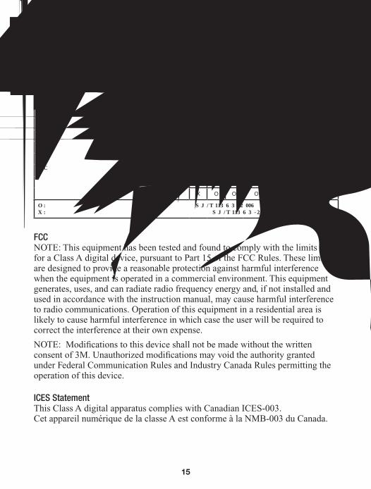
FCCNOTE: This equipment has been tested and found to comply with the limits for a Class A digital device, pursuant to Part 15 of the FCC Rules. These limits are designed to provide a reasonable protection against harmful interference when the equipment is operated in a commercial environment. This equipment generates, uses, and can radiate radio frequency energy and, if not installed and used in accordance with the instruction manual, may cause harmful interference to radio communications. Operation of this equipment in a residential area is likely to cause harmful interference in which case the user will be required to correct the interference at their own expense.
NOTE: Modifications to this device shall not be made without the written consent of 3M. Unauthorized modifications may void the authority granted under Federal Communication Rules and Industry Canada Rules permitting the operation of this device.
ICES StatementThis Class A digital apparatus complies with Canadian ICES-003.Cet appareil numérique de la classe A est conforme à la NMB-003 du Canada.

3
Electronics Materials Solutions DivisionStatic Control Products926 JR Industrial DriveSanford, NC 27332-9733Toll-Free: 866-722-3736International: 919-718-0000Email: [email protected]
Please recycle. Printed in USA.© 3M 2014. All rights reserved.78-9100-3252-9B JHA
Important NoticeAll statements, technical information, and recommendations related to 3M’s products are based on information believed to be reliable, but the accuracy or completeness is not guaranteed. Before using this product, you must evaluate it and determine if it is suitable for your intended application. You assume all risks and liability associated with such use. Any statements related to the product which are not contained in 3M’s current publications, or any contrary statements contained on your purchase order shall have no force or effect unless expressly agreed upon, in writing, by an authorized officer of 3M.
Warranty; Limited Remedy; Limited Liability.This product will be free from defects in material and manufacture for one year from the time of purchase. 3M MAKES NO OTHER WARRANTIES INCLUDING, BUT NOT LIMITED TO, ANY IMPLIED WARRANTY OF MERCHANTABILITY OR FITNESS FOR A PARTICULAR PURPOSE. If this product is defective within the warranty period stated above, your exclusive remedy shall be, at 3M’s option, to replace or repair the 3M product or refund the purchase price of the 3M product. Except where prohibited by law, 3M will not be liable for any indirect, special, incidental or consequential loss or damage arising from this 3M product, regardless of the legal theory asserted.
3M and Dual Lock are trademarks of 3M Company.
WEEE StatementThe following information is only for EU-members States: The mark shown to the right is in compliance with Waste Electrical and Electronic Equipment Directive 2002/96/EC (WEEE). The mark indicates the requirement NOT to dispose the equipment as unsorted municipal waste, but use the return and collection systems according to local law.
CE StatementMeets CE (European Confomity) requirements.
cULus StatementMeets cULus requirements.