3i< USAAVLABS TECHNICAL REPORT 68-49C AN … · phase investigation of the dynamic stability...
83
I ll 3i< QO USAAVLABS TECHNICAL REPORT 68-49C AN INVESTIGATION OF THE DYNAMIC STABILITY CHARACTERISTICS OF A QUAD CONFIGURATION, DUCTED-PROPELLER V/STDL MODEL VOLUME III FINAL DATA REPORT PHASE III - LATERAL/DIRECTIONAL DYNAMICS AT HIGH DUCT INCIDENCES •r lilli» F. Pitui bsipl I. Tiiibif Inarf C. Cirtiss, Ir. Iiki f. Kiln Nnrabi IM U. S. ARMY AVIATION MATERIEL LABORATORIES FORT EUSTIS, VIRGINIA CONTRACT DAAJ02-67-C-0025 PRINCETON UNIVERSITY PRINCETON, NEW JERSEY O (- Thi$ document has been approved for public release and sale; its distribution it unlimited. rEöö ms *\ Uu 1 & f I N G H O U S l .in. -, i, ' ,. '<- . ••mmmi^Mt'Ut -,»-.. Miy
Transcript of 3i< USAAVLABS TECHNICAL REPORT 68-49C AN … · phase investigation of the dynamic stability...

I
ll
3i<
QO
USAAVLABS TECHNICAL REPORT 68-49C AN INVESTIGATION OF THE DYNAMIC
STABILITY CHARACTERISTICS OF A QUAD CONFIGURATION, DUCTED-PROPELLER V/STDL MODEL
VOLUME III
FINAL DATA REPORT PHASE III - LATERAL/DIRECTIONAL DYNAMICS
AT HIGH DUCT INCIDENCES •r
lilli» F. Pitui bsipl I. Tiiibif
Inarf C. Cirtiss, Ir. Iiki f. Kiln Nnrabi IM
U. S. ARMY AVIATION MATERIEL LABORATORIES FORT EUSTIS, VIRGINIA
CONTRACT DAAJ02-67-C-0025 PRINCETON UNIVERSITY
PRINCETON, NEW JERSEY
O (-
Thi$ document has been approved for public release and sale; its distribution it unlimited.
rEöö ms *\
Uu
1 & f I N G H O U S l ■ .in. -, i, ' ,.
'<- . ••mmmi^Mt'Ut -,»-.. Miy
Disclaimers
The findings in this report are not to be construed as an official Depart- ment of the Army position unless so designated by other authorized documents.
When Government drawings, specifications, or other data are used for any purpose other than in connection with a definitely related Govern- ment procurement operation, the United States Government thereby in- curs no responsibility nor any obligation whatsoever; and the fact that the Government may have formulated, furnished, or in any way supplied the said drawings, specifications, or other data is not to be regarded by implication or otherwise as in any manner licensing the holder or any other person or corporation, or conveying any right 3 or permission to manufacture, use, or sell any patented invention that may in any way be related thereto.
Trade names cited in this report do not constitute an offical endorsement or approval of the use of such commercial hardware or software.
Disposition Instructions
Destroy this report when no longer needed. Do not return it to the originator.
^.oc *»(rf iCtTIOt
wtmrm
DEPARTMENT OF THE ARMY U. S. AKMY AVIATION MATCMCL LABORATORIES
FORT CUSTW. VIRGINIA 23604
This report has been reviewed by the U. S. Army Aviation Materiel Laboratories, the Naval Air Systems Conmand, and the Air Force Flight Dynamics Laboratories. It Is considered to be technically sound.
This work, which was performed under Contract DAAJ02-67-C-0025, was undertaken to determine experimentally the lateral/directional dynamic stability characteristics of a quad configuration, four- duct V/STOL aircraft similar to the X-22A configuration at low speeds and high duct Incidences. The Princeton Dynamic Model Track was utilized to perform the Investigation.
This report Is published for the exchange of Information and the stimulation of ideas.
Task 1F16220J4A1U233 Contract DAAJ02-67-C-0025
USAAVLABS Technical Report 68-49C
November 1968
AN INVESTIGATION OF THE DYNAMIC STABILITY CHARACTERISTICS OF A QUAD
CONFIGURATION, DUCTED-PROPELLER V/STOL MODEL
Volume III
Final Data Report Phase III - Lateral/Directional Dynamics at High Duct Incidences
Aerospace Sciences Report 847
By
William F. Putman Joseph J. Traybar
Howard C. Curtiss, Jr. John P. Kukon
Prepared by
Department of Aerospace and Mechanical Sciences Princeton University Princeton, New Jersey
for
U. S. ARMY AVIATION MATERIEL LABORATORIES FORT EUSTIS, VIRGINIA
This document has been approved for public release and sale; its distribution is unlimited.

I SUMMARY
The results of experiments to determine the lateral/directioned dynamic stability characteristics of a quad configuration, ducted-propeller v/STOL aircraft at four low-speed/high-duct-incidence trim conditions (i, = 80° ,
70 , 60°, and 50° ) are presented. Lateral/directional transient responses in various degrees of freedom were measured using a dynamic model on the Princeton Dynamic Model Track. The data presented include time histories of the model motions in various lateral/directional degrees ^f freedom that occur when the model is disturbed from trimmed flight.
The dynamic model employed in these experiments is a generalized research model arranged to represent closely the Bell X-22A v/STOL aircraft.
The data presented in this report comprise the third phase of a three- phase investigation of the dynamic stability characteristics of a quad configuration, ducted-propeller V/STOL aircraft at low speeds and high duct incidences. The other two phases pertain to the lateral and longi- tudinal hovering stability characteristics, presented in Reference 1, and the longitudinal characteristics at four low-speed/high-duct-incidence trim conditions presented in Reference 2.
iii

• i ^B
FOREWORD
This research was performed by the Department of Aerospace and Mechanical Sciences, Princeton University, under the sponsorship of the United States Army Aviation Materiel Laboratories Contract DAAJ02-67-C-0025, with financial support from the United States Naval Air Systems Command and the Air Force Flight Dynamics Laboratory. The research was monitored by Mr. Robert P. Smith of the United States Army Aviation Materiel Laboratories.
The research was directed by Associate Professor H. C. Curtiss, Jr., and was conducted by Messrs. W. F. Putman, J. J. Traybar, and J. P. Kukon, all of Princeton University.
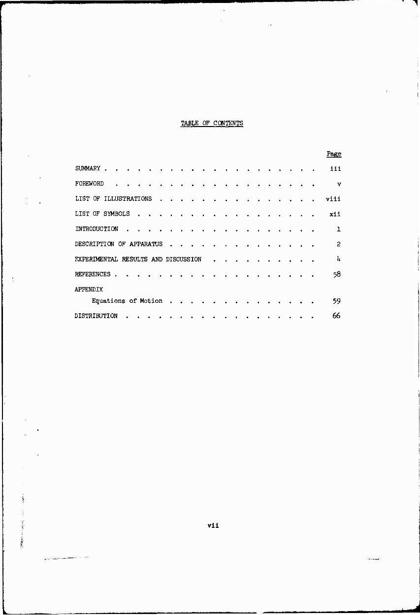
TABLE OF CONTENTS
Page
SUMMARY iii
FOREWORD v
LIST OF ILLUSTRATIONS viii
LIST OF SYMBOLS xii
INTRODUCTION 1
DESCRIPTION OF APPARATUS 2
EXPERIMENTAL RESULTS AND DISCUSSION k
REFERENCES 58
APPENDIX
Equations of Motion 59
DISTRIBUTION 66
vll

LIST OJ? ILLUSTRATIONS
Figure
1
2
3
k
5
6
7
8
9
10
11
Page
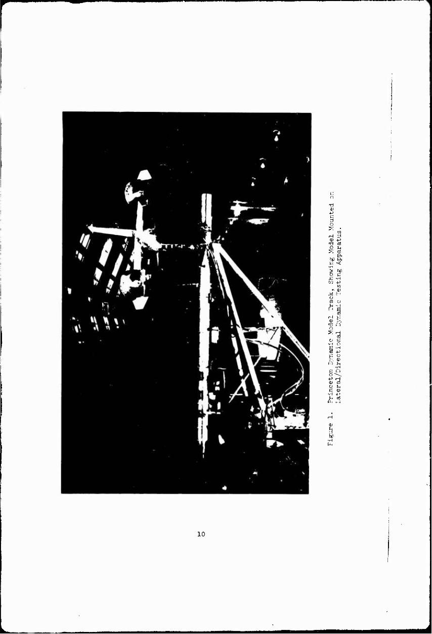
Princeton Dynamic Model Track, Showing Model Mounted on Lateral/Directional Dynamic Testing Apparatus 10
0.lU5-Scale Quad Configuration Dynamic Model. ... 11
General Arrangement, Quad Configuration Dynamic Model 12
Model Reference Stations, Location of Model Center of Gravity and Axes Systems. 13
Geometric Characteristics of Ihree-Bladed Model Propellers. lb
Geometric Characteristics of Scaled Model Ducts 15
Geometric Characteristics and Reference Locations for Model Duct System 16
Experimental Data, Model Trim Conditions. Model Lift = 51-5 lb, rpm = 6780 17
Lateral Transient Response. One Degree of Freedom, <h, id = 80° , ß.7„ = 25.26 , Aß0 = 1.6° ,
Small Vertical Tail, Spring Restrained 18
Directional Transient Response. One Degree of Freedom, Y. id = 80°, P.™, = 25.2°, AP0 = 1.5°,
Small Vertical Tail, Spring Restrained 19
Lateral/Directional Transient Response. Two Degrees of Freedom, 0-¥. id = 80° , U0 =10 ft/sec, ß.7BR = 25.2° ,
rpm = 678O, Aß = 0.5°,
Large Vertical Tail 20
viii
■EflM

-^
Figure
12
13
14
15
16
17
18
Page
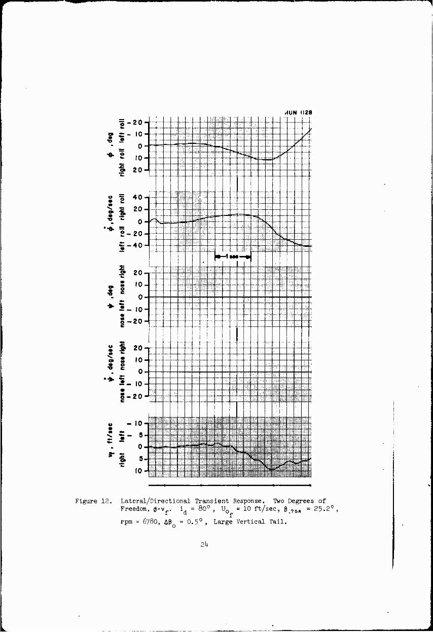
Lateral/Directional Transient Response. IVro Degrees of Freedom, 0-V-.
i = 80°, U0 = 10 ft/sec, P.7B), = 25.2°, a f
rpm = 6780, APo = 0.5° ,
Large Vertical Tail 21
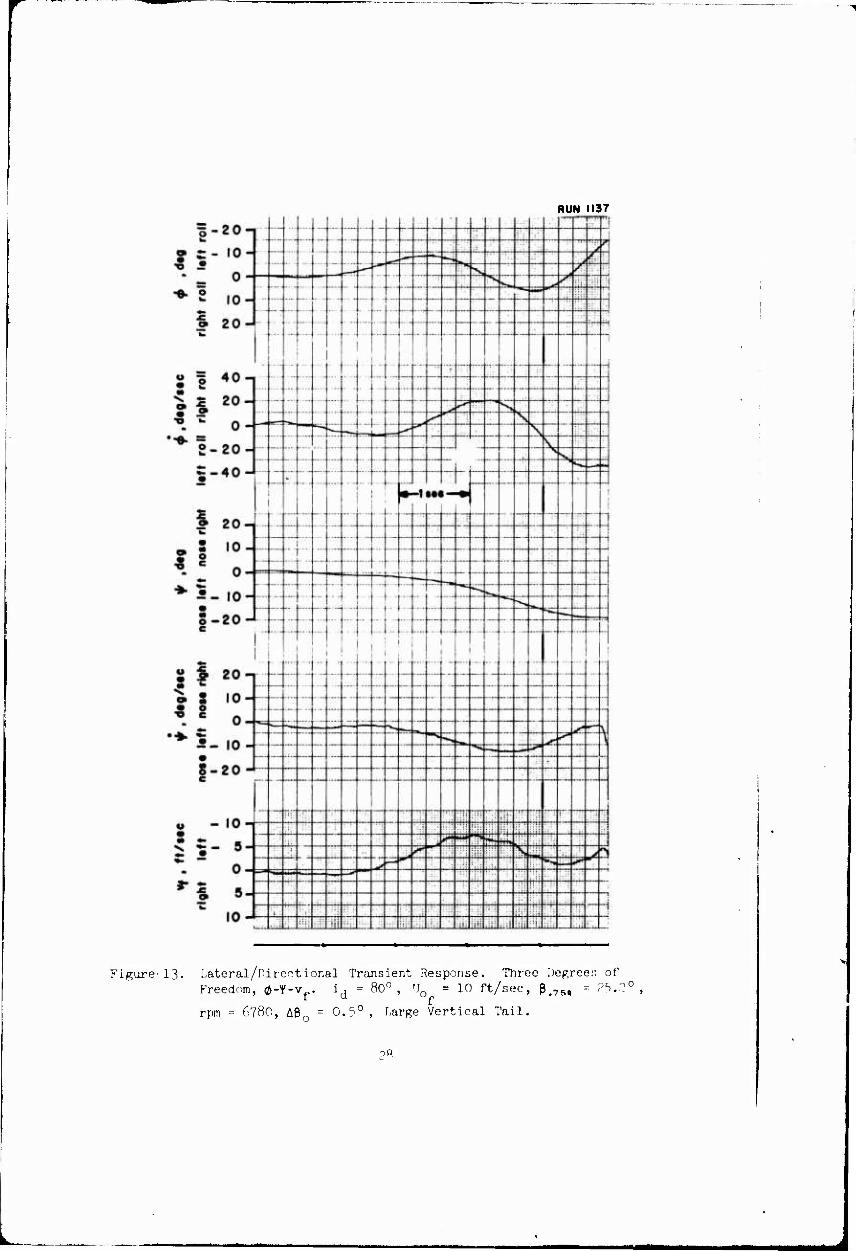
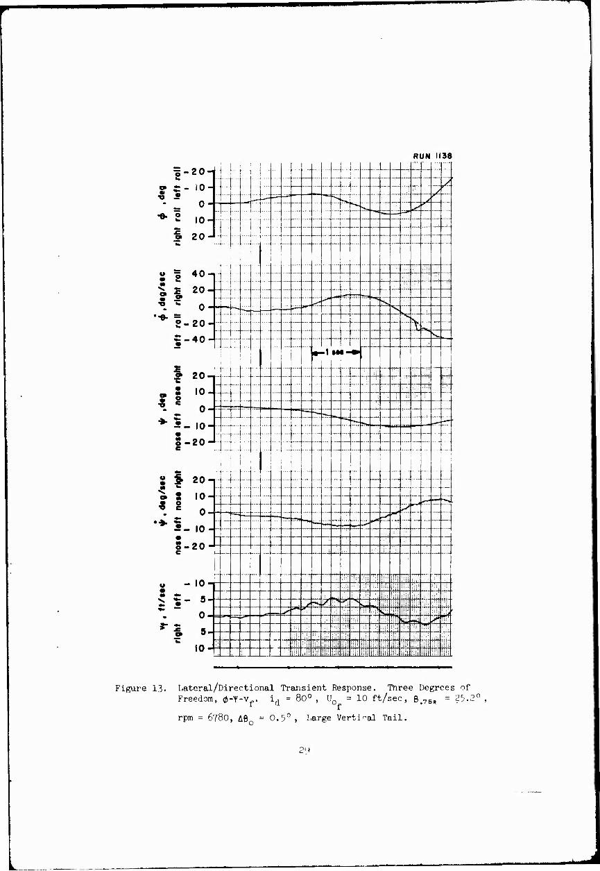
Lateral/Directional Transient Response. Three Degrees of Freedom, 0-1'-v». id - 80° , U0 =10 ft/sec, P.,!, = 25.2° ,
rpm = 678O, Aßo = 0.5° ,
Large Vertical Tail 27
Lateral Transient Response. One Degree of Freedom, 0. id = 70°, p.7BR =26.4°, Ap0 = 5.0°, Small Vertical Tail, Spring Restrained 30
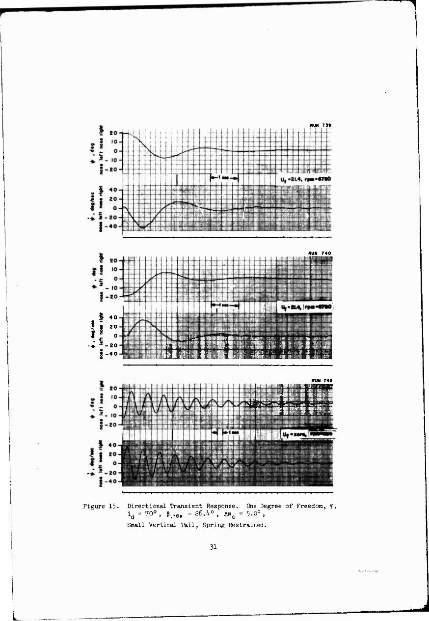
Directional Transient Response. One Degree of Freedom, t. id = 70°, P.™, =26.4°, Aß0 = 5.0°,
Small Vertical Tail, Spring Restrained 31
Lateral/DirectioneLL Transient Response. One Degree of Freedom, Y. id = 70°, U0 = 21 ft/sec, P.7„ = 25.6°,
rpm = 6780, Apo = 2.0° ,
Large Vertical Tail 32
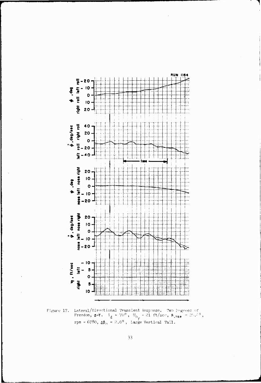
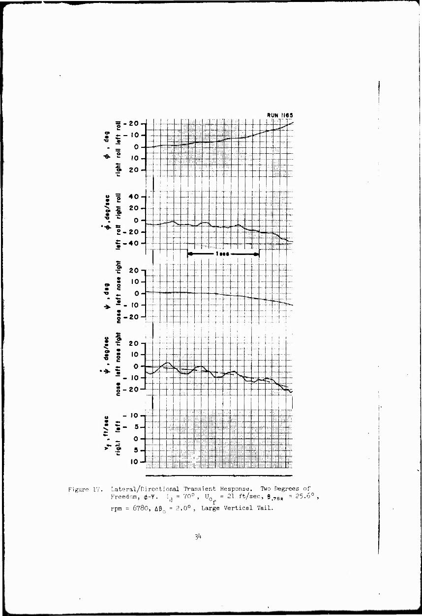
Lateral/Directional Transient Response. Two Degrees of Freedom, 0-Y. i = 70°, U0 = 21 ft/sec, ß.78, = 25.6°, a f
rpm = 6780, APo = 2.0° ,
Large Vertical Tail 33
Lateral Transient Response. IVo Degrees of Freedom, 0-vf.
id = 70°, % = 21 ft/sec, ß.7,, = 25.6°,
rpm = 6780, Ap0 = 2.0° ,
Large Vertical Tail 35
ix
Man

■^
Figure
19
20
21
22
23
2k
25
Page
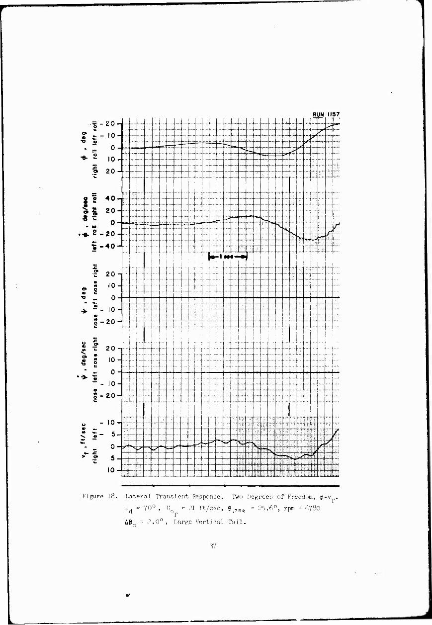
Lateral/Directicnal Transient Response. Three Degrees of Freedom, 0-Y-vf.
id = 70°, U0 = 21 ft/sec, ß.7BR = 25.6°,
rpra = 6780, Aß = 2.0° ,
Large Vertical Tail 38
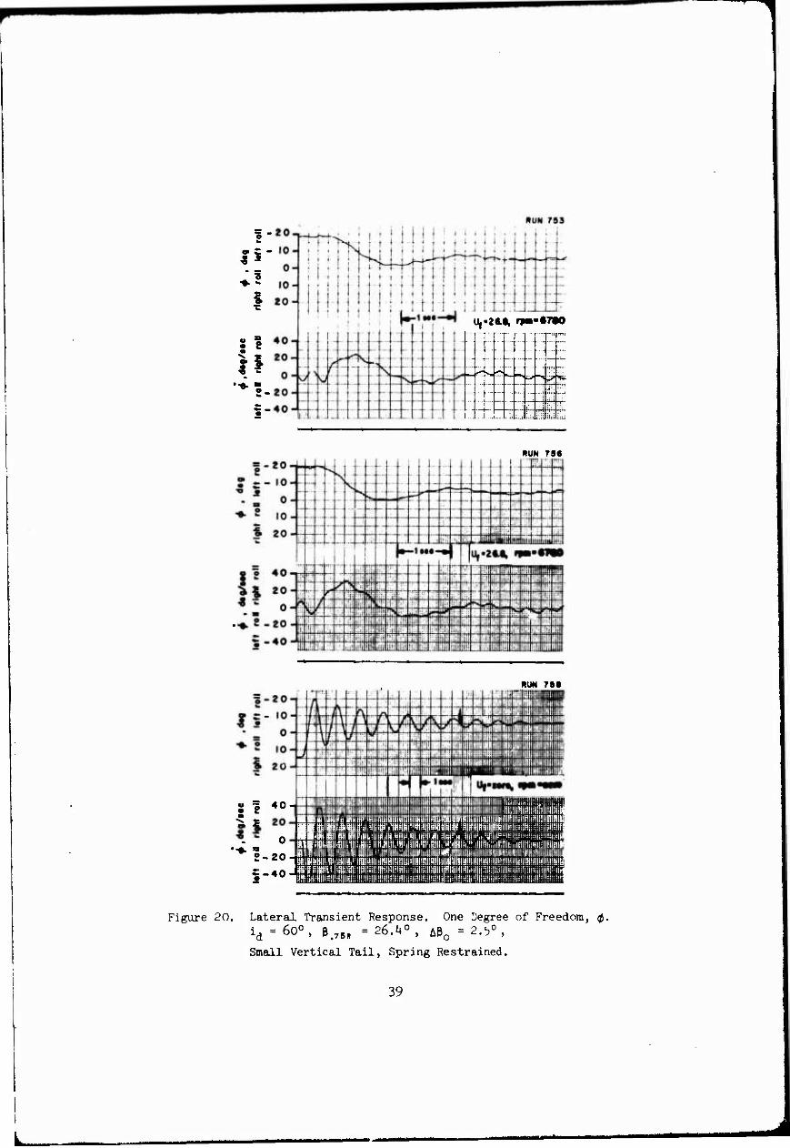
Lateral Transient Response. One Degree of Freedom, 0. id = 600, e.76l, = 26.1+°, Aeo = 2.5°,
Small Vertical Tail, Spring Restrained. 39
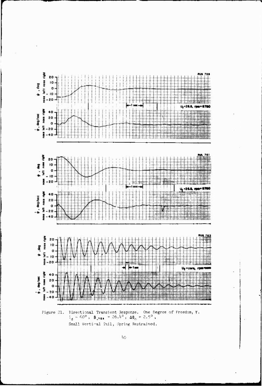
Directional Transient Response. One Degree of Freedom, Y. id = 60°, ß.7BI< = 26.It0, A0O = 2.5° ,
Small Vertical Tail, Spring Restrained ^0
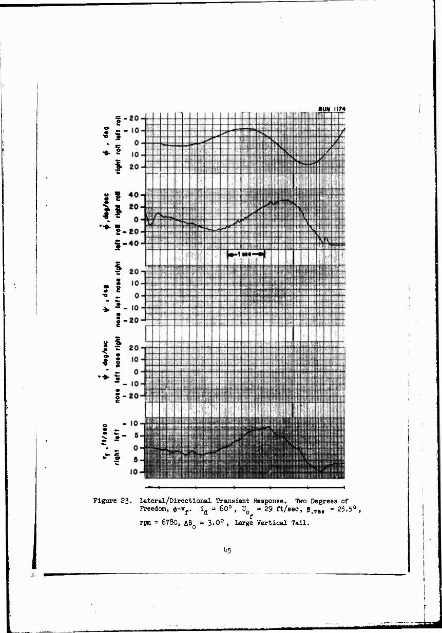
Directional Transient Response. One Degree of Freedom, Y. id = 60°, U0 = 29 ft/sec, ß.7B(, = 25.5°,
rpn = 678O, AP0 = 3.0°,
Large Vertical Tail hi
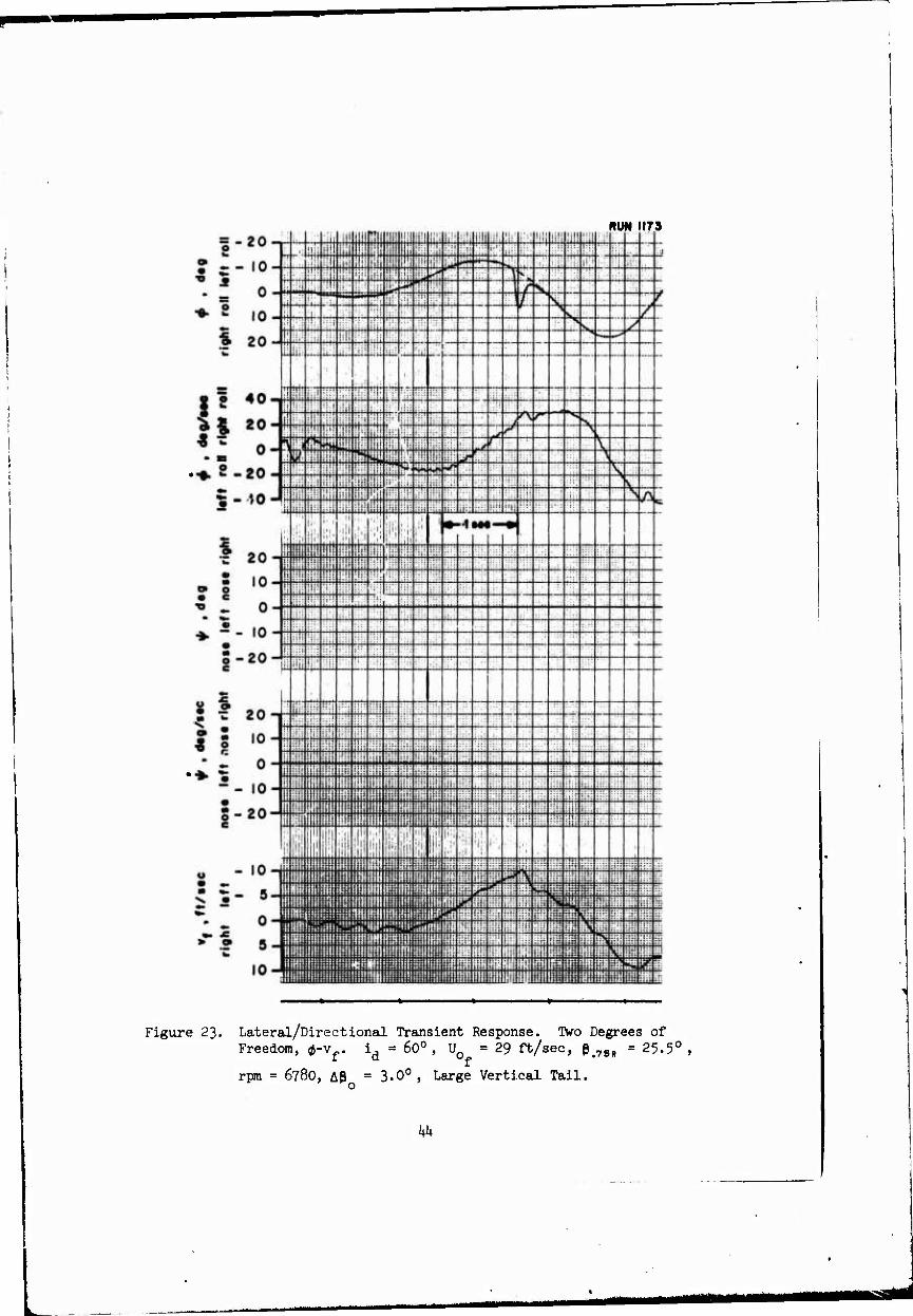
Lateral/Directional Transient Response. IVo Degrees of Freedom, 0-v_.
i = 60° , U0 =29 ft/sec, ß.7M = 25.5° , a f
rpm = 678O, Aßo = 3.0°,
Large Vertical Tail k2
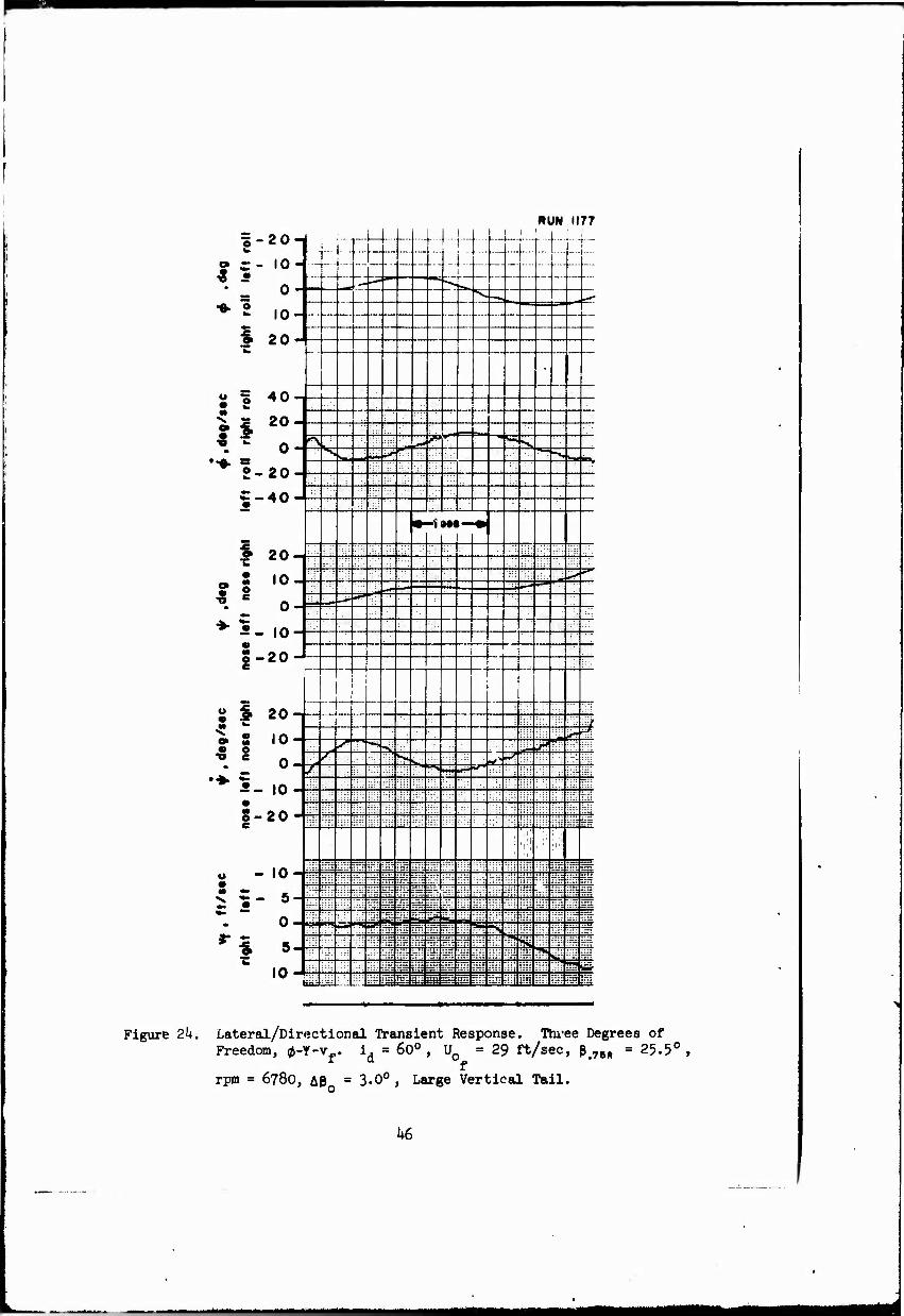
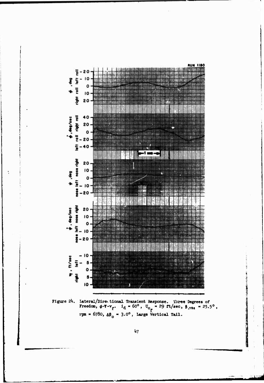
Lateibl/üirectional Transient Response. Three Degrees of Freedom, 0-Y-vf.
id = 60° , U0 =29 ft/sec, p.7M = 25.5° ,
rpm = 678C,. APo = 3.0° Large Vertical Tail k6
Lateral Transient Response. One Degree of Freedom, 0. id = 50°, P.7B1, = 26.U0, Ap0 = - 0.5°,
Small Vertical Tail, Spring Restrained 50

Figure Page
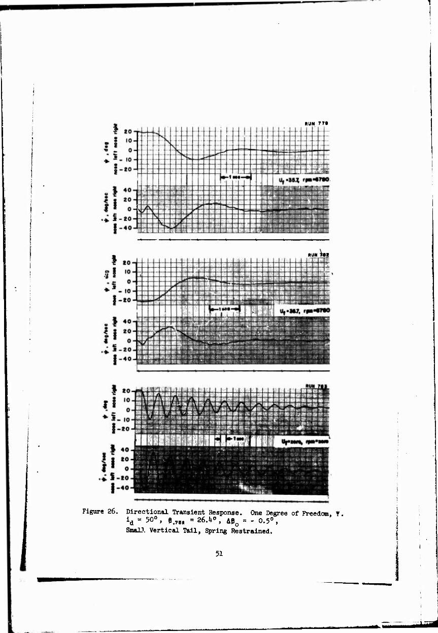
26 Directional Transient Respose. One Degree of Freedom, Y. id = 50°, ß.76, = 26.U0, Aßo = - 0.5°,
Small Vertical Tail, Spring Restrained 51
27 Directional Transient Response. One; Degree of Freedom, ¥. id = 50°, U0 = 38 ft/sec, ß„75)< = 2U.80,
rpm = 678O, Aß = 2.5° ,
Large Vertical Tail 52
28 Lateral/Directional Transient Response. TVo Degrees of Freedom, 0-Y. id = 50°, U0 = 38 ft/sec, p.75(, = 2k.Q0,
rpm = 6780, A0o = 2.5°,
Large Vertical Tail 53
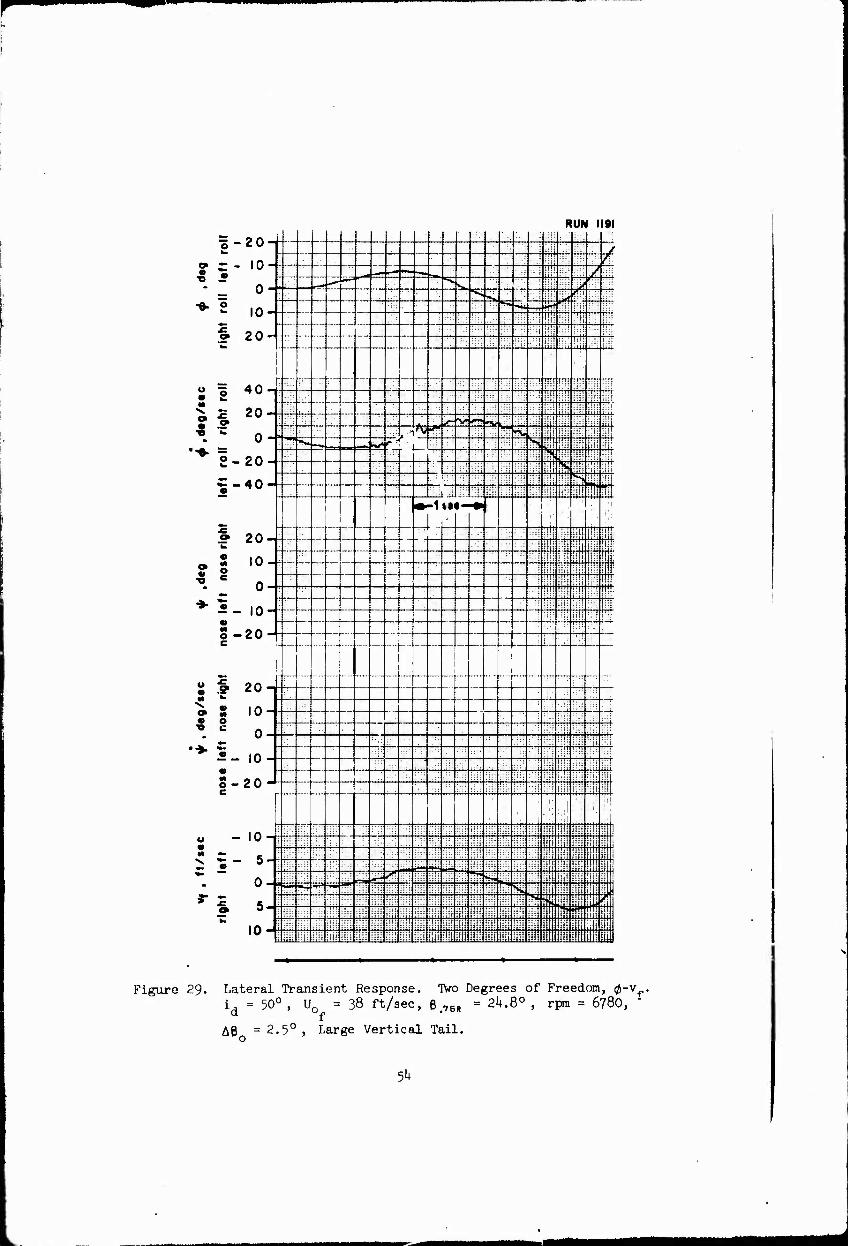
29 Lateral Transient Response. Two Degrees of Freedom, 0-vf,.
id = 50°, U0_ = 38 ft/sec, e.7B, = 2U.80, f
5°
Large Vertical Tail <jh
rpn = 6780, A0O = 2.5 ,
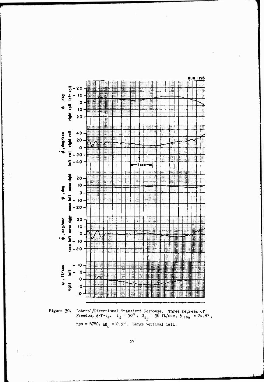
30 Lateral/Directional Transient Response. Three DegreeT of Freedom, 0-1'-v«.
id = 50°, U0 = 38 ft/sec, P,7B„ = 21*.8°, f
o
Large Vertical Tail 56 rpm = 6780, A80 = 2.5°,
31 Model Axes Systems and Variables for Forward Flight Lateral/Directional Tests Sh
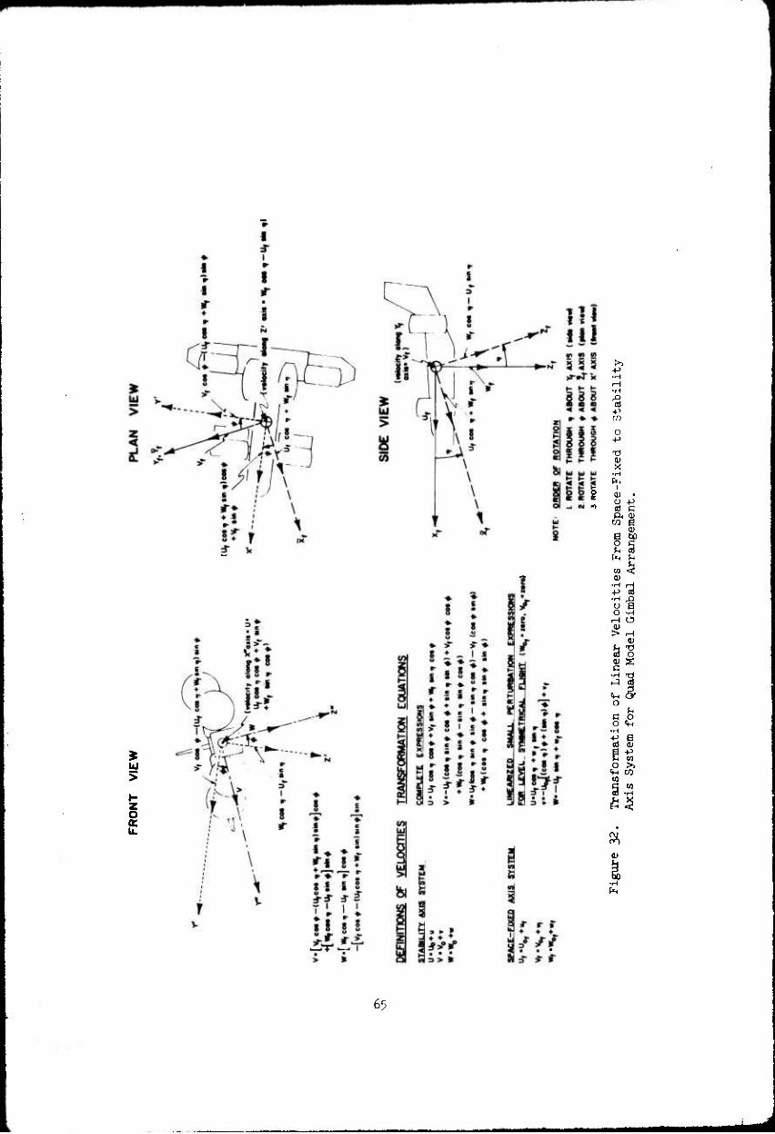
32 Transformation of Linear Velocities From Space- Fixed to Stability Axis System for Quad Model Gimbal Arrangement 63
xi
b
c
eg
d
FS
g
I
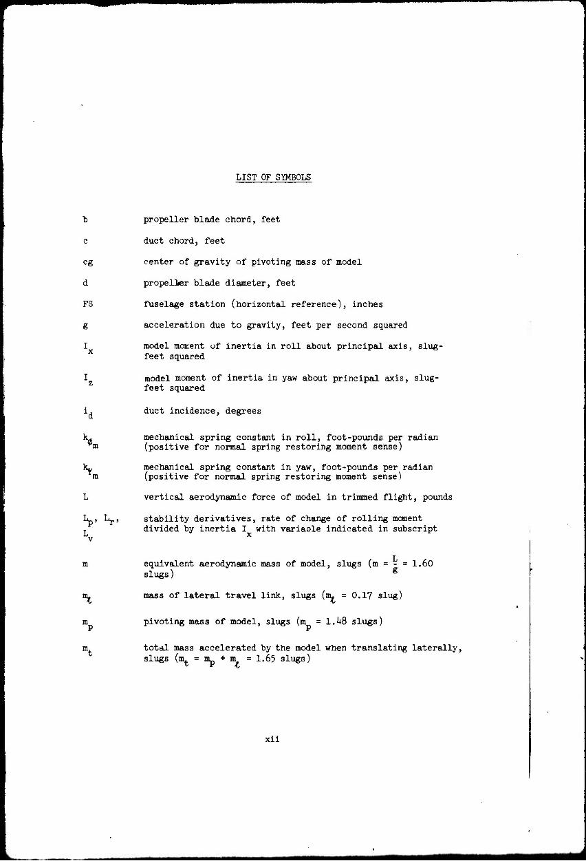
LIST OF SYMBOLS
propeller blade chord, feet
duct chord, feet
center of gravity of pivoting mass of model
propeller blade diameter, feet
fuselage station (horizontal reference), inches
acceleration due to gravity, feet per second squared
model moment of inertia in roll about principal axis, slug- feet squared
model moment of inertia in yaw about principal axis, slug- feet squared
duct incidence, degrees
'm
\ m
V Lr'
mechanical spring constant in roll, foot-pounds per radian (positive for normal spring restoring moment sense)
mechanical spring constant in yaw, foot-pounds per radian (positive for normal spring restoring moment sense)
vertical aerodynamic force of model in trimmed flight, pounds
stability derivatives, rate of change of rolling moment divided by inertia I with variaole indicated in subscript
m
*%
m
HL
equivalent aerodynamic mass of model, slugs (m = - = 1.60 slugs) g
mass of lateral travel link, slugs (m^ = 0.17 slug)
pivoting mass of model, slugs (m =1.48 slugs)
total mass accelerated by the model when translating laterally, slugs (m. = nip + m = I.65 slugs)
xii

m.
r R
ratio of equivalent aerodynamic mass of model to lateral
translating mass (— = 0.970) mt
N , Nr, stability derivatives, rate of change of yawing moment ,, divided by inertia I„ with variable indicated in subscript -v
p model angular velocity in roll about principal axis, radians per second or degrees per second (p = 0)
R propeller blade radius, feet
r distance along propeller radius (measured from axis of rotation), feet; or model angular velocity in yaw about principal axis, radians per second or degrees per second (r = Y cos 0 « Y)
propeller blade radial station
rpm model propeller rotational speed, revolutions per minute
t propeller blade thickness, feet
U aircraft velocity along body-fixed X -axis (principal axis system), feet per second
U0 aircraft initial velocity along X -axis (principal axis), feet per second
U0 aircraft initial horizontal velocity (space-fixed axis * system), feet per second
V- aircraft lateral velocity (space-fixed axis system), feet per second
V0 aircraft initial lateral velocity (space-fixed axis system), f feet per second
v aircraft lateral perturbation velocity along body-fixed Y -axis (principal axis system), feet per second
v aircraft lateral perturbation velocity (space-fixed axis system), feet per second
W model weight, pounds; or aircraft velocity along body-fixed Z -axis (principal axis system), feet per second
xm

w.
\
Wo
WL
aircraft vertical velocity (space-fixed axis system), feet per second
model pivoting weight, pounds (Wp = ^7.5 lb)
aircraft initial vertical velocity (space-fixed axis system), feet per second
aircraft initial velocity along body-fixed Z -axis (principal axis system), feet per second
fuselage water line (vertical reference station), inches
body-fixed longitudinal axis (principal axis system), coincides with model gimbal axis
longitudinal horizontal axis (space-fixed axis system
longitudinal space axis
eg
PIVOT
longitudinal distance of eg from pivot axis, inches
longitudinal position of model pivot axis referenced to FS 0, inches (model scale unless noted)
axial coordinate distance from duct leading edge, inches (full scale)
lateral axis (space-fixed axis system)
lateral space axis
Z
Z.
stability derivative, rate of change of lateral horizontal force divided by mass m with lateral velocity, per second
radial coordinate distance from duct center line, inches (full scale)
body-fixed vertical axis (principal axis system)
vertical axis (space-fixed axis system), aligned with gravity
vertical space axis, coincides with model gimbal axis
eg vertical distance of eg from pivot axis, inches
"1
xiv

m
z vertical position of model pivot axis referenced to WL 0, inches (model scale unless noted)
ß local propeller blade angle, degrees
0, average propeller blade angle on the two front propellers, degrees
PR averse propeller blade angle on the two rear propellers, degrees
ß.75n average propeller blade angle required for vertical force trim (collective pitch),measured at the three-quarter radius and averaged for four propellers, degrees
AL. additional stability derivative due to vertical displacement cg of eg from pivot axis, per foot
ALj additional stability derivative due to mechanical spring in m roll, per second squared
AL^ additional stability derivative due to vertical displacement cg of eg from pivot axis, per second squared
AN. additional stability derivative due to horizontal displacement eg of cg from pivot axis, per foot
AIL additional stability derivative due to mechanical spring in m yaw, per second squared
AP0 longitudinal control required for pitching moment trim (differential collective pitch), degrees or radians
6 elevon deflection, degrees (positive for elevon trailing edge forward with duct at 90 degrees incidence)
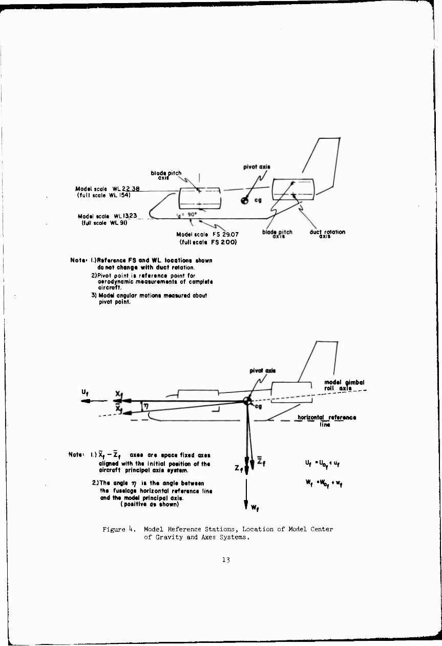
Tj angle between model principal axis and fuselage reference line, degrees (positive for principal axis inclined downward) (6.1 degrees)
X linear scale factor \ = - model length
full-scale length
0 roll angle about model gimbal roll axis, degrees or radians
Y yaw angle about model gimbal yaw axis, degrees or radians
(') differentiation with respect to time
i
jHNfcrf'f-* *■■'■■ M
■■M^MMaaMaBaMHii
r
()'
(")
perturbed locations of axes
vector
xvi
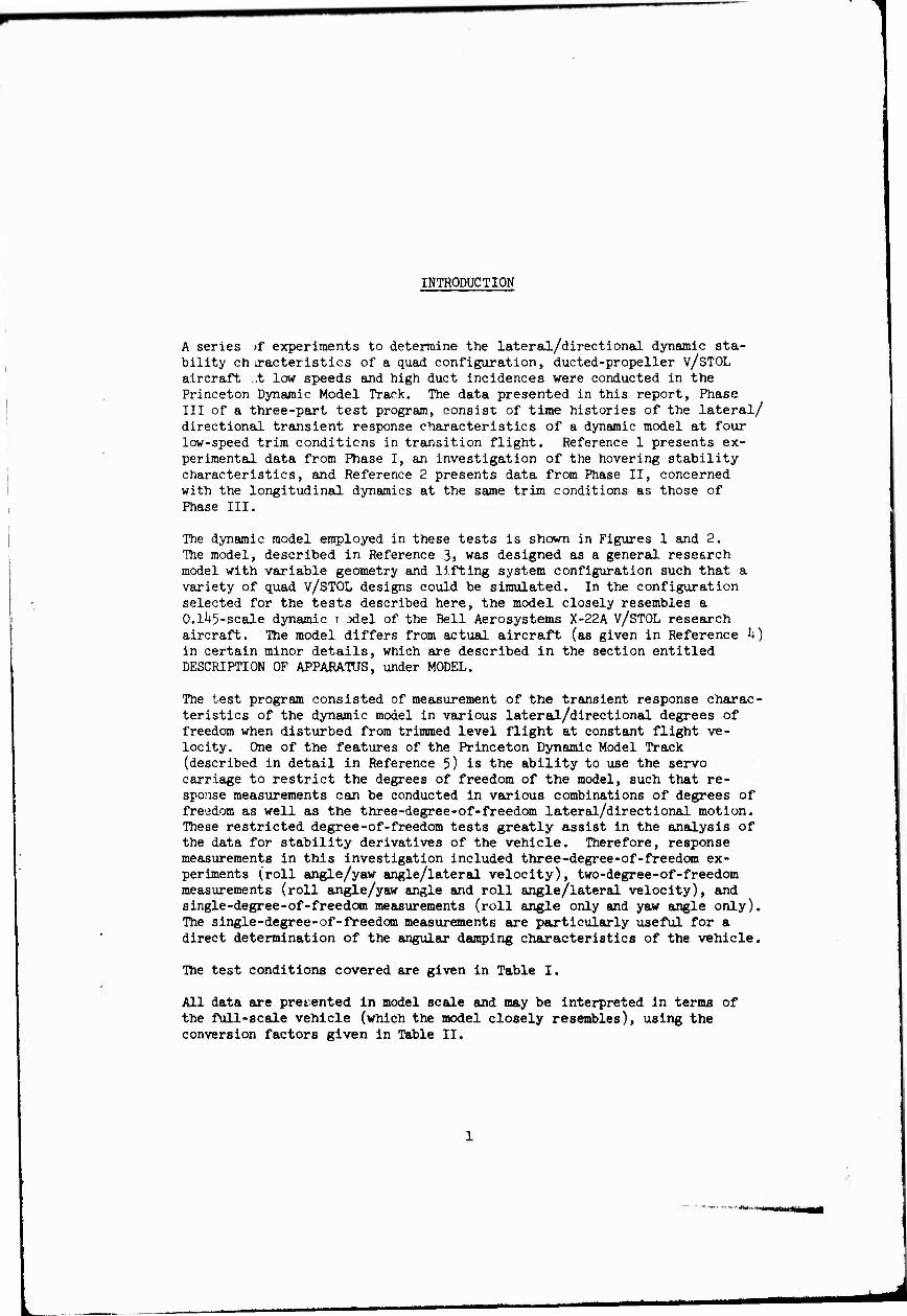
INTRODUCTION
A series )f experiments to determine the lateral/directional dynamic sta- bility ch tracteristics of a quad configuration, ducted-propeller v/STOL aircraft t low speeds and high duct incidences were conducted in the Princeton Dynamic Model Track. The data presented in this report, Phase III of a three-part test program, consist of time histories of the lateral/ directional transient response characteristics of a dynamic model at four low-speed trim conditions in transition flight. Reference 1 presents ex- perimental data from Phase I, an investigation of the hovering stability characteristics, and Reference 2 presents data from Phase II, concerned with the longitudinal dynamics at the same trim conditions as those of Phase III.
The dynamic model employed in these tests is shewn in Figures 1 and 2. The model, described in Reference 3> was designed as a general research model with variable geometry and lifting system configuration such that a variety of quad V/STOL designs could be simulated. In the configuration selected for the tests described here, the model closely resembles a 0.1^5-scale dynamic r xlel of the Bell Aerosystems X-22A V/STOL research aircraft. The model differs from actual aircraft (as given in Reference h) in certain minor details, which are described in the section entitled DESCRIPTION OF APPARATUS, under MODEL.
The test program consisted of measurement of the transient response charac- teristics of the dynamic model in various lateral/directional degrees of freedom when disturbed from trimmed level flight at constant flight ve- locity. One of the features of the Princeton Dynamic Model Track (described in detail in Reference 5) is the ability to use the servo carriage to restrict the degrees of freedom of the model, such that re- sponse measurements can be conducted in various combinations of degrees of freedom as well as the three-degree-of-freedom lateral/directional motion. These restricted degree-of-freedom tests greatly assist in the analysis of the data for stability derivatives of the vehicle. Therefore, response measurements in this investigation included three-degree-of-freedom ex- periments (roll angle/yaw angle/lateral velocity), two-degree-of-freedom measurements (roll angle/yaw angle and roll angle/lateral velocity), and single-degree-of-freedom measurements (roll angle only and yaw angle only). The single-degree-of-freedom measurements are particularly useful for a direct determination of the angular damping characteristics of the vehicle.
The test conditions covered are given in Table I.
All data are presented in model scale and may be interpreted In terms of the full-scale vehicle (which the model closely resembles), using the conversion factors given in Table II.

DESCRIPTION OF APPARATUS
TEST FACILITY
The Princeton University Dynamic Model Track is a facility designed ex- pressly for the study of the dynamic motions of helicopter and v/STOL models at equivalent flight speeds of up to 60 knots (for a one-tenth scale model), Basic components of the facility include a servo-driven carriage riding on a track 750 foet long, located in a building with a cross section of 30 by 30 feet; the carriage has an acceleration potentiell of 0.6g and a maximum speed of ko feet per second. A detailed description of the facixity and the testing techniques employed may be found in Reference 5.
A model can be tttached to the carriage by one of severf" booms,. The mount used to conduct iateral/directional investigation is shown in Figure 1. This mount permits lateral motion of the model in a direction perpendicular to the plane of +he vertical and the carriage velocity vector. The model is supported on a three-axis gimbal system that allows selection of any or all of the three angular degrees of freedom. Lateral relative motion of the model with respect to the model-mount carriage is sensed and used to command this carriage to follow the lateral motioh of the model in a closed-loop fashion. Thus the mass of the mount carriage does not influence the motions of the model. This method of testing may be considered to be similar to dynamic flight testing, but considerably more control over the experiment is possible.
The dynamic tests conducted during this program included one-, two-, and three-degree-of-freedom motion measurements. The transient behavior of the model was dominated in general by an unstable oscillation, so no pre- determined control inputs were used to excite the model motions.
MODEL
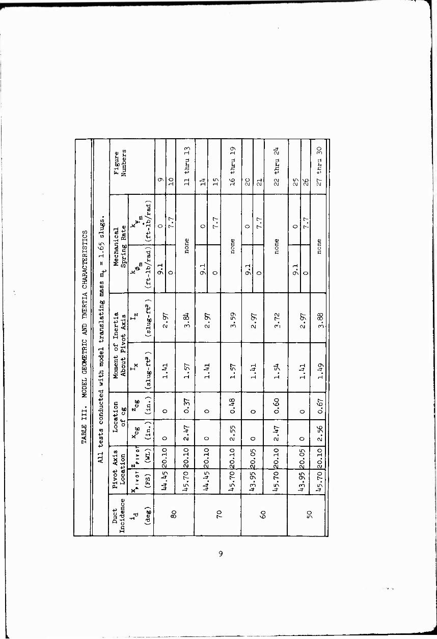
The model is shown in Figure 2, and a three-view drawing is presented in Figure 3- The model's pertinent dimensions and inertia characteristics are listed in Table III, and the model reference stations are defined and compared with full-scale X-22A reference stations in Figure h.
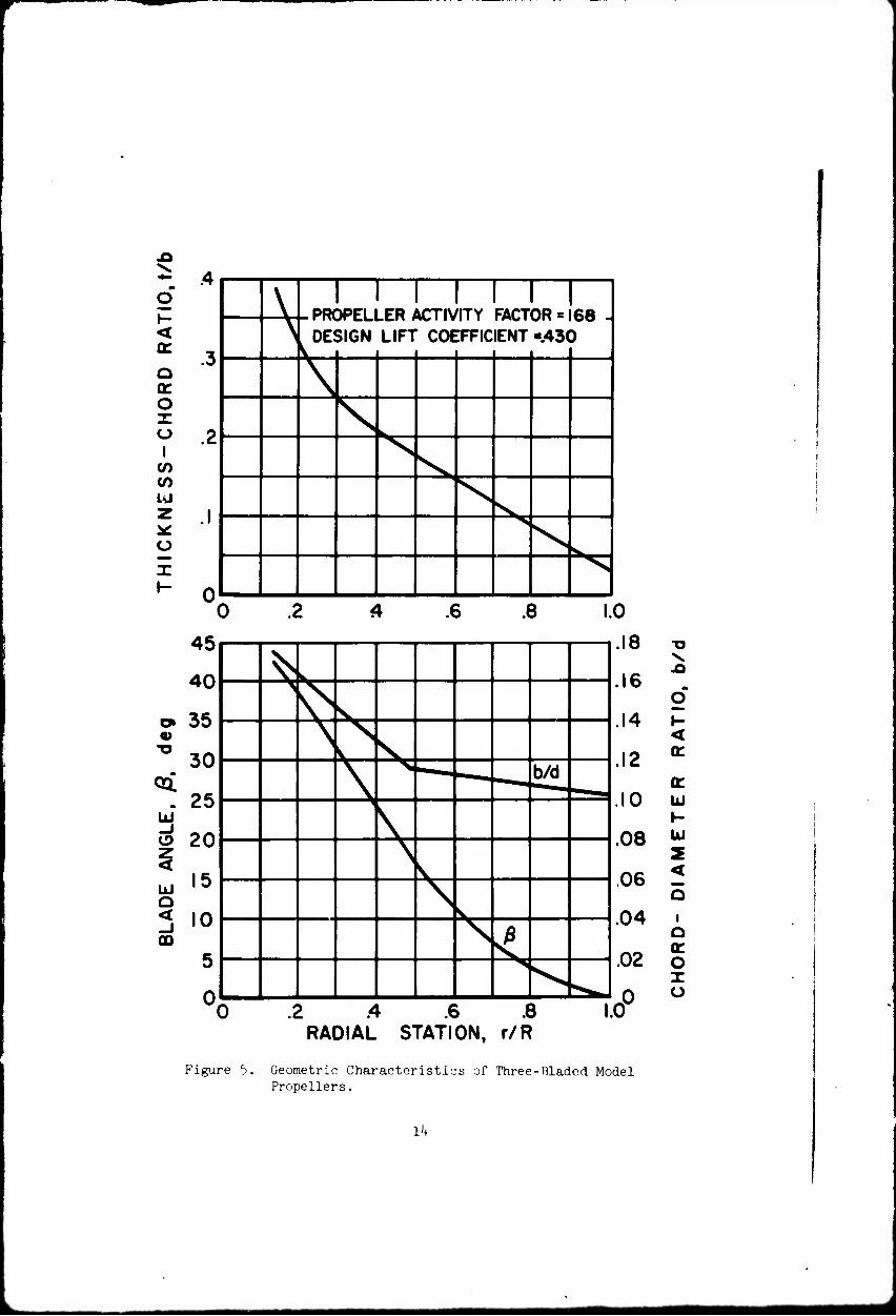
This dynamic model is powered by a 200-volt, 'lOO-cycle, 3-phase electric motor. The motor drives the four ducted propellers through a central transmission and various right-single gearboxes. The aerodynamic shape of the model is obtained through the use of a Fiberglas skin with Styrofoam stiffeners. The propeller blades are made with a plastic foam core and Fiberglas skin. The geometric characteristics of the propeller are shown in Figure 5, and the duct geometry is shown in Figure 6. The duct shape is identical to that of the Bell Aerosystems X-22A aircraft.

Model control positions axe set from a control console on the carriage. The blade pitch singles on each of the four propellers are electrically controllable. Also, the deflection angles of the elevons are electrically controllable. All of these control systems are closed-loop position controls and are used as such in the portions of the experiments involving feedback to alter the transient motions of the model. The dynamic charac- teristics of these feedback loops are such that the time response of the controls is negligible in the frequency range of interest. Although the control servo loops are nonlinear, using polarized relays for power ampli- fication, they can be characterized as having a closed-loop natural frequency of approximately 10 cycles per second with a damping ratio of approximately seven-tenths. The servo gear ratios were selected so that the rate limits arising from the rpn limitations of the control drive motors were equal to, or greater than, scaled rate limits determined from full-scale X-22A values.
This research model differs from the Bell Aerosystems X-22A flight aircraft in the following particulars:
1. The elevon on the model differs from that on the full-scale aircraft. The model elevon has no movable surface forward of the hinge line, and its hinge line is located below the trailing edge of the duct, as shown in Figure 7. While these differences would affect the control effectiveness and the control loads, they would not be expected to have any significant effect on the dynamic motions.
2. I'he duct rotation point is at a different location on the model (8^ percent c) than on the full-scale aircraft (55 percent c).
With the ducts at 90 degrees incidence, the propeller hubs are in the same relative position on the model as on the full-scale aircraft. The center of gravity of the model is higher (by 1.2 percent c) on the model with respect to the propeller hubs than on the full-scale aircraft.
3. As noted in Table I, the vertical tail used on the model for some single-degree-of-freedom experiments was smaller than the scaled X-22A vertical tail. A comparison of the two tail sizes tested is shown in Figure 3-
The only one of these differences that may influence the lateral/ directional stability characteristics is the vertical tail size. 'Riere- fore the single degree of freedom in yaw experiments were done with both tail sizes at all but the lowest speed trim condition. All multiple- degree-of-freedom experiments were performed with the large (scale size) vertical tall.
iaiaaaaHaB|aaBMHaaa

EXPERIMENTAL RESULTS AND DISCUSSION
The experimentally determined trim conditions are shown in Figure 8 as graphs of trim velocity Uf and average propeller pitch P.75R as a function of duct incidence. The elevons were set at zero deflection angle for all tests. All experiments were conducted with the vertical aerodynamic force produced by the model equal to 51.5 pounds in trimmed flight, corresponding to a full-scale vehicle gross weight of 16,700 pounds at sea level. Strain gages were employed on the model mounting system to determine longitudinal force trim. By observing the strain gage readings, the model controls were set such that the vertical aerodynamic force was equal to the desired value of 51.5 pounds and the horizontal aerodynamic force was equal to zero (corresponding to level flight) at all trim conditions investigated. The trim conditions are identical to those of Reference 2. To eliminate extraneous moments from the gimbal mounting system, as were present in the tests described in Reference 6, all tests were conducted with the model free about the pitch axis. The pitch single was maintained at its trim value by attitude sind rate feedback about the pitch axis. The performance of this system was such that the pitch angle may be considered to be constant for all of the data presented here.
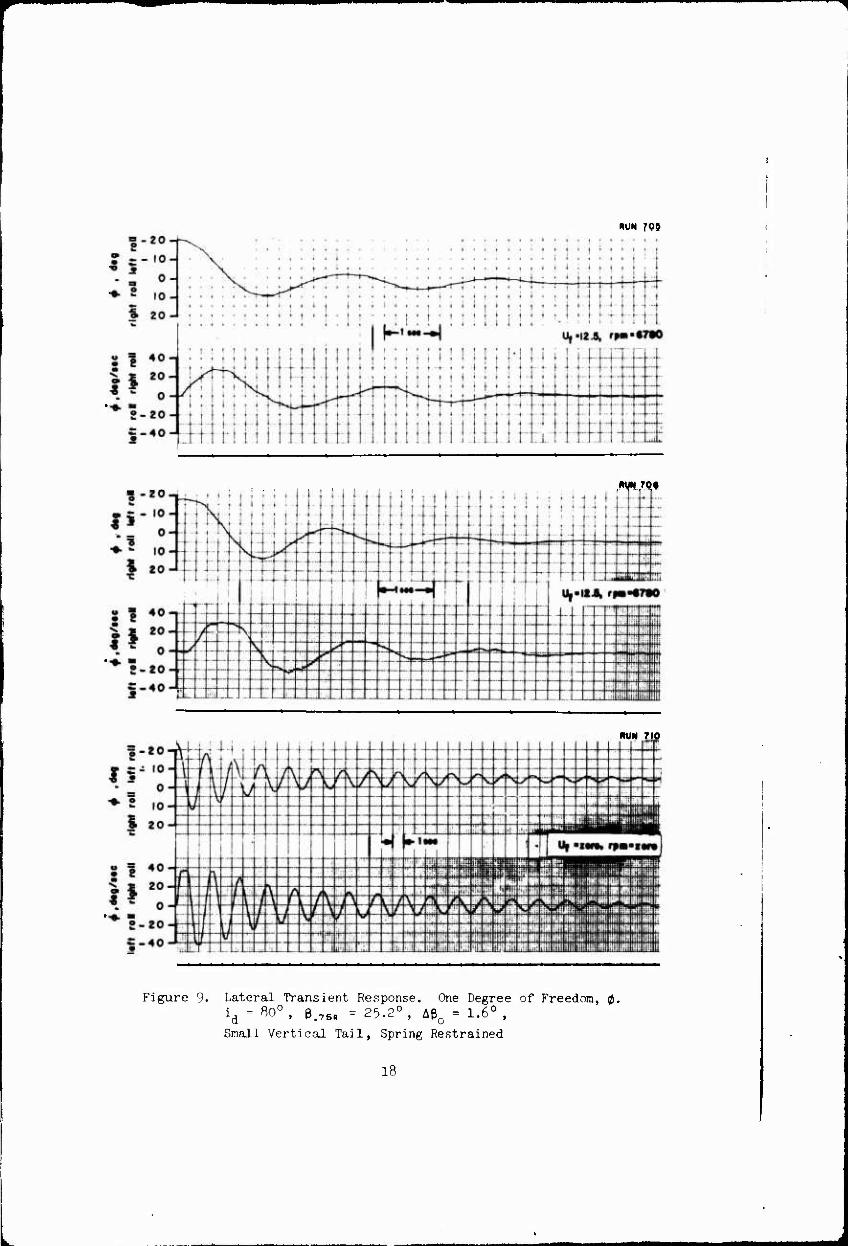
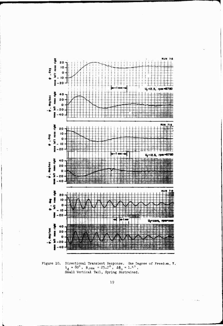
Transient response characteristics are presented about a gimbal axis system, as discussed in the Appendix. Time histories of the lateral/ directional transient responses of the quad configuration V/STOL aircraft model from the level flight trim conditions at four duct incidences (id = 80° 70°, 60 , and 50 ) are presented in Figures 9 through 30. In
most test conditions repeat data runs have been presented to aid in the analysis of the data and to indicate the repeatability of the experiments.
The responses shown include one-, two-, and three-degree-of-freedom time histories as discussed previously. The single-degree-of-freedom responses are presented to permit a direct determination of the angular damping characteristics of the model. These runs are presented in Figures 9 and 10, Ik through l6, 20 through 22, and 25 through 27. For the single- degree-of-freedom tests with the small vertical tail, mechanical springs were added to the model to provide a restoring moment about the model roll and yaw axes, such that the single-degree-of-freedom motions will be oscillatory. In this way the time histories are more readily analyzed for angular damping derivatives. The angular spring constants and the inertia characteristics of the model are given in Table III. Data are presented with the model motor off and the rpm equal to zero so that the mechanical damping of the model mounting system may be determined. This damping, due to friction, is very small compared to the total damping with the model running, but should be subtracted from the damping measured with the model running to determine the aerodynamic damping. For testing convenience the single- and multiple-degree-of-freedom experiments were performed at different pivot axis locations.

In contrast to the data of References 1 and 2, no feedback was used about the roll and yaw axes in these experiments. The lateral/directional motions of the model were dynamically unstable at all test conditions in- vestigated.
All of the transient response time history data presented in Figures 9 through 30 have been conditioned by second-order filters with natural frequencies of 5 Hz and damping ratios of 0.7. However, in some of the model data channels, particularly the rate gyros and linear velocity tachometer, residual signals in the bandwidth of 2 to 10 Hz can still be seen. These signals are due to the flexible modes of mooion of the model and/or gyro support structures or the high frequency transient response of the lateral servo and are not associated with the natural model rigid-body dynamic motions under investigation. In some cases, as for example in Figure 17, where there is a possibility that these spurious signals could be misinterpreted as data, a line has been faired to represent the model's true dynamic motions in the absence of the high frequency signals. In other cases, the transient response of the filters to momentary data loss within the telemetry system has produced data "drop-outs" which have also been faired to avoid misinterpretation.
The model angular velocity initial conditions at release are occasionally masked by the high frequency noise content of the rate gyro signals prior to release. Again, these data should not be interpreted as the rigid-body initial conditions; however, these portions of the time histories were not faired since the first portion of the transient response is of little value for analysis purposes due to the random excitation of the model transient motion. In general, all of the time histories of Figures 9 through 30 start at time zero minus, prior to release. Bind the initial conditions are as indicated on the data record. Exceptions to this are some single-degree-of-freedom data with model rpm equal to zero where time zero has been deleted because the initial excursions are of no value for analysis purposes.
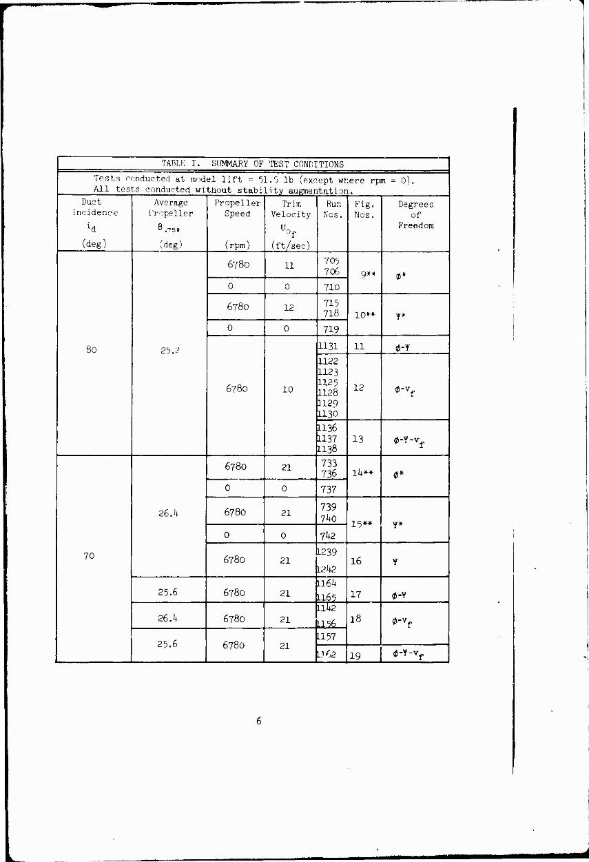
TABLE T. SUMMARY OF TEST CONDITIONS
Tests conducted at model lift = 51.5 lb (except where rpm = 0), All tests conducted without stability augmentation.
Duct Incidence
(deg)
Average Propeller
8.75R
(deg)
Propeller- Speed
(rpm)
Trim Velocity
of
(ft/sec)
Run Nos.
Fig. Nos.
Degrees of
Freedom
80 25.2
6780 11 705 706 g** a*
0 0 710
6780 12 715 718 10** Y*
0 0 719
6780 10
1131 11 0-Y
1122 1123 1125 1128 1129 1130
12 0-Vf
LI 36 L137 L138
13 0-y-vf
70
2G.h
678O 21 733 736 Ik** $*
0 0 737
6780 21 739 7^0
15** Y* 0 0 7^2
6780 21 1239
I2h2 16 Y
25.6 6780 21 ll6h
L165 17 0-Y
26.f+ 6780 21 Lite
1156 18 0-vf
25.6 6780 21 1157
L.l 62 19 0-Y-vf

TABLE T - Continued
Tests conducted at model lift = 51,5 lb (except where rpm = 0). All tests conducted without stability augmentation.
Duct Incidence
(deg)
Average Propeller
ß.75R
(deg)
Propeller Speed
(rpm)
Trim Velo( ity
% (ft/sec)
Run Nos.
Fig. Nos.
Degrees of
Freedom
60
26.h
6780 27 753 756
20*-* 0*
0 0 758
6780 27 759 761 21** Y*
0 0 763
6780 27 122h 22 *
25.5 6780 29
1171 1172 1173 117U
23 0-vf
1177 1180
1181
1181*
2h «5-Y-vf
50
26.h
6780 36 773
775 25 0*
0 0 778
6780 36 779
782 26** Y*
0 0 783
6780 36 1206 1208 27 f
2h.8 6780 38
1199 28 0-Y
1191 1192
29 0-vf
1193
1195 30 0-Y-vf
*Mechanical spring in place.
**Small vertical tail.
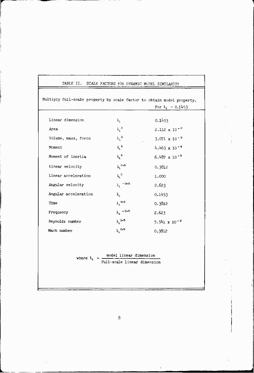
TABLE II. SCALE FACTORS FOR DYNAMIC MODEL SIMILARITY
1 Multiply full-scale property by scale factor to obtain model property.
For XL = O.li+53
Linear dimension h 0.1^53
Area K2 2.112 x 10"2
Volume, mass, force K3 3.071 x lO-3
Moment K* h.h63 x 10"4
Moment of inertia KB 6.^87 x 10"5
Linear velocity \L0-5 0.3812
Linear acceleration xL0
1.000
Angular velocity xL -0-6 2.623
Angular acceleration h 0.1J453
Time 1 0.5 0.3812
Frequency xL -0-5 2.623
Reynolds number x,1-6 5.5^1 x 10" 2
1 Mach number xL0-5
0.3812
j where XL = model linear dimension
full- scale linear dimension
m Ch -* o 2 "
1 H CM no
^1 p p P p
ON o rH J- ir\ VD o H CM LA VD f- H rH H i-l rH CM CM CM CM CM CM
i u •
03 ^B.5 t^ • f- t-
rH .-i ^
Jrf H o 1>- O t^ o t^ o C^ 1
5 M QJ ai m (U
II C O
c G
c a 5
o ^-^ M • i C c c c
II m
rH H rH
1 ^ ^ H 1
P
a\ o ON O ON O ON o £C CO <M o a> s
^ 1
H bO '"*■"''
a •S H 1
(0
p Id •H.S & 5 &; as fe ^ S^ §
H p c
M o ^5
• • • • • •
1 (0
^1
CM oo CM en CM* O'l CM on
y -p
S 0) o5: ^_
1 1 1^
- 1J H t^ H t-- H ^t rH ON
g ß M 1 J- • -d" iA • • LA • J- -4- •
■P H H rH H H H rH rH >-5 •H H W > n Q Q
■P X
to o c
N -H
t- 00 O C-
M M 1 1? O
• o O d O
VD • O O
VO • o
M o «5, ü 1° ^-^
1 w ?P c IA ITN ^ )R
§ ■p w V p
x0 Ci O CM o CM o CM* o CM
m o '"^ O O o O IA O LA O •H n ^•2 «. —'
H
d • O d
H
d o • o
rH • O
o • o
H • O
o o > o
N CM CM CM CM CM CM CM CM ►- ITv O LPv O IA O IA O o ' "* J- f- -3- C- OS C- OS t-
s^ -j • •
-3- •
IA •
en •
IA •
CO IA x' J- -J- -4■ -J- -a- J- J- J-
(U o
O o c ) c ) 00 c- Vi 3 Lf N
5
c. o -o <v +J t; rt o
H ^ OJ -P
T) ni O ^H S cd
M) ft C <
•H ^ M O C ü -H CO -P
x e-« o cd CJ
0) ^
o ^^ •H O
P 9. o
•H
o ^\ a) d Ü fn C (D
•H +J
^5
0)
10

0)
O
o •H
Q
o •H
cd
■H
c O U
-0 a)
o w
I in
OJ
•H
11

o S
c o •H
<t-l ß o o
c s 0)
c 5
12
blod« Ditch axis
Modal scale WL 2.iLM (full scale WLI54)
Model scale WL 12123 (full scale WL 91)
Model scale FS 29.07 (full scale FS200)
duct rotation axis
Not«1 ^Reference FS and WL locations shown do not ehang« with duct rotation.
2}Pivot point is reference point for aerodynamic measurements of complete aircraft.
3} Model angular motions measured about pivot point.
Not«1 l.)Xf-Zf axes are space fixed axes aligned with the initial position of the aircraft principal axis system.
ZjThe angle 17 is the angle between the fusslage horizontal reference line and the modal principal axle,
(positive oe shown)
modal oimbal roll axis __
Y
horizontal referanca line "
Uf "V-f
♦wf
Figure h. Model Reference Stations, Location of Model Center of Gravity and Axes Systems.
13
^ .4
<
o a: o x o
I V) V) iy
o X I-
\ 1 1 1 1
PRAPn 1 FR ATTIVITY i
PArTOR r 68 . \ DE! SIGN LIFT • cot :FFIC IENT ■.43( )
\
\
N X \ s. *%
^S s V
UJ -j o
UJ Q <
CD
45
40
35
30
25
20
15
10
4 .8
0 .2 A .6 .8 RADIAL STATION, r/R
1.0
^ t.
>
^ \B
\ V \
>> — b/d
^_
\
\ v \
V \ <
^v ^
.18
.16
.14
.12
.10
.08
.04
.02
1.0
■o
<
u
LJ
.06 ^ <
I Q QC O X Ü
Figure cy. Geometric Characteristics of Three-Bladed Model Propellers.
Ik
mm

*- y
RADIUS
STRAIGHT LINE
ALL DIMENSIONS ON ABOVE DRAWING IN INCHES (MODEL SCALE)
|*-22A DUCT OOTCTT OROlNATESt m
irsr 12
33Z m 14.700 17.750 I2J
i 29.400
iP ^m
•ULL SCALE)
47.625 46.695
^
S2S SHH 50.763
?Q??2 50.164 49.649
^Mifi_ ^^- :5^g:
Figure 6. Geometric Characteristics of Scaled Model Ducts.
15

is
11 Sw ox
a <u
■p CO
to
0)
o
o
ß O
•rl
cd V o
0) o c D
0) «
CO o
(U
o •H
i
4>
•H
16

1
8 I
O o UJ >
45
40
3S
30
29
20
19
A
= 10
A
I 0
^
•VNJ 40 90 60 70 DUCT INCIDENCE, idtdta
27
a. a: 3
26
29
g a; * a.« hi? <oa. OS
241
2
22
^SJ
a
e. i
0
70 40 90 60 DUCT INCIDENCE, y, dig
80 90
&.
80 90
Figure 8. Experimental Data, Model Trim Conditions, Model Lift = 51.5 lb, rpm = 6780.
17
RUN 795
im jo*
RUN no
Figure 9. Lateral Transient Response. One Degree of Freedom, 0, id = «0°, B>75R = 25.2°, Aeo = 1.6°,
Snail Vertical Tail, Spring Restrained
18
RUN 7IS
RUN 7lt
Figure 10. Directional Transient Response. One Degree of Freed-jm, f. id = 80°, B.78R = 25.2°, Aß0 = 1.^°, Small Vertical Tail, Spring Restrained.
19
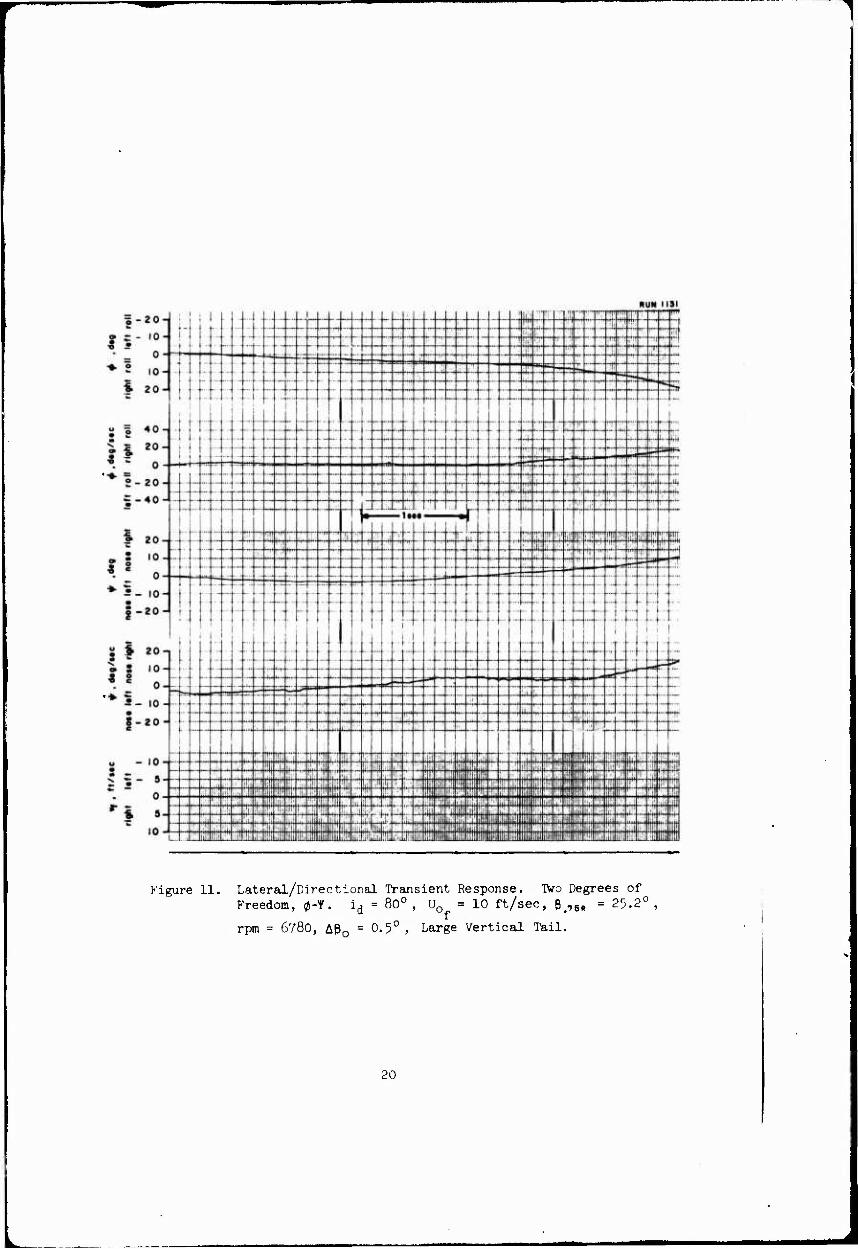
Figure 11. Lateral/Directional Transient Response. TWo Degrees of Freedom, 0-Y. id = 80°, U0 = 10 ft/sec, B.75« = 25.2°,
rpm = 6780, A0O = 0.5° , Large Vertical Tail.
20

.. _.. —
— __ .... .._ .... .... IT ....
Hi JN (22
S-£U- — ~ -
- _ o-
;ii;
.... ^ — ^ /
^^ "! —
~ .... — ... ***-" is» **;
■«^
... .... ... .... ■^
t.
■«• 2 ,o.
• 20-
»v« ..
....
/r>
- — ....
.._
\ ■;- s
rr^i
.... I
« | 401
| | 20- .. „.
« ^ 0- trr J-' —
— ....
r> ■^ X
N s, ****■ •**•' "'
.... 2-20-
= -40^ ::
-.-i -:-
—
, — --
■«1 .... ....
;~
-1 M »-
:~ pr:
.4
1 20n - :
- . I
.-. ....
: IO- — — ! i ! — — 1
^ c 0 0 - r ;
*5-io- i: —
-4—■ —
S-20 J XJ
k.—
— — ...—
— —
i
s 1 201 ....
-- —.
—. 4f w s io-
' § 0-
.... -- — -- -f —i ^ -- ....:.
••- — .... III!
** ?- 10- ■
.... — — ™ ~ 8-20-
:
— ■
.„. .... ■mr :r- .... ~ ::;: ' O — 10 -
■| ::
:■■. ir ■■ ■ i:;.: :::i :
• i K ■::
*-~?
i •" '- r!: ■:■
;ii iili i|ti i ' |
"^ ~ 0 ; ii** t^T > 1"" 4« ■iiij ä •!l ttii Hi1 \ • u - +ff
' ■ .i i '
•:il m l\ i:il :i:t i-ii '• ja! '* 5
.;;: ''! ■;-. rt" '■i: — , .' ill! i$ d !!i: ,
-I: ::'! ftn ;:i ■.;■
i1. !;!: !t!{ m Wiim A
1A —T :::i ir i'i 'iii i;;i !' !: i rft ;!:! :;i; ■!:; m It! iji i l i i: |
10 •* il.. ,-i (jit il; !!ji iii 'i! iii I-1
'!'• :. III 1 ill i iiiii
Figure 12. Lateral/Directional Transient Response. Two Degrees of Freedom, (J-v . i, = 80° , Uo =10 ft/sec, g,
rpm = 678O, Aß = 0.5°, Large Vertical Tail.
7BH 35.2°
21

w
RUN 1123
- - 20-n | i i } -t-j-t
Figure IP. Lateral/Directional Transient Response. Two Degrees of Freedom, (J-v„. i , = 80° , II = 10 ft/sec, p 7BR = 25.2° ,
rpm ■780, Aß = 0.5° , Large "ertical Tail,

i-20-J RUN 1129
: :Mi-Tin!;;;;;; ü;
Figure 12. Lateral/Directional Transient Response. Two Degrees of Freedom, 0-v . id = 80° , U0 = 10 ft/sec, B<7B = 25.2° ,
rpm = 6780, A0O = 0.5° , Large Vertical Tall,
23
.♦UN 1128
1-20-1 — ....
rm ~- m _ / r
— ....
• _ o- ., •_
^^ _:_ — s
/ — —
♦ 2 10- ^ •-«. , ,'
— .... —
•—
....
..„ ...
'" ~^ mm' .... —
% 20-1 .... —
•- .... .... ....
..„
U = Ad mm 1
1 frti"
m S ^0
ft 20- «^
.... :.. -- — f- .... .... — —- — .... .... ....
-— .... .... '. " 0- ^ jss *= rr* •#
"w. N,
N ^ 2-20- ^
— -f- ^, ^-4oJ •v, "•m
—• -i* M- •i
Hi: :
■£. on !! " •c '•v'
...
' c 0-
. _ .... -- :- --- 4^; .... — — ....
o - III! "" ■ -- :- — *-5.io- — ....
— ■
— .__ .._.. -r -_■
0-20^ e
...
... i
—
™i ■
s 1 201 , — -
— — -- — — o s io-
• o ■- — .... .
^ g 0- ::■
■*" • 10- It-'
mm — l\J — •; ■ .': '.'■. .;
i;:: :: 5 - Z0 -' e ■
■ . I'I; Ml1 :!
!•! hij iili !ili !!ji P ii:! ;■■ ! (!:! U — IU " ii; .::! }ii! j,.; ,, ! iili :: ■
ilii !! '■ I!;:
^ C S- ; ::: •! '■',',] ii H v "5- 5- !::i
i :l!l i!,,* Kil : :;;- H j'",' •{■■
0- iüf ■Mi "7 ■an ** :- i | 'rT; •W!
hi; i:i: ;|l M? ^ ^m. ;. Ii ii.; i
^ * 5- : ijij !$ 41
1 1 111: i:i: O» 3" :::: |iji:i : .: I rS s jii y i liii «i nj ii
Irt - i ii i1!! t i ;;;t
Iw "1 ■■■! ilii i llli liii Ill mil l li 111 11! i
Figure 12. Lateral/Directional Transient Response. Two Degrees of Freedom, 0-v . i = 80° , U0 = 10 ft/sec, e#75H = 25.2°,
rpm = 678O, Aß = 0.5° , Large Vertical Tail.
2h
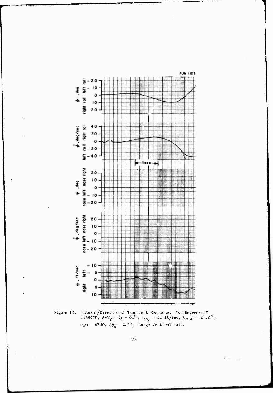
Figure 12. Lateral/Directional Transient Response. Two Degrees of Freedom, 0-v , id = 80° , U0 =10 ft/sec, e#75), = 2^.2°
rpm = 6780, AP0 = 0.5° , Large Vertical Tail.
L

l-zo-.
Figure 12, Lateral/Directional Transient Response. TVo Decrees of Freedom, 0-vf. i^ = 80 , U0 =10 ft/sec, e>7B), = 25.2°,
rpm = w'Bo, AB0 = 0.';° , Large Vertical Tail.
2^

RUN 1136
»•s
- 10
- 5
0
5
iiBHISiiüliliHiiilii ililllflii yiiliiOliBiiliruili liliitlHIIHiiiliiilHi^iiyiliu! itii^iliiinHliii^iliyiiiiihJ! Hiülinfiililil niiiJiHülliillmlHiilill iiiiliHIIiJ
::i:: ::J!;;ffitt^nii|timi!WiiHH»lWliti»Htiittt)#WulT;Htttiim»liUnmni»t<H4ltf:li!ll
yyiHiUHIP ilil BliiH|ill!P*;r< Hin {ffiliöHini ill; ii üiüHüili !Hil HfflSB lüiPHHi!!:'!!:::; airföl Biil^iSyilffi III li=S^ii !i iiüli III! Hli! yy«ateüiyiij ai liinyn liiii^iiiiiiHiiüiniyüiiHyüii;«üufj mm] mmmm® 111 liiliilU ifiLltil lilli llililiyiliüHü! illlilülli üiünliillllnii!!
Figure 13. Lateral/Directional Transient Response. Three Degrees of Freedom, #-T-v . id = 80° , U0 = 10 ft/sec, Bi7BR = 25.2°
rpm = 6780, AP = 0.5° , Large Vertical Tail.
27
RUN 1137
Figure-13. Lateral/Directional Transient Response. Three Degree.-, of Freedom, (i-Y-v . i^ 8oc = 10 ft/sec, 0#75,
rpm = 6780, Aeo = 0.5° , f^arge Vertical Tail,
PR
■s •
-0. o
•c
■8 «
o -
» s • o
8-
r s
■ | ,; ; 1 l I l i I I I
-^
—
—
R UN 1138
zo- ! I r T j -
-
--
, -- .... iO-
r ... — ...r
^ / I T
i-f- —
... — -- ./ o - - - ^
10- ' T
■■i--t-t" ~ —
--- .... z: .._
~ 20-
40-i
— -- ....
.... ....
• ■
....
l ......
-—i- - -4-
:
20-
—. —
"-
T
— _. S*1 -E ^T! ^TJ r»^ •s ....
0-
.^1.... — _.._
•N. — — --
20- .... —
"v ■s
• -
.... — -- ~ — V ^
40- -- V
-1 M "*
20-r
.r..., ..T...... ; i i
i
— ~~
— .._ -„,
- '"' -~ —■
10- —, —
.:■:
fs ^i ^ — — -- o - "" — _ — ....
— •**^
J
10-
20-
20-
10-
!
....
I i —
1 i
-1
- f- —1 ■-
... ...
ss» ̂ -•w »*
....
z i
2 w- 0-- -^ _..
1 fS -- ■r
^ ^ — 10 - - ■-
-- — -- .... 20 ^"
- —
— ---
i.i-
— . «_ m ™. T — __
10- !.:. i-:i
M ;;.. ■"■ ■' 0 -
S 7S y FSi 'S s. ■^ Si
i ._. i o- = :^ — ̂ **
— s# *m ■
::: ■:: ■ if . w "-• • ■ . ...:
t/\ '.;■: : :: :::: : jj:: ■;;!
10 - - l'r till iiii .1 iiii ;;,i i-ii iiii
Figure 13. Lateral/Directional Transient Response. Three Degrees of Freedom, 0-Y-vf. id = 80° , U0 = 10 ft/sec, e#7B(, = 25.2°
rpm = 6780, AB = 0.5°, Large Vertical Tail.
2>>

RUN 793
RUN 736 3 . O • 20
9 ^ a • 10 W •
0 - O
■6- »- 10 «. 9 20 w
I1 40
** 20 < ? 0
• CS
♦ 2- -20
•a-40-J
RUN 737
Figure 1U. Lateral Transient Response. One Degree of Freedom, (J. ^ = ^o0. B.75R = 26.U", Ae0 = 5.0°, Small Vertical Tail, Spring Restrained.
30
.
RUN 79t
RUN 740
% 40
20
0
••■ - • -20 • I" -40
twPKMiwmjmMiiiw
|i!Hlilllll!IH!ii«llil!!tlffll«tPI«i||!i!l|H|!Dtl(|ü.! hl flDHIIiii lÜitüyilHItiJnillil HIHIU ültilllWittUlHlfllllllii li ,' iv '
•■■•ill«««™M^ i', ••,-•.',»,<'■
RUN 74f ■iiiii j HjjiüHiHfiiiiimt iHillliiifll.li
IWIHlülillitUlilillültiliiüiWiUii iit!r{[!{^j|ni{{||inniji(jji-rni{i!!;itiij ini»IIWn!1i!i!)'i!Hiiiffl»Wli|l!l!l
il'iilNT:!!! liiilliii!
Figure 15. Directional Transient Response. One Degree of Freedom, f, id = 700' ß.'BR = 26.1+°, ARo = 5.0°,
Small Vertical Tail, Spring Restrained.
31

RUN 123»
£ •c
RUN 1242
7 ^
I« »-
? i
c o c
Figure 16. Lateral/Direotional Transient R(._ponse. One Degree of Freedom, y. 70° , U0 = 2.1 ft/sec, p 75R = ^.6° ,
rpm = 6780, A0 = 2.0°, Large Verti-'al Tai
32
|-20-i -- 1 1 1 RUN
M 1 1 1 1 1 1 i T 1164
—- — .... --
'
Is-10" r-'
— ._ .... ^3 —
i=» M ac _-. —■ .... — .... —■" -:r-:
0- -— —
— — „_
" - _-- .... — ——
— —
--r
rrT-
♦ 2 ,0-
% 20-J
~"~ _ — "-- .... ....
....
....
o 1 401
|i 20- '. " 0-
..... - r ■ • "■ i-t- j- i -
--j ■ ■
4x
1
I ■ ;
....j...
. .4...
!
.... -■-
.... .. .
....
„ ■—
*" 2-20-
= --oJ 1 i T
^H ... -ft- _;. ....
.... V- •< Nr'
I...]. I.........;I.. ILL I
^s«
^S
i—..
1 20- ... ....
• -- —
-- .... —
— .... «a- — — ....
«i,
- -j—■ 1 ..
.._ .... ■cu.
— — ... ... 0 -
1
1 (-- i-
....
...
-i - ■4- —i- -
... ..
I...
.... ♦S-,0-
i-"J
• 1 201
-- ::: ....
...
....
.... —
...
—- ....
■
....
....
..
—
....
... ....
—
I 8 ,0- ' c 0- ^i-i-
....
5 -!■■-
1....
1 1 t
...
....... er. *i-io-
8-20- c
u - 10-
1 5" 5"
— ...
... .... ....
...
■5 5
O - i !
'1 5- 10 -
:... I"*
.... ! ....... .... .... .... ....
—
.... xX .... .... ...: -r
:~
.... -•:
...t.;:. .. . .;
F'iguru 17. Lateral/Directional Transient Response. Two Degrees of Freedom, (J-Y. i = 70°, U0 - 21 ft/sec, B
rpm - 678O, APn = 2.0° , Large Vertical Tail.
.761» 01, ,',0
33
"-1
= _ 9n _1 1 1.
-^
... Rl m ii 85
o *•" .:. — — -•• n- — <- ? ".
K?
? - - 10-
—
~ „-. „^ mm in- «Bftrr ■z.
- I o- ...
—
-■
. •*T* — .... ""' Trr-
— ....
— ■ ;
— .... —
"*■
■«■ 2 lo- .... ....
r.:: •4 ;:;. —T* ;... .... -"
w 20 J
—
-f*
V«.
-
.... -
—
....
S:
.... « | 40-
'. " 0-
—
S
-■
"t-
S- 20 - — X
^r ^
C-40- »rrr mr rrrf TiTT mr i-^
' ■■,.
II .
—
. -. __
■ --
1 a»
•? 20-, -— ,-- ....
"^
o o ... .... -• r- ... .... ...
^ : o- ^5-io-
S-20- e
1 1 '<>-
1
...
....
... — ...
- --
-
...
■ ■
.. . . ..
"' ~
.... .... ... -
^r 7 ^
.-
■-
t S
-
....
i
A :.;.
■~-
" - 0 - ^
.-- r^ ■v,
MU
^ 'S -_ |0- •-
A
....
-:- — : '- Is >-c "-r \.
• Ort
—
...: ^ ~
:
O - cv ..;. "V
« - io-j ....
.... ..;. .... 1 — ....
i I .. -- —; -- ^ 5- 5- -4 -TT
.... ;...
*". o- ....
■
* » 5- .... .... .... .... . ::l :
— -T -4 -r _. --;- -~ — -i .... .... ..;
' .': ' ■^ :■
Figure 17. Lateral/Directional Transient Response. Two Degrees of Freedom, (J-Y. i(j = Y00 , U0 = 21 ft/sec, 0>75R = 25.6°,
rpm = 678O, A0 = 2,0° , Large Vertical Tail.
3^

♦ 2
I 8
• c
O C
« g
o e
> 9
7 n -4 if-!; ::.:i .]:': tn
RUN II 42
'ii: ;::i ::]
_ :;: ;:: ■
!:i if!! ■::■ ::-i :li
i n _ i; i "i1 !j:i ^- r" ?*s «>, !:| i| ih iH
:;•; i:!: :::. '& fi" N ; : jj rii iff 1
rt !!:• •!:: I::' *** S ; ■ N :i:
.■:■ :! ¥F 1 li O - •fTT ■»s
Wi fttt U*4 r-r" >> ttfc Lm\ ill!!!! I'll
in _ !lji '» mt fr! ;in : :1 ;iu !ji ll'i li!,
i-': ■i:
(•il ■ :i | ■:::
[If p li
on - 1 , !l| :j
C\J ~ ■.\:. ': i . :: :; ii! Uiilii. i
40 — T-TT rrrr TTTT rr- — -— __ __ ._. —r _. —r -— r- irrr !iii
i
mr
■ ■ ■1
; ■;;.
■:'-
::i' ::■
"■! !l! lir ;;.
9n - rt, "-r« y I; ill: i 'i 11! ii i .:.: . ::
tW " -j ;\ ^ y U ilS
;;■■ IIV ii II HflT •!
0- 4 ~ ^ ̂ ̂ -— -•
/* :::i i ;'!: i!i n-l ; I; i I !
«N ^
. . •' 'Ht \j y !:? :;; !
•r
<9 A - / : i';: -■
^ m~ "^ : ■ !'r ?u
% A :!!! ::i i:
zo - -: : ^^
40 J ^ ■ ':
--. ....
...
: :
20-1 - —
'
....
-1
-
M »-
— — .... -—
....
....
....
....
.
—
i'-
10- !
-:- L_ ~ .... --I 0 -
i
-
■■
■
-
-
...
■ --
— ■ ■
...
1
.... z
...
....
...
1
10-
20-
20-|
::: ....
—
—
i—
....
.... —
— —-
i
"1 ...
1
'~ — 10-
— .... — i
f\ — " i \j
— — — — — .
IO - - .: ' f
9ft — - ;i: .' iii ::■ :ir
—. _ .... ■
10 -»- "'! ;':: :'•: :ii! ii: 1:1!
s '£■ \ J :.:■
!!il hi: jij ' 1:;
5 _ r-* / S»4 ~> :::: ü: ijl ill! ...: trr
!:■
s V :::i : i: '!! jji; ■■- !i j ;
o-. r -J V !!;; :'.' i!; ||! i .i-iii i i i V \ w^ '—* /* —' A ti ̂ 'm i Tfn uit iiii
5 - :.:' .» ifi: YT ii; ii: ::' *** rfyi *?
-I, •Mi ': :i jj !i:
in - i Hii i:: ;, , !il : ; 11: lijilll! IU -»j
tfij 1 ill! ;'i! '::: it.; '■:':' ill ii
i}! !':!! ill
Figure 18. Lateral Transient Response. Two Degrees of Freedom, 0-v
id = 700 ' Uo = 21 ft/sec, 0#75), = 25.6° , rpm = 678O,
A0, 2.0° , Large Vertical Tail.
35

igure l8. T/.itrraJ Transient Itesponse. Two Degrees of Freedom, 0-v
i(1 = 70°, ll(| = .n ft/sec, e-7SR - ."-.h0, rpm = 678O,
AB. , 0°, Large Vortical Tail.
'
? r - 10- —
....
-— ....
....
=^ — E z^.
... ■--
- ■ ...
--
.._ —
.... --
--
.... % ~~
■
S
R JN II
....
57
- _ o- —
....
-■
— "' 'V •-N. ^ '"*"
•e- 2 l0.
UUJ
~"
- —
f**-
SK
—- —• ■
^ ̂ 1
| 20 J
$1 20- '- 0-
— -
... ....
....
-^
;:: ■
\
f-
""]'' ..- •»— —
— —•. —' '—• .-^ 1—'
N 3V. **** ~4 'j~r I 7 ♦ 2-20-
i-40-
....
....
— ...
—
1"
....
..._
—
-i
-■-
;._ N.
1 I
1
■■ :
"-
g ose
rig
ht
_ r
o 0
o
1 1
....
M •-
._ -- • -
• c i ■o „ y —
.„. .._|—■
j
-■1
'I
■
i 1
1
-■-
-
■
Mil
^5. |0. ■ ■•
....
...
■
- •-
t r ~
I l
i ■
4-
J
.... ""
S -20- c
5 ■= 20-
11 'o-
!.... .... ■
-
....
... .... --
...
....
....
....
...
....
T
:±: - -- ■- ■
.,_ ::
...
—
•-
....
.::.
....
- - 10-
S- 20- c
t
—-
i
....
— .._
....
... ....
MM
:•:■
—
....
'
■
.... ....
- ...
i
....
—
.... ....
-lO-i
./
.... ~r" "• •— .... ....
"" ** - - 5-
H^
•*" / v^ „ a -
^
— ^ B«S
-. ^ 0- ^ ̂ N ̂ -> le- ^ ^> V. *»-* S; im
Ni .... ,.:. -• .„
^ S
* w 5 _ — **»• Mii s ■fr+f •r W :-
-: -■r
-- .... — — ■ ;;■;
10- ; ; ;' :!: j .. :;■
': j : iirliiiil UM
Figure iß. Lateral Transient Response. Two Degrees of Freedom, 0-
id = 70° , Uo = n ft/sec, Bp75R = 25.6°, rpm - .'780
Aen - .'.0°, Large Vertical Tail,
T/
%'

20-
• 10
0
10
20
s s
■♦2
.--M 1-;- i. . j... i- ■ j- j -!- -;-4 ■
t ■ -1 ■■■!- -- -
•
RUN 1162
i! ■ t i j-1 -'
...).. .J... 1...
- ■♦-—!-- -•■■ ■
... f. ■-(.■ ^ ,<: --- M ■:| Tt^ - 4 -i--|---- - jj
■ "f"
- .- _L
■t-.-r -■ :'t+:f: .... „4.... .„J.._
-+■ -
;-rr:| 1: ■i- -l-i ... - ....
c» o
w o
« g '■»• "S
> w
Figure 19. Lateral/Directional Transient Response. Three Degrees of Freedom, 0-Y-vf. id = 70° , U0 =21 ft/sec, 0>78R = 25.6°,
rpm = 678O, AS = 2.0° , Large Vertical Tail.
38
J
11
^ ■2&t, rp« '•790
: .f. ■■•
i : ;■
.: : ,: ;! . LJ LJ immLi
RUN 786
RUN 7S«
o _
40
20
0
20
40
IKIUHinlliiNlliillllllll ■■HIIAWifiM iiW'.-ililiritüilimmüfll IIIDUIIHiW ;- mmm mm mvm IIN IN I Hü HI HM iti»"» nii'i, <?> aiillftW>ll!iri!!Jilil {ll,HIII,HM,lllill>M|til,i>'ii: " ' , mniliiiiiiH ifi'iitfiriiJijiii^iiiiij'j^itii^iiiiiiiiitiiiiuiMtfiuiiiiJiiiii i ' mmm
Figure 20. Lateral Treuisient Response. One Degree of Freedom, ^. ^ = 6o0. 0.761. = 26.^°, Aß0 = 2.5°,
Small Vertical Tail, Spring Restrained.
1
39
RUN rst
mtk r«i
RUN
Figure 21. Directional Transient Response. One Degree of Freedom, Y. id = 60°, B.75PI = 26.^, A0O = 2.5°,
Small Vertical Tail, Spring Restrained.
ItO

o o o o o T ^
MjßU MOU ^9| »SOU
6«P '/j\
mßu »SOU ^»| »sou
09S/߻p' /j\
e o O CO n r- <D VÜ (U U II fc
ß tt-l ft o t.
«> , 03 ^ o bü LJ ^ <U • r, « N
f\i a> ^ "
• in i-H
• ^ •H OJ • crt w <n H c o ^ m cu t) 0) ro
T-'- s- + J 4J t,
-t-J '-■ 0)
OJ '"- •H '-J 11 m I-i' ß ii U «3 CS
^ J"'1
rH - u O
O O • •H O m +J VD ti II (D II U c
-H T) <n l 1 «rH <3
ru OJ
bO
1.1

RUN 1171
8" •20
9 ■ 10
- «. 0 •«- o
10
€. 20 IM
• 1 40
's.
4 w
20
0 •*•■
a o . • 20 ~ _ -40 m
£ 9 20 h»
9 • o e
10
0 ♦ • _
• - 10
M o - • 20 c
U • $ 20 8 9 • 10 « o e 0
•^ •»- • _ • 10 • s- c • 20
u - 10
Ni "S — 5
rl
■4
Fipxre 23. Lateral/Directional Transient Response. Two Degrees of Freedom, 0-v . id = 6ü0 , U = 29 ft/sec, ß#7B, = 25.5°,
rpm = 6780, A0 = 3.0° , Large Vertical Tail.
h2
mjmmmmtta^amtm HMBWHaH mm

RUN 117*
1
iiiiiiit
Figure 23• Lateral/Directional Transient Response. Two Degrees of Freedom, 0-vf. id = 60° , U0 = 29 ft/sec, $>7B|| » 25.5°,
run = 678O, AB = 3.0° , Large Vertical Tail, o
I U3
RUN 1173
Figure 23. Lateral/Directional Transient Response. Two Degrees of Freedom, 0-vf. id = 60
0 , U0 = 29 ft/sec, ß>7BR = 25.5°,
rpm = 6780, A0 =3.0°, Large Vertical Tail.
hk
RUN 1174
m
1 i
l
8 f
o e
Figure 23. Lateral/Directional Transient Response. IVo Degrees of Freedom, 0-vf. id = 60°, U0 « 29 ft/sec, p#7B(, = 25.5°,
rpm = 6780, AP0 = 3.0° , Large Vertical Tail.
^5
aMMMM Mn^awsM
1-201 or- .0- -
:- f"- --
— --
L.
\"
1 1 |,...r_
ri:: i i
^7
— -- L. :....
RUN II 77 r—
• A — _ ** —- [--- K r^-
"•■ 2 in- "^■ -
£ JO - 1
U = At^ m. • S 40
" *: »ft«, • * Z0 :: ea L.. .
* "= O- ,
f-* ** S-S •N, • o ~ r s Lir ::.:, »r** ^ -v ̂ j
o - 2 O - ' b, — t u —
£ 4. n _ • -40
» 2ft —
-i M4 1— - :;• . ■ ;
C 1 l0- ^_ _ -i^ 4i-i i* ̂ ''> ?"
^ c 0- ;;:; Ü? »? tr- i^rr —' ̂ r- —^ — — — ■-—
** —
*■ • Ift- — — io —
S 9A _ o -ZÜ "^
*> Ä 9ft _
S * / "^L • Ift — ** ** ? 8 l0" >■ "^ "*». i^
' g 0- / s* >», V" ~s
.-':■
:::: / "•* •••# «/I
.■:: ir1!
5_ Ift - ■
;■
9 o /\ ^ :;1: o - ZU "1 • - ÜH
, ■
'■}
I A . =="- ri^l iMa Hi iiT LA-I Vi.-- u — 1 U •1 Hi ■T:J HS iiLi -■■i -_■„ :: J ;;■■] rn | i-r^ -.iri
^ c: _ s J ;■■• 1 ■'H
::"! i}~ ^f:i 1— =- rli -. ' ir~ - • ö I ■■• 1 ■ ■-? 5H ̂ .fi i -s--; :üi ~.:, '.-' 1
-. oJ •~\ .s« "H "n -t:
m ~ m r ::; i8
iTtf
TM -s 'S:
*" * sJ ■" :z: in: w.. Hi i r!r '•H §3 ;!- i-n 9 0 i :' iii-j -'; 'M H-r. :H=
•~i iTS Sij
=zA
iiii
IO J 'i-V H3 ti'3 iH* •Tf ^r: r-n ^J f;j:| T* KKJ ;■-:• 1 Si mi ffl üa HH1! z'.\-\ - Mffl
Figure 2h. Lateral/Directional Transient Response. Three Degrees of Freedom, 0-Y-vf. id = 60° , U0 = 29 ft/sec, ß#7B„ = 25.5°,
rpm = 6780, Aß = 3.0° , Large Vertical Tail.
U6
HHMHlrtl
WH I HO
•••.
Figure 2k, Lateral/Directional Transient Response. Tiiree Degrees of Freedom, 0-Y-vf. id = 60°, U0 = 29 ft/sec, e.,,,, - 25.5°,
iT» ' 6780, AP0 » 3.0°, Large Vertical Tail.
^7
I

RUN ll«l
Figure 2h. Lateral/Directional Transient Response. Three Degrees of Freedom, ^-f-v^.
rpm = 6780, ABn 3.0°
60c IL = 29 ft/sec, 0 _. = 25.^°,
Large Vertical Tail.
h8
«mtmmimm

RUN 1184
e i
40
20
0
20
40
i.
I <
u
„.BWH^JIffiMiiiillliilllilliHIfil mmin mm\msmm
yiiih' Hiüiüiiiiiiiüii iitin: iuyiiiiütniiüiiüiüi
löHPIIIIilfHffiiflK iliiilii ilHI iiliiiiijillillINiitl I iilli IliiiiiiPiiili! iilltl"
Figure 2k. Lateral/Directional Transient Response. Three Degrees of Freedom, 0-Y-vf. id = 60° , U0 = 29 ft/sec, 0#7M = 25.5°,
rpn = 6780, A0O = 3.0°, Large Vertical Tail.
h9
amm.m

RUN 773
'"•■ 5
*♦ 1.
RUN 77B
20- ms N
—■ - ~ — - — — -4 ■ -f
■--
._. -
- i - 10- — - _., s =Ä , _. 0- ■^
m "" "^ liU
IA .
9A ■ ■ HI. Mtl 4H, ■iii
-\ M • - !u|*M.t, |rp««#7t0
A A 'r :■■: "•! :!': !'':
H i ' 1: .i *■.
9A . / s, * ;. ' / h
's. ^ - 1 *;
o ■ / Hü I^i ii^l i^t ?l; :! "* »* v :: i : ! ;■ .::. J -•; ' 1
, i ■ :;, Pti Jiii :ti- :i:i .. i-i [ill liii iüi Lil iiii
i « II
20 M Ifl J; RU M 71
10- ,' \ r J A /' | / i / \ / ̂ .
■^ ■
A . /: / ■.:
: *<< ^ x, / \ r
/ / ■:■
1 _.;. " IA - ' ' ■■ .: ;■ ■ '. ■ ■
wt ■: . :■.
9A . .■■:: ii-; ■; T:~: :.;: i.i '•
S ■■■; V Mtl. '.:. i-i ill ■ ■
ii M IVMM • «»»•im
A A. V-J J!1; T "- 1 :^: Tii: Hi: rtS' fp ■; :;H -■■:-. ■,; m tip .- $t~' Wfi H't (rn gjjfl IH Sg bä IA •ti: ■u- -■I iii i-ipi? P- iil^
9A . :::;! apil ii» 4=: & is M ;;:i ''.:'■ lib §ijnn ■tl:
M I;;: IfsB fli-H liii hj -=/!= ün :;!: ^ ■H; ü ha JivifcS iii! ill 0-
to-
mmmm®mrm& .;• ,;< S * iSfj, Iffiil^SP^HSjrifiWfllDi
ÄH Hi^fflift
IHSI!«;:::i,1!! . „• • -. .. mj •* ! .■ 1**^31 - t- UM
Figure 25. Lateral Transient Response. One Degree of Freedom, 0. id = 500' P.'B. = 26^0. Ae0 = - 0.5°, Small Vertical Tail, Spring Restrained.
50
^^mmm mmem
RUN TTt
RUN n»
Figure 26. Directional Transient Response. One Degree of Freedom, T id3 500» 0.76- =26.U0, Aßo = - 0.5°, Small. Vertical Tail, Spring Restrained.
51
*tu»M>>aaiMia ■Mk.

f
4=
« s c
£ o ? • '-
•*> •
•S c
- t ■5- -2
o c
i n— RUN I20S lüi
pit i nit - lijl ::::
■ "
::;; ■
ill ,■: ii: m ;;ii ill) 5"" ! .
— , [■'■: ÜI I!:1
i\m- --^' —' -», ;ii "1 i:, Q" •^
•s. \\.\ MM u«* t*«* —* ^, , :; / "^ —'
— 5- ./ :; ;
_IA_ / ; '
;:;: iiji
/ ■: ! ;i ■ i
$ : ■ ;
-1 — **- ""
:. . 1. — ":- ill V: -1 5-J
on i
^ 1
; i T
:: : :: \v\ ! !! . liii \y\ •:; CSJ ■"
/ % •V : :r'. ij i i 111 10- / N '■: H ♦i 1; 1
v^ . II'- jj 1 j i P 1 0-
V s, y "•s Sfc rls ttil iil 1 oil I li ^ l-w- Ns Li«*
\*<~ IT -IO _
*v ':h ::!. 1 1 NT
pi Ij! : 1 :
.9ft — ■' I iji |i ;:i i 1 ■ ■
:■;■ 1- ,:i ..: llii hi, ! iill [1 i
Figure 27. Directional Transient Response. One Degree of Freedom, Y. 1. = 50°, Uo = 38 ft/sec, 8>75R = 24.8°, rpra 6780,
Aß = 2.5°, Large Vertical Tail.
52
Mi

RUN 1199 S *i f%
'■ '■;
. ... ü*
s~20 **
mm m. 1 A _ 1:: ::-i rff ^ '::':'.
S i" ,0 i'r* rf
—. • :■ if*« «t if« S3 f - o - lii; :ii- ;■ "::;
♦ 2 io- . : ::!: ii: •|:! i ;: !■::
w IO — 'i1: •i;! ' ;-; :'.'. & 9 A _ — —
, _» Z W "*
: : : :
-.i
o = 40 -» :i;'
'■'■'■
• 8 ^ü ::;
"5 « 90 - • i zo
« ■= 0- ip* •>K •j ~r ■v^ Sa 5~ ^ i-ii _ ~ i— __ __ —
o _ pn _ f-TT ^— ^-r W — — — «s; s^s ^•4
— — w - tW - V> -v !N £ ^n _ 'Is, >si -5-40-4 :::''
1 4 AAA
• 90 —
t »
; .:: !•: I iiilli
S 10 - :;::
? s ,0 ;:;:
*. e 0- ■ "! W1 MM u ■r *^<. i-. •-s ■B -= S^ *5.,o- ■ . ^
W: r ■
m 9A - ■;:: ! -
0-20^ <
... - :-rr , u 4 on > i " j 5 20- i. 9 IO- ■ : ■ ;:
9 S 1 Ü -
^ g 0- i r~ :i \ *K \** N^
- •^T Kx ^
"*• •- 10- ■■ ^ Stii,
**> A 1 Wf
■■
■; ;: VT- \ o - Z0 ** ' . . : "I
i n
1 1 ■
: ■"
o — IO - ■ '
^ £- a- ;;:' j... i
>. -j- Ö- ;::; ;:ii " ~ 0- 1ÜI -Li ;'i ^
:;:: iü: ■ .'
T: ":. r S ^ !i; i: ' ■ "S o- "^ ; T ~ — ^T ■■
'" 1 * "**
IO - '■■■ :■' lii Hi'
ii:' ; lii L
;ji; i;
■i-i ■!:; ;■.: till lii III ill! ■If!
i i if ill Iü; "■p .:.;:i
Figure 28. Lateral/Directional Transient Response. Two Degrees of Freedom, 0-f. id = 500, U0 = 38 ft/sec, e#,6R = 2h.ao ,
rpm = 6780, Ae0 = 2.5° , Large Vertical Tail.
53
wwwr—1 .Mia
^-20-
Rt IN 1 191
/ rm — in. / £ •> j»r »~. . •il!
/ ^ — __ -rr '-K s ^ '
U ■^, ■^
■ SS tttr •«■ 2 10- -- — —
•> ■^*A
— ' :
^i 9 n - " -i
.... .... .... .... ....
—- -— -;- -
■ i r
' 1
j; -\.:
! i:
i i i
- r- o | 40^ — -: — -
It 20-i !■;;
:■::
;;;: ..' 1: ijj::
:;::
/- "V <•■" •V Iii! "S ^ o- r ^ «■'' •■ riu :!!:
::i: m :i :;: • o - 'S. -- 5*; r
J ^ i i!lI!" ir:ti!:
"3 9 n . ■ ilH IL r
ti !;;: .: w - ^u - !:{! «iii! 1
C -40 - ! !!!! S S -;:' II; i
• [ i;- ':-• 1 if;, ||MM t!i|
jr—
-1 !• 1-
—_ — ~
_ -Ttt ::: :i ;i[|||i
• 20-^ — "—1
M : • : M :: iiuUI jt! S 10 - i i-,i
'ijj ? S l0 ;
::■: :i ' c 0-
ii! ■:' !''! •:;:!! Ü*:
^ • in _ iiH l!: Vi — — 10 - j!-.'!
2 on _ — —
:
o — ZO - c — —
! -—. — -r —:
M « 9n -
^ • in - 9 M I u - • o ' 2 0- j !
:;;: , --.i
"*" • m i ;::| ■:
!• ■ . :'! ;
o - 20 -^ e i-ii ™ ^5+ „Iii I
T—r ■1' I jIU) i ! u — 1 0 -
:■:: f! !ii i ^i £ i" 5- —
•!! li T^***
U^i • :i: 1 Ftttt j 0- ^ -^ **Ti ■»r^i
:!
iii i1 i TTT
"■"• N. ■ iii ii ill: it *■ i 5- jiii
•til i *kh lift r f H o» a'
i ;::: ti:: iii1 ::i f in - 1 '•:■
'! :' :'' ill ::H i t li
1 w - ;:;; ; . •iii llil ;;:: ;i:i i:ti >'! ij| iii Iii ill; li iii! li
Figure 29. Lateral Transient Response. Two Degrees of Freedom, 0-v id = 50° , U0 =38 ft/sec, 0_7B(, = 2i+.80 , rpm = 6780,
A0 = 2.5° , Large Vertical Tail.
^

RUN UM
Figure 29. Lateral Transient Response. Two Degrees of Freedom, (^-v, 1. - 50°, U - 38 ft/sec, B ,,„ - 24.8*, rpm - 6780, £
do, ./3R ABQ - 2.5°, Large Vertical Tall.
55
MM mm—m mm

S3 9 n _
1 »u N in IS g-20- /
1 i-,ü" -- —
/ .._ r-» j*
" _ o- — —
—-- ̂ - -^ _-, "* " ''■;.
♦ S ,0- Ä OH —
— rrrr .-. ~— -— « | 40-j
; ■:
|i 20- _/• ^
■
■S* n m* : 0 - "^ s« »si. ««■ ̂ . »*# fc*n •^ S.
Vi; O _ «A _ : \ w - *W " ;;: K fj«
£ _ Aft - ....
«5-40- .... .'; !
:::-
» 20-i
-i MN • - • ,i
:::;
S io- S 1 -— _- _ -- — — — — = _ _, — ; : — .... __ "• 0- ^^ SÄ —; T-: —• — Hp =- r" ■==>; T-l ^[
^ —
*S-io- L-
S »ft - ;; O —zo -
—• -—
:: ;
-- i
i t 20- :;;;
1 i '0- — — ■
:;:; :.::-
5 s 0- t M -^ !• / i' ^ ~- -^« .... ::; ;;i
*" 5- io- •«• S3? **= rsii i«r ̂ iVrt ?y \l\. :;:: ::i jilj "V
9 9 A « ..!. :.: !;;: ■
I"20 :.:: :;: .;:• 1
_ 10-i ; ■:- ::ji ■;:i : i ■i j ih; ::;'
:
u •— IU ■ ;!jj - : :;:: ■:«r
^ -- 5- ■ i :.,. v. ~U ;: ; ^ 1 %j «5 - » mm irf* itr
*W WT
0- .;:: ;; 'fii >• it-* .if. ill .'it:
f::: I1
1.' - l— '-* •fc, rÜ i^* fft;
'■ ■Si rt: ;:.■ ; ill
••I ii ii * * 5- ;ll; ill "' j! !'!
O» 3- ' ;:!: lij ::,: ii ;i .; : ii :.; Ift _ ■:
: il! p !:r: !iii ;ilf ■'!
■- \\ 'il II ii
i:
nil i 11 i i ü ii
IÖ ■ oiii
!: :'i II! ü Ilii -ii i-i; 111 !iii vi •III 111 il Ii iiii i Hi! ii i ii
Figure 30. Lateral/Directional Transient Response. Three Degrees of Freedom, 0-Y-vf. id = 50°, U0 = 38 ft/sec, B.75R = 21+.80 ,
rpm = 678O, A0 = ?.50 , Large Vertical Tail.
56
9
♦ 2
u M
*••■ = 2-20-
• o
8 e
u M —
ni; TH -r- r- RUN 1196
!• 20 - # iil?
iiit !!■!
■ :;;
10- i:::
Hit fitj 52 1 illj tftt '-,- St — — —
r^ fc -' _
m | i ii 1*?
: i nit I:;: •s: w? mi 5= =y» »r* —* SSi — 0 ~ jh! 1 w i 1 1
::■: ::•: :!•: N ;:'; ilii ^ i ß 1."
Hi IQ — :J:; iiji il ;;::
o /\ ;::: 20 -J
II ii! .1
— .... _-, ■;■
ii:
Aft -a :;;: ;i:l ■ l:"
s: 9ft _ ;:;:
•^ly^ ~~i :
^ :::i sä Hii r^ IM. »<•* «—I ■***
- ***
A _ i/ , A"-* :: o -
20- ■
■■
^ A — 'II ;il rV_ : .":
Hü -*
- -1 M • -*
; ' :;; :;; . ::t: :::; :-: ;!:! :i!l '!ii ;••! :l':
20 —
10- ^ — —. — — . — «r — _. P»
ft _ nrr- ^ l-s — — — — — —
u - ■ i-
'.■ ;• • _i ' 10 " ■
9 A _ . cO —
9ft •> ;:: ' :
1 ft - ■ ".: .
i.;J fHf
0- 5s ~j £ r- r" ». ̂ •to. — — 1* mOi -«S-a *: - »spsJ 4ii ^? Ml»*-
^iji
IO - j Jfe« rr- -— — —• — -^ W${ 1 n^ -r4 f*— :
■:- i i Ti ::;j ! i i
O A M i:i ii .: ! i; .: 1 '! II Ii c 0 *' n: - ":: i-ij I'll jjil ij:
■ i: ill ill 1
ii ill! .Uli1 lijijl '■ ■ '1 1 |
1
1A _ N HI rs it 1 1 u - ]U 1 i 'S - W. p IP 1 M ft
:;:; Hj 41 III (tn r* Lil ia
! ! T 'V k Ui.
O . / ̂ ' U M?irt ii J jl :;, ;;" T •~ 'S ^ ::;: ili mt mi
iUi iiii it? rf ■tu '*d 1 tl jffw tflf"
S- III: ■ "' •s« — «* aJJ^« %n ■: 1
:;: lli i! i : j ! | 3 ID Ift -
;i|i ii ■i i i-ii Ii ill! i i 1 ■
: j I*? f ::i: ^a illi 1 i il ill lili !ii i il :!ii HI i 1
Figure 30. Lateral/Directional Transient Response. Three Degrees of Freedom, ^-Y-vf. id = 50°, U0 = 38 ft/sec, t7Bn = 2h.80 ,
rpm = 6780, AB = 2.5° , Large Vertical Tail.
57
REFERENCES
1. Putman, W. F., Traybar, J. J., Curtiss, H. C, Jr., and Kukon, J. P., AN INVESTIGATION OF THE DYNAMIC STABILITY CHARACTERISTICS OF A QUAD CONFIGURATION, DUCTED-PROPELLER v/STOL MODEL, Princeton University; USMVLABS Technical Report bS-^QA, Phase I, Hovering Data Report, U. S. Array Aviation Materiel Laboratories, Fort Eustis, Virginia, September 1968.
2. Putman, W. F., Traybar, J. J., Curtiss, H. C, Jr., and Kukon, J. P., AN INVESTIGATION OF THE DYNAMIC STABILITY CHARACTERISTICS OF A QUAD CONFIGURATION, DUCTED-PROPELLER V/STOL MODEL, Phase II, Longitudinal Dynamics at High Duct Incidence Data Report, Princeton University; USAAVLABS Technical Report 6Q-k9Ü, U. S. Army Aviation Materiel Laboratories, Fort Eustis, Virginia, August 1968.
3. Putman, W. F., SPECIFICATIONS FOR DESIGN OF A VARIABLE CONFIGURATION QUAD MODEL, Princeton University; Department of Aerospace and Mechanical Sciences Report 839> Princeton, New Jersey, October 1965•
k. Michaels, J. L., and Hesby, A. T., AERODYNAMIC STABILITY AND CONTROL AND FLYING QUALITIES, X-22A, Bell,Aerosystems Company Report No. 2127-917OO3, Division of Bell Aerospace Corporation, Buffalo, New York, December 1962.
5. Curtiss, H. C, Jr., Putman, W. F., and Traybar, J. J., GENERAL DESCRIPTION OF THE PRINCETON DYNAMIC MODEL TRACK, Princeton University; USAAVLABS Technical Report 66-73, U. S. Army Aviation Materiel Laboratories, Fort Eustis, Virginia, November 1966, AD 61+5 883.
6. Boyden, Richmond P., and Curtiss, Howard C, Jr., INVESTIGATION OF THE LATERAL/DIRECTIONAL STABILITY CHARACTERISTICS OF A FOUR-PROPELLER TILT-WING VTOL MODEL, Princeton University; USAAVLABS Technical Report 68-19, U. S. Army Aviation Materiel Laboratories, Fort Eustis, Virginia, April 1968, AD 673 1^1■
7. Seckel, Edward, STABILITY AND CONTROL OF AIRPLANES AND HELICOPTERS, New York, Academic Press, 196'+.
58
"T—
APPENDIX EQUATIONS OF MOTION
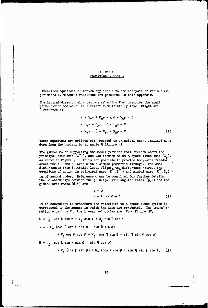
Linearized equations of motion applicable to the analysis of various ex- perimentally measurel responses are presented in this appendix.
The lateral/directional equations of motion that describe the small perturbation motion of an aircraft from initially level flight are (Reference 7)
v - Yvv + U0r - g 0 - W^ = 0
-Ivv-Lrr+|)-Lpp = 0
- Nvv + f - Nrr - Npp = 0 (1)
These equations are written with respect to principal axes, inclined nose down fron the horizon by an angle f) (Figure k).
The gimibal mount supporting the model provides roll freedom about the principal body axis (X ), and yaw freedom about a space-fixed axis (Zf),
as shown in Figure 31. It is not possible to provide body-axis freedom about the X and Z axes with a simple geometric linkage. For small disturbances from initially level flight, the difference between the equations of motion in principal axes (X , Z ) and gimbal axes (X , Z»)
is of second order. Reference 6 may be consulted for further details. The relationships between the principal axis angulai* rates (p,r) and the gimbal axis rates (^,f) are
P = 0
r = H cos 0 w f (2)
It is convenient to transform the velocities to a space-fixed system to correspond to the manner in which the data are presented. The transfor- mation equations for the linear velocities are, from Figure 32,
U = Uf cos Tl cos f + Vf sin Y + Wf sin Tj coe Y
V = - U. (cos T| sin f cos 0 + sin T\ sin 0)
+ V_ cos Y cos 0 + W_ (cos 11 sin 0 - sin T| sin Y cos 0)
w = U- (cos T\ sin Y sin 0 - sin T) cos 0)
- V (cos Y sin 0) + W (cos T) cos 0 + sin Tl sin Y sin $', (3)
59
■MMMHHMMMMMSHMMIMMaa
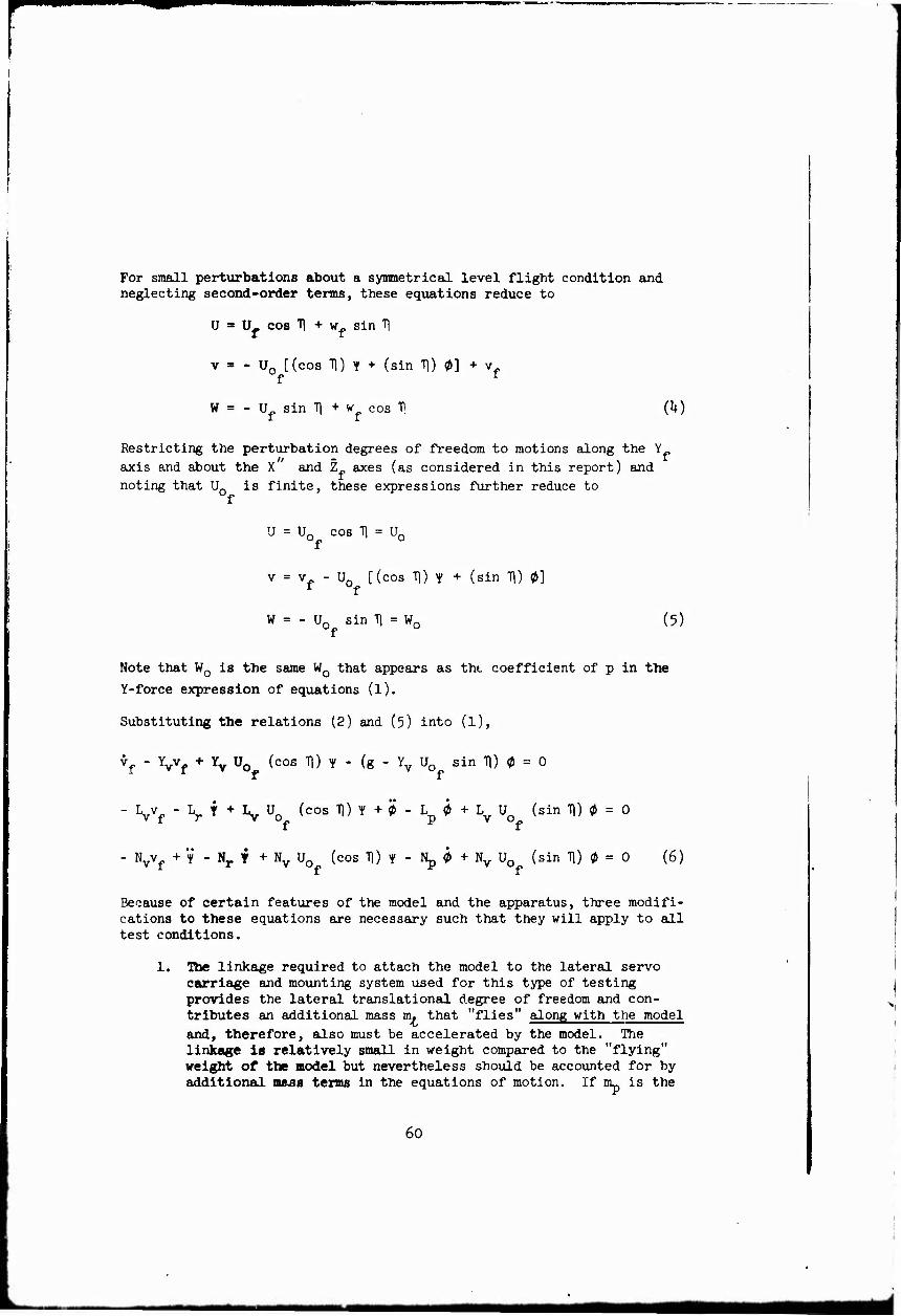
For small perturbations about a symmetrical level flight condition and neglecting second-order terms, these equations reduce to
U = U_ cos Tl + w» sin 11
v = - U0 [(cos Tl) f + (sin 11) 0] + v. f t
W = - U sin T] + w cos tl (U)
Restricting the perturbation degrees of freedom to motions along the Y„
axis and about the X and Z axes (as considered in this report) and
noting that U0 is finite, these expressions further reduce to
U = Un cos 11 = Ur
v = v. - Un [(cos Tl) Y + (sin T]) 0]
W = - U0 sin T) = W0 (5)
Note that W0 is the same W0 that appears as the coefficient of p in the
Y-force expression of equations (l).
Substituting the relations (2) and (5) into (l),
vf - Yvvf + Yv U0 (cos Tl) i - (g - Yv U0 sin Tl) 0 = 0
- Lvvf " Lr t + Iv U0 (cos Tl) Y + 0 - Lp 0 + Lv Uo (sin H) 0 = 0
- Nvvf + V - Nj. f + Nv U0 (cos Tl) Y - Np 0 + Nv U0 (sin T]) 0 = 0 (6)
Because of certain features of the model and the apparatus, three modifi- cations to these equations are necessary such that they will apply to all test conditions.
1. The linkage required to attach the model to the lateral servo carriage and mounting system used for this type of testing provides the lateral translational degree of freedom and con- tributes an additional mass m. that "flies" along with the model and, therefore, also must be accelerated by the model. The linkage is relatively small in weight compared to the "flying" weight of the model but nevertheless should be accounted for by additional mass terms in the equations of motion. If nip is the
60

1
total mass of the model resting on the pivot axis, then the total accelerated mass in the lateral direction HL is equal to nu + n. •
This mass is larger than the trim vertical aerodynamic force on the model divided by the acceleration due to gravity. For analysis purposes the "flying" mass is considered to be the vertical aerodynamic force divided by the acceleration due to gravity. This value was ^et by the conditions of the longitudinal tests of Reference 2. This dynamic model-mount characteristic requires the modification of all terms in the side force equation, except the- acceleration term, by a mass ratio defined as m/m. and equal to 0.970 in value.
2. In certain of the test conditions as indicated in Table III, the center of gravity of the model was not located at the pivot axis of the model. Equations (6) may be considered to be written about the pivot axis of the model, which represents the full- scale center-of-gravity position about which the derivatives are determined. Additional terms are necessary in the equations of motion to account for the displacement of the model center of gravity. These are
AL. = + Vcg Ix
L?£
AN. ^cg »p
Vcg h
W z
eg X
where m and W are the pivoting mass and pivoting weight of the model respectively.
3. Mechanical springs were added about the model roll axis and the model yaw axis to produce oscillatory motions in some single- degree-of-freedom tests. The following terms should be added for these tests:
Ah = i»
AN = - _S? (8^ m Iz
The values of the spring constants are given in Table III.
61

With these modifications, the equations of motion that apply to the ex- periments axe
^f " 5- Yvvf + i| Yv uof (cos "H) ^ - ^ (g - Yv U0f sin Tl) 0 = 0
^2 vf - Lvvf - Lr t + Lv Uo (cos H) Y + 0 - Lp 0
m W„ z. + L U sin Tl + -£—SS 0 = 0
I v 0f. x 1
X .... IB ., . / S . ■Z&-2 vf - Nvvf + Y - Nr Y + I Nv U0f cos Tl + ^ | y
N 0 + Nv U0 (sin Tl) 0 = 0 (9) f
For the restricted degree-of-freedom tests, the following reduced sets of equations apply.
1. In two degrees of freedom, with fy = k^ = 0 m m
a. vf, 0 (Y = 0)
^f - ir Vf - ^ (e " Yv uo sin T1) ^ = 0 i nu v t a* v O-
. fSSJÜE vf - Ivvf + 0 - L 0 + [Ly U0 sin Tl + -E-!£ß) 0 = 0 -"^x ' \ f Ix /
7 do)
b. 0, Y (vf = 0)
- L Y + L U (cos TO Y + 0 - L 0 f / w \
+ [LV U0 sinTl + -2^g'0 = 0
V - »„ ♦ + llv Urt (coa Tl) Y - 1L 0 + Nv U0 (sin Tl) 0 = 0 "r "v wo p " "v -o.
(11)
62
tmmmmm warn

2. In the single-degree-of-freedom experiments with mechanical springs, the equations of motion are
a. 0 (T = 0, v. = 0)
W« z. 0-^0+—+^^ sin Tl + -2--£ß 1 0 = 0 (12)
b. Y (0 = 0, v, = 0)
V - N * + ( N U cos Tl + —2) Y = 0 V o (13)
3. In the single-degree-of-freedom tests without mechanical springs, the equation of motion is
a. Y (0 = 0, vf = 0, ky = 0) m
t - Nr Y + Nv U0 (cos 11) Y = 0 (1^)
63
MMMMHilHaatiaMuMMI

MODEL 6IMBAL YAW AXIS
MODEL GIMBAL ROLL AXIS
U^lVcosi; -i-Wf sin 17 W'-Uo-sin 17-»-Wi cos 17
FOR </)-^-vf DEGREES OF MODEL FREEDOM THE INSTANTANEOUS RESULTANT VELOCITY IS Ö0f+7f - Ö+? ♦!
Not«»- X.- Y. - Z. or« tpoc« fixed ax«t, X.- Y plan« Is horizontal.
X^-Yf —Zf or« ipoc« flx«d ox««, initially alignad with principal axis of v«hicl«. X"—Y^—Z" or« principal ax«s of v«hicl«. U,v and W ar« for small ptrturbotions about l«v«l symmotrical flight.
Figure 31« Model Axes Systems and Variables for Forward Flight Lateral/Directional Tests.
6!+
mm mm
>
o
-§ ro
O
X •H
I g OJ • Ü 4->
IO a) C ft a» w S
0> a M ^ s ft, ^
w 5 ■H
•H O O
0)
2:
«4-. Of o C O O Vi
-p a)
B <u
o >> •iH CO m
0)
•H
65

Unclassified Jjcurtt» cu»»tac»tio«
DOCUMENT CONTROL DATA -R&D (tturtlr cl—lltcmllmt »I in/«, W^» »I ttmmmct ant Inötmtnt miMUllt* muH W MMratf mltmi UM «MM» I JlllwtJ
I. OWigiNATIM« *CTIVITY fCl^lMl» «MOarJ
Department of Aerospace and Mechanical Sciences Princeton University
, NKPOKT •■CUMITV CLAttlFIClkTION
Unclassified
1. KKPORT TITL«
AN INVESTIGATION OF THE DYNAMIC STABILITY CHARACTERISTICS OF A QUAD CONFIGURATION, DUCTED-PROPELLER V/STOL MODEL VOIW* Ill - PHASE III - LATERAL/DIRECTIONAL DYNAMICS AT HIGH DUCT INCIDENCES
i. o«.em.»Tivi NOTis (Trpt ml Final Data Report
if" —* tochMlT« ärnft)
(. AUTMOnitl fWBStSSZ mUm» Mttol. lamlmamm)
William F. Putman John P. Kukon Joseph J. Traybar Howard C. Curtiss, Jr.
November 1968 im. TOTAL NO. OP PACK!
-U. T*. NO. or ««F»
■a. CONTMACT OR «NANT NO.
DAAJO2-67-C-0O25 k. PMOJCCT NO.
lFl6220it Al 1+233
M. OWIOINATOIft HCPOKT NUkraCHItl
USAAVLABS Technical Report 68-U9C
. OTMKIt RiroRT NOIII (Amr •*•' wliw »ml mmf W —Igmm*
Aerospace Sciences Report 81+7 10. OKTRIBUTION ITATCMCNT
This docuaent has been approved for public release and sale; its distribution is unliaited.
Voluae III of a 4-voluae report.
It. AatTKACT
II. •PONtOKIN« MILITARY ACTIVITY
U.S. Army Aviation Materiel Laboratories Fort Eustis, Virginia
\ The results of experiments to determine the lateral/directional dynamic stability characteristics of a quad configuration, ducted-propeller v/STOL aircraft at four low-speed/high-duct-incidence triii conditions (i, = 80° , 70°, 60°, and 50°,) are
presented. Lateral/directional transient responses in various degrees of freedom were measured using a dynamic model on the Princeton Dynamic Model Track. The data presented Include time histories of the model motions in various lateral/directional degrees of freedom that occur when the model is disturbed from trinmed flight.
The dynamic model employed in these experiments is a generalized research model arranged to represent closely the Bell X-22A V/STOL aircraft.
The data presented in this report comprise the third phase of a three-phase investi- gation of the dynamic stability characteristics of a quad configuration, ducted- propeller V/STOL aircraft at low speeds and high duct incidences. The other two phases pertain to the lateral and longitudinal hovering stability characteristics, presented in Reference 1, and the longitudinal characteristics at four low-speed/ high-duct-incidence trim conditions presented in Reference 2.
• «»•. I JAN M. ■MICM It Unclassified
■•cnrltjr dattlfleatfoa
md
Unclassified Sacnrity Claaslflcation
KIT mono»
V/STOL Dynamics Stability Longitudinal Stability Transient Response Bell X-22A Hovering Characteristics Lateral Stability
Unclassified
11947-68