3He Top Loading Cryostat - NIST Center for Neutron Research
15
3 He Top Loading Cryostat User Manual Table of Contents: I. Introduction: .................................................................................... 2 II. Valve Names: .................................................................................. 3 III. Sample Loading:.............................................................................. 3 IV. Liquid Nitrogen Cooldown: ............................................................ 4 V. Liquid Helium Cooldown................................................................ 5 VI. Cooling to Base Temperature:......................................................... 6 VII. Sample Change: ............................................................................... 8 VIII. Temperature Contol ......................................................................... 9 IX. System Warm-up ........................................................................... 10 X. Drawings & Pictures ..................................................................... 11
Transcript of 3He Top Loading Cryostat - NIST Center for Neutron Research
3He Top Loading Cryostat User Manual
Table of Contents:
I. Introduction: .................................................................................... 2 II. Valve Names: .................................................................................. 3 III. Sample Loading:.............................................................................. 3 IV. Liquid Nitrogen Cooldown: ............................................................ 4 V. Liquid Helium Cooldown................................................................ 5 VI. Cooling to Base Temperature:......................................................... 6 VII. Sample Change:............................................................................... 8 VIII. Temperature Contol......................................................................... 9 IX. System Warm-up........................................................................... 10 X. Drawings & Pictures ..................................................................... 11
I. Introduction:
1. This is a complicated system that should only be run by an experienced user or
member of the sample environment team. This manual is not meant to be a
substitute for that, but instead should be a point of reference and a learning tool.
For more information contact: Evan Fitzgerald (301-975-6657) or Dan Dender
(301-975-6225).
2. What makes this system unique is that it is a top loading 3He system. Along
with this feature come some inherent problems that had to be overcome to get
the system to work. To reach a base temperature of 300mK the sample stick
must make solid contact with the 3He pot and, for thermal shielding it, must also
make contact with the 1K pot and the 4He reservoir. To accomplish this a force-
generator was designed which pushes down on the sample stick and mates
matching surfaces on the stick and the inside of the sample tube. The mating
points are then connected by copper braids to the respective parts of the system.
The system, however, still needs more cooling power to over come the large
thermal mass of the stick and assembly, so there are actually two identical,
independent 3He systems (insert A and B).
2
II. Valve Names:
1. V-1A/B = Charcoal cooling control 2. V-2A/B = 1K pot needle valve 3. V-3 = Vacuum space safety pressure relief 4. V-4A/B = 3He dump fill 5. V-5A/B = 1K pots pumping and over pressure 6. V-6A/B = Charcoal cooling flow gauge 7. V-7 = Air lock double o-ring evacuation 8. V-8 = Air lock evacuation 9. V-9 = Sample well gate valve 10. V-10 = Inner vacuum chamber (IVC) evacuation 11. V-11 = IVC safety pressure relief 12. V-12 = Vacuum jacket evacuation 13. V-13 = Helium reservoir exhaust/pressure relief Note: See “Figure 2” for a labeled picture of the top of the cryostat, “Figure 3” for a labeled picture of the sorb cooling valves and helium reservoir exhaust/pressure relief valve and “Figure 5” for a labeled picture of the sample stick.
III. Sample Loading:
1. With the system at room temperature, mount the sample stick on top of the
cryostat and bolt it into place. If the IVC is known to be under vacuum connect
a turbo pump to V-8 and evacuate the air lock. If the IVC is at atmospheric
pressure leave the airlock alone and continue. It is a good idea to occasionally
clean and grease the sample stick, but the amount of grease should be very
small.
2. Open V9 and slide the stick slowly into the sample well until it is stopped by
the 0.5K thermal anchor stage. Screw the force generator down until it offers
resistance to compress the stick slightly. Do NOT tighten the force generator all
the way. See “Figure 5” for a picture of the sample stick mounted on the
cryostat.
3
3. After checking that the hose between V7 and V8 is properly connected close
both valves and evacuate the IVC through V10 with a turbo pump. When the
vacuum is less than 5 x10⁻⁴ Torr disconnect the turbo pump and connect a leak
detector to V10.
4. Leak check the stick’s hoses, valves, seals and connectors. Using a rough
pump evacuate the 1K pot through V-5A/B, leaving V-2A/B closed, then
backfill with He gas while monitoring the leak detector. Leave the 1K pot filled
with He gas and the IVC evacuated. Disconnect the leak detector.
IV. Liquid Nitrogen Cooldown:
1. Add a small amount of 4He gas into the IVC through V-10 by attaching a
rubber hose, pinching it off about 1 foot down and then briefly opening then
closing the valve.
2. Using a rough pump evacuate the helium reservoir through V-13, backfill with
He gas and repeat three times, the last time leaving it filled with He gas. Start
filling the helium and nitrogen reservoirs with LN2.
3. Attach the rough pump to V-5A/B and pump on the 1K pots. Throughout the
fill occasionally open V-2A/B one turn and then close it. This will prevent the
needle valve from getting stuck. Stop this procedure when the 1K pot reaches
less than 100K or when you stop filling the He reservoir with LN2.
4. Close V-2A/B and pump out the 1K pots then back fill with He gas and seal
off.
5. Let the LN2 in the nitrogen reservoir fill all the way to the top, but stop filling
the helium reservoir after approximately one hour or when the LN2 level meter
4
reads above 70%. This assumes the two are filling at around the same rate with
the goal being to leave a few inches of LN2 in the helium reservoir.
6. Gently tighten the force generator if necessary as the stick will shrink as it
cools, but do not over-tighten.
7. Let the system sit overnight to completely cool to Nitrogen temperature.
V. Liquid Helium Cooldown
1. If by the next morning the sensors read greater than 100K add more nitrogen to
the helium reservoir and let things cool completely.
2. If the sensors are all reading near LN2 temperature blow the LN2 out of the
helium reservoir by inserting a tube into the fill port and applying 3-5psi with
helium gas into V-13. The fill port can slide up and down, so it needs to be
pushed all the way down and then screwed into place. The nitrogen will flow
out the tube, so use a rubber hose to direct it into a cryogenic liquid container.
3. When all of the LN2 is out use a rough pump to evacuate the helium reservoir
through V-13 with V-2A/B open, backfill with He gas and repeat three times.
Leave the reservoir filled with He gas the last time and then close V-2A/B.
4. Start transferring liquid helium (LHe) through the fill port after unscrewing it
and slightly raising it. Remember to keep the pressure low (<3psi) and to
remove V-13 to allow the exhaust to exit. See “Figure 3” for a picture of the
helium exhaust valve.
5. The LHe is full when the level meter reads >100% and a large dense plume of
vapor exhausts through V-13. Remove the transfer line then seal the reservoir.
V-13 should be sealed with the over-pressure valve to maintain a pressure of
5
about 3psi in the helium reservoir. See “Figure 3” for a picture of the helium
exhaust valve.
6. Monitor the temperatures of both 3He inserts to make sure they cool steadily.
When their temperatures reach approximately 25K start evacuating the IVC
through V-10 using a turbo pump and allow at least 3 hours of pumping time.
Do not allow the system to pump out longer than 8 hours as the sample
temperature will slowly rise and be unacceptably high.
7. Without the exchange gas in the IVC cooling of the sample stick is dependant
on the contact to the multiple mating surfaces. The force generator should be
screwed tight, but not excessively so, to maintain contact with the cryostat.
VI. Cooling to Base Temperature:
1. If the helium was recently filled wait a few minutes for some pressure to build
up in the reservoir. Open V-1 and V-6 and verify flow by seeing the small black
indicator ball jump up to a flow rate. If the ball doesn’t move, even with a light
tap, close V-1 immediately. The absence of flow is a problem that should be
promptly reported to the sample environment team. If flow is verified close
both V-1 and V-6 and continue on. See “Figure 3” for a picture of the valves
involved in this procedure.
2. If you are certain all of the He exchange gas is out of the IVC begin pumping
on the 1K pot. Connect a high volume rough pump to V-5A/B and pump out the
lines back to V-2A/B. Slowly open V-2A/B and adjust to reach the lowest
sustainable base temperature as measured on the 1K pot sensors (~1.1 – 1.3 K).
See “Figure 4” for a picture and description of the electronics rack setup.
6
3. When the 1K pots are steadily at their base temperatures set the temperature of
the 3He sorbs directly to 20K (see below to turn the ramp feature off) and turn
their heater on to “Medium”. See “Figure 4” for a picture and description of the
electronics rack setup. The 1K pot temperatures will briefly rise while they cool
the “warm” 3He gas. After the sorb has reached 20K turn on the ramp feature by
pressing the “control setup“ button on the sorb controller and using the “enter”
button to scroll to the ramp option. Set the ramp on and then set the rate to 1
K/m. With the ramp enabled change the setpoint to 40K and the controller
should slowly ramp there. The sample temperature should slowly decrease to
around 1.8K. The 3He is condensing when the 3He pots reach 1.8K. Continue
to condense for at least half an hour after this point (1 hour condensation =
~25hours at base; 4 hours of condensation = ~39hours at base).
4. Once the 3He has condensed for the desired amount of time turn off the
charcoal adsorption pump heater and slowly open V-1 and V-6. Once again
watch to see the black ball on the flow meter measure a flow rate and close the
valve if it doesn’t move. The recommended flow rate is approximately 1,000cc
per minute and the charcoal adsorption pump should slowly cool to, and remain
below, 5K.
5. The 3He pot temperatures will slowly drop to 300mK followed closely by the
sample temperature. The 1K pots are the main contributors to helium
consumption when running and should be monitored and adjusted as necessary
to lower their temperature and minimize this consumption. The Silicon Diode
type sample sensor (A), which bottoms out at 1.4K should be disabled to remove
7
the heat load it contributes. Press the “Input Setup” button on the sample
sensor’s controller and change the first setting, “Enable”, from “on “ to “off”.
See “Figure 4” for a picture and description of the electronics rack setup.
VII. Sample Change:
1. Connect a turbo pump to V-8, leaving it closed, and evacuate the air lock
assembly. See “Figure 5” for a picture of the airlock and associated valves.
Open V-7 and begin to slowly raise the sample stick. As the stick is pulled up it
will frost up and can freeze the o-ring seal on the air lock. To avoid this pause
every few minutes and allow the stick to warm or heat it with a heat gun. The
clamp can be used to hold the stick in place as you are warming it up.
2. When the stick is all the way up and will not go any farther clamp it into place,
close V-9 and V-7 and stop the pump. The air lock and stick can be brought to
atmospheric pressure by slowly opening V-8. Helium gas can alternatively be
added to the air lock to slowly warm the sample if necessary. (Note: Helium gas
will expand as it warms and will quickly build up pressure in a trapped volume
like this. Contact a member of the sample environment team before attempting
this procedure.)
3. Unbolt the stick from the top of the cryostat, remove it and cover V-9 with the
blank flange to protect it.
4. To load another sample re-mount the stick and bolt it down. Evacuate the air
lock with V-7 and V-8 open.
5. Have an experienced user add a small amount of 3He gas to the IVC through V-
10, close V-8, open V-9 and begin slowly lowering the stick. The use of 3He
8
instead of 4He will decrease the amount of time required to pump out the IVC
and should only be used when time is a major factor. Continue pumping on V-7
to prevent any air from getting by the double o-ring seal. The LHe will begin to
rapidly boil off due to the large heat load. To decrease the helium boil off lock
the stick in place and let it sit for fifteen minutes every few feet. The stick
should be as cold as possible, but certainly less then 100K, before making
contact with the mating surfaces in the sample well.
6. When the stick sensors reach approximately 25K pump out the IVC through V-
10 using a turbo pump for at least a few hours.
7. Continue following the directions from step 5 of section V.
VIII. Temperature Contol
1. T < 1K: When starting from base temperature the sorb can be gently warmed
(Tsorb < 15K, reduce flow through V6 ) to increase sample temperature slightly.
This method can actually increase the time you can stay below 1.8K. Using the
sample heater at its lowest power setting is another option, but this will
dramatically reduce the amount of time you can stay below 1.8K.
2. 1K < T > 1.8K: The 3He must be condensed and pumped on to work below
1.8K, but it is difficult to make it last for more than a few hours when working
above 1K. To work in this temperature range use both the sample heater and the
sorb heater. Warming the sorb to about 20 or 30K will slow the pumping of the
3He and then the sample heater can be used at a low power to control the
temperature of the sample.
9
3. 1.8K < T > 4.2K: In this range cooling from the 1K pots is necessary, but
pumping on liquid 3He is not. The sorb temperature should be set at 25K or
above to provide exchange gas in the 3He circuit. The sample heater can then be
used at an appropriate power.
4. 4.2K < T > 300K: At temperatures close to 4 K the same method as suggested
in #3 should be employed. At higher temperatures the cooling from the 1K pot
will become useless and they can be closed off to conserve LHe. At this point
the sorb temperature is also not important, so its heater can be turned off. The
sample will then be isolated and its temperature entirely dependant on the heater
and radiative cooling. Above 20K the RuOx sample sensor (B) will not read, so
the control sensor in the 340 controller and the sample temperature sensor read
by ICP must be changed to the Silicon Diode sensor (A).
5. Note: For temperatures above approximately 30K it is necessary to add
exchange gas to cool the sample back down at a reasonable rate. This exchange
gas will then take a few hours to pump back out if you wish to continue below
4K.
IX. System Warm-up
1. Valves 2A/B and 5A/B should be closed to stop pumping on the 1K pots.
Although there is cold He trapped between valve 2 and 5 there is an
overpressure valve that will safely release any excess pressure.
2. Close valves 1A/B to seal the cooling circuit for the charcoal pumps and
prevent air from being sucked in when the LHe runs out.
10
3. Finally loosen the force generator slightly so that it will be easier to remove at
room temperature after the stick has expanded.
4. As long as the LHe reservoir is sealed as normal the system should be safe to
warm up on its own.
X. Drawings & Pictures
11
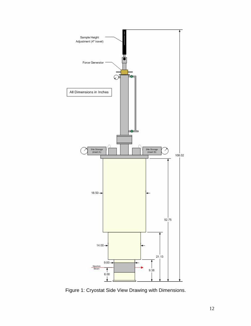
Figure 1: Cryostat Side View Drawing with Dimensions.
12
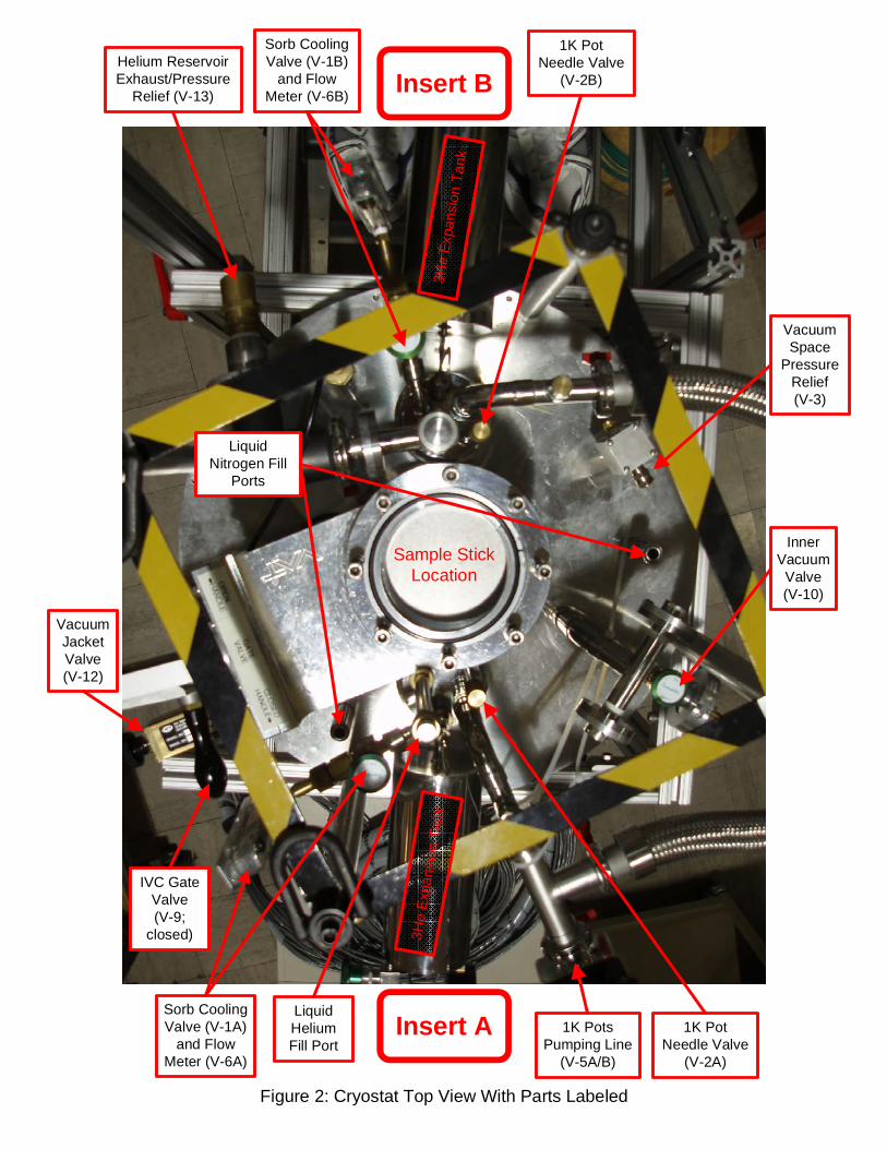
Insert B
Insert A
InnerVacuum
Valve(V-10)
1K PotNeedle Valve
(V-2B)
Sorb CoolingValve (V-1B)
and FlowMeter (V-6B)
Helium ReservoirExhaust/Pressure
Relief (V-13)
VacuumJacketValve(V-12)
LiquidNitrogen Fill
Ports
IVC GateValve(V-9;
closed)
Sorb CoolingValve (V-1A)
and FlowMeter (V-6A)
LiquidHeliumFill Port
1K PotsPumping Line
(V-5A/B)
1K PotNeedle Valve
(V-2A)
Sample StickLocation
3He
Exp
ansi
on T
ank
3He
Expa
nsio
n Ta
nk
Figure 2: Cryostat Top View With Parts Labeled
VacuumSpace
PressureRelief(V-3)
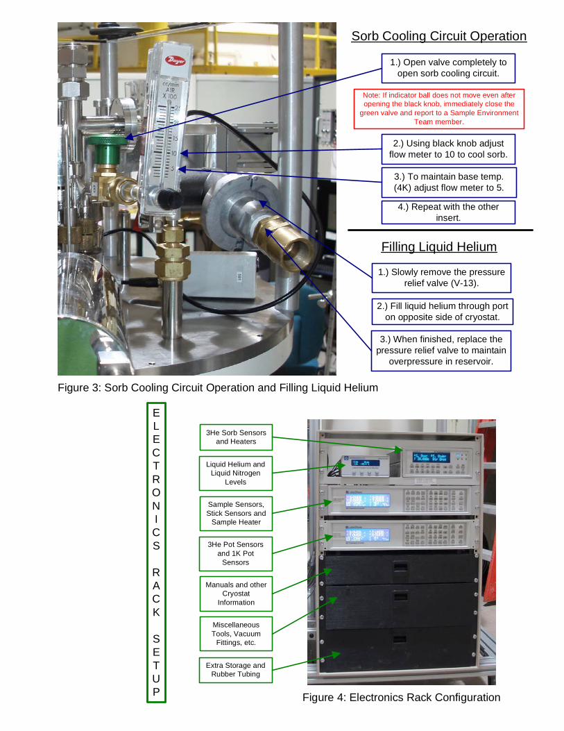
Figure 3: Sorb Cooling Circuit Operation and Filling Liquid Helium
Figure 4: Electronics Rack Configuration
ELECTRONICS
RACK
SETUP
1.) Open valve completely toopen sorb cooling circuit.
2.) Using black knob adjustflow meter to 10 to cool sorb.
3.) To maintain base temp.(4K) adjust flow meter to 5.
Sorb Cooling Circuit Operation
Note: If indicator ball does not move even afteropening the black knob, immediately close the
green valve and report to a Sample EnvironmentTeam member.
4.) Repeat with the otherinsert.
Filling Liquid Helium
1.) Slowly remove the pressurerelief valve (V-13).
3.) When finished, replace thepressure relief valve to maintain
overpressure in reservoir.
2.) Fill liquid helium through porton opposite side of cryostat.
3He Sorb Sensorsand Heaters
Liquid Helium andLiquid Nitrogen
Levels
Sample Sensors,Stick Sensors and
Sample Heater
3He Pot Sensorsand 1K Pot
Sensors
Manuals and otherCryostat
Information
MiscellaneousTools, Vacuum
Fittings, etc.
Extra Storage andRubber Tubing
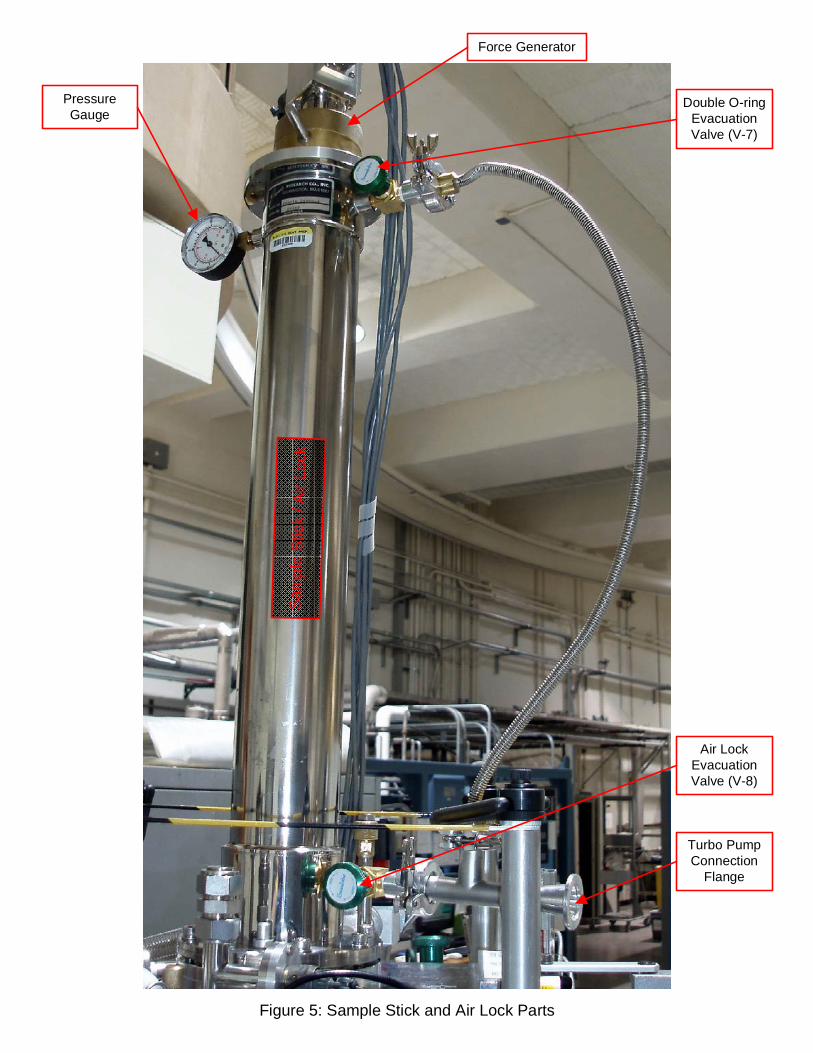
Figure 5: Sample Stick and Air Lock Parts
PressureGauge
Force Generator
Double O-ringEvacuationValve (V-7)
Air LockEvacuationValve (V-8)
Turbo PumpConnection
Flange
Sam
ple
Stic
k / A
i r Lo
ck